EP2955073A1 - Device for the towing vehicle-trailer connection - Google Patents
Device for the towing vehicle-trailer connection Download PDFInfo
- Publication number
- EP2955073A1 EP2955073A1 EP15169967.5A EP15169967A EP2955073A1 EP 2955073 A1 EP2955073 A1 EP 2955073A1 EP 15169967 A EP15169967 A EP 15169967A EP 2955073 A1 EP2955073 A1 EP 2955073A1
- Authority
- EP
- European Patent Office
- Prior art keywords
- configuration
- tubular element
- closing
- male
- coupling
- Prior art date
- Legal status (The legal status is an assumption and is not a legal conclusion. Google has not performed a legal analysis and makes no representation as to the accuracy of the status listed.)
- Granted
Links
Images



Classifications
-
- B—PERFORMING OPERATIONS; TRANSPORTING
- B60—VEHICLES IN GENERAL
- B60T—VEHICLE BRAKE CONTROL SYSTEMS OR PARTS THEREOF; BRAKE CONTROL SYSTEMS OR PARTS THEREOF, IN GENERAL; ARRANGEMENT OF BRAKING ELEMENTS ON VEHICLES IN GENERAL; PORTABLE DEVICES FOR PREVENTING UNWANTED MOVEMENT OF VEHICLES; VEHICLE MODIFICATIONS TO FACILITATE COOLING OF BRAKES
- B60T17/00—Component parts, details, or accessories of power brake systems not covered by groups B60T8/00, B60T13/00 or B60T15/00, or presenting other characteristic features
- B60T17/04—Arrangements of piping, valves in the piping, e.g. cut-off valves, couplings or air hoses
- B60T17/043—Brake line couplings, air hoses and stopcocks
-
- B—PERFORMING OPERATIONS; TRANSPORTING
- B60—VEHICLES IN GENERAL
- B60D—VEHICLE CONNECTIONS
- B60D1/00—Traction couplings; Hitches; Draw-gear; Towing devices
- B60D1/58—Auxiliary devices
- B60D1/62—Auxiliary devices involving supply lines, electric circuits or the like
- B60D1/64—Couplings or joints therefor
-
- B—PERFORMING OPERATIONS; TRANSPORTING
- B60—VEHICLES IN GENERAL
- B60T—VEHICLE BRAKE CONTROL SYSTEMS OR PARTS THEREOF; BRAKE CONTROL SYSTEMS OR PARTS THEREOF, IN GENERAL; ARRANGEMENT OF BRAKING ELEMENTS ON VEHICLES IN GENERAL; PORTABLE DEVICES FOR PREVENTING UNWANTED MOVEMENT OF VEHICLES; VEHICLE MODIFICATIONS TO FACILITATE COOLING OF BRAKES
- B60T11/00—Transmitting braking action from initiating means to ultimate brake actuator without power assistance or drive or where such assistance or drive is irrelevant
- B60T11/10—Transmitting braking action from initiating means to ultimate brake actuator without power assistance or drive or where such assistance or drive is irrelevant transmitting by fluid means, e.g. hydraulic
- B60T11/108—Transmitting braking action from initiating means to ultimate brake actuator without power assistance or drive or where such assistance or drive is irrelevant transmitting by fluid means, e.g. hydraulic to a trailer fluid system
Definitions
- the present invention relates to device for the towing vehicle-trailer connection.
- to date towing vehicles are connected to the relative trailer through a connection device comprising a male coupling associated with the towing vehicle and a relative female coupling associated with the trailer.
- connection device allows putting in communication the braking system of the towing vehicle with that of the trailer, so that the braking of the towing vehicle operated by the operator also causes the braking of the towed trailer.
- the braking system of the trailer is then driven by the braking system of the prime mover in order to synchronize the braking forces acting on same.
- connection device between the towing vehicle and its trailer to have a pair of male couplings able to be inserted inside a pair of relative female couplings, of which one is connected to the braking system of the trailer and the other to the parking and/or automatic brake of the trailer itself, in such a way that, if the aforementioned male couplings detach from the relative female couplings, and the oil supply is therefore interrupted to the braking system of the trailer, the relative parking and/or automatic brake starts operating.
- the female coupling connected to the parking and/or automatic brake of the trailer is able to send oil under pressure to a control device able to maintain deactivated the parking and/or automatic brake itself.
- the main aim of the present invention is to provide a device for the towing vehicle-trailer connection which allows ensuring automatic activation of the parking and/or automatic brake of the trailer in the event of the male couplings coming out of the relative female couplings even without the driver of the towing vehicle having previously engaged the relative parking and/or automatic brake.
- one object of the present invention is to ensure that, in a simple and safe constructive manner, as a result of the coming out of the male couplings from their female couplings, the working fluid sent to the control device of the parking brake of the trailer is unloaded so as to allow the automatic actuation of the parking and/or automatic brake itself.
- Another object of the present invention is to provide a device for the towing vehicle-trailer connection which allows to overcome the mentioned drawbacks of the prior art within the ambit of a simple, rational, easy, effective use and low cost solution.
- the device 1 comprises a base body 2 associable with a trailer (not shown in the illustrations) and wherein is defined at least a first female coupling 3, communicating with a control line 4 connectable to the braking system 5 of the trailer, and at least a second female coupling 6, communicating with at least an additional line 7 connectable to the parking and/or automatic brake 8 of the trailer itself and with at least a by-pass line 9 connectable to an unloading tank 10.
- control line 4 is able to supply the braking system 5 of the trailer with a working fluid at a pressure generally between 0 and 150 bar, while the additional line 7 is able to supply a command device 11 of the parking and/or automatic brake 8 at a pressure generally between 15 and 35 bar in such a way as to maintain the parking brake itself open, or deactivated.
- the device 1 then comprises also a first and a second male couplings, identified with reference numbers 12 and 13 respectively, which are associable with the braking system 14 of the towing vehicle, and in particular are connectable to valves which are able to send, respectively, a first and a second control signal to the trailer.
- these control signals are pressure signals, i.e., they correspond to the sending of the working fluid towards the first and second male couplings 12 and 13 at a first and at a second pressure, respectively.
- the first male coupling 12 is able to transmit a first pressure signal for operating the brakes of the trailer while the second male coupling 13 is able to send to the trailer a second substantially constant-pressure signal contained within a predefined range.
- the body 2 also comprises at least a third female coupling 70 intended to receive at least a third male coupling 71 connectable, e.g., to an unloading tank not shown in the illustrations.
- the tank 10 is of the dynamic type, e.g. of the membrane or spring type, or is able to apply a low backpressure on the working fluid incoming from the by-pass line 9 and is communicating with the control line 4.
- the device 1 comprises valve means 17 able to selectively put in communication and isolate between them the additional line 7 and the by-pass line 9 respectively, as a result of the exit and insertion of the second male coupling 13 within the second female couplings 6.
- the command device 11 has two work positions, of which a deactivation position and an activation position of the parking and/or automatic brake and elastic means counteracting the displacement thereof from the activation to the deactivation position.
- the additional line 7 is therefore able to send fluid under pressure to the command device 11 when the second male coupling 13 is inserted within the second female coupling 6 so as to compress the elastic means of the command device itself and maintain it in the deactivation position. Following the coming out of the second male coupling 13 from the second female coupling 6 the fluid under pressure present in the additional line 7 is unloaded through the by-pass line 9 so that the command device 11 is pushed by its elastic means in the activation position.
- the valve means 17 comprise at least a first tubular element 26 inserted in a sliding manner within the second female coupling 6 to open/close the connection gap 27 between the additional line 7 and the by-pass line 9.
- the first tubular element 26 is movable between a release configuration, which corresponds to the position taken by the same following the coming out of the second male coupling 13 from the second female joint 6 and wherein the additional line 7 is placed in communication with the by-pass line 9, and a fastening configuration, wherein the additional line and the by-pass line 9 are mutually isolated.
- the first tubular element 26 has a plurality of intermediate configurations, which occur following the insertion of the second male coupling 13 within the second female coupling 6 up to the locking of the same, and in which the first tubular element itself interrupts the connection between the additional line 7 and the by-pass line 9.
- the working fluid present in the additional line 7 is sent to the command device 11 to maintain it in the deactivation position, while in the release configuration the working fluid present in the additional line 7 is unloaded through the by-pass line 9 so that the pressure acting on the elastic means of the command device 11 decreases progressively and the latter is pushed by the elastic means themselves in the activation position.
- the second male coupling 13 defines a first channel 31 of the working fluid and has a first closing element 32 of the first channel itself movable between a relative opening configuration and a relative closing configuration.
- elastic means 51 are provided able to counteract the displacement of the first closing element 32 to the opening configuration.
- the valve means 17 also comprise a second tubular element 28 inserted in a sliding manner within the first tubular element 26 and defining a second channel 29 for the transit of the working fluid, there being provided a second closing element 30 of the second channel itself.
- the second tubular element 28 is movable with respect to the second closing element 30 between a closing configuration and an opening configuration of the second channel 29.
- the first closing element 32 is able to contact the second closing element 30 by displacing from the closing configuration to the opening configuration, and the end of the second male coupling itself is able to contact the first tubular element 26 to displace it to the fastening configuration.
- the first tubular element 26 is able to drag in its displacement the second tubular element 28 to displace it to the relative opening configuration in order to place in communication the first with the second channels 31 and 29 for the transit of the working fluid.
- the second male coupling 13 comprises first sealing means 52 able to cooperate with the first closing element 32 when the latter is in the closing configuration and able to cooperate with the second tubular element 28 as a result of the insertion of the second male coupling 13 within the second female coupling 6.
- the first sealing means 52 are arranged at the inner wall of the second male coupling 13 delimiting the first channel 31.
- the second closing element 30 then comprises second sealing means 53 able to cooperate with the first tubular element 26 in its closing configuration.
- the end portion of the second closing element 30 facing the second male coupling 13 has a conformation diverging outwards, e.g. of the frustoconical shape.
- the first and second tubular elements 26 and 28 have, respectively, an abutment surface 26a and a counter-abutment surface 28a arranged facing one another.
- the abutment surface 26a is spaced from the counter-abutment surface 28a in the release configuration of the first tubular element 26, while it is able to contact it as a result of the displacement of the first tubular element itself to the fastening configuration.
- first elastic means 54 able to counteract the displacement of the first tubular element itself to the fastening configuration.
- Second elastic means 55 are also placed between the second tubular element 28 and the body 2 and able to counteract the displacement of the second tubular element itself to the opening configuration.
- the device 1 comprises at least a sealing element 56 associated with the body 2 and arranged downstream, with respect to the direction of insertion of the second male coupling 13 within the second female coupling 6, of the connection gap 27 between the additional line 7 and the by-pass line 9.
- This sealing element 56 is able to be contacted by the first tubular element 26 following the insertion of the second male coupling 13 within the second female coupling 6.
- the first tubular element 26 is able to contact the sealing element 56 before dragging in its displacement the second tubular element 28. More particularly, the first tubular element 26 is able to contact the sealing element 56 before the abutment surface 26a contacts the counter-abutment surface 28a to drag the second tubular element 28 in translation.
- the second channel 29 is therefore able to open after the first tubular element 26 achieves the fastening configuration.
- the sealing element 56 is arranged resting against the body 2 and defines a first groove 56a facing the additional line 7 and at least a second groove 56b facing the body 2, where such second groove 56b is communicating with the by-pass line 9 as a result of the contact of the sealing element 56 with the first tubular element 26. It follows, therefore, that the first groove 56a is subject to a pressure greater than that acting on the second groove 56b, therefore the sealing element 56 is pushed towards the walls of the body 2 so as to remain in place even after the return of the first tubular element 26 to the release configuration.
- the first male coupling 12 has a first duct 57 for the transit of the working fluid and a third closing element 58 of the first duct itself, which is movable between an opening and a closing configuration.
- elastic means 59 are provided able to counteract the displacement of the third closing element 58 to the opening configuration.
- the third closing element 58 is arranged at the axial extremity of the first duct 57 facing the first female coupling 3.
- the third closing element 58 also comprises third sealing means 60 able to cooperate with the inner wall of the first male coupling 12 delimiting the first duct 57 in the closing configuration.
- a further tubular element 61 defining a second duct 62 for the transit of the working fluid and a fourth closing element 63 of the second duct itself, which is movable between a relative closing configuration and a relative opening configuration.
- elastic means 64 are provided able to counteract the displacement of the fourth closing element 63 to its opening configuration.
- the further tubular element 61 has a plurality of openings 65 arranged at its side surface and the fourth closing element 63 is fitted externally to the further tubular element 61 so as to obstruct the openings 65 in its closing configuration.
- the third closing element 58 contacts the extremity of the further tubular element 61, moving towards its closing configuration, and the end of the first male coupling 12 is able to contact the fourth closing element 63 to move it to its opening configuration, so as to make the openings 65 accessible and place in communication the first duct 57 with the second duct 62.
- the device 1 also comprises a connection element 18 which has at least a first ring nut 18a fitted around the first female coupling 3 and at least a second ring nut 18b fitted around the second female coupling 6, where the first and the second ring nuts 18a and 18b are locked together, e.g. through a plate 18c.
- connection element 18 is movable with respect to the body 2 between an unlocking position, wherein it allows the displacement of the male couplings 12, 13 with respect to the corresponding female couplings 3, 6, and a locking position, wherein it prevents the relative displacement thereof.
- fastening and release means are also provided able to cooperate with one another to allow the locking and unlocking of the male couplings 12 and 13 with respect to the female couplings 3 and 6 as a result of the connection element 18 achieving the locking position and the unlocking position, respectively.
- the fastening and release means comprise at least two locking elements 21 each of which is associated with the body 2 at a relative female coupling 3, 6 and able to cooperate with the male couplings 12, 13 to prevent the displacement thereof with respect to the relative female coupling 3, 6; the connection element 18 being able to keep the locking elements 21 engaged with the relative male couplings 12, 13 in the locking position and to allow disengagement in the unlocking position.
- the fastening and release means comprise at least a first recess 22 defined on each ring nut 18a, 18b and at least a second recess 23 defined on each male coupling 12, 13.
- the locking elements 21 are positioned within a relative through hole 24 defined on the body 2, which contain them laterally, and are able to be inserted within the corresponding second recesses 23 as a result of the insertion of the male couplings 12, 13 within the relative female couplings 3, 6.
- connection element 18 in its locking position keeps pressed the locking elements 21 within the second recesses 23, while in its unlocking position the first recesses 22 are arranged at the locking elements themselves thus allowing the coming out of the male couplings 12, 13 from the relative female couplings 3, 6.
- connection element 18 in the locking position of the connection element 18 the locking elements 21 rest against a relative locator surface 25 defined by the connection element itself and which prevents its displacement from the relative second recess 23, while in the unlocking position of the connection element 18, the first recesses 22, by arranging themselves at the relative locking elements 21, allow the latter to come out of the relative second recesses 23.
- the locking elements 21 are of the ball type and the first and second recesses 22 and 23 are shaped like a circumference arc.
- elastic means 33, 34 are placed between the body 2 and the connection element 18 and able to counteract the displacement of the latter from the locking position to the unlocking position.
- the elastic means 33, 34 comprise first elastic means 33 interposed between the body 2 and the first ring nut 18a and second elastic means 34 interposed between the body 2 and the second ring nut 18b.
- guide means 35 are provided of the displacement of the connection element 18 between the locking position and the unlocking position.
- the guide means 35 comprise a guide element 35a locked together with the connection element 18, and in particular with the plate 18c, and inserted sliding inside a seat 35b obtained within the body 2.
- the seat 35b also defines an end-of-stroke surface against which the guide element 35a rests after the connection element 18 has reached the unlocking position.
- the guide element 35a is placed between the first and the second ring nuts 18a and 18b.
- the guide means 35 are therefore able to keep the plate 18c substantially orthogonal to the axes of the female couplings 3 and 6 during the displacement of the connection element 18 between the locking position and the unlocking position.
- the device 1 comprises lever means 66, shown in the illustrations 8 and 9, associated movable with the body 2 and able to act on the male couplings 12, 13 to facilitate the insertion thereof within the relative female couplings 3, 6.
- the lever means 66 e.g. hook-shaped, are able to act on a pin 67 locked together with the male couplings 12, 13. Following the operation of the lever means 66, the connection element 18 moves from the unlocking position to the locking position.
- the device 1 also comprises emergency means 36 able to control the displacement of the connection element 18 from the locking position to the unlocking position as a result of the application of a predefined force on the emergency means themselves.
- the emergency means 36 comprise at least an actuating element 37 mechanically connected to the connection element 18 and movable with respect to the body 2 between an idle configuration, wherein the connection element 18 can be moved between the locking position and the unlocking position, and an emergency configuration, wherein it is displaced with respect to the idle configuration and drags the connection element 18 to the unlocking position.
- the actuating element 37 is connected to a flexible pulling element 38, of the type of an inextensible cable or a rope, connectable on the opposite side to the trailer.
- the pulling element 38 is able to move the actuating element 37 with respect to the body 2 as a result of the achievement of the above predefined force. For example, in case of the trailer's tow bar breaking, the pulling element 38 is tensioned by applying a force on the actuating element 37.
- the actuating element 37 is associated with the guide element 35a, which is movable in translation with respect to the actuating element itself, with the latter in the idle confguration, to displace the connection element 18 from the locking position to the unlocking position.
- the guide element 35a is internally hollow and the actuating element 37 inserts inside it and defines a locator element 40 able to contact the guide element itself following the displacement from the idle configuration to the emergency configuration.
- the emergency means 36 then comprise a joint 41 associated with the actuating element 37 on opposite side of the locator element 40 and connected to the pulling element 38.
- the joint 41 is therefore able to allow the transfer of the force from the pulling element 38 to the actuating element 37 also in case of a misalignment of same.
- the joint 41 is able to rotate with respect to the actuating element 37 by a predefined angle.
- the ends of stroke of the rotation of the joint 41 with respect to the actuating element 37 are defined by the resting of the joint itself against the body 2.
- the joint itself rests against the body 2 and the contact area acts as a fulcrum to allow the transfer of force to the actuating element itself.
- the actuating element 37 comprises a tie rod 42 inserted through the body 2 and which has a first extremity 42a, with which a nut 43 is associated which inserts within the guide element 35a and the head of which defines the locator element 40, and a second extremity 42b that protrudes from the body itself and with which the joint 41 is associated.
- the emergency means 36 comprise further elastic means 44 placed between the actuating element 37 and the body 2 and able to counteract the displacement of the actuating element itself from the idle configuration to the emergency configuration.
- the further elastic means 44 are, e.g., of the type of a pre-compressed helical spring, inserted within a seat 45 obtained in the body 2 and having an extremity that interacts with the tie rod 42, the latter sliding within the seat 45 by effect of the movement of the actuating element 37, and the opposite extremity which rests against the body 2 or against an element locked with it.
- the first tubular element 26 is therefore arranged in the release configuration, therefore the additional line 7 is placed in communication with the by-pass line 9, It follows, therefore, that the working fluid present in the additional line 7 is sent to the tank 10 and that the elastic means 11 a not being counteracted by the pressure present in the additional line itself move the command device 11 to the activation position.
- the axial extremity of the further tubular element 61 pushes the third closing element 58 in contrast to the elastic means 59 to an opening configuration, which is achieved when the third sealing means 60 deviate from the relative inner wall of the first male coupling 12 by opening the first duct 57.
- the axial extremity of the first male coupling 12 pushes the fourth closing element 63 in contrast to the elastic means 64 so as to free the openings 65.
- the working fluid can flow from the first duct 57 to the second duct 62.
- the first closing element 32 is pushed towards its opening configuration in contrast to the elastic means 51 due to the contact with the second closing element 30.
- the axial extremity of the second male coupling 13 contacts the first tubular element 26, pushing it from the release configuration to the fastening configuration in contrast to the first elastic means 54.
- the first tubular element 26 which in the meantime obstructs the connection gap 27 isolating the additional line 7 from the by-pass line 9, contacts with its abutment surface 26a the counter-abutment surface 28a of the second tubular element 28, so as to drag the latter away from the end portion of the second closing element 30 in contrast to the second elastic means 55.
- the first tubular element 26 performs a stretch of stroke during which the second tubular element 28 remains stationary, the lenght of which depends on the distance of the surfaces 26a and 28a, in the closing configuration, thus obstructing the second channel 29.
- connection element 18 When the male couplings 12 and 13 are arranged outside the female couplings 3 and 6, the connection element 18 is in the unlocking position and is maintained in this position by the locking element 21 arranged at the second female coupling 6, which is maintained within the relative first recess 22 by the first tubular element 26, the latter being arranged in idle configuration.
- the second ring nut 18b is thus locked with respect to the second female coupling 6 in release position and also locks consequently the first ring nut 18a, which, on the contrary, would be free to move to the fastening position by effect of the force applied by the elastic means 33.
- connection element 18 is then maintained in the unlocking position and the elastic means 33 and 34 are compressed.
- the second recesses 23 defined on the pins themselves approach the locking elements 21.
- the latter are inserted, by effect of their own weight, within the second recesses themselves, consequently freeing the connection element 18 which is pushed by the elastic means 33, 34 into the locking position.
- the insertion of the male couplings 12, 13 within the female couplings 3, 6 can be performed manually or by means of the lever means 66 described above.
- connection element 18 To remove the male couplings 12, 13 from the female couplings 3, 6, the connection element 18 must return to the unlocking position, so that the locking elements 21 can be moved within the relative first recesses 22 by effect of the coming out of the male couplings themselves from the relative female couplings.
- connection element 18 The displacement of the connection element 18 from the locking position to the unlocking position can be made manually by acting on the plate 18c.
- the pulling element 38 becomes tensioned by applying a force on the actuating element 37 by means of the joint 41.
- the joint 41 rotates with respect to the actuating element 37 until it rests against the body 2 to transfer the tensile force onto the actuating element itself.
- the locator element 40 drags, acting on the guide element 35a, the connection element 18, which is in the fastening position, the male couplings 12, 13 being inserted within the relative female couplings 3, 6, to the release position.
Landscapes
- Engineering & Computer Science (AREA)
- Transportation (AREA)
- Mechanical Engineering (AREA)
- Quick-Acting Or Multi-Walled Pipe Joints (AREA)
Abstract
- a base body (2) associable with a trailer and wherein is defined at least a first female coupling (3) and at least a second female coupling (6);
- at least a first and a second male couplings (12, 13) associable with a towing vehicle of the trailer and insertable, respectively, within the first and second female couplings (3, 6); where the second male coupling (13) defines a first channel (31) for the transit of a working fluid and has a first closing element (32) of the first transit channel (31) movable between an opening configuration and a closing configuration,
- valve means (17) able to put in communication and isolate between them the additional line (7) with the by-pass line (9), respectively;
and where the valve means (17) comprise a first tubular element (26) movable between a release configuration and a fastening configuration, a second tubular element (28) defining a second channel (29) for the transit of the working fluid, there being provided a second closing element (30) of the second channel itself, the second tubular element (28) being movable with respect to the second closing element itself between a closing configuration and an opening configuration of said second transit channel (29);
and where as a result of the insertion of the second male coupling (13) within the second female coupling (6), the second closing element (30) is able to contact the first closing element (32) to displace it from the closing configuration to the opening configuration, and the end of the second male coupling itself is able to contact the first tubular element (26) to displace it to the fastening configuration, the first tubular element (26) being able to drag in its displacement the second tubular element (28) to displace it to the relative opening configuration in order to place in communication the first and second transit channels (31, 29) together.
Description
- The present invention relates to device for the towing vehicle-trailer connection. As is known, to date towing vehicles are connected to the relative trailer through a connection device comprising a male coupling associated with the towing vehicle and a relative female coupling associated with the trailer.
- More particularly, such connection device allows putting in communication the braking system of the towing vehicle with that of the trailer, so that the braking of the towing vehicle operated by the operator also causes the braking of the towed trailer.
- The braking system of the trailer is then driven by the braking system of the prime mover in order to synchronize the braking forces acting on same.
- Some recently introduced regulations require the connection device between the towing vehicle and its trailer to have a pair of male couplings able to be inserted inside a pair of relative female couplings, of which one is connected to the braking system of the trailer and the other to the parking and/or automatic brake of the trailer itself, in such a way that, if the aforementioned male couplings detach from the relative female couplings, and the oil supply is therefore interrupted to the braking system of the trailer, the relative parking and/or automatic brake starts operating.
- More in detail, the female coupling connected to the parking and/or automatic brake of the trailer is able to send oil under pressure to a control device able to maintain deactivated the parking and/or automatic brake itself.
- The main aim of the present invention is to provide a device for the towing vehicle-trailer connection which allows ensuring automatic activation of the parking and/or automatic brake of the trailer in the event of the male couplings coming out of the relative female couplings even without the driver of the towing vehicle having previously engaged the relative parking and/or automatic brake.
- Within this aim, one object of the present invention is to ensure that, in a simple and safe constructive manner, as a result of the coming out of the male couplings from their female couplings, the working fluid sent to the control device of the parking brake of the trailer is unloaded so as to allow the automatic actuation of the parking and/or automatic brake itself.
- Another object of the present invention is to provide a device for the towing vehicle-trailer connection which allows to overcome the mentioned drawbacks of the prior art within the ambit of a simple, rational, easy, effective use and low cost solution.
- The objects stated above are achieved by the present device for the towing vehicle-trailer connection according to claim 1.
- Other characteristics and advantages of the present invention will become better evident from the description of a preferred but not exclusive embodiment of a device for the towing vehicle-trailer connection, illustrated by way of an indicative, but non-limiting, example in the accompanying drawings, in which:
-
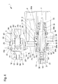
Figure 1 is a diagram representing the hydraulic connections of the device according to the invention; -
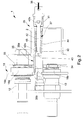
Figure 2 is a side elevation view, partially sectioned, of a device according to the invention with the locking element in the release position; -
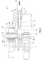
Figure 3 is a side elevation view, partially sectioned, of the device offigure 2 with the locking element in the fastening position; -
Figure 4 is a sectional view of the device ofFigure 2 , with the male couplings arranged externally to the relative female couplings; -
Figure 5 is a sectional view of the coupling ofFigure 2 , with the male couplings in a first position of insertion inside the relative female couplings; -
Figure 6 is a sectional view of the device ofFigure 2 with the male couplings in a second position of insertion inside the relative female couplings; -
Figure 7 is a sectional view of the device ofFigure 2 with the male couplings in the fastening position inside the relative female couplings; -
Figure 8 is a side elevation view of a device according to the invention, having the lever means disengaged from the male couplings; -
Figure 9 is a side elevation view of the device ofFigure 8 with the lever means in engagement with the male couplings. - With particular reference to such figures, globally indicated with reference number 1 is a coupling for the towing vehicle-trailer connection.
- The device 1 comprises a
base body 2 associable with a trailer (not shown in the illustrations) and wherein is defined at least a firstfemale coupling 3, communicating with acontrol line 4 connectable to thebraking system 5 of the trailer, and at least a secondfemale coupling 6, communicating with at least anadditional line 7 connectable to the parking and/orautomatic brake 8 of the trailer itself and with at least a by-pass line 9 connectable to anunloading tank 10. - More particularly, the
control line 4 is able to supply thebraking system 5 of the trailer with a working fluid at a pressure generally between 0 and 150 bar, while theadditional line 7 is able to supply acommand device 11 of the parking and/orautomatic brake 8 at a pressure generally between 15 and 35 bar in such a way as to maintain the parking brake itself open, or deactivated. - The device 1 then comprises also a first and a second male couplings, identified with
reference numbers braking system 14 of the towing vehicle, and in particular are connectable to valves which are able to send, respectively, a first and a second control signal to the trailer. As is known to experts in the sector, these control signals are pressure signals, i.e., they correspond to the sending of the working fluid towards the first andsecond male couplings - More in detail, the first
male coupling 12 is able to transmit a first pressure signal for operating the brakes of the trailer while thesecond male coupling 13 is able to send to the trailer a second substantially constant-pressure signal contained within a predefined range. - In a particular embodiment, not shown in the illustrations, the
body 2 also comprises at least a thirdfemale coupling 70 intended to receive at least a thirdmale coupling 71 connectable, e.g., to an unloading tank not shown in the illustrations. - Preferably, the
tank 10 is of the dynamic type, e.g. of the membrane or spring type, or is able to apply a low backpressure on the working fluid incoming from the by-pass line 9 and is communicating with thecontrol line 4. - The device 1 comprises valve means 17 able to selectively put in communication and isolate between them the
additional line 7 and the by-pass line 9 respectively, as a result of the exit and insertion of thesecond male coupling 13 within the secondfemale couplings 6. - It follows, therefore, that as soon as the
male couplings female couplings additional line 7 is placed in communication with the by-pass line 9, by means of the valve means 17, through which the working fluid contained inside it is unloaded into thetank 10, and so the pressure of the working fluid acting on thecommand device 11 of theparking brake 8 is reduced thus causing the automatic operation of the same. - More in detail, the
command device 11 has two work positions, of which a deactivation position and an activation position of the parking and/or automatic brake and elastic means counteracting the displacement thereof from the activation to the deactivation position. - The
additional line 7 is therefore able to send fluid under pressure to thecommand device 11 when thesecond male coupling 13 is inserted within the secondfemale coupling 6 so as to compress the elastic means of the command device itself and maintain it in the deactivation position. Following the coming out of thesecond male coupling 13 from the secondfemale coupling 6 the fluid under pressure present in theadditional line 7 is unloaded through the by-pass line 9 so that thecommand device 11 is pushed by its elastic means in the activation position. - The valve means 17 comprise at least a first
tubular element 26 inserted in a sliding manner within the secondfemale coupling 6 to open/close theconnection gap 27 between theadditional line 7 and the by-pass line 9. - The first
tubular element 26 is movable between a release configuration, which corresponds to the position taken by the same following the coming out of the secondmale coupling 13 from the secondfemale joint 6 and wherein theadditional line 7 is placed in communication with the by-pass line 9, and a fastening configuration, wherein the additional line and the by-pass line 9 are mutually isolated. The firsttubular element 26 has a plurality of intermediate configurations, which occur following the insertion of the secondmale coupling 13 within the secondfemale coupling 6 up to the locking of the same, and in which the first tubular element itself interrupts the connection between theadditional line 7 and the by-pass line 9. - In the fastening configuration the working fluid present in the
additional line 7 is sent to thecommand device 11 to maintain it in the deactivation position, while in the release configuration the working fluid present in theadditional line 7 is unloaded through the by-pass line 9 so that the pressure acting on the elastic means of thecommand device 11 decreases progressively and the latter is pushed by the elastic means themselves in the activation position. - The
second male coupling 13, in turn, defines afirst channel 31 of the working fluid and has afirst closing element 32 of the first channel itself movable between a relative opening configuration and a relative closing configuration. Conveniently,elastic means 51 are provided able to counteract the displacement of thefirst closing element 32 to the opening configuration. - The valve means 17 also comprise a second
tubular element 28 inserted in a sliding manner within the firsttubular element 26 and defining asecond channel 29 for the transit of the working fluid, there being provided asecond closing element 30 of the second channel itself. - The second
tubular element 28 is movable with respect to thesecond closing element 30 between a closing configuration and an opening configuration of thesecond channel 29. - As a result of the insertion of the second
male coupling 13 within the secondfemale coupling 6, thefirst closing element 32 is able to contact thesecond closing element 30 by displacing from the closing configuration to the opening configuration, and the end of the second male coupling itself is able to contact the firsttubular element 26 to displace it to the fastening configuration. The firsttubular element 26 is able to drag in its displacement the secondtubular element 28 to displace it to the relative opening configuration in order to place in communication the first with thesecond channels - Preferably, the
second male coupling 13 comprises first sealing means 52 able to cooperate with thefirst closing element 32 when the latter is in the closing configuration and able to cooperate with the secondtubular element 28 as a result of the insertion of the secondmale coupling 13 within the secondfemale coupling 6. The first sealing means 52 are arranged at the inner wall of thesecond male coupling 13 delimiting thefirst channel 31. - The
second closing element 30 then comprises second sealing means 53 able to cooperate with the firsttubular element 26 in its closing configuration. Suitably, the end portion of thesecond closing element 30 facing the secondmale coupling 13 has a conformation diverging outwards, e.g. of the frustoconical shape. - Advantageously, the first and second
tubular elements abutment surface 26a and acounter-abutment surface 28a arranged facing one another. Theabutment surface 26a is spaced from thecounter-abutment surface 28a in the release configuration of the firsttubular element 26, while it is able to contact it as a result of the displacement of the first tubular element itself to the fastening configuration. - Between the first
tubular element 26 and thebody 2 are placed first elastic means 54 able to counteract the displacement of the first tubular element itself to the fastening configuration. - Second
elastic means 55 are also placed between the secondtubular element 28 and thebody 2 and able to counteract the displacement of the second tubular element itself to the opening configuration. - Preferably, the device 1 comprises at least a
sealing element 56 associated with thebody 2 and arranged downstream, with respect to the direction of insertion of thesecond male coupling 13 within the secondfemale coupling 6, of theconnection gap 27 between theadditional line 7 and the by-pass line 9. This sealingelement 56 is able to be contacted by the firsttubular element 26 following the insertion of thesecond male coupling 13 within the secondfemale coupling 6. - Conveniently, the first
tubular element 26 is able to contact thesealing element 56 before dragging in its displacement the secondtubular element 28. More particularly, the firsttubular element 26 is able to contact thesealing element 56 before theabutment surface 26a contacts thecounter-abutment surface 28a to drag the secondtubular element 28 in translation. Thesecond channel 29 is therefore able to open after the firsttubular element 26 achieves the fastening configuration. - More particularly, the sealing
element 56 is arranged resting against thebody 2 and defines afirst groove 56a facing theadditional line 7 and at least asecond groove 56b facing thebody 2, where suchsecond groove 56b is communicating with the by-pass line 9 as a result of the contact of thesealing element 56 with the firsttubular element 26. It follows, therefore, that thefirst groove 56a is subject to a pressure greater than that acting on thesecond groove 56b, therefore the sealingelement 56 is pushed towards the walls of thebody 2 so as to remain in place even after the return of the firsttubular element 26 to the release configuration. - As can be easily understood, also the first
male coupling 12 has afirst duct 57 for the transit of the working fluid and athird closing element 58 of the first duct itself, which is movable between an opening and a closing configuration. Suitably,elastic means 59 are provided able to counteract the displacement of thethird closing element 58 to the opening configuration. - More particularly, the
third closing element 58 is arranged at the axial extremity of thefirst duct 57 facing the firstfemale coupling 3. - The
third closing element 58 also comprises third sealing means 60 able to cooperate with the inner wall of thefirst male coupling 12 delimiting thefirst duct 57 in the closing configuration. - Within the first
female coupling 3 is arranged a furthertubular element 61 defining asecond duct 62 for the transit of the working fluid and afourth closing element 63 of the second duct itself, which is movable between a relative closing configuration and a relative opening configuration. Suitably,elastic means 64 are provided able to counteract the displacement of thefourth closing element 63 to its opening configuration. - In the embodiment shown in the illustrations, the further
tubular element 61 has a plurality ofopenings 65 arranged at its side surface and thefourth closing element 63 is fitted externally to the furthertubular element 61 so as to obstruct theopenings 65 in its closing configuration. - Following the insertion of the first
male coupling 12 within the firstfemale coupling 3, thethird closing element 58 contacts the extremity of the furthertubular element 61, moving towards its closing configuration, and the end of the firstmale coupling 12 is able to contact thefourth closing element 63 to move it to its opening configuration, so as to make theopenings 65 accessible and place in communication thefirst duct 57 with thesecond duct 62. - The device 1 also comprises a
connection element 18 which has at least afirst ring nut 18a fitted around the firstfemale coupling 3 and at least asecond ring nut 18b fitted around the secondfemale coupling 6, where the first and thesecond ring nuts plate 18c. - The
connection element 18 is movable with respect to thebody 2 between an unlocking position, wherein it allows the displacement of themale couplings female couplings - According to the invention fastening and release means are also provided able to cooperate with one another to allow the locking and unlocking of the
male couplings female couplings connection element 18 achieving the locking position and the unlocking position, respectively. - Advantageously, the fastening and release means comprise at least two locking
elements 21 each of which is associated with thebody 2 at a relativefemale coupling male couplings female coupling connection element 18 being able to keep the lockingelements 21 engaged with the relativemale couplings - More in particular, the fastening and release means comprise at least a
first recess 22 defined on eachring nut second recess 23 defined on eachmale coupling - The locking
elements 21 are positioned within a relative throughhole 24 defined on thebody 2, which contain them laterally, and are able to be inserted within the corresponding second recesses 23 as a result of the insertion of themale couplings female couplings - The
connection element 18 in its locking position keeps pressed the lockingelements 21 within the second recesses 23, while in its unlocking position thefirst recesses 22 are arranged at the locking elements themselves thus allowing the coming out of themale couplings female couplings - More in detail, in the locking position of the
connection element 18 thelocking elements 21 rest against arelative locator surface 25 defined by the connection element itself and which prevents its displacement from the relativesecond recess 23, while in the unlocking position of theconnection element 18, thefirst recesses 22, by arranging themselves at therelative locking elements 21, allow the latter to come out of the relative second recesses 23. - In the embodiment represented in the illustrations, the locking
elements 21 are of the ball type and the first andsecond recesses - Advantageously, elastic means 33, 34 are placed between the
body 2 and theconnection element 18 and able to counteract the displacement of the latter from the locking position to the unlocking position. - More in particular, the elastic means 33, 34 comprise first elastic means 33 interposed between the
body 2 and thefirst ring nut 18a and second elastic means 34 interposed between thebody 2 and thesecond ring nut 18b. Preferably, guide means 35 are provided of the displacement of theconnection element 18 between the locking position and the unlocking position. The guide means 35 comprise aguide element 35a locked together with theconnection element 18, and in particular with theplate 18c, and inserted sliding inside aseat 35b obtained within thebody 2. Theseat 35b also defines an end-of-stroke surface against which theguide element 35a rests after theconnection element 18 has reached the unlocking position. - In the embodiment shown in the illustrations, the
guide element 35a is placed between the first and thesecond ring nuts - The guide means 35 are therefore able to keep the
plate 18c substantially orthogonal to the axes of thefemale couplings connection element 18 between the locking position and the unlocking position. - Advantageously, the device 1 comprises lever means 66, shown in the
illustrations body 2 and able to act on themale couplings female couplings - More in detail, the lever means 66, e.g. hook-shaped, are able to act on a
pin 67 locked together with themale couplings connection element 18 moves from the unlocking position to the locking position. - The device 1 also comprises emergency means 36 able to control the displacement of the
connection element 18 from the locking position to the unlocking position as a result of the application of a predefined force on the emergency means themselves. - More in detail, the emergency means 36 comprise at least an
actuating element 37 mechanically connected to theconnection element 18 and movable with respect to thebody 2 between an idle configuration, wherein theconnection element 18 can be moved between the locking position and the unlocking position, and an emergency configuration, wherein it is displaced with respect to the idle configuration and drags theconnection element 18 to the unlocking position. - The
actuating element 37 is connected to a flexible pullingelement 38, of the type of an inextensible cable or a rope, connectable on the opposite side to the trailer. The pullingelement 38 is able to move theactuating element 37 with respect to thebody 2 as a result of the achievement of the above predefined force. For example, in case of the trailer's tow bar breaking, the pullingelement 38 is tensioned by applying a force on theactuating element 37. - In the preferred embodiment shown in the illustrations, the
actuating element 37 is associated with theguide element 35a, which is movable in translation with respect to the actuating element itself, with the latter in the idle confguration, to displace theconnection element 18 from the locking position to the unlocking position. - More in detail, the
guide element 35a is internally hollow and theactuating element 37 inserts inside it and defines alocator element 40 able to contact the guide element itself following the displacement from the idle configuration to the emergency configuration. - The emergency means 36 then comprise a joint 41 associated with the
actuating element 37 on opposite side of thelocator element 40 and connected to the pullingelement 38. The joint 41 is therefore able to allow the transfer of the force from the pullingelement 38 to theactuating element 37 also in case of a misalignment of same. In particular, the joint 41 is able to rotate with respect to theactuating element 37 by a predefined angle. The ends of stroke of the rotation of the joint 41 with respect to theactuating element 37 are defined by the resting of the joint itself against thebody 2. In other words, as a result of the rotation of the joint 41 with respect to theactuating element 37, the joint itself rests against thebody 2 and the contact area acts as a fulcrum to allow the transfer of force to the actuating element itself. - More in particular, the
actuating element 37 comprises atie rod 42 inserted through thebody 2 and which has afirst extremity 42a, with which anut 43 is associated which inserts within theguide element 35a and the head of which defines thelocator element 40, and asecond extremity 42b that protrudes from the body itself and with which the joint 41 is associated. - Conveniently, the emergency means 36 comprise further elastic means 44 placed between the actuating
element 37 and thebody 2 and able to counteract the displacement of the actuating element itself from the idle configuration to the emergency configuration. The furtherelastic means 44 are, e.g., of the type of a pre-compressed helical spring, inserted within aseat 45 obtained in thebody 2 and having an extremity that interacts with thetie rod 42, the latter sliding within theseat 45 by effect of the movement of theactuating element 37, and the opposite extremity which rests against thebody 2 or against an element locked with it. - The operation of the present invention is as follows.
- Until the
male couplings female couplings ducts channels relative closing elements - The first
tubular element 26 is therefore arranged in the release configuration, therefore theadditional line 7 is placed in communication with the by-pass line 9, It follows, therefore, that the working fluid present in theadditional line 7 is sent to thetank 10 and that the elastic means 11 a not being counteracted by the pressure present in the additional line itself move thecommand device 11 to the activation position. - Following the insertion of the
male couplings female couplings closing elements relative ducts relative channels - More particularly, the axial extremity of the further
tubular element 61 pushes thethird closing element 58 in contrast to the elastic means 59 to an opening configuration, which is achieved when the third sealing means 60 deviate from the relative inner wall of the firstmale coupling 12 by opening thefirst duct 57. At the same time, the axial extremity of the firstmale coupling 12 pushes thefourth closing element 63 in contrast to the elastic means 64 so as to free theopenings 65. - When the third sealing means 60 are spaced from the inner wall of the first
male coupling 12 and thefourth closing element 63 is in an opening configuration, the working fluid can flow from thefirst duct 57 to thesecond duct 62. Similarly, following the insertion of the secondmale coupling 13 within the secondfemale coupling 6, thefirst closing element 32 is pushed towards its opening configuration in contrast to the elastic means 51 due to the contact with thesecond closing element 30. At the same time, the axial extremity of the secondmale coupling 13 contacts the firsttubular element 26, pushing it from the release configuration to the fastening configuration in contrast to the firstelastic means 54. Following this displacement, the firsttubular element 26, which in the meantime obstructs theconnection gap 27 isolating theadditional line 7 from the by-pass line 9, contacts with itsabutment surface 26a thecounter-abutment surface 28a of the secondtubular element 28, so as to drag the latter away from the end portion of thesecond closing element 30 in contrast to the secondelastic means 55. The firsttubular element 26 performs a stretch of stroke during which the secondtubular element 28 remains stationary, the lenght of which depends on the distance of thesurfaces second channel 29. - When the first sealing means 52 are detached from the
first closing element 32 and move resting against the external surface of the secondtubular element 28 and the latter is detached from the second sealing means 53, the first and thesecond channels braking system 14 of the towing vehicle reaches theadditional line 7 so as to maintain compressed the elastic means 11 a and, consequently, thecommand device 11 in the deactivation position of the parking and/orautomatic brake 8. - When the
male couplings female couplings connection element 18 is in the unlocking position and is maintained in this position by the lockingelement 21 arranged at the secondfemale coupling 6, which is maintained within the relativefirst recess 22 by the firsttubular element 26, the latter being arranged in idle configuration. - The
second ring nut 18b is thus locked with respect to the secondfemale coupling 6 in release position and also locks consequently thefirst ring nut 18a, which, on the contrary, would be free to move to the fastening position by effect of the force applied by theelastic means 33. - In this work configuration, the
connection element 18 is then maintained in the unlocking position and the elastic means 33 and 34 are compressed. - Following the insertion of the
male couplings female couplings second recesses 23 defined on the pins themselves approach the lockingelements 21. As soon as thesecond recesses 23 arrive at the lockingelements 21, the latter are inserted, by effect of their own weight, within the second recesses themselves, consequently freeing theconnection element 18 which is pushed by the elastic means 33, 34 into the locking position. - The insertion of the
male couplings female couplings - In this work configuration, the
male couplings female couplings elements 21 are maintained within the relativesecond recesses 23 by the locator surfaces 25 defined by theconnection element 18. - To remove the
male couplings female couplings connection element 18 must return to the unlocking position, so that the lockingelements 21 can be moved within the relativefirst recesses 22 by effect of the coming out of the male couplings themselves from the relative female couplings. - The displacement of the
connection element 18 from the locking position to the unlocking position can be made manually by acting on theplate 18c. - As mentioned above, in case of the trailer's tow bar breaking or the trailer itself not being fastened properly, the pulling
element 38 becomes tensioned by applying a force on theactuating element 37 by means of the joint 41. - In particular, in the event of the pulling
element 38 being misaligned with respect to theactuating element 37, the joint 41 rotates with respect to theactuating element 37 until it rests against thebody 2 to transfer the tensile force onto the actuating element itself. - As soon as the force applied on the
actuating element 37 reaches the intensity corresponding to the preloading of the furtherelastic means 44, the latter begin to compress and the actuating element itself begins to shift from the idle configuration to the emergency configuration. - During this displacement, the
locator element 40 drags, acting on theguide element 35a, theconnection element 18, which is in the fastening position, themale couplings female couplings - In practice it has been ascertained how the described invention achieves the proposed objects and in particular the fact is underlined that the coupling forming the subject of the present invention ensures the unloading of the working fluid present in the additional line following the coming out of the pins from their seats by means of an embodiment which is simple from a constructive viewpoint and reliable in operation.
Claims (12)
- Device (1) for the towing vehicle-trailer connection, characterized in that it comprises:- a base body (2) associable with a trailer and wherein is defined at least a first female coupling (3), communicating with a control line (4) connectable to the braking system (5) of the trailer, and at least a second female coupling (6), communicating with at least an additional line (7) which acts on the parking brake (8) of the trailer and with at least a by-pass line (9) communicating with an unloading tank (10);- at least a first and a second male couplings (12, 13) associable with a towing vehicle of the trailer and connectable to the relative braking system (14), where said first and second male couplings (12, 13) are connectable to valves able to send to the same, respectively, a working fluid at a first and at a second pressure and are insertable, respectively within said first and second female couplings (3, 6); where said second male coupling (13) defines a first channel (31) for the transit of a working fluid and has a first closing element (32) of said first transit channel (31) movable between an opening configuration and a closing configuration,- valve means (17) able to put in communication and isolate between them said additional line (7) with said by-pass line (9), respectively, as a result of the exit and the insertion of said male couplings (12, 13) from the relative female couplings (3, 6);
and where said valve means (17) comprise a first tubular element (26) movable in a sliding manner within said second female coupling (6) between a release configuration, wherein said additional line (7) and said by-pass line (9) are mutually communicating, and a fastening configuration, wherein said additional line (7) and said by-pass line (9) are mutually isolated, a second tubular element (28) inserted in a sliding manner within said first tubular element (26) and defining a second channel (29) for the transit of the working fluid, there being provided a second closing element (30) of the second channel itself, said second tubular element (28) being movable with respect to the second closing element itself between a closing configuration and an opening configuration of said second transit channel (29);
and characterized in that as a result of the insertion of said second male coupling (13) within said second female coupling (6), said second closing element (30) is able to contact said first closing element (32) to displace it from the closing configuration to the opening configuration, and the end of the second male coupling itself is able to contact said first tubular element (26) to displace it to said fastening configuration, said first tubular element (26) being able to drag in its displacement said second tubular element (28) to displace it to the relative opening configuration in order to place in communication said first and second transit channels (31, 29) together. - Device (1) according to claim 1, characterized in that said first and second tubular elements (26, 28) have, respectively, an abutment surface (26a) and a counter-abutment surface (28a) arranged facing one another, said abutment surface (26a) being spaced from said counter-abutment surface (28a) in the release configuration and being able to contact it as a result of the displacement of said first tubular element (26) to the fastening configuration.
- Device (1) according to claim 2, characterized in that said abutment surface (26a) is able to contact said counter-abutment surface (28a) as a result of the achievement of the fastening configuration by said first tubular element (26).
- Device (1) according to one or more of the preceding claims, characterized in that it comprises first elastic means (54) placed between said first tubular element (26) and said body (2) and able to counteract the displacement of the first tubular element itself to the fastening configuration.
- Device (1) according to one or more of the preceding claims, characterized in that it comprises second elastic means (55) placed between said second tubular element (28) and said body (2) and able to counteract the displacement of the second tubular element itself to the relative opening configuration.
- Device (1) according to one or more of the preceding claims, characterized in that said second male coupling (13) comprises first sealing means (52) able to cooperate with said first closing element (32) when the latter is in closing configuration and able to cooperate with said second tubular element (28) as a result of the insertion of the second male coupling itself within said second female coupling (6).
- Device (1) according to one or more of the preceding claims, characterized in that said second closing element (30) comprises second sealing means (53) able to cooperate with said first tubular element (26) in its closing configuration.
- Device (1) according to one or more of the preceding claims, characterized in that the end portion of said second closing element (30) facing said second male coupling (13) has a conformation diverging outwards.
- Device (1) according to one or more of the preceding claims, characterized in that said base body (2) comprises at least a third female coupling and in that it comprises a third male coupling able to be inserted within said third female coupling.
- Device (1) according to one or more of the preceding claims, characterized in that it comprises at least a sealing element (56) associated with said body (2) and arranged downstream, with respect to the direction of insertion of said second male coupling (13) within said second female coupling (6), of the connection gap (27) between said additional line (7) and said by-pass line (9), said first tubular element (26) being able to contact said sealing element (56) in its displacement to the fastening configuration to mutually isolate said additional line (7) and said by-pass line (9).
- Device (1) according to claim 10, characterized in that said first tubular element (26) is able to drag in its displacement said second tubular element (28) after the interaction with said sealing element (56).
- Device (1) according to claim 10 or 11, characterized in that said sealing element (56) defines at least a first groove (56a) facing said additional line (7) and at least a second groove (56b) facing a wall of said body (2), as a result of the achievement of the fastening configuration by said first tubular element (26), said second groove (56b) being placed in communication with said by-pass line (9) and the pressure applying on it being less than that applying on said first groove (56a).
Applications Claiming Priority (1)
| Application Number | Priority Date | Filing Date | Title |
|---|---|---|---|
| ITMO20140159 | 2014-05-30 |
Publications (2)
| Publication Number | Publication Date |
|---|---|
| EP2955073A1 true EP2955073A1 (en) | 2015-12-16 |
| EP2955073B1 EP2955073B1 (en) | 2018-06-20 |
Family
ID=51265766
Family Applications (1)
| Application Number | Title | Priority Date | Filing Date |
|---|---|---|---|
| EP15169967.5A Active EP2955073B1 (en) | 2014-05-30 | 2015-05-29 | Device for the towing vehicle-trailer connection |
Country Status (1)
| Country | Link |
|---|---|
| EP (1) | EP2955073B1 (en) |
Cited By (2)
| Publication number | Priority date | Publication date | Assignee | Title |
|---|---|---|---|---|
| EP3266661A1 (en) * | 2016-07-05 | 2018-01-10 | Paul Forrer AG | Trailer brake system and operating methods for a trailer brake system |
| IT202300027060A1 (en) * | 2023-12-18 | 2025-06-18 | Slanzi Oleodinamica S R L | DEVICE FOR CONTROLLING THE BRAKING OF A TRAILER |
Citations (7)
| Publication number | Priority date | Publication date | Assignee | Title |
|---|---|---|---|---|
| FR2268674A1 (en) * | 1974-04-24 | 1975-11-21 | Bosch Gmbh Robert | Pressure control valve for trailer pneumatic brakes - isolates trailer supply when trailer brake line broken, for hold-off brake operation |
| EP0167968A2 (en) * | 1984-07-07 | 1986-01-15 | Dietrich Neumann | Coupling head for fluid lines of fluid pressure brake installations in vehicles |
| DE202006016234U1 (en) * | 2006-10-19 | 2007-02-01 | Ringfeder Vbg Gmbh | Manual rapid connection element for vehicle electrics between vehicle and trailer has locking element to lock and unlock connecting element having both electrical and pneumatic or hydraulic connections |
| WO2012095389A2 (en) * | 2011-01-11 | 2012-07-19 | Knorr-Bremse Systeme für Nutzfahrzeuge GmbH | Coupling head arrangement for connecting a trailer to a towing vehicle |
| EP2591963A1 (en) * | 2011-11-11 | 2013-05-15 | Studio Tecnico 6 M S.R.L. | Device for braking a trailer |
| EP2610122A1 (en) * | 2011-12-28 | 2013-07-03 | KNORR-BREMSE Systeme für Nutzfahrzeuge GmbH | Coupling head |
| EP2631131A2 (en) * | 2012-02-24 | 2013-08-28 | Haldex Brake Products GmbH | Agricultural tractor |
-
2015
- 2015-05-29 EP EP15169967.5A patent/EP2955073B1/en active Active
Patent Citations (7)
| Publication number | Priority date | Publication date | Assignee | Title |
|---|---|---|---|---|
| FR2268674A1 (en) * | 1974-04-24 | 1975-11-21 | Bosch Gmbh Robert | Pressure control valve for trailer pneumatic brakes - isolates trailer supply when trailer brake line broken, for hold-off brake operation |
| EP0167968A2 (en) * | 1984-07-07 | 1986-01-15 | Dietrich Neumann | Coupling head for fluid lines of fluid pressure brake installations in vehicles |
| DE202006016234U1 (en) * | 2006-10-19 | 2007-02-01 | Ringfeder Vbg Gmbh | Manual rapid connection element for vehicle electrics between vehicle and trailer has locking element to lock and unlock connecting element having both electrical and pneumatic or hydraulic connections |
| WO2012095389A2 (en) * | 2011-01-11 | 2012-07-19 | Knorr-Bremse Systeme für Nutzfahrzeuge GmbH | Coupling head arrangement for connecting a trailer to a towing vehicle |
| EP2591963A1 (en) * | 2011-11-11 | 2013-05-15 | Studio Tecnico 6 M S.R.L. | Device for braking a trailer |
| EP2610122A1 (en) * | 2011-12-28 | 2013-07-03 | KNORR-BREMSE Systeme für Nutzfahrzeuge GmbH | Coupling head |
| EP2631131A2 (en) * | 2012-02-24 | 2013-08-28 | Haldex Brake Products GmbH | Agricultural tractor |
Cited By (3)
| Publication number | Priority date | Publication date | Assignee | Title |
|---|---|---|---|---|
| EP3266661A1 (en) * | 2016-07-05 | 2018-01-10 | Paul Forrer AG | Trailer brake system and operating methods for a trailer brake system |
| IT202300027060A1 (en) * | 2023-12-18 | 2025-06-18 | Slanzi Oleodinamica S R L | DEVICE FOR CONTROLLING THE BRAKING OF A TRAILER |
| EP4574596A1 (en) * | 2023-12-18 | 2025-06-25 | Slanzi Oleodinamica S.r.l. | Device for controlling the braking of a trailer |
Also Published As
| Publication number | Publication date |
|---|---|
| EP2955073B1 (en) | 2018-06-20 |
Similar Documents
| Publication | Publication Date | Title |
|---|---|---|
| CN111497888B (en) | Automatic traction connector | |
| EP3000631B1 (en) | Device for the towing vehicle-trailer connection | |
| US10501099B2 (en) | Rail vehicle braking system and braking method for a rail vehicle comprising such a system | |
| EP2955073B1 (en) | Device for the towing vehicle-trailer connection | |
| US6431329B1 (en) | Fluid parking brake for a rail vehicle air brake cylinder | |
| CN104044417A (en) | Driving brake traction device for full trailer | |
| WO2005081901A3 (en) | Remotely releasable coupler and hose retrieval mechanism for airbrake system | |
| US4268071A (en) | Device for coupling pipeline flanges | |
| EP2962912A2 (en) | Braking device | |
| EP3225473B1 (en) | Device for the control of the braking of a trailer | |
| EP3000672B1 (en) | Valve assembly for trailer | |
| US5683148A (en) | Brake pipe pneumatic valve | |
| EP3085590B1 (en) | Device for controlling the braking of a trailer | |
| EP2952398B1 (en) | Valve assembly | |
| EP3515764B1 (en) | A system preventing the activation of a trailer's overrun brakes during reversing | |
| EP3368385B1 (en) | Braking device for trailers of agricultural machines | |
| EP3165385B1 (en) | Device for the towing vehicle-trailer connection | |
| US2362324A (en) | Brake for trailers and the like | |
| EP3650293B1 (en) | Device for controlling the braking of a trailer | |
| EP4574596A1 (en) | Device for controlling the braking of a trailer | |
| US10507808B2 (en) | System for preventing a trailer's overrun brakes from being activated during reversing | |
| EP3611063B1 (en) | Tractor-trailer connection device | |
| WO2016204607A1 (en) | Safety coupling device provided with shut-off valves for coupling two fluid conduit parts | |
| US20070296267A1 (en) | Apparatus for braking systems of articulated vehicles | |
| US2086381A (en) | Train line coupler |
Legal Events
| Date | Code | Title | Description |
|---|---|---|---|
| PUAI | Public reference made under article 153(3) epc to a published international application that has entered the european phase |
Free format text: ORIGINAL CODE: 0009012 |
|
| AK | Designated contracting states |
Kind code of ref document: A1 Designated state(s): AL AT BE BG CH CY CZ DE DK EE ES FI FR GB GR HR HU IE IS IT LI LT LU LV MC MK MT NL NO PL PT RO RS SE SI SK SM TR |
|
| AX | Request for extension of the european patent |
Extension state: BA ME |
|
| 17P | Request for examination filed |
Effective date: 20160601 |
|
| RBV | Designated contracting states (corrected) |
Designated state(s): AL AT BE BG CH CY CZ DE DK EE ES FI FR GB GR HR HU IE IS IT LI LT LU LV MC MK MT NL NO PL PT RO RS SE SI SK SM TR |
|
| GRAP | Despatch of communication of intention to grant a patent |
Free format text: ORIGINAL CODE: EPIDOSNIGR1 |
|
| STAA | Information on the status of an ep patent application or granted ep patent |
Free format text: STATUS: GRANT OF PATENT IS INTENDED |
|
| INTG | Intention to grant announced |
Effective date: 20171121 |
|
| RAP1 | Party data changed (applicant data changed or rights of an application transferred) |
Owner name: STUDIO TECNICO 6 M S.R.L. |
|
| GRAS | Grant fee paid |
Free format text: ORIGINAL CODE: EPIDOSNIGR3 |
|
| 111Z | Information provided on other rights and legal means of execution |
Free format text: AL AT BE BG CH CY CZ DE DK EE ES FI FR GB GR HR HU IE IS IT LT LU LV MC MK MT NL NO PL PT RO RS SE SI SK SM TR Effective date: 20180208 |
|
| RAP1 | Party data changed (applicant data changed or rights of an application transferred) |
Owner name: SAFIM S.P.A. |
|
| RIN1 | Information on inventor provided before grant (corrected) |
Inventor name: MAMEI, ENRICO Inventor name: MAMEI, ERONNE Inventor name: MAMEI, ANDREA |
|
| GRAA | (expected) grant |
Free format text: ORIGINAL CODE: 0009210 |
|
| STAA | Information on the status of an ep patent application or granted ep patent |
Free format text: STATUS: THE PATENT HAS BEEN GRANTED |
|
| AK | Designated contracting states |
Kind code of ref document: B1 Designated state(s): AL AT BE BG CH CY CZ DE DK EE ES FI FR GB GR HR HU IE IS IT LI LT LU LV MC MK MT NL NO PL PT RO RS SE SI SK SM TR |
|
| REG | Reference to a national code |
Ref country code: GB Ref legal event code: FG4D |
|
| REG | Reference to a national code |
Ref country code: IE Ref legal event code: FG4D |
|
| REG | Reference to a national code |
Ref country code: AT Ref legal event code: REF Ref document number: 1010364 Country of ref document: AT Kind code of ref document: T Effective date: 20180715 |
|
| REG | Reference to a national code |
Ref country code: DE Ref legal event code: R096 Ref document number: 602015012444 Country of ref document: DE |
|
| REG | Reference to a national code |
Ref country code: NL Ref legal event code: MP Effective date: 20180620 |
|
| PG25 | Lapsed in a contracting state [announced via postgrant information from national office to epo] |
Ref country code: BG Free format text: LAPSE BECAUSE OF FAILURE TO SUBMIT A TRANSLATION OF THE DESCRIPTION OR TO PAY THE FEE WITHIN THE PRESCRIBED TIME-LIMIT Effective date: 20180920 Ref country code: FI Free format text: LAPSE BECAUSE OF FAILURE TO SUBMIT A TRANSLATION OF THE DESCRIPTION OR TO PAY THE FEE WITHIN THE PRESCRIBED TIME-LIMIT Effective date: 20180620 Ref country code: LT Free format text: LAPSE BECAUSE OF FAILURE TO SUBMIT A TRANSLATION OF THE DESCRIPTION OR TO PAY THE FEE WITHIN THE PRESCRIBED TIME-LIMIT Effective date: 20180620 Ref country code: SE Free format text: LAPSE BECAUSE OF FAILURE TO SUBMIT A TRANSLATION OF THE DESCRIPTION OR TO PAY THE FEE WITHIN THE PRESCRIBED TIME-LIMIT Effective date: 20180620 Ref country code: NO Free format text: LAPSE BECAUSE OF FAILURE TO SUBMIT A TRANSLATION OF THE DESCRIPTION OR TO PAY THE FEE WITHIN THE PRESCRIBED TIME-LIMIT Effective date: 20180920 |
|
| REG | Reference to a national code |
Ref country code: LT Ref legal event code: MG4D |
|
| PG25 | Lapsed in a contracting state [announced via postgrant information from national office to epo] |
Ref country code: RS Free format text: LAPSE BECAUSE OF FAILURE TO SUBMIT A TRANSLATION OF THE DESCRIPTION OR TO PAY THE FEE WITHIN THE PRESCRIBED TIME-LIMIT Effective date: 20180620 Ref country code: LV Free format text: LAPSE BECAUSE OF FAILURE TO SUBMIT A TRANSLATION OF THE DESCRIPTION OR TO PAY THE FEE WITHIN THE PRESCRIBED TIME-LIMIT Effective date: 20180620 Ref country code: HR Free format text: LAPSE BECAUSE OF FAILURE TO SUBMIT A TRANSLATION OF THE DESCRIPTION OR TO PAY THE FEE WITHIN THE PRESCRIBED TIME-LIMIT Effective date: 20180620 Ref country code: GR Free format text: LAPSE BECAUSE OF FAILURE TO SUBMIT A TRANSLATION OF THE DESCRIPTION OR TO PAY THE FEE WITHIN THE PRESCRIBED TIME-LIMIT Effective date: 20180921 |
|
| REG | Reference to a national code |
Ref country code: AT Ref legal event code: MK05 Ref document number: 1010364 Country of ref document: AT Kind code of ref document: T Effective date: 20180620 |
|
| PG25 | Lapsed in a contracting state [announced via postgrant information from national office to epo] |
Ref country code: NL Free format text: LAPSE BECAUSE OF FAILURE TO SUBMIT A TRANSLATION OF THE DESCRIPTION OR TO PAY THE FEE WITHIN THE PRESCRIBED TIME-LIMIT Effective date: 20180620 |
|
| PG25 | Lapsed in a contracting state [announced via postgrant information from national office to epo] |
Ref country code: SK Free format text: LAPSE BECAUSE OF FAILURE TO SUBMIT A TRANSLATION OF THE DESCRIPTION OR TO PAY THE FEE WITHIN THE PRESCRIBED TIME-LIMIT Effective date: 20180620 Ref country code: RO Free format text: LAPSE BECAUSE OF FAILURE TO SUBMIT A TRANSLATION OF THE DESCRIPTION OR TO PAY THE FEE WITHIN THE PRESCRIBED TIME-LIMIT Effective date: 20180620 Ref country code: CZ Free format text: LAPSE BECAUSE OF FAILURE TO SUBMIT A TRANSLATION OF THE DESCRIPTION OR TO PAY THE FEE WITHIN THE PRESCRIBED TIME-LIMIT Effective date: 20180620 Ref country code: PL Free format text: LAPSE BECAUSE OF FAILURE TO SUBMIT A TRANSLATION OF THE DESCRIPTION OR TO PAY THE FEE WITHIN THE PRESCRIBED TIME-LIMIT Effective date: 20180620 Ref country code: AT Free format text: LAPSE BECAUSE OF FAILURE TO SUBMIT A TRANSLATION OF THE DESCRIPTION OR TO PAY THE FEE WITHIN THE PRESCRIBED TIME-LIMIT Effective date: 20180620 Ref country code: EE Free format text: LAPSE BECAUSE OF FAILURE TO SUBMIT A TRANSLATION OF THE DESCRIPTION OR TO PAY THE FEE WITHIN THE PRESCRIBED TIME-LIMIT Effective date: 20180620 Ref country code: IS Free format text: LAPSE BECAUSE OF FAILURE TO SUBMIT A TRANSLATION OF THE DESCRIPTION OR TO PAY THE FEE WITHIN THE PRESCRIBED TIME-LIMIT Effective date: 20181020 |
|
| PG25 | Lapsed in a contracting state [announced via postgrant information from national office to epo] |
Ref country code: SM Free format text: LAPSE BECAUSE OF FAILURE TO SUBMIT A TRANSLATION OF THE DESCRIPTION OR TO PAY THE FEE WITHIN THE PRESCRIBED TIME-LIMIT Effective date: 20180620 Ref country code: ES Free format text: LAPSE BECAUSE OF FAILURE TO SUBMIT A TRANSLATION OF THE DESCRIPTION OR TO PAY THE FEE WITHIN THE PRESCRIBED TIME-LIMIT Effective date: 20180620 |
|
| REG | Reference to a national code |
Ref country code: DE Ref legal event code: R097 Ref document number: 602015012444 Country of ref document: DE |
|
| PLBE | No opposition filed within time limit |
Free format text: ORIGINAL CODE: 0009261 |
|
| STAA | Information on the status of an ep patent application or granted ep patent |
Free format text: STATUS: NO OPPOSITION FILED WITHIN TIME LIMIT |
|
| 26N | No opposition filed |
Effective date: 20190321 |
|
| PG25 | Lapsed in a contracting state [announced via postgrant information from national office to epo] |
Ref country code: DK Free format text: LAPSE BECAUSE OF FAILURE TO SUBMIT A TRANSLATION OF THE DESCRIPTION OR TO PAY THE FEE WITHIN THE PRESCRIBED TIME-LIMIT Effective date: 20180620 |
|
| PG25 | Lapsed in a contracting state [announced via postgrant information from national office to epo] |
Ref country code: SI Free format text: LAPSE BECAUSE OF FAILURE TO SUBMIT A TRANSLATION OF THE DESCRIPTION OR TO PAY THE FEE WITHIN THE PRESCRIBED TIME-LIMIT Effective date: 20180620 |
|
| PG25 | Lapsed in a contracting state [announced via postgrant information from national office to epo] |
Ref country code: AL Free format text: LAPSE BECAUSE OF FAILURE TO SUBMIT A TRANSLATION OF THE DESCRIPTION OR TO PAY THE FEE WITHIN THE PRESCRIBED TIME-LIMIT Effective date: 20180620 |
|
| REG | Reference to a national code |
Ref country code: DE Ref legal event code: R119 Ref document number: 602015012444 Country of ref document: DE |
|
| REG | Reference to a national code |
Ref country code: CH Ref legal event code: PL |
|
| PG25 | Lapsed in a contracting state [announced via postgrant information from national office to epo] |
Ref country code: LI Free format text: LAPSE BECAUSE OF NON-PAYMENT OF DUE FEES Effective date: 20190531 Ref country code: MC Free format text: LAPSE BECAUSE OF FAILURE TO SUBMIT A TRANSLATION OF THE DESCRIPTION OR TO PAY THE FEE WITHIN THE PRESCRIBED TIME-LIMIT Effective date: 20180620 Ref country code: CH Free format text: LAPSE BECAUSE OF NON-PAYMENT OF DUE FEES Effective date: 20190531 |
|
| REG | Reference to a national code |
Ref country code: BE Ref legal event code: MM Effective date: 20190531 |
|
| PG25 | Lapsed in a contracting state [announced via postgrant information from national office to epo] |
Ref country code: LU Free format text: LAPSE BECAUSE OF NON-PAYMENT OF DUE FEES Effective date: 20190529 |
|
| PG25 | Lapsed in a contracting state [announced via postgrant information from national office to epo] |
Ref country code: TR Free format text: LAPSE BECAUSE OF FAILURE TO SUBMIT A TRANSLATION OF THE DESCRIPTION OR TO PAY THE FEE WITHIN THE PRESCRIBED TIME-LIMIT Effective date: 20180620 |
|
| PG25 | Lapsed in a contracting state [announced via postgrant information from national office to epo] |
Ref country code: IE Free format text: LAPSE BECAUSE OF NON-PAYMENT OF DUE FEES Effective date: 20190529 Ref country code: DE Free format text: LAPSE BECAUSE OF NON-PAYMENT OF DUE FEES Effective date: 20191203 |
|
| PG25 | Lapsed in a contracting state [announced via postgrant information from national office to epo] |
Ref country code: BE Free format text: LAPSE BECAUSE OF NON-PAYMENT OF DUE FEES Effective date: 20190531 |
|
| PG25 | Lapsed in a contracting state [announced via postgrant information from national office to epo] |
Ref country code: PT Free format text: LAPSE BECAUSE OF FAILURE TO SUBMIT A TRANSLATION OF THE DESCRIPTION OR TO PAY THE FEE WITHIN THE PRESCRIBED TIME-LIMIT Effective date: 20181022 |
|
| PG25 | Lapsed in a contracting state [announced via postgrant information from national office to epo] |
Ref country code: CY Free format text: LAPSE BECAUSE OF FAILURE TO SUBMIT A TRANSLATION OF THE DESCRIPTION OR TO PAY THE FEE WITHIN THE PRESCRIBED TIME-LIMIT Effective date: 20180620 |
|
| PG25 | Lapsed in a contracting state [announced via postgrant information from national office to epo] |
Ref country code: MT Free format text: LAPSE BECAUSE OF FAILURE TO SUBMIT A TRANSLATION OF THE DESCRIPTION OR TO PAY THE FEE WITHIN THE PRESCRIBED TIME-LIMIT Effective date: 20180620 Ref country code: HU Free format text: LAPSE BECAUSE OF FAILURE TO SUBMIT A TRANSLATION OF THE DESCRIPTION OR TO PAY THE FEE WITHIN THE PRESCRIBED TIME-LIMIT; INVALID AB INITIO Effective date: 20150529 |
|
| PG25 | Lapsed in a contracting state [announced via postgrant information from national office to epo] |
Ref country code: MK Free format text: LAPSE BECAUSE OF FAILURE TO SUBMIT A TRANSLATION OF THE DESCRIPTION OR TO PAY THE FEE WITHIN THE PRESCRIBED TIME-LIMIT Effective date: 20180620 |
|
| P01 | Opt-out of the competence of the unified patent court (upc) registered |
Effective date: 20230527 |
|
| PGFP | Annual fee paid to national office [announced via postgrant information from national office to epo] |
Ref country code: GB Payment date: 20250527 Year of fee payment: 11 |
|
| PGFP | Annual fee paid to national office [announced via postgrant information from national office to epo] |
Ref country code: IT Payment date: 20250520 Year of fee payment: 11 |
|
| PGFP | Annual fee paid to national office [announced via postgrant information from national office to epo] |
Ref country code: FR Payment date: 20250526 Year of fee payment: 11 |