EP2955011A1 - Method and device for manufacturing a container - Google Patents
Method and device for manufacturing a container Download PDFInfo
- Publication number
- EP2955011A1 EP2955011A1 EP15168688.8A EP15168688A EP2955011A1 EP 2955011 A1 EP2955011 A1 EP 2955011A1 EP 15168688 A EP15168688 A EP 15168688A EP 2955011 A1 EP2955011 A1 EP 2955011A1
- Authority
- EP
- European Patent Office
- Prior art keywords
- sleeve
- cup
- relative position
- cover
- peripheral wall
- Prior art date
- Legal status (The legal status is an assumption and is not a legal conclusion. Google has not performed a legal analysis and makes no representation as to the accuracy of the status listed.)
- Granted
Links
Images


Classifications
-
- B—PERFORMING OPERATIONS; TRANSPORTING
- B31—MAKING ARTICLES OF PAPER, CARDBOARD OR MATERIAL WORKED IN A MANNER ANALOGOUS TO PAPER; WORKING PAPER, CARDBOARD OR MATERIAL WORKED IN A MANNER ANALOGOUS TO PAPER
- B31D—MAKING ARTICLES OF PAPER, CARDBOARD OR MATERIAL WORKED IN A MANNER ANALOGOUS TO PAPER, NOT PROVIDED FOR IN SUBCLASSES B31B OR B31C
- B31D5/00—Multiple-step processes for making three-dimensional articles ; Making three-dimensional articles
- B31D5/0086—Making hollow objects
-
- B—PERFORMING OPERATIONS; TRANSPORTING
- B31—MAKING ARTICLES OF PAPER, CARDBOARD OR MATERIAL WORKED IN A MANNER ANALOGOUS TO PAPER; WORKING PAPER, CARDBOARD OR MATERIAL WORKED IN A MANNER ANALOGOUS TO PAPER
- B31B—MAKING CONTAINERS OF PAPER, CARDBOARD OR MATERIAL WORKED IN A MANNER ANALOGOUS TO PAPER
- B31B2105/00—Rigid or semi-rigid containers made by assembling separate sheets, blanks or webs
-
- B—PERFORMING OPERATIONS; TRANSPORTING
- B31—MAKING ARTICLES OF PAPER, CARDBOARD OR MATERIAL WORKED IN A MANNER ANALOGOUS TO PAPER; WORKING PAPER, CARDBOARD OR MATERIAL WORKED IN A MANNER ANALOGOUS TO PAPER
- B31B—MAKING CONTAINERS OF PAPER, CARDBOARD OR MATERIAL WORKED IN A MANNER ANALOGOUS TO PAPER
- B31B2110/00—Shape of rigid or semi-rigid containers
- B31B2110/10—Shape of rigid or semi-rigid containers having a cross section of varying size or shape, e.g. conical or pyramidal
-
- B—PERFORMING OPERATIONS; TRANSPORTING
- B31—MAKING ARTICLES OF PAPER, CARDBOARD OR MATERIAL WORKED IN A MANNER ANALOGOUS TO PAPER; WORKING PAPER, CARDBOARD OR MATERIAL WORKED IN A MANNER ANALOGOUS TO PAPER
- B31B—MAKING CONTAINERS OF PAPER, CARDBOARD OR MATERIAL WORKED IN A MANNER ANALOGOUS TO PAPER
- B31B2110/00—Shape of rigid or semi-rigid containers
- B31B2110/20—Shape of rigid or semi-rigid containers having a curved cross section, e.g. circular
-
- B—PERFORMING OPERATIONS; TRANSPORTING
- B31—MAKING ARTICLES OF PAPER, CARDBOARD OR MATERIAL WORKED IN A MANNER ANALOGOUS TO PAPER; WORKING PAPER, CARDBOARD OR MATERIAL WORKED IN A MANNER ANALOGOUS TO PAPER
- B31B—MAKING CONTAINERS OF PAPER, CARDBOARD OR MATERIAL WORKED IN A MANNER ANALOGOUS TO PAPER
- B31B50/00—Making rigid or semi-rigid containers, e.g. boxes or cartons
- B31B50/26—Folding sheets, blanks or webs
- B31B50/44—Folding sheets, blanks or webs by plungers moving through folding dies
Definitions
- the invention relates to a method for producing a cup from a conical sleeve and a cup-shaped bottom, wherein the bottom has a bottom surface and an outgoing from the bottom surface peripheral wall and from a larger opening of the conical sleeve forth in the direction of the smaller opening of the sleeve in the sleeve is inserted.
- the invention also relates to a device for producing a cup from a conical sleeve and a cup-shaped bottom, wherein the device for inserting the bottom is formed by a larger opening of the conical sleeve in the direction of the smaller opening of the sleeve in the sleeve.
- the at least partially covering a radially outer peripheral surface of the wall of the cup-shaped bottom with an annular cover sleeve arranging the cover and the bottom in a predefined relative position between the sleeve and the bottom, the extraction of the cover between an inner side of the sleeve and the radially outer peripheral surface of the bottom, wherein the bottom remains in the predefined relative position, and provided the substantially liquid-tight connection of the radially outer circumferential surface of the bottom and the inside of the sleeve.
- an annular cover sleeve between a radially outer peripheral surface of the wall of the cup-shaped bottom and the inside of the sleeve is arranged.
- the cover sleeve when delivering the soil, only the outside of the cover sleeve comes into contact with the inside of the sleeve.
- the outer side of the cover sleeve can be selected with respect to the material or the surface so that the cover sleeve can slide smoothly along the inside of the sleeve. Only when the bottom has reached a predefined relative position to the sleeve, the cover sleeve between the peripheral wall and the inside of the sleeve is pulled out. At this time, the bottom and the sleeve relative to each other but already at rest and at the intended relative position. A possible adhesion of soil and sleeve in this position is thus harmless and even desirable in the subsequent step of liquid-tight bonding.
- the covering sleeve can be delivered together with the ground into the sleeve or the covering sleeve can rest relative to the sleeve and the bottom is pushed into the covering sleeve.
- Particular advantages of the method according to the invention then, if due to the materials of the bottom and sleeve adhesion of the soil to the sleeve in a relative movement is to be feared each other.
- the invention is thus designed in a special way for materials whose surfaces have a high coefficient of friction to each other.
- This can be, for example, coated paper material or coated cardboard, for example, but also paper-like to be processed flat plastic material.
- Flat plastic materials are, for example, also plastic laminates.
- the invention is very well suited for paper-like plastic material to be processed, but not specifically designed for paper-like plastic material to be processed.
- the predefined relative position as seen in the longitudinal direction of the sleeve, corresponds to the relative position of the base and sleeve on the finished cup.
- bottom and sleeve relative to each other must not be moved after the cover sleeve between the peripheral wall of the bottom and the inside of the sleeve has been pulled out. Minor displacements during liquid-tight bonding of the bottom and sleeve are excluded.
- an outer peripheral surface of the cover sleeve is located at least in sections on the inner side of the sleeve or is arranged directly adjacent to the inner side of the sleeve.
- the peripheral wall of the bottom and the inside of the sleeve can be brought very close to each other without being in direct contact.
- the bottom can be arranged under slight bias in the cover sleeve, so that the peripheral wall slightly widened after pulling out of the cover and then the peripheral wall of the bottom rests flat against the inside of the sleeve.
- an apparatus for producing a cup from a conical sleeve and a cup-shaped bottom with the features of claim 5 is provided.
- Advantageous developments of the invention are specified in the subclaims.
- the device for producing a cup from a conical sleeve and a cup-shaped bottom for inserting the bottom of a larger opening of the conical sleeve forth in the direction of the smaller opening of the sleeve is formed in the sleeve.
- the device has an annular cover sleeve whose inner circumference is so large that a peripheral wall of the cup-shaped bottom bears against the inner circumference.
- the device comprises means for moving the cover sleeve in and against a longitudinal direction of the sleeve and means for retaining the bottom in a predefined relative position to the sleeve while pulling the cover sleeve between the inside of the sleeve and the peripheral wall of the bottom.
- the production of a cup of a conical sleeve and a cup-shaped bottom is greatly facilitated, especially if the materials or the surfaces of the bottom and sleeve have a high coefficient of friction to each other and therefore the adhesion of the bottom of the sleeve at a relative movement is to be feared. This can occur, for example, in liquid-tight coated paper material or in paper-like plastic materials to be processed.
- a stamp for holding the bottom wherein the punch has an actuating rod and a voltage applied to the ground stamp surface, wherein the cover sleeve is slidably mounted on the actuating rod of the punch.
- the cover can be arranged for example exactly concentric with the actuating rod and also during withdrawal of the cover between an inner side of the sleeve and the radially outer circumferential surface of the bottom is the cover safely guided.
- the device according to the invention can thereby achieve high speeds and thus low cycle times in the production of cups.
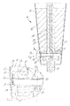
- Fig. 1 shows a schematic sectional view of an apparatus 10 for producing a cup of a conical sleeve 12 and a cup-shaped bottom 14.
- the device 10 may be part of a larger, not shown machine and for example, several of the devices 10 may be arranged on a star wheel.
- the sleeve 12 has been produced by winding and gluing or sealing in the region of a non-illustrated overlap of a flat segment.
- the pot-shaped bottom 14 has also been produced from a flat segment.
- the sleeve 12 is arranged on a likewise conical mandrel 16, which has a central guide bore, in which a punch 18 is guided for holding the bottom 14.
- the punch 18 has an actuating rod 20 and a stamp plate 21 with a stamp surface 22.
- the stamp surface 22 is located at an in Fig. 1 overhead floor surface 30 of the bottom 14 at.
- This overhead bottom surface 30 of the bottom 14 defines on the finished cup a lower boundary of the interior of the cup to be filled with liquid.
- From the bottom surface of the bottom 14 is a peripheral peripheral wall 24 extends, which extends at right angles to the bottom surface.
- the bottom 14 is replaced by a pot-like shape.
- the actuating rod 18 is provided with a through bore 26.
- a negative pressure is temporarily applied during the production process.
- the through-bore 26 opens into the punch surface 22, so that after applying a negative pressure to the bore 26, the bottom surface of the bottom 14 is pulled against the punch surface 22.
- the bottom 14 can thereby be safely inserted into the sleeve 12 without the risk that it falls off the stamp surface 22.
- an air outlet 28 which is adapted to blow warm air against the inside of the sleeve to facilitate deformation of the sleeve, and more specifically, turning the lower end of the sleeve 12 about the peripheral wall 24 of the bottom 14.
- radially warm air 29 flows out to heat the inside of the sleeve 12 in a region on which the peripheral wall 24 of the bottom 14 comes to rest below.
- a sealable coating on the inside of the sleeve 12 can be heated, in order then to allow the peripheral wall 24 to be sealed, and thus a fluid-tight connection of the circumferential wall 24 and sleeve 12.
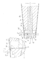
- the enlarged detail II in Fig. 2 lets first recognize the stamp surface 22, against which the bottom surface 30 of the bottom 14 is sucked.
- An outer side of the peripheral wall 24 of the bottom 14 is partially covered by an annular cover sleeve 32.
- the cover sleeve 32 abuts against a radially outer peripheral surface of the peripheral wall 24 of the bottom 14.
- the cover sleeve 32 prevents the radially outer surface of the peripheral wall 24 from coming into contact with an inner side 34 of the sleeve 12 before a predefined relative position of the bottom 14 and sleeve 12 is reached.
- the annular cover sleeve 32 is provided with an annular mounting plate 36 whose central bore is matched to the outer diameter of the actuating rod 18.
- the mounting plate 36 and the integrally connected with the mounting plate 36 annular cover sleeve 32 can thus be moved relative to the punch 18.
- an underside of the mounting plate 36 abuts on an upper side of the stamp plate 21. With its upper side, the mounting plate 36 bears against a surface of the mandrel 16.
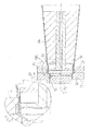
- Fig. 2 The punch 18 is moved together with the bottom 14 and the sleeve 32 down.
- FIG. 3 It is in Fig. 3 to recognize that starting from the state of Fig. 1 and the Fig. 2 the punch 18 has been moved down a path indicated by arrow 40 in FIG Fig. 3 is indicated. Because the top of the mounting plate 36 which is integrally connected to the annular cover sleeve 32 is now arranged at a distance from the mandrel 16. For this purpose, the actuating rod 18 has been displaced within the guide bore of the mandrel 16, as for example with reference to the upper end of the actuating rod 18, see Fig. 1 and Fig. 3 , is recognizable.
- the enlarged detail IV Fig. 3 is in Fig. 4 and reveals that the annular cover sleeve 32 now rests on the one hand on the inside of the sleeve 12 and on the other hand on the radially outer peripheral surface of the peripheral wall 24 of the bottom 14.
- the inner diameter of the cover sleeve 32 may be sized so that the bottom 14th is slightly compressed, so slightly rebounded after pulling out of the cover sleeve 32, so that then the peripheral wall 24 is substantially flat against the inside of the sleeve 12.
- the peripheral wall 24 of the bottom 14 does not abut against the inside of the sleeve 12, although the bottom 14 and the sleeve 12 are arranged in a relative position to each other, they also take each other on the finished cup.
- This punch 44 has a plurality of movable in the radial direction pressing jaws 46, which can be pressed by a centrally disposed actuator 48 radially outward.
- a centrally disposed actuator 48 On the outside of the sleeve 12 is located in the region of the peripheral wall 24 of the bottom 14 on an outer side of the sleeve 12, a retaining ring 50 at. This retaining ring 50 provides an abutment when the pressing jaws 48 are moved radially outward to urge the peripheral wall 24 against the inside of the sleeve 12.
- FIG. 6 shows the detail VI of Fig. 5 in an enlarged view.
- the peripheral wall 24 of the bottom 14 is now flat on the inside of the sleeve 12, since the annular cover sleeve 32 was pulled up between the peripheral wall 24 and the inside of the sleeve 12.
- the pressing jaws 46 and the retaining ring 50 now provide for a compression of the peripheral wall 24 with the inside of the sleeve 12 and thereby for a liquid-tight connection of the bottom 14 with the sleeve 12th
- the presentation of the Fig. 7 shows another, on the state of Fig. 5 or 6 following process step.
- the pressing jaws 46 and the retaining ring 50 have been removed.
- the in Fig. 7 is pushed from below onto the sleeve 12, a circumferential stacking shoulder 54 is inserted into the sleeve 12.
- This stack shoulder serves to reliably stack several cups in each other.
- a certain counterweight when sliding the press ring 52 provides the annular cover sleeve 32, which in the state of Fig. 7 is disposed radially inside the press ring 52.
- radially inwardly displaceable jaws 56 ensure that the lower edge 58 of the sleeve is turned radially inward.
- the jaws 56 are in FIGS. 7 and 8 shown in its radially inner end position.
- a the envelope of the lower edge 38 of the sleeve 12 causing radially inner edge of the jaw 56 is provided with a chamfer 57 which runs at a movement of the jaws 56 according to the arrows 55 on the lower edge 38 of the sleeve and the edge 38 by about 50 ° to 60 ° turns inside. Since all the jaws 56 have a chamfer 57, the edge 38 is turned inwards over its entire circumference.
- Another turn of the edge 38 then approximately 180 ° is effected by a punch 60, which starting from the state of Fig. 7 is moved upward according to the arrow 61.
- the turning over of the lower edge of the sleeve 12 is facilitated because, see Fig. 2 , the sleeve 12 has been previously heated in this envelope area.
- the presentation of the Fig. 8 shows the detail VIII of the Fig. 7 in an enlarged view.
- Fig. 10 shows the detail X the Fig. 9 in an enlarged view.
- FIG. 12 shows the enlarged detail XII Fig. 11 .
- Fig. 3 to 6 allows the annular cover sleeve to position the bottom and the sleeve 12 relative to each other so that they have already reached the provided on the finished cup relative position without touching the bottom 14 and the inside of the sleeve 12.
- touch see Fig. 4 , the radially outer surface of the peripheral wall 24 of the bottom 14 and the inside of the sleeve 12 not until the predefined relative position is reached.
- a possible high coefficient of friction between the material or the surface of the bottom 14 and the inside of the sleeve 12 does not hinder the manufacturing process of the cup.
Abstract
Die Erfindung betrifft ein Verfahren zum Herstellen eines Bechers aus einer konischen Hülse und einen topfförmigen Boden, wobei der Boden eine Bodenfläche und eine von der Bodenfläche ausgehende umlaufende Wandung aufweist und von einer größeren Öffnung der konischen Hülse her in Richtung auf die kleinere Öffnung der Hülse in die Hülse eingesetzt wird. Erfindungsgemäß sind die Schritte des wenigstens teilweisen Abdeckens einer radial außen liegenden Umfangsfläche der Wandung des topfförmigen Bodens mit einer ringförmigen Abdeckhülse, des Zustellens der Abdeckhülse zusammen mit dem Boden in Richtung auf die kleinere Öffnung der Hülse, bis eine vordefinierte Relativposition zwischen der Hülse und dem Boden erreicht ist, des Herausziehens der Abdeckhülse zwischen einer Innenseite der Hülse und der radial außen liegenden Umfangsfläche des Bodens, wobei der Boden in der vordefinierten Relativposition verbleibt, und des im Wesentlichen flüssigkeitsdichten Verbindens der radial außen liegenden Umfangsfläche des Bodens und der Innenseite der Hülse vorgesehen.The invention relates to a method for producing a cup from a conical sleeve and a cup-shaped bottom, wherein the bottom has a bottom surface and an outgoing from the bottom surface peripheral wall and from a larger opening of the conical sleeve forth in the direction of the smaller opening of the sleeve in the sleeve is inserted. According to the invention, the steps of at least partially covering a radially outer circumferential surface of the wall of the pot-shaped bottom with an annular cover sleeve, the delivery of the cover together with the bottom in the direction of the smaller opening of the sleeve, to a predefined relative position between the sleeve and the bottom is reached, the extraction of the cover sleeve between an inner side of the sleeve and the radially outer peripheral surface of the bottom, wherein the bottom remains in the predefined relative position, and the substantially liquid-tight connection of the radially outer peripheral surface of the bottom and the inside of the sleeve.
Description
Die Erfindung betrifft ein Verfahren zum Herstellen eines Bechers aus einer konischen Hülse und einem topfförmigen Boden, wobei der Boden eine Bodenfläche und eine von der Bodenfläche ausgehende umlaufende Wandung aufweist und von einer größeren Öffnung der konischen Hülse her in Richtung auf die kleinere Öffnung der Hülse in die Hülse eingesetzt wird. Die Erfindung betrifft auch eine Vorrichtung zum Herstellen eines Bechers aus einer konischen Hülse und einem topfförmigen Boden, wobei die Vorrichtung zum Einsetzen des Bodens von einer größeren Öffnung der konischen Hülse her in Richtung auf die kleinere Öffnung der Hülse in die Hülse ausgebildet ist.The invention relates to a method for producing a cup from a conical sleeve and a cup-shaped bottom, wherein the bottom has a bottom surface and an outgoing from the bottom surface peripheral wall and from a larger opening of the conical sleeve forth in the direction of the smaller opening of the sleeve in the sleeve is inserted. The invention also relates to a device for producing a cup from a conical sleeve and a cup-shaped bottom, wherein the device for inserting the bottom is formed by a larger opening of the conical sleeve in the direction of the smaller opening of the sleeve in the sleeve.
Bei bekannten Verfahren zum Herstellen eines Bechers und bei bekannten Vorrichtungen kann es beim Einsetzen des topfförmigen Bodens in die konische Hülse dann zu Problemen kommen, wenn der Boden während des Einsetzens an der Innenseite der Hülse anhaftet und dadurch eine korrekte Platzierung des Bodens in der Hülse behindert. Dies kann beispielsweise passieren, wenn der Boden und/oder die Hülse bereits mit Klebstoff beschichtet ist, wenn, beispielsweise auch nur aufgrund der Umgebungstemperaturen, das Material des Bodens und/oder der Hülse klebrig ist oder zumindest zwischen Boden und Hülse ein hoher Reibungskoeffizient vorliegt. Problematisch ist dabei, dass aufgrund der konischen Hülse und dem nachfolgenden flüssigkeitsdichten Verpressen von Boden und Hülse der Boden in eine Position innerhalb der Hülse gebracht werden muss, in der er zwangsläufig an einer Innenwand der Hülse anliegt. Anderenfalls ist ein Verpressen des Bodens mit der Hülse nicht möglich.Known methods of making a cup and prior art devices may encounter problems in inserting the cup-shaped bottom into the conical sleeve when the bottom adheres to the inside of the sleeve during insertion and thereby impedes proper placement of the bottom in the sleeve , This can happen, for example, if the bottom and / or the sleeve is already coated with adhesive, if, for example, only due to the ambient temperatures, the material of the bottom and / or the sleeve is sticky or at least between the bottom and sleeve is a high coefficient of friction. The problem here is that due to the conical sleeve and the subsequent liquid-tight pressing of the bottom and sleeve of the soil must be brought into a position within the sleeve in which he necessarily rests against an inner wall of the sleeve. Otherwise, a pressing of the soil with the sleeve is not possible.
Mit der Erfindung soll ein Verfahren und eine Vorrichtung zum Herstellen eines Bechers aus einer konischen Hülse und einem topfförmigen Boden verbessert werden.With the invention, a method and an apparatus for producing a cup of a conical sleeve and a cup-shaped bottom to be improved.
Erfindungsgemäß ist hierzu ein Verfahren mit den Merkmalen von Anspruch 1 vorgesehen. Zweckmäßige Weiterbildungen der Erfindung sind in den Unteransprüchen angegeben.According to the invention, a method with the features of claim 1 is provided for this purpose. Advantageous developments of the invention are specified in the subclaims.
Erfindungsgemäß ist das wenigstens teilweise Abdecken einer radial außen liegenden Umfangsfläche der Wandung des topfförmigen Bodens mit einer ringförmigen Abdeckhülse, das Anordnen der Abdeckhülse und des Bodens in einer vordefinierten Relativposition zwischen der Hülse und dem Boden, das Herausziehen der Abdeckhülse zwischen einer Innenseite der Hülse und der radial außen liegenden Umfangsfläche des Bodens, wobei der Boden in der vordefinierten Relativposition verbleibt, und das im Wesentlichen flüssigkeitsdichte Verbinden der radial außen liegenden Umfangsfläche des Bodens und der Innenseite der Hülse vorgesehen. Erfindungsgemäß wird somit eine ringförmige Abdeckhülse zwischen einer radial außen liegenden Umfangsfläche der Wandung des topfförmigen Bodens und der Innenseite der Hülse angeordnet. Damit kommt beim Zustellen des Bodens lediglich die Außenseite der Abdeckhülse in Kontakt mit der Innenseite der Hülse. Die Außenseite der Abdeckhülse kann in Bezug auf das Material bzw. die Oberfläche dabei so gewählt werden, dass die Abdeckhülse leichtgängig an der Innenseite der Hülse entlanggleiten kann. Erst dann, wenn der Boden eine vordefinierte Relativposition zur Hülse erreicht hat, wird die Abdeckhülse zwischen der Umfangswandung und der Innenseite der Hülse herausgezogen. Zu diesem Zeitpunkt befinden sich der Boden und die Hülse relativ zueinander aber bereits in Ruhe und an der vorgesehenen Relativposition. Ein eventuelles Anhaften von Boden und Hülse in dieser Position ist somit unschädlich und beim darauffolgenden Schritt des flüssigkeitsdichten Verbindens sogar erwünscht. Mit der Erfindung wird dadurch in überraschend einfacher Weise eine erhebliche Verbesserung eines Verfahrens zum Herstellen eines Bechers erzielt. Im Rahmen der Erfindung kann die Abdeckhülse dabei gemeinsam mit dem Boden in die Hülse hinein zugestellt werden oder die Abdeckhülse kann relativ zur Hülse stillstehen und der Boden wird in die Abdeckhülse hinein geschoben. Besondere Vorteile hat das erfindungsgemäße Verfahren dann, wenn aufgrund der Materialien von Boden und Hülse ein Anhaften des Bodens an der Hülse bei einer Relativbewegung zueinander zu befürchten ist. Die Erfindung ist damit in besonderer Weise für Materialien ausgebildet, deren Oberflächen zueinander einen hohen Reibungskoeffizient haben. Dies kann beispielsweise beschichtetes Papiermaterial oder beschichtete Pappe sein, beispielsweise aber auch papierähnlich zu verarbeitendes flächiges Kunststoffmaterial. Flächige Kunststoffmaterialien sind beispielsweise auch Kunststofflaminate. Die Erfindung ist dabei für papierähnlich zu verarbeitendes Kunststoffmaterial sehr gut geeignet, jedoch nicht speziell für papierähnlich zu verarbeitendes Kunststoffmaterial ausgebildet.According to the invention, the at least partially covering a radially outer peripheral surface of the wall of the cup-shaped bottom with an annular cover sleeve, arranging the cover and the bottom in a predefined relative position between the sleeve and the bottom, the extraction of the cover between an inner side of the sleeve and the radially outer peripheral surface of the bottom, wherein the bottom remains in the predefined relative position, and provided the substantially liquid-tight connection of the radially outer circumferential surface of the bottom and the inside of the sleeve. According to the invention thus an annular cover sleeve between a radially outer peripheral surface of the wall of the cup-shaped bottom and the inside of the sleeve is arranged. Thus, when delivering the soil, only the outside of the cover sleeve comes into contact with the inside of the sleeve. The outer side of the cover sleeve can be selected with respect to the material or the surface so that the cover sleeve can slide smoothly along the inside of the sleeve. Only when the bottom has reached a predefined relative position to the sleeve, the cover sleeve between the peripheral wall and the inside of the sleeve is pulled out. At this time, the bottom and the sleeve relative to each other but already at rest and at the intended relative position. A possible adhesion of soil and sleeve in this position is thus harmless and even desirable in the subsequent step of liquid-tight bonding. With the invention, a considerable improvement of a method for producing a cup is achieved in a surprisingly simple manner. In the context of the invention, the covering sleeve can be delivered together with the ground into the sleeve or the covering sleeve can rest relative to the sleeve and the bottom is pushed into the covering sleeve. Particular advantages of the method according to the invention then, if due to the materials of the bottom and sleeve adhesion of the soil to the sleeve in a relative movement is to be feared each other. The invention is thus designed in a special way for materials whose surfaces have a high coefficient of friction to each other. This can be, for example, coated paper material or coated cardboard, for example, but also paper-like to be processed flat plastic material. Flat plastic materials are, for example, also plastic laminates. The invention is very well suited for paper-like plastic material to be processed, but not specifically designed for paper-like plastic material to be processed.
In Weiterbildung der Erfindung entspricht die vordefinierte Relativposition wenigstens in Längsrichtung der Hülse gesehen der Relativposition von Boden und Hülse am fertiggestellten Becher.In a further development of the invention, the predefined relative position, as seen in the longitudinal direction of the sleeve, corresponds to the relative position of the base and sleeve on the finished cup.
Auf diese Weise müssen Boden und Hülse relativ zueinander nicht mehr bewegt werden, nachdem die Abdeckhülse zwischen der Umfangswand des Bodens und der Innenseite der Hülse herausgezogen wurde. Geringfügige Verschiebungen während des flüssigkeitsdichten Verbindens von Boden und Hülse sind hiervon ausgenommen.In this way, bottom and sleeve relative to each other must not be moved after the cover sleeve between the peripheral wall of the bottom and the inside of the sleeve has been pulled out. Minor displacements during liquid-tight bonding of the bottom and sleeve are excluded.
In Weiterbildung der Erfindung liegt in der vordefinierten Relativposition eine außen liegende Umfangsfläche der Abdeckhülse an der Innenseite der Hülse wenigstens abschnittsweise an oder ist unmittelbar angrenzend an die Innenseite der Hülse angeordnet.In a further development of the invention, in the predefined relative position, an outer peripheral surface of the cover sleeve is located at least in sections on the inner side of the sleeve or is arranged directly adjacent to the inner side of the sleeve.
Auf diese Weise können die Umfangswand des Bodens und die Innenseite der Hülse sehr nahe zueinander gebracht werden, ohne unmittelbar in Kontakt zu stehen. Beispielsweise kann der Boden unter leichter Vorspannung in der Abdeckhülse angeordnet werden, so dass sich die Umfangswand nach Herausziehen der Abdeckhülse geringfügig aufweitet und dann die Umfangswand des Bodens flächig an der Innenseite der Hülse anliegt.In this way, the peripheral wall of the bottom and the inside of the sleeve can be brought very close to each other without being in direct contact. For example, the bottom can be arranged under slight bias in the cover sleeve, so that the peripheral wall slightly widened after pulling out of the cover and then the peripheral wall of the bottom rests flat against the inside of the sleeve.
In Weiterbildung der Erfindung ist vorgesehen, die Abdeckhülse zusammen mit dem Boden in Richtung auf die kleinere Öffnung der Hülse zuzustellen, bis die vordefinierte Relativposition erreicht ist.In a further development of the invention, it is provided to deliver the cover sleeve together with the base in the direction of the smaller opening of the sleeve until the predefined relative position is reached.
Erfindungsgemäß ist auch eine Vorrichtung zum Herstellen eines Bechers aus einer konischen Hülse und einem topfförmigen Boden mit den Merkmalen von Anspruch 5 vorgesehen. Zweckmäßige Weiterbildungen der Erfindung sind in den Unteransprüchen angegeben.According to the invention, an apparatus for producing a cup from a conical sleeve and a cup-shaped bottom with the features of claim 5 is provided. Advantageous developments of the invention are specified in the subclaims.
Erfindungsgemäß ist die Vorrichtung zum Herstellen eines Bechers aus einer konischen Hülse und einem topfförmigen Boden zum Einsetzen des Bodens von einer größeren Öffnung der konischen Hülse her in Richtung auf die kleinere Öffnung der Hülse in die Hülse ausgebildet. Die Vorrichtung weist eine ringförmige Abdeckhülse auf, deren Innenumfang so groß ist, dass eine Umfangswandung des topfförmigen Bodens an dem Innenumfang anliegt. Weiter weist die Vorrichtung eine Einrichtung zum Bewegen der Abdeckhülse in und entgegen einer Längsrichtung der Hülse und eine Einrichtung zum Festhalten des Bodens in einer vordefinierten Relativposition zur Hülse bei gleichzeitigem Herausziehen der Abdeckhülse zwischen der Innenseite der Hülse und der Umfangswandung des Bodens auf. Mit der erfindungsgemäßen Vorrichtung wird das Herstellen eines Bechers aus einer konischen Hülse und einem topfförmigen Boden erheblich erleichtert, vor allem dann, wenn die Materialien bzw. die Oberflächen von Boden und Hülse einen hohen Reibungskoeffizienten zueinander aufweisen und daher das Anhaften des Bodens an der Hülse bei einer Relativbewegung zu befürchten ist. Dies kann beispielsweise bei flüssigkeitsdicht beschichtetem Papiermaterial oder auch bei papierähnlich zu verarbeitenden Kunststoffmaterialien auftreten.According to the invention, the device for producing a cup from a conical sleeve and a cup-shaped bottom for inserting the bottom of a larger opening of the conical sleeve forth in the direction of the smaller opening of the sleeve is formed in the sleeve. The device has an annular cover sleeve whose inner circumference is so large that a peripheral wall of the cup-shaped bottom bears against the inner circumference. Further, the device comprises means for moving the cover sleeve in and against a longitudinal direction of the sleeve and means for retaining the bottom in a predefined relative position to the sleeve while pulling the cover sleeve between the inside of the sleeve and the peripheral wall of the bottom. With the device according to the invention the production of a cup of a conical sleeve and a cup-shaped bottom is greatly facilitated, especially if the materials or the surfaces of the bottom and sleeve have a high coefficient of friction to each other and therefore the adhesion of the bottom of the sleeve at a relative movement is to be feared. This can occur, for example, in liquid-tight coated paper material or in paper-like plastic materials to be processed.
In Weiterbildung der Erfindung ist ein Stempel zum Halten des Bodens vorgesehen, wobei der Stempel eine Betätigungsstange und eine am Boden anliegende Stempelfläche aufweist, wobei die Abdeckhülse verschiebbar auf der Betätigungsstange des Stempels angeordnet ist.In a further development of the invention, a stamp for holding the bottom is provided, wherein the punch has an actuating rod and a voltage applied to the ground stamp surface, wherein the cover sleeve is slidably mounted on the actuating rod of the punch.
Auf diese Weise kann die Abdeckhülse beispielsweise exakt konzentrisch zur Betätigungsstange angeordnet werden und auch während des Herausziehens der Abdeckhülse zwischen einer Innenseite der Hülse und der radial außen liegenden Umfangsfläche des Bodens ist die Abdeckhülse sicher geführt. Die erfindungsgemäße Vorrichtung kann dadurch hohe Geschwindigkeiten und damit geringe Taktzeiten bei der Herstellung von Bechern erzielen.In this way, the cover can be arranged for example exactly concentric with the actuating rod and also during withdrawal of the cover between an inner side of the sleeve and the radially outer circumferential surface of the bottom is the cover safely guided. The device according to the invention can thereby achieve high speeds and thus low cycle times in the production of cups.
Weitere Merkmale und Vorteile der Erfindung ergeben sich aus den Ansprüchen und der nachfolgenden Beschreibung bevorzugter Ausführungsformen der Erfindung im Zusammenhang mit den Zeichnungen. Einzelmerkmale der unterschiedlichen Ausführungsformen können dabei in beliebiger Weise miteinander kombiniert werden, ohne den Rahmen der Erfindung zu überschreiten. In den Zeichnungen zeigen:
- Fig. 1
- eine schematische Schnittansicht einer Vorrichtung zum Herstellen eines Bechers in einem ersten Zustand,
- Fig. 2
- die vergrößerte Einzelheit I aus
Fig. 1 , - Fig. 3
- eine schematische Schnittansicht der Vorrichtung der
Fig. 1 in einem zweiten Zustand, - Fig. 4
- die Einzelheit IV der
Fig. 3 in vergrößerter Darstellung, - Fig. 5
- eine schematische Schnittansicht der Vorrichtung der
Fig. 1 in einem dritten Zustand, - Fig. 6
- die Einzelheit VI der
Fig. 5 in vergrößerter Darstellung, - Fig. 7
- eine schematische Schnittansicht der Vorrichtung der
Fig. 1 in einem vierten Zustand, - Fig. 8
- die vergrößerte Einzelheit VIII aus
Fig. 7 , - Fig. 9
- die Vorrichtung der
Fig. 1 in einem fünften Zustand, - Fig. 10
- die Einzelheit X der
Fig. 9 in vergrößerter Darstellung, - Fig. 11
- die Vorrichtung der
Fig. 1 in einem sechsten Zustand und - Fig. 12
- die Einzelheit XII aus
Fig. 11 in vergrößerter Darstellung.
- Fig. 1
- a schematic sectional view of an apparatus for producing a cup in a first state,
- Fig. 2
- the enlarged detail I off
Fig. 1 . - Fig. 3
- a schematic sectional view of the device of
Fig. 1 in a second state, - Fig. 4
- the detail IV of
Fig. 3 in an enlarged view, - Fig. 5
- a schematic sectional view of the device of
Fig. 1 in a third state, - Fig. 6
- the detail VI of
Fig. 5 in an enlarged view, - Fig. 7
- a schematic sectional view of the device of
Fig. 1 in a fourth state, - Fig. 8
- the enlarged detail VIII
Fig. 7 . - Fig. 9
- the device of
Fig. 1 in a fifth state, - Fig. 10
- the detail X the
Fig. 9 in an enlarged view, - Fig. 11
- the device of
Fig. 1 in a sixth state and - Fig. 12
- the detail XII
Fig. 11 in an enlarged view.
Die Hülse 12 ist durch Wickeln und Verkleben bzw. Versiegeln im Bereich einer nicht dargestellten Überlappung aus einem flächigen Segment hergestellt worden. Der topfförmige Boden 14 ist ebenfalls aus einem flächigen Segment hergestellt worden. Die Hülse 12 ist auf einem ebenfalls konischen Dorn 16 angeordnet, der eine zentrale Führungsbohrung aufweist, in der ein Stempel 18 zum Halten des Bodens 14 geführt ist. Der Stempel 18 weist eine Betätigungsstange 20 und eine Stempelplatte 21 mit einer Stempelfläche 22 auf. Die Stempelfläche 22 liegt an einer in
Die Betätigungsstange 18 ist mit einer durchgehenden Bohrung 26 versehen. An die Bohrung 26 wird während des Produktionsprozesses zeitweise ein Unterdruck angelegt. Die Durchgangsbohrung 26 mündet in der Stempelfläche 22, so dass nach Anlegen eines Unterdrucks an die Bohrung 26 die Bodenfläche des Bodens 14 gegen die Stempelfläche 22 gezogen wird. Der Boden 14 kann dadurch sicher und ohne die Gefahr, dass er von der Stempelfläche 22 abfällt, in die Hülse 12 eingeschoben werden.The actuating
In der Darstellung der
Unterhalb des Bodens 14 ist ein Luftauslass 28 angeordnet, der dazu vorgesehen ist, warme Luft gegen die Innenseite der Hülse zu blasen, um die Verformung der Hülse und speziell das Umschlagen des unteren Endes der Hülse 12 um die Umfangswand 24 des Bodens 14 zu erleichtern. Aus dem Blasteil 28 strömt radial warme Luft 29 aus, um die Innenseite der Hülse 12 in einem Bereich zu erwärmen, auf dem nachfolgend die Umfangswandung 24 des Bodens 14 zu liegen kommt. Beispielsweise kann eine siegelfähige Beschichtung der Innenseite der Hülse 12 erwärmt werden, um dann ein Ansiegeln der Umfangswand 24 und damit eine flüssigkeitsdichte Verbindung von Umfangswand 24 und Hülse 12 zu ermöglichen.Below the bottom 14 there is disposed an
Die vergrößerte Einzelheit II in
Die ringförmige Abdeckhülse 32 ist mit einer kreisringförmigen Befestigungsplatte 36 versehen, deren mittige Bohrung auf den Außendurchmesser der Betätigungsstange 18 abgestimmt ist. Die Befestigungsplatte 36 und die einstückig mit der Befestigungsplatte 36 verbundene ringförmige Abdeckhülse 32 können damit relativ zum Stempel 18 verschoben werden. In dem Zustand der
Ausgehend von dem Zustand der
Dieser Zustand ist dann in
Es ist in
Die vergrößerte Einzelheit IV aus
Ausgehend vom Zustand der
Wesentlich ist, dass zum Verpressen der Umfangswand 24 und der Innenseite der Hülse 12, die ausgehend von dem Zustand der
Die Darstellung der
Die Darstellung der
Die Darstellung der
Ausgehend vom Zustand der
Wie in
Die Darstellung der
Wie vor allem anhand der
Claims (6)
Applications Claiming Priority (1)
| Application Number | Priority Date | Filing Date | Title |
|---|---|---|---|
| DE102014210961.2A DE102014210961A1 (en) | 2014-06-06 | 2014-06-06 | Method and apparatus for making a cup |
Publications (2)
| Publication Number | Publication Date |
|---|---|
| EP2955011A1 true EP2955011A1 (en) | 2015-12-16 |
| EP2955011B1 EP2955011B1 (en) | 2017-09-13 |
Family
ID=53365744
Family Applications (1)
| Application Number | Title | Priority Date | Filing Date |
|---|---|---|---|
| EP15168688.8A Not-in-force EP2955011B1 (en) | 2014-06-06 | 2015-05-21 | Method and device for manufacturing a container |
Country Status (5)
| Country | Link |
|---|---|
| US (1) | US10112359B2 (en) |
| EP (1) | EP2955011B1 (en) |
| CN (1) | CN105269871B (en) |
| BR (1) | BR102015013147A2 (en) |
| DE (1) | DE102014210961A1 (en) |
Families Citing this family (1)
| Publication number | Priority date | Publication date | Assignee | Title |
|---|---|---|---|---|
| CN109940923A (en) * | 2019-03-22 | 2019-06-28 | 李晓鹏 | A kind of processing technology of container of wipes |
Citations (3)
| Publication number | Priority date | Publication date | Assignee | Title |
|---|---|---|---|---|
| US2216331A (en) * | 1938-10-28 | 1940-10-01 | Us Envelope Co | Method of and apparatus for producing paper cups |
| US3063347A (en) * | 1960-03-31 | 1962-11-13 | Hudson Pulp & Paper Corp | Cup making machine |
| US4100842A (en) * | 1977-05-18 | 1978-07-18 | Phillips Petroleum Company | Apparatus for forming a container |
Family Cites Families (11)
| Publication number | Priority date | Publication date | Assignee | Title |
|---|---|---|---|---|
| US2169345A (en) * | 1937-05-24 | 1939-08-15 | Jagenberg Werke Ag | Method and machine for producing paper containers |
| US3157339A (en) * | 1961-07-18 | 1964-11-17 | Continental Can Co | Paper cup with caulked bottom and method of making |
| US3342113A (en) * | 1965-03-26 | 1967-09-19 | Donald W Baumgartner | Method of making two-piece paper cups |
| US3602690A (en) * | 1968-10-03 | 1971-08-31 | Maryland Cup Corp | A quick acting air heater |
| US3673033A (en) * | 1970-02-02 | 1972-06-27 | Sweethart Plastics Inc | Method for making disposable plastic bucket |
| JPS58163641A (en) * | 1982-03-24 | 1983-09-28 | 大日本印刷株式会社 | Method and device for molding vessel bottom |
| US4409045A (en) * | 1982-07-20 | 1983-10-11 | Maryland Cup Corporation | Method and apparatus for sealing the sidewall and bottom seam portions of two-piece containers during manufacture thereof |
| US5507640A (en) | 1992-12-11 | 1996-04-16 | Amoco Corporation | Apparatus and method useful in manufacture of two piece cups |
| JP4019728B2 (en) * | 2002-02-13 | 2007-12-12 | 凸版印刷株式会社 | Method for molding cup-shaped paper container bottom and cup-shaped paper container produced by the molding method |
| EP1785265A1 (en) | 2005-11-14 | 2007-05-16 | SEDA S.p.A. | Device for producing a stacking projection on a container wall and container with same |
| TW201345804A (en) * | 2012-02-01 | 2013-11-16 | Toppan Printing Co Ltd | Funnel part and method of manufacturing packaging container utilizing funnel part |
-
2014
- 2014-06-06 DE DE102014210961.2A patent/DE102014210961A1/en not_active Withdrawn
-
2015
- 2015-05-21 EP EP15168688.8A patent/EP2955011B1/en not_active Not-in-force
- 2015-06-05 BR BR102015013147A patent/BR102015013147A2/en active Search and Examination
- 2015-06-05 US US14/732,100 patent/US10112359B2/en not_active Expired - Fee Related
- 2015-06-05 CN CN201510302206.4A patent/CN105269871B/en not_active Expired - Fee Related
Patent Citations (3)
| Publication number | Priority date | Publication date | Assignee | Title |
|---|---|---|---|---|
| US2216331A (en) * | 1938-10-28 | 1940-10-01 | Us Envelope Co | Method of and apparatus for producing paper cups |
| US3063347A (en) * | 1960-03-31 | 1962-11-13 | Hudson Pulp & Paper Corp | Cup making machine |
| US4100842A (en) * | 1977-05-18 | 1978-07-18 | Phillips Petroleum Company | Apparatus for forming a container |
Also Published As
| Publication number | Publication date |
|---|---|
| CN105269871A (en) | 2016-01-27 |
| EP2955011B1 (en) | 2017-09-13 |
| US10112359B2 (en) | 2018-10-30 |
| DE102014210961A1 (en) | 2015-12-17 |
| US20150352800A1 (en) | 2015-12-10 |
| CN105269871B (en) | 2019-11-15 |
| BR102015013147A2 (en) | 2016-01-05 |
Similar Documents
| Publication | Publication Date | Title |
|---|---|---|
| DE102008064505B4 (en) | Method for producing glued sleeves | |
| DE1704340C3 (en) | Method and device for producing a container made of thermoplastic material | |
| DE1479343A1 (en) | Method and device for deep drawing | |
| DE102008005403A1 (en) | Mug made of a paper material | |
| DE1276898B (en) | Method and device for producing a cup or the like from plastic film | |
| EP2426080B1 (en) | Method for manufacturing a funnel, funnel and container with funnel | |
| DE102008031812A1 (en) | Device for pressing two or multiple layers of cup or made of plastic and paper material, particularly from inner cover, has outer cover of insulating cup and two radially expanding die stocks | |
| EP2952340B1 (en) | Method for producing a container | |
| EP3147115A1 (en) | Machine and method for the production of a cup | |
| DE102009031691A1 (en) | Apparatus and method for making sleeves | |
| EP3140200A1 (en) | Method and device for producing molded parts from a continuous fiber-material sheet | |
| EP0007487A1 (en) | Sealed can and preformed closure element therefor, as well as method and apparatuses for manufacturing them | |
| DE102009055986A1 (en) | Apparatus for applying adhesive and machine and method for producing paper cups | |
| EP3137382B1 (en) | Method and device for thermally activating packaging sheaths | |
| EP2955011B1 (en) | Method and device for manufacturing a container | |
| DE19516100A1 (en) | Process for producing and / or filling a two-chamber pressure pack | |
| EP2996855B1 (en) | Method and device for pressing a sealing compound on the inside of a lid for containers | |
| EP3724082B1 (en) | Package and method for producing said package | |
| DE102013103743B4 (en) | Thermoforming packaging and process for its production | |
| DE2704117A1 (en) | METHOD OF MANUFACTURING A SUBSTANTLY CONICAL CAN FROM THIN SHEET METAL, AND TOOLS FOR CARRYING OUT THE PROCESS | |
| DE1906796A1 (en) | Device for connecting inserts with sleeves using press jaws | |
| EP2886361B1 (en) | Method and device for producing desk calendars | |
| EP1568451A1 (en) | Method and apparatus for punching a filtering medium | |
| DE102017119032A1 (en) | Method and apparatus for applying a sealant to the floor and the inside of an annular wall of a lid for containers | |
| DE102018101864A1 (en) | Packaging and process for its production |
Legal Events
| Date | Code | Title | Description |
|---|---|---|---|
| PUAI | Public reference made under article 153(3) epc to a published international application that has entered the european phase |
Free format text: ORIGINAL CODE: 0009012 |
|
| AK | Designated contracting states |
Kind code of ref document: A1 Designated state(s): AL AT BE BG CH CY CZ DE DK EE ES FI FR GB GR HR HU IE IS IT LI LT LU LV MC MK MT NL NO PL PT RO RS SE SI SK SM TR |
|
| AX | Request for extension of the european patent |
Extension state: BA ME |
|
| 17P | Request for examination filed |
Effective date: 20160614 |
|
| RBV | Designated contracting states (corrected) |
Designated state(s): AL AT BE BG CH CY CZ DE DK EE ES FI FR GB GR HR HU IE IS IT LI LT LU LV MC MK MT NL NO PL PT RO RS SE SI SK SM TR |
|
| REG | Reference to a national code |
Ref country code: DE Ref legal event code: R079 Ref document number: 502015001837 Country of ref document: DE Free format text: PREVIOUS MAIN CLASS: B31B0001000000 Ipc: B31B0050000000 |
|
| GRAP | Despatch of communication of intention to grant a patent |
Free format text: ORIGINAL CODE: EPIDOSNIGR1 |
|
| RIC1 | Information provided on ipc code assigned before grant |
Ipc: B31B 50/00 20170101AFI20170331BHEP |
|
| INTG | Intention to grant announced |
Effective date: 20170428 |
|
| GRAS | Grant fee paid |
Free format text: ORIGINAL CODE: EPIDOSNIGR3 |
|
| GRAJ | Information related to disapproval of communication of intention to grant by the applicant or resumption of examination proceedings by the epo deleted |
Free format text: ORIGINAL CODE: EPIDOSDIGR1 |
|
| GRAL | Information related to payment of fee for publishing/printing deleted |
Free format text: ORIGINAL CODE: EPIDOSDIGR3 |
|
| GRAR | Information related to intention to grant a patent recorded |
Free format text: ORIGINAL CODE: EPIDOSNIGR71 |
|
| GRAA | (expected) grant |
Free format text: ORIGINAL CODE: 0009210 |
|
| INTC | Intention to grant announced (deleted) | ||
| AK | Designated contracting states |
Kind code of ref document: B1 Designated state(s): AL AT BE BG CH CY CZ DE DK EE ES FI FR GB GR HR HU IE IS IT LI LT LU LV MC MK MT NL NO PL PT RO RS SE SI SK SM TR |
|
| INTG | Intention to grant announced |
Effective date: 20170808 |
|
| REG | Reference to a national code |
Ref country code: GB Ref legal event code: FG4D Free format text: NOT ENGLISH |
|
| REG | Reference to a national code |
Ref country code: CH Ref legal event code: EP |
|
| REG | Reference to a national code |
Ref country code: IE Ref legal event code: FG4D Free format text: LANGUAGE OF EP DOCUMENT: GERMAN |
|
| REG | Reference to a national code |
Ref country code: AT Ref legal event code: REF Ref document number: 927719 Country of ref document: AT Kind code of ref document: T Effective date: 20171015 |
|
| REG | Reference to a national code |
Ref country code: DE Ref legal event code: R096 Ref document number: 502015001837 Country of ref document: DE |
|
| REG | Reference to a national code |
Ref country code: NL Ref legal event code: MP Effective date: 20170913 |
|
| REG | Reference to a national code |
Ref country code: LT Ref legal event code: MG4D |
|
| PG25 | Lapsed in a contracting state [announced via postgrant information from national office to epo] |
Ref country code: FI Free format text: LAPSE BECAUSE OF FAILURE TO SUBMIT A TRANSLATION OF THE DESCRIPTION OR TO PAY THE FEE WITHIN THE PRESCRIBED TIME-LIMIT Effective date: 20170913 Ref country code: LT Free format text: LAPSE BECAUSE OF FAILURE TO SUBMIT A TRANSLATION OF THE DESCRIPTION OR TO PAY THE FEE WITHIN THE PRESCRIBED TIME-LIMIT Effective date: 20170913 Ref country code: HR Free format text: LAPSE BECAUSE OF FAILURE TO SUBMIT A TRANSLATION OF THE DESCRIPTION OR TO PAY THE FEE WITHIN THE PRESCRIBED TIME-LIMIT Effective date: 20170913 Ref country code: SE Free format text: LAPSE BECAUSE OF FAILURE TO SUBMIT A TRANSLATION OF THE DESCRIPTION OR TO PAY THE FEE WITHIN THE PRESCRIBED TIME-LIMIT Effective date: 20170913 Ref country code: NO Free format text: LAPSE BECAUSE OF FAILURE TO SUBMIT A TRANSLATION OF THE DESCRIPTION OR TO PAY THE FEE WITHIN THE PRESCRIBED TIME-LIMIT Effective date: 20171213 |
|
| PG25 | Lapsed in a contracting state [announced via postgrant information from national office to epo] |
Ref country code: RS Free format text: LAPSE BECAUSE OF FAILURE TO SUBMIT A TRANSLATION OF THE DESCRIPTION OR TO PAY THE FEE WITHIN THE PRESCRIBED TIME-LIMIT Effective date: 20170913 Ref country code: GR Free format text: LAPSE BECAUSE OF FAILURE TO SUBMIT A TRANSLATION OF THE DESCRIPTION OR TO PAY THE FEE WITHIN THE PRESCRIBED TIME-LIMIT Effective date: 20171214 Ref country code: BG Free format text: LAPSE BECAUSE OF FAILURE TO SUBMIT A TRANSLATION OF THE DESCRIPTION OR TO PAY THE FEE WITHIN THE PRESCRIBED TIME-LIMIT Effective date: 20171213 Ref country code: LV Free format text: LAPSE BECAUSE OF FAILURE TO SUBMIT A TRANSLATION OF THE DESCRIPTION OR TO PAY THE FEE WITHIN THE PRESCRIBED TIME-LIMIT Effective date: 20170913 Ref country code: ES Free format text: LAPSE BECAUSE OF FAILURE TO SUBMIT A TRANSLATION OF THE DESCRIPTION OR TO PAY THE FEE WITHIN THE PRESCRIBED TIME-LIMIT Effective date: 20170913 |
|
| PG25 | Lapsed in a contracting state [announced via postgrant information from national office to epo] |
Ref country code: NL Free format text: LAPSE BECAUSE OF FAILURE TO SUBMIT A TRANSLATION OF THE DESCRIPTION OR TO PAY THE FEE WITHIN THE PRESCRIBED TIME-LIMIT Effective date: 20170913 |
|
| PG25 | Lapsed in a contracting state [announced via postgrant information from national office to epo] |
Ref country code: CZ Free format text: LAPSE BECAUSE OF FAILURE TO SUBMIT A TRANSLATION OF THE DESCRIPTION OR TO PAY THE FEE WITHIN THE PRESCRIBED TIME-LIMIT Effective date: 20170913 Ref country code: RO Free format text: LAPSE BECAUSE OF FAILURE TO SUBMIT A TRANSLATION OF THE DESCRIPTION OR TO PAY THE FEE WITHIN THE PRESCRIBED TIME-LIMIT Effective date: 20170913 Ref country code: PL Free format text: LAPSE BECAUSE OF FAILURE TO SUBMIT A TRANSLATION OF THE DESCRIPTION OR TO PAY THE FEE WITHIN THE PRESCRIBED TIME-LIMIT Effective date: 20170913 |
|
| REG | Reference to a national code |
Ref country code: FR Ref legal event code: PLFP Year of fee payment: 4 |
|
| PG25 | Lapsed in a contracting state [announced via postgrant information from national office to epo] |
Ref country code: IT Free format text: LAPSE BECAUSE OF FAILURE TO SUBMIT A TRANSLATION OF THE DESCRIPTION OR TO PAY THE FEE WITHIN THE PRESCRIBED TIME-LIMIT Effective date: 20170913 Ref country code: SM Free format text: LAPSE BECAUSE OF FAILURE TO SUBMIT A TRANSLATION OF THE DESCRIPTION OR TO PAY THE FEE WITHIN THE PRESCRIBED TIME-LIMIT Effective date: 20170913 Ref country code: IS Free format text: LAPSE BECAUSE OF FAILURE TO SUBMIT A TRANSLATION OF THE DESCRIPTION OR TO PAY THE FEE WITHIN THE PRESCRIBED TIME-LIMIT Effective date: 20180113 Ref country code: SK Free format text: LAPSE BECAUSE OF FAILURE TO SUBMIT A TRANSLATION OF THE DESCRIPTION OR TO PAY THE FEE WITHIN THE PRESCRIBED TIME-LIMIT Effective date: 20170913 Ref country code: EE Free format text: LAPSE BECAUSE OF FAILURE TO SUBMIT A TRANSLATION OF THE DESCRIPTION OR TO PAY THE FEE WITHIN THE PRESCRIBED TIME-LIMIT Effective date: 20170913 |
|
| REG | Reference to a national code |
Ref country code: DE Ref legal event code: R097 Ref document number: 502015001837 Country of ref document: DE |
|
| PLBE | No opposition filed within time limit |
Free format text: ORIGINAL CODE: 0009261 |
|
| STAA | Information on the status of an ep patent application or granted ep patent |
Free format text: STATUS: NO OPPOSITION FILED WITHIN TIME LIMIT |
|
| PG25 | Lapsed in a contracting state [announced via postgrant information from national office to epo] |
Ref country code: DK Free format text: LAPSE BECAUSE OF FAILURE TO SUBMIT A TRANSLATION OF THE DESCRIPTION OR TO PAY THE FEE WITHIN THE PRESCRIBED TIME-LIMIT Effective date: 20170913 |
|
| 26N | No opposition filed |
Effective date: 20180614 |
|
| PG25 | Lapsed in a contracting state [announced via postgrant information from national office to epo] |
Ref country code: MT Free format text: LAPSE BECAUSE OF FAILURE TO SUBMIT A TRANSLATION OF THE DESCRIPTION OR TO PAY THE FEE WITHIN THE PRESCRIBED TIME-LIMIT Effective date: 20170913 |
|
| PG25 | Lapsed in a contracting state [announced via postgrant information from national office to epo] |
Ref country code: SI Free format text: LAPSE BECAUSE OF FAILURE TO SUBMIT A TRANSLATION OF THE DESCRIPTION OR TO PAY THE FEE WITHIN THE PRESCRIBED TIME-LIMIT Effective date: 20170913 |
|
| REG | Reference to a national code |
Ref country code: CH Ref legal event code: PL |
|
| REG | Reference to a national code |
Ref country code: BE Ref legal event code: MM Effective date: 20180531 |
|
| PG25 | Lapsed in a contracting state [announced via postgrant information from national office to epo] |
Ref country code: MC Free format text: LAPSE BECAUSE OF FAILURE TO SUBMIT A TRANSLATION OF THE DESCRIPTION OR TO PAY THE FEE WITHIN THE PRESCRIBED TIME-LIMIT Effective date: 20170913 |
|
| REG | Reference to a national code |
Ref country code: IE Ref legal event code: MM4A |
|
| PG25 | Lapsed in a contracting state [announced via postgrant information from national office to epo] |
Ref country code: LI Free format text: LAPSE BECAUSE OF NON-PAYMENT OF DUE FEES Effective date: 20180531 Ref country code: CH Free format text: LAPSE BECAUSE OF NON-PAYMENT OF DUE FEES Effective date: 20180531 |
|
| PG25 | Lapsed in a contracting state [announced via postgrant information from national office to epo] |
Ref country code: LU Free format text: LAPSE BECAUSE OF NON-PAYMENT OF DUE FEES Effective date: 20180521 |
|
| PG25 | Lapsed in a contracting state [announced via postgrant information from national office to epo] |
Ref country code: IE Free format text: LAPSE BECAUSE OF NON-PAYMENT OF DUE FEES Effective date: 20180521 |
|
| PG25 | Lapsed in a contracting state [announced via postgrant information from national office to epo] |
Ref country code: BE Free format text: LAPSE BECAUSE OF NON-PAYMENT OF DUE FEES Effective date: 20180531 |
|
| GBPC | Gb: european patent ceased through non-payment of renewal fee |
Effective date: 20190521 |
|
| PG25 | Lapsed in a contracting state [announced via postgrant information from national office to epo] |
Ref country code: TR Free format text: LAPSE BECAUSE OF FAILURE TO SUBMIT A TRANSLATION OF THE DESCRIPTION OR TO PAY THE FEE WITHIN THE PRESCRIBED TIME-LIMIT Effective date: 20170913 |
|
| PG25 | Lapsed in a contracting state [announced via postgrant information from national office to epo] |
Ref country code: GB Free format text: LAPSE BECAUSE OF NON-PAYMENT OF DUE FEES Effective date: 20190521 |
|
| PG25 | Lapsed in a contracting state [announced via postgrant information from national office to epo] |
Ref country code: PT Free format text: LAPSE BECAUSE OF FAILURE TO SUBMIT A TRANSLATION OF THE DESCRIPTION OR TO PAY THE FEE WITHIN THE PRESCRIBED TIME-LIMIT Effective date: 20170913 |
|
| PG25 | Lapsed in a contracting state [announced via postgrant information from national office to epo] |
Ref country code: CY Free format text: LAPSE BECAUSE OF FAILURE TO SUBMIT A TRANSLATION OF THE DESCRIPTION OR TO PAY THE FEE WITHIN THE PRESCRIBED TIME-LIMIT Effective date: 20170913 Ref country code: MK Free format text: LAPSE BECAUSE OF NON-PAYMENT OF DUE FEES Effective date: 20170913 Ref country code: HU Free format text: LAPSE BECAUSE OF FAILURE TO SUBMIT A TRANSLATION OF THE DESCRIPTION OR TO PAY THE FEE WITHIN THE PRESCRIBED TIME-LIMIT; INVALID AB INITIO Effective date: 20150521 |
|
| PG25 | Lapsed in a contracting state [announced via postgrant information from national office to epo] |
Ref country code: AL Free format text: LAPSE BECAUSE OF FAILURE TO SUBMIT A TRANSLATION OF THE DESCRIPTION OR TO PAY THE FEE WITHIN THE PRESCRIBED TIME-LIMIT Effective date: 20170913 |
|
| PGFP | Annual fee paid to national office [announced via postgrant information from national office to epo] |
Ref country code: DE Payment date: 20200520 Year of fee payment: 6 Ref country code: FR Payment date: 20200519 Year of fee payment: 6 |
|
| PGFP | Annual fee paid to national office [announced via postgrant information from national office to epo] |
Ref country code: AT Payment date: 20200515 Year of fee payment: 6 |
|
| REG | Reference to a national code |
Ref country code: DE Ref legal event code: R119 Ref document number: 502015001837 Country of ref document: DE |
|
| REG | Reference to a national code |
Ref country code: AT Ref legal event code: MM01 Ref document number: 927719 Country of ref document: AT Kind code of ref document: T Effective date: 20210521 |
|
| PG25 | Lapsed in a contracting state [announced via postgrant information from national office to epo] |
Ref country code: AT Free format text: LAPSE BECAUSE OF NON-PAYMENT OF DUE FEES Effective date: 20210521 |
|
| PG25 | Lapsed in a contracting state [announced via postgrant information from national office to epo] |
Ref country code: DE Free format text: LAPSE BECAUSE OF NON-PAYMENT OF DUE FEES Effective date: 20211201 |
|
| PG25 | Lapsed in a contracting state [announced via postgrant information from national office to epo] |
Ref country code: FR Free format text: LAPSE BECAUSE OF NON-PAYMENT OF DUE FEES Effective date: 20210531 |