EP2954985A1 - Set of mechanical means that can be incorporated into a delta robot for the gumming of lids - Google Patents
Set of mechanical means that can be incorporated into a delta robot for the gumming of lids Download PDFInfo
- Publication number
- EP2954985A1 EP2954985A1 EP14749089.0A EP14749089A EP2954985A1 EP 2954985 A1 EP2954985 A1 EP 2954985A1 EP 14749089 A EP14749089 A EP 14749089A EP 2954985 A1 EP2954985 A1 EP 2954985A1
- Authority
- EP
- European Patent Office
- Prior art keywords
- robot
- incorporated
- mechanical means
- lining
- arms
- Prior art date
- Legal status (The legal status is an assumption and is not a legal conclusion. Google has not performed a legal analysis and makes no representation as to the accuracy of the status listed.)
- Granted
Links
Images



Classifications
-
- B—PERFORMING OPERATIONS; TRANSPORTING
- B25—HAND TOOLS; PORTABLE POWER-DRIVEN TOOLS; MANIPULATORS
- B25J—MANIPULATORS; CHAMBERS PROVIDED WITH MANIPULATION DEVICES
- B25J9/00—Program-controlled manipulators
- B25J9/003—Program-controlled manipulators having parallel kinematics
- B25J9/0045—Program-controlled manipulators having parallel kinematics with kinematics chains having a rotary joint at the base
- B25J9/0051—Program-controlled manipulators having parallel kinematics with kinematics chains having a rotary joint at the base with kinematics chains of the type rotary-universal-universal or rotary-spherical-spherical, e.g. Delta type manipulators
-
- B—PERFORMING OPERATIONS; TRANSPORTING
- B25—HAND TOOLS; PORTABLE POWER-DRIVEN TOOLS; MANIPULATORS
- B25J—MANIPULATORS; CHAMBERS PROVIDED WITH MANIPULATION DEVICES
- B25J9/00—Program-controlled manipulators
- B25J9/0084—Program-controlled manipulators comprising a plurality of manipulators
- B25J9/009—Program-controlled manipulators comprising a plurality of manipulators being mechanically linked with one another at their distal ends
-
- B—PERFORMING OPERATIONS; TRANSPORTING
- B08—CLEANING
- B08B—CLEANING IN GENERAL; PREVENTION OF FOULING IN GENERAL
- B08B3/00—Cleaning by methods involving the use or presence of liquid or steam
- B08B3/02—Cleaning by the force of jets or sprays
-
- B—PERFORMING OPERATIONS; TRANSPORTING
- B25—HAND TOOLS; PORTABLE POWER-DRIVEN TOOLS; MANIPULATORS
- B25J—MANIPULATORS; CHAMBERS PROVIDED WITH MANIPULATION DEVICES
- B25J15/00—Gripping heads and other end effectors
- B25J15/0019—End effectors other than grippers
-
- B—PERFORMING OPERATIONS; TRANSPORTING
- B25—HAND TOOLS; PORTABLE POWER-DRIVEN TOOLS; MANIPULATORS
- B25J—MANIPULATORS; CHAMBERS PROVIDED WITH MANIPULATION DEVICES
- B25J19/00—Accessories fitted to manipulators, e.g. for monitoring, for viewing; Safety devices combined with or specially adapted for use in connection with manipulators
- B25J19/0075—Means for protecting the manipulator from its environment or vice versa
-
- B—PERFORMING OPERATIONS; TRANSPORTING
- B25—HAND TOOLS; PORTABLE POWER-DRIVEN TOOLS; MANIPULATORS
- B25J—MANIPULATORS; CHAMBERS PROVIDED WITH MANIPULATION DEVICES
- B25J9/00—Program-controlled manipulators
- B25J9/0009—Constructional details, e.g. manipulator supports, bases
-
- B—PERFORMING OPERATIONS; TRANSPORTING
- B25—HAND TOOLS; PORTABLE POWER-DRIVEN TOOLS; MANIPULATORS
- B25J—MANIPULATORS; CHAMBERS PROVIDED WITH MANIPULATION DEVICES
- B25J9/00—Program-controlled manipulators
- B25J9/10—Program-controlled manipulators characterised by positioning means for manipulator elements
- B25J9/1005—Program-controlled manipulators characterised by positioning means for manipulator elements comprising adjusting means
- B25J9/101—Program-controlled manipulators characterised by positioning means for manipulator elements comprising adjusting means using limit-switches, -stops
-
- B—PERFORMING OPERATIONS; TRANSPORTING
- B25—HAND TOOLS; PORTABLE POWER-DRIVEN TOOLS; MANIPULATORS
- B25J—MANIPULATORS; CHAMBERS PROVIDED WITH MANIPULATION DEVICES
- B25J9/00—Program-controlled manipulators
- B25J9/10—Program-controlled manipulators characterised by positioning means for manipulator elements
- B25J9/108—Bearings specially adapted therefor
-
- Y—GENERAL TAGGING OF NEW TECHNOLOGICAL DEVELOPMENTS; GENERAL TAGGING OF CROSS-SECTIONAL TECHNOLOGIES SPANNING OVER SEVERAL SECTIONS OF THE IPC; TECHNICAL SUBJECTS COVERED BY FORMER USPC CROSS-REFERENCE ART COLLECTIONS [XRACs] AND DIGESTS
- Y10—TECHNICAL SUBJECTS COVERED BY FORMER USPC
- Y10S—TECHNICAL SUBJECTS COVERED BY FORMER USPC CROSS-REFERENCE ART COLLECTIONS [XRACs] AND DIGESTS
- Y10S901/00—Robots
- Y10S901/19—Drive system for arm
- Y10S901/23—Electric motor
-
- Y—GENERAL TAGGING OF NEW TECHNOLOGICAL DEVELOPMENTS; GENERAL TAGGING OF CROSS-SECTIONAL TECHNOLOGIES SPANNING OVER SEVERAL SECTIONS OF THE IPC; TECHNICAL SUBJECTS COVERED BY FORMER USPC CROSS-REFERENCE ART COLLECTIONS [XRACs] AND DIGESTS
- Y10—TECHNICAL SUBJECTS COVERED BY FORMER USPC
- Y10T—TECHNICAL SUBJECTS COVERED BY FORMER US CLASSIFICATION
- Y10T74/00—Machine element or mechanism
- Y10T74/20—Control lever and linkage systems
- Y10T74/20207—Multiple controlling elements for single controlled element
- Y10T74/20305—Robotic arm
- Y10T74/20317—Robotic arm including electric motor
Definitions
- the present invention refers to a set of mechanical means specifically designed to be incorporated into a delta robot, so that the advantages offered by this delta robot can be used for lining ends. Incorporating said mechanical means thus results in a machine capable of lining shaped ends at a rate much higher than with traditional methods and with slightly higher performance levels.
- the mechanical means that are incorporated consist of replacing the three articulated arms of the traditional delta robot with others that incorporate precision bearings inserted into the arms through a bore made on the inside so that said bearings are flush with the bolt passing through the rod and thus form a joint that does not suffer from friction and has no play, conditions that are necessary to enable a process in which speed is one of the critical factors.
- the present invention will find application in the manufacture of all kinds of metal containers, where the ends have to be lined before they are finally fitted to the container.
- the lining process is defined herein as the application on the seaming panel or bottom of a metal end (regardless of its geometry) of a bead of rubber which is subsequently dried in an oven to a plastic consistency that acts as a seal, ensuring the container is sealed once it is closed.
- the delta robot is widely known today since it was created in the mid-1980s. It consists of three articulated arms with three servomotors attached at the end to a part (usually a clip) so that it can be moved smoothly and in a coordinated way to position the part at any coordinate of the robot's workspace.
- the problem with the end-lining application is that the system is based on friction bearings, which work at high speed and make continuous movements, heating up and suffering from premature wear and tear. That is why the use currently given to these robots is 'pick&place' (picking up and dropping objects).
- the machine resulting from the coupling of a traditional delta robot with the mechanical means described herein corresponds to a lining machine that applies the bead using an injection gun, where the robot programming includes the path to be covered by the gun, so that the injection system is extended to ends of any shape, not only round ones.
- the program also includes, at certain intervals of time, automatic cleaning of the gun tip and a purge program that cleans the entire gun when the machine stops, guaranteeing the cleaning of the equipment and thereby ensuring correct operation without the need for maintenance by an operator.
- the mechanical assembly provided for the lining of ends by a delta robot comprises in broad terms three mechanical articulations connected at their upper ends to each of the respective servomotors with the platform supporting the injection gun that applies the bead of rubber to the ends at the lower end thereof.
- the articulations consist of a pair of arms whose ends have been machined to accommodate a stop articulated by a shaft running through it, resting on a pair of bearings arranged symmetrically on the faces of the machined sections.
- the bore made to accommodate the bearings has been done from the inside of the machining out so that, once inserted, the bearing is flush against the outer face of the end of the arm.
- each arm is joined to another symmetric rod by a pin with through-holes for the abovementioned shafts. At the lower end, they support the platform for the injection gun, while at the top they connect to the rods coupled to the delta robot servomotors. This connection is made using a reductive flange that transmits the movement of the servomotor to the rod.
- the rods are also connected by the same shaft that joins the servomotors to safety cams positioned to limit the movements of the arms, preventing failure in the event of any faults arising from excessive movement of the equipment.
- the platform for the injection gun is composed of three ends positioned at an angle of 120° to each other, with each one having a through-hole with the bolt that joins the lower ends to the arms. In the centre, a hole has been made for the base of the injection gun.
- the injection gun will consist of a body that sits on the platform and ends in a nozzle that crosses said platform and protrudes at the bottom.
- the gun body has the holes needed to connect the pipes to supply the rubber.
- a plate with a central hole through which the bead of rubber will be applied to the ends supplied by the feeder.
- Said hole will be of sufficient size for lining the largest ends that are to be processed.
- Said plate will house a wire brush for cleaning the nozzle, so that when programmed, the gun will be displaced to said brush and the necessary movements will be made to clean the nozzle and thereby remove any traces of dry rubber that may obstruct the outlet.
- the delta robot servomotors will be supported by a base plate positioned at the top, supported by three pillars each positioned at an angle of 120°. Finally, the entire unit will be contained in a safety enclosure to prevent accidental access to the moving parts of the machine and the penetration of foreign elements in the lining process.
- Another important advantage of the present invention is the possibility of incorporating the unit and the delta robot into any traditional lining machine, so that the elements that perform the lining are replaced but the other parts can still be used too, such as the feeder or the drying oven.
- the implementation of the machine in a factory is cheaper and also allows the use of discarded machinery.
- the unit is anchored to a base plate (1) which in turn is supported by three pillars (13) positioned with an angular spacing of 120° between each one, so that there is space for positioning the remaining elements of the set of mechanical means for lining ends between said pillars (13).
- three servomotors (2) are positioned in the traditional delta robot configuration (120° separation between each one) anchored at the bottom of the base plate (1) by their respective support flanges (17).
- the axles of the servomotors (2) are joined to the rods (9) by means of conical couplings, which in turn transmit movement to the arms (3, 3') through a bolt (7) that passes through two separate stops (4) via a through-hole (19) and the cam (9) is connected to the bearings (6, 6') thanks to the shafts (5) joining said bearings (6, 6') through the respective shaft holes (18).
- the robot comprises a pair of arms (3, 3') whose ends have a machined section (15) with rectangular geometry housing the stop (4) which secures the connection with the bolt (5).
- the bearings (6, 6') are inserted on both sides of the machined section (15) through a bore (16) made from the inside out, so that the hole does not pass through completely and the bearings (6, 6') are flush against the outer wall of the arm. This ensures a robust coupling without gaps capable of withstanding high movement speeds without wear and tear.
- the connection between the rod (9) and the arms (3, 3') will also have a lateral connection with a safety cam (26) whose mission is to accompany the movement of the rod (9) and limit the range of the arm movement, so that for any unexpected situation, excessive movements that may break the unit are avoided.
- the safety cam (26) will have safety stops (27) that restrict the range of rotation of said safety cam (26).
- the safety cam (26) is positioned in a casing box (20) which separates it from the other elements.
- the pillars (13) supporting the base plate (1) will be positioned on a bottom plate (21) with a central hole (22) of sufficient size to allow access by the injector nozzle (12) to the ends the feeder will position under said central hole (22).
- a central hole (22) of sufficient size to allow access by the injector nozzle (12) to the ends the feeder will position under said central hole (22).
- the bottom plate (21) will also have a base (23) for a wire cleaning brush (24).
- a self-cleaning process programmed into the robot moves the injection nozzle (12) to the position of the cleaning brush (24). By means of a repetitive movement, it applies pressure to the brush (24) and the nozzle (12) is cleaned completely, preventing obstructions that could cause deviations on the rubber outlet, staining the cover. Once the nozzle has been cleaned (12), it will move to a drain (28) for automatic purge so that the process can be resumed with all elements completely clean.
- the nozzle (12) will be moved to the drain (28) and a jet of treated water will be passed through it to completely clean the inside of the gun body (11) and the injector nozzle (12), leaving both completely clean and ready for a restart when required.
- the gun body (11) will have connections for the inlet pipe for the injected rubber.
- the pipe will be flexible and long enough to follow the movements of the platform (8) without interruption.
Landscapes
- Engineering & Computer Science (AREA)
- Robotics (AREA)
- Mechanical Engineering (AREA)
- Manipulator (AREA)
- Closing Of Containers (AREA)
- Closures For Containers (AREA)
- Automatic Assembly (AREA)
- Coating Apparatus (AREA)
- Spray Control Apparatus (AREA)
Abstract
Description
- The present invention, as expressed in the title of this specification, refers to a set of mechanical means specifically designed to be incorporated into a delta robot, so that the advantages offered by this delta robot can be used for lining ends. Incorporating said mechanical means thus results in a machine capable of lining shaped ends at a rate much higher than with traditional methods and with slightly higher performance levels.
- More specifically, the mechanical means that are incorporated consist of replacing the three articulated arms of the traditional delta robot with others that incorporate precision bearings inserted into the arms through a bore made on the inside so that said bearings are flush with the bolt passing through the rod and thus form a joint that does not suffer from friction and has no play, conditions that are necessary to enable a process in which speed is one of the critical factors.
- The present invention will find application in the manufacture of all kinds of metal containers, where the ends have to be lined before they are finally fitted to the container.
- Owing to the specifications of the present invention, it will also be possible to find applications in many different types of industrial processes that have in common the need for high speed and high precision.
- The lining process is defined herein as the application on the seaming panel or bottom of a metal end (regardless of its geometry) of a bead of rubber which is subsequently dried in an oven to a plastic consistency that acts as a seal, ensuring the container is sealed once it is closed.
- At present, the machines that perform lining work on ends for the canning industry are found on the market in three types:
- Die stamping, where the ends are placed against one or more dies having the shape of the perimeter of the end and which are dipped in a vessel containing the rubber. The die presses on the end and leaves the bead ready for drying in the oven.
Such machines usually suffer from significant problems in that the rubber usually dries in the dies and very often stains the end, requiring thorough cleaning maintenance. - Shower, where the die in this case acts as a shower on the seaming of the end. It has a series of small adjacent holes forming the shape of the end, obstructed by needles that insert small drops on the end as they are moved. The shower is supplied from a pressurised main tank. The application quality of this type of machine is better than the previous system. However, maintenance is more complex due to the problems that arise in the previous system.
- Injection with a cam tracker when the application is on a shaped end. This is performed by dropping a bead of rubber through a small-diameter nozzle supplied from a pressurised circuit via a cam trackers or a mechanical tracker the same shape as the end to enable the correct distribution of the rubber.
Such machines require careful control of the state of the nozzle, as in a few hours, blockages form that prevent the passage of the rubber and cause the ends to be placed in the oven before the bead has been applied, thus rendered unusable. As the tracking is via cam, the rubber is applied inconsistently around the perimeter. - Another of the major problems facing the end-lining industry is the change of format. For each machine, a specific format has to be designed, creating complex, inflexible mechanical parts for each end format change, which will require stopping and disassembling the machine and replacing the part.
- As a result of the above, a machine is required that is capable of lining ends without the need for expensive maintenance and which in turn allows it to be adapted to any format and avoid the aforementioned need for disassembly and replacement of parts.
- The use of a delta robot with an injection gun automates maintenance, enables the correct application of the rubber and adapts to any end format by simply modifying the programming of its controller.
- The delta robot is widely known today since it was created in the mid-1980s. It consists of three articulated arms with three servomotors attached at the end to a part (usually a clip) so that it can be moved smoothly and in a coordinated way to position the part at any coordinate of the robot's workspace. The problem with the end-lining application is that the system is based on friction bearings, which work at high speed and make continuous movements, heating up and suffering from premature wear and tear. That is why the use currently given to these robots is 'pick&place' (picking up and dropping objects).
- With the positioning of the mechanisms referred to in this memorandum, however, the problems of using the delta robot for end-lining applications are resolved.
- With regard to all the above, the author of this report is unaware of the existence of any device providing the described services or having a similar mechanism, whereby the invention is configured as an evident novelty. On this basis, the corresponding protection given to such inventions is requested.
- The machine resulting from the coupling of a traditional delta robot with the mechanical means described herein corresponds to a lining machine that applies the bead using an injection gun, where the robot programming includes the path to be covered by the gun, so that the injection system is extended to ends of any shape, not only round ones. The program also includes, at certain intervals of time, automatic cleaning of the gun tip and a purge program that cleans the entire gun when the machine stops, guaranteeing the cleaning of the equipment and thereby ensuring correct operation without the need for maintenance by an operator.
- The mechanical assembly provided for the lining of ends by a delta robot comprises in broad terms three mechanical articulations connected at their upper ends to each of the respective servomotors with the platform supporting the injection gun that applies the bead of rubber to the ends at the lower end thereof.
- The articulations consist of a pair of arms whose ends have been machined to accommodate a stop articulated by a shaft running through it, resting on a pair of bearings arranged symmetrically on the faces of the machined sections. The bore made to accommodate the bearings has been done from the inside of the machining out so that, once inserted, the bearing is flush against the outer face of the end of the arm. Thus, each arm is joined to another symmetric rod by a pin with through-holes for the abovementioned shafts. At the lower end, they support the platform for the injection gun, while at the top they connect to the rods coupled to the delta robot servomotors. This connection is made using a reductive flange that transmits the movement of the servomotor to the rod.
- The rods are also connected by the same shaft that joins the servomotors to safety cams positioned to limit the movements of the arms, preventing failure in the event of any faults arising from excessive movement of the equipment.
- The platform for the injection gun is composed of three ends positioned at an angle of 120° to each other, with each one having a through-hole with the bolt that joins the lower ends to the arms. In the centre, a hole has been made for the base of the injection gun.
- The injection gun will consist of a body that sits on the platform and ends in a nozzle that crosses said platform and protrudes at the bottom. The gun body has the holes needed to connect the pipes to supply the rubber.
- On the bench on which the various elements described in the preceding paragraphs are fixed, there will be a plate with a central hole through which the bead of rubber will be applied to the ends supplied by the feeder. Said hole will be of sufficient size for lining the largest ends that are to be processed. Said plate will house a wire brush for cleaning the nozzle, so that when programmed, the gun will be displaced to said brush and the necessary movements will be made to clean the nozzle and thereby remove any traces of dry rubber that may obstruct the outlet.
- The delta robot servomotors will be supported by a base plate positioned at the top, supported by three pillars each positioned at an angle of 120°. Finally, the entire unit will be contained in a safety enclosure to prevent accidental access to the moving parts of the machine and the penetration of foreign elements in the lining process.
- Another important advantage of the present invention is the possibility of incorporating the unit and the delta robot into any traditional lining machine, so that the elements that perform the lining are replaced but the other parts can still be used too, such as the feeder or the drying oven. Thus, the implementation of the machine in a factory is cheaper and also allows the use of discarded machinery.
- To complement the description that is being made and in order to facilitate better understanding of the specifications of the invention, illustrative, non-restrictive drawings are included as an integral part of this memorandum, described as follows:
-
Fig. 1 showing a perspective view of the unit incorporating the delta robot. This drawing and the following do not show the flexible pipe that carries the rubber to the gun, leaving out said element to facilitate understanding of the drawing. -
Fig. 2 showing a detail view of the connection through the rod and a support flange for the servomotor of the delta robot and the arms. -
Fig. 3 showing the unit from a bottom view, representing the hole for the ends and, through the hole, the rubber injection gun. -
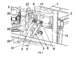
Fig. 4 showing another view with the safety cam that prevents arm movements outside a certain range. It also shows the coupling of the servomotor with the arms. -
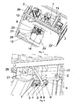
Fig. 5 showing the coupling of the arms with the platform through a set of bearings, shafts, bolts and stops equal to those of the upper part of the arm. -
Fig. 6 showing the platform on which the injection gun is positioned. -
Fig. 7 showing a separate arm, with a clearer view of the inner bore that has been made. It also shows a stop, which is inserted in the machined section and, through the corresponding hole, a shaft has been inserted, connecting it to the rod or platform, depending on the end of the arm, where said shaft has the holes for the bolts that connect the bearings fitted in the inner bores. It is noted that the different parts shown are not on the same scale, but rather have been expanded in varying degrees for easy viewing. - In view of the aforementioned figures and according to the numbering system that is adopted, they show a preferred realisation of the invention, which comprises the parts and elements indicated and described in detail below, where this example does not aim to limit the scope thereof in any way.
- The unit is anchored to a base plate (1) which in turn is supported by three pillars (13) positioned with an angular spacing of 120° between each one, so that there is space for positioning the remaining elements of the set of mechanical means for lining ends between said pillars (13).
- Thus, three servomotors (2) are positioned in the traditional delta robot configuration (120° separation between each one) anchored at the bottom of the base plate (1) by their respective support flanges (17). The axles of the servomotors (2) are joined to the rods (9) by means of conical couplings, which in turn transmit movement to the arms (3, 3') through a bolt (7) that passes through two separate stops (4) via a through-hole (19) and the cam (9) is connected to the bearings (6, 6') thanks to the shafts (5) joining said bearings (6, 6') through the respective shaft holes (18).
- As shown in
Figure 1 , the robot comprises a pair of arms (3, 3') whose ends have a machined section (15) with rectangular geometry housing the stop (4) which secures the connection with the bolt (5). The bearings (6, 6') are inserted on both sides of the machined section (15) through a bore (16) made from the inside out, so that the hole does not pass through completely and the bearings (6, 6') are flush against the outer wall of the arm. This ensures a robust coupling without gaps capable of withstanding high movement speeds without wear and tear. - The connection between the rod (9) and the arms (3, 3') will also have a lateral connection with a safety cam (26) whose mission is to accompany the movement of the rod (9) and limit the range of the arm movement, so that for any unexpected situation, excessive movements that may break the unit are avoided. The safety cam (26) will have safety stops (27) that restrict the range of rotation of said safety cam (26). The safety cam (26) is positioned in a casing box (20) which separates it from the other elements.
- The coupling of the arms (3, 3') by means of a pin (7) and stops (4) is repeated at both the top and the bottom. At the bottom, it is attached to the platform (8), which has three ends arranged with a 120° separation between each one and they all have a through-hole (14) for the bolt (7). In the centre of the platform, there is another hole for positioning the gun (10) which will house the injection gun body (11), into which the rubber will be fed under pressure for it to come out at the injector nozzle (12).
- The pillars (13) supporting the base plate (1) will be positioned on a bottom plate (21) with a central hole (22) of sufficient size to allow access by the injector nozzle (12) to the ends the feeder will position under said central hole (22). Thus, it will only be necessary to mount the bottom plate (21) on the bench of any machine using the systems referred to in the background section from which the lining parts have been removed to enable the implementation of the unit described in this memorandum, with the aforementioned benefits this entails.
- The bottom plate (21) will also have a base (23) for a wire cleaning brush (24). A self-cleaning process programmed into the robot moves the injection nozzle (12) to the position of the cleaning brush (24). By means of a repetitive movement, it applies pressure to the brush (24) and the nozzle (12) is cleaned completely, preventing obstructions that could cause deviations on the rubber outlet, staining the cover. Once the nozzle has been cleaned (12), it will move to a drain (28) for automatic purge so that the process can be resumed with all elements completely clean. Also, before a stop or a shift change during which the lining operation is expected to stop for an extended period, the nozzle (12) will be moved to the drain (28) and a jet of treated water will be passed through it to completely clean the inside of the gun body (11) and the injector nozzle (12), leaving both completely clean and ready for a restart when required.
- The gun body (11) will have connections for the inlet pipe for the injected rubber. The pipe will be flexible and long enough to follow the movements of the platform (8) without interruption.
- The entire unit described above will be covered by a protective casing (29) to prevent the penetration of foreign particles in the process and accidental access by workers to the moving parts of the mechanisms. Said casing (29) will also rest on the bottom plate (21).
- Having described the nature of this invention sufficiently, together with its implementation, it is not considered necessary to give a further explanation for any expert in the art to understand its scope and the benefits it provides, stating that, in its essence, it may be implemented via other realisations that differ in detail from that indicated by way of example, and which will also offer the protection indicated as long as its fundamental principle is not altered, changed or modified.
Claims (7)
- SET OF MECHANICAL MEANS THAT CAN BE INCORPORATED IN A ROBOT FOR LINING ENDS configured on the basis of a traditional delta robot with its respective servomotors (2) positioned with an angular spacing of 120° and a base plate (1) as support, which stands on pillars (13) which in turn rest on a bottom plate (21) positioned on a end feeder bench, characterised in that, at the output of the servomotors (2) there is a conical fastening connected to rods (9) which in turn transmit the movement to a symmetrical pair of arms (3, 3') connected at both ends by means of a bolt (7) which passes through said stops (4) via a through-hole (19) and the rod (14) is connected to bearings (6, 6') by shafts (5) that join said bearings (6, 6') through respective shaft holes (18); arranging the ends of the arms (3, 3') of a machined section (15) with rectangular geometry housing a stop (4) that secures the connection to the bolt (7) while bearings (6, 6') are inserted on both sides of the machined section (15) through a bore (16) made from the inside out, so that the hole is not complete and the bearings (6, 6') fit flush against the outer wall of the arm. The coupling of the arms (3, 3') by a bolt (7) and stops (4) is repeated at the lower end of the arms, this time to form the articulation with a platform (8), which has three ends positioned with a 120° angular spacing between each one, with a through-hole (18) for the bolt (7).
- SET OF MECHANICAL MEANS THAT CAN BE INCORPORATED IN A ROBOT FOR LINING ENDS according to claim 1, characterised in that the rod (9) connecting to the arms (3, 3') has a lateral connection to a safety cam (26) that rotates with the rod (9) and will be accompanied by safety stops (27) that limit the range of rotation of said safety cam (26).
- SET OF MECHANICAL MEANS THAT CAN BE INCORPORATED IN A ROBOT FOR LINING ENDS according to claim 1, characterised in that in the centre of the platform there is a hole (10) where the body of an injection gun (11) will be fitted, coupled to the injector nozzle (12) through which the rubber is to be applied.
- SET OF MECHANICAL MEANS THAT CAN BE INCORPORATED IN A ROBOT FOR LINING ENDS according to claims 1 and 3, characterised in that the bottom plate (21) has a central hole (22) of sufficient size to allow access by the injector nozzle (12) to the ends the feeder will position under said central hole (22); also having a fastening section (23) for a wire brush (24) to ensure the cleaning of the same and a drain (28).
- SET OF MECHANICAL MEANS THAT CAN BE INCORPORATED IN A ROBOT FOR LINING ENDS according to claims 1, 3 and 4, characterised in that the injector nozzle (12) is moved as programmed towards the position of the cleaning brush (24) and performs a repetitive movement to apply pressure to the brush (24).
- SET OF MECHANICAL MEANS THAT CAN BE INCORPORATED IN A ROBOT FOR LINING ENDS according to claims 1, 3 and 4, characterised in that, by means of a programmed movement of the injector nozzle (12), it moves to a drain (28), where it is cleaned by a jet of treated water.
- SET OF MECHANICAL MEANS THAT CAN BE INCORPORATED IN A ROBOT FOR LINING ENDS according to claims 1 to 4 characterised in that the entire unit is covered by a protective casing (29) that rests on the bottom plate (21).
Applications Claiming Priority (2)
| Application Number | Priority Date | Filing Date | Title |
|---|---|---|---|
| ES201300141U ES1078824Y (en) | 2013-02-08 | 2013-02-08 | Set of mechanical means that can be incorporated into a delta robot for the realization of lid gumming |
| PCT/ES2014/000003 WO2014122338A1 (en) | 2013-02-08 | 2014-01-08 | Set of mechanical means that can be incorporated into a delta robot for the gumming of lids |
Publications (3)
| Publication Number | Publication Date |
|---|---|
| EP2954985A1 true EP2954985A1 (en) | 2015-12-16 |
| EP2954985A4 EP2954985A4 (en) | 2018-08-01 |
| EP2954985B1 EP2954985B1 (en) | 2023-05-17 |
Family
ID=47748222
Family Applications (1)
| Application Number | Title | Priority Date | Filing Date |
|---|---|---|---|
| EP14749089.0A Active EP2954985B1 (en) | 2013-02-08 | 2014-01-08 | Delta robot for the gumming of lids |
Country Status (7)
| Country | Link |
|---|---|
| US (1) | US20150367505A1 (en) |
| EP (1) | EP2954985B1 (en) |
| CL (1) | CL2015002208A1 (en) |
| ES (2) | ES1078824Y (en) |
| MA (1) | MA38381B1 (en) |
| MX (1) | MX2015009990A (en) |
| WO (1) | WO2014122338A1 (en) |
Cited By (2)
| Publication number | Priority date | Publication date | Assignee | Title |
|---|---|---|---|---|
| CN106002947A (en) * | 2016-06-22 | 2016-10-12 | 安徽海思达机器人有限公司 | Carrying robot with freedom degrees which are arranged on same sides of slave arms and capable of being reconstructed |
| WO2017182756A1 (en) * | 2016-04-21 | 2017-10-26 | Sabatier S.A.S | Station for depositing a strip of material onto a cover and/or a base |
Families Citing this family (6)
| Publication number | Priority date | Publication date | Assignee | Title |
|---|---|---|---|---|
| CN104139390B (en) * | 2013-05-06 | 2016-04-27 | 鸿富锦精密工业(深圳)有限公司 | Robot |
| CN104191427A (en) * | 2014-08-22 | 2014-12-10 | 深圳大宇精雕科技有限公司 | Parallel mechanism arm |
| CN104369183A (en) * | 2014-11-19 | 2015-02-25 | 苏州赛腾精密电子有限公司 | Multidirectional mechanical arm |
| JP6698719B2 (en) * | 2018-02-14 | 2020-05-27 | ファナック株式会社 | Parallel link robot |
| JP7275752B2 (en) * | 2019-03-28 | 2023-05-18 | セイコーエプソン株式会社 | robot |
| ES3031668T3 (en) * | 2021-04-01 | 2025-07-10 | Autonox Holding Gmbh | Industrial robot |
Family Cites Families (21)
| Publication number | Priority date | Publication date | Assignee | Title |
|---|---|---|---|---|
| DE2530261C2 (en) | 1974-10-22 | 1986-10-23 | Asea S.p.A., Mailand/Milano | Programming device for a manipulator |
| GB2115778B (en) | 1982-01-15 | 1985-06-26 | Marconi Co Ltd | Mechanical actuators |
| DE69131427T2 (en) | 1991-05-28 | 1999-11-25 | Kabushiki Kaisha Toshiba, Kawasaki | WORKING DEVICE |
| US5605487A (en) * | 1994-05-13 | 1997-02-25 | Memc Electric Materials, Inc. | Semiconductor wafer polishing appartus and method |
| EP1878544A1 (en) * | 2006-07-11 | 2008-01-16 | CSEM Centre Suisse d'Electronique et de Microtechnique SA | Parallel positioning mechanism with articulated upper arm |
| JP4850863B2 (en) * | 2008-04-10 | 2012-01-11 | 村田機械株式会社 | Parallel mechanism |
| DE102008019966A1 (en) * | 2008-04-21 | 2009-10-22 | Elau Gmbh | Delta robot for packing lightweight foodstuff, has spring comprising hooks at both ends attached to pins in pivot connectors, and bracket formed at each pivot connector and connected with rods at both side pieces of bracket |
| EP2145586B1 (en) * | 2008-07-16 | 2014-12-31 | Brainlab AG | Adapter for mounting a medical device |
| DE102008063869A1 (en) * | 2008-12-19 | 2010-07-01 | Elau Gmbh | Delta robot with special arrangement of ball joints |
| CN102069495B (en) * | 2009-11-23 | 2014-01-22 | 鸿富锦精密工业(深圳)有限公司 | Parallel robot |
| DE102010009447A1 (en) | 2010-02-24 | 2011-08-25 | Fraunhofer-Gesellschaft zur Förderung der angewandten Forschung e.V., 80686 | joint |
| US20120171383A1 (en) * | 2010-12-30 | 2012-07-05 | Specialty Coating Systems, Inc. | Conformal coating apparatus and related method |
| EP2681016B1 (en) * | 2011-02-28 | 2017-07-19 | Technische Universität Dresden | Parallel robot and control method |
| ITBO20110221A1 (en) * | 2011-04-26 | 2012-10-27 | Marchesini Group Spa | DEVICE TO MOVE AND POSITION A MEMBER IN THE SPACE |
| JP5516615B2 (en) * | 2012-02-03 | 2014-06-11 | 株式会社安川電機 | Parallel link robot |
| JP5977136B2 (en) * | 2012-10-03 | 2016-08-24 | ヤマハ発動機株式会社 | Arm member and industrial robot provided with the arm member |
| JP5977137B2 (en) * | 2012-10-04 | 2016-08-24 | ヤマハ発動機株式会社 | Rotating shaft and industrial robot equipped with the rotating shaft |
| MX341585B (en) * | 2013-02-14 | 2016-08-25 | Automatische Technik México S A De C V * | Delta-type industrial robot. |
| TWI580541B (en) * | 2013-05-15 | 2017-05-01 | 台達電子工業股份有限公司 | Delta robot and linear delta mechanism |
| JP5849993B2 (en) * | 2013-06-07 | 2016-02-03 | 株式会社安川電機 | Parallel link robot, robot system, and transfer equipment construction method |
| EP2835226A1 (en) * | 2013-08-09 | 2015-02-11 | Yamaha Hatsudoki Kabushiki Kaisha | Wiring structure for robot arm |
-
2013
- 2013-02-08 ES ES201300141U patent/ES1078824Y/en not_active Expired - Fee Related
-
2014
- 2014-01-08 MX MX2015009990A patent/MX2015009990A/en unknown
- 2014-01-08 US US14/766,717 patent/US20150367505A1/en not_active Abandoned
- 2014-01-08 WO PCT/ES2014/000003 patent/WO2014122338A1/en not_active Ceased
- 2014-01-08 EP EP14749089.0A patent/EP2954985B1/en active Active
- 2014-01-08 ES ES14749089T patent/ES2952401T3/en active Active
-
2015
- 2015-08-07 CL CL2015002208A patent/CL2015002208A1/en unknown
- 2015-09-04 MA MA38381A patent/MA38381B1/en unknown
Non-Patent Citations (1)
| Title |
|---|
| See references of WO2014122338A1 * |
Cited By (6)
| Publication number | Priority date | Publication date | Assignee | Title |
|---|---|---|---|---|
| WO2017182756A1 (en) * | 2016-04-21 | 2017-10-26 | Sabatier S.A.S | Station for depositing a strip of material onto a cover and/or a base |
| FR3050392A1 (en) * | 2016-04-21 | 2017-10-27 | Sabatier S A S | STATION FOR DEPOSITING A CORD OF MATERIAL ON A COVER AND / OR BACKGROUND |
| CN109414812A (en) * | 2016-04-21 | 2019-03-01 | 萨巴蒂厄公司 | Station for depositing strips of material onto top and/or bottom |
| JP2019514719A (en) * | 2016-04-21 | 2019-06-06 | サバティエ・エス・ア・エス | Station for placing material strips on top and / or bottom |
| CN106002947A (en) * | 2016-06-22 | 2016-10-12 | 安徽海思达机器人有限公司 | Carrying robot with freedom degrees which are arranged on same sides of slave arms and capable of being reconstructed |
| CN106002947B (en) * | 2016-06-22 | 2018-05-15 | 安徽海思达机器人有限公司 | The transfer robot that a kind of slave arm homonymy arrangement free degree can reconstruct |
Also Published As
| Publication number | Publication date |
|---|---|
| ES1078824U (en) | 2013-03-13 |
| MA38381A1 (en) | 2016-06-30 |
| ES1078824Y (en) | 2013-06-10 |
| EP2954985A4 (en) | 2018-08-01 |
| MA38381B1 (en) | 2017-01-31 |
| CL2015002208A1 (en) | 2015-11-20 |
| EP2954985B1 (en) | 2023-05-17 |
| MX2015009990A (en) | 2016-01-15 |
| ES2952401T3 (en) | 2023-10-31 |
| WO2014122338A1 (en) | 2014-08-14 |
| US20150367505A1 (en) | 2015-12-24 |
Similar Documents
| Publication | Publication Date | Title |
|---|---|---|
| EP2954985B1 (en) | Delta robot for the gumming of lids | |
| Jiang et al. | State-of-the-Art control strategies for robotic PiH assembly | |
| CA2787300C (en) | Programmable robotic end effector system and method | |
| JP6691353B2 (en) | Lubricant injection system | |
| EP2729259B1 (en) | Pop-up nozzle, cleaning device and method of operation | |
| KR101948964B1 (en) | Cleaning apparatus | |
| CN106003147B (en) | Robot system and abnormality judgment method | |
| US20180043403A1 (en) | Method for machine-cleaning workpieces and/or machine components, and cleaning system | |
| US20180143098A1 (en) | Leak check system and method of checking leak using the same | |
| WO2016204158A1 (en) | Valve seat machining device, and valve seat machining method using said valve seat machining device | |
| CN110405728A (en) | Parallel Link Robot | |
| CN103153482A (en) | Repainting head for circular lids | |
| TW201607619A (en) | Apparatus and method for selectively applying a powdered coating to an internally threaded fastener | |
| JPWO2017217227A1 (en) | Grease changing method and grease suction device | |
| JP5077571B2 (en) | Operation method of powder supply device | |
| JP6649345B2 (en) | robot | |
| EP3490732B1 (en) | Machine for filling bottles and the like comprising handling device for washing and sanitising | |
| CN113939581A (en) | Production device, in particular for the pharmaceutical industry | |
| CN107107092B (en) | Rotary pass through for glue valve assembly | |
| WO2021166767A1 (en) | Structure of drive portion for relatively rotating plurality of structure portions and robot comprising joint portion | |
| US20250314514A1 (en) | Dosing head for a dosing system | |
| CN204953209U (en) | Robot is with crashproof airless spraying gun support | |
| KR101624698B1 (en) | Apparatus to supply welding tips | |
| CN109909099A (en) | Automatic spraying process | |
| JP2022085273A (en) | Lubricant supply system, lubricant supply method, industrial machine manufacturing method, and articulated robot manufacturing method |
Legal Events
| Date | Code | Title | Description |
|---|---|---|---|
| PUAI | Public reference made under article 153(3) epc to a published international application that has entered the european phase |
Free format text: ORIGINAL CODE: 0009012 |
|
| 17P | Request for examination filed |
Effective date: 20150904 |
|
| AK | Designated contracting states |
Kind code of ref document: A1 Designated state(s): AL AT BE BG CH CY CZ DE DK EE ES FI FR GB GR HR HU IE IS IT LI LT LU LV MC MK MT NL NO PL PT RO RS SE SI SK SM TR |
|
| AX | Request for extension of the european patent |
Extension state: BA ME |
|
| DAX | Request for extension of the european patent (deleted) | ||
| RIC1 | Information provided on ipc code assigned before grant |
Ipc: B25J 9/10 20060101ALI20180322BHEP Ipc: B25J 9/02 20060101AFI20180322BHEP |
|
| A4 | Supplementary search report drawn up and despatched |
Effective date: 20180702 |
|
| RIC1 | Information provided on ipc code assigned before grant |
Ipc: B25J 9/02 20060101AFI20180626BHEP Ipc: B25J 9/10 20060101ALI20180626BHEP |
|
| RIC1 | Information provided on ipc code assigned before grant |
Ipc: B25J 9/02 20060101AFI20191119BHEP Ipc: B25J 9/10 20060101ALI20191119BHEP |
|
| STAA | Information on the status of an ep patent application or granted ep patent |
Free format text: STATUS: EXAMINATION IS IN PROGRESS |
|
| 17Q | First examination report despatched |
Effective date: 20200625 |
|
| TPAC | Observations filed by third parties |
Free format text: ORIGINAL CODE: EPIDOSNTIPA |
|
| GRAP | Despatch of communication of intention to grant a patent |
Free format text: ORIGINAL CODE: EPIDOSNIGR1 |
|
| STAA | Information on the status of an ep patent application or granted ep patent |
Free format text: STATUS: GRANT OF PATENT IS INTENDED |
|
| INTG | Intention to grant announced |
Effective date: 20220503 |
|
| GRAS | Grant fee paid |
Free format text: ORIGINAL CODE: EPIDOSNIGR3 |
|
| GRAA | (expected) grant |
Free format text: ORIGINAL CODE: 0009210 |
|
| STAA | Information on the status of an ep patent application or granted ep patent |
Free format text: STATUS: THE PATENT HAS BEEN GRANTED |
|
| AK | Designated contracting states |
Kind code of ref document: B1 Designated state(s): AL AT BE BG CH CY CZ DE DK EE ES FI FR GB GR HR HU IE IS IT LI LT LU LV MC MK MT NL NO PL PT RO RS SE SI SK SM TR |
|
| REG | Reference to a national code |
Ref country code: GB Ref legal event code: FG4D |
|
| REG | Reference to a national code |
Ref country code: DE Ref legal event code: R096 Ref document number: 602014086972 Country of ref document: DE |
|
| REG | Reference to a national code |
Ref country code: CH Ref legal event code: EP |
|
| REG | Reference to a national code |
Ref country code: IE Ref legal event code: FG4D |
|
| REG | Reference to a national code |
Ref country code: AT Ref legal event code: REF Ref document number: 1568219 Country of ref document: AT Kind code of ref document: T Effective date: 20230615 |
|
| REG | Reference to a national code |
Ref country code: LT Ref legal event code: MG9D |
|
| REG | Reference to a national code |
Ref country code: NL Ref legal event code: MP Effective date: 20230517 |
|
| REG | Reference to a national code |
Ref country code: AT Ref legal event code: MK05 Ref document number: 1568219 Country of ref document: AT Kind code of ref document: T Effective date: 20230517 |
|
| PG25 | Lapsed in a contracting state [announced via postgrant information from national office to epo] |
Ref country code: SE Free format text: LAPSE BECAUSE OF FAILURE TO SUBMIT A TRANSLATION OF THE DESCRIPTION OR TO PAY THE FEE WITHIN THE PRESCRIBED TIME-LIMIT Effective date: 20230517 Ref country code: PT Free format text: LAPSE BECAUSE OF FAILURE TO SUBMIT A TRANSLATION OF THE DESCRIPTION OR TO PAY THE FEE WITHIN THE PRESCRIBED TIME-LIMIT Effective date: 20230918 Ref country code: NO Free format text: LAPSE BECAUSE OF FAILURE TO SUBMIT A TRANSLATION OF THE DESCRIPTION OR TO PAY THE FEE WITHIN THE PRESCRIBED TIME-LIMIT Effective date: 20230817 Ref country code: NL Free format text: LAPSE BECAUSE OF FAILURE TO SUBMIT A TRANSLATION OF THE DESCRIPTION OR TO PAY THE FEE WITHIN THE PRESCRIBED TIME-LIMIT Effective date: 20230517 Ref country code: AT Free format text: LAPSE BECAUSE OF FAILURE TO SUBMIT A TRANSLATION OF THE DESCRIPTION OR TO PAY THE FEE WITHIN THE PRESCRIBED TIME-LIMIT Effective date: 20230517 |
|
| REG | Reference to a national code |
Ref country code: ES Ref legal event code: FG2A Ref document number: 2952401 Country of ref document: ES Kind code of ref document: T3 Effective date: 20231031 |
|
| PG25 | Lapsed in a contracting state [announced via postgrant information from national office to epo] |
Ref country code: RS Free format text: LAPSE BECAUSE OF FAILURE TO SUBMIT A TRANSLATION OF THE DESCRIPTION OR TO PAY THE FEE WITHIN THE PRESCRIBED TIME-LIMIT Effective date: 20230517 Ref country code: PL Free format text: LAPSE BECAUSE OF FAILURE TO SUBMIT A TRANSLATION OF THE DESCRIPTION OR TO PAY THE FEE WITHIN THE PRESCRIBED TIME-LIMIT Effective date: 20230517 Ref country code: LV Free format text: LAPSE BECAUSE OF FAILURE TO SUBMIT A TRANSLATION OF THE DESCRIPTION OR TO PAY THE FEE WITHIN THE PRESCRIBED TIME-LIMIT Effective date: 20230517 Ref country code: LT Free format text: LAPSE BECAUSE OF FAILURE TO SUBMIT A TRANSLATION OF THE DESCRIPTION OR TO PAY THE FEE WITHIN THE PRESCRIBED TIME-LIMIT Effective date: 20230517 Ref country code: IS Free format text: LAPSE BECAUSE OF FAILURE TO SUBMIT A TRANSLATION OF THE DESCRIPTION OR TO PAY THE FEE WITHIN THE PRESCRIBED TIME-LIMIT Effective date: 20230917 Ref country code: HR Free format text: LAPSE BECAUSE OF FAILURE TO SUBMIT A TRANSLATION OF THE DESCRIPTION OR TO PAY THE FEE WITHIN THE PRESCRIBED TIME-LIMIT Effective date: 20230517 Ref country code: GR Free format text: LAPSE BECAUSE OF FAILURE TO SUBMIT A TRANSLATION OF THE DESCRIPTION OR TO PAY THE FEE WITHIN THE PRESCRIBED TIME-LIMIT Effective date: 20230818 |
|
| PG25 | Lapsed in a contracting state [announced via postgrant information from national office to epo] |
Ref country code: FI Free format text: LAPSE BECAUSE OF FAILURE TO SUBMIT A TRANSLATION OF THE DESCRIPTION OR TO PAY THE FEE WITHIN THE PRESCRIBED TIME-LIMIT Effective date: 20230517 |
|
| PG25 | Lapsed in a contracting state [announced via postgrant information from national office to epo] |
Ref country code: SK Free format text: LAPSE BECAUSE OF FAILURE TO SUBMIT A TRANSLATION OF THE DESCRIPTION OR TO PAY THE FEE WITHIN THE PRESCRIBED TIME-LIMIT Effective date: 20230517 |
|
| PG25 | Lapsed in a contracting state [announced via postgrant information from national office to epo] |
Ref country code: SM Free format text: LAPSE BECAUSE OF FAILURE TO SUBMIT A TRANSLATION OF THE DESCRIPTION OR TO PAY THE FEE WITHIN THE PRESCRIBED TIME-LIMIT Effective date: 20230517 Ref country code: SK Free format text: LAPSE BECAUSE OF FAILURE TO SUBMIT A TRANSLATION OF THE DESCRIPTION OR TO PAY THE FEE WITHIN THE PRESCRIBED TIME-LIMIT Effective date: 20230517 Ref country code: RO Free format text: LAPSE BECAUSE OF FAILURE TO SUBMIT A TRANSLATION OF THE DESCRIPTION OR TO PAY THE FEE WITHIN THE PRESCRIBED TIME-LIMIT Effective date: 20230517 Ref country code: EE Free format text: LAPSE BECAUSE OF FAILURE TO SUBMIT A TRANSLATION OF THE DESCRIPTION OR TO PAY THE FEE WITHIN THE PRESCRIBED TIME-LIMIT Effective date: 20230517 Ref country code: DK Free format text: LAPSE BECAUSE OF FAILURE TO SUBMIT A TRANSLATION OF THE DESCRIPTION OR TO PAY THE FEE WITHIN THE PRESCRIBED TIME-LIMIT Effective date: 20230517 Ref country code: CZ Free format text: LAPSE BECAUSE OF FAILURE TO SUBMIT A TRANSLATION OF THE DESCRIPTION OR TO PAY THE FEE WITHIN THE PRESCRIBED TIME-LIMIT Effective date: 20230517 |
|
| REG | Reference to a national code |
Ref country code: DE Ref legal event code: R097 Ref document number: 602014086972 Country of ref document: DE |
|
| PLBE | No opposition filed within time limit |
Free format text: ORIGINAL CODE: 0009261 |
|
| STAA | Information on the status of an ep patent application or granted ep patent |
Free format text: STATUS: NO OPPOSITION FILED WITHIN TIME LIMIT |
|
| 26N | No opposition filed |
Effective date: 20240220 |
|
| PG25 | Lapsed in a contracting state [announced via postgrant information from national office to epo] |
Ref country code: SI Free format text: LAPSE BECAUSE OF FAILURE TO SUBMIT A TRANSLATION OF THE DESCRIPTION OR TO PAY THE FEE WITHIN THE PRESCRIBED TIME-LIMIT Effective date: 20230517 |
|
| PG25 | Lapsed in a contracting state [announced via postgrant information from national office to epo] |
Ref country code: SI Free format text: LAPSE BECAUSE OF FAILURE TO SUBMIT A TRANSLATION OF THE DESCRIPTION OR TO PAY THE FEE WITHIN THE PRESCRIBED TIME-LIMIT Effective date: 20230517 |
|
| PG25 | Lapsed in a contracting state [announced via postgrant information from national office to epo] |
Ref country code: MC Free format text: LAPSE BECAUSE OF FAILURE TO SUBMIT A TRANSLATION OF THE DESCRIPTION OR TO PAY THE FEE WITHIN THE PRESCRIBED TIME-LIMIT Effective date: 20230517 |
|
| PG25 | Lapsed in a contracting state [announced via postgrant information from national office to epo] |
Ref country code: MC Free format text: LAPSE BECAUSE OF FAILURE TO SUBMIT A TRANSLATION OF THE DESCRIPTION OR TO PAY THE FEE WITHIN THE PRESCRIBED TIME-LIMIT Effective date: 20230517 |
|
| REG | Reference to a national code |
Ref country code: CH Ref legal event code: PL |
|
| PG25 | Lapsed in a contracting state [announced via postgrant information from national office to epo] |
Ref country code: LU Free format text: LAPSE BECAUSE OF NON-PAYMENT OF DUE FEES Effective date: 20240108 |
|
| GBPC | Gb: european patent ceased through non-payment of renewal fee |
Effective date: 20240108 |
|
| PG25 | Lapsed in a contracting state [announced via postgrant information from national office to epo] |
Ref country code: LU Free format text: LAPSE BECAUSE OF NON-PAYMENT OF DUE FEES Effective date: 20240108 |
|
| PG25 | Lapsed in a contracting state [announced via postgrant information from national office to epo] |
Ref country code: GB Free format text: LAPSE BECAUSE OF NON-PAYMENT OF DUE FEES Effective date: 20240108 |
|
| PG25 | Lapsed in a contracting state [announced via postgrant information from national office to epo] |
Ref country code: BE Free format text: LAPSE BECAUSE OF NON-PAYMENT OF DUE FEES Effective date: 20240131 |
|
| PG25 | Lapsed in a contracting state [announced via postgrant information from national office to epo] |
Ref country code: CH Free format text: LAPSE BECAUSE OF NON-PAYMENT OF DUE FEES Effective date: 20240131 |
|
| PG25 | Lapsed in a contracting state [announced via postgrant information from national office to epo] |
Ref country code: GB Free format text: LAPSE BECAUSE OF NON-PAYMENT OF DUE FEES Effective date: 20240108 Ref country code: CH Free format text: LAPSE BECAUSE OF NON-PAYMENT OF DUE FEES Effective date: 20240131 Ref country code: BE Free format text: LAPSE BECAUSE OF NON-PAYMENT OF DUE FEES Effective date: 20240131 |
|
| REG | Reference to a national code |
Ref country code: BE Ref legal event code: MM Effective date: 20240131 |
|
| PG25 | Lapsed in a contracting state [announced via postgrant information from national office to epo] |
Ref country code: BG Free format text: LAPSE BECAUSE OF FAILURE TO SUBMIT A TRANSLATION OF THE DESCRIPTION OR TO PAY THE FEE WITHIN THE PRESCRIBED TIME-LIMIT Effective date: 20230517 |
|
| PG25 | Lapsed in a contracting state [announced via postgrant information from national office to epo] |
Ref country code: BG Free format text: LAPSE BECAUSE OF FAILURE TO SUBMIT A TRANSLATION OF THE DESCRIPTION OR TO PAY THE FEE WITHIN THE PRESCRIBED TIME-LIMIT Effective date: 20230517 |
|
| PG25 | Lapsed in a contracting state [announced via postgrant information from national office to epo] |
Ref country code: IE Free format text: LAPSE BECAUSE OF NON-PAYMENT OF DUE FEES Effective date: 20240108 |
|
| PG25 | Lapsed in a contracting state [announced via postgrant information from national office to epo] |
Ref country code: IE Free format text: LAPSE BECAUSE OF NON-PAYMENT OF DUE FEES Effective date: 20240108 |
|
| PG25 | Lapsed in a contracting state [announced via postgrant information from national office to epo] |
Ref country code: CY Free format text: LAPSE BECAUSE OF FAILURE TO SUBMIT A TRANSLATION OF THE DESCRIPTION OR TO PAY THE FEE WITHIN THE PRESCRIBED TIME-LIMIT; INVALID AB INITIO Effective date: 20140108 |
|
| PG25 | Lapsed in a contracting state [announced via postgrant information from national office to epo] |
Ref country code: HU Free format text: LAPSE BECAUSE OF FAILURE TO SUBMIT A TRANSLATION OF THE DESCRIPTION OR TO PAY THE FEE WITHIN THE PRESCRIBED TIME-LIMIT; INVALID AB INITIO Effective date: 20140108 |
|
| PG25 | Lapsed in a contracting state [announced via postgrant information from national office to epo] |
Ref country code: TR Free format text: LAPSE BECAUSE OF FAILURE TO SUBMIT A TRANSLATION OF THE DESCRIPTION OR TO PAY THE FEE WITHIN THE PRESCRIBED TIME-LIMIT Effective date: 20230517 |
|
| PGFP | Annual fee paid to national office [announced via postgrant information from national office to epo] |
Ref country code: ES Payment date: 20260211 Year of fee payment: 13 |
|
| PGFP | Annual fee paid to national office [announced via postgrant information from national office to epo] |
Ref country code: DE Payment date: 20260219 Year of fee payment: 13 |
|
| PGFP | Annual fee paid to national office [announced via postgrant information from national office to epo] |
Ref country code: FR Payment date: 20260202 Year of fee payment: 13 |
|
| PGFP | Annual fee paid to national office [announced via postgrant information from national office to epo] |
Ref country code: IT Payment date: 20260512 Year of fee payment: 13 |