EP2954523B1 - Systems and methods of performing filtering for gain determination - Google Patents
Systems and methods of performing filtering for gain determination Download PDFInfo
- Publication number
- EP2954523B1 EP2954523B1 EP13753450.9A EP13753450A EP2954523B1 EP 2954523 B1 EP2954523 B1 EP 2954523B1 EP 13753450 A EP13753450 A EP 13753450A EP 2954523 B1 EP2954523 B1 EP 2954523B1
- Authority
- EP
- European Patent Office
- Prior art keywords
- band
- audio signal
- inter
- signal
- lsp
- Prior art date
- Legal status (The legal status is an assumption and is not a legal conclusion. Google has not performed a legal analysis and makes no representation as to the accuracy of the status listed.)
- Active
Links
- 238000001914 filtration Methods 0.000 title claims description 85
- 238000000034 method Methods 0.000 title claims description 65
- 230000005236 sound signal Effects 0.000 claims description 104
- 230000003044 adaptive effect Effects 0.000 claims description 25
- 230000003595 spectral effect Effects 0.000 claims description 25
- 238000013507 mapping Methods 0.000 claims description 17
- 230000004044 response Effects 0.000 claims description 12
- 230000000694 effects Effects 0.000 claims description 8
- 230000000875 corresponding effect Effects 0.000 description 52
- 238000012360 testing method Methods 0.000 description 28
- 230000005284 excitation Effects 0.000 description 22
- 230000001939 inductive effect Effects 0.000 description 21
- 238000001514 detection method Methods 0.000 description 11
- 238000012545 processing Methods 0.000 description 11
- 230000002123 temporal effect Effects 0.000 description 10
- 230000015572 biosynthetic process Effects 0.000 description 7
- 238000003786 synthesis reaction Methods 0.000 description 7
- 230000007704 transition Effects 0.000 description 6
- 101000712600 Homo sapiens Thyroid hormone receptor beta Proteins 0.000 description 5
- 102100033451 Thyroid hormone receptor beta Human genes 0.000 description 5
- 238000010586 diagram Methods 0.000 description 5
- 230000006870 function Effects 0.000 description 3
- 238000011045 prefiltration Methods 0.000 description 3
- 230000005540 biological transmission Effects 0.000 description 2
- 230000001413 cellular effect Effects 0.000 description 2
- 238000004891 communication Methods 0.000 description 2
- 238000013461 design Methods 0.000 description 2
- 230000008569 process Effects 0.000 description 2
- 230000002441 reversible effect Effects 0.000 description 2
- 238000012546 transfer Methods 0.000 description 2
- 230000006978 adaptation Effects 0.000 description 1
- 230000002238 attenuated effect Effects 0.000 description 1
- 230000002596 correlated effect Effects 0.000 description 1
- 238000005516 engineering process Methods 0.000 description 1
- 238000002156 mixing Methods 0.000 description 1
- 238000012986 modification Methods 0.000 description 1
- 230000004048 modification Effects 0.000 description 1
- 230000003287 optical effect Effects 0.000 description 1
- 238000013139 quantization Methods 0.000 description 1
- 238000012552 review Methods 0.000 description 1
- 238000005070 sampling Methods 0.000 description 1
- 238000001228 spectrum Methods 0.000 description 1
- 230000003068 static effect Effects 0.000 description 1
- 230000009466 transformation Effects 0.000 description 1
- 239000013598 vector Substances 0.000 description 1
- 230000002087 whitening effect Effects 0.000 description 1
Images


Classifications
-
- G—PHYSICS
- G10—MUSICAL INSTRUMENTS; ACOUSTICS
- G10L—SPEECH ANALYSIS OR SYNTHESIS; SPEECH RECOGNITION; SPEECH OR VOICE PROCESSING; SPEECH OR AUDIO CODING OR DECODING
- G10L19/00—Speech or audio signals analysis-synthesis techniques for redundancy reduction, e.g. in vocoders; Coding or decoding of speech or audio signals, using source filter models or psychoacoustic analysis
- G10L19/02—Speech or audio signals analysis-synthesis techniques for redundancy reduction, e.g. in vocoders; Coding or decoding of speech or audio signals, using source filter models or psychoacoustic analysis using spectral analysis, e.g. transform vocoders or subband vocoders
- G10L19/03—Spectral prediction for preventing pre-echo; Temporary noise shaping [TNS], e.g. in MPEG2 or MPEG4
-
- G—PHYSICS
- G10—MUSICAL INSTRUMENTS; ACOUSTICS
- G10L—SPEECH ANALYSIS OR SYNTHESIS; SPEECH RECOGNITION; SPEECH OR VOICE PROCESSING; SPEECH OR AUDIO CODING OR DECODING
- G10L19/00—Speech or audio signals analysis-synthesis techniques for redundancy reduction, e.g. in vocoders; Coding or decoding of speech or audio signals, using source filter models or psychoacoustic analysis
- G10L19/04—Speech or audio signals analysis-synthesis techniques for redundancy reduction, e.g. in vocoders; Coding or decoding of speech or audio signals, using source filter models or psychoacoustic analysis using predictive techniques
- G10L19/16—Vocoder architecture
- G10L19/18—Vocoders using multiple modes
- G10L19/24—Variable rate codecs, e.g. for generating different qualities using a scalable representation such as hierarchical encoding or layered encoding
-
- G—PHYSICS
- G10—MUSICAL INSTRUMENTS; ACOUSTICS
- G10L—SPEECH ANALYSIS OR SYNTHESIS; SPEECH RECOGNITION; SPEECH OR VOICE PROCESSING; SPEECH OR AUDIO CODING OR DECODING
- G10L21/00—Processing of the speech or voice signal to produce another audible or non-audible signal, e.g. visual or tactile, in order to modify its quality or its intelligibility
- G10L21/02—Speech enhancement, e.g. noise reduction or echo cancellation
- G10L21/0208—Noise filtering
-
- G—PHYSICS
- G10—MUSICAL INSTRUMENTS; ACOUSTICS
- G10L—SPEECH ANALYSIS OR SYNTHESIS; SPEECH RECOGNITION; SPEECH OR VOICE PROCESSING; SPEECH OR AUDIO CODING OR DECODING
- G10L19/00—Speech or audio signals analysis-synthesis techniques for redundancy reduction, e.g. in vocoders; Coding or decoding of speech or audio signals, using source filter models or psychoacoustic analysis
- G10L19/04—Speech or audio signals analysis-synthesis techniques for redundancy reduction, e.g. in vocoders; Coding or decoding of speech or audio signals, using source filter models or psychoacoustic analysis using predictive techniques
- G10L19/06—Determination or coding of the spectral characteristics, e.g. of the short-term prediction coefficients
- G10L19/07—Line spectrum pair [LSP] vocoders
-
- G—PHYSICS
- G10—MUSICAL INSTRUMENTS; ACOUSTICS
- G10L—SPEECH ANALYSIS OR SYNTHESIS; SPEECH RECOGNITION; SPEECH OR VOICE PROCESSING; SPEECH OR AUDIO CODING OR DECODING
- G10L21/00—Processing of the speech or voice signal to produce another audible or non-audible signal, e.g. visual or tactile, in order to modify its quality or its intelligibility
- G10L21/02—Speech enhancement, e.g. noise reduction or echo cancellation
- G10L21/0208—Noise filtering
- G10L21/0216—Noise filtering characterised by the method used for estimating noise
-
- G—PHYSICS
- G10—MUSICAL INSTRUMENTS; ACOUSTICS
- G10L—SPEECH ANALYSIS OR SYNTHESIS; SPEECH RECOGNITION; SPEECH OR VOICE PROCESSING; SPEECH OR AUDIO CODING OR DECODING
- G10L21/00—Processing of the speech or voice signal to produce another audible or non-audible signal, e.g. visual or tactile, in order to modify its quality or its intelligibility
- G10L21/02—Speech enhancement, e.g. noise reduction or echo cancellation
- G10L21/038—Speech enhancement, e.g. noise reduction or echo cancellation using band spreading techniques
- G10L21/0388—Details of processing therefor
Definitions
- the present disclosure is generally related to signal processing.
- wireless computing devices such as portable wireless telephones, personal digital assistants (PDAs), and paging devices that are small, lightweight, and easily carried by users.
- portable wireless telephones such as cellular telephones and Internet Protocol (IP) telephones
- IP Internet Protocol
- a wireless telephone can also include a digital still camera, a digital video camera, a digital recorder, and an audio file player.
- signal bandwidth In traditional telephone systems (e.g., public switched telephone networks (PSTNs)), signal bandwidth is limited to the frequency range of 300 Hertz (Hz) to 3.4 kiloHertz (kHz). In wideband (WB) applications, such as cellular telephony and voice over internet protocol (VoIP), signal bandwidth may span the frequency range from 50 Hz to 7 kHz. Super wideband (SWB) coding techniques support bandwidth that extends up to around 16 kHz. Extending signal bandwidth from narrowband telephony at 3.4 kHz to SWB telephony of 16 kHz may improve the quality of signal reconstruction, intelligibility, and naturalness.
- PSTNs public switched telephone networks
- SWB coding techniques typically involve encoding and transmitting the lower frequency portion of the signal (e.g., 50 Hz to 7 kHz, also called the "low-band").
- the low-band may be represented using filter parameters and/or a low-band excitation signal.
- the higher frequency portion of the signal e.g., 7 kHz to 16 kHz, also called the "high-band”
- a receiver may utilize signal modeling to predict the high-band.
- data associated with the high-band may be provided to the receiver to assist in the prediction.
- Such data may be referred to as "side information,” and may include gain information, line spectral frequencies (LSFs, also referred to as line spectral pairs (LSPs)), etc.
- LSFs line spectral frequencies
- High-band prediction using a signal model may be acceptably accurate when the low-band signal is sufficiently correlated to the high-band signal.
- the correlation between the low-band and the high-band may be weak, and the signal model may no longer be able to accurately represent the high-band. This may result in artifacts (e.g., distorted speech) at the receiver.
- An example of such a SWB coding technique can be found in published patent US 2005/0004793 A1 "Signal Adaptation for Higher Band coding Utilizing Band Split Coding".
- the described techniques include determining whether an audio signal to be encoded for transmission includes a component (e.g., noise) that may result in audible artifacts upon reconstruction of the audio signal.
- a component e.g., noise
- the underlying signal model may interpret the noise as speech data, which may result in an erroneous reconstruction of the audio signal.
- conditional filtering may be performed to a high-band portion of the audio signal and the filtered high-band output may be used to generate gain information for the high-band portion.
- the gain information based on the filtered high-band output may lead to reduced audible artifacts upon reconstruction of the audio signal at a receiver.
- a method in a particular embodiment, includes determining, based on spectral information corresponding to an audio signal that includes a low-band portion and a high-band portion, that the audio signal includes a component corresponding to an artifact-generating condition. The method also includes filtering the high-band portion of the audio signal to generate a filtered high-band output. The method further includes generating an encoded signal. Generating the encoded signal includes determining gain information based on a ratio of a first energy corresponding to the filtered high-band output to a second energy corresponding to a synthesized high-band signal generated based on the low-band portion and a modulated noise signal or to the low-band portion to reduce an audible effect of the artifact-generating condition.
- a method in a particular embodiment, includes comparing an inter-line spectral pair (LSP) spacing associated with a frame of an audio signal to at least one threshold. The method also includes conditional filtering of a high-band portion of the audio signal to generate a filtered high-band output based at least partially on the comparing. The method includes determining gain information based on a ratio of a first energy corresponding to the filtered high-band output to a second energy corresponding to a low-band portion of the audio signal.
- LSP inter-line spectral pair
- an apparatus in another particular embodiment, includes means for determining, based on spectral information corresponding to an audio signal that includes a low-band portion and a high-band portion, that the audio signal includes a component corresponding to an artifact-generating condition.
- the apparatus also includes means for filtering a high-band portion of the audio signal to generate a filtered high-band output.
- the apparatus includes means for generating an encoded signal.
- the means for generating the encoded signal includes means for determining gain information based on a ratio of a first energy corresponding to the filtered high-band output to a second energy corresponding to the low-band portion to reduce an audible effect of the artifact-generating condition.
- a non-transitory computer-readable medium includes instructions that, when executed by a computer, cause the computer to determine, based on spectral information corresponding to an audio signal that includes a low-band portion and a high-band portion, that the audio signal includes a component corresponding to an artifact-generating condition, to filter the high-band portion of the audio signal to generate a filtered high-band output, and to generate an encoded signal.
- Generating the encoded signal includes determining gain information based on a ratio of a first energy corresponding to the filtered high-band output to a second energy corresponding to a synthesized high-band signal generated based on the low-band portion and a modulated noise signal or to the low-band portion to reduce an audible effect of the artifact-generating condition.
- At least one of the disclosed embodiments include an ability to detect artifact-inducing components (e.g., noise) and to selectively perform filtering in response to detecting such artifact-inducing components to affect gain information, which may result in more accurate signal reconstruction at a receiver and fewer audible artifacts.
- artifact-inducing components e.g., noise
- filtering in response to detecting such artifact-inducing components to affect gain information, which may result in more accurate signal reconstruction at a receiver and fewer audible artifacts.
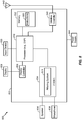
- a particular embodiment of a system that is operable to perform filtering is shown and generally designated 100.
- the system 100 may be integrated into an encoding system or apparatus (e.g., in a wireless telephone or coder/decoder (CODEC)).
- CDA coder/decoder
- FIG. 1 various functions performed by the system 100 of FIG. 1 are described as being performed by certain components or modules. However, this division of components and modules is for illustration only. In an alternate embodiment, a function performed by a particular component or module may instead be divided amongst multiple components or modules. Moreover, in an alternate embodiment, two or more components or modules of FIG. 1 may be integrated into a single component or module. Each component or module illustrated in FIG. 1 may be implemented using hardware (e.g., a field-programmable gate array (FPGA) device, an application-specific integrated circuit (ASIC), a digital signal processor (DSP), a controller, etc.), software (e.g., instructions executable by a processor), or any combination thereof.
- FPGA field-programmable gate array
- ASIC application-specific integrated circuit
- DSP digital signal processor
- controller e.g., a controller, etc.
- software e.g., instructions executable by a processor
- the system 100 includes an analysis filter bank 110 that is configured to receive an input audio signal 102.
- the input audio signal 102 may be provided by a microphone or other input device.
- the input audio signal 102 may include speech.
- the input audio signal may be a super wideband (SWB) signal that includes data in the frequency range from approximately 50 hertz (Hz) to approximately 16 kilohertz (kHz).
- SWB super wideband
- the analysis filter bank 110 may filter the input audio signal 102 into multiple portions based on frequency.
- the analysis filter bank 110 may generate a low-band signal 122 and a high-band signal 124.
- the low-band signal 122 and the high-band signal 124 may have equal or unequal bandwidths, and may be overlapping or non-overlapping.
- the analysis filter bank 110 may generate more than two outputs.
- the low-band signal 122 and the high-band signal 124 may occupy non-overlapping frequency bands.
- the low-band signal 122 and the high-band signal 124 may occupy non-overlapping frequency bands of 50 Hz - 7 kHz and 7 kHz - 16 kHz.
- the low-band signal 122 and the high-band signal 124 may occupy non-overlapping frequency bands of 50 Hz - 8 kHz and 8 kHz - 16 kHz.
- the low-band signal 122 and the high-band signal 124 may overlap (e.g., 50 Hz - 8 kHz and 7 kHz - 16 kHz), which may enable a low-pass filter and a high-pass filter of the analysis filter bank 110 to have a smooth rolloff, which may simplify design and reduce cost of the low-pass filter and the high-pass filter. Overlapping the low-band signal 122 and the high-band signal 124 may also enable smooth blending of low-band and high-band signals at a receiver, which may result in fewer audible artifacts.
- the input audio signal 102 may be a wideband (WB) signal having a frequency range of approximately 50 Hz to approximately 8 kHz.
- the low-band signal 122 may correspond to a frequency range of approximately 50 Hz to approximately 6.4 kHz and the high-band signal 124 may correspond to a frequency range of approximately 6.4 kHz to approximately 8 kHz.
- the various systems and methods herein are described as detecting high-band noise and performing various operations in response to high-band noise. However, this is for example only. The techniques illustrated with reference to FIGS. 1-7 may also be performed in the context of low-band noise.
- the system 100 may include a low-band analysis module 130 configured to receive the low-band signal 122.
- the low-band analysis module 130 may represent an embodiment of a code excited linear prediction (CELP) encoder.
- the low-band analysis module 130 may include a linear prediction (LP) analysis and coding module 132, a linear prediction coefficient (LPC) to line spectral pair (LSP) transform module 134, and a quantizer 136.
- LSPs may also be referred to as line spectral frequencies (LSFs), and the two terms may be used interchangeably herein.
- the LP analysis and coding module 132 may encode a spectral envelope of the low-band signal 122 as a set of LPCs.
- LPCs may be generated for each frame of audio (e.g., 20 milliseconds (ms) of audio, corresponding to 320 samples at a sampling rate of 16 kHz), each sub-frame of audio (e.g., 5 ms of audio), or any combination thereof.
- the number of LPCs generated for each frame or sub-frame may be determined by the "order" of the LP analysis performed.
- the LP analysis and coding module 132 may generate a set of eleven LPCs corresponding to a tenth-order LP analysis.
- the LPC to LSP transform module 134 may transform the set of LPCs generated by the LP analysis and coding module 132 into a corresponding set of LSPs (e.g., using a one-to-one transform). Alternately, the set of LPCs may be one-to-one transformed into a corresponding set of parcor coefficients, log-area-ratio values, immittance spectral pairs (ISPs), or immittance spectral frequencies (ISFs). The transform between the set of LPCs and the set of LSPs may be reversible without error.
- the quantizer 136 may quantize the set of LSPs generated by the transform module 134.
- the quantizer 136 may include or be coupled to multiple codebooks that include multiple entries (e.g., vectors).
- the quantizer 136 may identify entries of codebooks that are "closest to" (e.g., based on a distortion measure such as least squares of mean square error) the set of LSPs.
- the quantizer 136 may output an index value or series of index values corresponding to the location of the identified entries in the codebooks.
- the output of the quantizer 136 may thus represent low-band filter parameters that are included in a low-band bit stream 142.
- the low-band analysis module 130 may also generate a low-band excitation signal 144.
- the low-band excitation signal 144 may be an encoded signal that is generated by quantizing a LP residual signal that is generated during the LP process performed by the low-band analysis module 130.
- the LP residual signal may represent prediction error.
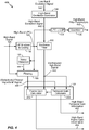
- the system 100 may further include a high-band analysis module 150 configured to receive the high-band signal 124 from the analysis filter bank 110 and the low-band excitation signal 144 from the low-band analysis module 130.
- the high-band analysis module 150 may generate high-band side information 172 based on one or more of the high-band signal 124, the low-band excitation signal 144, or a high-band filtered output 168, such as described in further detail with respect to FIG. 4 .
- the high-band side information 172 may include high-band LSPs and/or gain information (e.g., based on at least a ratio of high-band energy to low-band energy), as further described herein.
- the high-band analysis module 150 may include a high-band excitation generator 160.
- the high-band excitation generator 160 may generate a high-band excitation signal by extending a spectrum of the low-band excitation signal 144 into the high-band frequency range (e.g., 7 kHz - 16 kHz).
- the high-band excitation generator 160 may apply a transform to the low-band excitation signal (e.g., a non-linear transform such as an absolute-value or square operation) and may mix the transformed low-band excitation signal with a noise signal (e.g., white noise modulated according to an envelope corresponding to the low-band excitation signal 144) to generate the high-band excitation signal.
- the high-band excitation signal may be used by a high-band gain determination module 162 to determine one or more high-band gain parameters that are included in the high-band side information 172.
- the high-band analysis module 150 may also include an LP analysis and coding module 152, a LPC to LSP transform module 154, and a quantizer 156.
- Each of the LP analysis and coding module 152, the transform module 154, and the quantizer 156 may function as described above with reference to corresponding components of the low-band analysis module 130, but at a comparatively reduced resolution (e.g., using fewer bits for each coefficient, LSP, etc.).
- the high band LSP Quantizer 156 may use scalar quantization where a subset of LSP coefficients are quantized individually using a pre-defined number of bits.
- the LP analysis and coding module 152, the transform module 154, and the quantizer 156 may use the high-band signal 124 to determine high-band filter information (e.g., high-band LSPs) that are included in the high-band side information 172.
- the high-band side information 172 may include high-band LSPs as well as high-band gain parameters.
- the low-band bit stream 142 and the high-band side information 172 may be multiplexed by a multiplexer (MUX) 180 to generate an output bit stream 192.
- the output bit stream 192 may represent an encoded audio signal corresponding to the input audio signal 102.
- the output bit stream 192 may be transmitted (e.g., over a wired, wireless, or optical channel) and/or stored.
- reverse operations may be performed by a demultiplexer (DEMUX), a low-band decoder, a high-band decoder, and a filter bank to generate an audio signal (e.g., a reconstructed version of the input audio signal 102 that is provided to a speaker or other output device).
- the number of bits used to represent the low-band bit stream 142 may be substantially larger than the number of bits used to represent the high-band side information 172. Thus, most of the bits in the output bit stream 192 represent low-band data.
- the high-band side information 172 may be used at a receiver to regenerate the high-band excitation signal from the low-band data in accordance with a signal model.
- the signal model may represent an expected set of relationships or correlations between low-band data (e.g., the low-band signal 122) and high-band data (e.g., the high-band signal 124).
- different signal models may be used for different kinds of audio data (e.g., speech, music, etc.), and the particular signal model that is in use may be negotiated by a transmitter and a receiver (or defined by an industry standard) prior to communication of encoded audio data.
- the high-band analysis module 150 at a transmitter may be able to generate the high-band side information 172 such that a corresponding high-band analysis module at a receiver is able to use the signal model to reconstruct the high-band signal 124 from the output bit stream 192.
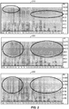
- a first spectrogram 210 in FIG. 2 illustrates an audio signal having components corresponding to artifact-generating conditions, illustrated as high-band noise having a relatively large signal energy.
- a second spectrogram 220 illustrates the resulting artifacts in the reconstructed signal due to overestimation of gain parameters.
- the high-band analysis module 150 may perform a conditional high-band filtering.
- the high-band analysis module 150 may include an artifact inducing component detection module 158 that is configured to detect artifact-inducing components, e.g., the artifact-inducing component shown in the first spectrogram 210 of FIG. 2 , that are likely to result in audible artifacts upon reproduction.
- a filtering module 166 may perform filtering of the high-band signal 124 to attenuate artifact-generating components. Filtering the high-band signal 124 may result in a reconstructed signal according to a third spectrogram 230 of FIG. 2 , which is free of (or has a reduced level of) the artifacts shown in the second spectrogram 220 of FIG. 2 .
- a first test may include comparing a minimum inter-LSP spacing that is detected in a set of LSPs (e.g., LSPs for a particular frame of the audio signal) to a first threshold.
- LSPs e.g., LSPs for a particular frame of the audio signal
- a small spacing between LSPs corresponds to a relatively strong signal at a relatively narrow frequency range.
- an artifact-generating condition is determined to be present in the audio signal and filtering may be enabled for the frame.
- a second test may include comparing an average minimum inter-LSP spacing for multiple consecutive frames to a second threshold. For example, when a particular frame of an audio signal has a minimum LSP spacing that is greater than the first threshold but less than a second threshold, an artifact-generating condition may still be determined to be present if an average minimum inter-LSP spacing for multiple frames (e.g., a weighted average of the minimum inter-LSP spacing for the four most recent frames including the particular frame) is smaller than a third threshold. As a result, filtering may be enabled for the particular frame.
- an average minimum inter-LSP spacing for multiple frames e.g., a weighted average of the minimum inter-LSP spacing for the four most recent frames including the particular frame
- a third test may include determining if a particular frame follows a filtered frame of the audio signal. If the particular frame follows a filtered frame, filtering may be enabled for the particular frame based on the minimum inter-LSP spacing of the particular frame being less than the second threshold.
- Filtering for a frame may be enabled in response to any one or more of the tests (or combinations of the tests) being satisfied or in response to one or more other tests or conditions being satisfied.
- a particular embodiment may include determining whether or not to enable filtering based on a single test, such as the first test described above, without applying either of the second test or the third test.
- Alternate embodiments may include determining whether or not to enable filtering based on the second test without applying either of the first test or the third test, or based on the third test without applying either of the first test or the second test.
- a particular embodiment may include determining whether or not to enable filtering based on two tests, such as the first test and the second test, without applying the third test. Alternate embodiments may include determining whether or not to enable filtering based on the first test and the third test without applying the second test, or based on the second test and the third test without applying the first test.
- the artifact inducing component detection module 158 may determine parameters from the audio signal to determine whether an audio signal includes a component that will result in audible artifacts. Examples of such parameters include a minimum inter-LSP spacing and an average minimum inter-LSP spacing. For example, a tenth order LP process may generate a set of eleven LPCs that are transformed to ten LSPs. The artifact inducing component detection module 158 may determine, for a particular frame of audio, a minimum (e.g., smallest) spacing between any two of the ten LSPs.
- the artifact inducing component detection module 158 may determine a minimum inter-LSP spacing and an average minimum inter-LSP spacing, as shown in the following C++-style pseudocode that may be executed by or implemented by the artifact inducing component detection module 158.
- the artifact inducing component detection module 158 may further determine a weighted-average minimum inter-LSP spacing in accordance with the following pseudocode.
- the following pseudocode also includes resetting inter-LSP spacing in response to a mode transition.
- mode transitions may occur in devices that support multiple encoding modes for music and/or speech.
- the device may use an algebraic CELP (ACELP) mode for speech and an audio coding mode, i.e., a generic signal coding (GSC) for music-type signals.
- ACELP algebraic CELP
- GSC generic signal coding
- the device may determine based on feature parameters (e.g., tonality, pitch drift, voicing, etc.) that an ACELP/GSC/modified discrete cosine transform (MDCT) mode may be used.
- feature parameters e.g., tonality, pitch drift, voicing, etc.
- MDCT discrete cosine transform
- the artifact inducing component detection module 158 may compare the determined values to one or more thresholds in accordance with the following pseudocode to determine whether artifact-inducing noise exists in the frame of audio. When artifact-inducing noise exists, the artifact inducing component detection module 158 may cause the filtering module 166 to perform filtering of the high-band signal 124.
- the conditional filtering module 166 may selectively perform filtering when artifact-inducing noise is detected.
- the filtering module 166 may filter the high-band signal 124 prior to determination of one or more gain parameters of the high-band side information 172.
- the filtering may include finite impulse response (FIR) filtering.
- the filtering may be performed using adaptive high-band LPCs 164 from the LP analysis and coding module 152 and may generate a high-band filtered output 168.
- the high-band filtered output 168 may be used to generate at least a portion of the high-band side information 172.
- the weighting parameter ⁇ may have a constant value.
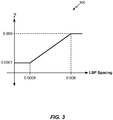
- the weighting parameter ⁇ may be adaptive and may be determined based on inter-LSP spacing. For example, a value of the weighting parameter ⁇ may be determined from the linear mapping of ⁇ to inter-LSP spacing illustrated by the graph 300 of FIG. 3 .
- mapping of FIG. 3 may be adaptive based on one or more factors, such as the sample rate and frequency at which artifacts are prominent, signal-to-noise ratio (SNR), prediction gain after LP analysis, etc.
- SNR signal-to-noise ratio
- the system 100 of FIG. 1 may thus perform filtering to reduce or prevent audible artifacts due to noise in an input signal.
- the system 100 of FIG. 1 may thus enable more accurate reproduction of an audio signal in the presence of an artifact generating noise component that is unaccounted for by speech coding signal models.
- FIG. 4 illustrates an embodiment of a system 400 configured to filter a high-band signal.
- the system 400 includes the LP analysis and coding module 152, the LPC to LSP transform module 154, the quantizer 156, the artifact inducing component detection module 158, and the filtering module 166 of FIG. 1 .
- the system 400 further includes a synthesis filter 402, a frame gain calculator 404, and a temporal gain calculator 406.
- the frame gain calculator 404 and the temporal gain calculator 406 are components of the gain determination module 162 of FIG. 1 .
- the high-band signal 124 (e.g., the high-band portion of the input signal 102 of FIG. 1 ) is received at the LP analysis and coding module 152, and the LP analysis and coding module 152 generates the high-band LPCs 164, as described with respect to FIG. 1 .
- the high-band LPCs 164 are converted to LSPs at the LPC to LSP transform module 154, and the LSPs are quantized at the quantizer 156 to generate high-band filter parameters 450 (e.g., quantized LSPs).
- the synthesis filter 402 is used to emulate decoding of the high-band signal based on the low-band excitation signal 144 and the high-band LPCs 164.
- the low-band excitation signal 144 may be transformed and mixed with a modulated noise signal at the high-band excitation generator 160 to generate a high-band excitation signal 440.
- the high-band excitation signal 440 is provided as an input to the synthesis filter 402, which is configured according to the high-band LPCs 164 to generate a synthesized high-band signal 442.
- the synthesis filter 402 is illustrated as receiving the high-band LPCs 164, in other embodiments the LSPs output by the LPC to LSP transformation module 154 may be transformed back to LPCs and provided to the synthesis filter 402. Alternatively, the output of the quantizer 156 may be un-quantized, transformed back to LPCs, and provided to the synthesis filter 402, to more accurately emulate reproduction of the LPCs that occurs at a receiving device.
- the synthesized high-band signal 442 may traditionally be compared to the high-band signal 124 to generate gain information for high-band side information
- gain information may be used to attenuate the artifact-generating component by use of a selectively filtered high-band signal 446.
- the filtering module 166 may be configured to receive a control signal 444 from the artifact inducing component detection module 158.
- the control signal 444 may include a value corresponding to a smallest detected inter-LSP spacing
- the filtering module 166 may selectively apply filtering based on the minimum detected inter-LSP spacing to generate a filtered high-band output as the selectively filtered high-band signal 446.
- the filtering module 166 may apply filtering to generate a filtered high-band output as the selectively filtered high-band signal 446 using a value of the inter-LSP spacing to determine a value of the weighting factor y, such as according to the mapping illustrated in FIG. 3 .
- a selectively and/or adaptively filtered high-band signal 446 may have reduced signal energy as compared to the high-band signal 124 when artifact-generating noise components are detected in the high-band signal 124.
- the selectively and/or adaptively filtered high-band signal 446 may be compared to the synthesized high-band signal 442 and/or compared to the low band signal 122 of FIG. 1 at the frame gain calculator 404.
- the frame gain calculator 404 may generate high-band frame gain information 454 based on the comparison (e.g., an encoded or quantized ratio of energy values, such as a ratio of a first energy corresponding to the filtered high-band output to a second energy corresponding to the low-band signal) to enable a receiver to adjust a frame gain to more closely reproduce the filtered high-band signal 446 during reconstruction of the high-band signal 124.
- the high-band signal 124 By filtering the high-band signal 124 prior to determining the high-band frame gain information, audible effects of artifacts due to noise in the high-band signal 124 may be attenuated or eliminated.
- the synthesized high-band signal 442 may also be provided to the temporal gain calculator 406.
- the temporal gain calculator 406 may determine a ratio of an energy corresponding to the synthesized high-band signal and/or an energy corresponding to the low band signal 122 of FIG. 1 to an energy corresponding to the filtered high-band signal 446.
- the ratio may be encoded (e.g., quantized) and provided as high-band temporal gain information 452 corresponding to sub-frame gain estimates.
- the high-band temporal gain information may enable a receiver to adjust a high-band gain to more closely reproduce a high-band-to-low-band energy ratio of an input audio signal.
- the high-band filter parameters 450, the high-band temporal gain information 452, and the high-band frame gain information 454 may collectively correspond to the high-band side information 172 of FIG. 1 .
- Some of the side information, such as the high-band frame gain information 454, may be at least partially based on the filtered signal 446 and at least partially based on the synthesized high-band signal 442. Some of the side information may not be affected by the filtering.
- the filtered high-band output of the filter 166 may be used only for determining gain information.
- the selectively filtered high-band signal 466 is provided only to the high-band gain determination module 162 and is not provided to the LP analysis and coding module 152 for encoding.
- the LSPs e.g., the high-band filter parameters 450
- the LSPs are generated at least partially based on the high-band signal 124 and may not be affected by the filtering.
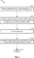
- FIG. 5 a flowchart of a particular embodiment of a method of performing filtering is shown and generally designated 500.
- the method 500 may be performed at the system 100 of FIG. 1 or the system 400 of FIG. 4 .
- the method 500 may include receiving an audio signal to be reproduced (e.g., a speech coding signal model), at 502.
- the audio signal may have a bandwidth from approximately 50 Hz to approximately 16 kHz and may include speech.
- the analysis filter bank 110 may receive the input audio signal 102 that is to be reproduced at a receiver.
- the method 500 may include determining, based on spectral information corresponding to the audio signal, that the audio signal includes a component corresponding to an artifact-generating condition, at 504.
- the audio signal may be determined to include the component corresponding to an artifact-generating condition in response to the inter-LSP spacing being less than a first threshold, such as "THR2" in the pseudocode corresponding to FIG. 1 .
- An average inter-LSP spacing may be determined based on the inter-LSP spacing associated with the frame and at least one other inter-LSP spacing associated with at least one other frame of the audio signal.
- the audio signal may be determined to include the component corresponding to an artifact-generating condition in response to the inter-LSP spacing being less than a second threshold and at least one of: the average inter-LSP spacing being less than a third threshold or a gain attenuation corresponding to another frame of the audio signal being enabled, the other frame preceding the frame of the audio signal.
- the method 500 includes filtering the audio signal, at 506.
- the audio signal may include a low-band portion and a high-band portion, such as the low-band signal 122 and the high-band signal 124 of FIG. 1 .
- Filtering the audio signal may include filtering the high-band portion.
- the audio signal may be filtered using adaptive linear prediction coefficients (LPCs) associated with a high-band portion of the audio signal to generate a high-band filtered output.
- LPCs adaptive linear prediction coefficients
- the LPCs may be used in conjunction with the weighting parameter ⁇ as described with respect to FIG. 1 .
- an inter-line spectral pair (LSP) spacing associated with a frame of the audio signal may be determined as a smallest of a plurality of inter-LSP spacings corresponding to a plurality of LSPs generated during linear predictive coding (LPC) of the frame.
- the method 500 may include determining an adaptive weighting factor based on the inter-LSP spacing and performing the filtering using the adaptive weighting factor.
- the adaptive weighting factor may be applied to high-band linear prediction coefficients, such as by applying the term (1- ⁇ ) i to the linear prediction coefficients ⁇ i as described with respect to the filter equation described with respect to FIG. 1 .
- the adaptive weighting factor may be determined according to a mapping that associates inter-LSP spacing values to values of the adaptive weighting factor, such as illustrated in FIG. 3 .
- the mapping may be a linear mapping such that a linear relationship exists between a range of inter-LSP spacing values and a range of weighting factor values.
- the mapping may be non-linear.
- the mapping may be static (e.g., the mapping of FIG. 3 may apply under all operating conditions) or may be adaptive (e.g., the mapping of FIG. 3 may vary based on operating conditions).
- the mapping may be adaptive based on at least one of a sample rate or a frequency corresponding to the artifact-generating condition.
- the mapping may be adaptive based on a signal-to-noise ratio.
- the mapping may be adaptive based on a prediction gain after linear prediction analysis.
- the method 500 may include generating an encoded signal based on the filtering to reduce an audible effect of the artifact-generating condition, at 508.
- the method 500 ends, at 510.
- the method 500 may be performed by the system 100 of FIG. 1 or the system 400 of FIG. 4 .
- the input audio signal 102 may be received at the analysis filter bank 110, and the low-band portion and the high-band portion may be generated at the analysis filter bank 110.
- the low-band analysis module 130 may generate the low-band bit stream 142 based on the low-band portion.
- the high-band analysis module 150 may generate the high-band side information 172 based on at least one of the high-band portion 124, the low-band excitation signal 144 associated with the low-band portion, or the high-band filtered output 168.
- the MUX 180 may multiplex the low-band bit stream 142 and the high-band side information 172 to generate the output bit stream 192 corresponding to the encoded signal.
- the high-band side information 172 of FIG. 1 may include frame gain information that is generated at least partially based on the high-band filtered output 168 and on the high-band portion, such as described with respect to the high-band frame gain information 454 of FIG. 4 .
- the high-band side information 172 may further include temporal gain information corresponding to sub-frame gain estimates.
- the temporal gain information may be generated at least partially based on the high-band portion 124 and the high-band filtered output 168, such as described with respect to the high-band temporal gain information 452 of FIG. 4 .
- the high-band side information 172 may include line spectral pairs (LSPs) generated at least partially based on the high-band portion 124, such as described with respect to the high-band filter parameters 450 of FIG. 4 .
- LSPs line spectral pairs
- the method 500 of FIG. 5 may be implemented via hardware (e.g., a field-programmable gate array (FPGA) device, an application-specific integrated circuit (ASIC), etc.) of a processing unit such as a central processing unit (CPU), a digital signal processor (DSP), or a controller, via a firmware device, or any combination thereof.
- a processing unit such as a central processing unit (CPU), a digital signal processor (DSP), or a controller
- DSP digital signal processor
- the method 500 of FIG. 5 can be performed by a processor that executes instructions, as described with respect to FIG. 8 .
- a flowchart of a particular embodiment of a method of performing filtering is shown and generally designated 600.
- the method 600 may be performed at the system 100 of FIG. 1 or the system 400 of FIG. 4 .
- An inter-line spectral pair (LSP) spacing associated with a frame of an audio signal is compared to at least one threshold, at 602, and the audio signal may be filtered based at least partially on a result of the comparing, at 604.
- comparing the inter-LSP spacing to at least one threshold may indicate the presence of an artifact-generating component in the audio signal, the comparison need not indicate, detect, or require the actual presence of an artifact-generating component.
- one or more thresholds used in the comparison may be set to provide an increased likelihood that gain control is performed when an artifact-generating component is present in the audio signal while also providing an increased likelihood that filtering is performed without an artifact-generating component being present in the audio signal (e.g., a 'false positive').
- the method 600 may perform filtering without determining whether an artifact-generating component is present in the audio signal.
- An inter-line spectral pair (LSP) spacing associated with a frame of the audio signal may be determined as a smallest of a plurality of inter-LSP spacings corresponding to a plurality of LSPs generated during linear predictive coding (LPC) of the frame.
- the audio signal may be filtered in response to the inter-LSP spacing being less than a first threshold.
- the audio signal may be filtered in response to the inter-LSP spacing being less than a second threshold and at least one of: an average inter-LSP spacing being less than a third threshold, the average inter-LSP spacing based on the inter-LSP spacing associated with the frame and at least one other inter-LSP spacing associated with at least one other frame of the audio signal, or filtering corresponding to another frame of the audio signal being enabled, the other frame preceding the frame of the audio signal.
- Filtering the audio signal may include filtering the audio signal using adaptive linear prediction coefficients (LPCs) associated with a high-band portion of the audio signal to generate high-band filtered output.
- the filtering may be performed using an adaptive weighting factor.
- the adaptive weighting factor may be determined based on the inter-LSP spacing, such as the adaptive weighting factor ⁇ described with respect to FIG. 3 .
- the adaptive weighting factor may be determined according to a mapping that associates inter-LSP spacing values to values of the adaptive weighting factor.
- Filtering the audio signal may include applying the adaptive weighting factor to high-band linear prediction coefficients, such as by applying the term (1- ⁇ ) i to the linear prediction coefficients ⁇ i as described with respect to the filter equation of FIG. 1 .
- the method 600 of FIG. 6 may be implemented via hardware (e.g., a field-programmable gate array (FPGA) device, an application-specific integrated circuit (ASIC), etc.) of a processing unit such as a central processing unit (CPU), a digital signal processor (DSP), or a controller, via a firmware device, or any combination thereof.
- a processing unit such as a central processing unit (CPU), a digital signal processor (DSP), or a controller
- DSP digital signal processor
- the method 600 of FIG. 6 can be performed by a processor that executes instructions, as described with respect to FIG. 8 .
- FIG. 7 a flowchart of another particular embodiment of a method of performing filtering is shown and generally designated 700.
- the method 700 may be performed at the system 100 of FIG. 1 or the system 400 of FIG. 4 .
- the method 700 may include determining an inter-LSP spacing associated with a frame of an audio signal, at 702.
- the inter-LSP spacing may be the smallest of a plurality of inter-LSP spacings corresponding to a plurality of LSPs generated during a linear predictive coding of the frame.
- the inter-LSP spacing may be determined as illustrated with reference to the "lsp_spacing" variable in the pseudocode corresponding to FIG. 1 .
- the method 700 may also include determining an average inter-LSP spacing based on the inter-LSP spacing associated with the frame and at least one other inter-LSP spacing associated with at least one other frame of the audio signal, at 704.
- the average inter-LSP spacing may be determined as illustrated with reference to the "Average_lsp_shb_spacing" variable in the pseudocode corresponding to FIG. 1 .
- the method 700 may include determining whether the inter-LSP spacing is less than a first threshold, at 706.
- the method 700 may include enabling filtering, at 708, and may end, at 714.
- the method 700 may include determining whether the inter-LSP spacing is less than a second threshold, at 710.
- the method 700 may end, at 714.
- the method 700 may include determining whether the average inter-LSP spacing is less than a third threshold, or if the frame represents (or is otherwise associated with) a mode transition, or if filtering was performed for a preceding frame, at 712.
- the method 700 When the average inter-LSP spacing is less than the third threshold, or the frame represents a mode transition, or filtering was performed for a preceding frame, the method 700 enables filtering, at 708, and then ends, at 714. When the average inter-LSP spacing is not less than the third threshold and the frame does not represent a mode transition and filtering is not performed for a preceding frame, the method 700 ends, at 714.
- the method 700 of FIG. 7 may be implemented via hardware (e.g., a field-programmable gate array (FPGA) device, an application-specific integrated circuit (ASIC), etc.) of a processing unit such as a central processing unit (CPU), a digital signal processor (DSP), or a controller, via a firmware device, or any combination thereof.
- a processing unit such as a central processing unit (CPU), a digital signal processor (DSP), or a controller
- DSP digital signal processor
- the method 700 of FIG. 7 can be performed by a processor that executes instructions, as described with respect to FIG. 8 .
- the device 800 includes a processor 810 (e.g., a central processing unit (CPU), a digital signal processor (DSP), etc.) coupled to a memory 832.
- the memory 832 may include instructions 860 executable by the processor 810 and/or a coder/decoder (CODEC) 834 to perform methods and processes disclosed herein, such as the methods of FIGs. 5-7 .
- CODEC coder/decoder
- the CODEC 834 may include a filtering system 874.
- the filtering system 874 may include one or more components of the system 100 of FIG. 1 .
- the filtering system 874 may be implemented via dedicated hardware (e.g., circuitry), by a processor executing instructions to perform one or more tasks, or a combination thereof.
- the memory 832 or a memory in the CODEC 834 may be a memory device, such as a random access memory (RAM), magnetoresistive random access memory (MRAM), spin-torque transfer MRAM (STT-MRAM), flash memory, read-only memory (ROM), programmable read-only memory (PROM), erasable programmable read-only memory (EPROM), electrically erasable programmable read-only memory (EEPROM), registers, hard disk, a removable disk, or a compact disc read-only memory (CD-ROM).
- RAM random access memory
- MRAM magnetoresistive random access memory
- STT-MRAM spin-torque transfer MRAM
- ROM read-only memory
- PROM programmable read-only memory
- EPROM erasable programmable read-only memory
- EEPROM electrically erasable programmable read-only memory
- registers hard disk, a removable disk, or a compact disc read-only memory (CD-ROM).
- CD-ROM compact disc read
- the memory device may include instructions (e.g., the instructions 860) that, when executed by a computer (e.g., a processor in the CODEC 834 and/or the processor 810), cause the computer to determine, based on spectral information corresponding to an audio signal, that the audio signal includes a component corresponding to an artifact-generating condition, to filter the audio signal, and to generate an encoded signal based on the filtering.
- a computer e.g., a processor in the CODEC 834 and/or the processor 810
- the memory 832 may be a non-transitory computer-readable medium that includes instructions (e.g., the instructions 860) that, when executed by a computer (e.g., a processor in the CODEC 834 and/or the processor 810), cause the computer to compare an inter-line spectral pair (LSP) spacing associated with a frame of an audio signal to at least one threshold and to filter the audio signal based at least partially on the comparing.
- a computer e.g., a processor in the CODEC 834 and/or the processor 810
- FIG. 8 also shows a display controller 826 that is coupled to the processor 810 and to a display 828.
- the CODEC 834 may be coupled to the processor 810, as shown.
- a speaker 836 and a microphone 838 can be coupled to the CODEC 834.
- the microphone 838 may generate the input audio signal 102 of FIG. 1
- the CODEC 834 may generate the output bit stream 192 for transmission to a receiver based on the input audio signal 102.
- the speaker 836 may be used to output a signal reconstructed by the CODEC 834 from the output bit stream 192 of FIG. 1 , where the output bit stream 192 is received from a transmitter.
- FIG. 8 also indicates that a wireless controller 840 can be coupled to the processor 810 and to a wireless antenna 842.
- the processor 810, the display controller 826, the memory 832, the CODEC 834, and the wireless controller 840 are included in a system-in-package or system-on-chip device (e.g., a mobile station modem (MSM)) 822.
- a system-in-package or system-on-chip device e.g., a mobile station modem (MSM)
- MSM mobile station modem
- an input device 830 such as a touchscreen and/or keypad
- a power supply 844 are coupled to the system-on-chip device 822.
- the display 828, the input device 830, the speaker 836, the microphone 838, the wireless antenna 842, and the power supply 844 are external to the system-on-chip device 822.
- each of the display 828, the input device 830, the speaker 836, the microphone 838, the wireless antenna 842, and the power supply 844 can be coupled to a component of the system-on-chip device 822, such as an interface or a controller.
- an apparatus includes means for means for determining, based on spectral information corresponding to an audio signal, that the audio signal includes a component corresponding to an artifact-generating condition.
- the means for determining may include the artifact inducing component detection module 158 of FIG. 1 or FIG. 4 , the filtering system 874 of FIG. 8 or a component thereof, one or more devices configured to determine that an audio signal includes such a component (e.g., a processor executing instructions at a non-transitory computer readable storage medium), or any combination thereof.
- the apparatus may also include means for filtering the audio signal responsive to the means for determining.
- the means for filtering may include the filtering module 168 of FIG. 1 or FIG. 4 , the filtering system 874 of FIG. 8 , or a component thereof, one or more devices configured to filter a signal (e.g., a processor executing instructions at a non-transitory computer readable storage medium), or any combination thereof.
- the apparatus may also include means for generating an encoded signal based on the filtered audio signal to reduce an audible effect of the artifact-generating condition.
- the means for generating may include the high-band analysis module 150 of FIG. 1 , or more components of the system 400 of FIG. 4 , the filtering system 874 of FIG. 8 , or a component thereof, one or more devices configured to generate an encoded signal based on the filtered audio signal (e.g., a processor executing instructions at a non-transitory computer readable storage medium), or any combination thereof.
- a software module may reside in a memory device, such as random access memory (RAM), magnetoresistive random access memory (MRAM), spin-torque transfer MRAM (STT-MRAM), flash memory, read-only memory (ROM), programmable read-only memory (PROM), erasable programmable read-only memory (EPROM), electrically erasable programmable read-only memory (EEPROM), registers, hard disk, a removable disk, or a compact disc read-only memory (CD-ROM).
- RAM random access memory
- MRAM magnetoresistive random access memory
- STT-MRAM spin-torque transfer MRAM
- ROM read-only memory
- PROM programmable read-only memory
- EPROM erasable programmable read-only memory
- EEPROM electrically erasable programmable read-only memory
- registers hard disk, a removable disk, or a compact disc read-only memory (CD-ROM).
- An exemplary memory device is coupled to the processor such that the processor can read information from, and write information to, the memory device.
- the memory device may be integral to the processor.
- the processor and the storage medium may reside in an application-specific integrated circuit (ASIC).
- the ASIC may reside in a computing device or a user terminal.
- the processor and the storage medium may reside as discrete components in a computing device or a user terminal.
Priority Applications (2)
| Application Number | Priority Date | Filing Date | Title |
|---|---|---|---|
| PL13753450T PL2954523T3 (pl) | 2013-02-08 | 2013-08-06 | Systemy i sposoby wykonywania filtrowania dla określenia wzmocnienia |
| SI201331369T SI2954523T1 (sl) | 2013-02-08 | 2013-08-06 | Sistemi in postopki za izvajanje filtriranja za določitev ojačenja |
Applications Claiming Priority (3)
| Application Number | Priority Date | Filing Date | Title |
|---|---|---|---|
| US201361762807P | 2013-02-08 | 2013-02-08 | |
| US13/959,188 US9711156B2 (en) | 2013-02-08 | 2013-08-05 | Systems and methods of performing filtering for gain determination |
| PCT/US2013/053806 WO2014123579A1 (en) | 2013-02-08 | 2013-08-06 | Systems and methods of performing filtering for gain determination |
Publications (2)
| Publication Number | Publication Date |
|---|---|
| EP2954523A1 EP2954523A1 (en) | 2015-12-16 |
| EP2954523B1 true EP2954523B1 (en) | 2018-12-19 |
Family
ID=51298066
Family Applications (1)
| Application Number | Title | Priority Date | Filing Date |
|---|---|---|---|
| EP13753450.9A Active EP2954523B1 (en) | 2013-02-08 | 2013-08-06 | Systems and methods of performing filtering for gain determination |
Country Status (23)
| Country | Link |
|---|---|
| US (1) | US9711156B2 (zh) |
| EP (1) | EP2954523B1 (zh) |
| JP (1) | JP6456847B2 (zh) |
| KR (1) | KR101891872B1 (zh) |
| CN (1) | CN104969291B (zh) |
| AU (1) | AU2013377885B2 (zh) |
| BR (1) | BR112015019040B1 (zh) |
| CA (1) | CA2896814C (zh) |
| DK (1) | DK2954523T3 (zh) |
| ES (1) | ES2715847T3 (zh) |
| HK (1) | HK1211377A1 (zh) |
| HU (1) | HUE042387T2 (zh) |
| IL (1) | IL239719A (zh) |
| MY (1) | MY171188A (zh) |
| PH (1) | PH12015501516A1 (zh) |
| PL (1) | PL2954523T3 (zh) |
| PT (1) | PT2954523T (zh) |
| RU (1) | RU2643628C2 (zh) |
| SG (1) | SG11201505067TA (zh) |
| SI (1) | SI2954523T1 (zh) |
| UA (1) | UA116371C2 (zh) |
| WO (1) | WO2014123579A1 (zh) |
| ZA (1) | ZA201506577B (zh) |
Families Citing this family (11)
| Publication number | Priority date | Publication date | Assignee | Title |
|---|---|---|---|---|
| CN108364657B (zh) | 2013-07-16 | 2020-10-30 | 超清编解码有限公司 | 处理丢失帧的方法和解码器 |
| CN104517611B (zh) * | 2013-09-26 | 2016-05-25 | 华为技术有限公司 | 一种高频激励信号预测方法及装置 |
| US9697843B2 (en) * | 2014-04-30 | 2017-07-04 | Qualcomm Incorporated | High band excitation signal generation |
| CN105225666B (zh) | 2014-06-25 | 2016-12-28 | 华为技术有限公司 | 处理丢失帧的方法和装置 |
| CN104217726A (zh) * | 2014-09-01 | 2014-12-17 | 东莞中山大学研究院 | 一种无损音频压缩编码方法及其解码方法 |
| US10049684B2 (en) * | 2015-04-05 | 2018-08-14 | Qualcomm Incorporated | Audio bandwidth selection |
| US10020002B2 (en) | 2015-04-05 | 2018-07-10 | Qualcomm Incorporated | Gain parameter estimation based on energy saturation and signal scaling |
| US9380150B1 (en) * | 2015-09-16 | 2016-06-28 | Captioncall, Llc | Methods and devices for automatic volume control of a far-end voice signal provided to a captioning communication service |
| EP3443557B1 (en) * | 2016-04-12 | 2020-05-20 | Fraunhofer Gesellschaft zur Förderung der Angewand | Audio encoder for encoding an audio signal, method for encoding an audio signal and computer program under consideration of a detected peak spectral region in an upper frequency band |
| GB2582749A (en) * | 2019-03-28 | 2020-10-07 | Nokia Technologies Oy | Determination of the significance of spatial audio parameters and associated encoding |
| US11321047B2 (en) | 2020-06-11 | 2022-05-03 | Sorenson Ip Holdings, Llc | Volume adjustments |
Family Cites Families (28)
| Publication number | Priority date | Publication date | Assignee | Title |
|---|---|---|---|---|
| US6263307B1 (en) | 1995-04-19 | 2001-07-17 | Texas Instruments Incorporated | Adaptive weiner filtering using line spectral frequencies |
| US6453289B1 (en) | 1998-07-24 | 2002-09-17 | Hughes Electronics Corporation | Method of noise reduction for speech codecs |
| KR20000047944A (ko) * | 1998-12-11 | 2000-07-25 | 이데이 노부유끼 | 수신장치 및 방법과 통신장치 및 방법 |
| US7110953B1 (en) | 2000-06-02 | 2006-09-19 | Agere Systems Inc. | Perceptual coding of audio signals using separated irrelevancy reduction and redundancy reduction |
| CN1210690C (zh) * | 2000-11-30 | 2005-07-13 | 松下电器产业株式会社 | 音频解码器和音频解码方法 |
| CN100395817C (zh) * | 2001-11-14 | 2008-06-18 | 松下电器产业株式会社 | 编码设备、解码设备和解码方法 |
| US20050004793A1 (en) * | 2003-07-03 | 2005-01-06 | Pasi Ojala | Signal adaptation for higher band coding in a codec utilizing band split coding |
| CN101048649A (zh) * | 2004-11-05 | 2007-10-03 | 松下电器产业株式会社 | 可扩展解码装置及可扩展编码装置 |
| EP1814106B1 (en) * | 2005-01-14 | 2009-09-16 | Panasonic Corporation | Audio switching device and audio switching method |
| US20080243496A1 (en) * | 2005-01-21 | 2008-10-02 | Matsushita Electric Industrial Co., Ltd. | Band Division Noise Suppressor and Band Division Noise Suppressing Method |
| BRPI0608269B8 (pt) * | 2005-04-01 | 2019-09-03 | Qualcomm Inc | método e aparelho para quantização vetorial de uma representação de envelope espectral |
| UA91853C2 (ru) * | 2005-04-01 | 2010-09-10 | Квелкомм Инкорпорейтед | Способ и устройство для векторного квантования спектрального представления огибающей |
| WO2007000988A1 (ja) * | 2005-06-29 | 2007-01-04 | Matsushita Electric Industrial Co., Ltd. | スケーラブル復号装置および消失データ補間方法 |
| CN101273404B (zh) * | 2005-09-30 | 2012-07-04 | 松下电器产业株式会社 | 语音编码装置以及语音编码方法 |
| DE102006022346B4 (de) | 2006-05-12 | 2008-02-28 | Fraunhofer-Gesellschaft zur Förderung der angewandten Forschung e.V. | Informationssignalcodierung |
| CN101089951B (zh) * | 2006-06-16 | 2011-08-31 | 北京天籁传音数字技术有限公司 | 频带扩展编码方法及装置和解码方法及装置 |
| US8682652B2 (en) | 2006-06-30 | 2014-03-25 | Fraunhofer-Gesellschaft Zur Foerderung Der Angewandten Forschung E.V. | Audio encoder, audio decoder and audio processor having a dynamically variable warping characteristic |
| US8725499B2 (en) * | 2006-07-31 | 2014-05-13 | Qualcomm Incorporated | Systems, methods, and apparatus for signal change detection |
| EP2140120A2 (fr) * | 2007-02-20 | 2010-01-06 | AIRBUS France | Procede de realisation d'un revetement pour le traitement acoustique incorporant une structure alveolaire avec une forme complexe et revetement pour le traitement acoustique ainsi obtenu |
| US8560307B2 (en) * | 2008-01-28 | 2013-10-15 | Qualcomm Incorporated | Systems, methods, and apparatus for context suppression using receivers |
| GB0822537D0 (en) * | 2008-12-10 | 2009-01-14 | Skype Ltd | Regeneration of wideband speech |
| JP4932917B2 (ja) * | 2009-04-03 | 2012-05-16 | 株式会社エヌ・ティ・ティ・ドコモ | 音声復号装置、音声復号方法、及び音声復号プログラム |
| US8484020B2 (en) * | 2009-10-23 | 2013-07-09 | Qualcomm Incorporated | Determining an upperband signal from a narrowband signal |
| ES2645415T3 (es) | 2009-11-19 | 2017-12-05 | Telefonaktiebolaget Lm Ericsson (Publ) | Métodos y disposiciones para la compensación de volumen y nitidez en códecs de audio |
| CN102652336B (zh) * | 2009-12-28 | 2015-02-18 | 三菱电机株式会社 | 声音信号复原装置以及声音信号复原方法 |
| US8600737B2 (en) * | 2010-06-01 | 2013-12-03 | Qualcomm Incorporated | Systems, methods, apparatus, and computer program products for wideband speech coding |
| US8738385B2 (en) | 2010-10-20 | 2014-05-27 | Broadcom Corporation | Pitch-based pre-filtering and post-filtering for compression of audio signals |
| EP2710590B1 (en) | 2011-05-16 | 2015-10-07 | Google, Inc. | Super-wideband noise supression |
-
2013
- 2013-08-05 US US13/959,188 patent/US9711156B2/en active Active
- 2013-08-06 EP EP13753450.9A patent/EP2954523B1/en active Active
- 2013-08-06 PT PT13753450T patent/PT2954523T/pt unknown
- 2013-08-06 RU RU2015138109A patent/RU2643628C2/ru active
- 2013-08-06 HU HUE13753450A patent/HUE042387T2/hu unknown
- 2013-08-06 DK DK13753450.9T patent/DK2954523T3/en active
- 2013-08-06 SI SI201331369T patent/SI2954523T1/sl unknown
- 2013-08-06 SG SG11201505067TA patent/SG11201505067TA/en unknown
- 2013-08-06 MY MYPI2015702276A patent/MY171188A/en unknown
- 2013-08-06 KR KR1020157023785A patent/KR101891872B1/ko active IP Right Grant
- 2013-08-06 WO PCT/US2013/053806 patent/WO2014123579A1/en active Application Filing
- 2013-08-06 JP JP2015556929A patent/JP6456847B2/ja active Active
- 2013-08-06 CN CN201380071701.8A patent/CN104969291B/zh active Active
- 2013-08-06 AU AU2013377885A patent/AU2013377885B2/en active Active
- 2013-08-06 CA CA2896814A patent/CA2896814C/en active Active
- 2013-08-06 BR BR112015019040-5A patent/BR112015019040B1/pt active IP Right Grant
- 2013-08-06 UA UAA201508656A patent/UA116371C2/uk unknown
- 2013-08-06 ES ES13753450T patent/ES2715847T3/es active Active
- 2013-08-06 PL PL13753450T patent/PL2954523T3/pl unknown
-
2015
- 2015-06-30 IL IL239719A patent/IL239719A/en active IP Right Grant
- 2015-07-03 PH PH12015501516A patent/PH12015501516A1/en unknown
- 2015-09-07 ZA ZA2015/06577A patent/ZA201506577B/en unknown
- 2015-12-07 HK HK15112045.3A patent/HK1211377A1/zh unknown
Non-Patent Citations (1)
| Title |
|---|
| None * |
Also Published As
| Publication number | Publication date |
|---|---|
| PH12015501516B1 (en) | 2015-09-21 |
| CN104969291A (zh) | 2015-10-07 |
| SI2954523T1 (sl) | 2019-04-30 |
| MY171188A (en) | 2019-09-30 |
| IL239719A0 (en) | 2015-08-31 |
| CA2896814C (en) | 2018-08-14 |
| BR112015019040B1 (pt) | 2021-12-07 |
| PH12015501516A1 (en) | 2015-09-21 |
| DK2954523T3 (en) | 2019-03-25 |
| IL239719A (en) | 2016-11-30 |
| HK1211377A1 (zh) | 2016-05-20 |
| US20140229171A1 (en) | 2014-08-14 |
| ES2715847T3 (es) | 2019-06-06 |
| KR20150116881A (ko) | 2015-10-16 |
| SG11201505067TA (en) | 2015-08-28 |
| PL2954523T3 (pl) | 2019-05-31 |
| CN104969291B (zh) | 2018-10-26 |
| ZA201506577B (en) | 2018-08-29 |
| AU2013377885A1 (en) | 2015-07-23 |
| WO2014123579A1 (en) | 2014-08-14 |
| JP6456847B2 (ja) | 2019-01-23 |
| JP2016511436A (ja) | 2016-04-14 |
| EP2954523A1 (en) | 2015-12-16 |
| HUE042387T2 (hu) | 2019-06-28 |
| RU2015138109A (ru) | 2017-03-16 |
| AU2013377885B2 (en) | 2019-07-18 |
| BR112015019040A2 (pt) | 2017-07-18 |
| PT2954523T (pt) | 2019-03-25 |
| CA2896814A1 (en) | 2014-08-14 |
| KR101891872B1 (ko) | 2018-08-24 |
| UA116371C2 (uk) | 2018-03-12 |
| US9711156B2 (en) | 2017-07-18 |
| RU2643628C2 (ru) | 2018-02-02 |
Similar Documents
| Publication | Publication Date | Title |
|---|---|---|
| EP2954523B1 (en) | Systems and methods of performing filtering for gain determination | |
| EP2954524B1 (en) | Systems and methods of performing gain control | |
| US9858941B2 (en) | Selective phase compensation in high band coding of an audio signal | |
| US10410652B2 (en) | Estimation of mixing factors to generate high-band excitation signal | |
| EP3055860B1 (en) | Gain shape estimation for improved tracking of high-band temporal characteristics |
Legal Events
| Date | Code | Title | Description |
|---|---|---|---|
| PUAI | Public reference made under article 153(3) epc to a published international application that has entered the european phase |
Free format text: ORIGINAL CODE: 0009012 |
|
| 17P | Request for examination filed |
Effective date: 20150804 |
|
| AK | Designated contracting states |
Kind code of ref document: A1 Designated state(s): AL AT BE BG CH CY CZ DE DK EE ES FI FR GB GR HR HU IE IS IT LI LT LU LV MC MK MT NL NO PL PT RO RS SE SI SK SM TR |
|
| AX | Request for extension of the european patent |
Extension state: BA ME |
|
| DAX | Request for extension of the european patent (deleted) | ||
| STAA | Information on the status of an ep patent application or granted ep patent |
Free format text: STATUS: EXAMINATION IS IN PROGRESS |
|
| 17Q | First examination report despatched |
Effective date: 20171211 |
|
| GRAP | Despatch of communication of intention to grant a patent |
Free format text: ORIGINAL CODE: EPIDOSNIGR1 |
|
| STAA | Information on the status of an ep patent application or granted ep patent |
Free format text: STATUS: GRANT OF PATENT IS INTENDED |
|
| INTG | Intention to grant announced |
Effective date: 20180604 |
|
| GRAS | Grant fee paid |
Free format text: ORIGINAL CODE: EPIDOSNIGR3 |
|
| GRAA | (expected) grant |
Free format text: ORIGINAL CODE: 0009210 |
|
| STAA | Information on the status of an ep patent application or granted ep patent |
Free format text: STATUS: THE PATENT HAS BEEN GRANTED |
|
| AK | Designated contracting states |
Kind code of ref document: B1 Designated state(s): AL AT BE BG CH CY CZ DE DK EE ES FI FR GB GR HR HU IE IS IT LI LT LU LV MC MK MT NL NO PL PT RO RS SE SI SK SM TR |
|
| REG | Reference to a national code |
Ref country code: GB Ref legal event code: FG4D |
|
| REG | Reference to a national code |
Ref country code: CH Ref legal event code: EP |
|
| REG | Reference to a national code |
Ref country code: IE Ref legal event code: FG4D |
|
| REG | Reference to a national code |
Ref country code: DE Ref legal event code: R096 Ref document number: 602013048450 Country of ref document: DE |
|
| REG | Reference to a national code |
Ref country code: AT Ref legal event code: REF Ref document number: 1079540 Country of ref document: AT Kind code of ref document: T Effective date: 20190115 |
|
| REG | Reference to a national code |
Ref country code: CH Ref legal event code: NV Representative=s name: MAUCHER JENKINS PATENTANWAELTE AND RECHTSANWAE, DE |
|
| REG | Reference to a national code |
Ref country code: RO Ref legal event code: EPE |
|
| REG | Reference to a national code |
Ref country code: DK Ref legal event code: T3 Effective date: 20190318 Ref country code: PT Ref legal event code: SC4A Ref document number: 2954523 Country of ref document: PT Date of ref document: 20190325 Kind code of ref document: T Free format text: AVAILABILITY OF NATIONAL TRANSLATION Effective date: 20190311 |
|
| REG | Reference to a national code |
Ref country code: NL Ref legal event code: FP |
|
| REG | Reference to a national code |
Ref country code: NO Ref legal event code: T2 Effective date: 20181219 |
|
| REG | Reference to a national code |
Ref country code: SE Ref legal event code: TRGR |
|
| PG25 | Lapsed in a contracting state [announced via postgrant information from national office to epo] |
Ref country code: LV Free format text: LAPSE BECAUSE OF FAILURE TO SUBMIT A TRANSLATION OF THE DESCRIPTION OR TO PAY THE FEE WITHIN THE PRESCRIBED TIME-LIMIT Effective date: 20181219 Ref country code: LT Free format text: LAPSE BECAUSE OF FAILURE TO SUBMIT A TRANSLATION OF THE DESCRIPTION OR TO PAY THE FEE WITHIN THE PRESCRIBED TIME-LIMIT Effective date: 20181219 Ref country code: HR Free format text: LAPSE BECAUSE OF FAILURE TO SUBMIT A TRANSLATION OF THE DESCRIPTION OR TO PAY THE FEE WITHIN THE PRESCRIBED TIME-LIMIT Effective date: 20181219 Ref country code: BG Free format text: LAPSE BECAUSE OF FAILURE TO SUBMIT A TRANSLATION OF THE DESCRIPTION OR TO PAY THE FEE WITHIN THE PRESCRIBED TIME-LIMIT Effective date: 20190319 |
|
| REG | Reference to a national code |
Ref country code: LT Ref legal event code: MG4D |
|
| PG25 | Lapsed in a contracting state [announced via postgrant information from national office to epo] |
Ref country code: AL Free format text: LAPSE BECAUSE OF FAILURE TO SUBMIT A TRANSLATION OF THE DESCRIPTION OR TO PAY THE FEE WITHIN THE PRESCRIBED TIME-LIMIT Effective date: 20181219 Ref country code: RS Free format text: LAPSE BECAUSE OF FAILURE TO SUBMIT A TRANSLATION OF THE DESCRIPTION OR TO PAY THE FEE WITHIN THE PRESCRIBED TIME-LIMIT Effective date: 20181219 |
|
| REG | Reference to a national code |
Ref country code: ES Ref legal event code: FG2A Ref document number: 2715847 Country of ref document: ES Kind code of ref document: T3 Effective date: 20190606 |
|
| REG | Reference to a national code |
Ref country code: GR Ref legal event code: EP Ref document number: 20190400857 Country of ref document: GR Effective date: 20190524 |
|
| REG | Reference to a national code |
Ref country code: HU Ref legal event code: AG4A Ref document number: E042387 Country of ref document: HU |
|
| PG25 | Lapsed in a contracting state [announced via postgrant information from national office to epo] |
Ref country code: CZ Free format text: LAPSE BECAUSE OF FAILURE TO SUBMIT A TRANSLATION OF THE DESCRIPTION OR TO PAY THE FEE WITHIN THE PRESCRIBED TIME-LIMIT Effective date: 20181219 |
|
| PG25 | Lapsed in a contracting state [announced via postgrant information from national office to epo] |
Ref country code: SM Free format text: LAPSE BECAUSE OF FAILURE TO SUBMIT A TRANSLATION OF THE DESCRIPTION OR TO PAY THE FEE WITHIN THE PRESCRIBED TIME-LIMIT Effective date: 20181219 Ref country code: EE Free format text: LAPSE BECAUSE OF FAILURE TO SUBMIT A TRANSLATION OF THE DESCRIPTION OR TO PAY THE FEE WITHIN THE PRESCRIBED TIME-LIMIT Effective date: 20181219 Ref country code: SK Free format text: LAPSE BECAUSE OF FAILURE TO SUBMIT A TRANSLATION OF THE DESCRIPTION OR TO PAY THE FEE WITHIN THE PRESCRIBED TIME-LIMIT Effective date: 20181219 Ref country code: IS Free format text: LAPSE BECAUSE OF FAILURE TO SUBMIT A TRANSLATION OF THE DESCRIPTION OR TO PAY THE FEE WITHIN THE PRESCRIBED TIME-LIMIT Effective date: 20190419 |
|
| REG | Reference to a national code |
Ref country code: DE Ref legal event code: R097 Ref document number: 602013048450 Country of ref document: DE |
|
| PLBE | No opposition filed within time limit |
Free format text: ORIGINAL CODE: 0009261 |
|
| STAA | Information on the status of an ep patent application or granted ep patent |
Free format text: STATUS: NO OPPOSITION FILED WITHIN TIME LIMIT |
|
| 26N | No opposition filed |
Effective date: 20190920 |
|
| PG25 | Lapsed in a contracting state [announced via postgrant information from national office to epo] |
Ref country code: LU Free format text: LAPSE BECAUSE OF NON-PAYMENT OF DUE FEES Effective date: 20190806 Ref country code: MC Free format text: LAPSE BECAUSE OF FAILURE TO SUBMIT A TRANSLATION OF THE DESCRIPTION OR TO PAY THE FEE WITHIN THE PRESCRIBED TIME-LIMIT Effective date: 20181219 |
|
| PG25 | Lapsed in a contracting state [announced via postgrant information from national office to epo] |
Ref country code: CY Free format text: LAPSE BECAUSE OF FAILURE TO SUBMIT A TRANSLATION OF THE DESCRIPTION OR TO PAY THE FEE WITHIN THE PRESCRIBED TIME-LIMIT Effective date: 20181219 |
|
| PG25 | Lapsed in a contracting state [announced via postgrant information from national office to epo] |
Ref country code: MT Free format text: LAPSE BECAUSE OF FAILURE TO SUBMIT A TRANSLATION OF THE DESCRIPTION OR TO PAY THE FEE WITHIN THE PRESCRIBED TIME-LIMIT Effective date: 20181219 |
|
| REG | Reference to a national code |
Ref country code: AT Ref legal event code: UEP Ref document number: 1079540 Country of ref document: AT Kind code of ref document: T Effective date: 20181219 |
|
| PG25 | Lapsed in a contracting state [announced via postgrant information from national office to epo] |
Ref country code: MK Free format text: LAPSE BECAUSE OF FAILURE TO SUBMIT A TRANSLATION OF THE DESCRIPTION OR TO PAY THE FEE WITHIN THE PRESCRIBED TIME-LIMIT Effective date: 20181219 |
|
| PGFP | Annual fee paid to national office [announced via postgrant information from national office to epo] |
Ref country code: PT Payment date: 20230628 Year of fee payment: 11 Ref country code: DK Payment date: 20230627 Year of fee payment: 11 |
|
| PGFP | Annual fee paid to national office [announced via postgrant information from national office to epo] |
Ref country code: PL Payment date: 20230619 Year of fee payment: 11 Ref country code: NL Payment date: 20230720 Year of fee payment: 11 |
|
| PGFP | Annual fee paid to national office [announced via postgrant information from national office to epo] |
Ref country code: TR Payment date: 20230728 Year of fee payment: 11 Ref country code: RO Payment date: 20230720 Year of fee payment: 11 Ref country code: NO Payment date: 20230726 Year of fee payment: 11 Ref country code: IT Payment date: 20230810 Year of fee payment: 11 Ref country code: IE Payment date: 20230726 Year of fee payment: 11 Ref country code: GB Payment date: 20230712 Year of fee payment: 11 Ref country code: FI Payment date: 20230727 Year of fee payment: 11 Ref country code: ES Payment date: 20230906 Year of fee payment: 11 Ref country code: CH Payment date: 20230901 Year of fee payment: 11 Ref country code: AT Payment date: 20230726 Year of fee payment: 11 |
|
| PGFP | Annual fee paid to national office [announced via postgrant information from national office to epo] |
Ref country code: SI Payment date: 20230712 Year of fee payment: 11 Ref country code: SE Payment date: 20230808 Year of fee payment: 11 Ref country code: HU Payment date: 20230726 Year of fee payment: 11 Ref country code: GR Payment date: 20230726 Year of fee payment: 11 Ref country code: FR Payment date: 20230710 Year of fee payment: 11 Ref country code: DE Payment date: 20230425 Year of fee payment: 11 Ref country code: BE Payment date: 20230712 Year of fee payment: 11 |