EP2954483B1 - Medical device management using associations - Google Patents
Medical device management using associations Download PDFInfo
- Publication number
- EP2954483B1 EP2954483B1 EP14749415.7A EP14749415A EP2954483B1 EP 2954483 B1 EP2954483 B1 EP 2954483B1 EP 14749415 A EP14749415 A EP 14749415A EP 2954483 B1 EP2954483 B1 EP 2954483B1
- Authority
- EP
- European Patent Office
- Prior art keywords
- fluid delivery
- association
- delivery device
- medical
- patient
- Prior art date
- Legal status (The legal status is an assumption and is not a legal conclusion. Google has not performed a legal analysis and makes no representation as to the accuracy of the status listed.)
- Active
Links
- 239000012530 fluid Substances 0.000 claims description 430
- 238000012384 transportation and delivery Methods 0.000 claims description 386
- 239000003814 drug Substances 0.000 claims description 124
- 229940079593 drug Drugs 0.000 claims description 122
- 238000004891 communication Methods 0.000 claims description 84
- 230000004044 response Effects 0.000 claims description 58
- 238000000034 method Methods 0.000 claims description 47
- 230000005540 biological transmission Effects 0.000 claims description 12
- 238000013507 mapping Methods 0.000 claims description 3
- 230000000977 initiatory effect Effects 0.000 claims 6
- 230000003213 activating effect Effects 0.000 claims 1
- 238000007726 management method Methods 0.000 description 283
- 238000010586 diagram Methods 0.000 description 41
- 238000012545 processing Methods 0.000 description 39
- 230000008569 process Effects 0.000 description 11
- 230000015572 biosynthetic process Effects 0.000 description 8
- 238000001802 infusion Methods 0.000 description 7
- 238000005516 engineering process Methods 0.000 description 5
- 230000000007 visual effect Effects 0.000 description 5
- 238000013475 authorization Methods 0.000 description 4
- 238000007796 conventional method Methods 0.000 description 4
- 230000003993 interaction Effects 0.000 description 4
- 230000015654 memory Effects 0.000 description 4
- 238000012546 transfer Methods 0.000 description 4
- 230000008859 change Effects 0.000 description 3
- 230000006870 function Effects 0.000 description 3
- 230000001360 synchronised effect Effects 0.000 description 3
- 230000009471 action Effects 0.000 description 2
- 230000008901 benefit Effects 0.000 description 2
- 238000004590 computer program Methods 0.000 description 2
- 230000003287 optical effect Effects 0.000 description 2
- 238000012552 review Methods 0.000 description 2
- 210000003462 vein Anatomy 0.000 description 2
- 206010020751 Hypersensitivity Diseases 0.000 description 1
- 208000027418 Wounds and injury Diseases 0.000 description 1
- 230000007815 allergy Effects 0.000 description 1
- 230000006378 damage Effects 0.000 description 1
- 230000007812 deficiency Effects 0.000 description 1
- 239000000284 extract Substances 0.000 description 1
- 230000003116 impacting effect Effects 0.000 description 1
- 208000014674 injury Diseases 0.000 description 1
- 230000007246 mechanism Effects 0.000 description 1
- 230000002093 peripheral effect Effects 0.000 description 1
- 239000000955 prescription drug Substances 0.000 description 1
- 239000000344 soap Substances 0.000 description 1
- 230000003068 static effect Effects 0.000 description 1
- 239000000126 substance Substances 0.000 description 1
Images


Classifications
-
- A—HUMAN NECESSITIES
- A61—MEDICAL OR VETERINARY SCIENCE; HYGIENE
- A61M—DEVICES FOR INTRODUCING MEDIA INTO, OR ONTO, THE BODY; DEVICES FOR TRANSDUCING BODY MEDIA OR FOR TAKING MEDIA FROM THE BODY; DEVICES FOR PRODUCING OR ENDING SLEEP OR STUPOR
- A61M5/00—Devices for bringing media into the body in a subcutaneous, intra-vascular or intramuscular way; Accessories therefor, e.g. filling or cleaning devices, arm-rests
- A61M5/14—Infusion devices, e.g. infusing by gravity; Blood infusion; Accessories therefor
- A61M5/142—Pressure infusion, e.g. using pumps
-
- G—PHYSICS
- G16—INFORMATION AND COMMUNICATION TECHNOLOGY [ICT] SPECIALLY ADAPTED FOR SPECIFIC APPLICATION FIELDS
- G16H—HEALTHCARE INFORMATICS, i.e. INFORMATION AND COMMUNICATION TECHNOLOGY [ICT] SPECIALLY ADAPTED FOR THE HANDLING OR PROCESSING OF MEDICAL OR HEALTHCARE DATA
- G16H20/00—ICT specially adapted for therapies or health-improving plans, e.g. for handling prescriptions, for steering therapy or for monitoring patient compliance
- G16H20/10—ICT specially adapted for therapies or health-improving plans, e.g. for handling prescriptions, for steering therapy or for monitoring patient compliance relating to drugs or medications, e.g. for ensuring correct administration to patients
- G16H20/17—ICT specially adapted for therapies or health-improving plans, e.g. for handling prescriptions, for steering therapy or for monitoring patient compliance relating to drugs or medications, e.g. for ensuring correct administration to patients delivered via infusion or injection
-
- G—PHYSICS
- G16—INFORMATION AND COMMUNICATION TECHNOLOGY [ICT] SPECIALLY ADAPTED FOR SPECIFIC APPLICATION FIELDS
- G16H—HEALTHCARE INFORMATICS, i.e. INFORMATION AND COMMUNICATION TECHNOLOGY [ICT] SPECIALLY ADAPTED FOR THE HANDLING OR PROCESSING OF MEDICAL OR HEALTHCARE DATA
- G16H40/00—ICT specially adapted for the management or administration of healthcare resources or facilities; ICT specially adapted for the management or operation of medical equipment or devices
- G16H40/20—ICT specially adapted for the management or administration of healthcare resources or facilities; ICT specially adapted for the management or operation of medical equipment or devices for the management or administration of healthcare resources or facilities, e.g. managing hospital staff or surgery rooms
-
- G—PHYSICS
- G16—INFORMATION AND COMMUNICATION TECHNOLOGY [ICT] SPECIALLY ADAPTED FOR SPECIFIC APPLICATION FIELDS
- G16H—HEALTHCARE INFORMATICS, i.e. INFORMATION AND COMMUNICATION TECHNOLOGY [ICT] SPECIALLY ADAPTED FOR THE HANDLING OR PROCESSING OF MEDICAL OR HEALTHCARE DATA
- G16H40/00—ICT specially adapted for the management or administration of healthcare resources or facilities; ICT specially adapted for the management or operation of medical equipment or devices
- G16H40/60—ICT specially adapted for the management or administration of healthcare resources or facilities; ICT specially adapted for the management or operation of medical equipment or devices for the operation of medical equipment or devices
- G16H40/67—ICT specially adapted for the management or administration of healthcare resources or facilities; ICT specially adapted for the management or operation of medical equipment or devices for the operation of medical equipment or devices for remote operation
-
- A—HUMAN NECESSITIES
- A61—MEDICAL OR VETERINARY SCIENCE; HYGIENE
- A61M—DEVICES FOR INTRODUCING MEDIA INTO, OR ONTO, THE BODY; DEVICES FOR TRANSDUCING BODY MEDIA OR FOR TAKING MEDIA FROM THE BODY; DEVICES FOR PRODUCING OR ENDING SLEEP OR STUPOR
- A61M2205/00—General characteristics of the apparatus
- A61M2205/35—Communication
- A61M2205/3546—Range
- A61M2205/3561—Range local, e.g. within room or hospital
-
- A—HUMAN NECESSITIES
- A61—MEDICAL OR VETERINARY SCIENCE; HYGIENE
- A61M—DEVICES FOR INTRODUCING MEDIA INTO, OR ONTO, THE BODY; DEVICES FOR TRANSDUCING BODY MEDIA OR FOR TAKING MEDIA FROM THE BODY; DEVICES FOR PRODUCING OR ENDING SLEEP OR STUPOR
- A61M2205/00—General characteristics of the apparatus
- A61M2205/60—General characteristics of the apparatus with identification means
- A61M2205/6009—General characteristics of the apparatus with identification means for matching patient with his treatment, e.g. to improve transfusion security
Definitions
- a process of delivering fluid-based drugs requires multiple operations. For example, a physician must first generate a medication order specifying one or more fluid-based drugs for delivery to a particular patient in a hospital. Typically, a pharmacy in the hospital receives the medication order supplied by the physician. In accordance with the medication order, the pharmacy dispenses a corresponding physical order by providing the drugs to a caregiver for delivery to a respective patient.
- the medication order includes multiple fluid-based drugs that need to be administered intravenously to the respective patient.
- the caregiver overseeing the patient must locate multiple fluid delivery systems (fluid pumps) in the hospital. This itself may be a difficult task because the hospital may not keep good track of unused medical equipment.
- the caregiver must transport the fluid delivery systems to a site where the patient resides. After the patient's bedside, in accordance with the medication order information, the caregiver operates the one or more fluid delivery systems to intravenously deliver the corresponding prescribed fluid-based drugs to the patient. Each fluid pump must be individually programmed by the caregiver to intravenously dispense the fluid to the patient.
- US 2012/075061 A1 shows a system and method of associating a plurality of objects.
- a physical space is defined and a real-time locating system (RTLS) is used to determine objects that are within the physical space.
- RTLS real-time locating system
- US 2010/0287006 A1 shows methods of providing data feeds from medical devices associated with patients to computing devices associated with clinicians.
- a computing device for each of a number of clinicians is registered as being associated with the clinician.
- each of the fluid delivery systems has to be configured for programmed to deliver one of the multiple prescribed fluids.
- the caregiver has to log onto a remote computer separate from the fluid pump.
- the remote computer is typically at least several feet away from the actual fluid pump that is being configured to deliver the prescribed fluids to the patient.
- the caregiver has to provide inputs to at least three different devices including a remote computer, a first fluid pump, and a second fluid pump.
- the caregiver must provide input to three different user interfaces, none of which may be aware of each other.
- the caregiver must be trained how to use each of the user interfaces - the user interface on the fluid pump and the user interface of the remote computer.
- embodiments herein include unique ways of managing fluid delivery systems and related data, facilitating delivery of fluid to a recipient.
- entities in a clinical environment such as medical devices and patients can have many associations. These include, but are not limited to, associations amongst patients, locations, medical orders such as medication orders, programmed settings, care providers, medical devices, etc. Identifying associations amongst different entities allows software-based medical systems to perform more intelligently, enabling caregivers to provide a higher level of care. This could range from providing a simplified device setup process to providing smart advisories back to clinicians based on its knowledge of the collective operation of all associated devices.
- association management resource such as a Clinical Association Server.
- the association management resource allows medical devices and information systems to both register associations and utilize association mappings to identify relevant information associated with a medical task such as administering a fluid to a patient.
- Embodiments herein can include a server capable of accepting, managing, and providing any number of associations between a medical device and other entities within the healthcare enterprise.
- Entities with which associations can be made include, but are not limited to, patients, locations, medical orders, programmed settings, care providers, other medical devices, etc.
- the association management resource exposes communication services that can be called remotely by a medical device/information system to register its own associations or to retrieve the associations of other clinical entities.
- the association management resource server may optionally be configured with a set of association rules. Rules can be configured to define the impact of one association upon another, causing associations or disassociations to automatically occur as a result of the setting or resetting of others.
- an association management resource receives input over a network.
- the input can be received from any suitable resource such as from a medical device such as a fluid delivery system that will be used to deliver fluid to a recipient.
- the input associates a fluid delivery system (medical device) such as a fluid pump to an entity located in a medical environment in which the fluid delivery system is operated.
- the association management resource Based on input received over the network, the association management resource records an association between the fluid delivery system and the entity as indicated by the received input.
- the association management resource can be configured to create a different type of association depending upon the type associated with the entity. For example, if the entity is a patient, in response to receiving the input, the association management resource creates a patient-pump association between the patient and the corresponding fluid delivery system. If the entity is a location, in response to receiving input, the association management resource creates a pump-location association between the pump and the corresponding location where the pump resides. If the entity is another fluid pump, response to receiving input, the association management resource creates a pump-pump association between the first fluid pump and the second fluid pump. Accordingly, in this manner, the association management resource can create different types of associations.
- Creating the association between the fluid delivery system and the entity is useful because it enables a corresponding caregiver to more efficiently operate the respective medical device such as a fluid delivery system.
- the operator of the fluid delivery system can initiate a search for information associated with the entity via communications over a respective network with the association management resource.
- association management resource For further sake of illustration, after creating a corresponding association, assume that the operator of the fluid delivery system transmits a request (such as a search query) for information associated with the entity over the network to the association management resource. In response to receiving the request, the association management resource searches a repository for medical information associated with the entity. Subsequent to retrieval, the association management resource initiates transmission of the medical information over the network to an operator of the fluid delivery system.
- a request such as a search query
- an operator of a respective fluid delivery system can associate a fluid delivery system (a medical device such as a fluid pump) with a particular entity such as a patient, location, one or more other medical devices, the caregiver, etc. Thereafter, the operator of the fluid delivery system is able to better manage use of the fluid delivery system based on relevant medical information, which is accessible as a result of the association.
- a fluid delivery system a medical device such as a fluid pump
- a particular entity such as a patient, location, one or more other medical devices, the caregiver, etc.
- the association management resource gathers and stores information associated with the entity prior to the operator providing the input associating the fluid delivery system with the entity.
- the association management resource can be configured to communicate with one or more systems in a hospital environment to retrieve information about a particular entity. In such an instance, even before a respective caregiver creates an association between the medical device and a corresponding entity, the association management resource already has information about the corresponding entity. Even before receiving input associating a particular medical device with an entity, the association management resource may have already created associations between the entity and other related entities.
- the entity may be a patient in the hospital.
- the association management resource Prior to receiving a request to associate a respective medical device (such as a pump) to the patient, the association management resource may already have collected data from one or more resources in a respective medical environment indicating that the patient is assigned to or resides in a corresponding room in a hospital. Creating a new association between the medical device and the patient indirectly associates medical device with a corresponding room in which the patient resides.
- the medical information associated with the entity is immediately available to the fluid delivery system and/or corresponding operator of the fluid delivery system.
- association information produced by the association management resource can indicate that the patient has been prescribed one or more fluid drugs.
- an operator of the medical device is able to access the association management resource to identify information related to the patient such as the prescribed one or more fluid drugs.
- the input from an operator of the fluid delivery system can be received from any suitable resource.
- the fluid delivery system can include a display screen configured to display a graphical user interface.
- the fluid delivery system can be configured to communicate with the association management resource over a corresponding network connection.
- the operator of the fluid delivery system provides input to the graphical user interface of the medical device to associate the medical device with a particular entity.
- the medical device forwards the association request over the respective network connection to the association management resource.
- the operator of the fluid delivery system can use the graphical user interface to perform a search query to obtain medical information associated with the entity over the network connection.
- the association management resource retrieves and transmits appropriate medical information to the fluid delivery system.
- the operator of the fluid delivery system does not necessarily need to use a graphical user interface physically located on the fluid delivery system in order to perform tasks such as associate the fluid delivery system to a corresponding patient, retrieve medical information, etc.
- an operator of the fluid delivery system (such as a caregiver that uses the fluid delivery system to deliver a corresponding fluid-based drug to a patient) may be assigned a management device to facilitate giving care to one or more patients.
- the management device can be a handheld management device that is disparately located with respect to the fluid delivery system operated to deliver fluid to a corresponding patient.
- the operator of the fluid delivery system can initiate creation of an association between a medical device and another entity via input to a corresponding display screen on the handheld management device.
- an association between a fluid delivery system and a respective entity can be achieved in a number of different ways depending on the embodiment.
- any of the resources as discussed herein can include one or more computerized devices, fluid delivery systems, servers, base stations, wireless communication equipment, communication management systems, workstations, handheld or laptop computers, or the like to carry out and/or support any or all of the method operations disclosed herein.
- one or more computerized devices or processors can be programmed and/or configured to operate as explained herein to carry out different embodiments of the invention.
- One such embodiment comprises a computer program product including a non-transitory computer-readable storage medium (i.e., any physical computer readable hardware storage medium) on which software instructions are encoded for subsequent execution.
- the instructions when executed in a computerized device (e.g., computer processing hardware) having a processor, program and/or cause the processor to perform the operations disclosed herein.
- Such arrangements are typically provided as software, code, instructions, and/or other data (e.g., data structures) arranged or encoded on a non-transitory computer readable storage medium such as an optical medium (e.g., CD-ROM), floppy disk, hard disk, memory stick, etc., or other a medium such as firmware or shortcode in one or more ROM, RAM, PROM, etc., or as an Application Specific Integrated Circuit (ASIC), etc.
- the software or firmware or other such configurations can be installed onto a computerized device to cause the computerized device to perform the techniques explained herein.
- embodiments herein are directed to a method, system, computer program product, etc., that supports operations as discussed herein.
- One embodiment herein includes a computer readable storage medium and/or system having instructions stored thereon.
- the instructions when executed by computer processor hardware, cause the computer processor hardware to: receive input over a network, the input associating a fluid delivery system to an entity located in a medical environment in which the fluid delivery system is operated; record an association between the fluid delivery system and the entity as indicated by the received input; search a repository for medical information associated with the entity; and initiate transmission of the medical information over the network to an operator of the fluid delivery system.
- system, method, apparatus, instructions on computer readable storage media, etc., as discussed herein also can be embodied strictly as a software program, firmware, as a hybrid of software, hardware and/or firmware, or as hardware alone such as within a processor, or within an operating system or within a software application.
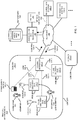
- FIG. 1 is an example diagram illustrating association management and fluid delivery management in a medical environment according to embodiments herein.
- medical environment 100 includes network 190 (which may include a packet-switched network, the Internet, WiFi TM network, etc.), association management resource 140, information system 165, domain 150-1, domain 150-2, etc.
- network 190 which may include a packet-switched network, the Internet, WiFi TM network, etc.
- association management resource 140 information system 165
- domain 150-1 domain 150-2, etc.
- Each of the domains 150 in medical environment 100 can represent a location in medical environment 100 in which fluid is delivered to a corresponding recipient.
- a fluid delivery domain can represent a hospital room, a person's home, etc.
- caregiver 106 configures fluid delivery system 125-1 (such as first pump) to deliver fluid from source 120-1 to recipient 108.
- fluid delivery system 125-2 such as a second pump
- Recipient 108 in this example is patient John Smith.
- domain 150-1 further includes communication interface 145-1.
- each of the medical devices in domain 150-1 has the ability to communicate with communication interface 145-1.
- each of the fluid delivery systems 125 is communicatively coupled to communication interface 145-1 via a respective communication link (such as a wired communication link, wireless communication link etc.).
- communication link 128-1 supports communications between fluid delivery system 125-1 and communication interface 145-1;
- communication link 128-2 supports communications between fluid delivery system 125-2 and communication interface 145-1;
- communication link 128-3 supports communications between fluid delivery system 125-3 and communication interface 145-1;
- communication link 128-4 supports communications between management device 160-1 and communication interface 145-1; and so on.
- Each of the communication links 128 can be a hardwired or wireless link.
- any suitable protocol can be employed to communicate RF and/or hardwired communications between each of the devices and communication interface 145-1 over a respective communication link.
- each of the communication links 128 supports communications in accordance with the WiFi TM protocol.
- communication interface 145-1 supports communications 126-1 through network 190 to any of one or more remotely located resources such as association management resource 140, information system 165, etc.
- communication interface 145-1 receives communications 126-2 from the one or more remotely located resources in network 190.
- Communication interface 145-1 forwards the received communications 126-2 to the appropriate resource (such as a medical device) in domain 150-1.
- each of the one or more resources such as fluid delivery system 125-1, fluid delivery system 125-2, fluid delivery system 125-3 (such as third fluid pump), management device 160-1, etc., is able to communicate with any of one or more resources located in medical environment 100 through communication interface 145-1 and over network 190.
- each of the devices or systems in medical environment 100 is assigned a corresponding unique network address.
- each of the devices or systems in the medical environment is able to communicate with a respective remotely located resource.
- any of the medical devices located in medical environment 100 are able to transmit the generated data packets to association management resource 140.
- the association management resource 140 can include a network address of a corresponding target medical device in generated data packets to forward such communications to the target medical device.
- the resources in medical environment 100 communicate amongst each other via a HyperText Transfer Protocol (HTTP) type protocol.
- HTTP HyperText Transfer Protocol
- the resources can communicate via using secure HTTP (i.e., HTTPS), ensuring that communications and the connections between the association management resource 140 and the fluid delivery systems are secure and that messages are fully encrypted.
- association management resource 140 collects information (such as medical information 122) associated with different resources in the medical environment 100 from one or more resources.
- the association management resource 140 manages associations.
- the association management resource 140 based on received data, the association management resource 140 produces and manages association information 185 stored in repository 180.
- association information 185 managed by association management resource 140 keeps track of associations amongst the different entities in medical environment 100.
- each of the entities in the medical environment 100 is assigned a corresponding unique value.
- caregiver 106 is assigned to the unique value CGVR 106; fluid delivery system 125-1 is assigned the unique value FDD 313; fluid delivery system 125-2 is assigned a unique value FDD 432; fluid delivery system 125-3 is assigned the unique value FDD 566; domain 150-1 in medical environment 100 is assigned the unique value LOC 277; domain 150-2 in medical environment 100 is assigned a unique value LOC 278; and so on.
- Each of the domains 150 in medical environment 100 can include similar resources as domain 150-1.
- association management resource 140 produces and manages association information 185 to keep track of associations between the different resources or entities in medical environment 100.
- association management resource 140 can receive communications from any resource in medical environment 100 (such as information system 165, domain 150-1, domain 150-2, etc.) indicating to create one or more new associations.
- the association management resource 140 can receive communications indicating to terminate one or more associations.
- the state of association information 185 stored in repository 180 changes over time.
- the association management resource 140 can be configured to implement a set of association rules 142 to manage respective associations between entities in medical environment 100.
- these rules 142 help automate the association and disassociation of entities.
- a rule may state that when two medical devices are associated, they also share the same patient and location associations.
- the rules 142 can specify how to create associations.
- Association rules 142 may be defined for the entire institution (medical environment 100) or may be domain or device type specific. This enable rules for an intensive care unit to differ from rules used in an operating room. Use of different rules would also allow, for example, association rules between two infusion pumps to differ from those between an infusion pump and a patient monitor.
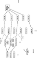
- FIG. 2 is an example diagram illustrating association information according to embodiments herein.
- the association information 185-1 indicates associations (as represented by a line) between different types of entities in the medical environment 100.
- Each node in FIG. 2 represents a corresponding entity or resource in or associated with medical environment 100.
- association management resource 140 can employ any suitable resource such as pointers, tables, mappings, etc., can be used to indicate the associations amongst the different entities.
- association management resource 140 is configured to constantly search network 194 for information related to entities located in medical environment 100.
- the association management resource 140 receives medical information 122-1 from information system 165-1; the association management resource receives medical information 122-2 from information system 165-2; and so on.
- Medical information 122 can be any suitable type of information.
- the medical information can be patient information, billing information, physician information, medication order information (such as one or more prescription drug orders), caregiver information, location information, etc.
- association management resource 140 Based on information received from one or more resources in medical environment 100, the association management resource 140 creates association information 185-1 to indicate current associations amongst different entities or resources located in medical environment 100.
- medical environment 100 is not limited to a corresponding location such as a hospital. Medical environment 100 can include any resource, entity, etc., that is related to patient care.
- association information 185-1 indicates that: caregiver CGVR 106 (caregiver 106) has been assigned to care for patients Jane Doe and John Smith; caregiver CGVR 188 is not assigned to care for anyone; and so on.
- associations in the association information 185 can indicate assignments.
- association information 185-1 indicates that: fluid-based drug RX29 has been prescribed to Jane Doe; fluid-based drugs RX24 and RX36 have been prescribed to John Smith; and so on.
- the association management resource 140 can be configured to receive association information from any suitable resource.
- the association management resource 140 receives medical information 122-1 from information system 165-1 indicating that a physician has prescribed fluid-based drugs RX24 and RX36 to John Smith. Based on receipt of this medical information (medication order information), the association management resource 140 creates the association lines between medication order drugs RX24 and RX36 and John Smith.
- association information 185-1 indicates that: patient Jane Doe resides in a respective domain LOC 299 (such as a first hospital room); patient John Smith resides in domain LOC 277 (such as a second hospital room); patient James Henry resides in domain LOC 267 (such as a third hospital room); and so on.
- association information 185-1 indicates that: the domain assigned LOC 299 is located on the second floor of building 345; the domain assigned LOC 277 is located on the second floor of building 345; the domain assigned LOC 267 is located on the second floor of building 345; the domain assigned LOC 269 is located on the second floor of building 345; the domain assigned LOC 269 is located on the second floor of building 345; and so on.
- association information 185 certain associations in the association information 185 are static. That is, location LOC 299 (such as a first room in a hospital) will always reside in the second floor of building 345; location LOC 277 (such as a second room in a hospital) will always reside in the second floor building 345; location LOC 267 (such as a third room in a hospital) will always reside in the second floor building 345; and so on.
- caregiver CGVR106 may be temporarily assigned to care for John Smith and Jane Doe during a first shift.
- the caregiver CGVR188 may be assigned to care for Jane Doe and John Smith instead of caregiver CGVR106.
- the association management resource 140 in response to detecting this change, the association management resource 140 would create a respective association between caregiver CGVR188 and each patient Jane Doe and John Smith. Additionally, the association management resource 140 may terminate an association between caregiver CGVR106 and Jane Doe and John Smith.
- the respective pump-patient association lines, association information 185-1 indicates that: the fluid delivery system assigned the unique value FDD 983 has been assigned for use by Jane Doe.
- the association management resource 140 In response to detecting that a caregiver such as caregiver CGVR106 currently dispenses medication order RX 29 prescribed to Jane Doe using the fluid pump FDD 983, the association management resource 140 produces an association line between the medication order RX29 and the fluid delivery system FDD 983.
- the association line between the prescribed drug RX29 and fluid delivery system FDD 983 indicates that the fluid delivery system FDD 983 is being used or has been assigned to deliver the prescribed drug RX 29 to patient Jane Doe.
- association information 185-1 it is possible to identify the status of fluid deliveries as well as assignments of different medical devices to different patients.
- the associations enable one to identify different types of information associated with medical care. For example, via the associations in association information 185-1 presented in FIG. 2 , the corresponding user is able to identify that caregiver CGVR106 has been assigned to care for patient Jane Doe and that caregiver CGVR106 has configured pump FDD 983 to deliver medication order RX29 to Jane Doe.
- association management resource 140 creates associations between the different entities as specified by association information 185 based on input.
- the association management resource 140 can be a computer server running on a local area network.
- the association management resource 140 is capable of communicating with medical devices/information systems connected either directly or wirelessly to that network 190.
- the server exposes one or more communication services. These services utilize one or more communication mechanisms.
- one service may be capable of communicating using RESTful web services while another, performing the same function, may support SOAP based web services.
- Each communication service is capable supporting one or more functions, including but not limited to, registering, modifying and/or unregistering clinical associations and returning association details to those that request that information.
- association information 185 can be configured to maintain a history of associations made over time such that it is possible to view prior existing associations between entities at a given snapshot in time.
- the association management resource 140 produces the association information 185 to keep track of the history of the associations made over time. The retrieval of the history information from association information 185 stored in repository 180, a respective user is able to keep track the occurrence of different types of events.
- All maintained associations can be made available to medical devices or any component capable of interacting through the server communication services.
- association management resource 140 has not receiving information indicating that fluid delivery system 125-1, fluid delivery system 125-2, and fluid delivery system 125-3 reside in domain 150-1 (LOC 277).
- each of the fluid delivery systems can be configured to occasionally or periodically broadcast information indicating the presence at a particular location.
- a nearby communication interface at the location (such as communication interface 145-1) may receive the communication and forward the location information to association management resource 140.
- the association management resource 140 can create an association between each of the fluid delivery systems and a corresponding location in which the fluid delivery system resides.
- a caregiver may be required to operate a corresponding fluid delivery system to create a new association between the fluid delivery system and a location in which the fluid delivery system resides.
- association of a respective medical device (such as a fluid delivery system) can be automated or required that a caregiver manually associated a respective fluid delivery system with a location.
- caregiver 106 (assigned the unique value CGVR106) receives notification that the medication orders RX24 and RX25 need to be administered to recipient 108.
- the notification can be received on any suitable medical device.
- the caregiver 106 receives the notification on medical device 160-1 assigned to and operated by the caregiver 106.
- the caregiver 106 initiates communications with association management resource 140. For example, the caregiver 106 inputs association information to association management resource 140 to indicate the fluid delivery system 125-1 and fluid delivery system 125-2 are being assigned to John Smith.
- Supplying the association information to association management resource 140 can be achieved in any suitable manner.
- the caregiver 106 provides the input (association information) associating the fluid delivery system 125-1 to John Smith through a graphical user interface of fluid delivery system 125-1.
- the fluid delivery system 125-1 In response to receiving the input, the fluid delivery system 125-1 communicates the pump-patient association information over communication link 128-1 to communication interface 145-1. Communication interface 145-1 further communicates the input over network 190 to association management resource 140.
- the association management resource 140 receives the input generated by the caregiver 106 and updates the corresponding association information 185-2 as shown in FIG. 3 to indicate that the fluid delivery system 125-1 (FDD 313) has been assigned for use by recipient 108 (John Smith). In this example embodiment, as shown in FIG.
- the association management resource 140 in response to receiving the input notification from the caregiver 106 (CGVR 106) that the fluid delivery system 125-1 (FDD 313) has been assigned for use by recipient 108 (John Smith), the association management resource 140 creates a new patient-pump association 310-1 between recipient 108 (John Smith) and fluid delivery system 125-1 (FDD 313).
- the caregiver 106 operates in graphical user interface of fluid delivery system 125-2.
- the caregiver 106 (CGVR 106) provides the input (association information) associating the fluid delivery system 125-2 to John Smith through fluid delivery system 125-2 (FDD 432).
- the fluid delivery system 125-2 (FDD 432) communicates this new pump-patient association information over communication link 128-2 to communication interface 145-1.
- Communication interface 145-1 further communicates the input over network 190 to association management resource 140.
- the association management resource 140 receives the input generated by the caregiver 106 and updates the corresponding association information 185-2 as shown in FIG. 3 .
- the association management resource 140 in response to receiving the input notification from the caregiver 106 that the fluid delivery system 125-2 (FDD 432) has been assigned for use by recipient 108 (John Smith), the association management resource 140 creates a new patient-pump association 310-2 between recipient 108 (John Smith) and fluid delivery system 125-2 (FDD 313).
- the notification generated by caregiver 106 indicating assignment of the fluid delivery system 125-1 (FDD 313) for use by recipient 108 (John Smith) can be submitted from any suitable resource.
- the respective caregiver 106 can operate a respective graphical user interface of a corresponding fluid delivery system to communicate the association information to association management resource 140.
- the caregiver 106 can operate a graphical user interface of management device 160-1 to input the association information to association management resource 140.
- the management device 160-1 transmits the association information received from the caregiver 106 over communication link 128-4 to communication interface 145-1.
- Communication interface 145-1 communicates the association information through network 190 to association management resource 140.
- the association management resource 140 utilizes the received information to create the association between the patient John Smith and the one or more fluid delivery systems.
- embodiments herein can include creating an association between a medical device and a corresponding entity such as a patient in the medical environment 100.
- Creating the associations 310-1 and 310-2 between the fluid delivery systems and the patient is useful because it enables a corresponding caregiver 106 to more efficiently operate the fluid delivery systems assigned to recipient 108 (John Smith).
- the operator (caregiver 106) of the fluid delivery systems can initiate a search for information associated with the recipient 108 (John Smith) to obtain useful information.
- the caregiver 106 provides input to a corresponding graphical user interface of the fluid delivery system 125-1 to transmit a request for information associated with an entity such as recipient 108 from fluid delivery system 125-1 over the network 190 to the association management resource 140.
- the association management resource 140 searches a repository for medical information associated with the entity to which the fluid delivery system has been assigned.
- flow delivery system 125-1 has been assigned to recipient 108 (John Smith).
- the caregiver 106 may be interested and retrieving information regarding prescribed drugs prescribed to recipient 108 (John Smith).
- the query from the caregiver 106 to association management resource 140 would indicate that the caregiver 106 would like information about one or more different drugs prescribed to the corresponding recipient 108 (John Smith).
- the association management resource 140 accesses association information 185 shown in FIG. 3 to identify that John Smith has been assigned use of fluid delivery system 125-1 (FDD 313) and fluid delivery system 125-2 (FDD 432) by caregiver 106. Additionally, via the association information 185, the association management resource 140 identifies that medication orders RX24 and RX36 both have been assigned to recipient 108 (John Smith). In one embodiment, the association management resource 140 initiates retrieval of medical information (such as medication order information) associated with medication orders RX24 and RX36 from repository 180 or other suitable resource.
- medical information such as medication order information
- medication order information associated with a respective medication order can be stored as one or more retrievable objects for retrieval and viewing by the respective caregiver.
- the medication order information in a respective retrievable object can indicate parameters such as a type of fluid were type of drug to be delivered to the corresponding patient, a rate at which the fluid will be delivered to the corresponding patient, a time when the fluid should be dispensed to the corresponding patient, etc.
- association management resource 140 initiates transmission of the medical information over the network 190 to fluid delivery system 125-1.
- fluid delivery system 125-1 initiates display of the medical information associated with medication orders RX 24 and/or RX 36 on a respective graphical user interface displayed on a display screen of fluid delivery system 125-1 for viewing by caregiver 106.
- association of the fluid delivery system to a corresponding patient enables the caregiver to easily retrieve information (such as medication order information) associated with the corresponding patient.
- association of the fluid delivery systems to a corresponding patient is shown by way of non-limiting example.
- embodiments herein can include use of a medical device to create any suitable types of associations.
- further embodiments herein can include associating a fluid delivery system (fluid pump) with any suitable entity such as a location, one or more other medical devices, another fluid pump, a caregiver, etc.
- a fluid delivery system fluid pump
- any suitable entity such as a location, one or more other medical devices, another fluid pump, a caregiver, etc.
- FIG. 4 is an example diagram illustrating creation of associations amongst different entities in a medical environment according to embodiments herein.
- association information 185-3 does not yet indicate an association between John Smith and corresponding domain 150-1 (LOC 277).
- association management resource 140 receives notification that John Smith has been moved into domain 150-1.
- the association management resource 140 updates the association information 185-3 in FIG. 4 to include association 410 to indicate that the patient John Smith now resides in domain 150-1 (LOC 277).
- the notification that the recipient 108 has been moved into domain 150-1 can be received from any suitable resource.
- the caregiver 106 can operate management device 160-1 to notify association management resource 140 that the recipient 108 now resides in domain 150-1.
- information system 165 can be configured to keep track of the location of each of the patients in the medical environment 100.
- the information system 165 can be configured to forward the location information (medical information) associated with the recipient 108 to the association management resource 140.
- association management resource 140 receives input from each of the fluid delivery systems 125 indicating their location.
- the association information 185-3 managed by association management resource 140 indicates that: fluid delivery system 125-1 (FDD 313) is available and associated with domain 150-1 (LOC 277); fluid delivery system 125-2 (FDD 432) is available and associated with domain 150-1 (LOC 277); fluid delivery system 125-3 (FDD 566) is available and associated with domain 150-1 (LOC 277), and so on. Because the fluid delivery systems 125-1, 125-2, and 125-3 are not currently assigned for use by a particular patient, the association information 185-3 indicates that such fluid delivery systems are available.
- the association management resource 140 can be configured to maintain status information associated with each of the entities as well.
- the caregiver 106 operates fluid delivery system 125-1 (FDD 313) to transmit association information to association management resource 140.
- the fluid delivery system 125-1 transmits the association information (associating the fluid delivery system 125-1 to recipient 108) over communication link 128-1 to communication interface 145-1.
- Communication interface 145-1 further communicates the association information generated by caregiver 106 (or other suitable resource) to association management resource 140.
- the association management resource 140 updates the association information 185-4 as shown in FIG. 5 to indicate the new association 510-1 between the fluid delivery system 125-1 (FDD 313) to recipient 108 (John Smith). That is, the new association 510-1 indicates that the fluid delivery system 125-1 (FDD 313) has been assigned for use by recipient 108 (John Smith).
- the caregiver 106 operates fluid delivery system 125-2 (FDD 432) to transmit association information to association management resource 140.
- the fluid delivery system 125-2 transmits the association information (associating the fluid delivery system 125-2 to recipient 108) over communication link 128-2 to communication interface 145-1.
- Communication interface 145-1 further communicates the association information generated by caregiver 106 to association management resource 140.
- the association management resource 140 updates the association information 185-4 in FIG. 5 to indicate the new association 510-2 between the fluid delivery system 125-1 (FDD 313) and recipient 108 (John Smith).
- association of the fluid delivery systems with one or more entities in the medical environment 100 makes it easy for the caregiver 106 or other user to retrieve information associated with the interconnected entities.
- association information 185 can include status information associated with the respective entity.
- association information 185 includes node representing John Smith.
- the node representing John Smith can include an object such as one or more files or documents associated with John Smith.
- the information in the object associated with John Smith can indicate information such as an age of the patient, gender of the patient, medical history, nature of an injury, allergies, etc.
- the object assigned to John Smith can include any useful information that would be helpful for providing care to John Smith while he resides in medical environment 100.
- the node associated with a respective caregiver can indicate useful information such as a name of the caregiver, the current location of the caregiver, the title of the caregiver such as whether the caregiver is a nurse or doctor, contact information of the caregiver, etc.
- the fluid delivery systems can be used to retrieve useful information.
- a user in domain 150-1 can provide commands to a corresponding graphical user interface of fluid delivery system 125-1 to retrieve and display useful information on a respective display screen of the fluid delivery system 125-1.
- the user of the fluid delivery system 125-1 generates a command to retrieve personal information associated with the recipient 108 (John Smith) to which the fluid delivery system 125-1 has been assigned.
- the user initiates transmission of the command to the association management resource 140 to retrieve the personal information about recipient 108 (John Smith).
- the association management resource 140 retrieves the object assigned to the node John Smith in the association information 185 and forwards it to the fluid delivery system 125-1 for display on a corresponding display screen.
- the associations make it possible to retrieve useful information associated with the recipient 108.
- FIG. 6 is an example diagram illustrating creation of associations between different entities in a medical environment according to embodiments herein.
- the caregiver 106 operates management device 160-1 and generates query 620 to learn of the availability of fluid delivery systems on floor two of building 345.
- the caregiver 106 forwards the query to association management resource 140.
- the association management resource 140 In response to receiving the query 620, the association management resource 140 analyzes association information 185-5 and identifies that fluid delivery system 125-1 (FDD 313), fluid delivery system 125-2 (FDD 432), and fluid delivery system 125-3 (FDD 566) are all located in a nearby room (LOC 269) with respect to domain 150-1 (LOC 277).
- the association management resource 140 transmits this information for display on management device 160-1 for viewing by caregiver 106. Based on such information, indicating that available fluid delivery systems are located at location LOC 269, the caregiver 106 walks to the hospital room (LOC 269) to move fluid delivery system 125-1 (FDD 313) and fluid delivery system 125-2 (FDD 432) into domain 150-1.
- LOC 269 the hospital room
- FDD 313 fluid delivery system 125-1
- FDD 432 fluid delivery system 125-2
- the association management resource 140 can receive updates indicating that the fluid delivery systems have been moved into domain 150-1 (LOC 277).
- the association management resource 140 updates association information 185-6, creating an association between the fluid delivery system 125-1 (FDD 313) and domain 150-1 (LOC 277); the association management resource 140 creates an association between the fluid delivery system 125-to (FDD 432) and domain 150-1 (LOC 277).
- the association management resource 140 can be configured to maintain the status of these fluid delivery systems as being available because they have not yet been assigned to a corresponding patient.
- association management resource 140 indicating that fluid delivery system 125-1 and fluid delivery system 125-2 have been assigned for use by recipient 108 (John Smith).
- the association management resource 140 creates new association 710-1 to indicate that the fluid delivery system 125-1 (FDD 313) has been assigned for use by recipient 108 (John Smith); the association management resource 140 creates new association 710-2 to indicate that the fluid delivery system 125-2 (FDD 432) has been assigned for use by recipient 108 (John Smith).
- the respective fluid delivery system and or other management device can be used to retrieve useful information associated with the interrelated entities.
- FIG. 8 is an example diagram illustrating proximity association according to embodiments herein.
- Conventional medical devices typically operate independently and autonomously from one another even when those devices are connected to the same patient. As part of the setup of each device, a clinician or caregiver identifies both the location of the device and the patient association. In the event that multiple medical devices exist at a bedside, the same, time consuming association process must be performed with each device in order to associate the medical device with the other devices or patient. In other words, conventional methods require that the caregiver operate each of the devices independently to associate that device with a particular patient or other entity.
- devices such as fluid delivery systems 125, medical device 160-1, etc. may associate with a device designated as a master device, form a group and inherit the location and patient associations of that master device. This significantly reduces the overall setup time of each subsequent device and reduces the probability of error during that process. As further discussed below, creation of a group of medical devices can be achieved in any suitable manner.
- Proximity association as described herein enables medical devices to form associations with one another through a few simple user interactions.
- a wireless communication such as Bluetooth, Near Field Communication (RFC), RFID or similar near distance RF technology, etc.
- a medical device such as a fluid delivery system (master device) can be configured to transmit an invitation to nearby devices to join it in a group. Any available devices within range of this master device respond to the transmission, giving users and devices the option to join the group. For those that accept the invitation to join the group, an association is created between the two devices and the associated patient and location of the master device are synchronized with those joining the group.
- RFID Near Field Communication
- a personal area or piconet network is formed between the devices and the patient and location associations maintained by the master device is synchronized with each new group member.
- proximity association can include a system made up of one or more medical devices 825 and association management resource 140 (such as a clinical association server).
- each of the medical devices 825 can be configured to include a wireless transceiver (transmitter and receiver).
- medical device 825-1 includes a transceiver to communicate with any other medical devices in medical environment 800;
- medical device 825-2 includes a transceiver to communicate with any other medical devices in medical environment 800;
- medical device 825-3 includes a transceiver to communicate with any other medical devices in medical environment 800;
- medical device 825-4 includes a transceiver to communicate with any other medical devices in medical environment 800;
- medical device 825-5 includes a transceiver to communicate with any other medical devices in medical environment 800; and so on.
- a user may initiate the formation of a new group.
- the device from which an operator such as a caregiver initiates formation of the new group is referred to herein as the master device.
- the master device transmits a broadcast message to other medical devices located in the medical environment 800.
- the broadcast message is transmitted as an RF signal within domain 150-1.
- the medical device 825-1 can be configured to communicate with the association management resource 140 to identify nearby medical devices.
- the association management resource 140 can be configured to communicate over network 190 and communication interface 145-1 to medical devices 825-2, 825-3, 825-4, etc., in domain 150-1 to indicate that the caregiver 106 might to create the new grouping.
- the other non-master medical devices in domain 150-1 can receive the invitation to join the new grouping in a number of different ways.
- the medical devices in domain 150-1 can receive a communication directly from the master medical device 825-1 or receive notification from the association management resource 140.
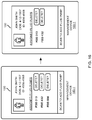
- Any medical device that receives the invitation and is available can join the group. For example, when a device receives the invitation message generated by master medical device 825-1, the medical device receiving the invitation message prompts the user (via a respective notification on a display screen of the receiving device) to acknowledge or reject the group invitation on its local user interface for viewing by a caregiver.
- the display screen of medical device 825-2 displays a message that a nearby master medical device 825-1 generated a corresponding invitation to join a group;
- the display screen of medical device 825-3 displays a message that a nearby master medical device 825-1 generated a corresponding invitation to join a group;
- the display screen of medical device 825-4 displays a message that a nearby master medical device 825-1 generated a corresponding invitation to join a group; and so on.
- the visual prompt displayed on each of the medical devices receiving the broadcast message from medical device 825-1 indicates that medical device 825-1 has initiated formation of a medical device grouping.
- the visual prompt can indicate patient and location information associated with a particular patient for which the association is being created. Display of the visual prompt on each of the medical devices receiving the broadcast message gives the caregiver the option to join the group.
- medical device 825-1 More specifically, assume that the caregiver would like medical device 825-1, medical device 825-6, and medical device 825-2, to be part of the grouping. Because the medical device 825-1 initiated the broadcast message inviting other medical devices to possibly join the group, medical device 825-1 is already part of the new grouping.
- the operator (such as caregiver 106) in domain 150-1 provides input to the graphical user interface displayed on display screen of medical device 825-6 indicating that medical device 825-6 has joined the new grouping.
- the operator provides input to the graphical user interface displayed on display screen of medical device 825-2 indicating that medical device 825-2 has joined the new grouping.
- the respective medical device in response to receiving input that the operator would like a respective medical device included in the new grouping, transmits a message to the other medical devices or association management resource 140 indicating that it has joined the new grouping.
- Each of the medical devices can be configured to display a listing of the current members of the new grouping.
- the user reviews the members of the group from any device in the group and can optionally remove itself or other members from the group.
- a device When a device joins a group, it connects to a local network such as piconet network of the master device. It then inherits the patient and location associated with the master medical device 825-1. Thus, if the master medical device 825-1 has been associated with recipient 108 (John Smith), then each of the medical devices 825-6 and 825-2 become associated with the recipient 108 (John Smith).
- the devices can be configured to notify association management resource 140 of its association with the group and its associated patient and location information.
- the association management resource 140 creates and stores the associations amongst the medical devices and the new grouping.
- the association information is stored centrally and available to other devices in the system via the association management resource 140.
- FIG. 9 is an example diagram of a flowchart illustrating formation of a group and creation of associations amongst one or more medical devices according to embodiments herein.
- the caregiver 106 optionally associates the master medical device 825-1 with corresponding location and/or patient information.
- the caregiver 106 operates the master medical device 825-1 to form a new grouping.
- the master medical device 825-1 forms a new grouping, shares his location and patient association information and broadcast a corresponding invitation to other potential members.
- the medical device 825-1 (such as a first fluid delivery system) or association management resource 140 initiates communication with a set of one or more medical devices located in a vicinity of the medical device 825-1 (first fluid delivery system).
- each of the medical devices that receive the invitation initiates display of a query on a corresponding display screen of a medical device asking the user whether or not the device should be included in the new grouping.
- each of the medical devices activates a prompt indicating that the respective medical device displaying the prompt can be programmed to join a group including the fluid delivery system.
- the caregiver provides input to each of the medical devices that are to be included in the new grouping.
- the medical devices that accept the invitation to join the group assume the associations of the group members.
- the caregiver 106 optionally reviews the new grouping and removes any medical devices that were incorrectly added to the new grouping.
- the caregiver 106 can operate fluid delivery system 125-1 in order to learn of other fluid delivery systems located in a corresponding vicinity.
- association management resource 140 transmits a response to fluid delivery system 125-1 indicating that fluid delivery system 125-2 and fluid delivery system 125-3 are also located within domain 150-1 based on the association information 185.
- the association management resource 140 can provide notification to an operator (caregiver 106) of the fluid delivery system 125-1 that fluid delivery system 125-2 and fluid delivery system 125-3 are available in a vicinity of the fluid delivery system 125-1.
- the caregiver 106 can select delivery system 125-2 and fluid delivery system 125-3 in order to form a respective grouping.
- the fluid delivery system 125-1 communicates a request to form this new grouping to association management resource 140.
- the request indicates that the fluid delivery system 125-1 would like to form a group including fluid delivery system 125-1 and fluid delivery system 125-2.
- the association management resource 140 In response to receiving the request to form the new grouping, the association management resource 140 associates the fluid delivery system 125-1 and fluid delivery system 125-2. The association management resource 140 records the association between the fluid delivery system 125-1 and the fluid delivery system 125-2.
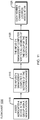
- FIG. 10 is an example diagram illustrating a patient association according to embodiments herein.
- embodiments herein include creating an association between a selected patient and each medical device in the new grouping at a time when the selected patient is assigned for the first time to any of the medical devices in the newly formed grouping.
- a notification will be sent via wide area wireless technology, such as WiFi TM , to the other devices in the group, indicating that the association now exists. This gives the user the option of accepting it or opting out of the group.
- processing block 1010 the user associates a device in the group with a new patient.
- a respective medical device determines whether a patient association already exists with a particular medical device. If so, processing continues at processing block 1020. If not processing continues at processing block 1025.
- processing block 1020 in response to detecting that the corresponding medical device is already associated with a patient, the medical device removes itself from the grouping and produces a corresponding notification.
- processing block 1025 in response to detecting that the corresponding medical device is currently not associated with a particular patient, and that the user associates the corresponding medical device with a new patient, the corresponding medical device associates itself with the news patient.
- the corresponding medical device notifies other medical devices in the group of the association with the new patient.
- each of the medical devices in the grouping that receives the notification of the association between the corresponding medical device and new patient updates their association to the new patient as well.
- each of the other medical devices in the grouping updates their association with the new patient as well.
- FIG. 11 is an example diagram illustrating location association according to embodiments herein.
- the newly established grouping of medical devices may not be associated with a particular location.
- this association will be set the first time any device in that group forms a respective association with location.
- a notification is sent by the association management resource 140 via a wide area wireless technology, such as Wi-Fi TM , to each medical device in the group.
- Wi-Fi TM wide area wireless technology
- a group's location association can be changed at any time. Doing so will result in a notification being sent by the association management resource 140 via a wide area wireless technology, such as Wi-Fi TM , to each device in the group and cause each device to update its location.
- a wide area wireless technology such as Wi-Fi TM
- the caregiver 106 or other suitable resource associates a given medical device in the new grouping with a new location.
- the caregiver 106 operates the given medical device to associate the given medical device with the new location.
- the given medical device notifies all members of the newly formed group of the location change.
- each medical device in the grouping changes its location association to the location as indicated by the association management resource 140.
- association of one of the medical devices in the grouping to a corresponding location causes each of the other members in the grouping to be associated with the corresponding location.
- one embodiment herein includes transmitting appropriate information to the association management resource 140 to indicate the creation of the new associations.
- the device when the caregiver 106 exits the group formation utility on the master device, the device ceases to transmit and all devices disconnect. However, their association with the group remains intact.
- each of the medical devices can be configured to provide the ability to disassociate itself with the respective group it has joined.
- a device will also automatically be removed from a group if a user attempts to form a new group from that device or associates the device with a different patient.
- FIG. 21 is an example diagram illustrating associations amongst resources according to embodiments herein. Note that each of the medical devices 825 as previously discussed in FIG. 8 can be a fluid delivery system.
- the medical device 825-1 (FDD 314), medical device 825-6 (FDD 433), and medical device 825-2 (FDD 567) are currently available for use. That is, they are not associated with any patient.
- caregiver 106 creates a respective grouping in any of the manners as discussed above.
- the caregiver 106 can operate medical device 825-1 (FDD 314) as a master device to initiate creation of a corresponding grouping.
- the association management resource 140 creates a new association 850-1 to indicate the association between the medical device 825-1 (FDD 314) and medical device 825-6 (FDD 433).
- association management resource 140 in response to learning that medical device 825-2 is also to be included in the group, association management resource 140 also creates association 850-2 to indicate that medical device 825-2 is part of the grouping. For example, the association management resource 140 creates new association 850-2 to indicate the association between medical device 825-6 (FDD 433) and medical device 825-2 (FDD 567).
- association 850-1 and association 850-2 in association information 185-22 it is known that medical device 825-1 (FDD 314), medical device 825-6 (FDD 433), and medical device 825-2 (FDD 567) are all part of the same grouping.
- the association management resource 140 can receive further input from the corresponding caregiver 106 indicating to associate the grouping of medical devices (FDD 314, FDD 433, and FDD 567) with a corresponding patient's such as John Smith. In response to receiving such input, the association management resource 140 updates the association information 185-23 as shown in FIG. 23 to indicate that the new grouping of medical devices has been associated with recipient 108 (John Smith).
- association management resource 140 receives notification that medical device 825-1 (FDD 314) has been assigned by the caregiver 106 to John Smith, the association management resource 140 creates an association between each of the medical devices in the grouping and John Smith as shown.
- the association management resource 140 can receive input from the caregiver 106 to associate this new grouping with a corresponding location. Assume that the caregiver 106 associates the new grouping of medical devices with domain 150-1 (LOC 277). In response to receiving such input, the association management resource 140 updates the association information 185-24 as shown in FIG. 24 to indicate that the grouping of medical devices has been associated with domain 150-1 (LOC 277).
- association management resource 140 receives notification that medical device 825-1 (FDD 314) has been assigned by the caregiver 106 to domain 150-1 (LOC 277), the association management resource 140 creates an association between each of the medical devices in the grouping and domain 150-1 (LOC 277).
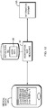
- FIG. 12 is an example diagram illustrating census-based association according to embodiments herein.
- Embodiments herein include a way to provide a medical device 1260 (such as management device 160-1, fluid delivery system 125-1, would delivery system 125-2, etc.) with knowledge of admission, discharge, and transfer information can help facilitate this association process.
- a medical device 1260 such as management device 160-1, fluid delivery system 125-1, would delivery system 125-2, etc.
- FIG. 13 is an example diagram illustrating census-based association according to embodiments herein.
- the association management resource can be configured to receive location information associated with one or more entities in the medical environment 100.
- the association management resource 140 collects location data indicating where each of multiple patients resides in the medical environment 100.
- the association management resource 140 then stores the associations (such as location data) in repository 180.
- each of the associations associates a respective patient with a corresponding location in the medical environment in which the respective patient resides.
- association information 185-1 indicates that John Smith resides that location LOC 277 (such as domain 150-1), Jane Doe resides at location LOC 299, James Henry resides at location LOC 267, etc.
- the association management resource 140 receives messages from information system 165.
- the information system 165 can include a healthcare enterprise system that generates messages indicating a location of different entities.
- the association management resource 140 receives ADT messages from the information system 165.
- the association management resource 140 extracts patient identification information, location information, demographic information, etc., from the messages received from information system 165.
- the association management resource 140 stores the received patient information in repository 180 as association information 185.
- processing block 1325 in a manner as previously discussed, assume that a corresponding medical device 1260 is aware of its current location.
- the medical device forwards the location information (i.e., it's current location) to association manager resource 140.
- the corresponding user operates a respective medical device 1260 such as a fluid delivery system, management device 160-1, etc., to initiate association of the medical device 1260 with a corresponding patient.
- a respective medical device 1260 such as a fluid delivery system, management device 160-1, etc.
- the user requests to associate the medical device 1260 with a corresponding patient. This can include providing input command to the medical device 1260.
- the medical device 1260 transmits a communication to association manager resource 140 to learn of the patients that are within a vicinity of the current location of the medical device 1260.
- association management resource 140 receives input indicating that the current location of the medical device 1260 is in a vicinity of floor 2, building 345. Based on association information 185-1 in FIG. 2 , the association manager resource 140 detects that Jane Doe, John Smith, and James Henry are present within a vicinity of the medical device. The association manager resource 140 generates a list including these names (i.e., identities of patients) and forwards the list of identities of the patients to the medical device 1260.
- the medical device 1260 receives the listing of names including Jane Doe, John Smith, and James Henry.
- the medical device 1260 initiates display of the listing of these names on a respective display screen of the medical device 1260 to indicate patients that were side in a vicinity of the current location of the medical device 1260.
- the user of the medical device 1260 selects a particular patient (such as John Smith) from the list to associate the medical device 1260 with the particular patient.
- a particular patient such as John Smith
- the medical device 1260 communicates the selection of the particular patient John Smith from the list to association management resource 140.
- the association management resource 140 then creates a new association between the medical device 1260 and the particular patient John Smith.
- the operator of the medical device 1260 can generate a query to association management resource 140 to learn of different medication orders that have been assigned to a particular patient John Smith.
- the caregiver 106 operating the medical device 1260 initiates transmission of a communication from the medical device 1260 to the association management resource 140 to learn of any medication order drugs that have been assigned for delivery to John Smith.
- the association management resource 140 receives the inquiry as transmitted over the network 190 from an operator of the medical device 1260 to association management resource 140. As mentioned, the inquiry requests medication order drug information assigned to the particular patient John Smith.
- the association management resource 140 searches the association information 185 stored in repository 180 for the medication order drug information assigned to the particular patient John Smith.
- the association management resource 140 transmits the medication order drug information (associated with RX24 and RX36) over the network 190 to the operator of the medical device.
- the medical device 1260 initiates display of the medication order drug information on a display screen of the medical device for viewing by the respective caregiver 106.
- the operator of the medical device 1260 can obtain other types of information associated with the corresponding patient such as a doctor that has been assigned to the patient, the history of medical information associated with the patient, etc.
- FIG. 14 is an example diagram illustrating use of a management device to manage medical care according to embodiments herein.
- Mobile devices ranging from laptops to cell phones are increasingly becoming the primary productivity tool of care providers throughout the healthcare enterprise.
- the same devices (such as management device 160-1) therefore become the ideal host for software applications enabling care providers to associate themselves with their patients and associate their patients with connected medical devices.
- the management device 160-1 can be any suitable type of computing device such as a smartphone, scanner, PDA, tablet computer, laptop computer, etc.
- management device 160-1 is disparately located with respect to fluid delivery systems or other medical devices located in the medical environment 100.
- the caregiver 106 stores the management device 160-1 in their pocket when moving from one location to another.
- Management device 160-1 executes management application 1440. Execution of management application 1440 enables the caregiver to define or create associations as part of their normal care workflow.
- the management application 1440 can be configured to perform any suitable type of operations such as receiving input from a corresponding caregiver 106 operating the management device 160-1, providing notifications to the corresponding caregiver 106, communicating with association management resource 140, and so on.
- the caregiver 106 can operate management device 160-1 in order to associate itself with a corresponding patient.
- the management device 160-1 can be configured to transmit its corresponding location information to association management resource 140.
- association management resource 140 forwards the listing of patients in a nearby vicinity of the management device 160-1 to management device 160-1 for display on display screen 130.
- the caregiver 106 can provide input indicating which of the patients the caregiver 106 is going to provide care.
- Another way of associating a particular caregiver to a patient is to scan a corresponding barcode 1420 associated with the patient. For example, assume that caregiver 106 has already created an association with Jane Doe and Sidney Green indicating that the caregiver 106 will be providing care to these patients.
- the caregiver 106 can operate the management device and scan the barcode 1420 associated with John Smith to add John Smith as a patient cared for by caregiver 106. In response to scanning the barcode 1420, the management device 160-1 adds John Smith to the displayed list of patients that are cared for by the corresponding caregiver 106.
- the application 1440 in response to scanning of the barcode 1420, transmits an identity of the scanned patient to association management resource 140.
- the association management resource 140 updates the association information 185 to indicate that the caregiver 106 is now assigned to provide care to patient John Smith.
- updating of the association information 185 can include creating an association between caregiver 106 (CGVR106) and John Smith.
- the caregiver 160-1 can operate the management device 160-1 to determine which patients are assigned to the caregiver 106. For example, the caregiver 106 can generate a message from management device 160-1 to association management resource 140 to learn of any patients that are assigned to the caregiver 106. The association management resource 140 transmits the list to management device 160-1 for display to caregiver 106.
- the association management resource 140 can be configured to: receive a communication transmitted over the network 190 from the management device 160-1 (mobile device) operated by the caregiver 106, the communication requesting a listing of patients assigned to the caregiver; analyze the association information 185 identifying a set of patients assigned to the caregiver; and in response to receiving the second communication, transmit a reply message over the network 190 to the management device 160-1 operated by the caregiver 106, the reply message indicating the set of patients assigned to the caregiver 106.
- FIG. 15 is an example diagram illustrating use of a caregiver's management device to associate one or more fluid delivery systems with a corresponding patient according to embodiments herein.
- the caregiver 106 can operate the management device 160-1 to identify any medical devices that have been assigned to the corresponding patient John Smith.
- the caregiver 106 can operate management device 160-1 to communicate over network 190 with the association management resource 140 and retrieve a listing of any medical devices (such as fluid pumps) that have been assigned to the corresponding patient John Smith.
- the patient John Smith can be selected from the display screen 130 in FIG. 14 listing patients Jane Doe, Sidney Green, and John Smith.
- the association management resource 140 receives the communication transmitted over the network 190 from the management device 160-1 operated by the caregiver 106.
- the communication indicates selection of a particular patient such as John Smith.
- the association management resource 140 transmits a message over the network 190 to the management device 160-1 operated by the caregiver 160-1.
- the reply message from the association management resource 140 includes a listing of medical devices such as fluid delivery systems assigned to the particular patient John Smith.
- association management resource 140 indicates that fluid delivery system 125-1 (FDD 313) and fluid delivery system 125-2 (FDD 432) both have been assigned for use by John Smith.
- the management device 160-1 initiates display of the different fluid pumps assigned for use by John Smith.
- the caregiver 106 operating management device 160-1 can be configured to scan barcode 1520 located on the fluid delivery system 125-3. Scanning of the barcode 1520 indicates that the caregiver 106 like to add the fluid delivery system 125-3 (FDD 566) for use by John Smith. The management device 160-1 communicates this information to association management resource 140.
- the management device 160-1 In response to assigning the fluid delivery system 125-3 to the patient John Smith, the management device 160-1 initiates display of the identity of the fluid delivery system 125-3 (FDD 566) on the corresponding display screen 130 of management device 160-1 to indicate that the fluid delivery system 125-3 is now assigned for use by John Smith.
- FDD 566 the identity of the fluid delivery system 125-3
- FIG. 16 is an example diagram illustrating use of a caregiver operated management device to dissociate a fluid delivery system with a corresponding patient according to embodiments herein.
- the management device 160-1 displays the different fluid delivery systems that have been assigned for use by John Smith.
- fluid delivery system 125-1 FDD 313)
- fluid delivery system 125-2 FDD 432
- fluid delivery system 125-3 FDD 566
- association management resource 140 In response to receiving selection of delete symbol 1620 displayed on display screen 130 of management device 160-1, management device 160-1 communicates with association management resource 140 to delete a respective association between delivery system 125-3 (FDD 566) and John Smith.
- Association management resource 140 receives the communication and updates the association information 185 to indicate that the association between fluid delivery system 125-3 (FDD 566) and John Smith has been terminated.
- the association management resource 140 communicates the termination of the association to management device 160-1.
- the management device 160-1 updates its corresponding display screen to indicate that only fluid delivery system 125-1 (FDD 313) and fluid delivery system 125-2 (FDD 432) are assigned for use by patient John Smith.
- FIG. 17 is an example diagram illustrating use of association information to facilitate delivery of multiple fluid-based drugs to a patient using multiple fluid delivery systems according to embodiments herein.
- medical devices that are involved in the delivery of a medication benefit from having access to the order for that medication over network 190.
- the patient's order (such as a object specifying parameters of delivering a medication order) may be forwarded from association management resource 140 over network 190 to the respective medical device that is assigned to deliver the medication order fluid to a corresponding recipient.
- the following states illustrate settings of corresponding fluid delivery systems during the process of assigning different fluid-based drugs by a particular fluid delivery system.
- the process of receiving input from the different fluid delivery systems and display of corresponding notification information makes it easier for a corresponding caregiver to safely administer different drugs from multiple fluid pumps.
- the caregiver 106 operates the fluid delivery system 125-1 to identify medication order medication assigned for delivery to patient John Smith.
- the caregiver 106 operates fluid delivery device 125-1 to transmit a query to association management resource 140 to learn of medication order medication prescribed to patient John Smith.
- the query from the caregiver 106 includes a request for a listing of medicine prescribed to the patient John Smith.
- the association management resource 140 searches the association information 185 and repository 180 for medication orders assigned to John Smith. Association management resource 140 analyzes the association information 185 and determines that medication order RX 24 and RX 36 have been assigned to John Smith. The association management resource 140 transmits a message (including medical information) to fluid delivery system 125-1. The medical information in the message received by fluid delivery system 125-1 indicates that John Smith has been assigned medication order drugs RX 24 and RX 36.
- Fluid delivery system 125-1 initiates display of a notification on display screen 130-1 of fluid delivery system 125-1 that both RX 24 and RX36 are to be administered to patient John Smith. Assume in this example that the caregiver 106 operating the fluid delivery system 125-1 selects medication order RX 24 for delivery by fluid delivery system 125-1. Selection of medication order RX 24 can include touching a display of a symbol RX24 on the display screen of fluid delivery system 125-1.
- the fluid delivery system 125-1 in response to receiving selection of the symbol RX24 on the display screen of the fluid delivery system 125-1, transmits a message to association management resource 140 to indicate that the fluid delivery system 125-1 has been selected to deliver the medication order RX24 to patient John Smith.
- the association management resource 140 creates a new association between fluid delivery system 125-1 (FDD 313) and node RX 24 in association information 185 to indicate that the medication order RX 24 is being administered by the fluid delivery system 125-1.
- the fluid delivery system 125-1 In response to receiving input indicating that fluid delivery system 125-1 has been selected to deliver medication order RX 24 to the patient John Smith, the fluid delivery system 125-1 presents a notification on a respective display screen of fluid delivery system 125-1 that medication order RX 24 has been assigned for delivery by fluid delivery system 125-1. If desired, as shown, the display screen 130-1 of fluid delivery system 125-1 can further indicate that medication order RX 36 is still outstanding. For example, the message "NON YET ADMINISTERED" or other visual indicator implies that medication order RX 36 has not yet been assigned for delivery by a particular fluid delivery system.
- Further embodiments herein can include providing notification to fluid delivery system 125-2 that the corresponding medication order RX 24 is being delivered to the recipient 108 (John Smith) via fluid delivery system 125-1 (FDD 313).
- the fluid delivery system 125-2 receives notification from association management resource 140 or other suitable resource that the fluid delivery system 125-1 has been assigned to administer the medication order RX 24 to patient John Smith.
- the fluid delivery system 125-2 initiates display of a message on display screen 130-2 indicating that the medication order RX24 is being delivered on remote fluid delivery system 125-1 (FDD 313).
- the caregiver 106 is able to determine that the medication order RX 36 has not vet been assigned for delivery by a respective fluid pump.
- the carrier 106 provides input to fluid delivery system 125-2 indicating selection of medication order RX36 for delivery to the patient via fluid delivery system 125-2.
- the caregiver 106 touches the symbol labeled RX36 on display screen fluid delivery system 125-2 in order to assign delivery system 125-2 for delivery of the medication order RX 36.
- the fluid delivery system 125-2 communicates with the association management resource 140.
- the association management resource 140 creates an association between medication order RX 36 and the fluid delivery system 125-2 (FDD 432) to indicate that fluid delivery system 125-2 has been configured to deliver the medication order RX 36. Accordingly, via this newly created association, association management resource 140 tracks that the fluid delivery system 125-2 has been assigned to deliver medication order RX 36.
- the fluid delivery system 125-2 In response to the assignment of delivering medication order RX 36 on fluid delivery system 125-2, the fluid delivery system 125-2 updates its corresponding display screen 130-2 to indicate that medication order RX 36 has been assigned for delivery on fluid delivery system 125-2.
- Fluid delivery system 125-1 can be configured to receive the notification from any suitable resource such as from fluid delivery system 125-2 or from association management resource 140 to update display screen 130-1.
- Further embodiments herein can include receiving feedback from each of the fluid delivery systems indicating a status of delivering a corresponding medication order.
- the fluid delivery system 125-1 can be configured to continuously communicate status information back to association management resource 140 regarding progress of delivering the medication order RX24 to patient John Smith.
- the fluid delivery system 125-2 can be configured to continuously communicate status information back to association management resource 140 regarding progress of delivering the medication order RX36 to patient John Smith.
- Feedback from a respective fluid delivery system can include information such as a time when the medication order is administered, amounts of the medication order that have not yet been delivered to a corresponding patient, etc.
- the caregiver 106 operates the medical device 160-1 to retrieve the status information associated with delivery of the medication order drugs from association management to resource 140. Accordingly, from a remote location, the carrier 106 can monitor attributes of the fluid delivery systems 125-1 and 125-2.
- FIG. 18 is an example diagram illustrating authentication and authorization of a user of a fluid delivery system according to embodiments herein.
- Information system 165 can include technology such as Microsoft's Active Directory, to manage user accounts (which include details on a user's credentials), roles, permissions, etc.
- information system 165 includes an enterprise user management system.
- the association management resource 140 (clinical association server) is capable of interacting with an enterprise user management system and using that system to authenticate and authorize a user attempting to log into one of its connected medical devices.
- the medical device operated by a respective caregiver is capable of interacting directly with an enterprise user management system and using that system to authenticate and authorize a user attempting to log into itself.
- fluid delivery system 125-1 initiates a challenge to a caregiver 106 operating the fluid delivery system to provide appropriate authentication information (such as username and password information) to operate the fluid delivery system 125-1.
- appropriate authentication information such as username and password information
- the fluid delivery system 125-1 transmits the login request (such as username and password information) S inputted by the caregiver 106 to association management resource 140.
- Association management resource 140 forwards the login request to information system 165 (such as an enterprise user management system).
- the information system 165 receives (such as login request) over the network 190 from the caregiver 106.
- the login requests can include authentication information (such as username and password) to operate fluid delivery system 125-1.
- the information system 165 or other suitable resource verifies the authentication information received from the fluid delivery system 125-1.
- the information system 165 transmits a login response (such as a command) to association management resource 140.
- the association management resource 140 forwards the login response to fluid delivery system 125-1.
- the login response (such as a command) enables (e.g., unlocks) the fluid delivery system 125-1, enabling the caregiver to perform operations as discussed herein such as deliver fluid to a patient using the fluid delivery system 125-1.
- the caregiver 106 can further communicate with association management resource 140 in order to associate the fluid delivery system 125-1 to the caregiver 106.
- the caregiver 106 can provide input specifying an identity of the caregiver 106 to the association management resource 140.
- the association management resource 140 modifies association information 185 to create an association between the caregiver 106 and the fluid delivery system 125-1.
- medical device fluid delivery system 125-1
- the user can be authenticated without having to communicate over network 190 with a remote resource such as information system 165 or association management resource 140.
- medical device such as fluid system 125-1
- all data generated by a respective fluid delivery system can be tagged with an identity of the caregiver 106. This information is optionally routed to the caregiver 106 for display on medical device 160-1.
- FIG. 19 is an example block diagram of a computer device for implementing any of the operations as discussed herein according to embodiments herein.
- fluid delivery system 100 includes a computer system 750 to execute association management resource 140, management application 1440, etc.
- computer system 750 of the present example includes an interconnect 711, a processor 713 (such as one or more processor devices, computer processor hardware, etc.), computer readable storage medium 712 (such as hardware storage to store data), I/O interface 714, and communications interface 717.
- processor 713 such as one or more processor devices, computer processor hardware, etc.
- computer readable storage medium 712 such as hardware storage to store data
- I/O interface 714 I/O interface 714
- communications interface 717 communications interface 717.
- Interconnect 711 provides connectivity amongst processor 713, computer readable storage media 712, I/O interface 714, and communication interface 717.
- I/O interface 714 provides connectivity to a repository 780 and, if present, other devices such as a playback device, display screen, input resource 792, a computer mouse, etc.
- Computer readable storage medium 712 (such as a non-transitory hardware medium) can be any hardware storage resource or device such as memory, optical storage, hard drive, rotating disk, etc. In one embodiment, the computer readable storage medium 712 stores instructions executed by processor 713.
- Communications interface 717 enables the computer system 750 and processor 713 to communicate over a resource such as network 190 to retrieve information from remote sources and communicate with other computers.
- I/O interface 714 enables processor 713 to retrieve stored information from repository 180.
- controller application 140-1 e.g., software, firmware, etc.
- Controller application 140-1 can be configured to include instructions to implement any of the operations as discussed herein.
- processor 713 accesses computer readable storage media 712 via the use of interconnect 711 in order to launch, run, execute, interpret or otherwise perform the instructions in association management application 140-1 stored on computer readable storage medium 712.
- association management application 140-1 produces processing functionality such as association management process 140-2 in processor 713.
- association management process 140-2 associated with processor 713 represents one or more aspects of executing association management application 140-1 within or upon the processor 713 in the computer system 750.
- the computer system 750 can include other processes and/or software and hardware components, such as an operating system that controls allocation and use of hardware resources to execute association management application 140-1.
- computer system may be any of various types of devices, including, but not limited to, a wireless access point, a mobile computer, a personal computer system, a wireless device, base station, phone device, desktop computer, laptop, notebook, netbook computer, mainframe computer system, handheld computer, workstation, network computer, application server, storage device, a consumer electronics device such as a camera, camcorder, set top box, mobile device, video game console, handheld video game device, a peripheral device such as a switch, modem, router, or in general any type of computing or electronic device.
- the computer system 850 resides in fluid delivery system 100. However, note that computer system 850 may reside at any location or can be included in any suitable resource in network environment 100 to implement functionality as discussed herein.
- FIG. 20 is a flowchart 2000 illustrating an example method according to embodiments. Note that there will be some overlap with respect to concepts as discussed above.
- the association management resource 140 receives input over a network 190.
- the input associates fluid delivery system 125-1 to an entity located in a medical environment 100 in which the fluid delivery system 125-1 is operated.
- the association management resource 140 records an association between the fluid delivery system 125-1 and the entity as indicated by the received input.
- the association management resource 140 initiates transmission of medical information associated with the entity over the network to fluid delivery system 125-1.
- An algorithm as described herein, and generally, is considered to be a self-consistent sequence of operations or similar processing leading to a desired result.
- operations or processing involve physical manipulation of physical quantities.
- quantities may take the form of electrical or magnetic signals capable of being stored, transferred, combined, compared or otherwise manipulated. It has been convenient at times, principally for reasons of common usage, to refer to such signals as bits, data, values, elements, symbols, characters, terms, numbers, numerals or the like. It should be understood, however, that all of these and similar terms are to be associated with appropriate physical quantities and are merely convenient labels.
Description
- Conventional infusion pumps enable a caregiver to intravenously deliver fluid to a patient. A process of delivering fluid-based drugs requires multiple operations. For example, a physician must first generate a medication order specifying one or more fluid-based drugs for delivery to a particular patient in a hospital. Typically, a pharmacy in the hospital receives the medication order supplied by the physician. In accordance with the medication order, the pharmacy dispenses a corresponding physical order by providing the drugs to a caregiver for delivery to a respective patient.
- In certain instances, the medication order includes multiple fluid-based drugs that need to be administered intravenously to the respective patient. In such an instance, and assuming that each of the fluid-based drugs must be delivered by a separate fluid delivery system (fluid pump), the caregiver overseeing the patient must locate multiple fluid delivery systems (fluid pumps) in the hospital. This itself may be a difficult task because the hospital may not keep good track of unused medical equipment.
- Subsequent to locating the fluid delivery systems, the caregiver must transport the fluid delivery systems to a site where the patient resides. After the patient's bedside, in accordance with the medication order information, the caregiver operates the one or more fluid delivery systems to intravenously deliver the corresponding prescribed fluid-based drugs to the patient. Each fluid pump must be individually programmed by the caregiver to intravenously dispense the fluid to the patient.
-
US 2012/075061 A1 shows a system and method of associating a plurality of objects. A physical space is defined and a real-time locating system (RTLS) is used to determine objects that are within the physical space. -
US 2010/0287006 A1 shows methods of providing data feeds from medical devices associated with patients to computing devices associated with clinicians. A computing device for each of a number of clinicians is registered as being associated with the clinician. - Conventional techniques of intravenously delivering fluid to a patient suffer from deficiencies. For example, operations of managing delivery of one or more fluids to a patient is tedious and can result in fluid delivery errors.
- As a specific example, assume that a caregiver is required to administer infusion of two different types of prescribed fluids to a corresponding patient. First, as mentioned, the caregiver must retrieve two fluid delivery systems - one to deliver each of the prescribed fluid-based medicines. Thereafter, each of the fluid delivery systems has to be configured for programmed to deliver one of the multiple prescribed fluids.
- In certain instances, to learn more about the different drugs that have been prescribed to the patient, and view specific details of how to administer the drugs, the caregiver has to log onto a remote computer separate from the fluid pump. The remote computer is typically at least several feet away from the actual fluid pump that is being configured to deliver the prescribed fluids to the patient. In a case of administering multiple fluids to a patient, this means that, in order to fulfill delivery of a respective medication order, the caregiver has to provide inputs to at least three different devices including a remote computer, a first fluid pump, and a second fluid pump. Thus, the caregiver must provide input to three different user interfaces, none of which may be aware of each other. The caregiver must be trained how to use each of the user interfaces - the user interface on the fluid pump and the user interface of the remote computer.
- Failure to properly deliver the prescribed fluid-based drugs to a corresponding patient may be harmful, or possibly fatal. In contrast to conventional techniques, embodiments herein include unique ways of managing fluid delivery systems and related data, facilitating delivery of fluid to a recipient.
- According to embodiments herein, entities in a clinical environment such as medical devices and patients can have many associations. These include, but are not limited to, associations amongst patients, locations, medical orders such as medication orders, programmed settings, care providers, medical devices, etc. Identifying associations amongst different entities allows software-based medical systems to perform more intelligently, enabling caregivers to provide a higher level of care. This could range from providing a simplified device setup process to providing smart advisories back to clinicians based on its knowledge of the collective operation of all associated devices.
- One embodiment herein includes an association management resource (such as a Clinical Association Server). The association management resource allows medical devices and information systems to both register associations and utilize association mappings to identify relevant information associated with a medical task such as administering a fluid to a patient.
- Embodiments herein can include a server capable of accepting, managing, and providing any number of associations between a medical device and other entities within the healthcare enterprise. Entities with which associations can be made include, but are not limited to, patients, locations, medical orders, programmed settings, care providers, other medical devices, etc.
- In one non-limiting example embodiment, the association management resource exposes communication services that can be called remotely by a medical device/information system to register its own associations or to retrieve the associations of other clinical entities. In accordance with more specific embodiments, the association management resource server may optionally be configured with a set of association rules. Rules can be configured to define the impact of one association upon another, causing associations or disassociations to automatically occur as a result of the setting or resetting of others.
- In accordance with yet more specific embodiments, an association management resource (such as a server resource and storage resource) receives input over a network. The input can be received from any suitable resource such as from a medical device such as a fluid delivery system that will be used to deliver fluid to a recipient. The input associates a fluid delivery system (medical device) such as a fluid pump to an entity located in a medical environment in which the fluid delivery system is operated.
- Based on input received over the network, the association management resource records an association between the fluid delivery system and the entity as indicated by the received input.
- The association management resource can be configured to create a different type of association depending upon the type associated with the entity. For example, if the entity is a patient, in response to receiving the input, the association management resource creates a patient-pump association between the patient and the corresponding fluid delivery system. If the entity is a location, in response to receiving input, the association management resource creates a pump-location association between the pump and the corresponding location where the pump resides. If the entity is another fluid pump, response to receiving input, the association management resource creates a pump-pump association between the first fluid pump and the second fluid pump. Accordingly, in this manner, the association management resource can create different types of associations.
- Creating the association between the fluid delivery system and the entity is useful because it enables a corresponding caregiver to more efficiently operate the respective medical device such as a fluid delivery system. For example, subsequent to making an association between the entity and the fluid delivery system, the operator of the fluid delivery system can initiate a search for information associated with the entity via communications over a respective network with the association management resource.
- For further sake of illustration, after creating a corresponding association, assume that the operator of the fluid delivery system transmits a request (such as a search query) for information associated with the entity over the network to the association management resource. In response to receiving the request, the association management resource searches a repository for medical information associated with the entity. Subsequent to retrieval, the association management resource initiates transmission of the medical information over the network to an operator of the fluid delivery system.
- Accordingly, an operator of a respective fluid delivery system can associate a fluid delivery system (a medical device such as a fluid pump) with a particular entity such as a patient, location, one or more other medical devices, the caregiver, etc. Thereafter, the operator of the fluid delivery system is able to better manage use of the fluid delivery system based on relevant medical information, which is accessible as a result of the association.
- In one embodiment, in addition to receiving input from a corresponding medical device such as a fluid pump, the association management resource gathers and stores information associated with the entity prior to the operator providing the input associating the fluid delivery system with the entity. For example, the association management resource can be configured to communicate with one or more systems in a hospital environment to retrieve information about a particular entity. In such an instance, even before a respective caregiver creates an association between the medical device and a corresponding entity, the association management resource already has information about the corresponding entity. Even before receiving input associating a particular medical device with an entity, the association management resource may have already created associations between the entity and other related entities.
- As an example, the entity may be a patient in the hospital. Prior to receiving a request to associate a respective medical device (such as a pump) to the patient, the association management resource may already have collected data from one or more resources in a respective medical environment indicating that the patient is assigned to or resides in a corresponding room in a hospital. Creating a new association between the medical device and the patient indirectly associates medical device with a corresponding room in which the patient resides.
- In one embodiment, after an operator of the fluid delivery system creates an association between the fluid delivery system and the entity, the medical information associated with the entity is immediately available to the fluid delivery system and/or corresponding operator of the fluid delivery system.
- As another example, prior to receiving the input indicating to create a new association between a medical device (such as a fluid pump) and a corresponding entity such as a patient, association information produced by the association management resource the association management resource can indicate that the patient has been prescribed one or more fluid drugs. After creating the new association between the medical device and the patient, an operator of the medical device is able to access the association management resource to identify information related to the patient such as the prescribed one or more fluid drugs.
- Note that the input from an operator of the fluid delivery system (medical device) can be received from any suitable resource. For example, in accordance with one embodiment, the fluid delivery system can include a display screen configured to display a graphical user interface. Additionally, via software instructions executing in the fluid delivery system, the fluid delivery system can be configured to communicate with the association management resource over a corresponding network connection. The operator of the fluid delivery system provides input to the graphical user interface of the medical device to associate the medical device with a particular entity. The medical device forwards the association request over the respective network connection to the association management resource.
- As mentioned, subsequent to creating a corresponding association between the fluid delivery system and a respective entity, the operator of the fluid delivery system can use the graphical user interface to perform a search query to obtain medical information associated with the entity over the network connection. As previously discussed, in response to receiving a search query from the fluid delivery system, the association management resource retrieves and transmits appropriate medical information to the fluid delivery system.
- In accordance with yet further embodiments, note that the operator of the fluid delivery system does not necessarily need to use a graphical user interface physically located on the fluid delivery system in order to perform tasks such as associate the fluid delivery system to a corresponding patient, retrieve medical information, etc. For example, an operator of the fluid delivery system (such as a caregiver that uses the fluid delivery system to deliver a corresponding fluid-based drug to a patient) may be assigned a management device to facilitate giving care to one or more patients. The management device can be a handheld management device that is disparately located with respect to the fluid delivery system operated to deliver fluid to a corresponding patient.
- In certain embodiments, the operator of the fluid delivery system can initiate creation of an association between a medical device and another entity via input to a corresponding display screen on the handheld management device. Thus, an association between a fluid delivery system and a respective entity can be achieved in a number of different ways depending on the embodiment.
- These and other more specific embodiments are disclosed in more detail below.
- Note that any of the resources as discussed herein can include one or more computerized devices, fluid delivery systems, servers, base stations, wireless communication equipment, communication management systems, workstations, handheld or laptop computers, or the like to carry out and/or support any or all of the method operations disclosed herein. In other words, one or more computerized devices or processors can be programmed and/or configured to operate as explained herein to carry out different embodiments of the invention.
- Yet other embodiments herein include software programs to perform the steps and operations summarized above and disclosed in detail below. One such embodiment comprises a computer program product including a non-transitory computer-readable storage medium (i.e., any physical computer readable hardware storage medium) on which software instructions are encoded for subsequent execution. The instructions, when executed in a computerized device (e.g., computer processing hardware) having a processor, program and/or cause the processor to perform the operations disclosed herein. Such arrangements are typically provided as software, code, instructions, and/or other data (e.g., data structures) arranged or encoded on a non-transitory computer readable storage medium such as an optical medium (e.g., CD-ROM), floppy disk, hard disk, memory stick, etc., or other a medium such as firmware or shortcode in one or more ROM, RAM, PROM, etc., or as an Application Specific Integrated Circuit (ASIC), etc. The software or firmware or other such configurations can be installed onto a computerized device to cause the computerized device to perform the techniques explained herein.
- Accordingly, embodiments herein are directed to a method, system, computer program product, etc., that supports operations as discussed herein.
- One embodiment herein includes a computer readable storage medium and/or system having instructions stored thereon. The instructions, when executed by computer processor hardware, cause the computer processor hardware to: receive input over a network, the input associating a fluid delivery system to an entity located in a medical environment in which the fluid delivery system is operated; record an association between the fluid delivery system and the entity as indicated by the received input; search a repository for medical information associated with the entity; and initiate transmission of the medical information over the network to an operator of the fluid delivery system..
- The ordering of the operations above has been added for clarity sake. Note that any of the processing steps as discussed herein can be performed in any suitable order.
- Other embodiments of the present disclosure include software programs and/or respective hardware to perform any of the method embodiment steps and operations summarized above and disclosed in detail below.
- It is to be understood that the system, method, apparatus, instructions on computer readable storage media, etc., as discussed herein also can be embodied strictly as a software program, firmware, as a hybrid of software, hardware and/or firmware, or as hardware alone such as within a processor, or within an operating system or within a software application.
- As discussed herein, techniques herein are well suited for managing and facilitating use of medical devices. However, it should be noted that embodiments herein are not limited to use in such applications and that the techniques discussed herein are well suited for other applications as well.
- Additionally, note that although each of the different features, techniques, configurations, etc., herein may be discussed in different places of this disclosure, it is intended, where suitable, that each of the concepts can optionally be executed independently of each other or in combination with each other. Accordingly, the one or more present inventions as described herein can be embodied and viewed in many different ways.
- Also, note that this preliminary discussion of embodiments herein purposefully does not specify every embodiment and/or incrementally novel aspect of the present disclosure or claimed invention(s). Instead, this brief description only presents general embodiments and corresponding points of novelty over conventional techniques. For additional details and/or possible perspectives (permutations) of the invention(s), the reader is directed to the Detailed Description section and corresponding figures of the present disclosure as further discussed below.
-
-
FIG. 1 is an example diagram illustrating association management in a medical environment according to embodiments herein. -
FIG. 2 is an example diagram illustrating management of associations amongst different entities in a medical environment according to embodiments herein. -
FIG. 3 is an example diagram illustrating association of a medical device to an entity in a medical environment according to embodiments herein. -
FIG. 4 is an example diagram illustrating management of associations amongst different entities in a medical environment according to embodiments herein. -
FIG. 5 is an example diagram illustrating association of a medical device to an entity according to embodiments herein. -
FIG. 6 is an example diagram illustrating management of associations amongst different entities in a medical environment according to embodiments herein. -
FIG. 7 is an example diagram illustrating association of an entity to a medical device according to embodiments herein. -
FIG. 8 is an example diagram illustrating proximity association according to embodiments herein. -
FIG. 9 is an example diagram of a method illustrating formation of a medical device grouping and creation of associations amongst one or more medical devices according to embodiments herein. -
FIG. 10 is an example diagram of a method illustrating association of a group of medical devices to a corresponding patient according to embodiments herein. -
FIG. 11 is an example diagram of a method illustrating association of a group of medical devices to a corresponding location according to embodiments herein. -
FIG. 12 is an example diagram illustrating census-based association according to embodiments herein. -
FIG. 13 is an example diagram of a method illustrating census-based association according to embodiments herein. -
FIG. 14 is an example diagram illustrating use of a management device to associate patients to a particular caregiver according to embodiments herein. -
FIG. 15 is an example diagram illustrating use of a caregiver's management device to associate one or more medical devices with a corresponding patient according to embodiments herein. -
FIG. 16 is an example diagram illustrating use of a caregiver operated management device to dissociate a medical device from a corresponding patient according to embodiments herein. -
FIG. 17 is an example diagram illustrating use of association information to facilitate delivery of multiple fluid-based drugs to a patient using multiple fluid delivery systems according to embodiments herein. -
FIG. 18 is an example diagram illustrating authentication and authorization of a user of a medical device according to embodiments herein. -
FIG. 19 is a diagram illustrating an example computer architecture in which to execute any of the functionality according to embodiments herein. -
FIG. 20 is an example diagram illustrating a method facilitating association of a medical device to a corresponding entity according to embodiments herein. -
FIG. 21 is an example diagram illustrating association management according to embodiments herein. -
FIG. 22 is an example diagram illustrating creation of assns to indicate a grouping of medical devices according to embodiments herein. -
FIG. 23 is an example diagram illustrating association of a grouping of medical devices to a respective patient according to embodiments herein. -
FIG. 24 is an example diagram illustrating association of a grouping of medical devices to a location according to embodiments herein. - The foregoing and other objects, features, and advantages of the invention will be apparent from the following more particular description of preferred embodiments herein, as illustrated in the accompanying drawings in which like reference characters refer to the same parts throughout the different views. The drawings are not necessarily to scale, with emphasis instead being placed upon illustrating the embodiments, principles, concepts, etc.
- Now, more specifically,
FIG. 1 is an example diagram illustrating association management and fluid delivery management in a medical environment according to embodiments herein. - As shown,
medical environment 100 includes network 190 (which may include a packet-switched network, the Internet, WiFi™ network, etc.),association management resource 140,information system 165, domain 150-1, domain 150-2, etc. - Each of the domains 150 (e.g., domain 150-1, domain 150-2, etc.) in
medical environment 100 can represent a location inmedical environment 100 in which fluid is delivered to a corresponding recipient. A fluid delivery domain can represent a hospital room, a person's home, etc. - In this non-limiting example embodiment, assume that
caregiver 106 configures fluid delivery system 125-1 (such as first pump) to deliver fluid from source 120-1 torecipient 108. Assume math thecaregiver 106 configures fluid delivery system 125-2 (such as a second pump) to deliver fluid from source 120-2 torecipient 108.Recipient 108 in this example is patient John Smith. - Note that domain 150-1 further includes communication interface 145-1. In one embodiment, each of the medical devices in domain 150-1 has the ability to communicate with communication interface 145-1. In this example embodiment, each of the
fluid delivery systems 125 is communicatively coupled to communication interface 145-1 via a respective communication link (such as a wired communication link, wireless communication link etc.). - In this non-limiting example embodiment, communication link 128-1 supports communications between fluid delivery system 125-1 and communication interface 145-1; communication link 128-2 supports communications between fluid delivery system 125-2 and communication interface 145-1; communication link 128-3 supports communications between fluid delivery system 125-3 and communication interface 145-1; communication link 128-4 supports communications between management device 160-1 and communication interface 145-1; and so on.
- Each of the communication links 128 can be a hardwired or wireless link.
- Any suitable protocol can be employed to communicate RF and/or hardwired communications between each of the devices and communication interface 145-1 over a respective communication link. In one embodiment, each of the communication links 128 supports communications in accordance with the WiFi™ protocol.
- As further shown, communication interface 145-1 supports communications 126-1 through
network 190 to any of one or more remotely located resources such asassociation management resource 140,information system 165, etc. - In a reverse direction, communication interface 145-1 receives communications 126-2 from the one or more remotely located resources in
network 190. Communication interface 145-1 forwards the received communications 126-2 to the appropriate resource (such as a medical device) in domain 150-1. - Accordingly, each of the one or more resources such as fluid delivery system 125-1, fluid delivery system 125-2, fluid delivery system 125-3 (such as third fluid pump), management device 160-1, etc., is able to communicate with any of one or more resources located in
medical environment 100 through communication interface 145-1 and overnetwork 190. - In one embodiment, each of the devices or systems in
medical environment 100 is assigned a corresponding unique network address. Via client-server type communications, each of the devices or systems in the medical environment is able to communicate with a respective remotely located resource. For example, using a network address of theassociation management resource 140 in respective generated data packets, any of the medical devices located inmedical environment 100 are able to transmit the generated data packets toassociation management resource 140. In a reverse direction, theassociation management resource 140 can include a network address of a corresponding target medical device in generated data packets to forward such communications to the target medical device. - In one non-limiting example embodiment, the resources in medical environment 100 (such as each of the
fluid delivery systems 125, management device 160-1,association management resource 140, etc.) communicate amongst each other via a HyperText Transfer Protocol (HTTP) type protocol. By way of non-limiting example, the resources can communicate via using secure HTTP (i.e., HTTPS), ensuring that communications and the connections between theassociation management resource 140 and the fluid delivery systems are secure and that messages are fully encrypted. - As shown, and as previously discussed, embodiments herein include an
association management resource 140. In accordance with one embodiment, and along the other functions, theassociation management resource 140 collects information (such as medical information 122) associated with different resources in themedical environment 100 from one or more resources. - As its name suggests, the
association management resource 140 manages associations. By way of non-limiting example, based on received data, theassociation management resource 140 produces and managesassociation information 185 stored inrepository 180. - As its name suggests, the
association information 185 managed byassociation management resource 140 keeps track of associations amongst the different entities inmedical environment 100. - In accordance with yet further embodiments, each of the entities in the
medical environment 100 is assigned a corresponding unique value. - For sake of illustration, assume that
caregiver 106 is assigned to theunique value CGVR 106; fluid delivery system 125-1 is assigned theunique value FDD 313; fluid delivery system 125-2 is assigned aunique value FDD 432; fluid delivery system 125-3 is assigned theunique value FDD 566; domain 150-1 inmedical environment 100 is assigned theunique value LOC 277; domain 150-2 inmedical environment 100 is assigned aunique value LOC 278; and so on. - Each of the domains 150 in
medical environment 100 can include similar resources as domain 150-1. - As further discussed below,
association management resource 140 produces and managesassociation information 185 to keep track of associations between the different resources or entities inmedical environment 100. - Note that associations can change over time. For example, the
association management resource 140 can receive communications from any resource in medical environment 100 (such asinformation system 165, domain 150-1, domain 150-2, etc.) indicating to create one or more new associations. - Additionally, in addition to receiving communications to create new associations, the
association management resource 140 can receive communications indicating to terminate one or more associations. Thus, the state ofassociation information 185 stored inrepository 180 changes over time. - By further way of a non-limiting example, the
association management resource 140 can be configured to implement a set of association rules 142 to manage respective associations between entities inmedical environment 100. In one embodiment, theserules 142 help automate the association and disassociation of entities. For example, a rule may state that when two medical devices are associated, they also share the same patient and location associations. Thus, therules 142 can specify how to create associations. - Association rules 142 may be defined for the entire institution (medical environment 100) or may be domain or device type specific. This enable rules for an intensive care unit to differ from rules used in an operating room. Use of different rules would also allow, for example, association rules between two infusion pumps to differ from those between an infusion pump and a patient monitor.
-
FIG. 2 is an example diagram illustrating association information according to embodiments herein. As shown in this example, the association information 185-1 indicates associations (as represented by a line) between different types of entities in themedical environment 100. Each node inFIG. 2 represents a corresponding entity or resource in or associated withmedical environment 100. - Further note that management of the associations amongst the different entities can be achieved in any number of ways. For example, the
association management resource 140 can employ any suitable resource such as pointers, tables, mappings, etc., can be used to indicate the associations amongst the different entities. - Associations can be created continuously over time. For example, in one embodiment,
association management resource 140 is configured to constantly search network 194 for information related to entities located inmedical environment 100. In the example embodiment shown, theassociation management resource 140 receives medical information 122-1 from information system 165-1; the association management resource receives medical information 122-2 from information system 165-2; and so on. -
Medical information 122 can be any suitable type of information. For example, the medical information can be patient information, billing information, physician information, medication order information (such as one or more prescription drug orders), caregiver information, location information, etc. - Recall that each of the entities in
medical environment 100 is assigned a unique value. Based on information received from one or more resources inmedical environment 100, theassociation management resource 140 creates association information 185-1 to indicate current associations amongst different entities or resources located inmedical environment 100. - Note that
medical environment 100 is not limited to a corresponding location such as a hospital.Medical environment 100 can include any resource, entity, etc., that is related to patient care. - In this example, via respective caregiver-patient association lines in
FIG. 2 , association information 185-1 indicates that: caregiver CGVR 106 (caregiver 106) has been assigned to care for patients Jane Doe and John Smith;caregiver CGVR 188 is not assigned to care for anyone; and so on. Thus, associations in theassociation information 185 can indicate assignments. - Further in this example, via respective medicine-patient association lines, association information 185-1 indicates that: fluid-based drug RX29 has been prescribed to Jane Doe; fluid-based drugs RX24 and RX36 have been prescribed to John Smith; and so on.
- As previously discussed, the
association management resource 140 can be configured to receive association information from any suitable resource. In one embodiment, theassociation management resource 140 receives medical information 122-1 from information system 165-1 indicating that a physician has prescribed fluid-based drugs RX24 and RX36 to John Smith. Based on receipt of this medical information (medication order information), theassociation management resource 140 creates the association lines between medication order drugs RX24 and RX36 and John Smith. - Yet further in this example, via the respective patient-location association lines, association information 185-1 indicates that: patient Jane Doe resides in a respective domain LOC 299 (such as a first hospital room); patient John Smith resides in domain LOC 277 (such as a second hospital room); patient James Henry resides in domain LOC 267 (such as a third hospital room); and so on.
- James Henry has been assigned to
caregiver CGVR 103. - Still further in this example embodiment, via respective domain-building association lines, association information 185-1 indicates that: the domain assigned
LOC 299 is located on the second floor of building 345; the domain assignedLOC 277 is located on the second floor of building 345; the domain assignedLOC 267 is located on the second floor of building 345; the domain assignedLOC 269 is located on the second floor of building 345; the domain assignedLOC 269 is located on the second floor of building 345; and so on. - As may be expected, certain associations in the
association information 185 are static. That is, location LOC 299 (such as a first room in a hospital) will always reside in the second floor of building 345; location LOC 277 (such as a second room in a hospital) will always reside in the second floor building 345; location LOC 267 (such as a third room in a hospital) will always reside in the second floor building 345; and so on. - Other associations are temporary. For example, caregiver CGVR106 may be temporarily assigned to care for John Smith and Jane Doe during a first shift. When switching over to a second shift, the caregiver CGVR188 may be assigned to care for Jane Doe and John Smith instead of caregiver CGVR106. In such an instance, in response to detecting this change, the
association management resource 140 would create a respective association between caregiver CGVR188 and each patient Jane Doe and John Smith. Additionally, theassociation management resource 140 may terminate an association between caregiver CGVR106 and Jane Doe and John Smith. - Yet further in this example embodiment, the respective pump-patient association lines, association information 185-1 indicates that: the fluid delivery system assigned the
unique value FDD 983 has been assigned for use by Jane Doe. - In response to detecting that a caregiver such as caregiver CGVR106 currently dispenses medication order RX 29 prescribed to Jane Doe using the
fluid pump FDD 983, theassociation management resource 140 produces an association line between the medication order RX29 and the fluiddelivery system FDD 983. The association line between the prescribed drug RX29 and fluiddelivery system FDD 983 indicates that the fluiddelivery system FDD 983 is being used or has been assigned to deliver the prescribed drug RX 29 to patient Jane Doe. - Using the association information 185-1, it is possible to identify the status of fluid deliveries as well as assignments of different medical devices to different patients. In other words, the associations enable one to identify different types of information associated with medical care. For example, via the associations in association information 185-1 presented in
FIG. 2 , the corresponding user is able to identify that caregiver CGVR106 has been assigned to care for patient Jane Doe and that caregiver CGVR106 has configuredpump FDD 983 to deliver medication order RX29 to Jane Doe. - As previously discussed, the
association management resource 140 creates associations between the different entities as specified byassociation information 185 based on input. For example, theassociation management resource 140 can be a computer server running on a local area network. Theassociation management resource 140 is capable of communicating with medical devices/information systems connected either directly or wirelessly to thatnetwork 190. - By further way of a non-limiting example, the server exposes one or more communication services. These services utilize one or more communication mechanisms. For example, one service may be capable of communicating using RESTful web services while another, performing the same function, may support SOAP based web services. Each communication service is capable supporting one or more functions, including but not limited to, registering, modifying and/or unregistering clinical associations and returning association details to those that request that information.
- As previously discussed, the
association information 185 can be configured to maintain a history of associations made over time such that it is possible to view prior existing associations between entities at a given snapshot in time. In one embodiment, theassociation management resource 140 produces theassociation information 185 to keep track of the history of the associations made over time. The retrieval of the history information fromassociation information 185 stored inrepository 180, a respective user is able to keep track the occurrence of different types of events. - All maintained associations can be made available to medical devices or any component capable of interacting through the server communication services.
- As shown in the association information 185-1 in
FIG. 2 , note that there is currently no association between John Smith and any of the fluid delivery systems located in domain 150-1. In this example embodiment, theassociation management resource 140 has not receiving information indicating that fluid delivery system 125-1, fluid delivery system 125-2, and fluid delivery system 125-3 reside in domain 150-1 (LOC 277). - In one embodiment, each of the fluid delivery systems can be configured to occasionally or periodically broadcast information indicating the presence at a particular location. In such an instance, a nearby communication interface at the location (such as communication interface 145-1) may receive the communication and forward the location information to
association management resource 140. Accordingly, based on the received location information in corresponding entity, theassociation management resource 140 can create an association between each of the fluid delivery systems and a corresponding location in which the fluid delivery system resides. Alternatively, note that a caregiver may be required to operate a corresponding fluid delivery system to create a new association between the fluid delivery system and a location in which the fluid delivery system resides. Thus, association of a respective medical device (such as a fluid delivery system) can be automated or required that a caregiver manually associated a respective fluid delivery system with a location. - Referring again to
FIG. 1 , in this example embodiment, assume that there currently is no association between any of the fluid pumps (fluid delivery systems 125) in domain 150-1 and acorresponding recipient 108 such as patient John Smith. - Assume in this example that caregiver 106 (assigned the unique value CGVR106) receives notification that the medication orders RX24 and RX25 need to be administered to
recipient 108. The notification can be received on any suitable medical device. In one embodiment, thecaregiver 106 receives the notification on medical device 160-1 assigned to and operated by thecaregiver 106. - To associate respective one or more fluid delivery systems to recipient to administer the medication orders, the
caregiver 106 initiates communications withassociation management resource 140. For example, thecaregiver 106 inputs association information toassociation management resource 140 to indicate the fluid delivery system 125-1 and fluid delivery system 125-2 are being assigned to John Smith. - Supplying the association information to
association management resource 140 can be achieved in any suitable manner. - In one embodiment, the
caregiver 106 provides the input (association information) associating the fluid delivery system 125-1 to John Smith through a graphical user interface of fluid delivery system 125-1. - In response to receiving the input, the fluid delivery system 125-1 communicates the pump-patient association information over communication link 128-1 to communication interface 145-1. Communication interface 145-1 further communicates the input over
network 190 toassociation management resource 140. Theassociation management resource 140 receives the input generated by thecaregiver 106 and updates the corresponding association information 185-2 as shown inFIG. 3 to indicate that the fluid delivery system 125-1 (FDD 313) has been assigned for use by recipient 108 (John Smith). In this example embodiment, as shown inFIG. 3 , in response to receiving the input notification from the caregiver 106 (CGVR 106) that the fluid delivery system 125-1 (FDD 313) has been assigned for use by recipient 108 (John Smith), theassociation management resource 140 creates a new patient-pump association 310-1 between recipient 108 (John Smith) and fluid delivery system 125-1 (FDD 313). - For further sake of illustration, assume that the
caregiver 106 operates in graphical user interface of fluid delivery system 125-2. In one embodiment, the caregiver 106 (CGVR 106) provides the input (association information) associating the fluid delivery system 125-2 to John Smith through fluid delivery system 125-2 (FDD 432). - In response to receiving this further input from the
caregiver 106, the fluid delivery system 125-2 (FDD 432) communicates this new pump-patient association information over communication link 128-2 to communication interface 145-1. Communication interface 145-1 further communicates the input overnetwork 190 toassociation management resource 140. Theassociation management resource 140 receives the input generated by thecaregiver 106 and updates the corresponding association information 185-2 as shown inFIG. 3 . In this example embodiment, as shown inFIG. 3 , in response to receiving the input notification from thecaregiver 106 that the fluid delivery system 125-2 (FDD 432) has been assigned for use by recipient 108 (John Smith), theassociation management resource 140 creates a new patient-pump association 310-2 between recipient 108 (John Smith) and fluid delivery system 125-2 (FDD 313). - Note that the notification generated by
caregiver 106 indicating assignment of the fluid delivery system 125-1 (FDD 313) for use by recipient 108 (John Smith) can be submitted from any suitable resource. For example, as discussed above, therespective caregiver 106 can operate a respective graphical user interface of a corresponding fluid delivery system to communicate the association information toassociation management resource 140. However, note that in accordance with further embodiments, thecaregiver 106 can operate a graphical user interface of management device 160-1 to input the association information toassociation management resource 140. In this latter instance, the management device 160-1 transmits the association information received from thecaregiver 106 over communication link 128-4 to communication interface 145-1. Communication interface 145-1 communicates the association information throughnetwork 190 toassociation management resource 140. In a manner as previously discussed, theassociation management resource 140 utilizes the received information to create the association between the patient John Smith and the one or more fluid delivery systems. - Accordingly, via generation of association information from any suitable resource, embodiments herein can include creating an association between a medical device and a corresponding entity such as a patient in the
medical environment 100. - Creating the associations 310-1 and 310-2 between the fluid delivery systems and the patient is useful because it enables a corresponding
caregiver 106 to more efficiently operate the fluid delivery systems assigned to recipient 108 (John Smith). For example, subsequent to making association between therecipient 108 and the fluid delivery systems, using respective graphical user interfaces of thefluid delivery systems 125, the operator (caregiver 106) of the fluid delivery systems can initiate a search for information associated with the recipient 108 (John Smith) to obtain useful information. - For further sake of illustration, assume that the
caregiver 106 provides input to a corresponding graphical user interface of the fluid delivery system 125-1 to transmit a request for information associated with an entity such asrecipient 108 from fluid delivery system 125-1 over thenetwork 190 to theassociation management resource 140. In response to receiving the request, theassociation management resource 140 searches a repository for medical information associated with the entity to which the fluid delivery system has been assigned. In this example flow delivery system 125-1 has been assigned to recipient 108 (John Smith). - The
caregiver 106 may be interested and retrieving information regarding prescribed drugs prescribed to recipient 108 (John Smith). In such an instance, via communications through fluid delivery system 125-1 or management device 160-1, the query from thecaregiver 106 toassociation management resource 140 would indicate that thecaregiver 106 would like information about one or more different drugs prescribed to the corresponding recipient 108 (John Smith). - In response to receiving the query, the
association management resource 140accesses association information 185 shown inFIG. 3 to identify that John Smith has been assigned use of fluid delivery system 125-1 (FDD 313) and fluid delivery system 125-2 (FDD 432) bycaregiver 106. Additionally, via theassociation information 185, theassociation management resource 140 identifies that medication orders RX24 and RX36 both have been assigned to recipient 108 (John Smith). In one embodiment, theassociation management resource 140 initiates retrieval of medical information (such as medication order information) associated with medication orders RX24 and RX36 fromrepository 180 or other suitable resource. - In one embodiment, medication order information associated with a respective medication order can be stored as one or more retrievable objects for retrieval and viewing by the respective caregiver. The medication order information in a respective retrievable object can indicate parameters such as a type of fluid were type of drug to be delivered to the corresponding patient, a rate at which the fluid will be delivered to the corresponding patient, a time when the fluid should be dispensed to the corresponding patient, etc.
- Subsequent to retrieval of the medical information or object, the
association management resource 140 initiates transmission of the medical information over thenetwork 190 to fluid delivery system 125-1. In accordance with associations identified byassociation management resource 140, fluid delivery system 125-1 initiates display of the medical information associated with medication orders RX 24 and/or RX 36 on a respective graphical user interface displayed on a display screen of fluid delivery system 125-1 for viewing bycaregiver 106. - Accordingly, association of the fluid delivery system to a corresponding patient enables the caregiver to easily retrieve information (such as medication order information) associated with the corresponding patient.
- Note that association of the fluid delivery systems to a corresponding patient is shown by way of non-limiting example. As previously discussed, embodiments herein can include use of a medical device to create any suitable types of associations. For example, further embodiments herein can include associating a fluid delivery system (fluid pump) with any suitable entity such as a location, one or more other medical devices, another fluid pump, a caregiver, etc. As discussed above, creation of an association makes it possible for a respective caregiver to retrieve and view related medical information associated with the entity to which the medical device has been assigned.
-
FIG. 4 is an example diagram illustrating creation of associations amongst different entities in a medical environment according to embodiments herein. - In this example embodiment, assume that the recipient 108 (John Smith) has recently been transported into domain 150-1. Accordingly, association information 185-3 does not yet indicate an association between John Smith and corresponding domain 150-1 (LOC 277).
- Assume that the
association management resource 140 receives notification that John Smith has been moved into domain 150-1. In response to receiving notification that the recipient 108 (John Smith) has been moved into domain 150-1, theassociation management resource 140 updates the association information 185-3 inFIG. 4 to includeassociation 410 to indicate that the patient John Smith now resides in domain 150-1 (LOC 277). - The notification that the
recipient 108 has been moved into domain 150-1 can be received from any suitable resource. For example, in one embodiment thecaregiver 106 can operate management device 160-1 to notifyassociation management resource 140 that therecipient 108 now resides in domain 150-1. - In accordance with an alternative embodiment,
information system 165 can be configured to keep track of the location of each of the patients in themedical environment 100. In such an embodiment, theinformation system 165 can be configured to forward the location information (medical information) associated with therecipient 108 to theassociation management resource 140. - Further in this example embodiment, assume that the
association management resource 140 receives input from each of thefluid delivery systems 125 indicating their location. Thus, in this example, the association information 185-3 managed byassociation management resource 140 indicates that: fluid delivery system 125-1 (FDD 313) is available and associated with domain 150-1 (LOC 277); fluid delivery system 125-2 (FDD 432) is available and associated with domain 150-1 (LOC 277); fluid delivery system 125-3 (FDD 566) is available and associated with domain 150-1 (LOC 277), and so on. Because the fluid delivery systems 125-1, 125-2, and 125-3 are not currently assigned for use by a particular patient, the association information 185-3 indicates that such fluid delivery systems are available. - Thus, in addition to managing associations amongst each of the different entities in
medical environment 100, theassociation management resource 140 can be configured to maintain status information associated with each of the entities as well. - Assume further in this example embodiment that the
caregiver 106 operates fluid delivery system 125-1 (FDD 313) to transmit association information toassociation management resource 140. As previously discussed, the fluid delivery system 125-1 transmits the association information (associating the fluid delivery system 125-1 to recipient 108) over communication link 128-1 to communication interface 145-1. Communication interface 145-1 further communicates the association information generated by caregiver 106 (or other suitable resource) toassociation management resource 140. In response to receiving the association information, theassociation management resource 140 updates the association information 185-4 as shown inFIG. 5 to indicate the new association 510-1 between the fluid delivery system 125-1 (FDD 313) to recipient 108 (John Smith). That is, the new association 510-1 indicates that the fluid delivery system 125-1 (FDD 313) has been assigned for use by recipient 108 (John Smith). - Assume further in this example embodiment that the
caregiver 106 operates fluid delivery system 125-2 (FDD 432) to transmit association information toassociation management resource 140. As previously discussed, the fluid delivery system 125-2 transmits the association information (associating the fluid delivery system 125-2 to recipient 108) over communication link 128-2 to communication interface 145-1. Communication interface 145-1 further communicates the association information generated bycaregiver 106 toassociation management resource 140. In response to receiving the association information, theassociation management resource 140 updates the association information 185-4 inFIG. 5 to indicate the new association 510-2 between the fluid delivery system 125-1 (FDD 313) and recipient 108 (John Smith). - In a manner as previously discussed, association of the fluid delivery systems with one or more entities in the
medical environment 100 makes it easy for thecaregiver 106 or other user to retrieve information associated with the interconnected entities. - Each node in the
association information 185 can include status information associated with the respective entity. For example, as previously discussed,association information 185 includes node representing John Smith. The node representing John Smith can include an object such as one or more files or documents associated with John Smith. The information in the object associated with John Smith can indicate information such as an age of the patient, gender of the patient, medical history, nature of an injury, allergies, etc. In other words, the object assigned to John Smith can include any useful information that would be helpful for providing care to John Smith while he resides inmedical environment 100. - In a similar manner, the node associated with a respective caregiver can indicate useful information such as a name of the caregiver, the current location of the caregiver, the title of the caregiver such as whether the caregiver is a nurse or doctor, contact information of the caregiver, etc.
- As previously discussed, because the fluid delivery systems have been associated with the different entities in the
medical environment 100, the fluid delivery systems can be used to retrieve useful information. For example, a user in domain 150-1 can provide commands to a corresponding graphical user interface of fluid delivery system 125-1 to retrieve and display useful information on a respective display screen of the fluid delivery system 125-1. - Assume that the user of the fluid delivery system 125-1 generates a command to retrieve personal information associated with the recipient 108 (John Smith) to which the fluid delivery system 125-1 has been assigned. In such an instance, the user initiates transmission of the command to the
association management resource 140 to retrieve the personal information about recipient 108 (John Smith). In response to receiving the command, theassociation management resource 140 retrieves the object assigned to the node John Smith in theassociation information 185 and forwards it to the fluid delivery system 125-1 for display on a corresponding display screen. - Accordingly, the associations make it possible to retrieve useful information associated with the
recipient 108. -
FIG. 6 is an example diagram illustrating creation of associations between different entities in a medical environment according to embodiments herein. - Assume in this example embodiment that the patient John Smith has been moved into domain 150-1 (LOC 277) and that the
caregiver 106 receives notification that John Smith requires administration of multiple medication orders including RX24 and RX25. Assume further that the fluid delivery systems 125-1, 125-2, and 125-3, are initially located in a room (LOC 269) other than domain 150-1 (LOC 277) where they are needed. Thecaregiver 106 realizes that she will need to retrieve fluid delivery systems in order to administer the medication orders assigned to John Smith. - In one embodiment, to search for availability of fluid delivery systems, the
caregiver 106 operates management device 160-1 and generatesquery 620 to learn of the availability of fluid delivery systems on floor two ofbuilding 345. Thecaregiver 106 forwards the query toassociation management resource 140. - In response to receiving the
query 620, theassociation management resource 140 analyzes association information 185-5 and identifies that fluid delivery system 125-1 (FDD 313), fluid delivery system 125-2 (FDD 432), and fluid delivery system 125-3 (FDD 566) are all located in a nearby room (LOC 269) with respect to domain 150-1 (LOC 277). - The
association management resource 140 transmits this information for display on management device 160-1 for viewing bycaregiver 106. Based on such information, indicating that available fluid delivery systems are located atlocation LOC 269, thecaregiver 106 walks to the hospital room (LOC 269) to move fluid delivery system 125-1 (FDD 313) and fluid delivery system 125-2 (FDD 432) into domain 150-1. - As shown in
FIG. 7 , in response to detecting movement of the fluid delivery systems 125-1 and fluid delivery system 125-2 into domain 150-1, theassociation management resource 140 can receive updates indicating that the fluid delivery systems have been moved into domain 150-1 (LOC 277). In response to detecting this condition (that fluid delivery system 125-1 and fluid delivery system 125-2 have been moved into domain 150-1), as shown inFIG. 7 , theassociation management resource 140 updates association information 185-6, creating an association between the fluid delivery system 125-1 (FDD 313) and domain 150-1 (LOC 277); theassociation management resource 140 creates an association between the fluid delivery system 125-to (FDD 432) and domain 150-1 (LOC 277). - Even though the fluid delivery system 125-1 and 125-2 have been moved into domain 150-1, the
association management resource 140 can be configured to maintain the status of these fluid delivery systems as being available because they have not yet been assigned to a corresponding patient. - Further in this example embodiment, assume that the
caregiver 106 produces and transmits association information toassociation management resource 140 indicating that fluid delivery system 125-1 and fluid delivery system 125-2 have been assigned for use by recipient 108 (John Smith). - In such an instance, and in response to receiving the notification of new associations to be created, the
association management resource 140 creates new association 710-1 to indicate that the fluid delivery system 125-1 (FDD 313) has been assigned for use by recipient 108 (John Smith); theassociation management resource 140 creates new association 710-2 to indicate that the fluid delivery system 125-2 (FDD 432) has been assigned for use by recipient 108 (John Smith). - In a manner as previously discussed, subsequent to creating the associations, the respective fluid delivery system and or other management device can be used to retrieve useful information associated with the interrelated entities.
-
FIG. 8 is an example diagram illustrating proximity association according to embodiments herein. - Conventional medical devices typically operate independently and autonomously from one another even when those devices are connected to the same patient. As part of the setup of each device, a clinician or caregiver identifies both the location of the device and the patient association. In the event that multiple medical devices exist at a bedside, the same, time consuming association process must be performed with each device in order to associate the medical device with the other devices or patient. In other words, conventional methods require that the caregiver operate each of the devices independently to associate that device with a particular patient or other entity.
- According to embodiments herein, given the existence of the
association management resource 140, devices (such asfluid delivery systems 125, medical device 160-1, etc.) may associate with a device designated as a master device, form a group and inherit the location and patient associations of that master device. This significantly reduces the overall setup time of each subsequent device and reduces the probability of error during that process. As further discussed below, creation of a group of medical devices can be achieved in any suitable manner. - Proximity association as described herein enables medical devices to form associations with one another through a few simple user interactions. For example, using a wireless communication, such as Bluetooth, Near Field Communication (RFC), RFID or similar near distance RF technology, etc., a medical device such as a fluid delivery system (master device) can be configured to transmit an invitation to nearby devices to join it in a group. Any available devices within range of this master device respond to the transmission, giving users and devices the option to join the group. For those that accept the invitation to join the group, an association is created between the two devices and the associated patient and location of the master device are synchronized with those joining the group.
- In one embodiment, although user interaction is required to initiate the formation of a group from one device and confirm membership in a group on another device, interactions can be straightforward and minimal. As part of the formation of the group, a personal area or piconet network is formed between the devices and the patient and location associations maintained by the master device is synchronized with each new group member.
- In accordance with more particular embodiments herein as shown in medical environment 800 of
FIG. 8 , proximity association can include a system made up of one or more medical devices 825 and association management resource 140 (such as a clinical association server). - In this non-limiting example embodiment, each of the medical devices 825 can be configured to include a wireless transceiver (transmitter and receiver). For example, medical device 825-1 includes a transceiver to communicate with any other medical devices in medical environment 800; medical device 825-2 includes a transceiver to communicate with any other medical devices in medical environment 800; medical device 825-3 includes a transceiver to communicate with any other medical devices in medical environment 800; medical device 825-4 includes a transceiver to communicate with any other medical devices in medical environment 800; medical device 825-5 includes a transceiver to communicate with any other medical devices in medical environment 800; and so on.
- From any medical device, a user may initiate the formation of a new group. The device from which an operator such as a caregiver initiates formation of the new group is referred to herein as the master device. In this example embodiment, assume that the medical device 825-1 is the master device. To initiate a group, the master device transmits a broadcast message to other medical devices located in the medical environment 800. In one embodiment, the broadcast message is transmitted as an RF signal within domain 150-1.
- In accordance with further embodiments, as a possible alternative to communicating the RF broadcast signal directly to the other medical devices, note that the medical device 825-1 can be configured to communicate with the
association management resource 140 to identify nearby medical devices. In response to receiving a message from the medical device 825-1 that the operator would like to create a new grouping, theassociation management resource 140 can be configured to communicate overnetwork 190 and communication interface 145-1 to medical devices 825-2, 825-3, 825-4, etc., in domain 150-1 to indicate that thecaregiver 106 might to create the new grouping. - Accordingly, the other non-master medical devices in domain 150-1 can receive the invitation to join the new grouping in a number of different ways. For example, the medical devices in domain 150-1 can receive a communication directly from the master medical device 825-1 or receive notification from the
association management resource 140. - Any medical device that receives the invitation and is available can join the group. For example, when a device receives the invitation message generated by master medical device 825-1, the medical device receiving the invitation message prompts the user (via a respective notification on a display screen of the receiving device) to acknowledge or reject the group invitation on its local user interface for viewing by a caregiver. Thus, in this example embodiment, the display screen of medical device 825-2 displays a message that a nearby master medical device 825-1 generated a corresponding invitation to join a group; the display screen of medical device 825-3 displays a message that a nearby master medical device 825-1 generated a corresponding invitation to join a group; the display screen of medical device 825-4 displays a message that a nearby master medical device 825-1 generated a corresponding invitation to join a group; and so on.
- The visual prompt displayed on each of the medical devices receiving the broadcast message from medical device 825-1 indicates that medical device 825-1 has initiated formation of a medical device grouping. The visual prompt can indicate patient and location information associated with a particular patient for which the association is being created. Display of the visual prompt on each of the medical devices receiving the broadcast message gives the caregiver the option to join the group.
- More specifically, assume that the caregiver would like medical device 825-1, medical device 825-6, and medical device 825-2, to be part of the grouping. Because the medical device 825-1 initiated the broadcast message inviting other medical devices to possibly join the group, medical device 825-1 is already part of the new grouping.
- To add medical device 825-6 to the grouping, the operator (such as caregiver 106) in domain 150-1 provides input to the graphical user interface displayed on display screen of medical device 825-6 indicating that medical device 825-6 has joined the new grouping.
- To add medical device 825-2 to the grouping, the operator provides input to the graphical user interface displayed on display screen of medical device 825-2 indicating that medical device 825-2 has joined the new grouping.
- In one embodiment, in response to receiving input that the operator would like a respective medical device included in the new grouping, the respective medical device transmits a message to the other medical devices or
association management resource 140 indicating that it has joined the new grouping. Each of the medical devices can be configured to display a listing of the current members of the new grouping. - In accordance with further embodiments, the user reviews the members of the group from any device in the group and can optionally remove itself or other members from the group.
- When a device joins a group, it connects to a local network such as piconet network of the master device. It then inherits the patient and location associated with the master medical device 825-1. Thus, if the master medical device 825-1 has been associated with recipient 108 (John Smith), then each of the medical devices 825-6 and 825-2 become associated with the recipient 108 (John Smith).
- By way of non-limiting example, once complete, the devices can be configured to notify
association management resource 140 of its association with the group and its associated patient and location information. In a manner as previously discussed, theassociation management resource 140 creates and stores the associations amongst the medical devices and the new grouping. The association information is stored centrally and available to other devices in the system via theassociation management resource 140. -
FIG. 9 is an example diagram of a flowchart illustrating formation of a group and creation of associations amongst one or more medical devices according to embodiments herein. - In processing block 910 a
flowchart 900, thecaregiver 106 optionally associates the master medical device 825-1 with corresponding location and/or patient information. - In
processing block 915, thecaregiver 106 operates the master medical device 825-1 to form a new grouping. - In
processing block 920, the master medical device 825-1 forms a new grouping, shares his location and patient association information and broadcast a corresponding invitation to other potential members. In response to receiving a command to form a grouping, the medical device 825-1 (such as a first fluid delivery system) orassociation management resource 140 initiates communication with a set of one or more medical devices located in a vicinity of the medical device 825-1 (first fluid delivery system). - In
processing block 925, each of the medical devices that receive the invitation initiates display of a query on a corresponding display screen of a medical device asking the user whether or not the device should be included in the new grouping. In one embodiment, each of the medical devices activates a prompt indicating that the respective medical device displaying the prompt can be programmed to join a group including the fluid delivery system. - In
processing block 930, the caregiver provides input to each of the medical devices that are to be included in the new grouping. - In
processing block 935, the medical devices that accept the invitation to join the group assume the associations of the group members. - In
processing block 940, thecaregiver 106 optionally reviews the new grouping and removes any medical devices that were incorrectly added to the new grouping. - Note again that creation of the grouping amongst multiple medical devices can be performed in any suitable way. For example, in accordance with another embodiment, and with reference again to
FIG. 1 , thecaregiver 106 can operate fluid delivery system 125-1 in order to learn of other fluid delivery systems located in a corresponding vicinity. In this example embodiment assume that in response to transmitting a query toassociation management resource 140,association management resource 140 transmits a response to fluid delivery system 125-1 indicating that fluid delivery system 125-2 and fluid delivery system 125-3 are also located within domain 150-1 based on theassociation information 185. Accordingly, theassociation management resource 140 can provide notification to an operator (caregiver 106) of the fluid delivery system 125-1 that fluid delivery system 125-2 and fluid delivery system 125-3 are available in a vicinity of the fluid delivery system 125-1. - Via input into a graphical user interface of the fluid delivery system 125-1, the
caregiver 106 can select delivery system 125-2 and fluid delivery system 125-3 in order to form a respective grouping. Assume that the fluid delivery system 125-1 communicates a request to form this new grouping toassociation management resource 140. Assume further in this example that the request indicates that the fluid delivery system 125-1 would like to form a group including fluid delivery system 125-1 and fluid delivery system 125-2. - In response to receiving the request to form the new grouping, the
association management resource 140 associates the fluid delivery system 125-1 and fluid delivery system 125-2. Theassociation management resource 140 records the association between the fluid delivery system 125-1 and the fluid delivery system 125-2. -
FIG. 10 is an example diagram illustrating a patient association according to embodiments herein. - When a new grouping of medical devices has not yet been associated with a patient, embodiments herein include creating an association between a selected patient and each medical device in the new grouping at a time when the selected patient is assigned for the first time to any of the medical devices in the newly formed grouping.
- In accordance with one embodiment, at the time of associating the new grouping of medical devices with a patient, a notification will be sent via wide area wireless technology, such as WiFi™ , to the other devices in the group, indicating that the association now exists. This gives the user the option of accepting it or opting out of the group.
- Once a group has an associated patient, that patient association with the respective medical device cannot be changed. Changing the patient association with a respective medical device in the group will cause that device to be disassociated from the group. This avoids the possibility that a respective medical device (or new grouping of medical devices) will be inadvertently assigned to multiple patients.
- As shown
flowchart 1000, inprocessing block 1010, the user associates a device in the group with a new patient. - In
processing block 1015, a respective medical device determines whether a patient association already exists with a particular medical device. If so, processing continues at processing block 1020. If not processing continues atprocessing block 1025. - In processing block 1020, in response to detecting that the corresponding medical device is already associated with a patient, the medical device removes itself from the grouping and produces a corresponding notification.
- In
processing block 1025, in response to detecting that the corresponding medical device is currently not associated with a particular patient, and that the user associates the corresponding medical device with a new patient, the corresponding medical device associates itself with the news patient. - In
processing block 1030, the corresponding medical device notifies other medical devices in the group of the association with the new patient. - In
processing block 1035, each of the medical devices in the grouping that receives the notification of the association between the corresponding medical device and new patient updates their association to the new patient as well. Thus, when a single medical device in the grouping updates its association with a particular new patient, each of the other medical devices in the grouping updates their association with the new patient as well. -
FIG. 11 is an example diagram illustrating location association according to embodiments herein. - Initially, the newly established grouping of medical devices may not be associated with a particular location. When a group of medical devices has no location association, this association will be set the first time any device in that group forms a respective association with location.
- In one embodiment, at the time of associating one of the medical devices and the grouping to a location, a notification is sent by the
association management resource 140 via a wide area wireless technology, such as Wi-Fi™, to each medical device in the group. This causes each of the medical devices to update location association. Thus, when one of the medical devices in the grouping becomes associated with a particular location, all of the medical devices in the group become associated with the particular location. - Note that a group's location association can be changed at any time. Doing so will result in a notification being sent by the
association management resource 140 via a wide area wireless technology, such as Wi-Fi™, to each device in the group and cause each device to update its location. - As further shown in flowchart 1100 of
FIG. 11 , inprocessing block 1110, thecaregiver 106 or other suitable resource associates a given medical device in the new grouping with a new location. - In
processing block 1115, thecaregiver 106 operates the given medical device to associate the given medical device with the new location. - In
processing block 1120, the given medical device notifies all members of the newly formed group of the location change. - In
processing block 1125, in response to receiving the notification from the given medical device, each medical device in the grouping changes its location association to the location as indicated by theassociation management resource 140. - Thus, association of one of the medical devices in the grouping to a corresponding location causes each of the other members in the grouping to be associated with the corresponding location.
- As previously discussed, one embodiment herein includes transmitting appropriate information to the
association management resource 140 to indicate the creation of the new associations. - In one embodiment, when the
caregiver 106 exits the group formation utility on the master device, the device ceases to transmit and all devices disconnect. However, their association with the group remains intact. - As previously discussed, each of the medical devices can be configured to provide the ability to disassociate itself with the respective group it has joined. A device will also automatically be removed from a group if a user attempts to form a new group from that device or associates the device with a different patient.
- Proximity Association Extensions:
- 1. Embodiments herein can include creating state or programmed settings information for each of the medical devices in a respective grouping. In one embodiment, a respective medical device produces state information associated with the respective medical device. The respective medical device forwards the state information to
association management resource 140 for storage inrepository 180. Any of the members in the grouping can communicate with theassociation management resource 140 to learn of the settings associated with the other medical devices. Thus, each of the medical devices in the grouping can be made aware of settings associated with other medical devices in the grouping. - 2. In accordance with another embodiment, a grouping may include a first fluid delivery system and a second fluid delivery system assigned for use by the same patient. As previously discussed, the
association management resource 140 can be configured to store settings information associated with each of the fluid delivery systems. The second fluid delivery system can be configured to communicate with theassociation management resource 140 to learn that the first fluid delivery system has been configured to deliver the same medicine as the second fluid delivery system. In such an instance, assuming that the infusion of the same drug from multiple different fluid delivery systems is a mistake, the second fluid delivery system (and/or first fluid delivery system) can be configured to generate a warning (such as an audible or visual warning) of the condition. The caregiver then takes corrective action. - 3. In a similar vein, the second fluid delivery system can be configured to issue a warning notification to the
caregiver 106 if the drug the second fluid delivery system is about to deliver is incompatible with a drug being delivered from the first fluid delivery system.
In a similar vein, the second fluid delivery system can be configured to issue a warning notification to thecaregive 106 if the drug the second fluid delivery system is about to deliver results in a dangerous interaction with the drug being delivered from the first fluid. - 4. Using information retrieved in #1 and knowledge of a scheduled order or order set, an unused but associated infusion device may prompt the user to allow it to auto-program itself to support a next scheduled treatment.
- 5. Using information retrieved in #1, an infusion device may issue a warning if the total fluid volume being infused into a respective patient is unsafe.
- 6. Any device in the group may disassociate with the group without impacting the remaining associations in the group. This includes the master device from where the grouping was first initiated. Disassociation of a respective member device from the group can be caused by the device being reset, power cycled, or re-associated with a new patient.
- 7. As previously discussed, if a group has been formed without a patient association, a new patient association can be created from any single device in the group and synchronized across all devices in the group via the
association management resource 140. -
FIG. 21 is an example diagram illustrating associations amongst resources according to embodiments herein. Note that each of the medical devices 825 as previously discussed inFIG. 8 can be a fluid delivery system. - As indicated by association information 185-21 in
FIG. 21 , the medical device 825-1 (FDD 314), medical device 825-6 (FDD 433), and medical device 825-2 (FDD 567) are currently available for use. That is, they are not associated with any patient. - Assume that
caregiver 106 creates a respective grouping in any of the manners as discussed above. As previously discussed, thecaregiver 106 can operate medical device 825-1 (FDD 314) as a master device to initiate creation of a corresponding grouping. - Assume that the
caregiver 106 selects medical device 825-2 (FDD 567) and medical device 825-6 (FDD 433) for inclusion in the new grouping. As shown inFIG. 22 , in response to receiving notification from the master medical device or the slave medical devices, theassociation management resource 140 creates a new association 850-1 to indicate the association between the medical device 825-1 (FDD 314) and medical device 825-6 (FDD 433). - In this example embodiment, in response to learning that medical device 825-2 is also to be included in the group,
association management resource 140 also creates association 850-2 to indicate that medical device 825-2 is part of the grouping. For example, theassociation management resource 140 creates new association 850-2 to indicate the association between medical device 825-6 (FDD 433) and medical device 825-2 (FDD 567). - As indicated by association 850-1 and association 850-2 in association information 185-22, it is known that medical device 825-1 (FDD 314), medical device 825-6 (FDD 433), and medical device 825-2 (FDD 567) are all part of the same grouping.
- After creating a corresponding grouping of related medical devices, the
association management resource 140 can receive further input from the correspondingcaregiver 106 indicating to associate the grouping of medical devices (FDD 314,FDD 433, and FDD 567) with a corresponding patient's such as John Smith. In response to receiving such input, theassociation management resource 140 updates the association information 185-23 as shown inFIG. 23 to indicate that the new grouping of medical devices has been associated with recipient 108 (John Smith). - As previously discussed, association of any medical device in the grouping with a corresponding patient results in the whole grouping of medical devices being associated with the corresponding patient. Thus, when the
association management resource 140 receives notification that medical device 825-1 (FDD 314) has been assigned by thecaregiver 106 to John Smith, theassociation management resource 140 creates an association between each of the medical devices in the grouping and John Smith as shown. - In addition to or as an alternative to associating the grouping (
FDD 314,FDD 433, and FDD 567) with a corresponding patient, theassociation management resource 140 can receive input from thecaregiver 106 to associate this new grouping with a corresponding location. Assume that thecaregiver 106 associates the new grouping of medical devices with domain 150-1 (LOC 277). In response to receiving such input, theassociation management resource 140 updates the association information 185-24 as shown inFIG. 24 to indicate that the grouping of medical devices has been associated with domain 150-1 (LOC 277). - As previously discussed, association of any medical device in the grouping with a corresponding location results in the whole grouping of medical devices being associated with the corresponding location. Thus, when the
association management resource 140 receives notification that medical device 825-1 (FDD 314) has been assigned by thecaregiver 106 to domain 150-1 (LOC 277), theassociation management resource 140 creates an association between each of the medical devices in the grouping and domain 150-1 (LOC 277). -
FIG. 12 is an example diagram illustrating census-based association according to embodiments herein. - Most healthcare enterprises use information systems to track admissions, discharges and transfers across the enterprise. Information systems operating within clinical units across the enterprise can typically both consume ADT (Admit-Discharge-Transfer) messages from the healthcare enterprise and transmit them back to the enterprise when an ADT is initiated from that system. As a device operating within that enterprise, having knowledge of where a patient resides helps that device simplify the association of patients to those devices.
- Embodiments herein include a way to provide a medical device 1260 (such as management device 160-1, fluid delivery system 125-1, would delivery system 125-2, etc.) with knowledge of admission, discharge, and transfer information can help facilitate this association process.
-
FIG. 13 is an example diagram illustrating census-based association according to embodiments herein. - As shown in the
flowchart 1300, the association management resource can be configured to receive location information associated with one or more entities in themedical environment 100. Theassociation management resource 140 collects location data indicating where each of multiple patients resides in themedical environment 100. Theassociation management resource 140 then stores the associations (such as location data) inrepository 180. As previously discussed, each of the associations (such as location data) associates a respective patient with a corresponding location in the medical environment in which the respective patient resides. As previously discussed inFIG. 2 , association information 185-1 indicates that John Smith resides that location LOC 277 (such as domain 150-1), Jane Doe resides atlocation LOC 299, James Henry resides atlocation LOC 267, etc. - For sake of illustration, in processing block 1310, the
association management resource 140 receives messages frominformation system 165. By way of non-limiting example, theinformation system 165 can include a healthcare enterprise system that generates messages indicating a location of different entities. In one embodiment, theassociation management resource 140 receives ADT messages from theinformation system 165. - In
processing block 1315, theassociation management resource 140 extracts patient identification information, location information, demographic information, etc., from the messages received frominformation system 165. - In
processing block 1320, theassociation management resource 140 stores the received patient information inrepository 180 asassociation information 185. - In
processing block 1325, in a manner as previously discussed, assume that a correspondingmedical device 1260 is aware of its current location. The medical device forwards the location information (i.e., it's current location) toassociation manager resource 140. - Further in a manner as previously discussed, in
processing block 1330, the corresponding user operates a respectivemedical device 1260 such as a fluid delivery system, management device 160-1, etc., to initiate association of themedical device 1260 with a corresponding patient. - Assume that the user requests to associate the
medical device 1260 with a corresponding patient. This can include providing input command to themedical device 1260. In response to receiving the request, themedical device 1260 transmits a communication toassociation manager resource 140 to learn of the patients that are within a vicinity of the current location of themedical device 1260. - Assume that the
association management resource 140 receives input indicating that the current location of themedical device 1260 is in a vicinity offloor 2,building 345. Based on association information 185-1 inFIG. 2 , theassociation manager resource 140 detects that Jane Doe, John Smith, and James Henry are present within a vicinity of the medical device. Theassociation manager resource 140 generates a list including these names (i.e., identities of patients) and forwards the list of identities of the patients to themedical device 1260. - In
processing block 1335, themedical device 1260 receives the listing of names including Jane Doe, John Smith, and James Henry. Themedical device 1260 initiates display of the listing of these names on a respective display screen of themedical device 1260 to indicate patients that were side in a vicinity of the current location of themedical device 1260. - In
processing block 1345, the user of themedical device 1260 selects a particular patient (such as John Smith) from the list to associate themedical device 1260 with the particular patient. - In
processing block 1350, themedical device 1260 communicates the selection of the particular patient John Smith from the list toassociation management resource 140. In a manner as previously discussed, theassociation management resource 140 then creates a new association between themedical device 1260 and the particular patient John Smith. - In accordance with further embodiments, after creating a new association between medical device 1260 (such as management device 160-1, fluid delivery system 125-1, fluid delivery system 125-2, etc.), the operator of the
medical device 1260 can generate a query toassociation management resource 140 to learn of different medication orders that have been assigned to a particular patient John Smith. Thecaregiver 106 operating themedical device 1260 initiates transmission of a communication from themedical device 1260 to theassociation management resource 140 to learn of any medication order drugs that have been assigned for delivery to John Smith. - The
association management resource 140 receives the inquiry as transmitted over thenetwork 190 from an operator of themedical device 1260 toassociation management resource 140. As mentioned, the inquiry requests medication order drug information assigned to the particular patient John Smith. - In response to receiving the inquiry, the
association management resource 140 searches theassociation information 185 stored inrepository 180 for the medication order drug information assigned to the particular patient John Smith. Theassociation management resource 140 transmits the medication order drug information (associated with RX24 and RX36) over thenetwork 190 to the operator of the medical device. Themedical device 1260 initiates display of the medication order drug information on a display screen of the medical device for viewing by therespective caregiver 106. - Note again that retrieval of the medication order drug information associated with John Smith is shown by way of non-limiting example only. Subsequent to creating the association between the
medical device 1260 and a corresponding patient (or other entity), the operator of themedical device 1260 can obtain other types of information associated with the corresponding patient such as a doctor that has been assigned to the patient, the history of medical information associated with the patient, etc. -
FIG. 14 is an example diagram illustrating use of a management device to manage medical care according to embodiments herein. - Mobile devices ranging from laptops to cell phones are increasingly becoming the primary productivity tool of care providers throughout the healthcare enterprise. The same devices (such as management device 160-1) therefore become the ideal host for software applications enabling care providers to associate themselves with their patients and associate their patients with connected medical devices.
- The management device 160-1 can be any suitable type of computing device such as a smartphone, scanner, PDA, tablet computer, laptop computer, etc.
- Recall that management device 160-1 is disparately located with respect to fluid delivery systems or other medical devices located in the
medical environment 100. In one embodiment, thecaregiver 106 stores the management device 160-1 in their pocket when moving from one location to another. - Management device 160-1 executes
management application 1440. Execution ofmanagement application 1440 enables the caregiver to define or create associations as part of their normal care workflow. - The
management application 1440 can be configured to perform any suitable type of operations such as receiving input from a correspondingcaregiver 106 operating the management device 160-1, providing notifications to the correspondingcaregiver 106, communicating withassociation management resource 140, and so on. - As previously discussed, the
caregiver 106 can operate management device 160-1 in order to associate itself with a corresponding patient. For example as previously discussed, the management device 160-1 can be configured to transmit its corresponding location information toassociation management resource 140. Usingassociation information 185, theassociation management resource 140 forwards the listing of patients in a nearby vicinity of the management device 160-1 to management device 160-1 for display ondisplay screen 130. If desired, thecaregiver 106 can provide input indicating which of the patients thecaregiver 106 is going to provide care. - Another way of associating a particular caregiver to a patient is to scan a
corresponding barcode 1420 associated with the patient. For example, assume thatcaregiver 106 has already created an association with Jane Doe and Sidney Green indicating that thecaregiver 106 will be providing care to these patients. - The
caregiver 106 can operate the management device and scan thebarcode 1420 associated with John Smith to add John Smith as a patient cared for bycaregiver 106. In response to scanning thebarcode 1420, the management device 160-1 adds John Smith to the displayed list of patients that are cared for by the correspondingcaregiver 106. - In accordance with further embodiments, in response to scanning of the
barcode 1420, theapplication 1440 transmits an identity of the scanned patient toassociation management resource 140. Theassociation management resource 140 updates theassociation information 185 to indicate that thecaregiver 106 is now assigned to provide care to patient John Smith. As previously discussed, updating of theassociation information 185 can include creating an association between caregiver 106 (CGVR106) and John Smith. - After creating the associations between the caregiver and a set of patients such as Jane Doe, Sidney Green, and John Smith, the caregiver 160-1 can operate the management device 160-1 to determine which patients are assigned to the
caregiver 106. For example, thecaregiver 106 can generate a message from management device 160-1 toassociation management resource 140 to learn of any patients that are assigned to thecaregiver 106. Theassociation management resource 140 transmits the list to management device 160-1 for display tocaregiver 106. - Accordingly, the
association management resource 140 can be configured to: receive a communication transmitted over thenetwork 190 from the management device 160-1 (mobile device) operated by thecaregiver 106, the communication requesting a listing of patients assigned to the caregiver; analyze theassociation information 185 identifying a set of patients assigned to the caregiver; and in response to receiving the second communication, transmit a reply message over thenetwork 190 to the management device 160-1 operated by thecaregiver 106, the reply message indicating the set of patients assigned to thecaregiver 106. -
FIG. 15 is an example diagram illustrating use of a caregiver's management device to associate one or more fluid delivery systems with a corresponding patient according to embodiments herein. - Subsequent to associating patient John Smith to the
caregiver 106, thecaregiver 106 can operate the management device 160-1 to identify any medical devices that have been assigned to the corresponding patient John Smith. - For example, the
caregiver 106 can operate management device 160-1 to communicate overnetwork 190 with theassociation management resource 140 and retrieve a listing of any medical devices (such as fluid pumps) that have been assigned to the corresponding patient John Smith. The patient John Smith can be selected from thedisplay screen 130 inFIG. 14 listing patients Jane Doe, Sidney Green, and John Smith. - The
association management resource 140 receives the communication transmitted over thenetwork 190 from the management device 160-1 operated by thecaregiver 106. The communication indicates selection of a particular patient such as John Smith. - In response to receiving the communication from management device 160-1 for any medical devices assigned to John Smith, the
association management resource 140 transmits a message over thenetwork 190 to the management device 160-1 operated by the caregiver 160-1. The reply message from theassociation management resource 140 includes a listing of medical devices such as fluid delivery systems assigned to the particular patient John Smith. - In this example embodiment, assume that the
association management resource 140 indicates that fluid delivery system 125-1 (FDD 313) and fluid delivery system 125-2 (FDD 432) both have been assigned for use by John Smith. As shown inFIG. 15 , the management device 160-1 initiates display of the different fluid pumps assigned for use by John Smith. - As further shown in
FIG. 15 , thecaregiver 106 operating management device 160-1 can be configured to scanbarcode 1520 located on the fluid delivery system 125-3. Scanning of thebarcode 1520 indicates that thecaregiver 106 like to add the fluid delivery system 125-3 (FDD 566) for use by John Smith. The management device 160-1 communicates this information toassociation management resource 140. - In response to assigning the fluid delivery system 125-3 to the patient John Smith, the management device 160-1 initiates display of the identity of the fluid delivery system 125-3 (FDD 566) on the
corresponding display screen 130 of management device 160-1 to indicate that the fluid delivery system 125-3 is now assigned for use by John Smith. -
FIG. 16 is an example diagram illustrating use of a caregiver operated management device to dissociate a fluid delivery system with a corresponding patient according to embodiments herein. - As shown, the management device 160-1 displays the different fluid delivery systems that have been assigned for use by John Smith.
- For example, fluid delivery system 125-1 (FDD 313), fluid delivery system 125-2 (FDD 432), and fluid delivery system 125-3 (FDD 566) have been assigned for use by John Smith. In response to receiving selection of delete symbol 1620 displayed on
display screen 130 of management device 160-1, management device 160-1 communicates withassociation management resource 140 to delete a respective association between delivery system 125-3 (FDD 566) and John Smith. -
Association management resource 140 receives the communication and updates theassociation information 185 to indicate that the association between fluid delivery system 125-3 (FDD 566) and John Smith has been terminated. Theassociation management resource 140 communicates the termination of the association to management device 160-1. - Subsequent to terminating the association, the management device 160-1 updates its corresponding display screen to indicate that only fluid delivery system 125-1 (FDD 313) and fluid delivery system 125-2 (FDD 432) are assigned for use by patient John Smith.
-
FIG. 17 is an example diagram illustrating use of association information to facilitate delivery of multiple fluid-based drugs to a patient using multiple fluid delivery systems according to embodiments herein. - In accordance with embodiments herein, medical devices that are involved in the delivery of a medication benefit from having access to the order for that medication over
network 190. For example, after an association is created between a patient and a device, the patient's order (such as a object specifying parameters of delivering a medication order) may be forwarded fromassociation management resource 140 overnetwork 190 to the respective medical device that is assigned to deliver the medication order fluid to a corresponding recipient. - The following states illustrate settings of corresponding fluid delivery systems during the process of assigning different fluid-based drugs by a particular fluid delivery system. The process of receiving input from the different fluid delivery systems and display of corresponding notification information makes it easier for a corresponding caregiver to safely administer different drugs from multiple fluid pumps.
- Assume in this example embodiment that the
caregiver 106 operates the fluid delivery system 125-1 to identify medication order medication assigned for delivery to patient John Smith. In such an instance, thecaregiver 106 operates fluid delivery device 125-1 to transmit a query toassociation management resource 140 to learn of medication order medication prescribed to patient John Smith. In one embodiment, the query from thecaregiver 106 includes a request for a listing of medicine prescribed to the patient John Smith. - In response to receiving the query, the
association management resource 140 searches theassociation information 185 andrepository 180 for medication orders assigned to John Smith.Association management resource 140 analyzes theassociation information 185 and determines that medication order RX 24 and RX 36 have been assigned to John Smith. Theassociation management resource 140 transmits a message (including medical information) to fluid delivery system 125-1. The medical information in the message received by fluid delivery system 125-1 indicates that John Smith has been assigned medication order drugs RX 24 and RX 36. - Fluid delivery system 125-1 initiates display of a notification on display screen 130-1 of fluid delivery system 125-1 that both RX 24 and RX36 are to be administered to patient John Smith. Assume in this example that the
caregiver 106 operating the fluid delivery system 125-1 selects medication order RX 24 for delivery by fluid delivery system 125-1. Selection of medication order RX 24 can include touching a display of a symbol RX24 on the display screen of fluid delivery system 125-1. - In one embodiment, in response to receiving selection of the symbol RX24 on the display screen of the fluid delivery system 125-1, the fluid delivery system 125-1 transmits a message to
association management resource 140 to indicate that the fluid delivery system 125-1 has been selected to deliver the medication order RX24 to patient John Smith. In response to receiving the input, and in a manner as previously discussed, theassociation management resource 140 creates a new association between fluid delivery system 125-1 (FDD 313) and node RX 24 inassociation information 185 to indicate that the medication order RX 24 is being administered by the fluid delivery system 125-1. - In response to receiving input indicating that fluid delivery system 125-1 has been selected to deliver medication order RX 24 to the patient John Smith, the fluid delivery system 125-1 presents a notification on a respective display screen of fluid delivery system 125-1 that medication order RX 24 has been assigned for delivery by fluid delivery system 125-1. If desired, as shown, the display screen 130-1 of fluid delivery system 125-1 can further indicate that medication order RX 36 is still outstanding. For example, the message "NON YET ADMINISTERED" or other visual indicator implies that medication order RX 36 has not yet been assigned for delivery by a particular fluid delivery system.
- Further embodiments herein can include providing notification to fluid delivery system 125-2 that the corresponding medication order RX 24 is being delivered to the recipient 108 (John Smith) via fluid delivery system 125-1 (FDD 313). For example, in one embodiment, the fluid delivery system 125-2 receives notification from
association management resource 140 or other suitable resource that the fluid delivery system 125-1 has been assigned to administer the medication order RX 24 to patient John Smith. In response to receiving such notification, the fluid delivery system 125-2 initiates display of a message on display screen 130-2 indicating that the medication order RX24 is being delivered on remote fluid delivery system 125-1 (FDD 313). Accordingly, via the notification displayed on fluid delivery system 125-2, thecaregiver 106 is able to determine that the medication order RX 36 has not vet been assigned for delivery by a respective fluid pump. - Assume that the
carrier 106 provides input to fluid delivery system 125-2 indicating selection of medication order RX36 for delivery to the patient via fluid delivery system 125-2. In one embodiment, thecaregiver 106 touches the symbol labeled RX36 on display screen fluid delivery system 125-2 in order to assign delivery system 125-2 for delivery of the medication order RX 36. - In response to receiving the assignment of medication order RX 36 to fluid delivery system 125-2, the fluid delivery system 125-2 communicates with the
association management resource 140. In response the notification, theassociation management resource 140 creates an association between medication order RX 36 and the fluid delivery system 125-2 (FDD 432) to indicate that fluid delivery system 125-2 has been configured to deliver the medication order RX 36. Accordingly, via this newly created association,association management resource 140 tracks that the fluid delivery system 125-2 has been assigned to deliver medication order RX 36. - In response to the assignment of delivering medication order RX 36 on fluid delivery system 125-2, the fluid delivery system 125-2 updates its corresponding display screen 130-2 to indicate that medication order RX 36 has been assigned for delivery on fluid delivery system 125-2.
- Further embodiments herein can include providing notification to fluid delivery system 125-1 that the fluid delivery system 125-2 has been assigned to deliver medication order RX 36 to recipient 108 (John Smith). Fluid delivery system 125-1 can be configured to receive the notification from any suitable resource such as from fluid delivery system 125-2 or from
association management resource 140 to update display screen 130-1. - Further embodiments herein can include receiving feedback from each of the fluid delivery systems indicating a status of delivering a corresponding medication order. For example, during the course of delivering medication order RX 24, the fluid delivery system 125-1 can be configured to continuously communicate status information back to
association management resource 140 regarding progress of delivering the medication order RX24 to patient John Smith. In a similar manner, during the course of delivering medication order RX36, the fluid delivery system 125-2 can be configured to continuously communicate status information back toassociation management resource 140 regarding progress of delivering the medication order RX36 to patient John Smith. - Feedback from a respective fluid delivery system can include information such as a time when the medication order is administered, amounts of the medication order that have not yet been delivered to a corresponding patient, etc.
- In one embodiment, the
caregiver 106 operates the medical device 160-1 to retrieve the status information associated with delivery of the medication order drugs from association management toresource 140. Accordingly, from a remote location, thecarrier 106 can monitor attributes of the fluid delivery systems 125-1 and 125-2. -
FIG. 18 is an example diagram illustrating authentication and authorization of a user of a fluid delivery system according to embodiments herein. - User authentication and authorization can be managed centrally within a healthcare enterprise.
Information system 165 can include technology such as Microsoft's Active Directory, to manage user accounts (which include details on a user's credentials), roles, permissions, etc. - In one embodiment,
information system 165 includes an enterprise user management system. The association management resource 140 (clinical association server) is capable of interacting with an enterprise user management system and using that system to authenticate and authorize a user attempting to log into one of its connected medical devices. Optionally, the medical device operated by a respective caregiver is capable of interacting directly with an enterprise user management system and using that system to authenticate and authorize a user attempting to log into itself. - As a more specific example, assume that
caregiver 106 would like to log onto fluid delivery system 125-1. In one embodiment, the fluid delivery system 125-1 initiates a challenge to acaregiver 106 operating the fluid delivery system to provide appropriate authentication information (such as username and password information) to operate the fluid delivery system 125-1. - In response to receiving input from a
caregiver 106 desiring to log onto fluid delivery system 125-1, the fluid delivery system 125-1 transmits the login request (such as username and password information) S inputted by thecaregiver 106 toassociation management resource 140.Association management resource 140 forwards the login request to information system 165 (such as an enterprise user management system). Thus, in response to the challenge, theinformation system 165 receives (such as login request) over thenetwork 190 from thecaregiver 106. As mentioned, the login requests can include authentication information (such as username and password) to operate fluid delivery system 125-1. - The
information system 165 or other suitable resource verifies the authentication information received from the fluid delivery system 125-1. - Subsequent to verifying the authentication information provided by the
caregiver 106 in the login request, theinformation system 165 transmits a login response (such as a command) toassociation management resource 140. Theassociation management resource 140 forwards the login response to fluid delivery system 125-1. The login response (such as a command) enables (e.g., unlocks) the fluid delivery system 125-1, enabling the caregiver to perform operations as discussed herein such as deliver fluid to a patient using the fluid delivery system 125-1. - In accordance with further embodiments, and as previously discussed, after the
caregiver 106 has logged in and is enabled to operate fluid delivery system 125-1, thecaregiver 106 can further communicate withassociation management resource 140 in order to associate the fluid delivery system 125-1 to thecaregiver 106. In other words, as previously discussed, thecaregiver 106 can provide input specifying an identity of thecaregiver 106 to theassociation management resource 140. Theassociation management resource 140 then modifiesassociation information 185 to create an association between thecaregiver 106 and the fluid delivery system 125-1. - In one embodiment, medical device (fluid delivery system 125-1) has the ability to cache previously authenticated users, and optionally utilize that cache to authenticate users when the server is unable to provide user authentication and/or authorization services. Thus, the user can be authenticated without having to communicate over
network 190 with a remote resource such asinformation system 165 orassociation management resource 140. - As mentioned, medical device (such as fluid system 125-1) provides the logged in user the ability to indicate their association with the medical device and the patient being treated.
- In one embodiment, after an association has been established between a
caregiver 106 and the corresponding medical device (such as a fluid delivery system), all data generated by a respective fluid delivery system, such as medical alarms, can be tagged with an identity of thecaregiver 106. This information is optionally routed to thecaregiver 106 for display on medical device 160-1. -
FIG. 19 is an example block diagram of a computer device for implementing any of the operations as discussed herein according to embodiments herein. - In one embodiment,
fluid delivery system 100 includes acomputer system 750 to executeassociation management resource 140,management application 1440, etc. - As shown,
computer system 750 of the present example includes an interconnect 711, a processor 713 (such as one or more processor devices, computer processor hardware, etc.), computer readable storage medium 712 (such as hardware storage to store data), I/O interface 714, andcommunications interface 717. - Interconnect 711 provides connectivity amongst
processor 713, computerreadable storage media 712, I/O interface 714, andcommunication interface 717. - I/
O interface 714 provides connectivity to a repository 780 and, if present, other devices such as a playback device, display screen,input resource 792, a computer mouse, etc. - Computer readable storage medium 712 (such as a non-transitory hardware medium) can be any hardware storage resource or device such as memory, optical storage, hard drive, rotating disk, etc. In one embodiment, the computer
readable storage medium 712 stores instructions executed byprocessor 713. - Communications interface 717 enables the
computer system 750 andprocessor 713 to communicate over a resource such asnetwork 190 to retrieve information from remote sources and communicate with other computers. I/O interface 714 enablesprocessor 713 to retrieve stored information fromrepository 180. - As shown, computer
readable storage media 712 is encoded with controller application 140-1 (e.g., software, firmware, etc.) executed byprocessor 713. Controller application 140-1 can be configured to include instructions to implement any of the operations as discussed herein. - During operation of one embodiment, processor 713 (e.g., computer processor hardware) accesses computer
readable storage media 712 via the use of interconnect 711 in order to launch, run, execute, interpret or otherwise perform the instructions in association management application 140-1 stored on computerreadable storage medium 712. - Execution of the association management application 140-1 produces processing functionality such as association management process 140-2 in
processor 713. In other words, the association management process 140-2 associated withprocessor 713 represents one or more aspects of executing association management application 140-1 within or upon theprocessor 713 in thecomputer system 750. - Those skilled in the art will understand that the
computer system 750 can include other processes and/or software and hardware components, such as an operating system that controls allocation and use of hardware resources to execute association management application 140-1. - In accordance with different embodiments, note that computer system may be any of various types of devices, including, but not limited to, a wireless access point, a mobile computer, a personal computer system, a wireless device, base station, phone device, desktop computer, laptop, notebook, netbook computer, mainframe computer system, handheld computer, workstation, network computer, application server, storage device, a consumer electronics device such as a camera, camcorder, set top box, mobile device, video game console, handheld video game device, a peripheral device such as a switch, modem, router, or in general any type of computing or electronic device. In one nonlimiting example embodiment, the computer system 850 resides in
fluid delivery system 100. However, note that computer system 850 may reside at any location or can be included in any suitable resource innetwork environment 100 to implement functionality as discussed herein. - Functionality supported by the different resources will now be discussed via flowcharts in
FIG. 20 . Note that the steps in the flowcharts below can be executed in any suitable order. -
FIG. 20 is aflowchart 2000 illustrating an example method according to embodiments. Note that there will be some overlap with respect to concepts as discussed above. - In
processing block 2010, theassociation management resource 140 receives input over anetwork 190. The input associates fluid delivery system 125-1 to an entity located in amedical environment 100 in which the fluid delivery system 125-1 is operated. - In
processing block 2020, theassociation management resource 140 records an association between the fluid delivery system 125-1 and the entity as indicated by the received input. - In
processing block 2030, theassociation management resource 140 initiates transmission of medical information associated with the entity over the network to fluid delivery system 125-1. - Note again that techniques herein are well suited for use in management of fluid delivery systems. However, it should be noted that embodiments herein are not limited to use in such applications and that the techniques discussed herein are well suited for other applications as well.
- Based on the description set forth herein, numerous specific details have been set forth to provide a thorough understanding of claimed subject matter. However, it will be understood by those skilled in the art that claimed subject matter may be practiced without these specific details. In other instances, methods, apparatuses, systems, etc., that would be known by one of ordinary skill have not been described in detail so as not to obscure claimed subject matter. Some portions of the detailed description have been presented in terms of algorithms or symbolic representations of operations on data bits or binary digital signals stored within a computing system memory, such as a computer memory. These algorithmic descriptions or representations are examples of techniques used by those of ordinary skill in the data processing arts to convey the substance of their work to others skilled in the art. An algorithm as described herein, and generally, is considered to be a self-consistent sequence of operations or similar processing leading to a desired result. In this context, operations or processing involve physical manipulation of physical quantities. Typically, although not necessarily, such quantities may take the form of electrical or magnetic signals capable of being stored, transferred, combined, compared or otherwise manipulated. It has been convenient at times, principally for reasons of common usage, to refer to such signals as bits, data, values, elements, symbols, characters, terms, numbers, numerals or the like. It should be understood, however, that all of these and similar terms are to be associated with appropriate physical quantities and are merely convenient labels. Unless specifically stated otherwise, as apparent from the following discussion, it is appreciated that throughout this specification discussions utilizing terms such as "processing," "computing," "calculating," "determining" or the like refer to actions or processes of a computing platform, such as a computer or a similar electronic computing device, that manipulates or transforms data represented as physical electronic or magnetic quantities within memories, registers, or other information storage devices, transmission devices, or display devices of the computing platform.
- The foregoing description of embodiments of the present application is not intended to be limiting. Rather, any limitations to the invention are presented in the following claims.
Claims (15)
- A method comprising:receiving input over a network environment (100), the network environment (100) including a first fluid delivery device (125-1) and a second fluid delivery device (125-2) and interconnecting the first fluid delivery device (125-1) and the second fluid delivery device (125-2) using a communication interface (145-1), the input associating the first fluid delivery device (125-1) to the second fluid delivery device (125-2), the second fluid delivery device (125-2) located in a medical environment in which the first fluid delivery device (125-1) is operated;based on the input, recording an association between the first fluid delivery device (125-1) and the second fluid delivery device (125-1); andbased on the recorded association, initiating transmission of medical information associated with the second fluid delivery device (125-2) over the network to the first fluid delivery device (125-1).
- The method as in claim 1, wherein the medical information is associated with the second fluid delivery device (125-2) prior to receiving the input over the network to associate the first fluid device (125-1) with the second fluid delivery device (125-2).
- The method as in claim 2 further comprising:
receiving the input from the first fluid delivery device (125-1), the input generated by a caregiver operating the first fluid delivery device (125-1);and wherein initiating transmission of the medical information over the network includes communicating the medical information to the first fluid delivery device (125-1) in response to receiving a search query from the caregiver for the medical information associated with the second fluid delivery device (125-2). - The method as in claim 1;wherein the first fluid delivery pump (125-1) is a first fluid delivery pump of multiple fluid delivery pumps assigned for use by a patient;wherein the medical information specifies multiple fluid-based drugs prescribed for delivery to the patient, the method further comprising:in response to detecting that a first fluid-based drug of the multiple fluid-based drugs has been assigned for delivery from the first fluid delivery pump (125-1),providing notification over the network to the second fluid delivery pump (125-2) assigned for use by the patient, the notification indicating a second fluid-based drug of the multiple fluid-based drugs prescribed for delivery to the patient.
- The method as in claim 1 further comprising:initiating communication with a set of one or more medical devices located in a vicinity of the first fluid delivery device (125-1); andproviding notification to an operator of the first fluid delivery device (125-1), the notification indicating the set of one or more medical devices available in a vicinity of the first fluid delivery device (125-1).
- The method as in claim 5, wherein providing the notification includes:
activating a prompt at each respective medical device in the set, the activated prompt indicating that the respective medical device can be programmed to join a group including the first fluid delivery device (125-1). - The method as in claim 5, wherein providing the notification includes: initiating display of a message on a display screen of the first fluid delivery device (125-1), the message notifying the operator of the first fluid delivery device (125-1) of the presence of the one or more medical devices in the set.
- The method as in claim 5 further comprising:receiving a command from the operator of the first fluid delivery device (125-1) to associate a given medical device in the set to the first fluid delivery device (125-1); andrecording an association between the first fluid delivery device (125-1) and the given medical device.
- The method as in claim 1,wherein the association indicates that the first fluid delivery device (125-1) is assigned for use by the patient; andwherein the medical information indicates parameters to be used by the first fluid delivery device (125-1) to deliver a prescribed fluid to the patient.
- The method as in claim 1, wherein the first fluid delivery device (125-1) is assigned for use by a patient;wherein the recorded association indicates that both the second fluid delivery device (125-2) and the first fluid delivery device (125-2) are assigned for use by the patient; andwherein the medical information indicates a fluid prescribed for delivery by the first fluid delivery device (125-1) to the patient.
- The method as in claim 1 further comprising:collecting location data indicating where each of multiple patients resides in the medical environment; andutilizing the location data to associate a respective patient with a corresponding location in the medical environment in which the respective patient resides.
- The method as in claim 11, wherein the first fluid delivery device (125-1) indicates a physical location in which the first fluid delivery device (125-1) resides;the method further comprising: performing a search in a repository for medical information associated with the first fluid delivery device (125-1), the search including: i) mapping the physical location to a set of patients that reside in a vicinity of the physical location, and ii) producing the medical information to indicate identities of the patients in the set; andwherein initiating transmission of the medical information over the network includes initiating display of the identities of the patients in the set on a display screen of the first fluid delivery device (125-1).
- The method as in claim 12 further comprising:from an operator of the first fluid delivery device (125-1), receiving a command to associate the first fluid delivery device (125-1) to a particular patient selected from the set; andcreating an association between the first fluid delivery device (125-1) and the particular patient.
- The method as in claim 13 further comprising:receiving an inquiry transmitted over the network from an operator of the first fluid delivery device (125-1), the inquiry requesting medication order drug information assigned to the particular patient;in response to receiving the inquiry, searching the repository for the medication order drug information assigned to the particular patient; andtransmitting the medication order drug information over the network to the operator of the first fluid delivery device.
- A computer system comprising:computer processor hardware; anda hardware storage resource coupled to the computer processor hardware, the hardware storage resource storing instructions that, when executed by the computer processor hardware, causes the computer processor hardware to:receive input over a network, the input associating a first fluid delivery system (125-1) to a second fluid delivery device (125-2) located in a medical environment in which the first fluid delivery device (125-1) is operated;record an association between the first fluid delivery device (125-1) and the second fluid delivery device (125-2) as indicated by the received input; andinitiate transmission of medical information associated with the second fluid delivery device (125-2) over the network to the first fluid delivery device (125-1).
Applications Claiming Priority (2)
| Application Number | Priority Date | Filing Date | Title |
|---|---|---|---|
| US201361761119P | 2013-02-05 | 2013-02-05 | |
| PCT/US2014/014573 WO2014123846A1 (en) | 2013-02-05 | 2014-02-04 | Medical device management using associations |
Publications (3)
| Publication Number | Publication Date |
|---|---|
| EP2954483A1 EP2954483A1 (en) | 2015-12-16 |
| EP2954483A4 EP2954483A4 (en) | 2016-03-16 |
| EP2954483B1 true EP2954483B1 (en) | 2021-12-29 |
Family
ID=51260023
Family Applications (1)
| Application Number | Title | Priority Date | Filing Date |
|---|---|---|---|
| EP14749415.7A Active EP2954483B1 (en) | 2013-02-05 | 2014-02-04 | Medical device management using associations |
Country Status (5)
| Country | Link |
|---|---|
| US (2) | US10346591B2 (en) |
| EP (1) | EP2954483B1 (en) |
| CN (2) | CN105308646B (en) |
| HK (1) | HK1214672A1 (en) |
| WO (1) | WO2014123846A1 (en) |
Families Citing this family (22)
| Publication number | Priority date | Publication date | Assignee | Title |
|---|---|---|---|---|
| US11660392B2 (en) * | 2010-02-05 | 2023-05-30 | Deka Products Limited Partnership | Devices, methods and systems for wireless control of medical devices |
| US9737649B2 (en) | 2013-03-14 | 2017-08-22 | Smith & Nephew, Inc. | Systems and methods for applying reduced pressure therapy |
| KR101526494B1 (en) * | 2013-06-28 | 2015-06-05 | 주식회사 인포피아 | Central Dispensing System |
| CN108140031B (en) | 2015-10-02 | 2022-05-17 | 谷歌有限责任公司 | Peer-to-peer synchronizable storage system |
| AU2015411394B2 (en) | 2015-10-07 | 2021-07-08 | Smith & Nephew, Inc. | Systems and methods for applying reduced pressure therapy |
| US20170140134A1 (en) * | 2015-11-16 | 2017-05-18 | Welch Allyn, Inc. | Medical device user caching |
| EP3454917B1 (en) | 2016-05-13 | 2022-04-06 | Smith & Nephew, Inc | Automatic wound coupling detection in negative pressure wound therapy systems |
| JP7063887B2 (en) | 2016-09-29 | 2022-05-09 | スミス アンド ネフュー インコーポレイテッド | Construction and protection of components in negative pressure wound healing systems |
| US10964417B2 (en) | 2016-12-21 | 2021-03-30 | Baxter International Inc. | Medical fluid delivery system including a mobile platform for patient engagement and treatment compliance |
| US10589014B2 (en) * | 2016-12-21 | 2020-03-17 | Baxter International Inc. | Medical fluid delivery system including remote machine updating and control |
| DE102016015685A1 (en) | 2016-12-22 | 2018-06-28 | Drägerwerk AG & Co. KGaA | Device for controlling an operating state of at least one medical device in a medical data network and medical device for a medical data network |
| US11392716B2 (en) | 2017-05-12 | 2022-07-19 | Jamf Software, Llc | Mobile device management at a healthcare facility |
| CN107292111B (en) * | 2017-06-28 | 2020-06-30 | 武汉联影医疗科技有限公司 | Information processing method and server |
| WO2019014141A1 (en) | 2017-07-10 | 2019-01-17 | Smith & Nephew, Inc. | Systems and methods for directly interacting with communications module of wound therapy apparatus |
| US10957445B2 (en) | 2017-10-05 | 2021-03-23 | Hill-Rom Services, Inc. | Caregiver and staff information system |
| EP3810224A4 (en) * | 2018-06-19 | 2021-08-11 | Ivenix, Inc. | Fluid delivery event tracking and transaction management |
| JP6924175B2 (en) * | 2018-09-27 | 2021-08-25 | 富士フイルム株式会社 | Hospital support device, operation method of hospital support device, and operation program |
| GB201820668D0 (en) | 2018-12-19 | 2019-01-30 | Smith & Nephew Inc | Systems and methods for delivering prescribed wound therapy |
| AU2021259269A1 (en) * | 2020-04-20 | 2022-09-29 | Fresnius Kabi Usa, Llc | Delivery of multiple fluids from multiple fluid pumps |
| DE102021100063A1 (en) | 2021-01-05 | 2022-07-07 | Drägerwerk AG & Co. KGaA | patient management system |
| CN113003071A (en) * | 2021-02-07 | 2021-06-22 | 苏州沈苏自动化技术开发有限公司 | Vaccine delivery control method and system |
| WO2023170680A1 (en) | 2022-03-08 | 2023-09-14 | Equashield Medical Ltd | Fluid transfer station in a robotic pharmaceutical preparation system |
Family Cites Families (39)
| Publication number | Priority date | Publication date | Assignee | Title |
|---|---|---|---|---|
| FR2690622B1 (en) | 1992-04-29 | 1995-01-20 | Chronotec | Programmable ambulatory infusion pump system. |
| US5781442A (en) | 1995-05-15 | 1998-07-14 | Alaris Medical Systems, Inc. | System and method for collecting data and managing patient care |
| US6671563B1 (en) | 1995-05-15 | 2003-12-30 | Alaris Medical Systems, Inc. | System and method for collecting data and managing patient care |
| US7933780B2 (en) * | 1999-10-22 | 2011-04-26 | Telaric, Llc | Method and apparatus for controlling an infusion pump or the like |
| US6519569B1 (en) | 1999-12-01 | 2003-02-11 | B. Braun Medical, Inc. | Security infusion pump with bar code reader |
| US7645258B2 (en) | 1999-12-01 | 2010-01-12 | B. Braun Medical, Inc. | Patient medication IV delivery pump with wireless communication to a hospital information management system |
| US20030060765A1 (en) | 2000-02-16 | 2003-03-27 | Arthur Campbell | Infusion device menu structure and method of using the same |
| US7860583B2 (en) * | 2004-08-25 | 2010-12-28 | Carefusion 303, Inc. | System and method for dynamically adjusting patient therapy |
| AU2000276404A1 (en) | 2000-09-30 | 2002-04-15 | Intel Corporation (A Corporation Of Delaware) | Method, apparatus, and system for building a compact model for large vocabulary continuous speech recognition (lvcsr) system |
| DK1347705T3 (en) | 2000-12-21 | 2006-03-27 | Insulet Corp | Medical device for remote control |
| US6788946B2 (en) * | 2001-04-12 | 2004-09-07 | Qualcomm Inc | Systems and methods for delivering information within a group communications system |
| WO2003011377A1 (en) | 2001-07-31 | 2003-02-13 | Scott Laboratories, Inc. | Apparatuses and methods for providing iv infusion administration |
| US6985870B2 (en) | 2002-01-11 | 2006-01-10 | Baxter International Inc. | Medication delivery system |
| WO2003073354A2 (en) * | 2002-02-25 | 2003-09-04 | Scott Laboratories, Inc. | Remote monitoring and control of sedation and analgesia systems |
| US20040167465A1 (en) * | 2002-04-30 | 2004-08-26 | Mihai Dan M. | System and method for medical device authentication |
| US7300418B2 (en) | 2003-03-10 | 2007-11-27 | Siemens Medical Solutions Health Services Corporation | Healthcare system supporting multiple network connected fluid administration pumps |
| US8075514B2 (en) * | 2003-03-28 | 2011-12-13 | Carefusion 303, Inc. | Infusion data communication system |
| US7895053B2 (en) | 2003-10-07 | 2011-02-22 | Hospira, Inc. | Medication management system |
| US7490021B2 (en) | 2003-10-07 | 2009-02-10 | Hospira, Inc. | Method for adjusting pump screen brightness |
| US20060009734A1 (en) | 2004-07-07 | 2006-01-12 | Martin James F | Dosage control for drug delivery system |
| CN100361714C (en) * | 2004-09-13 | 2008-01-16 | 毛爱民 | Infusion pump capable of accurately controlling medicinal liquid flow |
| US20060089539A1 (en) | 2004-10-25 | 2006-04-27 | Saul Miodownik | Integrated messages from multiple patient care devices |
| JP2006155068A (en) | 2004-11-26 | 2006-06-15 | Toshiba Sumiden Medical Information Systems Corp | Electronic chart pharmacotherapy instruction execution system |
| US20090227855A1 (en) * | 2005-08-16 | 2009-09-10 | Medtronic Minimed, Inc. | Controller device for an infusion pump |
| US20070080223A1 (en) * | 2005-10-07 | 2007-04-12 | Sherwood Services Ag | Remote monitoring of medical device |
| US20110028937A1 (en) * | 2006-02-27 | 2011-02-03 | Fluidnet Corporation | Automated fluid flow control system |
| EP2011046A4 (en) | 2006-03-28 | 2014-04-16 | Hospira Inc | Medication administration and management system and method |
| US20070258395A1 (en) * | 2006-04-28 | 2007-11-08 | Medtronic Minimed, Inc. | Wireless data communication protocols for a medical device network |
| EP2084633A2 (en) * | 2006-11-21 | 2009-08-05 | Baxter International Inc. | System and method for remote monitoring and/or management of infusion therapies |
| US20090177248A1 (en) * | 2007-08-10 | 2009-07-09 | Smiths Medical Md, Inc. | Synchronizing Clocks on a Medical Device and Server |
| US8082160B2 (en) * | 2007-10-26 | 2011-12-20 | Hill-Rom Services, Inc. | System and method for collection and communication of data from multiple patient care devices |
| MX2010007324A (en) * | 2007-12-31 | 2010-09-30 | Deka Products Lp | Infusion pump assembly. |
| EP2340500B1 (en) | 2008-09-12 | 2019-06-05 | Capsule Technologie | Device, system and method for providing contextualized medical data |
| US9792660B2 (en) | 2009-05-07 | 2017-10-17 | Cerner Innovation, Inc. | Clinician to device association |
| JP5251719B2 (en) | 2009-05-13 | 2013-07-31 | 富士通株式会社 | Prescription order management program, apparatus and method |
| US8894631B2 (en) | 2010-03-24 | 2014-11-25 | Baxter International Inc. | Multiple drug infusion system and method |
| US8565500B2 (en) * | 2010-06-14 | 2013-10-22 | Siemens Medical Solutions Usa, Inc. | Automatic patient and device recognition and association system |
| US8786402B2 (en) | 2010-09-24 | 2014-07-22 | Carefusion 303, Inc. | Automatic association of medical elements |
| JP5510293B2 (en) | 2010-11-30 | 2014-06-04 | 日本電気株式会社 | Reference signal collision detection system, collision detection apparatus, base station, and reference signal collision detection method |
-
2014
- 2014-02-04 CN CN201480016439.1A patent/CN105308646B/en active Active
- 2014-02-04 WO PCT/US2014/014573 patent/WO2014123846A1/en active Application Filing
- 2014-02-04 EP EP14749415.7A patent/EP2954483B1/en active Active
- 2014-02-04 US US14/172,048 patent/US10346591B2/en active Active
- 2014-02-04 CN CN201910878514.XA patent/CN110491471A/en active Pending
-
2016
- 2016-03-07 HK HK16102600.0A patent/HK1214672A1/en unknown
-
2019
- 2019-05-28 US US16/423,622 patent/US11857755B2/en active Active
Also Published As
| Publication number | Publication date |
|---|---|
| HK1214672A1 (en) | 2016-07-29 |
| WO2014123846A1 (en) | 2014-08-14 |
| US10346591B2 (en) | 2019-07-09 |
| EP2954483A1 (en) | 2015-12-16 |
| CN110491471A (en) | 2019-11-22 |
| US11857755B2 (en) | 2024-01-02 |
| EP2954483A4 (en) | 2016-03-16 |
| CN105308646B (en) | 2019-08-13 |
| US20190287667A1 (en) | 2019-09-19 |
| CN105308646A (en) | 2016-02-03 |
| US20140222450A1 (en) | 2014-08-07 |
Similar Documents
| Publication | Publication Date | Title |
|---|---|---|
| US11857755B2 (en) | Medical device management using associations | |
| US20230011580A1 (en) | System for dynamic location-aware patient care process controls and dynamic location-aware tracking | |
| AU2008338304B2 (en) | User interface improvements for medical devices | |
| US20160180045A1 (en) | Wireless beacon devices used to track medical information at a hospital | |
| US20100287006A1 (en) | Clinician to device association | |
| US11605195B1 (en) | Perioperative mobile communication system and method | |
| WO2005091206A1 (en) | A mobile patient care system | |
| KR102597032B1 (en) | Automatic network provisioning of medical devices | |
| TW202218655A (en) | Location-based reconfiguration of infusion pump settings | |
| US10897519B2 (en) | System for setting and controlling functionalities of mobile devices | |
| WO2014150255A2 (en) | Synchronization of centralized systems and medical devices | |
| US20140280882A1 (en) | Synchronization and routing of components and data | |
| US11817208B2 (en) | Method and system to facilitate patient care | |
| WO2013016324A2 (en) | System and method for sharing electronic information | |
| JP2016164770A (en) | Network system, information processing system, and method | |
| US20210322674A1 (en) | Delivery of multiple fluids from multiple fluid pumps |
Legal Events
| Date | Code | Title | Description |
|---|---|---|---|
| PUAI | Public reference made under article 153(3) epc to a published international application that has entered the european phase |
Free format text: ORIGINAL CODE: 0009012 |
|
| 17P | Request for examination filed |
Effective date: 20150828 |
|
| AK | Designated contracting states |
Kind code of ref document: A1 Designated state(s): AL AT BE BG CH CY CZ DE DK EE ES FI FR GB GR HR HU IE IS IT LI LT LU LV MC MK MT NL NO PL PT RO RS SE SI SK SM TR |
|
| AX | Request for extension of the european patent |
Extension state: BA ME |
|
| A4 | Supplementary search report drawn up and despatched |
Effective date: 20160212 |
|
| RIC1 | Information provided on ipc code assigned before grant |
Ipc: G06F 19/00 20110101AFI20160208BHEP Ipc: G06Q 50/22 20120101ALI20160208BHEP |
|
| DAX | Request for extension of the european patent (deleted) | ||
| STAA | Information on the status of an ep patent application or granted ep patent |
Free format text: STATUS: EXAMINATION IS IN PROGRESS |
|
| 17Q | First examination report despatched |
Effective date: 20200318 |
|
| STAA | Information on the status of an ep patent application or granted ep patent |
Free format text: STATUS: EXAMINATION IS IN PROGRESS |
|
| REG | Reference to a national code |
Ref country code: DE Ref legal event code: R079 Ref document number: 602014081910 Country of ref document: DE Free format text: PREVIOUS MAIN CLASS: G06Q0050220000 Ipc: A61M0005142000 |
|
| GRAP | Despatch of communication of intention to grant a patent |
Free format text: ORIGINAL CODE: EPIDOSNIGR1 |
|
| STAA | Information on the status of an ep patent application or granted ep patent |
Free format text: STATUS: GRANT OF PATENT IS INTENDED |
|
| RIC1 | Information provided on ipc code assigned before grant |
Ipc: G16H 40/67 20180101ALI20210615BHEP Ipc: G16H 40/20 20180101ALI20210615BHEP Ipc: G16H 20/17 20180101ALI20210615BHEP Ipc: A61M 5/142 20060101AFI20210615BHEP |
|
| INTG | Intention to grant announced |
Effective date: 20210719 |
|
| GRAS | Grant fee paid |
Free format text: ORIGINAL CODE: EPIDOSNIGR3 |
|
| GRAA | (expected) grant |
Free format text: ORIGINAL CODE: 0009210 |
|
| STAA | Information on the status of an ep patent application or granted ep patent |
Free format text: STATUS: THE PATENT HAS BEEN GRANTED |
|
| AK | Designated contracting states |
Kind code of ref document: B1 Designated state(s): AL AT BE BG CH CY CZ DE DK EE ES FI FR GB GR HR HU IE IS IT LI LT LU LV MC MK MT NL NO PL PT RO RS SE SI SK SM TR |
|
| REG | Reference to a national code |
Ref country code: GB Ref legal event code: FG4D |
|
| REG | Reference to a national code |
Ref country code: CH Ref legal event code: EP |
|
| REG | Reference to a national code |
Ref country code: AT Ref legal event code: REF Ref document number: 1458197 Country of ref document: AT Kind code of ref document: T Effective date: 20220115 |
|
| REG | Reference to a national code |
Ref country code: IE Ref legal event code: FG4D |
|
| REG | Reference to a national code |
Ref country code: DE Ref legal event code: R096 Ref document number: 602014081910 Country of ref document: DE |
|
| REG | Reference to a national code |
Ref country code: DE Ref legal event code: R081 Ref document number: 602014081910 Country of ref document: DE Owner name: FRESENIUS KABI USA, LLC (N.D.GES.D.STAATES DEL, US Free format text: FORMER OWNER: INVENIX, INC., AMESBURY, MASS., US Ref country code: DE Ref legal event code: R081 Ref document number: 602014081910 Country of ref document: DE Owner name: IVENIX, INC., AMESBURY, US Free format text: FORMER OWNER: INVENIX, INC., AMESBURY, MASS., US |
|
| REG | Reference to a national code |
Ref country code: LT Ref legal event code: MG9D |
|
| REG | Reference to a national code |
Ref country code: GB Ref legal event code: S117 Free format text: REQUEST FILED; REQUEST FOR CORRECTION UNDER SECTION 117 FILED ON 16 MARCH 2022 |
|
| PG25 | Lapsed in a contracting state [announced via postgrant information from national office to epo] |
Ref country code: RS Free format text: LAPSE BECAUSE OF FAILURE TO SUBMIT A TRANSLATION OF THE DESCRIPTION OR TO PAY THE FEE WITHIN THE PRESCRIBED TIME-LIMIT Effective date: 20211229 Ref country code: LT Free format text: LAPSE BECAUSE OF FAILURE TO SUBMIT A TRANSLATION OF THE DESCRIPTION OR TO PAY THE FEE WITHIN THE PRESCRIBED TIME-LIMIT Effective date: 20211229 Ref country code: FI Free format text: LAPSE BECAUSE OF FAILURE TO SUBMIT A TRANSLATION OF THE DESCRIPTION OR TO PAY THE FEE WITHIN THE PRESCRIBED TIME-LIMIT Effective date: 20211229 Ref country code: BG Free format text: LAPSE BECAUSE OF FAILURE TO SUBMIT A TRANSLATION OF THE DESCRIPTION OR TO PAY THE FEE WITHIN THE PRESCRIBED TIME-LIMIT Effective date: 20220329 |
|
| REG | Reference to a national code |
Ref country code: NL Ref legal event code: MP Effective date: 20211229 |
|
| REG | Reference to a national code |
Ref country code: AT Ref legal event code: MK05 Ref document number: 1458197 Country of ref document: AT Kind code of ref document: T Effective date: 20211229 |
|
| REG | Reference to a national code |
Ref country code: GB Ref legal event code: S117 Free format text: CORRECTIONS ALLOWED; REQUEST FOR CORRECTION UNDER SECTION 117 FILED ON 16 MARCH 2022 WAS ALLOWED ON 21 APRIL 2022 |
|
| PG25 | Lapsed in a contracting state [announced via postgrant information from national office to epo] |
Ref country code: SE Free format text: LAPSE BECAUSE OF FAILURE TO SUBMIT A TRANSLATION OF THE DESCRIPTION OR TO PAY THE FEE WITHIN THE PRESCRIBED TIME-LIMIT Effective date: 20211229 Ref country code: NO Free format text: LAPSE BECAUSE OF FAILURE TO SUBMIT A TRANSLATION OF THE DESCRIPTION OR TO PAY THE FEE WITHIN THE PRESCRIBED TIME-LIMIT Effective date: 20220329 Ref country code: LV Free format text: LAPSE BECAUSE OF FAILURE TO SUBMIT A TRANSLATION OF THE DESCRIPTION OR TO PAY THE FEE WITHIN THE PRESCRIBED TIME-LIMIT Effective date: 20211229 Ref country code: HR Free format text: LAPSE BECAUSE OF FAILURE TO SUBMIT A TRANSLATION OF THE DESCRIPTION OR TO PAY THE FEE WITHIN THE PRESCRIBED TIME-LIMIT Effective date: 20211229 Ref country code: GR Free format text: LAPSE BECAUSE OF FAILURE TO SUBMIT A TRANSLATION OF THE DESCRIPTION OR TO PAY THE FEE WITHIN THE PRESCRIBED TIME-LIMIT Effective date: 20220330 |
|
| PG25 | Lapsed in a contracting state [announced via postgrant information from national office to epo] |
Ref country code: NL Free format text: LAPSE BECAUSE OF FAILURE TO SUBMIT A TRANSLATION OF THE DESCRIPTION OR TO PAY THE FEE WITHIN THE PRESCRIBED TIME-LIMIT Effective date: 20211229 |
|
| PG25 | Lapsed in a contracting state [announced via postgrant information from national office to epo] |
Ref country code: SM Free format text: LAPSE BECAUSE OF FAILURE TO SUBMIT A TRANSLATION OF THE DESCRIPTION OR TO PAY THE FEE WITHIN THE PRESCRIBED TIME-LIMIT Effective date: 20211229 Ref country code: SK Free format text: LAPSE BECAUSE OF FAILURE TO SUBMIT A TRANSLATION OF THE DESCRIPTION OR TO PAY THE FEE WITHIN THE PRESCRIBED TIME-LIMIT Effective date: 20211229 Ref country code: RO Free format text: LAPSE BECAUSE OF FAILURE TO SUBMIT A TRANSLATION OF THE DESCRIPTION OR TO PAY THE FEE WITHIN THE PRESCRIBED TIME-LIMIT Effective date: 20211229 Ref country code: PT Free format text: LAPSE BECAUSE OF FAILURE TO SUBMIT A TRANSLATION OF THE DESCRIPTION OR TO PAY THE FEE WITHIN THE PRESCRIBED TIME-LIMIT Effective date: 20220429 Ref country code: ES Free format text: LAPSE BECAUSE OF FAILURE TO SUBMIT A TRANSLATION OF THE DESCRIPTION OR TO PAY THE FEE WITHIN THE PRESCRIBED TIME-LIMIT Effective date: 20211229 Ref country code: EE Free format text: LAPSE BECAUSE OF FAILURE TO SUBMIT A TRANSLATION OF THE DESCRIPTION OR TO PAY THE FEE WITHIN THE PRESCRIBED TIME-LIMIT Effective date: 20211229 Ref country code: CZ Free format text: LAPSE BECAUSE OF FAILURE TO SUBMIT A TRANSLATION OF THE DESCRIPTION OR TO PAY THE FEE WITHIN THE PRESCRIBED TIME-LIMIT Effective date: 20211229 |
|
| PG25 | Lapsed in a contracting state [announced via postgrant information from national office to epo] |
Ref country code: PL Free format text: LAPSE BECAUSE OF FAILURE TO SUBMIT A TRANSLATION OF THE DESCRIPTION OR TO PAY THE FEE WITHIN THE PRESCRIBED TIME-LIMIT Effective date: 20211229 Ref country code: AT Free format text: LAPSE BECAUSE OF FAILURE TO SUBMIT A TRANSLATION OF THE DESCRIPTION OR TO PAY THE FEE WITHIN THE PRESCRIBED TIME-LIMIT Effective date: 20211229 |
|
| PG25 | Lapsed in a contracting state [announced via postgrant information from national office to epo] |
Ref country code: MC Free format text: LAPSE BECAUSE OF FAILURE TO SUBMIT A TRANSLATION OF THE DESCRIPTION OR TO PAY THE FEE WITHIN THE PRESCRIBED TIME-LIMIT Effective date: 20211229 Ref country code: IS Free format text: LAPSE BECAUSE OF FAILURE TO SUBMIT A TRANSLATION OF THE DESCRIPTION OR TO PAY THE FEE WITHIN THE PRESCRIBED TIME-LIMIT Effective date: 20220429 |
|
| REG | Reference to a national code |
Ref country code: DE Ref legal event code: R097 Ref document number: 602014081910 Country of ref document: DE |
|
| REG | Reference to a national code |
Ref country code: CH Ref legal event code: PL |
|
| REG | Reference to a national code |
Ref country code: BE Ref legal event code: MM Effective date: 20220228 |
|
| PG25 | Lapsed in a contracting state [announced via postgrant information from national office to epo] |
Ref country code: LU Free format text: LAPSE BECAUSE OF NON-PAYMENT OF DUE FEES Effective date: 20220204 Ref country code: DK Free format text: LAPSE BECAUSE OF FAILURE TO SUBMIT A TRANSLATION OF THE DESCRIPTION OR TO PAY THE FEE WITHIN THE PRESCRIBED TIME-LIMIT Effective date: 20211229 Ref country code: AL Free format text: LAPSE BECAUSE OF FAILURE TO SUBMIT A TRANSLATION OF THE DESCRIPTION OR TO PAY THE FEE WITHIN THE PRESCRIBED TIME-LIMIT Effective date: 20211229 |
|
| PLBE | No opposition filed within time limit |
Free format text: ORIGINAL CODE: 0009261 |
|
| STAA | Information on the status of an ep patent application or granted ep patent |
Free format text: STATUS: NO OPPOSITION FILED WITHIN TIME LIMIT |
|
| REG | Reference to a national code |
Ref country code: DE Ref legal event code: R081 Ref document number: 602014081910 Country of ref document: DE Owner name: FRESENIUS KABI USA, LLC (N.D.GES.D.STAATES DEL, US Free format text: FORMER OWNER: IVENIX, INC., AMESBURY, MA, US |
|
| REG | Reference to a national code |
Ref country code: GB Ref legal event code: 732E Free format text: REGISTERED BETWEEN 20221013 AND 20221019 |
|
| 26N | No opposition filed |
Effective date: 20220930 |
|
| PG25 | Lapsed in a contracting state [announced via postgrant information from national office to epo] |
Ref country code: LI Free format text: LAPSE BECAUSE OF NON-PAYMENT OF DUE FEES Effective date: 20220228 Ref country code: IE Free format text: LAPSE BECAUSE OF NON-PAYMENT OF DUE FEES Effective date: 20220204 Ref country code: CH Free format text: LAPSE BECAUSE OF NON-PAYMENT OF DUE FEES Effective date: 20220228 |
|
| PG25 | Lapsed in a contracting state [announced via postgrant information from national office to epo] |
Ref country code: SI Free format text: LAPSE BECAUSE OF FAILURE TO SUBMIT A TRANSLATION OF THE DESCRIPTION OR TO PAY THE FEE WITHIN THE PRESCRIBED TIME-LIMIT Effective date: 20211229 Ref country code: BE Free format text: LAPSE BECAUSE OF NON-PAYMENT OF DUE FEES Effective date: 20220228 |
|
| PGFP | Annual fee paid to national office [announced via postgrant information from national office to epo] |
Ref country code: FR Payment date: 20230223 Year of fee payment: 10 |
|
| PG25 | Lapsed in a contracting state [announced via postgrant information from national office to epo] |
Ref country code: IT Free format text: LAPSE BECAUSE OF FAILURE TO SUBMIT A TRANSLATION OF THE DESCRIPTION OR TO PAY THE FEE WITHIN THE PRESCRIBED TIME-LIMIT Effective date: 20211229 |
|
| PGFP | Annual fee paid to national office [announced via postgrant information from national office to epo] |
Ref country code: GB Payment date: 20230227 Year of fee payment: 10 Ref country code: DE Payment date: 20230223 Year of fee payment: 10 |
|
| P01 | Opt-out of the competence of the unified patent court (upc) registered |
Effective date: 20230513 |
|
| PG25 | Lapsed in a contracting state [announced via postgrant information from national office to epo] |
Ref country code: HU Free format text: LAPSE BECAUSE OF FAILURE TO SUBMIT A TRANSLATION OF THE DESCRIPTION OR TO PAY THE FEE WITHIN THE PRESCRIBED TIME-LIMIT; INVALID AB INITIO Effective date: 20140204 |