EP2953438A1 - Opening/closing cover device for circuit board work machine - Google Patents
Opening/closing cover device for circuit board work machine Download PDFInfo
- Publication number
- EP2953438A1 EP2953438A1 EP13873180.7A EP13873180A EP2953438A1 EP 2953438 A1 EP2953438 A1 EP 2953438A1 EP 13873180 A EP13873180 A EP 13873180A EP 2953438 A1 EP2953438 A1 EP 2953438A1
- Authority
- EP
- European Patent Office
- Prior art keywords
- openable
- cover
- arm
- side guide
- cover device
- Prior art date
- Legal status (The legal status is an assumption and is not a legal conclusion. Google has not performed a legal analysis and makes no representation as to the accuracy of the status listed.)
- Granted
Links
Images



Classifications
-
- E—FIXED CONSTRUCTIONS
- E06—DOORS, WINDOWS, SHUTTERS, OR ROLLER BLINDS IN GENERAL; LADDERS
- E06B—FIXED OR MOVABLE CLOSURES FOR OPENINGS IN BUILDINGS, VEHICLES, FENCES OR LIKE ENCLOSURES IN GENERAL, e.g. DOORS, WINDOWS, BLINDS, GATES
- E06B5/00—Doors, windows, or like closures for special purposes; Border constructions therefor
-
- B—PERFORMING OPERATIONS; TRANSPORTING
- B41—PRINTING; LINING MACHINES; TYPEWRITERS; STAMPS
- B41F—PRINTING MACHINES OR PRESSES
- B41F15/00—Screen printers
- B41F15/08—Machines
-
- A—HUMAN NECESSITIES
- A47—FURNITURE; DOMESTIC ARTICLES OR APPLIANCES; COFFEE MILLS; SPICE MILLS; SUCTION CLEANERS IN GENERAL
- A47B—TABLES; DESKS; OFFICE FURNITURE; CABINETS; DRAWERS; GENERAL DETAILS OF FURNITURE
- A47B81/00—Cabinets or racks specially adapted for other particular purposes, e.g. for storing guns or skis
-
- E—FIXED CONSTRUCTIONS
- E06—DOORS, WINDOWS, SHUTTERS, OR ROLLER BLINDS IN GENERAL; LADDERS
- E06B—FIXED OR MOVABLE CLOSURES FOR OPENINGS IN BUILDINGS, VEHICLES, FENCES OR LIKE ENCLOSURES IN GENERAL, e.g. DOORS, WINDOWS, BLINDS, GATES
- E06B3/00—Window sashes, door leaves, or like elements for closing wall or like openings; Layout of fixed or moving closures, e.g. windows in wall or like openings; Features of rigidly-mounted outer frames relating to the mounting of wing frames
- E06B3/32—Arrangements of wings characterised by the manner of movement; Arrangements of movable wings in openings; Features of wings or frames relating solely to the manner of movement of the wing
- E06B3/50—Arrangements of wings characterised by the manner of movement; Arrangements of movable wings in openings; Features of wings or frames relating solely to the manner of movement of the wing with more than one kind of movement
- E06B3/5009—Arrangements of wings characterised by the manner of movement; Arrangements of movable wings in openings; Features of wings or frames relating solely to the manner of movement of the wing with more than one kind of movement where the sliding and rotating movements are necessarily performed simultaneously
-
- E—FIXED CONSTRUCTIONS
- E06—DOORS, WINDOWS, SHUTTERS, OR ROLLER BLINDS IN GENERAL; LADDERS
- E06B—FIXED OR MOVABLE CLOSURES FOR OPENINGS IN BUILDINGS, VEHICLES, FENCES OR LIKE ENCLOSURES IN GENERAL, e.g. DOORS, WINDOWS, BLINDS, GATES
- E06B3/00—Window sashes, door leaves, or like elements for closing wall or like openings; Layout of fixed or moving closures, e.g. windows in wall or like openings; Features of rigidly-mounted outer frames relating to the mounting of wing frames
- E06B3/32—Arrangements of wings characterised by the manner of movement; Arrangements of movable wings in openings; Features of wings or frames relating solely to the manner of movement of the wing
- E06B3/50—Arrangements of wings characterised by the manner of movement; Arrangements of movable wings in openings; Features of wings or frames relating solely to the manner of movement of the wing with more than one kind of movement
- E06B3/509—Arrangements of wings characterised by the manner of movement; Arrangements of movable wings in openings; Features of wings or frames relating solely to the manner of movement of the wing with more than one kind of movement where one of the sliding and rotating movements necessarily precedes the other
-
- H—ELECTRICITY
- H05—ELECTRIC TECHNIQUES NOT OTHERWISE PROVIDED FOR
- H05K—PRINTED CIRCUITS; CASINGS OR CONSTRUCTIONAL DETAILS OF ELECTRIC APPARATUS; MANUFACTURE OF ASSEMBLAGES OF ELECTRICAL COMPONENTS
- H05K13/00—Apparatus or processes specially adapted for manufacturing or adjusting assemblages of electric components
- H05K13/08—Monitoring manufacture of assemblages
- H05K13/0888—Ergonomics; Operator safety; Training; Failsafe systems
-
- H—ELECTRICITY
- H05—ELECTRIC TECHNIQUES NOT OTHERWISE PROVIDED FOR
- H05K—PRINTED CIRCUITS; CASINGS OR CONSTRUCTIONAL DETAILS OF ELECTRIC APPARATUS; MANUFACTURE OF ASSEMBLAGES OF ELECTRICAL COMPONENTS
- H05K3/00—Apparatus or processes for manufacturing printed circuits
- H05K3/10—Apparatus or processes for manufacturing printed circuits in which conductive material is applied to the insulating support in such a manner as to form the desired conductive pattern
- H05K3/12—Apparatus or processes for manufacturing printed circuits in which conductive material is applied to the insulating support in such a manner as to form the desired conductive pattern using thick film techniques, e.g. printing techniques to apply the conductive material or similar techniques for applying conductive paste or ink patterns
- H05K3/1216—Apparatus or processes for manufacturing printed circuits in which conductive material is applied to the insulating support in such a manner as to form the desired conductive pattern using thick film techniques, e.g. printing techniques to apply the conductive material or similar techniques for applying conductive paste or ink patterns by screen printing or stencil printing
- H05K3/1233—Methods or means for supplying the conductive material and for forcing it through the screen or stencil
-
- H—ELECTRICITY
- H05—ELECTRIC TECHNIQUES NOT OTHERWISE PROVIDED FOR
- H05K—PRINTED CIRCUITS; CASINGS OR CONSTRUCTIONAL DETAILS OF ELECTRIC APPARATUS; MANUFACTURE OF ASSEMBLAGES OF ELECTRICAL COMPONENTS
- H05K3/00—Apparatus or processes for manufacturing printed circuits
- H05K3/30—Assembling printed circuits with electric components, e.g. with resistors
- H05K3/32—Assembling printed circuits with electric components, e.g. with resistors electrically connecting electric components or wires to printed circuits
- H05K3/34—Assembling printed circuits with electric components, e.g. with resistors electrically connecting electric components or wires to printed circuits by soldering
- H05K3/3465—Application of solder
- H05K3/3485—Application of solder paste, slurry or powder
Definitions
- the present invention relates to an openable/closable type cover device which covers an upper part of a work space on a work machine main body of a circuit board work machine that performs work with respect to an electronic circuit board, such as a screen printer which prints a cream type solder paste on the electronic circuit board, a component mounting machine which mounts an electronic circuit component on the electronic circuit board, or an electronic circuit board inspection machine which performs inspection of the electronic circuit board which has the electronic circuit component mounted thereon.
- an electronic circuit board such as a screen printer which prints a cream type solder paste on the electronic circuit board, a component mounting machine which mounts an electronic circuit component on the electronic circuit board, or an electronic circuit board inspection machine which performs inspection of the electronic circuit board which has the electronic circuit component mounted thereon.
- the openable/closable type cover device covers an upper part of a printing work space of a screen printer, includes a first cover portion which is attached to a main body of a printer to be swingable around a first swinging shaft line, and a second cover portion which is attached to a free end of the first cover portion to be swingable around a second swinging shaft line which is parallel to the first swinging shaft line, and can open the printing work space upward in a two-folded state where the second swinging shaft line moves relatively upward with respect to the first swinging shaft line.
- the two-foldable type cover device has an advantage that an opening/closing operation while covering a wide work space is easily performed, compared to an integrated swinging type cover device in which an integrated cover swings around one swinging shaft line.
- the above-described problem is solved by making the two-foldable type cover device of the circuit board work machine into a device which can stably hold at least one half-opened state in addition to an entirely closed state and an entirely opened state.
- the two-foldable type cover device In the circuit board work machine, in many cases, it is sufficient if the two-foldable type cover device is in one half-opened state, but if necessary, it is also possible to stably hold two or more half-opened states which have different levels of half-opening.
- the above-described "can stably hold the half-opened state” means the cover device can maintain the half-opened state even when a person releases a hand from the cover device.
- the two-foldable type cover device of the circuit board work machine can stably maintain at least one half-opened state, in a case where only a part of a circuit board work space may be opened upward, an unnecessarily excessive opening/closing operation is not necessary, or it is possible to avoid the work space from being opened too wide, and thus, an effect in which usability of the two-foldable type cover device is improved is obtained. Since there are many cases where it is necessary to hold temperature or humidity of the work space in a set range in the circuit board work machine, the effect of avoiding the work space from being opened too wide is significant.
- circuit board work devices when a device which has high frequency of being necessary to be opened upward can be intensively disposed in a region of being opened upward in a half-opened state, in many cases, it is sufficient to make the two-foldable type cover device be in the half-opened state, and it is possible to more effectively achieve the effect of the invention.
- Fig. 1 illustrates a housing 10 of a component mounting machine which mounts an electronic circuit component on a circuit board.
- the housing 10 includes a mounting machine main body 12 and an openable/closable type cover device (hereinafter, referred to as a cover device) 14.
- the component mounting machine is one type of a circuit board work machine which performs work with respect to the circuit board.
- An electronic circuit board manufacturing line which manufactures the electronic circuit board is configured such that the circuit work machine, an additional component mounting machine, a screen printer which prints a cream type solder paste on the circuit board, an adhesive applying machine which applies an adhesive to the circuit board, and an electronic circuit board inspection machine which inspects an electronic circuit board, are disposed to be adjacent to the component mounting machine.
- an opening 16 is formed on a side surface of the mounting machine main body 12, board conveyors are installed in two lanes in the front and the rear, passing through the opening 16, and the component mounting machine mounts the electronic circuit component on the circuit board which is conveyed into a component mounting space which is one of the circuit board work spaces by these board conveyors.
- a reference numeral 18 indicates an observation window which is closed by a transparent plate. The observation window 18 is for visually recognizing the inside of the mounting machine main body 12 in a state where the other circuit work machine is not disposed to be adjacent to the component mounting machine.
- the cover device 14 is attached to the mounting machine main body 12 to be openable and closable in order to cover an upper part of the component mounting space, and as described in Figs. 3 to 5 , includes a first cover portion 22 which is attached to the mounting machine main body 12 to be swingable around a first swinging shaft line 20 which is parallel to a horizontal direction, and a second cover portion 26 which is attached to a free end of the first cover portion 22 to be swingable around a second swinging shaft line 24 which is parallel to the first swinging shaft line 20. Accordingly, as described in Figs.
- an openable/closable cover 28 of the openable/closable cover device 14 is a two-foldable type which can open the component mounting space upward in a two-folded state where the second swinging shaft line 24 moves relatively upward with respect to the first swinging shaft line 20.
- Both the first cover portion 22 and the second cover portion 26 are made of a transparent material, and even in an entirely closed state, the inside of the space can be seen through as illustrated in Fig. 2 .
- a cutout 32 is formed at a part except for a right corner portion 30 of a free end portion, and a component supply portion of a component supply section, such as a tape feeder or a tray feeder, which is not illustrated, can protrude into the component mounting space through the cutout 32.
- a holding arm 34 is fixed in a state of extending parallel to the right corner portion 30, and each roller 36 (a roller of the right corner portion 30 is not illustrated in the drawing) is attached to a lower end of the holding arm 34 and the right corner portion 30 to be swingable around the horizontal swinging shaft line.
- an operation device 40 having a display is installed in front of the right corner portion 30 of the cover device 14 which is in an entirely closed state.
- the operation device 40 is held to be swingable around a perpendicular swinging shaft by a supporting shaft 42, the operation device 40 is withdrawn to a position which is illustrated with a two-dotted chain line as necessary, and it is possible to avoid interference of the second cover portion 26 or disturbance of an access of an operator to the component mounting space.
- the cover device 14 is opened and closed while being guided by a guiding device 50 illustrated in Fig. 3 or the like.
- the guiding device 50 includes a guide rail 52 which is provided on a side wall inner surface of the mounting machine main body 12, and a flip-up type guide 54, the guide rail 52 is provided with an upstream side guide portion 56, a downstream side guide portion 58, and curved portions 60 and 61, and the roller 36 is supported and guided by each of upper surfaces thereof.
- the upstream side guide portion 56 is generally inclined in a state of being lowered to a front portion, and the downstream side guide portion 58 also has a similarly inclined part. However, a front end portion is a steeply inclined portion which is nearly vertical.
- the curved portion 60 is provided as a part which is curved downward between the upstream side guide portion 56 and the downstream side guide portion 58, and the flip-up type guide 54 is provided to be swingable around a horizontal swinging shaft line 62 above an opening portion which is opened above the curved portion 60.
- the flip-up type guide 54 is provided with a first arm 64 and a second arm 66 on both sides of the swinging shaft line 62, is in a state where a free end of the first arm 64 is always supported by the upstream side guide portion 56 from below by an elastic member, such as a torsion coil spring which is not illustrated, and is continuous with the upstream side guide portion 56, and becomes in a state where a free end of the second arm 66 is supported by the downstream side guide portion 58 from below, and is continuous with the downstream side guide portion 58 when being swung against the elastic force of an elastic member.
- an elastic member such as a torsion coil spring which is not illustrated
- a base end portion of the first cover portion 22 is attached to a supporting member 72 which is fixed to the mounting machine main body 12 to be swingable around the horizontal first swinging shaft line 20, and an assisting cylinder 74 is also attached to the supporting member 72 to be swingable around the horizontal swinging shaft line 76.
- a piston rod 78 of the assisting cylinder 74 is linked to an arm 80 which is fixed to a part separated from the first swinging shaft line 20 of the first cover portion 22 to be relatively swingable.
- the assisting cylinder 74 is a cylinder in which gas is pressurized inside a cylinder tube 82, and the piston rod 78 is biased in a protruding direction by pressure of the gas.
- the assisting cylinder 74 is contracted at the maximum when the cover device 14 is in the entirely closed state, and is disposed to extend at the maximum when the cover device 14 is in the entirely opened state.
- the assisting cylinder 74 is always biased in a direction in which the cover device 14 is opened, but the biasing force is set to be slightly smaller than the force which is necessary for opening the cover device 14, and as a result, the cover device 14 is always held in the entirely closed state, and the assisting cylinder 74 assists the operator to open the cover device 14 only with a small force.
- an assisting cylinder which has an elastic member, such as a compression coil spring, embedded therein, or an assisting device including an elastic member or a guiding device which can expand and contract.
- the cover device 14 which is configured as described above be in a half-opened state
- the operator put a hand at a tip end (a dedicated handle which is provided in the vicinity of the tip end may be employed) of the second cover portion 26 and pull up the roller 36 while maintaining a motion of slightly pushing the roller 36 to the guide rail 52
- the roller 36 is raised while being guided to an upper surface of the downstream side guide portion 58 and reaches the curved portion 60.
- the second arm 66 is separated from the downstream side guide portion 58 in the flip-up type guide 54, advancement of the roller 36 to the curved portion 60 is not disturbed, the roller 36 falls into the curved portion 60, and further raising is hindered by a steeply raised part of the curved portion 60.
- a two-foldable type cover device in the related art cannot stably maintain the half-opened state, the device has to be always in the entirely opened state, a position of the tip end of the second cover portion in the entirely opened state becomes far, and in a state where the component supply section is set to be in the mounting machine main body, the operator is interrupted by the component supply section, cannot operate the tip end of the second cover portion, and has to remove the component supply section.
- the component supply section is set to be in the mounting machine main body 12, it is possible to make the openable/closable cover 28 be in the half-opened state, and to perform work with respect to the front portion of the work space.
- the operator can perform work with respect to the rear portion of the mounting work space. It is possible to perform work with respect to the two lanes of board conveyors and board holding devices which correspond thereto, and further, in the embodiment, it is possible to perform attaching and detaching work of a HEPA filter of an air cleaning device which is not illustrated and which is provided in an upper portion of the mounting work space.
- the operator may simply pull the tip end forward after putting a hand to the tip end of the second cover portion 26 and pulling up the tip end. Accordingly, the roller 36 is guided to the upstream side guide portion 56 and reaches the upper part of the curved portion 60, but as illustrated in Fig. 6(c) , since the first arm 64 is in a state of being continuous with the upstream side guide in the flip-up type guide 54, the roller 36 does not fall into the curved portion 60. In addition, as illustrated in Fig. 6(c) , the roller 36 moves on the first arm 64, and soon reaches above the second arm 66.
- roller and the guiding device thereof it is not essential to provide the roller and the guiding device thereof even in the right end portion of the second cover portion 26.
- the roller 36 is simply supported by a guiding surface of the guiding device 50.
- a floating-up preventing member which is provided with a floating-up preventing surface which extends substantially parallel to each of the guiding surfaces except for the curved portion 60 of the guide rail 52, and the upper surface of the flip-up type guide 54 which is in a usual state, and to prevent the roller 36 from being excessively separated from the guide rail or the like.
- each of the arms 64 and 66 of the flip-up type guide 54 can easily be in a state of being continuous with each of the guide portions 56 and 58, but this is not essential.
- a dedicated swing limit regulating devices which regulate a swing limit in a forward direction of the flip-up type guide 54 and in a reverse direction thereto may be provided.
- the flip-up type guide 54 can usually be maintained in a state where the first arm 64 is continuous with the upstream side guide portion 56 by a difference in a swing moment between the first arm 64 and the second arm 66.
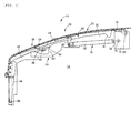
- Fig. 7 illustrates a half-opened state of an openable/closable type cover device 90 which is another embodiment of the claimable invention.
- the cover device 90 is provided with supporting members 92 and 94 which stably support a free end of the second cover portion 26 in each of the half-opened state illustrated in the drawing of the openable/closable cover 28, and in the entirely opened state which is not illustrated.
- the operator holds the tip end of the second cover portion 26 of the openable/closable cover 28 and make the tip end be in the half-opened state or in the entirely opened state, and in this state, by supporting a supported pin 96 which is a supported portion provided in the second cover portion 26 by the supporting members 92 and 94, it is possible to stably hold the openable/closable cover 28 in the half-opened state and in the entirely opened state.
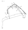
- Fig. 8 illustrates a half-opened state of an openable/closable type cover device 100 which is still another embodiment of the claimable invention.
- the openable/closable type cover device 100 is provided with a guide rail 102 and a linking device 104 instead of the guiding device 50 in the previous embodiment.
- the guide rail 102 has a simple shape which does not have the curved portions 60 and 61 in the previous embodiment, and a function of holding the openable/closable cover 28 in the half-opened state and in the entirely opened state is achieved by the linking device 104.
- the linking device 104 is provided with a linking link 106 which is attached to the second cover portion 26 to be relatively swingable, and an engaged pin 108 which is an engaged portion provided in the first cover portion 22.
- an engagement cutout 110 which is an engagement portion at a plurality of locations (two locations in the example illustrated in the drawing) in a longitudinal direction, one of the plurality engagement cutouts 110 is engaged with the engaging pin 108, a relative swing position of the first cover portion 22 and the second cover portion 26 is fixed, and according to this, the openable/closable cover 28 is stably maintained in the half-opened state or in the entirely opened state.
Landscapes
- Engineering & Computer Science (AREA)
- Civil Engineering (AREA)
- Structural Engineering (AREA)
- Mechanical Engineering (AREA)
- Operations Research (AREA)
- Manufacturing & Machinery (AREA)
- Microelectronics & Electronic Packaging (AREA)
- Supply And Installment Of Electrical Components (AREA)
- Casings For Electric Apparatus (AREA)
Abstract
Description
- The present invention relates to an openable/closable type cover device which covers an upper part of a work space on a work machine main body of a circuit board work machine that performs work with respect to an electronic circuit board, such as a screen printer which prints a cream type solder paste on the electronic circuit board, a component mounting machine which mounts an electronic circuit component on the electronic circuit board, or an electronic circuit board inspection machine which performs inspection of the electronic circuit board which has the electronic circuit component mounted thereon.
- PTL 1 described below discloses an example of an openable/closable type cover device. The openable/closable type cover device covers an upper part of a printing work space of a screen printer, includes a first cover portion which is attached to a main body of a printer to be swingable around a first swinging shaft line, and a second cover portion which is attached to a free end of the first cover portion to be swingable around a second swinging shaft line which is parallel to the first swinging shaft line, and can open the printing work space upward in a two-folded state where the second swinging shaft line moves relatively upward with respect to the first swinging shaft line. The two-foldable type cover device has an advantage that an opening/closing operation while covering a wide work space is easily performed, compared to an integrated swinging type cover device in which an integrated cover swings around one swinging shaft line.
- PTL 1:
JP-A-2011-230353 - However, inventors of the invention have found that there is a room for further improvement in the two-foldable type cover device described in PTL 1. In a case where the work space is wide, it is not always necessary to open the entire upper part of the wide work space, and sometimes it is sufficient if only a part thereof is opened. Nevertheless, the inventors have found that, since the two-foldable type cover device described in PTL 1 can be stabilized only in two states, including a state where the entire two-foldable type cover device is opened and a state where the entire two-foldable type cover device is closed, there are problems that the opening/closing operation which is more excessive than necessary is required, or the work space is opened too wide. The invention is based on this discovery, and a task of the invention is to improve the two-foldable type cover device of a circuit board work machine.
- The above-described problem is solved by making the two-foldable type cover device of the circuit board work machine into a device which can stably hold at least one half-opened state in addition to an entirely closed state and an entirely opened state.
- In the circuit board work machine, in many cases, it is sufficient if the two-foldable type cover device is in one half-opened state, but if necessary, it is also possible to stably hold two or more half-opened states which have different levels of half-opening.
- In addition, the above-described "can stably hold the half-opened state" means the cover device can maintain the half-opened state even when a person releases a hand from the cover device.
- In this manner, when the two-foldable type cover device of the circuit board work machine can stably maintain at least one half-opened state, in a case where only a part of a circuit board work space may be opened upward, an unnecessarily excessive opening/closing operation is not necessary, or it is possible to avoid the work space from being opened too wide, and thus, an effect in which usability of the two-foldable type cover device is improved is obtained. Since there are many cases where it is necessary to hold temperature or humidity of the work space in a set range in the circuit board work machine, the effect of avoiding the work space from being opened too wide is significant.
- In addition, among circuit board work devices, when a device which has high frequency of being necessary to be opened upward can be intensively disposed in a region of being opened upward in a half-opened state, in many cases, it is sufficient to make the two-foldable type cover device be in the half-opened state, and it is possible to more effectively achieve the effect of the invention.
-
- [
Fig. 1] Fig. 1 is a perspective view illustrating a housing of a component mounting machine including an openable/closable type cover device which is an embodiment of a claimable invention which is an invention recognized to be claimable as a patent at the time of filing of the present application. - [
Fig. 2] Fig. 2 is a partially enlarged view of the housing. - [
Fig. 3] Fig. 3 is a side surface sectional view illustrating an entirely closed state of the openable/closable type cover device. - [
Fig. 4] Fig. 4 is a side surface sectional view illustrating a half-opened state of the openable/closable type cover device. - [
Fig. 5] Fig. 5 is a side surface sectional view illustrating an entirely opened state of the openable/closable type cover device. - [
Fig. 6] Fig. 6 is a view illustrating an intermediate portion of a guide rail and a flip-up type guide which is provided in the vicinity thereof in a guiding device of the openable/closable type cover device.Fig. 6(a) illustrates a usual state,Fig. 6(b) illustrates a state where a roller is allowed to pass, andFigs. 6 (c) and 6 (d) illustrate a state where the roller is bridged. - [
Fig. 7] Fig. 7 is a side surface sectional view illustrating a half-opened state of the openable/closable type cover device which is another embodiment of the claimable invention. - [
Fig. 8] Fig. 8 is a side surface sectional view illustrating a half-opened state of the openable/closable type cover device which is still another embodiment of the claimable invention. - Hereinafter, several embodiments of the claimable invention will be described with reference to the above-described drawings. In addition, the claimable invention can be realized in aspects which are changed in various manners based on knowledge of those skilled in the art, in addition to the embodiments which will be described below.
-
Fig. 1 illustrates ahousing 10 of a component mounting machine which mounts an electronic circuit component on a circuit board. Thehousing 10 includes a mounting machinemain body 12 and an openable/closable type cover device (hereinafter, referred to as a cover device) 14. The component mounting machine is one type of a circuit board work machine which performs work with respect to the circuit board. An electronic circuit board manufacturing line which manufactures the electronic circuit board is configured such that the circuit work machine, an additional component mounting machine, a screen printer which prints a cream type solder paste on the circuit board, an adhesive applying machine which applies an adhesive to the circuit board, and an electronic circuit board inspection machine which inspects an electronic circuit board, are disposed to be adjacent to the component mounting machine. For this reason, anopening 16 is formed on a side surface of the mounting machinemain body 12, board conveyors are installed in two lanes in the front and the rear, passing through theopening 16, and the component mounting machine mounts the electronic circuit component on the circuit board which is conveyed into a component mounting space which is one of the circuit board work spaces by these board conveyors. In addition, areference numeral 18 indicates an observation window which is closed by a transparent plate. Theobservation window 18 is for visually recognizing the inside of the mounting machinemain body 12 in a state where the other circuit work machine is not disposed to be adjacent to the component mounting machine. - The
cover device 14 is attached to the mounting machinemain body 12 to be openable and closable in order to cover an upper part of the component mounting space, and as described inFigs. 3 to 5 , includes afirst cover portion 22 which is attached to the mounting machinemain body 12 to be swingable around a first swingingshaft line 20 which is parallel to a horizontal direction, and asecond cover portion 26 which is attached to a free end of thefirst cover portion 22 to be swingable around a second swingingshaft line 24 which is parallel to the first swingingshaft line 20. Accordingly, as described inFigs. 4 and5 , an openable/closable cover 28 of the openable/closable cover device 14 is a two-foldable type which can open the component mounting space upward in a two-folded state where the second swingingshaft line 24 moves relatively upward with respect to the first swingingshaft line 20. Both thefirst cover portion 22 and thesecond cover portion 26 are made of a transparent material, and even in an entirely closed state, the inside of the space can be seen through as illustrated inFig. 2 . - As apparently seen in
Fig. 1 , in thesecond cover portion 26, acutout 32 is formed at a part except for aright corner portion 30 of a free end portion, and a component supply portion of a component supply section, such as a tape feeder or a tray feeder, which is not illustrated, can protrude into the component mounting space through thecutout 32. In addition, in a left end portion of thecutout 32, as illustrated inFigs. 3 to 5 , aholding arm 34 is fixed in a state of extending parallel to theright corner portion 30, and each roller 36 (a roller of theright corner portion 30 is not illustrated in the drawing) is attached to a lower end of theholding arm 34 and theright corner portion 30 to be swingable around the horizontal swinging shaft line. In addition, as illustrated inFig. 1 , anoperation device 40 having a display is installed in front of theright corner portion 30 of thecover device 14 which is in an entirely closed state. However, since theoperation device 40 is held to be swingable around a perpendicular swinging shaft by a supportingshaft 42, theoperation device 40 is withdrawn to a position which is illustrated with a two-dotted chain line as necessary, and it is possible to avoid interference of thesecond cover portion 26 or disturbance of an access of an operator to the component mounting space. - The
cover device 14 is opened and closed while being guided by a guidingdevice 50 illustrated inFig. 3 or the like. The guidingdevice 50 includes aguide rail 52 which is provided on a side wall inner surface of the mounting machinemain body 12, and a flip-uptype guide 54, theguide rail 52 is provided with an upstreamside guide portion 56, a downstreamside guide portion 58, andcurved portions roller 36 is supported and guided by each of upper surfaces thereof. The upstreamside guide portion 56 is generally inclined in a state of being lowered to a front portion, and the downstreamside guide portion 58 also has a similarly inclined part. However, a front end portion is a steeply inclined portion which is nearly vertical. In addition, thecurved portion 60 is provided as a part which is curved downward between the upstreamside guide portion 56 and the downstreamside guide portion 58, and the flip-uptype guide 54 is provided to be swingable around a horizontal swingingshaft line 62 above an opening portion which is opened above thecurved portion 60. The flip-uptype guide 54 is provided with afirst arm 64 and asecond arm 66 on both sides of theswinging shaft line 62, is in a state where a free end of thefirst arm 64 is always supported by the upstreamside guide portion 56 from below by an elastic member, such as a torsion coil spring which is not illustrated, and is continuous with the upstreamside guide portion 56, and becomes in a state where a free end of thesecond arm 66 is supported by the downstreamside guide portion 58 from below, and is continuous with the downstreamside guide portion 58 when being swung against the elastic force of an elastic member. - As illustrated in
Fig. 3 or the like, in acurved arm 70, a base end portion of thefirst cover portion 22 is attached to a supportingmember 72 which is fixed to the mounting machinemain body 12 to be swingable around the horizontal first swingingshaft line 20, and an assistingcylinder 74 is also attached to the supportingmember 72 to be swingable around the horizontal swingingshaft line 76. Apiston rod 78 of the assistingcylinder 74 is linked to anarm 80 which is fixed to a part separated from the first swingingshaft line 20 of thefirst cover portion 22 to be relatively swingable. The assistingcylinder 74 is a cylinder in which gas is pressurized inside acylinder tube 82, and thepiston rod 78 is biased in a protruding direction by pressure of the gas. As apparently illustrated inFigs. 3 to 5 , while a force which is necessary for operating thecover device 14 from an entirely closed state to an entirely opened state decreases when approaching the entirely opened state, the assistingcylinder 74 is contracted at the maximum when thecover device 14 is in the entirely closed state, and is disposed to extend at the maximum when thecover device 14 is in the entirely opened state. In other words, the assistingcylinder 74 is always biased in a direction in which thecover device 14 is opened, but the biasing force is set to be slightly smaller than the force which is necessary for opening thecover device 14, and as a result, thecover device 14 is always held in the entirely closed state, and the assistingcylinder 74 assists the operator to open thecover device 14 only with a small force. In addition, in other words, instead of the assistingcylinder 74, it is possible to use an assisting cylinder which has an elastic member, such as a compression coil spring, embedded therein, or an assisting device including an elastic member or a guiding device which can expand and contract. - When it is necessary to make the
cover device 14 which is configured as described above be in a half-opened state, if the operator put a hand at a tip end (a dedicated handle which is provided in the vicinity of the tip end may be employed) of thesecond cover portion 26 and pull up theroller 36 while maintaining a motion of slightly pushing theroller 36 to theguide rail 52, theroller 36 is raised while being guided to an upper surface of the downstreamside guide portion 58 and reaches thecurved portion 60. At this time, since thesecond arm 66 is separated from the downstreamside guide portion 58 in the flip-uptype guide 54, advancement of theroller 36 to thecurved portion 60 is not disturbed, theroller 36 falls into thecurved portion 60, and further raising is hindered by a steeply raised part of thecurved portion 60. Even when the operator release a hand from the tip end of thesecond cover portion 26 in this state, as theroller 36 is supported by thecurved portion 60, the openable/closable cover 28 stably maintains a half-opened state illustrated inFig. 4 . Therefore, the operator can perform necessary work with respect to the front portion of a mounting work space. In the embodiment, in a state where the openable/closable cover 28 is opened halfway, upper parts of the component supply portion of the component supply section and the front portion of the work space which is near the component supply portion are opened, and thus, the operator can perform work with respect to these parts. Since a two-foldable type cover device in the related art cannot stably maintain the half-opened state, the device has to be always in the entirely opened state, a position of the tip end of the second cover portion in the entirely opened state becomes far, and in a state where the component supply section is set to be in the mounting machine main body, the operator is interrupted by the component supply section, cannot operate the tip end of the second cover portion, and has to remove the component supply section. Meanwhile, in the embodiment, while the component supply section is set to be in the mounting machinemain body 12, it is possible to make the openable/closable cover 28 be in the half-opened state, and to perform work with respect to the front portion of the work space. - When it is necessary to access a much deeper part of the mounting work space, that is, a rear portion, the operator pulls the
second cover portion 26 which is in a state ofFig. 4 further upward. Accordingly, theroller 36 flips up and detaches the first arm of the flip-uptype guide 54 which is in a state ofFig. 6(a) from thecurved portion 60 as illustrated inFig. 6(b) , and becomes in a state of being guided on an upper surface of the upstreamside guide portion 56. In addition, in a state where theroller 36 falls into thecurved portion 61 illustrated inFig. 5 , even when the operator releases a hand from thesecond cover portion 26, since the openable/closable cover 28 stably maintains the entirely opened state ofFig. 5 , the operator can perform work with respect to the rear portion of the mounting work space. It is possible to perform work with respect to the two lanes of board conveyors and board holding devices which correspond thereto, and further, in the embodiment, it is possible to perform attaching and detaching work of a HEPA filter of an air cleaning device which is not illustrated and which is provided in an upper portion of the mounting work space. - When returning the openable/
closable cover 28 in the entirely opened state to be in the entirely closed state, the operator may simply pull the tip end forward after putting a hand to the tip end of thesecond cover portion 26 and pulling up the tip end. Accordingly, theroller 36 is guided to the upstreamside guide portion 56 and reaches the upper part of thecurved portion 60, but as illustrated inFig. 6(c) , since thefirst arm 64 is in a state of being continuous with the upstream side guide in the flip-uptype guide 54, theroller 36 does not fall into thecurved portion 60. In addition, as illustrated inFig. 6(c) , theroller 36 moves on thefirst arm 64, and soon reaches above thesecond arm 66. As a result, since the flip-uptype guide 54 swings until a state illustrated inFig. 6 (d) is achieved against the elastic force of the elastic member, and theroller 36 is bridged to the downstreamside guide portion 58, the openable/closable cover 28 can easily return to the entirely closed state. - In addition, in the description above, guiding of the
roller 36 which is provided in the left end portion of thesecond cover portion 26 is described, but the guiding device of theroller 36 which is not illustrated and is provided in the right end portion is also configured similarly to the guidingdevice 50, and theroller 36 is similarly guided. - However, it is not essential to provide the roller and the guiding device thereof even in the right end portion of the
second cover portion 26. For example, it is possible to omit the roller and the guiding device thereof when the width of the pair circuit board work machine is narrow, or when rigidity of the cover device is high. - In addition, in the above-described embodiment, the
roller 36 is simply supported by a guiding surface of the guidingdevice 50. However, it is possible to provide a floating-up preventing member which is provided with a floating-up preventing surface which extends substantially parallel to each of the guiding surfaces except for thecurved portion 60 of theguide rail 52, and the upper surface of the flip-uptype guide 54 which is in a usual state, and to prevent theroller 36 from being excessively separated from the guide rail or the like. - In addition, when the free ends of the
first arm 64 and thesecond arm 66 of the flip-uptype guide 54 are supported by the upstreamside guide portion 56 and the downstreamside guide portion 58 from below, each of thearms guide portions type guide 54 and in a reverse direction thereto may be provided. - Furthermore, in order to make the
first arm 64 be in a state of being usually continuous with the upstreamside guide portion 56, using the elastic force or the like of the elastic member in the flip-uptype guide 54 is desirable since a desirable state can be reliably maintained, but this is not essential. For example, by making thefirst arm 64 heavier than thesecond arm 66, the flip-uptype guide 54 can usually be maintained in a state where thefirst arm 64 is continuous with the upstreamside guide portion 56 by a difference in a swing moment between thefirst arm 64 and thesecond arm 66. -
Fig. 7 illustrates a half-opened state of an openable/closabletype cover device 90 which is another embodiment of the claimable invention. Instead of the guidingdevice 50 in the previous embodiment, thecover device 90 is provided with supportingmembers second cover portion 26 in each of the half-opened state illustrated in the drawing of the openable/closable cover 28, and in the entirely opened state which is not illustrated. In the embodiment, the operator holds the tip end of thesecond cover portion 26 of the openable/closable cover 28 and make the tip end be in the half-opened state or in the entirely opened state, and in this state, by supporting a supportedpin 96 which is a supported portion provided in thesecond cover portion 26 by the supportingmembers closable cover 28 in the half-opened state and in the entirely opened state. - In addition, even in the embodiment, as illustrated with a two-dotted chain line, there are many cases where providing an excessive
advancement preventing portion 98 which prevents the tip end of thesecond cover portion 26 from excessively advancing into the mounting work space is not essential but effective. -
Fig. 8 illustrates a half-opened state of an openable/closabletype cover device 100 which is still another embodiment of the claimable invention. The openable/closabletype cover device 100 is provided with aguide rail 102 and alinking device 104 instead of the guidingdevice 50 in the previous embodiment. Theguide rail 102 has a simple shape which does not have thecurved portions closable cover 28 in the half-opened state and in the entirely opened state is achieved by the linkingdevice 104. The linkingdevice 104 is provided with a linkinglink 106 which is attached to thesecond cover portion 26 to be relatively swingable, and an engagedpin 108 which is an engaged portion provided in thefirst cover portion 22. As thelinking link 106 is provided with anengagement cutout 110 which is an engagement portion at a plurality of locations (two locations in the example illustrated in the drawing) in a longitudinal direction, one of theplurality engagement cutouts 110 is engaged with theengaging pin 108, a relative swing position of thefirst cover portion 22 and thesecond cover portion 26 is fixed, and according to this, the openable/closable cover 28 is stably maintained in the half-opened state or in the entirely opened state. -
- 10: HOUSING, 12: MOUNTING MACHINE MAIN BODY, 14: OPENABLE/CLOSABLE TYPE COVER DEVICE, 20: FIRST SWINGING SHAFT LINE, 22: FIRST COVER PORTION, 24: SECOND SWINGING SHAFT LINE, 26: SECOND COVER PORTION, 28: OPENABLE/CLOSABLE COVER, 34: HOLDING ARM, 36: ROLLER, 50: GUIDING DEVICE, 52: GUIDE RAIL, 54: FLIP-UP TYPE GUIDE, 56: UPSTREAM SIDE GUIDE PORTION, 58: DOWNSTREAM SIDE GUIDE PORTION, 60, 61: CURVED PORTION, 62: SWINGING SHAFT LINE, 64: FIRST ARM, 66: SECOND ARM, 74: ASSISTING CYLINDER, 90: COVER DEVICE, 92, 94: SUPPORTING MEMBER, 94: SUPPORTED PIN, 100: COVER DEVICE, 102: GUIDE RAIL, 104: LINKING DEVICE
Claims (8)
- An openable/closable type cover device which covers an upper part of a work space on a work machine main body of a circuit board work machine that performs work with respect to an electronic circuit board, the device comprising:a first cover portion which is attached to the work machine main body to be swingable around a first swinging shaft line; anda second cover portion which is attached to a free end of the first cover portion to be swingable around a second swinging shaft line which is parallel to the first swinging shaft line,wherein the work space can be opened upward in a two-folded state where the second swinging shaft line moves relatively upward with respect to the first swinging shaft line, and at least one half-opened state can be stably held in addition to an entirely closed state and an entirely opened state.
- The openable/closable type cover device according to Claim 1, further comprising:a second cover portion supporting device which stably supports a free end of the second cover portion in the entirely opened state and in the at least one half-opened state.
- The openable/closable type cover device according to Claim 2,
wherein the second cover portion supporting device includes a guide rail which is fixed to the work machine main body, and a guided portion which is attached to the second cover portion and guided to the guide rail. - The openable/closable type cover device according to Claim 3,
wherein, as the guide rail includes at least one curved portion which is curved downward at an intermediate portion, and the guided portion falls into the curved portion, the openable/closable type cover device can be stable in the at least one half-opened state. - The openable/closable type cover device according to Claim 4,
wherein the guide rail includes an upstream side guide portion which is positioned to be closer to the first swinging shaft line side than the curved portion, and a downstream side guide portion which is positioned on a side opposite to the upstream side guide portion with respect to the curved portion, and
the openable/closable type cover device includes a flip-up type guide which is provided above the curved portion to be swingable around a horizontal shaft line, which is provided with a first arm and a second arm that extend to both sides of the horizontal shaft line, which is normally in a state where a free end of the first arm is continuous to the upstream side guide portion,
wherein the guided portion flips up the first arm upward and moves to the upstream side guide portion when the guided portion which falls into the curved portion moves toward the upstream side guide portion, and
wherein the first arm supports the guided portion and prevents the guided portion from falling into the curved portion and the flip-up type guide swings around the horizontal shaft line after the guided portion passes through the horizontal shaft line thereby the second arm portion is linked to the downstream side guide portion when the guided portion moves to the downstream side guide portion from the upstream side guide portion. - The openable/closable type cover device according to Claim 5,
wherein the first arm and the second arm are respectively in a state of being linked to the upstream side guide portion and the downstream side guide portion as each free end of the first arm and the second arm of the flip-up type guide is supported by the upstream side guide portion and the downstream side guide portion from below. - The openable/closable type cover device according to Claim 5 or 6, further comprising:an elastic member which biases the flip-up type guide in a swinging direction so that the free end of the first arm is linked to the upstream side guide portion.
- The openable/closable type cover device according to any one of Claims 1 to 7, further comprising:a biasing device which makes an opening operation of the cover device easy as the first cover portion and the second cover portion are biased to be in the two-folded state, but allows a closed state to be held.
Applications Claiming Priority (1)
| Application Number | Priority Date | Filing Date | Title |
|---|---|---|---|
| PCT/JP2013/052203 WO2014118939A1 (en) | 2013-01-31 | 2013-01-31 | Opening/closing cover device for circuit board work machine |
Publications (3)
| Publication Number | Publication Date |
|---|---|
| EP2953438A1 true EP2953438A1 (en) | 2015-12-09 |
| EP2953438A4 EP2953438A4 (en) | 2016-02-10 |
| EP2953438B1 EP2953438B1 (en) | 2017-10-11 |
Family
ID=51261684
Family Applications (1)
| Application Number | Title | Priority Date | Filing Date |
|---|---|---|---|
| EP13873180.7A Active EP2953438B1 (en) | 2013-01-31 | 2013-01-31 | Opening/closing cover device for circuit board work machine |
Country Status (5)
| Country | Link |
|---|---|
| US (1) | US10316580B2 (en) |
| EP (1) | EP2953438B1 (en) |
| JP (1) | JP6118352B2 (en) |
| CN (1) | CN104956787B (en) |
| WO (1) | WO2014118939A1 (en) |
Families Citing this family (12)
| Publication number | Priority date | Publication date | Assignee | Title |
|---|---|---|---|---|
| JP6752011B2 (en) * | 2015-11-09 | 2020-09-09 | 株式会社Fuji | Break-action opening / closing mechanism |
| CA166896S (en) | 2015-12-17 | 2016-09-23 | Sport Maska Inc | Helmet visor |
| USD824701S1 (en) * | 2017-02-16 | 2018-08-07 | Jiangxi Hili Electric Appliances Technology Co., Ltd | Mobile file cabinet |
| JP7049813B2 (en) * | 2017-11-20 | 2022-04-07 | 株式会社ディスコ | Processing equipment |
| JP7155519B2 (en) * | 2017-12-22 | 2022-10-19 | パナソニックIpマネジメント株式会社 | working equipment |
| JP7178546B2 (en) * | 2018-07-04 | 2022-11-28 | パナソニックIpマネジメント株式会社 | Parts mounting device |
| DE102019006945A1 (en) * | 2018-10-11 | 2020-04-16 | Makita Corporation | Accumulator mounting device |
| CN109649009A (en) * | 2018-12-10 | 2019-04-19 | 深圳劲鑫科技有限公司 | A kind of spray printing device outer cover maintenance valve mechanism |
| JP7284495B2 (en) * | 2019-02-04 | 2023-05-31 | セムコ株式会社 | Switchgear and screw feeder |
| FR3122173B1 (en) * | 2021-04-22 | 2023-06-02 | Pa Cotte Sa | Foldable package comprising means for guiding a lid |
| CN114412329B (en) * | 2022-01-27 | 2023-11-10 | 苏州华瑞腾航空设备有限公司 | Folding top cover and aviation dining car |
| JP2023134926A (en) * | 2022-03-15 | 2023-09-28 | セイコーエプソン株式会社 | recording device |
Family Cites Families (23)
| Publication number | Priority date | Publication date | Assignee | Title |
|---|---|---|---|---|
| US1471781A (en) * | 1922-11-15 | 1923-10-23 | Empire Biscuit Co | Display cover for containers |
| US1773730A (en) * | 1929-01-14 | 1930-08-26 | Knudsen | Window sash and casing |
| US1945729A (en) * | 1932-06-03 | 1934-02-06 | Elliott A Callender | Protective device for windows |
| US2946304A (en) * | 1956-03-12 | 1960-07-26 | G M E Corp | Hatch cover assembly |
| US3045746A (en) * | 1958-03-25 | 1962-07-24 | Mac Gregor Comarain Sa | Method and means for mounting and operating hingedly interconnected panel elements for closing hatchways, railway cars and like open spaces |
| US3022818A (en) * | 1960-06-30 | 1962-02-27 | Int Paper Co | Doorway closure |
| US3219101A (en) * | 1962-05-10 | 1965-11-23 | Martin Fleit | Awning |
| JPH062291Y2 (en) * | 1986-11-04 | 1994-01-19 | ソニー株式会社 | Operation panel tilt adjustment mechanism |
| JPH0740057Y2 (en) * | 1989-05-19 | 1995-09-13 | 株式会社ニフコ | Raising and lowering devices such as operating parts in electronic devices |
| JP2777853B2 (en) | 1992-06-30 | 1998-07-23 | ファナック株式会社 | Machinery with display and manual input device |
| KR0130587Y1 (en) * | 1995-11-09 | 1998-12-15 | 김광호 | Lid of washing machine |
| JP3260107B2 (en) * | 1997-08-18 | 2002-02-25 | 株式会社ピーエフユー | Display device |
| DE69922467T2 (en) * | 1998-09-25 | 2005-12-15 | Matsushita Electric Industrial Co., Ltd., Kadoma | Component actuator and safety device therefor |
| JP4551008B2 (en) * | 2001-02-16 | 2010-09-22 | 株式会社日立ハイテクインスツルメンツ | Cover device for component supply unit in electronic component mounting device |
| JP2003089035A (en) * | 2001-09-17 | 2003-03-25 | Tokyo Seimitsu Co Ltd | Grinding device |
| US6863358B2 (en) * | 2002-02-28 | 2005-03-08 | Haworth, Inc. | Storage cabinet with movable door |
| JP2006091154A (en) * | 2004-09-21 | 2006-04-06 | Toshiba Corp | Close assist device and image forming apparatus provided with the same |
| JP2007180414A (en) * | 2005-12-28 | 2007-07-12 | Juki Corp | Surface mount equipment |
| JP5029223B2 (en) * | 2007-08-28 | 2012-09-19 | 村田機械株式会社 | Machine tool with partition plate |
| DE102008056734B3 (en) * | 2008-11-11 | 2010-07-22 | Siemens Electronics Assembly Systems Gmbh & Co. Kg | Automatic assembly machine for assembling electronic member on substrate, has door frame system continuously used when operator operates in member pick-up zone, where member pick-up zone and assembly zone are separated in space |
| JP5589376B2 (en) * | 2009-12-21 | 2014-09-17 | セイコーエプソン株式会社 | Cover unit and printer |
| JP5700951B2 (en) | 2010-04-27 | 2015-04-15 | 富士機械製造株式会社 | Screen printing machine |
| JP5858642B2 (en) * | 2011-05-16 | 2016-02-10 | ヤマハ発動機株式会社 | Printing device |
-
2013
- 2013-01-31 CN CN201380071625.0A patent/CN104956787B/en active Active
- 2013-01-31 JP JP2014559431A patent/JP6118352B2/en active Active
- 2013-01-31 US US14/764,642 patent/US10316580B2/en active Active
- 2013-01-31 EP EP13873180.7A patent/EP2953438B1/en active Active
- 2013-01-31 WO PCT/JP2013/052203 patent/WO2014118939A1/en not_active Ceased
Also Published As
| Publication number | Publication date |
|---|---|
| JP6118352B2 (en) | 2017-04-19 |
| JPWO2014118939A1 (en) | 2017-01-26 |
| US10316580B2 (en) | 2019-06-11 |
| EP2953438B1 (en) | 2017-10-11 |
| US20150368957A1 (en) | 2015-12-24 |
| CN104956787A (en) | 2015-09-30 |
| EP2953438A4 (en) | 2016-02-10 |
| CN104956787B (en) | 2017-12-05 |
| WO2014118939A1 (en) | 2014-08-07 |
Similar Documents
| Publication | Publication Date | Title |
|---|---|---|
| EP2953438B1 (en) | Opening/closing cover device for circuit board work machine | |
| JP6316737B2 (en) | Door safety device | |
| PL2179919T3 (en) | Aircraft with loading access opening | |
| EP2345346B8 (en) | Mattress encasement for preventing bed bug escapement via a zipper opening | |
| US9713283B2 (en) | Electronic apparatus and filter unit | |
| EP2107205A3 (en) | Smoke curtain | |
| JP6227919B2 (en) | Hook release prevention device | |
| EP2060527A3 (en) | Reel assembly | |
| WO2012124005A1 (en) | Tape feeder and parts mounting device | |
| US9296227B2 (en) | Printer including multiple cutter units that connect to each other through projections and grooves when lid is closed | |
| US11998867B2 (en) | Air filter having pulling elements | |
| CN105711271B (en) | Printing equipment | |
| CA2826529A1 (en) | Apparatus for ejecting an oxygen mask | |
| CN108353515A (en) | Supply unit | |
| EP2974873A2 (en) | Printer and paper guide | |
| JP6316650B2 (en) | Winding box in a winding screen device | |
| JP6607658B2 (en) | Sliding door closer with push latch | |
| CN103857271B (en) | Band edge processing unit | |
| ATE381659T1 (en) | DOOR ARRANGEMENT | |
| JP2015063353A5 (en) | ||
| US20190364678A1 (en) | Door opening and closing mechanism | |
| JP5303353B2 (en) | Structure for preventing the end of a long member from being attached to a long frame material | |
| US20160024836A1 (en) | Door opening and closing device | |
| CZ2011794A3 (en) | Device for preventing insect flight through | |
| CN205033735U (en) | Portable printer |
Legal Events
| Date | Code | Title | Description |
|---|---|---|---|
| PUAI | Public reference made under article 153(3) epc to a published international application that has entered the european phase |
Free format text: ORIGINAL CODE: 0009012 |
|
| 17P | Request for examination filed |
Effective date: 20150728 |
|
| AK | Designated contracting states |
Kind code of ref document: A1 Designated state(s): AL AT BE BG CH CY CZ DE DK EE ES FI FR GB GR HR HU IE IS IT LI LT LU LV MC MK MT NL NO PL PT RO RS SE SI SK SM TR |
|
| AX | Request for extension of the european patent |
Extension state: BA ME |
|
| A4 | Supplementary search report drawn up and despatched |
Effective date: 20160112 |
|
| RIC1 | Information provided on ipc code assigned before grant |
Ipc: H05K 13/08 20060101ALI20160106BHEP Ipc: H05K 3/34 20060101ALI20160106BHEP Ipc: H05K 13/04 20060101AFI20160106BHEP Ipc: B41F 15/08 20060101ALI20160106BHEP |
|
| DAX | Request for extension of the european patent (deleted) | ||
| 17Q | First examination report despatched |
Effective date: 20161212 |
|
| GRAP | Despatch of communication of intention to grant a patent |
Free format text: ORIGINAL CODE: EPIDOSNIGR1 |
|
| INTG | Intention to grant announced |
Effective date: 20170522 |
|
| GRAS | Grant fee paid |
Free format text: ORIGINAL CODE: EPIDOSNIGR3 |
|
| GRAA | (expected) grant |
Free format text: ORIGINAL CODE: 0009210 |
|
| AK | Designated contracting states |
Kind code of ref document: B1 Designated state(s): AL AT BE BG CH CY CZ DE DK EE ES FI FR GB GR HR HU IE IS IT LI LT LU LV MC MK MT NL NO PL PT RO RS SE SI SK SM TR |
|
| REG | Reference to a national code |
Ref country code: GB Ref legal event code: FG4D |
|
| REG | Reference to a national code |
Ref country code: CH Ref legal event code: EP |
|
| REG | Reference to a national code |
Ref country code: IE Ref legal event code: FG4D |
|
| REG | Reference to a national code |
Ref country code: AT Ref legal event code: REF Ref document number: 937119 Country of ref document: AT Kind code of ref document: T Effective date: 20171115 |
|
| REG | Reference to a national code |
Ref country code: DE Ref legal event code: R096 Ref document number: 602013027969 Country of ref document: DE |
|
| REG | Reference to a national code |
Ref country code: NL Ref legal event code: MP Effective date: 20171011 |
|
| REG | Reference to a national code |
Ref country code: LT Ref legal event code: MG4D |
|
| REG | Reference to a national code |
Ref country code: AT Ref legal event code: MK05 Ref document number: 937119 Country of ref document: AT Kind code of ref document: T Effective date: 20171011 |
|
| PG25 | Lapsed in a contracting state [announced via postgrant information from national office to epo] |
Ref country code: NL Free format text: LAPSE BECAUSE OF FAILURE TO SUBMIT A TRANSLATION OF THE DESCRIPTION OR TO PAY THE FEE WITHIN THE PRESCRIBED TIME-LIMIT Effective date: 20171011 |
|
| PG25 | Lapsed in a contracting state [announced via postgrant information from national office to epo] |
Ref country code: SE Free format text: LAPSE BECAUSE OF FAILURE TO SUBMIT A TRANSLATION OF THE DESCRIPTION OR TO PAY THE FEE WITHIN THE PRESCRIBED TIME-LIMIT Effective date: 20171011 Ref country code: FI Free format text: LAPSE BECAUSE OF FAILURE TO SUBMIT A TRANSLATION OF THE DESCRIPTION OR TO PAY THE FEE WITHIN THE PRESCRIBED TIME-LIMIT Effective date: 20171011 Ref country code: ES Free format text: LAPSE BECAUSE OF FAILURE TO SUBMIT A TRANSLATION OF THE DESCRIPTION OR TO PAY THE FEE WITHIN THE PRESCRIBED TIME-LIMIT Effective date: 20171011 Ref country code: NO Free format text: LAPSE BECAUSE OF FAILURE TO SUBMIT A TRANSLATION OF THE DESCRIPTION OR TO PAY THE FEE WITHIN THE PRESCRIBED TIME-LIMIT Effective date: 20180111 Ref country code: LT Free format text: LAPSE BECAUSE OF FAILURE TO SUBMIT A TRANSLATION OF THE DESCRIPTION OR TO PAY THE FEE WITHIN THE PRESCRIBED TIME-LIMIT Effective date: 20171011 |
|
| PG25 | Lapsed in a contracting state [announced via postgrant information from national office to epo] |
Ref country code: HR Free format text: LAPSE BECAUSE OF FAILURE TO SUBMIT A TRANSLATION OF THE DESCRIPTION OR TO PAY THE FEE WITHIN THE PRESCRIBED TIME-LIMIT Effective date: 20171011 Ref country code: AT Free format text: LAPSE BECAUSE OF FAILURE TO SUBMIT A TRANSLATION OF THE DESCRIPTION OR TO PAY THE FEE WITHIN THE PRESCRIBED TIME-LIMIT Effective date: 20171011 Ref country code: IS Free format text: LAPSE BECAUSE OF FAILURE TO SUBMIT A TRANSLATION OF THE DESCRIPTION OR TO PAY THE FEE WITHIN THE PRESCRIBED TIME-LIMIT Effective date: 20180211 Ref country code: LV Free format text: LAPSE BECAUSE OF FAILURE TO SUBMIT A TRANSLATION OF THE DESCRIPTION OR TO PAY THE FEE WITHIN THE PRESCRIBED TIME-LIMIT Effective date: 20171011 Ref country code: BG Free format text: LAPSE BECAUSE OF FAILURE TO SUBMIT A TRANSLATION OF THE DESCRIPTION OR TO PAY THE FEE WITHIN THE PRESCRIBED TIME-LIMIT Effective date: 20180111 Ref country code: RS Free format text: LAPSE BECAUSE OF FAILURE TO SUBMIT A TRANSLATION OF THE DESCRIPTION OR TO PAY THE FEE WITHIN THE PRESCRIBED TIME-LIMIT Effective date: 20171011 Ref country code: GR Free format text: LAPSE BECAUSE OF FAILURE TO SUBMIT A TRANSLATION OF THE DESCRIPTION OR TO PAY THE FEE WITHIN THE PRESCRIBED TIME-LIMIT Effective date: 20180112 |
|
| REG | Reference to a national code |
Ref country code: DE Ref legal event code: R097 Ref document number: 602013027969 Country of ref document: DE |
|
| PG25 | Lapsed in a contracting state [announced via postgrant information from national office to epo] |
Ref country code: EE Free format text: LAPSE BECAUSE OF FAILURE TO SUBMIT A TRANSLATION OF THE DESCRIPTION OR TO PAY THE FEE WITHIN THE PRESCRIBED TIME-LIMIT Effective date: 20171011 Ref country code: DK Free format text: LAPSE BECAUSE OF FAILURE TO SUBMIT A TRANSLATION OF THE DESCRIPTION OR TO PAY THE FEE WITHIN THE PRESCRIBED TIME-LIMIT Effective date: 20171011 Ref country code: CZ Free format text: LAPSE BECAUSE OF FAILURE TO SUBMIT A TRANSLATION OF THE DESCRIPTION OR TO PAY THE FEE WITHIN THE PRESCRIBED TIME-LIMIT Effective date: 20171011 Ref country code: SK Free format text: LAPSE BECAUSE OF FAILURE TO SUBMIT A TRANSLATION OF THE DESCRIPTION OR TO PAY THE FEE WITHIN THE PRESCRIBED TIME-LIMIT Effective date: 20171011 |
|
| PLBE | No opposition filed within time limit |
Free format text: ORIGINAL CODE: 0009261 |
|
| STAA | Information on the status of an ep patent application or granted ep patent |
Free format text: STATUS: NO OPPOSITION FILED WITHIN TIME LIMIT |
|
| PG25 | Lapsed in a contracting state [announced via postgrant information from national office to epo] |
Ref country code: SM Free format text: LAPSE BECAUSE OF FAILURE TO SUBMIT A TRANSLATION OF THE DESCRIPTION OR TO PAY THE FEE WITHIN THE PRESCRIBED TIME-LIMIT Effective date: 20171011 Ref country code: IT Free format text: LAPSE BECAUSE OF FAILURE TO SUBMIT A TRANSLATION OF THE DESCRIPTION OR TO PAY THE FEE WITHIN THE PRESCRIBED TIME-LIMIT Effective date: 20171011 Ref country code: RO Free format text: LAPSE BECAUSE OF FAILURE TO SUBMIT A TRANSLATION OF THE DESCRIPTION OR TO PAY THE FEE WITHIN THE PRESCRIBED TIME-LIMIT Effective date: 20171011 Ref country code: PL Free format text: LAPSE BECAUSE OF FAILURE TO SUBMIT A TRANSLATION OF THE DESCRIPTION OR TO PAY THE FEE WITHIN THE PRESCRIBED TIME-LIMIT Effective date: 20171011 |
|
| REG | Reference to a national code |
Ref country code: CH Ref legal event code: PL |
|
| 26N | No opposition filed |
Effective date: 20180712 |
|
| REG | Reference to a national code |
Ref country code: DE Ref legal event code: R082 Ref document number: 602013027969 Country of ref document: DE Representative=s name: GRUENECKER PATENT- UND RECHTSANWAELTE PARTG MB, DE Ref country code: DE Ref legal event code: R081 Ref document number: 602013027969 Country of ref document: DE Owner name: FUJI CORPORATION, CHIRYU-SHI, JP Free format text: FORMER OWNER: FUJI MACHINE MFG. CO., LTD., CHIRYU-SHI, AICHI, JP |
|
| PG25 | Lapsed in a contracting state [announced via postgrant information from national office to epo] |
Ref country code: LU Free format text: LAPSE BECAUSE OF NON-PAYMENT OF DUE FEES Effective date: 20180131 Ref country code: FR Free format text: LAPSE BECAUSE OF NON-PAYMENT OF DUE FEES Effective date: 20180131 |
|
| REG | Reference to a national code |
Ref country code: IE Ref legal event code: MM4A |
|
| REG | Reference to a national code |
Ref country code: FR Ref legal event code: ST Effective date: 20180928 |
|
| REG | Reference to a national code |
Ref country code: BE Ref legal event code: MM Effective date: 20180131 |
|
| PG25 | Lapsed in a contracting state [announced via postgrant information from national office to epo] |
Ref country code: BE Free format text: LAPSE BECAUSE OF NON-PAYMENT OF DUE FEES Effective date: 20180131 Ref country code: LI Free format text: LAPSE BECAUSE OF NON-PAYMENT OF DUE FEES Effective date: 20180131 Ref country code: CH Free format text: LAPSE BECAUSE OF NON-PAYMENT OF DUE FEES Effective date: 20180131 Ref country code: SI Free format text: LAPSE BECAUSE OF FAILURE TO SUBMIT A TRANSLATION OF THE DESCRIPTION OR TO PAY THE FEE WITHIN THE PRESCRIBED TIME-LIMIT Effective date: 20171011 |
|
| PG25 | Lapsed in a contracting state [announced via postgrant information from national office to epo] |
Ref country code: IE Free format text: LAPSE BECAUSE OF NON-PAYMENT OF DUE FEES Effective date: 20180131 |
|
| PG25 | Lapsed in a contracting state [announced via postgrant information from national office to epo] |
Ref country code: MC Free format text: LAPSE BECAUSE OF FAILURE TO SUBMIT A TRANSLATION OF THE DESCRIPTION OR TO PAY THE FEE WITHIN THE PRESCRIBED TIME-LIMIT Effective date: 20171011 |
|
| PG25 | Lapsed in a contracting state [announced via postgrant information from national office to epo] |
Ref country code: MT Free format text: LAPSE BECAUSE OF NON-PAYMENT OF DUE FEES Effective date: 20180131 |
|
| PG25 | Lapsed in a contracting state [announced via postgrant information from national office to epo] |
Ref country code: TR Free format text: LAPSE BECAUSE OF FAILURE TO SUBMIT A TRANSLATION OF THE DESCRIPTION OR TO PAY THE FEE WITHIN THE PRESCRIBED TIME-LIMIT Effective date: 20171011 |
|
| PG25 | Lapsed in a contracting state [announced via postgrant information from national office to epo] |
Ref country code: PT Free format text: LAPSE BECAUSE OF FAILURE TO SUBMIT A TRANSLATION OF THE DESCRIPTION OR TO PAY THE FEE WITHIN THE PRESCRIBED TIME-LIMIT Effective date: 20171011 |
|
| PG25 | Lapsed in a contracting state [announced via postgrant information from national office to epo] |
Ref country code: MK Free format text: LAPSE BECAUSE OF NON-PAYMENT OF DUE FEES Effective date: 20171011 Ref country code: HU Free format text: LAPSE BECAUSE OF FAILURE TO SUBMIT A TRANSLATION OF THE DESCRIPTION OR TO PAY THE FEE WITHIN THE PRESCRIBED TIME-LIMIT; INVALID AB INITIO Effective date: 20130131 Ref country code: CY Free format text: LAPSE BECAUSE OF FAILURE TO SUBMIT A TRANSLATION OF THE DESCRIPTION OR TO PAY THE FEE WITHIN THE PRESCRIBED TIME-LIMIT Effective date: 20171011 |
|
| PG25 | Lapsed in a contracting state [announced via postgrant information from national office to epo] |
Ref country code: AL Free format text: LAPSE BECAUSE OF FAILURE TO SUBMIT A TRANSLATION OF THE DESCRIPTION OR TO PAY THE FEE WITHIN THE PRESCRIBED TIME-LIMIT Effective date: 20171011 |
|
| P01 | Opt-out of the competence of the unified patent court (upc) registered |
Effective date: 20230328 |
|
| PGFP | Annual fee paid to national office [announced via postgrant information from national office to epo] |
Ref country code: GB Payment date: 20251211 Year of fee payment: 14 |
|
| PGFP | Annual fee paid to national office [announced via postgrant information from national office to epo] |
Ref country code: DE Payment date: 20251210 Year of fee payment: 14 |