EP2953266A1 - Data compression device, data compression method, and program - Google Patents
Data compression device, data compression method, and program Download PDFInfo
- Publication number
- EP2953266A1 EP2953266A1 EP13836184.5A EP13836184A EP2953266A1 EP 2953266 A1 EP2953266 A1 EP 2953266A1 EP 13836184 A EP13836184 A EP 13836184A EP 2953266 A1 EP2953266 A1 EP 2953266A1
- Authority
- EP
- European Patent Office
- Prior art keywords
- data
- starting point
- timing
- input
- limit slope
- Prior art date
- Legal status (The legal status is an assumption and is not a legal conclusion. Google has not performed a legal analysis and makes no representation as to the accuracy of the status listed.)
- Granted
Links
Images







Classifications
-
- H—ELECTRICITY
- H03—ELECTRONIC CIRCUITRY
- H03M—CODING; DECODING; CODE CONVERSION IN GENERAL
- H03M7/00—Conversion of a code where information is represented by a given sequence or number of digits to a code where the same, similar or subset of information is represented by a different sequence or number of digits
- H03M7/30—Compression; Expansion; Suppression of unnecessary data, e.g. redundancy reduction
- H03M7/3059—Digital compression and data reduction techniques where the original information is represented by a subset or similar information, e.g. lossy compression
Definitions
- Embodiments of the present invention are related to a data compression device, a data compression method, and a program.
- a method of data compression is known in which, from time-series data that is input, point data constituting the time-series data is subjected to thinning.
- the Box Car algorithm the Backward Slope algorithm, and the Swinging Door algorithm are available.
- the Swinging Door algorithm is a representative example of the algorithms in which data thinning is achieved by performing linear approximation in such a way that the error is equal to or smaller than a predetermined threshold value.
- a single point is fixed as the starting point, and linear approximation is performed in such a way that the error is equal to or smaller than a predetermined threshold value.
- a data compression device includes a receiving unit, a generating unit, a selecting unit, and a compressing unit.
- the receiving receives a plurality of pieces of input data which is input in chronological order.
- the generating unit generates a plurality of starting point candidates which represents the data having an error within a threshold value with respect to starting point data.
- the starting point data is the input data input at a first timing.
- the selecting unit refers to the starting point candidates, end point data which is the input data input at a second timing, and intermediate data which is the input data input at a timing in between the first timing and the second timing; and selects, from among the starting point candidates, the starting point candidate which, as compared to the other starting point candidates, has a greater number of pieces of the intermediate data approximated using the starting point candidate and using the end point data in such a way that the error is within the threshold value.
- the compressing unit outputs the selected starting point candidate and the end point data as output data obtained by compressing the starting point data, the intermediate data, and the end point data.
- a single starting point is set and linear approximation is performed in order to compress time-series data.
- a plurality of starting points (starting point candidates) is set, and time-series data is compressed using such a starting point candidate which enables achieving compression in a more efficient manner.
- Time-series data points to a series of values (a point data string) obtained by observing or measuring temporal changes of a particular phenomenon.
- time-series data is measured at predetermined time intervals.
- Examples of time-series data include share prices and sensor values of an in-plant installation. For example, regarding a number of devices constituting an in-plant installation; a series of values of humidity, a series of values of vibrations, or a series of values of control setting can be said to form a single piece of time-series data.
- a time-series database is created by compiling time-series data.
- a time-series database a large volume of time-series data is stored in chronological order in a memory of a computer or in an external memory device (a hard disk).
- a data item which is the smallest unit of data storage is called a tag.
- a tag is made of a data value, a time stamp, a data status, and the like.
- the data that is to be collected has types such as operating data which is input from a control system, computational data which is obtained by implementing an online computation function, data which is manually input by an operator, and interface data which is input from other systems.
- a time-series database In a time-series database, generally, there are several thousands to several tens of thousands of tags.
- the data storage period for each tag ranges from one year to several years.
- the data collection cycle As far as the data collection cycle is concerned, although it is dependent on the real-time property of the concerned system (such as an in-plant installation); it ranges from a few seconds to one minute as a rough indication.
- a time-series database needs to have the database capacity of about 10 GB (gigabytes) to 10 TB (terabytes). If the database capacity is increased to that extent, then it is bound to cause deterioration in the retrieval performance.
- a technology of data compression is implemented by making use of the property that, during stable operations, the operating data undergoes only a small change.
- the behavior of the original data can be understood by referring to compressed data having the compression ratio of 1:20.
- FIG. 1 is a block diagram illustrating an exemplary configuration of a data compression device 100 according to the first embodiment.
- the data compression device 100 includes a receiving unit 101, a registering unit 110, a searching unit 114, and a memory unit 121.
- the receiving unit 101, the registering unit 110, and the searching unit 114 can be implemented, for example, by executing a program in a processor such as a CPU (Central Processing Unit), that is, can be implemented using software; or can be implemented using hardware such as an IC (Integrated Circuit); or can be implemented using a combination of software and hardware.
- a processor such as a CPU (Central Processing Unit)
- CPU Central Processing Unit
- hardware such as an IC (Integrated Circuit); or can be implemented using a combination of software and hardware.
- the memory unit 121 is used to store a variety of data.
- the memory unit 121 is used to store time-series data that has been compressed by a compressing unit 113.
- the memory unit 121 can be configured with any commonly-used memory medium such as an HDD (Hard Disk Drive), an optical disk, a memory card, and a RAM (Random Access Memory).
- the receiving unit 101 receives processing requests and data that are input from external devices such as client devices.
- a processing request points to, for example, a time-series data registration request or a time-series data search request.
- the receiving unit 101 receives a plurality of pieces of input data (point data of time-series data) that is input in chronological order.
- the receiving unit 101 can also receive pieces of point data that are input in real time.
- the receiving unit 101 stores the pieces of point data, which are input in real time, in the memory unit 121.
- the receiving unit 101 can receive pieces of point data in chronological order from the time-series data stored in the memory unit 121.
- the configuration can be such that the receiving unit 101 goes back in time to a particular timing serving as the starting point, that is, receives the pieces of point data in a sequential manner starting from an earlier timing.
- the registering unit 110 performs, based on an allowable error, an operation (a compression operation) of thinning a piece of point data from a series of point data that is input; and registers the post-thinning point data as time-series data in the memory unit 121.
- an operation a compression operation
- the registering unit 110 includes a generating unit 111, a selecting unit 112, and the compressing unit 113.
- the generating unit 111 generates a plurality of starting point candidates that represents data having an error within a predetermined threshold value with respect to starting point data, which is the point data at a particular timing (a first timing).
- the selecting unit 112 selects, from among the starting point candidates, such a starting point candidate which enables achieving compression of the time-series data in a more efficient manner. For example, the selecting unit 112 selects, from among the starting point candidates, such a starting point candidate which has a greater number of pieces of point data (intermediate data) that is approximated using the concerned starting point candidate and using end point data, which is input at a different timing (a second timing) than the timing of the starting point data, in such a way that the error is within a predetermined threshold value.
- the compressing unit 113 outputs the selected starting point candidate and the end point data as a piece of post-compression time-series data (output data).
- the compressing unit 113 stores, for example, the post-compression time-series data in the memory unit 121 in a sequential manner. Alternatively, the compressing unit 113 can also store at once a plurality of pieces of post-compression time-series in the memory unit 121.
- the searching unit 114 searches for the time-series data that is stored in the memory unit 121. For example, when a start timing, an end timing, and a sampling interval are specified; the searching unit 114 searches, at the specified sampling interval, the time-series database for a point data series in a section from the start timing to the end timing. Since there are times when the registering unit 110 performs point data thinning, sometimes point data may not be retrieved at the specified sampling interval. In such a case, the searching unit 114 interpolates the point data using, for example, the linear interpolation method that is an example of the methods to perform interpolation between two points.
- FIG. 2 is a diagram illustrating an example of time-series data.
- time-series data that contains five pieces of point data, namely, P1, P2, P3, P4, and P5.
- point data represents, for example, a combination of a timing (Time) and a value (Value).
- P1 ⁇ t1, v1>, P2 ⁇ t2, v2>, P3 ⁇ t3, v3>, P4 ⁇ t4, v4>, and P5 ⁇ t5, v5> are present.
- t1 ⁇ t2 ⁇ t3 ⁇ t4 ⁇ t5 is satisfied.
- FIG. 3 to FIG. 5 are diagrams for explaining a first method for compression of time-series data.
- ⁇ represents the allowable error specified in advance.
- P1 is set as the starting point data.
- the registering unit 110 obtains an upper limit slope US2 and a lower limit slope LS2 with respect to P2.
- the registering unit 110 obtains two piece of point data P2' ⁇ t2, v2+ ⁇ > and P2" ⁇ t2, v2- ⁇ > that have the largest allowable error at the timing t2.
- the registering unit 110 obtains an upper limit slope US3 and a lower limit slope LS3 with respect to P3.
- the registering unit 110 obtains an upper limit slope US4 and a lower limit slope LS4 with respect to P4. If the upper limit slope US4 up to P4 is smaller than the upper limit slope US3 up to P3 and if the lower limit slope LS4 up to P4 is greater than the lower limit slope LS3 up to P3, then the older piece of point data P3 is subjected to thinning.
- the lower limit slope LS4 up to P4 is smaller than the lower limit slope LS3 up to P3.
- P4 cannot be subjected to thinning, and P3 remains as the end point data.
- the time-series database in the memory unit 121, two pieces of point data P1 and P3 get archived.
- FIG. 6 to FIG. 9 are diagrams for explaining a second method for compression of time-series data.
- ⁇ represents the allowable error specified in advance.
- P1 is set as the starting point data.
- the registering unit 110 obtains the upper limit slope US2 and the lower limit slope LS2 with respect to P2.
- the registering unit 110 can obtain the upper limit slope US2 and the lower limit slope LS2 by implementing a method identical to the method explained with reference to FIG. 3 .
- the second method differs in the way that an allowable error range can be obtained.
- a portion between oblique lines represents the allowable error range with respect to P2.
- the allowable error range with respect to P2 is identified by two parameters, namely, the upper limit slope US2 and the lower limit slope LS2.
- the registering unit 110 obtains a provisional upper limit slope US3 and a provisional lower limit slope LS3 with respect to P3.
- the allowable error range with respect to P3 is identified by two parameters, namely, the upper limit slope US3 and the lower limit slope LS3.
- the registering unit 110 sets, as the allowable error range with respect to P3, the overlapping portion between the allowable error range with respect to P2 and a provisional allowable error range with respect to P3.
- the registering unit 110 calculates, for example, "LS2>US3 ⁇ LS3>US2". If that value is true, then the registering unit 110 determines that the allowable error range with respect to P2 does not overlap with the provisional allowable error range with respect to P3. However, if that value is false, then the registering unit 110 determines that the allowable error range with respect to P2 overlaps with the provisional allowable error range with respect to P3.
- the registering unit 110 obtains the allowable error range with respect to P3 in the following manner.
- Min(A, B) is a function that returns the smaller value from among A and B.
- Max(A, B) is a function that returns the greater value from among A and B.
- the registering unit 110 when P4 is input as a new piece of point data, the registering unit 110 obtains a provisional upper limit slope US4 and a provisional lower limit slope LS4 with respect to P4. Then, in an identical manner to the explanation with reference to FIG. 7 , the registering unit 110 determines whether or not the allowable error range with respect to P3 overlaps with the provisional allowable error range with respect to P4. In the example illustrated in FIG. 8 , since there is overlapping of the two allowable error ranges, the registering unit 110 obtains the allowable error range with respect to P3 in the following manner. Herein, P3 is subjected to thinning.
- the registering unit 110 when P5 is input as a new piece of point data, the registering unit 110 obtains a provisional upper limit slope US5 and a provisional lower limit slope LS5 with respect to P5. Then, the registering unit 110 calculates "LS4>US5 ⁇ LS5>US4". In the example illustrated in FIG. 9 , since that value is true, the registering unit 110 determines that the allowable error range with respect to P4 does not overlap with the allowable error range with respect to P5. As a result, P5 cannot be subjected to thinning, and P4 remains as the end point data. Thus, in the time-series database (in the memory unit 121), two pieces of point data P1 and P4 get archived.
- the registering unit 110 can implement any one of the first method and the second method. Alternatively, the registering unit 110 can implement any other algorithm too. Conventionally, any such algorithm is implemented by setting a single starting point. However, in contrast, the registering unit 110 sets a plurality of starting points (starting point candidates) and implements an abovementioned algorithm with respect to a plurality of starting point candidates.
- FIG. 10 to FIG. 13 are diagrams for explaining an example of a method for compression of time-series data according to the first embodiment.
- first and second methods for compression only a single point serves as the starting point at t1.
- a plurality of starting point candidates is set, and thinning calculation is performed in parallel while treating each starting point candidate as the starting point.
- the generating unit 111 If the number of starting points to be generated is set to three; then the generating unit 111 generates, for example, P1 ⁇ t1, v1>, P1' ⁇ t1, v1+ ⁇ >, and P1" ⁇ t1, v1- ⁇ > as the starting point candidates. If the number of starting points to be generated is set to N; then the generating unit 111 generates, for example, ⁇ t1, v1+ ⁇ >, ⁇ t1, v1+ ⁇ (1-2/(N-1)) ⁇ 1>, ⁇ t1, v1+ ⁇ (1-2/(N-1)) ⁇ 2>, ..., ⁇ t1, v1>, ..., and ⁇ t1, v1- ⁇ > as the starting point candidates.
- the method of generating the starting point candidates is not limited to this method. That is, as long as a value is within the range of the allowable error ⁇ centered on the starting point data, any piece of point data can be treated as a starting point candidate.
- FIG. 11 is illustrated an example in which thinning calculation according to the second method for compression is performed.
- P1 ⁇ t1, v1>, P1' ⁇ t1, v1+ ⁇ >, and P1" ⁇ t1, v1- ⁇ > serve as the starting point candidates.
- FIG. 11 is illustrated an example in which thinning is performed with P1" ⁇ t1, v1- ⁇ > serving as the starting point from among the starting point candidates.
- thinning can be performed up to P2, P3, and P4. However, it is not possible to perform thinning at P5.
- FIG. 12 is illustrated an example in which thinning is performed with P1 ⁇ t1, v1> serving as the starting point.
- P1 ⁇ t1, v1> serving as the starting point.
- thinning can be performed up to P2, P3, and P4.
- FIG. 13 is illustrated an example in which thinning is performed with P1' ⁇ t1, v1+ ⁇ > serving as the starting point. As illustrated in FIG. 13 , when P1' ⁇ t1, v1+ ⁇ > is treated as the starting point, thinning can be performed up to P2, P3, P4, and P5.
- FIG. 14 is a flowchart for explaining an overall flow of the data compression operation according to the first embodiment.
- FIG. 14 represents an example of the case in which the second method for compression described above is implemented.
- the selecting unit 112 selects the starting point data (Step S101). For example, when pieces of time-series data are input in real time; the selecting unit 112 can select, as the starting point data, either the piece of point data that is input at the start or the piece of point data that is input after completion of a thinning operation with respect to already-input pieces of point data. Alternatively, when pieces of point data are sequentially input from already-stored time-series data; the selecting unit 112 can select, as the starting point data, either the piece of point data that is input at the start or the piece of point data that is input after completion of a thinning operation with respect to already-input pieces of point data.
- the generating unit 111 generates a plurality of starting point candidates that has an error within the allowable error with respect to the selected starting point data (Step S102).
- the selecting unit 112 selects next point data (Step S103).
- the next point data indicates a piece of point data that, with the timing of input of the starting point data (the first timing) serving as the reference timing, is sequentially input at each successive timing (a second timing).
- the next point data is selected by sequentially shifting the timing until thinning cannot be performed any more.
- the next point data selected at the previous timing is called former next-point data.
- the former next-point data at the timing at which thinning cannot be performed any more is equivalent to the end point data.
- the pieces of point data selected prior to the former next-point data are equivalent to the intermediate data input in between the starting point data and the end point data (the former next-point data) present in the end.
- the timing of input of the next point data can be a timing before or after the timing of input of the starting point data.
- the pieces of point data are sequentially input from the already-stored time-series data, there can be a situation in which the starting point data selected at Step S101 becomes the last piece of point data, and the next point data cannot be selected (obtained).
- the registering unit 110 can end the data compression operation.
- the selecting unit 112 can hold back from performing the operation at Step S103 till the next piece of point data (the next point data) is obtained.
- the selecting unit 112 selects a single starting point candidate from among the starting point candidates that are generated (Step S104). Then, the selecting unit 112 determines whether or not the selected starting point candidate has been disabled (Step S105).
- disabling means exempting from the subsequent operations such a starting point candidate at which thinning cannot be performed using the next point data that has been selected. For example, a starting point candidate at which thinning could not be performed during operations for the former next-point data is disabled while processing the former next-point data (Step S109 described later). In this way, at Step S105, it is determined whether the selected starting point candidate has been disabled during the operations performed till the previous step.
- the selecting unit 112 determines whether or not the allowable error range identified by the upper limit slope and the lower limit slope of the former next-point data overlaps with the allowable error range identified by the upper limit slope and the lower limit slope of the next point data.
- the selecting unit 112 determines whether or not the two allowable error ranges overlap with each other (Step S108). If the two allowable error ranges do not overlap with each other (No at Step S108), the selecting unit 112 disables the currently-selected starting point candidate (Step S109). Then, the selecting unit 112 returns to the operation at Step S104. On the other hand, if the two allowable error ranges overlap with each other (Yes at Step S108), then the selecting unit 112 updates the upper limit slope and the lower limit slope from the starting point candidate with the upper limit slope and the lower limit slope calculated with respect to the existing next point data (Step S110).
- the selecting unit 112 determines whether or not all starting point candidates have been processed (Step S111). If all starting point candidates are yet to be processed (No at Step S111), the selecting unit 112 returns to the operation at Step S104 and repeats the operations. When all starting point candidates are processed (Yes at Step S111), the selecting unit 112 determines whether or not all starting point candidates have been disabled (Step S112). If all starting point candidates are yet to be disabled (No at Step S112), then the selecting unit 112 selects the point data at the next successive timing as the new next point data, and repeats the operations (Step S103).
- the selecting unit 112 selects the starting point candidate that is disabled in the last instance (Step S113). As a result of such operations, the selecting unit 112 becomes able to select the starting point candidate at which a greater number of pieces of point data (intermediate data) are approximated to have the error within the allowable error.
- the selecting unit 112 selects one of those starting point candidates.
- the selecting unit 112 selects the starting point candidate having a closer value to the starting point data.
- the compressing unit 113 performs post-processing for the purpose of correcting the value of the end point data (the former next-point data) (Step S114).
- the configuration can be such that the end point data is output without performing post-processing.
- FIG. 15 is a diagram for explaining an example of post-processing.
- P5 serves as the next point data
- P4 remains as the former next-point data (the end point data).
- P1" is selected as the starting point candidate.
- the compressing unit 113 obtains the average slope of the upper limit slope and the lower limit slope of the former next-point data. Then, the compressing unit 113 treats the straight line having the tilt equal to the abovementioned average slope as the approximated data string, and obtains the value of the data string at t4. Subsequently, the compressing unit 113 sets the value as the value (P4') of the corrected end point data. Then, the compressing unit 113 stores the selected starting point candidate and the corrected end point data in the memory unit 121.
- the selecting unit 112 determines whether or not all input data has been processed (Step S115). If all input data is yet to be processed (No at Step S115), then the selecting unit 112 selects the next piece of point data as the new starting point data (Step S101) and repeats the subsequent operations. For example, the next point data present at the time when all starting point candidates are disabled is selected as the new starting point data.
- a plurality of starting point candidates is set, and thinning calculation is performed while treating each starting point candidate as the starting point. Then, a starting point candidate is selected at which a greater volume of data can be subjected to thinning, and the data subjected to thinning using the selected starting point candidate is output as the resultant data of compression. As a result, it becomes possible to enhance the compression ratio of the time-series data.
- FIG. 16 is a block diagram illustrating an exemplary configuration of a data compression device 100-2 according to the second embodiment.
- the data compression device 100-2 includes the receiving unit 101, a registering unit 110-2, the searching unit 114, and the memory unit 121.
- a selecting unit 112-2 of the registering unit 110-2 has different functions than the first embodiment. Apart from that, the configuration and the functions are identical to FIG. 1 that is the block diagram illustrating a configuration of the data compression device 100 according to the first embodiment. Hence, the configuration and the functions are referred to by the same reference numerals, and the explanation thereof is not repeated.
- the selecting unit 112-2 not only has the functions of the selecting unit 112 but also has an additional function of filtering.
- the selecting unit 112-2 determines, prior to performing operations with respect to each starting point candidate, whether a range that is approximated to be within the allowable error in the former next-point data and a range that is approximated to be within the allowable error in the next point data satisfy a predetermined condition. If the condition is satisfied, then the selecting unit 112-2 determines that approximation cannot be done to be within the allowable error in the next point data, and does not perform a determination operation with respect to the starting point candidates.
- the selecting unit 112-2 compares the minimum lower limit slope and the maximum upper limit slope of the former next-point data with the minimum lower limit slope and the maximum upper limit slope of the (existing) next point data, and determines whether a predetermined condition is satisfied. Then, the selecting unit 112-2 obtains a determination value (such as true or false) indicating whether or not the condition is satisfied, and skips operations with respect to the starting point candidates according to the determination value.
- a determination value such as true or false
- the minimum lower limit slope represents the minimum value from among the slopes (slopes) between the starting point candidates and a value obtained by subtracting the allowable error from the point data.
- the maximum upper limit slope represents the maximum value from among the slopes (slopes) between the starting point candidates and a value obtained by adding the allowable error to the point data.
- FIG. 17 is a diagram for explaining an example of a minimum lower limit slope MinLS and a maximum upper limit slope MaxUS.
- MinLS Min LS ⁇ 5 , LS ⁇ 5 ⁇ ⁇ , LS ⁇ 5 ⁇ ⁇
- FIG. 18 to FIG. 20 are diagrams illustrating examples of the upper limit slope and the lower limit slope with respect to P4.
- an upper limit slope US4" and a lower limit slope LS4" in the case when P1" serves as the starting point.
- FIG. 19 is illustrated the upper limit slope US4 and the lower limit slope LS4 in the case when P1 serves as the starting point.
- FIG. 20 is illustrated the upper limit slope US4' and the lower limit slope LS4' in the case when P1' serves as the starting point.
- MaxUS US ⁇ 4 , US ⁇ 4 ⁇ ⁇ , US ⁇ 4 ⁇ ⁇
- MinLS LS ⁇ 4 , LS ⁇ 4 ⁇ ⁇ , LS ⁇ 4 ⁇ ⁇ , LS ⁇ 4 ⁇ ⁇
- MinLS4 represents the minimum lower limit slope and MaxUS4 represents the maximum upper limit slope.
- MinLS5 represents the minimum lower limit slope and MaxUS5 represents the maximum upper limit slope.
- the selecting unit 112-2 compares MinLS4, MaxUS4, MinLS5, and MaxUS5 according to the following condition, and calculates a determination value that indicates whether or not the condition is satisfied. ⁇ MaxUS ⁇ 4 ⁇ MinLS ⁇ 5 ⁇ ⁇ ⁇ ⁇ MinLS ⁇ 4 > MaxUS ⁇ 5 ⁇ ⁇
- FIG. 21 is a data compression operation performed in the data compression device 100-2 configured in the abovementioned manner according to the second embodiment.
- FIG. 21 is a flowchart for explaining an overall flow of the data compression operation according to the second embodiment.
- Step S201 to Step S203 are identical to the operations performed from Step S101 to Step S103 in the data compression device 100 according to the first embodiment. Hence, that explanation is not repeated.
- the selecting unit 112-2 calculates the determination value mentioned above (Step S204). Then, the selecting unit 112-2 determines whether or not the determination value is true (Step S205). If the determination value is false (No at Step S205), then the selecting unit 112-2 performs operations with respect to each starting point candidate (Step S206 to Step S214).
- the operations performed from Step S206 to Step S214 are identical to the operations performed from Step S104 to Step S112 according to the first embodiment. Hence, that explanation is repeated.
- Step S205 determines whether the determination value is true (Yes at Step S205). If the determination value is true (Yes at Step S205), then the selecting unit 112-2 proceeds to the operation at Step S215 without performing the operations from Step S206 to Step S214.
- the operations performed from Step S215 to Step S217 are identical to the operations performed from Step S113 to Step S115 according to the first embodiment. Hence, that explanation is not repeated.
- filtering is additionally performed with the aim of skipping the thinning calculation.
- FIG. 22 is a hardware configuration of the data compression device according to the first embodiment or the second embodiment.
- FIG. 22 is an explanatory diagram illustrating a hardware configuration of the data compression device according to the first embodiment or the second embodiment.
- the data compression device includes a control device such as a CPU (Central Processing Unit) 51; memory devices such as a ROM (Read Only Memory) 52 and a RAM (Random Access Memory) 53; a communication I/F 54 that performs communication by establishing connection with a network; and a bus 61 that interconnects the other constituent elements.
- a control device such as a CPU (Central Processing Unit) 51
- memory devices such as a ROM (Read Only Memory) 52 and a RAM (Random Access Memory) 53
- a communication I/F 54 that performs communication by establishing connection with a network
- a bus 61 that interconnects the other constituent elements.
- a data compression program executed in the data compression device according to the first embodiment or the second embodiment is stored in advance in the ROM 52 or the like.
- the data compression program executed in the data compression device according to the first embodiment or the second embodiment can be recorded in the form of an installable or an executable file in a computer-readable recording medium such as a CD-ROM (Compact Disk Read Only Memory), a flexible disk (FD), a CD-R (Compact Read Recordable), or a DVD (Digital Versatile Disk).
- a computer-readable recording medium such as a CD-ROM (Compact Disk Read Only Memory), a flexible disk (FD), a CD-R (Compact Read Recordable), or a DVD (Digital Versatile Disk).
- the data compression program executed in the data compression device according to the first embodiment or the second embodiment can be saved as a downloadable file on a computer connected to the Internet or can be made available for distribution through a network such as the Internet.
- the data compression program executed in the data compression device according to the first embodiment or the second embodiment can cause a computer to function as each constituent element of the data compression device described above.
- the CPU 51 can read the data compression program from a computer-readable recording medium in a main memory device and then execute the data compression program.
Landscapes
- Engineering & Computer Science (AREA)
- Theoretical Computer Science (AREA)
- Compression, Expansion, Code Conversion, And Decoders (AREA)
Abstract
Description
- Embodiments of the present invention are related to a data compression device, a data compression method, and a program.
- A method of data compression is known in which, from time-series data that is input, point data constituting the time-series data is subjected to thinning. In regard to such a method of data compression; the Box Car algorithm, the Backward Slope algorithm, and the Swinging Door algorithm are available.
- The Swinging Door algorithm is a representative example of the algorithms in which data thinning is achieved by performing linear approximation in such a way that the error is equal to or smaller than a predetermined threshold value. In the Swinging Door algorithm, a single point is fixed as the starting point, and linear approximation is performed in such a way that the error is equal to or smaller than a predetermined threshold value.
-
- Non Patent Literature 1: Matthew J. Watson, et al, "A Practical Assessment of Process Data Compression Techniques", Ind. Eng. Chem. Res., Vol. 37, No. 1, 1998, 267-274.
- Non Patent Literature 2: E. H. Bristol, "Swinging Door Trending: Adaptive Trend Recording?", ISA National Conf. Proc., 1990, pp. 749-754.
- Non Patent Literature 3: Peter A. James, "DATA COMPRESSION FOR PROCESS HISTORIANS", http://www.castdiv.org/archive/data_compression.pdf, 1995.
- There is a trend of an increase in the types and the size of time-series data stored in time-series databases. In that regard, there has been a demand for a method which would enable achieving compression of time-series data in a more efficient manner.
- A data compression device according to an embodiment includes a receiving unit, a generating unit, a selecting unit, and a compressing unit. The receiving receives a plurality of pieces of input data which is input in chronological order. The generating unit generates a plurality of starting point candidates which represents the data having an error within a threshold value with respect to starting point data. The starting point data is the input data input at a first timing. The selecting unit refers to the starting point candidates, end point data which is the input data input at a second timing, and intermediate data which is the input data input at a timing in between the first timing and the second timing; and selects, from among the starting point candidates, the starting point candidate which, as compared to the other starting point candidates, has a greater number of pieces of the intermediate data approximated using the starting point candidate and using the end point data in such a way that the error is within the threshold value. The compressing unit outputs the selected starting point candidate and the end point data as output data obtained by compressing the starting point data, the intermediate data, and the end point data.
-
-
FIG. 1 is a block diagram illustrating an exemplary configuration of a data compression device according to a first embodiment. -
FIG. 2 is a diagram illustrating an example of time-series data. -
FIG. 3 is a diagram for explaining a first method for compression of time-series data. -
FIG. 4 is a diagram for explaining the first method for compression of time-series data. -
FIG. 5 is a diagram for explaining the first method for compression of time-series data. -
FIG. 6 is a diagram for explaining a second method for compression of time-series data. -
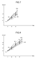
FIG. 7 is a diagram for explaining the second method for compression of time-series data. -
FIG. 8 is a diagram for explaining the second method for compression of time-series data. -
FIG. 9 is a diagram for explaining the second method for compression of time-series data. -
FIG. 10 is a diagram for explaining an example of a method for compression of time-series data according to the first embodiment. -
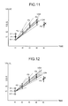
FIG. 11 is a diagram for explaining an example of the method for compression of time-series data according to the first embodiment. -
FIG. 12 is a diagram for explaining an example of the method for compression of time-series data according to the first embodiment. -
FIG. 13 is a diagram for explaining an example of the method for compression of time-series data according to the first embodiment. -
FIG. 14 is a flowchart for explaining an overall flow of a data compression operation according to the first embodiment. -
FIG. 15 is a diagram for explaining an example of post-processing. -
FIG. 16 is a block diagram illustrating an exemplary configuration of a data compression device according to a second embodiment. -
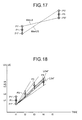
FIG. 17 is a diagram for explaining an example of a minimum lower limit slope and a maximum upper limit slope. -
FIG. 18 is a diagram illustrating an example of an upper limit slope and a lower limit slope. -
FIG. 19 is a diagram illustrating an example of the upper limit slope and the lower limit slope. -
FIG. 20 is a diagram illustrating an example of the upper limit slope and the lower limit slope. -
FIG. 21 is a flowchart for explaining an overall flow of a data compression operation according to the second embodiment. -
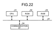
FIG. 22 is an explanatory diagram illustrating a hardware configuration of the data compression device according to the first embodiment or the second embodiment. Description of Embodiments - Preferred embodiments of a data compression device according to the present invention are described below in detail with reference to the accompanying drawings.
- As described above, according to the Swinging Door algorithm or the like, a single starting point is set and linear approximation is performed in order to compress time-series data. In a data compression device according to a first embodiment, a plurality of starting points (starting point candidates) is set, and time-series data is compressed using such a starting point candidate which enables achieving compression in a more efficient manner.
- Herein, the explanation is given about the terms used in the embodiments.
- Time-series data points to a series of values (a point data string) obtained by observing or measuring temporal changes of a particular phenomenon. Usually, time-series data is measured at predetermined time intervals. Examples of time-series data include share prices and sensor values of an in-plant installation. For example, regarding a number of devices constituting an in-plant installation; a series of values of humidity, a series of values of vibrations, or a series of values of control setting can be said to form a single piece of time-series data.
- A time-series database is created by compiling time-series data. As a time-series database, a large volume of time-series data is stored in chronological order in a memory of a computer or in an external memory device (a hard disk).
- A data item which is the smallest unit of data storage is called a tag. A tag is made of a data value, a time stamp, a data status, and the like. The data that is to be collected has types such as operating data which is input from a control system, computational data which is obtained by implementing an online computation function, data which is manually input by an operator, and interface data which is input from other systems.
- In a time-series database, generally, there are several thousands to several tens of thousands of tags. The data storage period for each tag ranges from one year to several years. As far as the data collection cycle is concerned, although it is dependent on the real-time property of the concerned system (such as an in-plant installation); it ranges from a few seconds to one minute as a rough indication.
- If it is assumed that the collected data is stored without any modification, then a time-series database needs to have the database capacity of about 10 GB (gigabytes) to 10 TB (terabytes). If the database capacity is increased to that extent, then it is bound to cause deterioration in the retrieval performance.
- In that regard, for example, in an in-plant installation, a technology of data compression is implemented by making use of the property that, during stable operations, the operating data undergoes only a small change. In an in-plant installation, it is estimated that the behavior of the original data can be understood by referring to compressed data having the compression ratio of 1:20.
- In this way, since a time-series database needs a large-capacity memory area; there has been a demand for a method which would enable achieving compression of time-series data in a more efficient manner.
- Given below is the explanation of a data compression device according to a first embodiment.
FIG. 1 is a block diagram illustrating an exemplary configuration of adata compression device 100 according to the first embodiment. As illustrated inFIG. 1 , thedata compression device 100 includes a receivingunit 101, a registeringunit 110, a searchingunit 114, and amemory unit 121. - The receiving
unit 101, the registeringunit 110, and the searchingunit 114 can be implemented, for example, by executing a program in a processor such as a CPU (Central Processing Unit), that is, can be implemented using software; or can be implemented using hardware such as an IC (Integrated Circuit); or can be implemented using a combination of software and hardware. - The
memory unit 121 is used to store a variety of data. For example, thememory unit 121 is used to store time-series data that has been compressed by acompressing unit 113. Thememory unit 121 can be configured with any commonly-used memory medium such as an HDD (Hard Disk Drive), an optical disk, a memory card, and a RAM (Random Access Memory). - The receiving
unit 101 receives processing requests and data that are input from external devices such as client devices. A processing request points to, for example, a time-series data registration request or a time-series data search request. In the case of a registration request, the receivingunit 101 receives a plurality of pieces of input data (point data of time-series data) that is input in chronological order. Alternatively, the receivingunit 101 can also receive pieces of point data that are input in real time. For example, the receivingunit 101 stores the pieces of point data, which are input in real time, in thememory unit 121. Still alternatively, the receivingunit 101 can receive pieces of point data in chronological order from the time-series data stored in thememory unit 121. In the case of receiving input of the time-series data from thememory unit 121, the configuration can be such that the receivingunit 101 goes back in time to a particular timing serving as the starting point, that is, receives the pieces of point data in a sequential manner starting from an earlier timing. - The registering
unit 110 performs, based on an allowable error, an operation (a compression operation) of thinning a piece of point data from a series of point data that is input; and registers the post-thinning point data as time-series data in thememory unit 121. Regarding an algorithm for thinning a piece of point data using starting point candidates and using other pieces of point data; it is possible to use any one of the conventional algorithms such as the Swinging Door algorithm. Meanwhile, the registeringunit 110 includes agenerating unit 111, a selectingunit 112, and thecompressing unit 113. - The generating
unit 111 generates a plurality of starting point candidates that represents data having an error within a predetermined threshold value with respect to starting point data, which is the point data at a particular timing (a first timing). - The selecting
unit 112 selects, from among the starting point candidates, such a starting point candidate which enables achieving compression of the time-series data in a more efficient manner. For example, the selectingunit 112 selects, from among the starting point candidates, such a starting point candidate which has a greater number of pieces of point data (intermediate data) that is approximated using the concerned starting point candidate and using end point data, which is input at a different timing (a second timing) than the timing of the starting point data, in such a way that the error is within a predetermined threshold value. - Then, the compressing
unit 113 outputs the selected starting point candidate and the end point data as a piece of post-compression time-series data (output data). The compressingunit 113 stores, for example, the post-compression time-series data in thememory unit 121 in a sequential manner. Alternatively, the compressingunit 113 can also store at once a plurality of pieces of post-compression time-series in thememory unit 121. - The searching
unit 114 searches for the time-series data that is stored in thememory unit 121. For example, when a start timing, an end timing, and a sampling interval are specified; the searchingunit 114 searches, at the specified sampling interval, the time-series database for a point data series in a section from the start timing to the end timing. Since there are times when the registeringunit 110 performs point data thinning, sometimes point data may not be retrieved at the specified sampling interval. In such a case, the searchingunit 114 interpolates the point data using, for example, the linear interpolation method that is an example of the methods to perform interpolation between two points. If (xs, ys) represents the start point and if (xe, ye) represents the end point; then, with respect to an arbitrary x present on the straight line joining the start point and the end point, the value of y can be obtained using Equation (1). Meanwhile, xe ≠ xs is satisfied.
- Given below is the explanation of a specific example of a data compression operation performed according to the first embodiment.
FIG. 2 is a diagram illustrating an example of time-series data. InFIG. 2 is illustrated time-series data that contains five pieces of point data, namely, P1, P2, P3, P4, and P5. As described below, point data represents, for example, a combination of a timing (Time) and a value (Value). Herein, it is not always necessary to have a constant time interval.
P1<t1, v1>, P2<t2, v2>, P3<t3, v3>, P4<t4, v4>, and P5<t5, v5> are present. Moreover, t1 < t2 < t3 < t4 < t5 is satisfied. -
FIG. 3 to FIG. 5 are diagrams for explaining a first method for compression of time-series data. As illustrated inFIG. 3 , α represents the allowable error specified in advance. Moreover, P1 is set as the starting point data. When P2 is input as a new piece of point data, the registeringunit 110 obtains an upper limit slope US2 and a lower limit slope LS2 with respect to P2. - Firstly, with respect to the value <t2, v2> of P2, the registering
unit 110 obtains two piece of point data P2'<t2, v2+α> and P2" <t2, v2-α> that have the largest allowable error at the timing t2. The upper limit slope US2 represents the tilt of the line segment from P1 to P2', and can be obtained as US2 = (v2 + α - V1)/(t2 - t1). The lower limit slope LS2 represents the tilt of the line segment from P1 to P2", and can be obtained as LS2 = (v2 - α - v1) / (t2 - t1). - As illustrated in
FIG. 4 , when P3 is input as a new piece of point data, the registeringunit 110 obtains an upper limit slope US3 and a lower limit slope LS3 with respect to P3. The upper limit slope US3 represents the tilt of the line segment from P1 to P3', and can be obtained as US3 = (v3 + α - V1)/(t3 - t1). The lower limit slope LS3 represents the tilt of the line segment from P1 to P3", and can be obtained as LS3 = (v3 - α - v1)/(t3 - t1). - If the upper limit slope US3 up to P3 is smaller than the upper limit slope US2 up to P2 and if the lower limit slope LS3 up to P3 is greater than the lower limit slope LS2 up to P2, then the older piece of point data P2 is subjected to thinning.
- As illustrated in
FIG. 5 , when P4 is input as a new piece of point data, the registeringunit 110 obtains an upper limit slope US4 and a lower limit slope LS4 with respect to P4. If the upper limit slope US4 up to P4 is smaller than the upper limit slope US3 up to P3 and if the lower limit slope LS4 up to P4 is greater than the lower limit slope LS3 up to P3, then the older piece of point data P3 is subjected to thinning. - However, in the example illustrated in
FIG. 5 , the lower limit slope LS4 up to P4 is smaller than the lower limit slope LS3 up to P3. As a result, P4 cannot be subjected to thinning, and P3 remains as the end point data. Thus, in the time-series database (in the memory unit 121), two pieces of point data P1 and P3 get archived. -
FIG. 6 to FIG. 9 are diagrams for explaining a second method for compression of time-series data. As illustrated inFIG. 6 , α represents the allowable error specified in advance. Moreover, P1 is set as the starting point data. When P2 is input as a new piece of point data, the registeringunit 110 obtains the upper limit slope US2 and the lower limit slope LS2 with respect to P2. Herein, the registeringunit 110 can obtain the upper limit slope US2 and the lower limit slope LS2 by implementing a method identical to the method explained with reference toFIG. 3 . However, from the first method explained with reference toFIG. 3 , the second method differs in the way that an allowable error range can be obtained. InFIG. 6 , a portion between oblique lines represents the allowable error range with respect to P2. Herein, the allowable error range with respect to P2 is identified by two parameters, namely, the upper limit slope US2 and the lower limit slope LS2. - As illustrated in
FIG. 7 , when P3 is input as a new piece of point data, the registeringunit 110 obtains a provisional upper limit slope US3 and a provisional lower limit slope LS3 with respect to P3. The allowable error range with respect to P3 is identified by two parameters, namely, the upper limit slope US3 and the lower limit slope LS3. The registeringunit 110 sets, as the allowable error range with respect to P3, the overlapping portion between the allowable error range with respect to P2 and a provisional allowable error range with respect to P3. - The registering
unit 110 calculates, for example, "LS2>US3 ∨ LS3>US2". If that value is true, then the registeringunit 110 determines that the allowable error range with respect to P2 does not overlap with the provisional allowable error range with respect to P3. However, if that value is false, then the registeringunit 110 determines that the allowable error range with respect to P2 overlaps with the provisional allowable error range with respect to P3. - In the example illustrated in
FIG. 7 , since there is overlapping of the two allowable error ranges, the registeringunit 110 obtains the allowable error range with respect to P3 in the following manner. Min(A, B) is a function that returns the smaller value from among A and B. Max(A, B) is a function that returns the greater value from among A and B. Herein, P2 is subjected to thinning.

- As illustrated in
FIG. 8 , when P4 is input as a new piece of point data, the registeringunit 110 obtains a provisional upper limit slope US4 and a provisional lower limit slope LS4 with respect to P4. Then, in an identical manner to the explanation with reference toFIG. 7 , the registeringunit 110 determines whether or not the allowable error range with respect to P3 overlaps with the provisional allowable error range with respect to P4. In the example illustrated inFIG. 8 , since there is overlapping of the two allowable error ranges, the registeringunit 110 obtains the allowable error range with respect to P3 in the following manner. Herein, P3 is subjected to thinning.


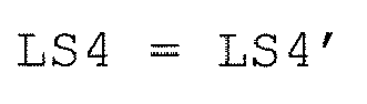
- As illustrated in
FIG. 9 , when P5 is input as a new piece of point data, the registeringunit 110 obtains a provisional upper limit slope US5 and a provisional lower limit slope LS5 with respect to P5. Then, the registeringunit 110 calculates "LS4>US5 ∨ LS5>US4". In the example illustrated inFIG. 9 , since that value is true, the registeringunit 110 determines that the allowable error range with respect to P4 does not overlap with the allowable error range with respect to P5. As a result, P5 cannot be subjected to thinning, and P4 remains as the end point data. Thus, in the time-series database (in the memory unit 121), two pieces of point data P1 and P4 get archived. - As far as the algorithm in the method for compression is concerned, the registering
unit 110 can implement any one of the first method and the second method. Alternatively, the registeringunit 110 can implement any other algorithm too. Conventionally, any such algorithm is implemented by setting a single starting point. However, in contrast, the registeringunit 110 sets a plurality of starting points (starting point candidates) and implements an abovementioned algorithm with respect to a plurality of starting point candidates. -
FIG. 10 to FIG. 13 are diagrams for explaining an example of a method for compression of time-series data according to the first embodiment. In the first and second methods for compression, only a single point serves as the starting point at t1. In contrast, in the first embodiment, a plurality of starting point candidates is set, and thinning calculation is performed in parallel while treating each starting point candidate as the starting point. - If the number of starting points to be generated is set to three; then the
generating unit 111 generates, for example, P1<t1, v1>, P1'<t1, v1+α>, and P1" <t1, v1-α> as the starting point candidates. If the number of starting points to be generated is set to N; then thegenerating unit 111 generates, for example, <t1, v1+α>, <t1, v1+α×(1-2/(N-1))×1>, <t1, v1+α×(1-2/(N-1))×2>, ..., <t1, v1>, ..., and <t1, v1-α> as the starting point candidates. However, the method of generating the starting point candidates is not limited to this method. That is, as long as a value is within the range of the allowable error α centered on the starting point data, any piece of point data can be treated as a starting point candidate. - Explained below with reference to
FIG. 11 to FIG. 13 is an example of a case in which thinning calculation according to the second method for compression is performed. As illustrated inFIG. 11 , P1<t1, v1>, P1'<t1, v1+α>, and P1" <t1, v1-α> serve as the starting point candidates. InFIG. 11 is illustrated an example in which thinning is performed with P1" <t1, v1-α> serving as the starting point from among the starting point candidates. As illustrated inFIG. 11 , when P1" <t1, v1-α> is treated as the starting point, thinning can be performed up to P2, P3, and P4. However, it is not possible to perform thinning at P5. - In
FIG. 12 is illustrated an example in which thinning is performed with P1<t1, v1> serving as the starting point. As illustrated inFIG. 12 , when P1<t1, v1> is treated as the starting point, thinning can be performed up to P2, P3, and P4. However, it is not possible to perform thinning at P5. - In
FIG. 13 is illustrated an example in which thinning is performed with P1'<t1, v1+α> serving as the starting point. As illustrated inFIG. 13 , when P1'<t1, v1+α> is treated as the starting point, thinning can be performed up to P2, P3, P4, and P5. - In this way, in the first and second methods for compression, only a single point serves as the starting point at t1. In contrast, in the first embodiment, a plurality of starting point candidates is set, and thinning calculation is performed in parallel while treating each starting point candidate as the starting point. For that reason, in the examples given above, when a single starting point is present, thinning is possible only up to P4 at a maximum. In contrast, in the method according to the first embodiment, thinning can be performed up to P5. In this way, in the method according to the first embodiment, at the same allowable error, a higher compression ratio is achieved.
- Explained below with reference to
FIG. 14 is a data compression operation performed in thedata compression device 100 configured in the abovementioned manner according to the first embodiment.FIG. 14 is a flowchart for explaining an overall flow of the data compression operation according to the first embodiment.FIG. 14 represents an example of the case in which the second method for compression described above is implemented. - Firstly, the selecting
unit 112 selects the starting point data (Step S101). For example, when pieces of time-series data are input in real time; the selectingunit 112 can select, as the starting point data, either the piece of point data that is input at the start or the piece of point data that is input after completion of a thinning operation with respect to already-input pieces of point data. Alternatively, when pieces of point data are sequentially input from already-stored time-series data; the selectingunit 112 can select, as the starting point data, either the piece of point data that is input at the start or the piece of point data that is input after completion of a thinning operation with respect to already-input pieces of point data. - Then, the generating
unit 111 generates a plurality of starting point candidates that has an error within the allowable error with respect to the selected starting point data (Step S102). - Subsequently, the selecting
unit 112 selects next point data (Step S103). Herein, the next point data indicates a piece of point data that, with the timing of input of the starting point data (the first timing) serving as the reference timing, is sequentially input at each successive timing (a second timing). The next point data is selected by sequentially shifting the timing until thinning cannot be performed any more. In the following explanation, the next point data selected at the previous timing is called former next-point data. Thus, the former next-point data at the timing at which thinning cannot be performed any more is equivalent to the end point data. The pieces of point data selected prior to the former next-point data are equivalent to the intermediate data input in between the starting point data and the end point data (the former next-point data) present in the end. - As described above, the timing of input of the next point data can be a timing before or after the timing of input of the starting point data. Moreover, for example, when the pieces of point data are sequentially input from the already-stored time-series data, there can be a situation in which the starting point data selected at Step S101 becomes the last piece of point data, and the next point data cannot be selected (obtained). In such a case, although not illustrated in
FIG. 14 , the registeringunit 110 can end the data compression operation. Meanwhile, when the pieces of point data are input in real time, the selectingunit 112 can hold back from performing the operation at Step S103 till the next piece of point data (the next point data) is obtained. - Subsequently, the selecting
unit 112 selects a single starting point candidate from among the starting point candidates that are generated (Step S104). Then, the selectingunit 112 determines whether or not the selected starting point candidate has been disabled (Step S105). Herein, disabling means exempting from the subsequent operations such a starting point candidate at which thinning cannot be performed using the next point data that has been selected. For example, a starting point candidate at which thinning could not be performed during operations for the former next-point data is disabled while processing the former next-point data (Step S109 described later). In this way, at Step S105, it is determined whether the selected starting point candidate has been disabled during the operations performed till the previous step. - If the selected starting point candidate has been disabled (Yes at Step S105); then the selecting
unit 112 returns to the operation at Step S104, selects the next starting point candidate, and repeats the operations. On the other hand, if the selected starting point candidate has not been disabled (No at Step S105), then the selectingunit 112 calculates the upper limit slope and the lower limit slope from the selected starting point candidate up to the next point data (Step S106). Then, the selectingunit 112 compares the calculated upper limit slope and the calculated lower limit slope with the upper limit slope and the lower limit slope calculated with respect to the former next-point data (Step S107). For example, the selectingunit 112 determines whether or not the allowable error range identified by the upper limit slope and the lower limit slope of the former next-point data overlaps with the allowable error range identified by the upper limit slope and the lower limit slope of the next point data. - Thus, the selecting
unit 112 determines whether or not the two allowable error ranges overlap with each other (Step S108). If the two allowable error ranges do not overlap with each other (No at Step S108), the selectingunit 112 disables the currently-selected starting point candidate (Step S109). Then, the selectingunit 112 returns to the operation at Step S104. On the other hand, if the two allowable error ranges overlap with each other (Yes at Step S108), then the selectingunit 112 updates the upper limit slope and the lower limit slope from the starting point candidate with the upper limit slope and the lower limit slope calculated with respect to the existing next point data (Step S110). - Subsequently, the selecting
unit 112 determines whether or not all starting point candidates have been processed (Step S111). If all starting point candidates are yet to be processed (No at Step S111), the selectingunit 112 returns to the operation at Step S104 and repeats the operations. When all starting point candidates are processed (Yes at Step S111), the selectingunit 112 determines whether or not all starting point candidates have been disabled (Step S112). If all starting point candidates are yet to be disabled (No at Step S112), then the selectingunit 112 selects the point data at the next successive timing as the new next point data, and repeats the operations (Step S103). - When all starting point candidates are disabled (Yes at Step S112), the selecting
unit 112 selects the starting point candidate that is disabled in the last instance (Step S113). As a result of such operations, the selectingunit 112 becomes able to select the starting point candidate at which a greater number of pieces of point data (intermediate data) are approximated to have the error within the allowable error. - Meanwhile, if there is a plurality of starting point candidates that is disabled in the last instance, the selecting
unit 112 selects one of those starting point candidates. Herein, from among a plurality of starting point candidates that is disabled in the last instance, the selectingunit 112 selects the starting point candidate having a closer value to the starting point data. - Depending on the selected starting point candidate, the compressing
unit 113 performs post-processing for the purpose of correcting the value of the end point data (the former next-point data) (Step S114). Alternatively, the configuration can be such that the end point data is output without performing post-processing. -
FIG. 15 is a diagram for explaining an example of post-processing. InFIG. 15 is illustrated an example in which thinning cannot be performed when P5 serves as the next point data, and P4 remains as the former next-point data (the end point data). Herein, it is assumed that P1" is selected as the starting point candidate. The compressingunit 113 obtains the average slope of the upper limit slope and the lower limit slope of the former next-point data. Then, the compressingunit 113 treats the straight line having the tilt equal to the abovementioned average slope as the approximated data string, and obtains the value of the data string at t4. Subsequently, the compressingunit 113 sets the value as the value (P4') of the corrected end point data. Then, the compressingunit 113 stores the selected starting point candidate and the corrected end point data in thememory unit 121. - Returning to the explanation with reference to
FIG. 14 , the selectingunit 112 determines whether or not all input data has been processed (Step S115). If all input data is yet to be processed (No at Step S115), then the selectingunit 112 selects the next piece of point data as the new starting point data (Step S101) and repeats the subsequent operations. For example, the next point data present at the time when all starting point candidates are disabled is selected as the new starting point data. - In this way, in the data compression according to the first embodiment, a plurality of starting point candidates is set, and thinning calculation is performed while treating each starting point candidate as the starting point. Then, a starting point candidate is selected at which a greater volume of data can be subjected to thinning, and the data subjected to thinning using the selected starting point candidate is output as the resultant data of compression. As a result, it becomes possible to enhance the compression ratio of the time-series data.
- As a result of implementing the method according to the first embodiment, although an enhancement in the compression ratio is achieved, there also occurs an increase in the amount of calculation because of the thinning calculation performed in parallel among a plurality of starting point candidates. In that regard, in a data compression device according to a second embodiment, an operation (filtering) for skipping the thinning calculation is also performed.
-
FIG. 16 is a block diagram illustrating an exemplary configuration of a data compression device 100-2 according to the second embodiment. As illustrated inFIG. 16 , the data compression device 100-2 includes the receivingunit 101, a registering unit 110-2, the searchingunit 114, and thememory unit 121. - In the second embodiment, a selecting unit 112-2 of the registering unit 110-2 has different functions than the first embodiment. Apart from that, the configuration and the functions are identical to
FIG. 1 that is the block diagram illustrating a configuration of thedata compression device 100 according to the first embodiment. Hence, the configuration and the functions are referred to by the same reference numerals, and the explanation thereof is not repeated. - The selecting unit 112-2 not only has the functions of the selecting
unit 112 but also has an additional function of filtering. The selecting unit 112-2 determines, prior to performing operations with respect to each starting point candidate, whether a range that is approximated to be within the allowable error in the former next-point data and a range that is approximated to be within the allowable error in the next point data satisfy a predetermined condition. If the condition is satisfied, then the selecting unit 112-2 determines that approximation cannot be done to be within the allowable error in the next point data, and does not perform a determination operation with respect to the starting point candidates. - For example, the selecting unit 112-2 compares the minimum lower limit slope and the maximum upper limit slope of the former next-point data with the minimum lower limit slope and the maximum upper limit slope of the (existing) next point data, and determines whether a predetermined condition is satisfied. Then, the selecting unit 112-2 obtains a determination value (such as true or false) indicating whether or not the condition is satisfied, and skips operations with respect to the starting point candidates according to the determination value.
- The minimum lower limit slope represents the minimum value from among the slopes (slopes) between the starting point candidates and a value obtained by subtracting the allowable error from the point data. The maximum upper limit slope represents the maximum value from among the slopes (slopes) between the starting point candidates and a value obtained by adding the allowable error to the point data.
FIG. 17 is a diagram for explaining an example of a minimum lower limit slope MinLS and a maximum upper limit slope MaxUS. - With respect to P5, there are three upper limit slopes (referred to as US5, US5', and US5") having the starting points P1, P1', and P1", respectively. The maximum upper limit slope MaxUS indicates the maximum value from among the three upper limit slopes. MaxUS = Max(US5, US5', US5")
- In an identical manner, with respect to P5, there are three lower limit slopes (referred to as LS5, LS5', and LS5") having the starting points P1, P1', and P1", respectively. The minimum upper limit slope MinLS indicates the minimum value from among the three upper limit slopes.

-
FIG. 18 to FIG. 20 are diagrams illustrating examples of the upper limit slope and the lower limit slope with respect to P4. InFIG. 18 is illustrated an upper limit slope US4" and a lower limit slope LS4" in the case when P1" serves as the starting point. InFIG. 19 is illustrated the upper limit slope US4 and the lower limit slope LS4 in the case when P1 serves as the starting point. InFIG. 20 is illustrated the upper limit slope US4' and the lower limit slope LS4' in the case when P1' serves as the starting point. - With respect to P4 too, the maximum upper limit slope and the minimum lower limit slope can be obtained in the following manner.


- Herein, regarding P4 (the former next-point data), it is assumed that MinLS4 represents the minimum lower limit slope and MaxUS4 represents the maximum upper limit slope. Moreover, regarding P5 (the former next-point data), it is assumed that MinLS5 represents the minimum lower limit slope and MaxUS5 represents the maximum upper limit slope. The selecting unit 112-2 compares MinLS4, MaxUS4, MinLS5, and MaxUS5 according to the following condition, and calculates a determination value that indicates whether or not the condition is satisfied.

- This condition indicates that "either the maximum upper limit slope at P4 is smaller than the minimum lower limit slope at P5 or the minimum lower limit slope at P4 is greater than the maximum upper slope at P5". In such a case, it is clear that the allowable error range with respect to P4 does not overlap with the allowable error range with respect to P5. For that reason, it becomes possible to skip the operation of calculating the slope for each starting point candidate, and to continue with the operations assuming that all starting point candidates have been disabled. That is, it becomes possible to reduce the amount of calculation by means of avoiding unnecessary calculation.
- Explained below with reference to
FIG. 21 is a data compression operation performed in the data compression device 100-2 configured in the abovementioned manner according to the second embodiment.FIG. 21 is a flowchart for explaining an overall flow of the data compression operation according to the second embodiment. - The operations performed from Step S201 to Step S203 are identical to the operations performed from Step S101 to Step S103 in the
data compression device 100 according to the first embodiment. Hence, that explanation is not repeated. - In the second embodiment, the selecting unit 112-2 calculates the determination value mentioned above (Step S204). Then, the selecting unit 112-2 determines whether or not the determination value is true (Step S205). If the determination value is false (No at Step S205), then the selecting unit 112-2 performs operations with respect to each starting point candidate (Step S206 to Step S214). Herein, the operations performed from Step S206 to Step S214 are identical to the operations performed from Step S104 to Step S112 according to the first embodiment. Hence, that explanation is repeated.
- On the other hand, if the determination value is true (Yes at Step S205), then the selecting unit 112-2 proceeds to the operation at Step S215 without performing the operations from Step S206 to Step S214. The operations performed from Step S215 to Step S217 are identical to the operations performed from Step S113 to Step S115 according to the first embodiment. Hence, that explanation is not repeated.
- In this way, in the data compression device according to the second embodiment, filtering is additionally performed with the aim of skipping the thinning calculation. As a result, it becomes possible to hold down the increase in the amount of calculation attributed to the use of a plurality of starting points.
- Explained below with reference to
FIG. 22 is a hardware configuration of the data compression device according to the first embodiment or the second embodiment.FIG. 22 is an explanatory diagram illustrating a hardware configuration of the data compression device according to the first embodiment or the second embodiment. - The data compression device according to the first embodiment or the second embodiment includes a control device such as a CPU (Central Processing Unit) 51; memory devices such as a ROM (Read Only Memory) 52 and a RAM (Random Access Memory) 53; a communication I/
F 54 that performs communication by establishing connection with a network; and abus 61 that interconnects the other constituent elements. - Meanwhile, a data compression program executed in the data compression device according to the first embodiment or the second embodiment is stored in advance in the
ROM 52 or the like. - Alternatively, the data compression program executed in the data compression device according to the first embodiment or the second embodiment can be recorded in the form of an installable or an executable file in a computer-readable recording medium such as a CD-ROM (Compact Disk Read Only Memory), a flexible disk (FD), a CD-R (Compact Read Recordable), or a DVD (Digital Versatile Disk).
- Still alternatively, the data compression program executed in the data compression device according to the first embodiment or the second embodiment can be saved as a downloadable file on a computer connected to the Internet or can be made available for distribution through a network such as the Internet.
- The data compression program executed in the data compression device according to the first embodiment or the second embodiment can cause a computer to function as each constituent element of the data compression device described above. In that computer, the
CPU 51 can read the data compression program from a computer-readable recording medium in a main memory device and then execute the data compression program. - Although the invention has been described with respect to specific embodiments for a complete and clear disclosure, the appended claims are not to be thus limited but are to be construed as embodying all modifications and alternative constructions that may occur to one skilled in the art that fairly fall within the basic teaching herein set forth. For example, it is possible to delete some of the constituent elements described in the embodiments. Alternatively, it is possible to combine the constituent elements across different embodiments.
-
- 100 data compression device
- 101 receiving unit
- 110 registering unit
- 111 generating unit
- 112 selecting unit
- 113 compressing unit
- 114 searching unit
- 121 memory unit
Claims (10)
- A data compression device comprising:a receiving unit configured to receive a plurality of pieces of input data which is input in chronological order;a generating unit configured to generate a plurality of starting point candidates which represents data having an error within a threshold value with respect to starting point data, the starting point data being the input data input at a first timing;a selecting unit configured to refer to the starting point candidates, end point data which is the input data input at a second timing, and intermediate data which is the input data input at a timing in between the first timing and the second timing, and to select, from among the starting point candidates, the starting point candidate which, as compared to other of the starting point candidates, has a greater number of pieces of the intermediate data approximated using the starting point candidate and using the end point data in such a way that an error is within the threshold value; anda compressing unit configured to output the selected starting point candidate and the end point data as output data obtained by compressing the starting point data, the intermediate data, and the end point data.
- The data compression device according to claim 1, wherein, for each of the starting point candidates, the selecting unit repeatedly performs, by changing the second timing, a determination operation for determining whether or not the intermediate data is included in a range approximated using the starting point candidate and using the end point data in such a way that an error is within the threshold value, and selects the starting point candidate which, as compared to other of the starting point candidates, has a greater number of pieces of the intermediate data at the time when the intermediate data is last determined to be within approximated range.
- The data compression device according to claim 2, wherein, when the second timing is changed, the selecting unit determines whether or not a range approximated to have an error within the threshold value at a pre-change timing and a range approximated to have an error within the threshold value at a post-change timing satisfy a predetermined condition, and, when the predetermined condition is satisfied, determines that, at a post-change timing, the intermediate data is not included in a range approximated to be within the threshold value.
- The data compression device according to claim 3, wherein, at a pre-change timing as well as at a post-change timing, the selecting unit calculates a minimum lower limit slope which is a minimum value from among tilts of line segments from the starting point candidates to data having an error within the threshold value, calculates a maximum upper limit slope, which is a maximum value from among the tilts of the line segments, and determines whether or not the minimum lower limit slope and the maximum upper limit slope at a pre-change timing as well as the minimum lower limit slope and the maximum upper limit slope at a post-change timing satisfy the condition.
- The data compression device according to claim 1, wherein, when a plurality of the starting point candidate has the same number of pieces of the intermediate data, the selecting unit selects, from among a plurality of the starting point candidates having the same number of pieces of the intermediate data, the starting point candidate having a smaller difference with the starting point data.
- The data compression device according to claim 1, wherein, as the output data, the compressing unit outputs the selected starting point candidate and the end point data corrected according to the selected starting point candidate.
- The data compression device according to claim 1, wherein, from among the starting point candidates, the selecting unit selects the starting point candidate which, as compared to other of the starting point candidates, has a greater number of pieces of the intermediate data included in an allowable error range decided using the starting point candidate and using data having an error within the threshold value with respect to the end point data.
- A data compression method comprising:a receiving step that includes receiving a plurality of pieces of input data which is input in chronological order;a generating step that includes generating a plurality of starting point candidates which represents data having an error within a threshold value with respect to starting point data, the starting point data being the input data input at a first timing;a selecting step that includes referring to the starting point candidates, end point data which is the input data input at a second timing, intermediate data which is the input data input at a timing in between the first timing and the second timing, and selecting, from among the starting point candidates, the starting point candidate which, as compared to other of the starting point candidates, has a greater number of pieces of the intermediate data approximated using the starting point candidate and using the end point data in such a way that an error is within the threshold value; anda compressing step that includes outputting the selected starting point candidate and the end point data as output data obtained by compressing the starting point data, the intermediate data, and the end point data.
- A data compression method for compressing time-series data that represents a series of point data containing timings and values obtained by measuring temporal changes of a phenomenon, the data compression method comprising:a step for setting point data at a first timing as a starting point;a step for generating a plurality of starting point candidates having an error within a threshold value with respect to the starting point;a step for setting point data obtained at a timing later than the first timing as a point of interest;a step for calculating, for each of the starting point candidates, an upper limit slope and a lower limit slope based on a range of error with respect to the point of interest;a step for updating, when an allowable error range specified by the calculated upper limit slope and the calculated lower limit slope overlaps with an allowable error range specified by an upper limit slope and a lower limit slope that are calculated with respect to a point of interest at previous timing, the upper limit slope and the lower limit slope and thinning the point of interest at the previous timing;a step for disabling, when an allowable error range specified by the calculated upper limit slope and the calculated lower limit slope does not overlap with an allowable error range specified by an upper limit slope and a lower limit slope that are calculated with respect to a point of interest at previous timing, the starting point candidate; anda step for continuing, when the starting point candidate that is not yet disabled is remaining, a thinning operation in which, with respect to the starting point candidate that is remaining, point data obtained at next timing is set as a point of interest.
- A program that causes a computer to function as:a receiving unit configured to receive a plurality of pieces of input data which is input in chronological order;a generating unit configured to generate a plurality of starting point candidates which represents data having an error within a threshold value with respect to starting point data, the starting point data being the input data input at a first timing;a selecting unit configured to refer to the starting point candidates, end point data which is the input data input at a second timing, intermediate data which is the input data input at a timing in between the first timing and the second timing, and that selects, from among the starting point candidates, the starting point candidate which, as compared to other of the starting point candidates, has a greater number of pieces of the intermediate data approximated using the starting point candidate and the end point data in such a way that an error is within the threshold value; anda compressing unit configured to output, to a memory unit, the selected starting point candidate and the end point data as output data obtained by compressing the starting point data, the intermediate data, and the end point data.
Applications Claiming Priority (1)
| Application Number | Priority Date | Filing Date | Title |
|---|---|---|---|
| PCT/JP2013/052245 WO2014118954A1 (en) | 2013-01-31 | 2013-01-31 | Data compression device, data compression method, and program |
Publications (3)
| Publication Number | Publication Date |
|---|---|
| EP2953266A1 true EP2953266A1 (en) | 2015-12-09 |
| EP2953266A4 EP2953266A4 (en) | 2016-08-31 |
| EP2953266B1 EP2953266B1 (en) | 2019-09-25 |
Family
ID=51224109
Family Applications (1)
| Application Number | Title | Priority Date | Filing Date |
|---|---|---|---|
| EP13836184.5A Active EP2953266B1 (en) | 2013-01-31 | 2013-01-31 | Data compression device, data compression method, and program |
Country Status (6)
| Country | Link |
|---|---|
| US (1) | US9838032B2 (en) |
| EP (1) | EP2953266B1 (en) |
| JP (1) | JP5622967B1 (en) |
| CN (1) | CN104160629B (en) |
| AU (1) | AU2013376200B2 (en) |
| WO (1) | WO2014118954A1 (en) |
Families Citing this family (4)
| Publication number | Priority date | Publication date | Assignee | Title |
|---|---|---|---|---|
| CN107807271B (en) * | 2017-09-29 | 2021-04-16 | 中国电力科学研究院 | A method and system for automatically compressing overvoltage monitoring data |
| CN108667463B (en) * | 2018-03-27 | 2021-11-02 | 江苏中科羿链通信技术有限公司 | Monitoring data compression method |
| CN114142865B (en) * | 2021-10-28 | 2024-11-19 | 上海麦杰科技股份有限公司 | A single-point lossy compression method and device for industrial Internet of Things real-time database |
| CN114142864B (en) * | 2021-10-28 | 2025-11-14 | 上海麦杰科技股份有限公司 | A method and apparatus for lossy concurrent compression of real-time databases in the industrial Internet of Things |
Family Cites Families (13)
| Publication number | Priority date | Publication date | Assignee | Title |
|---|---|---|---|---|
| US4669097A (en) * | 1985-10-21 | 1987-05-26 | The Foxboro Company | Data compression for display and storage |
| EP0407935B1 (en) * | 1989-07-10 | 1999-10-06 | Hitachi, Ltd. | Document data processing apparatus using image data |
| US20050143981A1 (en) * | 2000-06-06 | 2005-06-30 | Yukio Koyanagi | Compressing method and apparatus, expanding method and apparatus, compression and expansion system, recorded medium, program |
| JP2003015734A (en) * | 2001-07-02 | 2003-01-17 | Toshiba Corp | Time series data compression method, time series data storage device and program |
| US7076402B2 (en) | 2004-09-28 | 2006-07-11 | General Electric Company | Critical aperture convergence filtering and systems and methods thereof |
| JP4719667B2 (en) | 2006-12-28 | 2011-07-06 | 日立オートモティブシステムズ株式会社 | Time series data compression method |
| JP5369041B2 (en) * | 2010-03-30 | 2013-12-18 | 富士フイルム株式会社 | Page description data processing apparatus, method and program |
| JP5458056B2 (en) * | 2010-05-28 | 2014-04-02 | 株式会社日立製作所 | Time series data compression method and compression apparatus |
| EP2410589B1 (en) | 2010-07-23 | 2013-10-09 | Grützediek, Ursula | Method for producing a TMR construction element |
| CA2749661C (en) * | 2010-08-20 | 2022-03-15 | Pratt & Whitney Canada Corp. | Method and system for generating a data set |
| CN102393855B (en) * | 2011-10-18 | 2013-07-31 | 国电南瑞科技股份有限公司 | Dynamic control method for loss compression ratio of process data |
| CN102510287B (en) * | 2011-11-03 | 2014-06-11 | 电子科技大学 | Method for rapidly compressing industrial real-time data |
| CN102664635B (en) * | 2012-03-06 | 2015-07-29 | 华中科技大学 | The self-adapting data compression method that a kind of precision is controlled |
-
2013
- 2013-01-31 AU AU2013376200A patent/AU2013376200B2/en active Active
- 2013-01-31 JP JP2014504111A patent/JP5622967B1/en active Active
- 2013-01-31 WO PCT/JP2013/052245 patent/WO2014118954A1/en not_active Ceased
- 2013-01-31 CN CN201380003042.4A patent/CN104160629B/en active Active
- 2013-01-31 EP EP13836184.5A patent/EP2953266B1/en active Active
-
2014
- 2014-03-13 US US14/208,061 patent/US9838032B2/en active Active
Also Published As
| Publication number | Publication date |
|---|---|
| WO2014118954A1 (en) | 2014-08-07 |
| AU2013376200A1 (en) | 2015-02-19 |
| EP2953266B1 (en) | 2019-09-25 |
| JP5622967B1 (en) | 2014-11-12 |
| JPWO2014118954A1 (en) | 2017-01-26 |
| US20140214781A1 (en) | 2014-07-31 |
| US9838032B2 (en) | 2017-12-05 |
| CN104160629A (en) | 2014-11-19 |
| AU2013376200B2 (en) | 2016-06-23 |
| CN104160629B (en) | 2017-09-01 |
| EP2953266A4 (en) | 2016-08-31 |
Similar Documents
| Publication | Publication Date | Title |
|---|---|---|
| CN114429641B (en) | Time sequence action detection method and device, storage medium and terminal | |
| US20090183037A1 (en) | Statistical processing apparatus capable of reducing storage space for storing statistical occurrence frequency data and a processing method therefor | |
| US11074237B2 (en) | Method and system to estimate the cardinality of sets and set operation results from single and multiple HyperLogLog sketches | |
| US20150278706A1 (en) | Method, Predictive Analytics System, and Computer Program Product for Performing Online and Offline Learning | |
| JP5493597B2 (en) | Search method and search system | |
| US20220164394A1 (en) | System and methods for faster processor comparisons of visual graph features | |
| CN111681049B (en) | User behavior processing method, storage medium and related equipment | |
| CN114579294B (en) | Container elastic scaling system that supports service load surge prediction in cloud-native environment | |
| JP5699715B2 (en) | Data storage device and data storage method | |
| EP2953266B1 (en) | Data compression device, data compression method, and program | |
| CN110727602A (en) | Coverage rate data processing method and device and storage medium | |
| CN106291764A (en) | Based on big data and the method for meteorological forecast of meteorologic analysis field and system | |
| JP2003015734A (en) | Time series data compression method, time series data storage device and program | |
| CN107783990B (en) | Data compression method and terminal | |
| CN111258968B (en) | Enterprise redundant data cleaning method and device and big data platform | |
| JP5469876B2 (en) | Behavior prediction apparatus and program | |
| JP6047476B2 (en) | SAMPLE DATA PROCESSING DEVICE, METHOD, AND PROGRAM | |
| KR102412843B1 (en) | Device and method for extracting sample graph from original graph having properties of original graph | |
| US12259890B2 (en) | Real-time signal discovery | |
| CN119378669B (en) | Heterogeneous platform data mining and retrieval and data analysis and processing method, device, equipment and medium | |
| CN113688278A (en) | Information processing method, device, electronic equipment and computer readable medium | |
| EP4478210A1 (en) | Real-time signal discovery | |
| WO2016180350A1 (en) | Intelligent management method for terminal desktop, terminal, and computer storage medium | |
| CN105512232A (en) | Data storage method and device | |
| CN119697047B (en) | Network element health assessment methods, devices, equipment and computer-readable storage media |
Legal Events
| Date | Code | Title | Description |
|---|---|---|---|
| PUAI | Public reference made under article 153(3) epc to a published international application that has entered the european phase |
Free format text: ORIGINAL CODE: 0009012 |
|
| 17P | Request for examination filed |
Effective date: 20140314 |
|
| AK | Designated contracting states |
Kind code of ref document: A1 Designated state(s): AL AT BE BG CH CY CZ DE DK EE ES FI FR GB GR HR HU IE IS IT LI LT LU LV MC MK MT NL NO PL PT RO RS SE SI SK SM TR |
|
| AX | Request for extension of the european patent |
Extension state: BA ME |
|
| DAX | Request for extension of the european patent (deleted) | ||
| A4 | Supplementary search report drawn up and despatched |
Effective date: 20160728 |
|
| RIC1 | Information provided on ipc code assigned before grant |
Ipc: H03M 7/30 20060101AFI20160722BHEP |
|
| STAA | Information on the status of an ep patent application or granted ep patent |
Free format text: STATUS: EXAMINATION IS IN PROGRESS |
|
| 17Q | First examination report despatched |
Effective date: 20180618 |
|
| GRAP | Despatch of communication of intention to grant a patent |
Free format text: ORIGINAL CODE: EPIDOSNIGR1 |
|
| STAA | Information on the status of an ep patent application or granted ep patent |
Free format text: STATUS: GRANT OF PATENT IS INTENDED |
|
| INTG | Intention to grant announced |
Effective date: 20190425 |
|
| GRAS | Grant fee paid |
Free format text: ORIGINAL CODE: EPIDOSNIGR3 |
|
| GRAA | (expected) grant |
Free format text: ORIGINAL CODE: 0009210 |
|
| STAA | Information on the status of an ep patent application or granted ep patent |
Free format text: STATUS: THE PATENT HAS BEEN GRANTED |
|
| AK | Designated contracting states |
Kind code of ref document: B1 Designated state(s): AL AT BE BG CH CY CZ DE DK EE ES FI FR GB GR HR HU IE IS IT LI LT LU LV MC MK MT NL NO PL PT RO RS SE SI SK SM TR |
|
| REG | Reference to a national code |
Ref country code: GB Ref legal event code: FG4D |
|
| REG | Reference to a national code |
Ref country code: CH Ref legal event code: EP |
|
| REG | Reference to a national code |
Ref country code: AT Ref legal event code: REF Ref document number: 1184807 Country of ref document: AT Kind code of ref document: T Effective date: 20191015 |
|
| REG | Reference to a national code |
Ref country code: IE Ref legal event code: FG4D |
|
| REG | Reference to a national code |
Ref country code: DE Ref legal event code: R096 Ref document number: 602013061054 Country of ref document: DE |
|
| REG | Reference to a national code |
Ref country code: NL Ref legal event code: MP Effective date: 20190925 |
|
| PG25 | Lapsed in a contracting state [announced via postgrant information from national office to epo] |
Ref country code: FI Free format text: LAPSE BECAUSE OF FAILURE TO SUBMIT A TRANSLATION OF THE DESCRIPTION OR TO PAY THE FEE WITHIN THE PRESCRIBED TIME-LIMIT Effective date: 20190925 Ref country code: HR Free format text: LAPSE BECAUSE OF FAILURE TO SUBMIT A TRANSLATION OF THE DESCRIPTION OR TO PAY THE FEE WITHIN THE PRESCRIBED TIME-LIMIT Effective date: 20190925 Ref country code: BG Free format text: LAPSE BECAUSE OF FAILURE TO SUBMIT A TRANSLATION OF THE DESCRIPTION OR TO PAY THE FEE WITHIN THE PRESCRIBED TIME-LIMIT Effective date: 20191225 Ref country code: NO Free format text: LAPSE BECAUSE OF FAILURE TO SUBMIT A TRANSLATION OF THE DESCRIPTION OR TO PAY THE FEE WITHIN THE PRESCRIBED TIME-LIMIT Effective date: 20191225 Ref country code: SE Free format text: LAPSE BECAUSE OF FAILURE TO SUBMIT A TRANSLATION OF THE DESCRIPTION OR TO PAY THE FEE WITHIN THE PRESCRIBED TIME-LIMIT Effective date: 20190925 Ref country code: LT Free format text: LAPSE BECAUSE OF FAILURE TO SUBMIT A TRANSLATION OF THE DESCRIPTION OR TO PAY THE FEE WITHIN THE PRESCRIBED TIME-LIMIT Effective date: 20190925 |
|
| REG | Reference to a national code |
Ref country code: LT Ref legal event code: MG4D |
|
| PG25 | Lapsed in a contracting state [announced via postgrant information from national office to epo] |
Ref country code: GR Free format text: LAPSE BECAUSE OF FAILURE TO SUBMIT A TRANSLATION OF THE DESCRIPTION OR TO PAY THE FEE WITHIN THE PRESCRIBED TIME-LIMIT Effective date: 20191226 Ref country code: LV Free format text: LAPSE BECAUSE OF FAILURE TO SUBMIT A TRANSLATION OF THE DESCRIPTION OR TO PAY THE FEE WITHIN THE PRESCRIBED TIME-LIMIT Effective date: 20190925 Ref country code: RS Free format text: LAPSE BECAUSE OF FAILURE TO SUBMIT A TRANSLATION OF THE DESCRIPTION OR TO PAY THE FEE WITHIN THE PRESCRIBED TIME-LIMIT Effective date: 20190925 |
|
| REG | Reference to a national code |
Ref country code: AT Ref legal event code: MK05 Ref document number: 1184807 Country of ref document: AT Kind code of ref document: T Effective date: 20190925 |
|
| PG25 | Lapsed in a contracting state [announced via postgrant information from national office to epo] |
Ref country code: EE Free format text: LAPSE BECAUSE OF FAILURE TO SUBMIT A TRANSLATION OF THE DESCRIPTION OR TO PAY THE FEE WITHIN THE PRESCRIBED TIME-LIMIT Effective date: 20190925 Ref country code: PL Free format text: LAPSE BECAUSE OF FAILURE TO SUBMIT A TRANSLATION OF THE DESCRIPTION OR TO PAY THE FEE WITHIN THE PRESCRIBED TIME-LIMIT Effective date: 20190925 Ref country code: IT Free format text: LAPSE BECAUSE OF FAILURE TO SUBMIT A TRANSLATION OF THE DESCRIPTION OR TO PAY THE FEE WITHIN THE PRESCRIBED TIME-LIMIT Effective date: 20190925 Ref country code: AT Free format text: LAPSE BECAUSE OF FAILURE TO SUBMIT A TRANSLATION OF THE DESCRIPTION OR TO PAY THE FEE WITHIN THE PRESCRIBED TIME-LIMIT Effective date: 20190925 Ref country code: RO Free format text: LAPSE BECAUSE OF FAILURE TO SUBMIT A TRANSLATION OF THE DESCRIPTION OR TO PAY THE FEE WITHIN THE PRESCRIBED TIME-LIMIT Effective date: 20190925 Ref country code: NL Free format text: LAPSE BECAUSE OF FAILURE TO SUBMIT A TRANSLATION OF THE DESCRIPTION OR TO PAY THE FEE WITHIN THE PRESCRIBED TIME-LIMIT Effective date: 20190925 Ref country code: ES Free format text: LAPSE BECAUSE OF FAILURE TO SUBMIT A TRANSLATION OF THE DESCRIPTION OR TO PAY THE FEE WITHIN THE PRESCRIBED TIME-LIMIT Effective date: 20190925 Ref country code: PT Free format text: LAPSE BECAUSE OF FAILURE TO SUBMIT A TRANSLATION OF THE DESCRIPTION OR TO PAY THE FEE WITHIN THE PRESCRIBED TIME-LIMIT Effective date: 20200127 Ref country code: AL Free format text: LAPSE BECAUSE OF FAILURE TO SUBMIT A TRANSLATION OF THE DESCRIPTION OR TO PAY THE FEE WITHIN THE PRESCRIBED TIME-LIMIT Effective date: 20190925 |
|
| PG25 | Lapsed in a contracting state [announced via postgrant information from national office to epo] |
Ref country code: SK Free format text: LAPSE BECAUSE OF FAILURE TO SUBMIT A TRANSLATION OF THE DESCRIPTION OR TO PAY THE FEE WITHIN THE PRESCRIBED TIME-LIMIT Effective date: 20190925 Ref country code: IS Free format text: LAPSE BECAUSE OF FAILURE TO SUBMIT A TRANSLATION OF THE DESCRIPTION OR TO PAY THE FEE WITHIN THE PRESCRIBED TIME-LIMIT Effective date: 20200224 Ref country code: SM Free format text: LAPSE BECAUSE OF FAILURE TO SUBMIT A TRANSLATION OF THE DESCRIPTION OR TO PAY THE FEE WITHIN THE PRESCRIBED TIME-LIMIT Effective date: 20190925 Ref country code: CZ Free format text: LAPSE BECAUSE OF FAILURE TO SUBMIT A TRANSLATION OF THE DESCRIPTION OR TO PAY THE FEE WITHIN THE PRESCRIBED TIME-LIMIT Effective date: 20190925 |
|
| REG | Reference to a national code |
Ref country code: DE Ref legal event code: R097 Ref document number: 602013061054 Country of ref document: DE |
|
| PG2D | Information on lapse in contracting state deleted |
Ref country code: IS |
|
| PG25 | Lapsed in a contracting state [announced via postgrant information from national office to epo] |
Ref country code: DK Free format text: LAPSE BECAUSE OF FAILURE TO SUBMIT A TRANSLATION OF THE DESCRIPTION OR TO PAY THE FEE WITHIN THE PRESCRIBED TIME-LIMIT Effective date: 20190925 Ref country code: IS Free format text: LAPSE BECAUSE OF FAILURE TO SUBMIT A TRANSLATION OF THE DESCRIPTION OR TO PAY THE FEE WITHIN THE PRESCRIBED TIME-LIMIT Effective date: 20200126 |
|
| PLBE | No opposition filed within time limit |
Free format text: ORIGINAL CODE: 0009261 |
|
| STAA | Information on the status of an ep patent application or granted ep patent |
Free format text: STATUS: NO OPPOSITION FILED WITHIN TIME LIMIT |
|
| PG25 | Lapsed in a contracting state [announced via postgrant information from national office to epo] |
Ref country code: MC Free format text: LAPSE BECAUSE OF FAILURE TO SUBMIT A TRANSLATION OF THE DESCRIPTION OR TO PAY THE FEE WITHIN THE PRESCRIBED TIME-LIMIT Effective date: 20190925 |
|
| REG | Reference to a national code |
Ref country code: CH Ref legal event code: PL |
|
| 26N | No opposition filed |
Effective date: 20200626 |
|
| GBPC | Gb: european patent ceased through non-payment of renewal fee |
Effective date: 20200131 |
|
| REG | Reference to a national code |
Ref country code: BE Ref legal event code: MM Effective date: 20200131 |
|
| PG25 | Lapsed in a contracting state [announced via postgrant information from national office to epo] |
Ref country code: LU Free format text: LAPSE BECAUSE OF NON-PAYMENT OF DUE FEES Effective date: 20200131 Ref country code: GB Free format text: LAPSE BECAUSE OF NON-PAYMENT OF DUE FEES Effective date: 20200131 |
|
| PG25 | Lapsed in a contracting state [announced via postgrant information from national office to epo] |
Ref country code: SI Free format text: LAPSE BECAUSE OF FAILURE TO SUBMIT A TRANSLATION OF THE DESCRIPTION OR TO PAY THE FEE WITHIN THE PRESCRIBED TIME-LIMIT Effective date: 20190925 Ref country code: CH Free format text: LAPSE BECAUSE OF NON-PAYMENT OF DUE FEES Effective date: 20200131 Ref country code: BE Free format text: LAPSE BECAUSE OF NON-PAYMENT OF DUE FEES Effective date: 20200131 Ref country code: LI Free format text: LAPSE BECAUSE OF NON-PAYMENT OF DUE FEES Effective date: 20200131 |
|
| PG25 | Lapsed in a contracting state [announced via postgrant information from national office to epo] |
Ref country code: IE Free format text: LAPSE BECAUSE OF NON-PAYMENT OF DUE FEES Effective date: 20200131 |
|
| PG25 | Lapsed in a contracting state [announced via postgrant information from national office to epo] |
Ref country code: TR Free format text: LAPSE BECAUSE OF FAILURE TO SUBMIT A TRANSLATION OF THE DESCRIPTION OR TO PAY THE FEE WITHIN THE PRESCRIBED TIME-LIMIT Effective date: 20190925 Ref country code: MT Free format text: LAPSE BECAUSE OF FAILURE TO SUBMIT A TRANSLATION OF THE DESCRIPTION OR TO PAY THE FEE WITHIN THE PRESCRIBED TIME-LIMIT Effective date: 20190925 Ref country code: CY Free format text: LAPSE BECAUSE OF FAILURE TO SUBMIT A TRANSLATION OF THE DESCRIPTION OR TO PAY THE FEE WITHIN THE PRESCRIBED TIME-LIMIT Effective date: 20190925 |
|
| PG25 | Lapsed in a contracting state [announced via postgrant information from national office to epo] |
Ref country code: MK Free format text: LAPSE BECAUSE OF FAILURE TO SUBMIT A TRANSLATION OF THE DESCRIPTION OR TO PAY THE FEE WITHIN THE PRESCRIBED TIME-LIMIT Effective date: 20190925 |
|
| PGFP | Annual fee paid to national office [announced via postgrant information from national office to epo] |
Ref country code: FR Payment date: 20251128 Year of fee payment: 14 |
|
| PGFP | Annual fee paid to national office [announced via postgrant information from national office to epo] |
Ref country code: DE Payment date: 20251210 Year of fee payment: 14 |