JP5369041B2 - Page description data processing apparatus, method and program - Google Patents
Page description data processing apparatus, method and program Download PDFInfo
- Publication number
- JP5369041B2 JP5369041B2 JP2010079463A JP2010079463A JP5369041B2 JP 5369041 B2 JP5369041 B2 JP 5369041B2 JP 2010079463 A JP2010079463 A JP 2010079463A JP 2010079463 A JP2010079463 A JP 2010079463A JP 5369041 B2 JP5369041 B2 JP 5369041B2
- Authority
- JP
- Japan
- Prior art keywords
- path
- operator
- page description
- description data
- end point
- Prior art date
- Legal status (The legal status is an assumption and is not a legal conclusion. Google has not performed a legal analysis and makes no representation as to the accuracy of the status listed.)
- Active
Links
Images


Classifications
-
- G—PHYSICS
- G06—COMPUTING; CALCULATING OR COUNTING
- G06T—IMAGE DATA PROCESSING OR GENERATION, IN GENERAL
- G06T11/00—2D [Two Dimensional] image generation
- G06T11/60—Editing figures and text; Combining figures or text
-
- G—PHYSICS
- G06—COMPUTING; CALCULATING OR COUNTING
- G06T—IMAGE DATA PROCESSING OR GENERATION, IN GENERAL
- G06T11/00—2D [Two Dimensional] image generation
- G06T11/20—Drawing from basic elements, e.g. lines or circles
- G06T11/203—Drawing of straight lines or curves
Abstract
Description
この発明は、ページ記述言語(Page Description Language;PDL)で記述されたページ記述データのうち、所定の属性を有するページ記述データに対して特定の処理を行い、よりロバスト性を有するページ記述データ(この明細書において、ロバスト化ページ記述データという。)に変換するページ記述データ処理装置、方法及びプログラムに関する。 The present invention performs a specific process on page description data having a predetermined attribute among page description data described in a page description language (PDL), and provides more robust page description data ( In this specification, the present invention relates to a page description data processing apparatus, method, and program for conversion into robust page description data.
近時、印刷製版の分野において、オペレータがコンピュータを利用して作った文字や画像を、DTP(DeskTop Publishing)アプリケーションソフトウエアが組み込まれた前記コンピュータを使って電子的なページに組み込むDTP処理が普及している。 Recently, in the field of printing plate making, DTP processing that incorporates characters and images created by an operator using a computer into an electronic page using the computer with DTP (DeskTop Publishing) application software installed has become widespread. doing.
上記のDTPアプリケーションソフトウエアでは、作業者によって編集された文字や画像等の要素を基に、ページ毎のイメージを表現するページ記述データが作成される。 In the above DTP application software, page description data representing an image for each page is created based on elements such as characters and images edited by an operator.
ページ記述データは、プリンタやプレートセッタ等の出力機の解像度等に依存しないベクトルデータであり、このままでは出力機から出力することができない。そこで、ページ記述データをRIP(Raster Image Processor)でラスタライズ処理(標本化)することにより、ページを構成する文字や画像等の要素を画素(ドット)の集合として表すラスタイメージデータに変換する。 The page description data is vector data that does not depend on the resolution or the like of an output device such as a printer or a plate setter, and cannot be output from the output device as it is. Thus, the page description data is rasterized (sampled) by RIP (Raster Image Processor) to convert the elements such as characters and images constituting the page into raster image data representing a set of pixels (dots).
ラスタイメージデータが、プリンタあるいはプレートセッタ等の出力機に供給されると、出力機は、ラスタイメージデータに基づく画像を形成したハードコピーあるいは刷版を出力する(特許文献1参考)。 When the raster image data is supplied to an output device such as a printer or a plate setter, the output device outputs a hard copy or a printing plate on which an image based on the raster image data is formed (see Patent Document 1).
ところで、ページ記述データの一種であるPDF(Portable Document File)version1.3には、線状のパスをストロークする際に、線素と隙間(非線素)のパターンを制御する「破線パターン」オペレータが実装されている。ここで、「パス」とはそれ自体線幅を有しない、始点と終点とを結ぶ経路であり、「ストローク」とはパスに所定の線幅を付することをいう。 By the way, PDF (Portable Document File) version 1.3, which is a kind of page description data, has a “dashed line pattern” operator that controls the pattern of line elements and gaps (non-line elements) when stroking a linear path. Has been implemented. Here, the “path” is a path connecting the start point and the end point, which does not have a line width by itself, and “stroke” means attaching a predetermined line width to the path.
なお、この「破線パターン」オペレータにより設定自在な変数として、交互に現われる線素と隙間の長さを指定する「破線配列」と、周期性を有する破線の始点における描画状態を指定する「破線フェーズ」とが定義されている(非特許文献1参照)。以下、この「破線配列」及び「破線フェーズ」を総称して「破線形状パラメータ」という場合がある。 As a variable that can be set by the “dashed line pattern” operator, a “dashed line array” that specifies the lengths of alternately appearing line elements and gaps, and a “dashed line phase” that specifies the drawing state at the starting point of the dashed line having periodicity. Is defined (see Non-Patent Document 1). Hereinafter, the “broken line arrangement” and the “broken line phase” may be collectively referred to as “broken line shape parameters”.
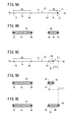
以下、破線形状パラメータと実際に描画される破線パターンとの関係について、直線状のパスの始点から終点までの間を11単位長でストロークする場合を例に挙げて、図11Aを参照しながら詳細に説明する。 Hereinafter, the relationship between the broken line shape parameter and the actually drawn broken line pattern will be described in detail with reference to FIG. 11A, taking as an example a case where a stroke is made from the start point to the end point of the linear path with a unit length of 11 units. Explained.
例えば、[4 2]{0}は、破線配列[4 2]と、破線フェーズ{0}とのパラメータの結合を意味する。そのうち、破線配列[4 2]は、連続して4単位長をONにし、その後、連続して2単位長をOFFにすることに対応する。つまり、破線パターンの周期単位は6単位長である。換言すれば、この破線パターンは、線素が4単位長、隙間が2単位長の繰り返しで構成される。 For example, [4 2] {0} means a combination of parameters of the broken line array [4 2] and the broken line phase {0}. Among them, the broken line array [42] corresponds to continuously turning on the 4 unit length and then turning off the 2 unit length continuously. That is, the period unit of the broken line pattern is 6 unit length. In other words, this broken line pattern is composed of a repetition of 4 unit length for the line element and 2 unit length for the gap.
一方、破線フェーズ{0}は、前記破線の周期パターンの位相ずれ量が0単位長であることに対応する。図11Aに示すように、{0}の破線パターンを上段のように予め定めた場合、{1}の破線パターンは中段にように決定される。これは、{1}の破線パターンは、{0}の破線パターンに対して各単位長を左側(パスの始点側)に1個ずつシフトした結果に対応する。同様に、{2}の破線パターンは、{0}の破線パターンに対して各単位長を左側(パスの始点側)に2個ずつシフトした結果に対応する。 On the other hand, the broken line phase {0} corresponds to the phase shift amount of the broken line periodic pattern being 0 unit length. As shown in FIG. 11A, when the {0} broken line pattern is determined in advance as in the upper stage, the {1} broken line pattern is determined in the middle stage. This corresponds to the result of shifting the unit length of the {1} broken line pattern one by one to the left (path start point side) with respect to the {0} broken line pattern. Similarly, the {2} dashed line pattern corresponds to the result of shifting each unit length by two to the left (path start point side) with respect to the {0} dashed line pattern.
このように、PDF仕様では、始点から終点までの間、所定の周期の繰り返しパターンに基づいて破線の描画形状を順次決定するという特徴を有する。 As described above, the PDF specification has a feature that the drawing shape of the broken line is sequentially determined from the start point to the end point based on the repetitive pattern of a predetermined period.
ところが、PDFの上記仕様を用いて、線状のパスに沿って破線パターンを生成した後、ラスタライズ処理する場合に予期しない問題が生じ得る。 However, an unexpected problem may occur when a rasterization process is performed after a broken line pattern is generated along a linear path using the above-mentioned specification of PDF.
例えば、各線素の始点及び終点(各隙間の終点及び始点)を決定する際、その始点又は終点の位置がRIP毎に異なり、位置ずれ誤差を生じる場合がある。この誤差は、RIPの演算アルゴリズムやソフトウエアバージョンの差異によって発生する、いわゆる演算誤差である。そのため、図11B及び図11Cに示すように、同じパス長であっても、生成される線素の数が異なる場合がある。 For example, when determining the start point and end point of each line element (end point and start point of each gap), the position of the start point or end point differs for each RIP, and a misalignment error may occur. This error is a so-called calculation error caused by a difference in RIP calculation algorithm and software version. Therefore, as shown in FIGS. 11B and 11C, the number of generated line elements may be different even with the same path length.
図11Bの例によると、上記演算誤差の影響により、線素200aの終点202aの位置と、線素200bの終点202bの位置が異なっているとする。すると、次の線素204aの始点206aはパスの終点位置208を超えた位置(右方側)に存在し、次の線素204bの始点206bはパスの終点位置208を超えない位置(左方側)に存在する。
In the example of FIG. 11B, it is assumed that the position of the
図11Cは、図11Bに示す上段の破線(線素200a、次の線素204a)及び下段の破線(線素200b、次の線素204b)にそれぞれ所定の線幅を付してストロークした結果を表す概略説明図である。
FIG. 11C shows a result of strokes with predetermined line widths added to the upper broken line (
予め指定された線幅とキャップ形式(端部処理形式)に従って、線素200aを中心軸とした塗り潰し領域210aが形成される。線素200bについても、線素200aと同様に、塗り潰し領域210bが形成されている。
In accordance with the line width and cap format (end processing format) specified in advance, a filled
ところが、パスの範囲外にある始点206a(上段の破線)には、次の線素204aを中心軸とした塗り潰し領域は形成されない。一方、パスの範囲内にある始点206b(下段の破線)には、次の線素204bの一部を中心軸とした長円形状の塗り潰し領域212が形成される。
However, a filled region with the
このように、線状のパスに沿って破線パターンを生成する際、RIPの演算アルゴリズムやソフトウエアバージョンに起因する演算誤差と、破線パターンの形状パラメータ等との組み合わせに応じて、パスの終点近傍における線素が不定に発生するので、目論見と異なる破線形状に変換される場合がある。そのため、破線を含む画像データに対してラスタライズ処理する場合、発生原因の特定が困難である予期しない印刷不具合の一因となり得る。特に、線幅が大きい場合にこの問題が顕在化する。 Thus, when generating a broken line pattern along a linear path, the vicinity of the end point of the path depends on the combination of the calculation error caused by the RIP calculation algorithm or software version, the shape parameter of the broken line pattern, etc. Since the line element in is generated indefinitely, it may be converted into a broken line shape different from the intended view. For this reason, when rasterizing the image data including the broken line, it may be a cause of an unexpected printing defect in which it is difficult to identify the cause of occurrence. In particular, this problem becomes apparent when the line width is large.
本発明は上記した問題を解決するためになされたもので、破線を含む画像データに対してラスタライズ処理を行う際に生じ得る印刷不具合を防止できるページ記述データ処理装置、方法及びプログラムを提供することを目的とする。 The present invention has been made to solve the above-described problem, and provides a page description data processing apparatus, method, and program capable of preventing a printing defect that may occur when rasterizing image data including a broken line. With the goal.
本発明に係るページ記述データ処理装置は、ページ記述データ中にパスをストロークするオブジェクトがあるか否かを確認するオブジェクト確認部と、パスをストロークするオブジェクトが含まれていた場合に、該オブジェクト中に破線パターンを決定する破線パターン決定オペレータが含まれているか否かを確認するオペレータ有無確認部と、破線パターン決定オペレータが含まれていた場合に、前記パスを構築するパス構築オペレータと前記破線パターン決定オペレータとに基づいて、前記パスに沿って形成される線素の始点の位置を推定する線素始点位置推定部と、前記線素の始点と前記パスの終点との距離が所定の閾値以下である場合に、該距離を長くするために、該パスの終点の位置を該パスに沿った別の位置に変更するパス終点位置変更部とを有することを特徴とする。 The page description data processing apparatus according to the present invention includes an object confirmation unit for confirming whether or not there is an object that strokes a path in the page description data, and an object that strokes a path. An operator presence / absence confirmation unit for confirming whether or not a broken line pattern determination operator for determining a broken line pattern is included, and a path construction operator for constructing the path and the broken line pattern when a broken line pattern determination operator is included. A line element start point position estimating unit that estimates a position of a start point of a line element formed along the path based on a determination operator, and a distance between the start point of the line element and the end point of the path is equal to or less than a predetermined threshold The path end point is changed to another position along the path to increase the distance. And having a location changing unit.
このように、線素の始点とパスの終点との距離が所定の閾値以下である場合に、該距離を長くするために、該パスの終点の位置を該パスに沿った別の位置に変更するパス終点位置変更部を設けたので、RIPによるラスタライズ処理の過程で、演算処理による誤差等の影響を受けることなく、パスの終点近傍において常に線素を発生させ、あるいは常に線素を発生させない。すなわち、線素が不定に発生する現象を未然に防止可能である。これにより、破線を含む画像データに対してラスタライズ処理を行う際に生じ得る印刷不具合を防止できる。 In this way, when the distance between the starting point of the line element and the end point of the path is equal to or less than a predetermined threshold, the position of the end point of the path is changed to another position along the path in order to increase the distance. Since the path end point position changing unit is provided, a line element is always generated in the vicinity of the end point of the path, or is not always generated in the process of rasterizing processing by RIP, without being affected by errors due to arithmetic processing. . That is, it is possible to prevent a phenomenon in which line elements are generated indefinitely. Thereby, it is possible to prevent a printing defect that may occur when performing rasterization processing on image data including a broken line.
また、前記線素始点位置推定部は、曲線状のパスに沿って形成される線素の始点の位置を推定することが好ましい。特に、曲線形状を特定するための演算は複雑であり、パスの終点近傍において線素が不定に発生する可能性が高くなるので、より一層効果的である。 Moreover, it is preferable that the said line element starting point position estimation part estimates the position of the starting point of the line element formed along a curvilinear path. In particular, the calculation for specifying the curve shape is complicated, and there is a high possibility that a line element is generated indefinitely in the vicinity of the end point of the path.
さらに、前記パス終点位置変更部は、前記パスを外挿して予測された位置を前記別の位置とすることが好ましい。 Further, it is preferable that the path end point position changing unit extrapolates the path and sets the predicted position as the other position.
さらに、前記パス終点位置変更部は、前記ページ記述データをラスタライズする際の解像度に応じて前記所定の閾値を決定することが好ましい。これにより、パスの終点近傍における線素の長さを適切に制御できる。 Furthermore, it is preferable that the path end point position changing unit determines the predetermined threshold according to a resolution when rasterizing the page description data. Thereby, the length of the line element in the vicinity of the end point of the path can be appropriately controlled.
本発明に係るページ記述データ処理方法は、ページ記述データ中にパスをストロークするオブジェクトがあるか否かを確認するステップと、パスをストロークするオブジェクトが含まれていた場合に、該オブジェクト中に破線パターンを決定する破線パターン決定オペレータが含まれているか否かを確認するステップと、破線パターン決定オペレータが含まれていた場合に、前記パスを構築するパス構築オペレータと前記破線パターン決定オペレータとに基づいて、前記パスに沿って形成される線素の始点の位置を推定するステップと、前記線素の始点と前記パスの終点との距離が所定の閾値以下である場合に、該距離を長くするために、該パスの終点の位置を該パスに沿った別の位置に変更するステップとを備えることを特徴とする。 The page description data processing method according to the present invention includes a step of confirming whether or not there is an object that strokes a path in the page description data, and when an object that strokes a path is included, a broken line is included in the object. A step of confirming whether or not a broken line pattern determining operator for determining a pattern is included; and, if a broken line pattern determining operator is included, based on the path building operator for building the path and the broken line pattern determining operator And estimating the position of the start point of the line element formed along the path, and increasing the distance when the distance between the start point of the line element and the end point of the path is equal to or less than a predetermined threshold value. Therefore, a step of changing the position of the end point of the path to another position along the path is provided.
本発明に係るプログラムは、コンピュータを、ページ記述データ中にパスをストロークするオブジェクトがあるか否かを確認する手段、パスをストロークするオブジェクトが含まれていた場合に、該オブジェクト中に破線パターンを決定する破線パターン決定オペレータが含まれているか否かを確認する手段、破線パターン決定オペレータが含まれていた場合に、前記パスを構築するパス構築オペレータと前記破線パターン決定オペレータとに基づいて、前記パスに沿って形成される線素の始点の位置を推定する手段、前記線素の始点と前記パスの終点との距離が所定の閾値以下である場合に、該距離を長くするために、該パスの終点の位置を該パスに沿った別の位置に変更する手段として機能させることを特徴とする。 The program according to the present invention allows a computer to check whether there is an object that strokes a path in the page description data. When an object that strokes a path is included, a broken line pattern is included in the object. Means for confirming whether or not a broken line pattern determining operator to be determined is included, and when a broken line pattern determining operator is included, based on the path building operator for building the path and the broken line pattern determining operator, Means for estimating the position of the starting point of the line element formed along the path, and in order to increase the distance when the distance between the starting point of the line element and the end point of the path is equal to or less than a predetermined threshold, It is characterized by functioning as means for changing the position of the end point of the path to another position along the path.
本発明に係るページ記述データ処理装置、方法及びプログラムによれば、ページ記述データ中にパスをストロークするオブジェクトがあるか否かを確認し、該オブジェクト中に破線パターンを決定する破線パターン決定オペレータが含まれているか否かを確認し、前記パスを構築するパス構築オペレータと前記破線パターン決定オペレータとに基づいて、前記パスに沿って形成される線素の始点の位置を推定し、前記線素の始点と前記パスの終点との距離が所定の閾値以下である場合に、該距離を長くするために、該パスの終点の位置を該パスに沿った別の位置に変更するようにしたので、RIPによるラスタライズ処理の過程で、演算処理による誤差等の影響を受けることなく、パスの終点近傍において常に線素を発生させ、あるいは常に線素を発生させない。すなわち、線素が不定に発生する現象を未然に防止可能である。これにより、破線を含む画像データに対してラスタライズ処理を行う際に生じ得る印刷不具合を防止できる。 According to the page description data processing apparatus, method, and program of the present invention, a broken line pattern determination operator that checks whether there is an object that strokes a path in the page description data and determines a broken line pattern in the object. And confirming the position of the starting point of the line element formed along the path based on the path construction operator that constructs the path and the broken line pattern determination operator, and When the distance between the start point of the path and the end point of the path is equal to or less than a predetermined threshold, the position of the end point of the path is changed to another position along the path in order to increase the distance. In the course of rasterization processing by RIP, line elements are always generated in the vicinity of the end point of the path without being affected by errors due to arithmetic processing, or always It does not generate the original. That is, it is possible to prevent a phenomenon in which line elements are generated indefinitely. Thereby, it is possible to prevent a printing defect that may occur when performing rasterization processing on image data including a broken line.
以下、本発明に係るページ記述データ処理装置、方法及びプログラムの実施形態について、これを実施する出版システムを例として、添付の図面を参照しながら説明する。 Hereinafter, embodiments of a page description data processing apparatus, method, and program according to the present invention will be described with reference to the accompanying drawings, taking as an example a publishing system that implements the same.
図1は、本実施の形態に係るページ記述データ処理方法を実施する出版システム10の概略構成図を示している。
FIG. 1 is a schematic configuration diagram of a
出版システム10は、プリプレス工程と印刷工程並びに図示しない製本工程とから構成される。
The
プリプレス工程には、DTPコンピュータ12と、パーソナルコンピュータ等により構成されるページ記述データ処理装置14と、RIP16と、プリンタ20と、プレートセッタ22が備えられる。
The prepress process includes a page description
DTPコンピュータ12は、オペレータによって編集された文字や画像等の要素を基に、ページ毎のイメージを表現するページ記述言語で記述されたページ記述データDpを作成する。
The
ページ記述データ処理装置14は、DTPコンピュータ12から出力されたページ記述データDpの内容(属性)を調べ、調査結果に応じて、所定の属性を有するページ記述データDpに対して特定の処理を行い、処理後のロバスト化ページ記述データDp´を作成するか、所定の属性を有さないページ記述データDpをそのまま出力する。なお、ページ記述データ処理装置14による処理機能は、DTPコンピュータ12に一体的に組み込み、ページ記述データ処理装置14を省略することもできる。
The page description
RIP16は、ページ記述データ処理装置14から出力されたページ記述データDp又はロバスト化ページ記述データDp´を、例えばCMYK4版それぞれのラスタイメージデータDrに変換する。
The
プリンタ20は、ラスタイメージデータDrに基づきハードコピーであるプルーフ18を出力する。
The
プレートセッタ22は、プリンタ20によりプリントされたプルーフ18がオペレータによってOKであると判断された場合に、オペレータによる開始スイッチの操作後、RIP16の出力であるラスタイメージデータDrからCMYK4版のそれぞれの刷版PPを作成して出力する。
When the operator determines that the proof 18 printed by the
印刷工程には、印刷機24が備えられる。印刷機24には、CMYK4版の刷版PPが装着され、刷版PPに担持されたCMYKのインキが本紙上に転移されて多色(4色)刷りが行われることで印刷物26が完成する。
A
図2は、ページ記述データ処理装置14のCPUがROMに記録されたプログラムを実行することで達成される機能のブロック図を示している。
FIG. 2 shows a block diagram of functions achieved by the CPU of the page description
ページ記述データ処理装置14は、入力インタフェース(入力I/F)32を通じて入力したページ記述データDpを分析処理したロバスト化ページ記述データDp´を作成し又は手を加えない元のままのページ記述データDpを作成し、出力インタフェース(出力I/F)34を通じて出力する。
The page description
ページ記述データ処理装置14は、上記の入出力インタフェース32、34の他、分析処理に係わるオブジェクト確認部36(構造解析部37と、パスオブジェクト有無確認部38と、パスペイントオペレータ属性確認部40とを含む。)と、破線パターン決定オペレータ有無確認部42と、線素始点位置推定部44と、パス終点位置変更部46とを備える。
In addition to the input /
なお、本明細書における「パスオブジェクト」は、直線、矩形、曲線(例えば3次ベジェ曲線)で構成される任意の形状である。 The “path object” in this specification is an arbitrary shape composed of a straight line, a rectangle, and a curve (for example, a cubic Bezier curve).
また、本明細書における「パスペイントオペレータ」は、パスオブジェクトを終了させるオペレータであり、カレントパスに線幅を付して線を描くオペレータ(以下、便宜のため「ストローク系オペレータ」という。)、又はカレントパスが生成する閉空間を塗りつぶすオペレータ(以下、便宜のため「塗りつぶし系オペレータ」という。)のうちいずれかの属性を有する。 Also, the “path paint operator” in this specification is an operator that ends a path object, an operator that draws a line by adding a line width to the current path (hereinafter referred to as a “stroke operator” for convenience), Alternatively, it has one of the attributes of an operator that fills the closed space generated by the current path (hereinafter referred to as “painting operator” for convenience).
さらに、本明細書における「破線パターン決定オペレータ」は、パスをストロークするときの破線パターンの記述方法を設定するオペレータである。PDFでは、「d」の1種類のオペレータが定義されている。「d」オペレータにより設定可能な変数として、交互に現れる個々の線素と隙間との長さを指定する「破線配列」と、破線の開始位置となる先頭の位置を指定する「破線フェーズ」とが定義されている。以下、「破線パターン決定オペレータ」が含まれない(存在しない)ことには、該オペレータ自体が存在しない場合のみならず、該オペレータには実線を表す変数が設定されており、実質的に破線パターンではないことが含まれる。 Furthermore, the “broken line pattern determination operator” in this specification is an operator that sets a description method of a broken line pattern when a path is stroked. In the PDF, one type of operator “d” is defined. As a variable that can be set by the “d” operator, a “dashed line array” that specifies the lengths of individual line elements and gaps that appear alternately, and a “dashed line phase” that specifies the start position of the starting point of the broken line Is defined. Hereinafter, not including (not existing) “broken line pattern determination operator” includes not only the case where the operator itself does not exist, but also a variable representing a solid line is set in the operator. It is not included.
さらに、本明細書における「パス構築オペレータ」は、パスの物理的形状を定義するオペレータをいう。PDFでは、「m」「l」「c」「v」「y」「h」「re」の7種類のオペレータが定義されている。 Furthermore, the “path construction operator” in this specification refers to an operator that defines the physical shape of a path. In PDF, seven types of operators “m”, “l”, “c”, “v”, “y”, “h”, and “re” are defined.
さらに、本明細書における「曲線パス構築オペレータ」は、パス構築オペレータのうち、カレントパスに曲線を追加するオペレータをいう。PDFでは、「c」「v」「y」の3種類のオペレータが定義され、いずれのオペレータも3次ベジェ曲線を追加するものである。 Further, the “curve path construction operator” in this specification refers to an operator that adds a curve to the current path among the path construction operators. In PDF, three types of operators “c”, “v”, and “y” are defined, and all operators add a cubic Bezier curve.
さらに、本明細書における「直線パス構築オペレータ」は、パス構築オペレータのうち、カレントパスに直線を追加するオペレータをいう。PDFでは、「l」の1種類のオペレータが定義されている。 Further, the “straight path construction operator” in this specification refers to an operator that adds a straight line to the current path among the path construction operators. In PDF, one type of operator “l” is defined.
図3は、「l」オペレータが生成する直線を示すグラフである。この直線状のパス48は、始点PA(x1,y1)及び終点PB(x2,y2)により定義されている。
FIG. 3 is a graph showing a straight line generated by the “l” operator. The
変数tの値を0〜1まで変化させることにより、始点PAと終点PBとを結ぶパス48が生成される。ここで、変数tにおけるパス48上の点の座標P(x(t),y(t))は、次の(1)式及び(2)式で算出される。
x(t)=(1−t)x1+tx2 ……(1)
y(t)=(1−t)y1+ty2 ……(2)
By varying the value of the variable t to 0-1, the
x (t) = (1-t) x 1 + tx 2 (1)
y (t) = (1-t) y 1 + ty 2 (2)
ここで、(1)式及び(2)式より、x(0)=x1、y(0)=y1、x(1)=x2、y(1)=y2であることから諒解されるように、変数tが0〜1に変化すると、パス48上の点Pは、矢印E1の方向に始点PAから終点PBまで連続的に移動する。
Here, from Equations (1) and (2), x (0) = x 1 , y (0) = y 1 , x (1) = x 2 , y (1) = y 2 is as, the variable t is changed to 0-1, the point P on the
図4は、「c」オペレータが生成する3次ベジェ曲線を示すグラフである。この曲線状のパス50は、2つの端点P0(x0,y0)及びP3(x3,y3)並びに2つの制御点P1(x1,y1)及びP2(x2,y2)により定義されている。
FIG. 4 is a graph showing a cubic Bezier curve generated by the “c” operator. The
変数tの値を0〜1まで変化させることにより、始点P0と終点P3とを結ぶパス50が生成される。ここで、変数tにおけるパス50上の点の座標P(x(t),y(t))は、次の(3)式及び(4)式で算出される。
x(t)=(1−t)3x0+3t(1−t)2x1+3t2(1−t)x2+t3x3 ……(3)
y(t)=(1−t)3y0+3t(1−t)2y1+3t2(1−t)y2+t3y3 ……(4)
By changing the value of the variable t from 0 to 1 , a
x (t) = (1- t) 3 x 0 + 3t (1-t) 2 x 1 + 3t 2 (1-t) x 2 + t 3 x 3 ...... (3)
y (t) = (1- t) 3
ここで、(3)式及び(4)式より、x(0)=x0、y(0)=y0、x(1)=x3、y(1)=y3であることから諒解されるように、変数tが0〜1に変化すると、パス50上の点Pは、矢印E2の方向に始点P0から終点P3まで連続的に移動する。なお、破線で示す線分P0P1は点P0におけるパス50の接線である。また、破線で示す線分P2P3は点P3におけるパス50の接線である。
Here, from equations (3) and (4), x (0) = x 0 , y (0) = y 0 , x (1) = x 3 , y (1) = y 3 As described above, when the variable t changes from 0 to 1, the point P on the
基本的には、以上のように構成される出版システム10のページ記述データ処理装置14の動作について、図5のフローチャート及び図2の機能ブロック図を参照して説明する。
Basically, the operation of the page description
ステップS1において、ページ記述データ処理装置14は、DTPコンピュータ12から出力されるページ記述データDpをページ毎に取り込む。
In step S1, the page description
ステップS2において、構造解析部37は、ページ記述データDpの構造を解析してページに含まれるオブジェクトを抽出する。その後、パスオブジェクト有無確認部38は、抽出されたオブジェクトにパスオブジェクトが含まれているか否かを確認する。パスオブジェクトが含まれていない場合には、ページ記述データDpを、変更せずそのまま出力インタフェース34を通じて出力する(ステップS8)。
In step S2, the structure analysis unit 37 analyzes the structure of the page description data Dp and extracts objects included in the page. Thereafter, the path object presence / absence confirmation unit 38 confirms whether or not a path object is included in the extracted object. If the path object is not included, the page description data Dp is output through the
ステップS3において、パスペイントオペレータ属性確認部40は、ステップS2により確認された前記パスオブジェクトにストローク系オペレータ、例えば、オペレータ「S」「s」等が含まれているか否かを確認する。ストローク系オペレータが含まれていない(すなわち、塗りつぶし系オペレータ「f」「F」等が含まれている)場合には、ページ記述データDpを、変更せずそのまま出力インタフェース34を通じて出力する(ステップS8)。
In step S <b> 3, the path paint operator attribute confirmation unit 40 confirms whether or not the path object confirmed in step S <b> 2 includes a stroke operator, for example, operators “S” and “s”. If the stroke operator is not included (that is, the paint operators “f”, “F”, etc. are included), the page description data Dp is output as it is through the
ステップS4において、破線パターン決定オペレータ有無確認部42は、ステップS2により確認された前記パスオブジェクトに破線パターン決定オペレータ、すなわちオペレータ「d」が含まれているか否かを確認する。破線パターン決定オペレータが含まれていない場合には、ページ記述データDpを、変更せずそのまま出力インタフェース34を通じて出力する(ステップS8)。
In step S4, the broken line pattern determination operator presence /
ステップS5において、線素始点位置推定部44は、ステップS2により確認された前記パスオブジェクトと、ステップS4により確認された前記破線パターン決定オペレータとに基づいて、パスに沿って形成される線素の始点の位置を推定する。ここで、この推定方法について、図6のフローチャートを参照しながら詳細に説明する。
In step S5, the line element starting point
ステップS51において、線素始点位置推定部44は、パス構築オペレータからパスを決定するパラメータを取得する。図3の例では、オペレータ属性(「l」)、始点PA(x1,y1)及び終点PB(x2,y2)である。図4の例では、オペレータ属性(「c」、「v」、又は「y」)、始点P0(x0,y0)、終点P3(x3,y3)、制御点P1(x1,y1)及び制御点P2(x2,y2)である。
In step S51, the line element starting point
また、ユーザ空間(装置独立座標系)とデバイス空間(装置依存座標系)との対応付けを行うために、縦横のラスタライズ解像度も併せて取得する。この解像度の単位として、dpi(dot per inch)やppi(pixel per inch)等が用いられる。 Also, in order to associate the user space (device independent coordinate system) with the device space (device dependent coordinate system), the vertical and horizontal rasterization resolutions are also acquired. As a unit of resolution, dpi (dot per inch), ppi (pixel per inch), or the like is used.
ステップS52において、線素始点位置推定部44は、破線パターンを決定するパラメータを取得する。ここでは、「d」オペレータに設定される「破線配列」及び「破線フェーズ」(破線形状パラメータ)に相当する。
In step S52, the line element starting point
ステップS53において、線素始点位置推定部44は、複数の線素としての始点・終点の位置を推定する。以下、ユーザ空間上で線素の始点の位置を推定する方法について詳細に説明する。
In step S53, the line element start point
パス48、50上の点Pの座標を(x(t),y(t))とするとき、区間[u,v]でのパス48、50の線分の長さI(u,v)は、次の(5)式で算出される。

なお、0≦u≦1、0≦v≦1である。この(5)式に基づいて、線素の始点・終点位置を推定することができる。 Note that 0 ≦ u ≦ 1 and 0 ≦ v ≦ 1. Based on this equation (5), the start point and end point position of the line element can be estimated.
以下、図3に示す直線状のパス48の例に基づいて、線素始点位置推定部44が線素の始点・終点の位置を推定する手順について説明する。
Hereinafter, a procedure in which the line element start point
図7Aに示すように、破線形状パラメータが[D L−D]{S}で設定されたものとする。ここで、D、L及びSはいずれも正数であって、整数値のみならず、実数値を採ることができる。 As shown in FIG. 7A, it is assumed that the broken line shape parameter is set by [D L -D] {S}. Here, D, L, and S are all positive numbers and can take not only integer values but also real values.
すると、図7Bに示すように、パス48の始点PA(x1,y1)と、終点PB(x2,y2)と、上記破線形状パラメータに基づいて、5つの線素A1〜A5の形状、具体的には、始点{Q1、Q3、Q5、Q7、Q9}及び終点{Q2、Q4、Q6、Q8、Q10}の位置をそれぞれ推定できる。以下、その推定方法について詳細に説明する。
Then, as shown in FIG. 7B, based on the start point P A (x 1 , y 1 ) and the end point P B (x 2 , y 2 ) of the
先ず、描画開始位置としての線素A1(長さL1)の始点Q1の位置は、パス48の始点PAの位置(t1=0)と推定される。そして、I(t1,t2)=D−Sを満たすt2を算出し、(1)式及び(2)式に基づいてt=t2に相当する位置を算出する。線素A1の終点Q2の位置は、位置(x(t2),y(t2))であると推定される。 First, the position of the start point to Q 1 line element A 1 (length L 1) as a drawing start position is estimated and the position of the start point P A of the path 48 (t 1 = 0). Then, to calculate the t 2 satisfying I (t 1, t 2) = D-S, and calculates a position corresponding to t = t 2, based on (1) and (2) below. The position of the end point Q 2 of the line element A 1 is estimated to be the position (x (t 2 ), y (t 2 )).
次いで、I(t2,t3)=L−Dを満たすt3を算出し、(1)式及び(2)式に基づいてt=t3に相当する位置を算出する。線素A2(長さL2)の始点Q3の位置は、算出された位置(x(t3),y(t3))であると推定される。そして、I(t3,t4)=Dを満たすt4を算出し、(1)式及び(2)式に基づいてt=t4に相当する位置を算出する。線素A2の終点Q4の位置は、位置(x(t4),y(t4))であると推定される。 Then, to calculate the t 3 when satisfy I (t 2, t 3) = L-D, and calculates the position corresponding to t = t 3 based on (1) and (2) below. The position of the starting point Q 3 of the line element A 2 (length L 2 ) is estimated to be the calculated position (x (t 3 ), y (t 3 )). Then, to calculate the t 4 when satisfy I (t 3, t 4) = D, calculates a position corresponding to t = t 4 based on (1) and (2) below. The position of the end point Q 4 of the line element A 2 is estimated to be the position (x (t 4 ), y (t 4 )).
以下同様にして、始点{Q1、Q3、Q5、Q7、Q9}及び終点{Q2、Q4、Q6、Q8、Q10}の座標がそれぞれ推定される。なお、本実施の形態では、線素の始点・終点の位置の両方を推定しているが、終点の位置を求めることなく始点の位置のみを推定してもよいことはいうまでもない。 Similarly, the coordinates of the start point {Q 1 , Q 3 , Q 5 , Q 7 , Q 9 } and the end point {Q 2 , Q 4 , Q 6 , Q 8 , Q 10 } are estimated respectively. In the present embodiment, both the start point and end point positions of the line element are estimated, but it is needless to say that only the start point position may be estimated without obtaining the end point position.
次いで、図4に示す曲線状のパス50の例に基づいて、線素始点位置推定部44が線素の始点・終点の位置を推定する手順について説明する。特に、曲線形状を特定するための演算は複雑であり、パス50の終点近傍において線素が不定に発生する可能性が高くなるので、より一層効果的である。なお、破線形状パラメータは、図7Aと同様に設定されたものとする。
Next, a procedure in which the line element start point
パス50の始点P0(x0,y0)と、終点P3(x3,y3)と、上記破線形状パラメータに基づいて、5つの線素A1〜A5の形状、具体的には、始点{Q1、Q3、Q5、Q7、Q9}及び終点{Q2、Q4、Q6、Q8、Q10}の座標をそれぞれ推定できる。以下、その推定方法について詳細に説明する。
Based on the start point P 0 (x 0 , y 0 ) and the end point P 3 (x 3 , y 3 ) of the
先ず、描画開始位置としての線素A1(長さL1)の始点Q1の位置は、パス50の始点P 0 の位置(t1=0)と推定される。そして、I(t1,t2)=D−Sを満たすt2を算出し、(3)式及び(4)式に基づいてt=t2に相当する位置を算出する。線素A1の終点Q2の位置は、位置(x(t2),y(t2))であると推定される。
First, the position of the starting point Q 1 of the line element A 1 (length L 1 ) as the drawing start position is estimated as the position (t 1 = 0) of the starting point P 0 of the
次いで、I(t2,t3)=L−Dを満たすt3を算出し、(3)式及び(4)式に基づいてt=t3に相当する位置を算出する。線素A2(長さL2)の始点Q3の位置は、算出された位置(x(t3),y(t3))であると推定される。そして、I(t3,t4)=Dを満たすt4を算出し、(3)式及び(4)式に基づいてt=t4に相当する位置を算出する。線素A2の終点Q4の位置は、位置(x(t4),y(t4))であると推定される。 Then, to calculate the t 3 when satisfy I (t 2, t 3) = L-D, and calculates the position corresponding to t = t 3 based on the expressions (3) and (4). The position of the starting point Q 3 of the line element A 2 (length L 2 ) is estimated to be the calculated position (x (t 3 ), y (t 3 )). Then, to calculate the t 4 when satisfy I (t 3, t 4) = D, calculates a position corresponding to t = t 4, based on the expressions (3) and (4). The position of the end point Q 4 of the line element A 2 is estimated to be the position (x (t 4 ), y (t 4 )).
以下同様にして、始点{Q1、Q3、Q5、Q7、Q9}及び終点{Q2、Q4、Q6、Q8、Q10}の座標がそれぞれ推定される。 Similarly, the coordinates of the start point {Q 1 , Q 3 , Q 5 , Q 7 , Q 9 } and the end point {Q 2 , Q 4 , Q 6 , Q 8 , Q 10 } are estimated respectively.
なお、1つの曲線パス構築オペレータを折れ線状のパスに対応する複数の直線パス構築オペレータに置き換えた後に、上記推定を行ってもよい。これにより、演算を容易にして処理時間を短縮できる。 Note that the above estimation may be performed after replacing one curved path construction operator with a plurality of straight path construction operators corresponding to a polygonal path. As a result, the calculation can be facilitated and the processing time can be shortened.
以上のようにして、パスに沿って形成される複数の線素としての始点・終点の位置を推定することができる(ステップS5)。 As described above, it is possible to estimate the positions of the start and end points as a plurality of line elements formed along the path (step S5).
図5に戻って、ステップS6において、線素の始点とパスの終点との距離が所定の閾値以下であるか否かを判定する。この距離が所定の閾値を超える場合には、ページ記述データDpを、変更せずそのまま出力インタフェース34を通じて出力する(ステップS8)。
Returning to FIG. 5, in step S6, it is determined whether or not the distance between the start point of the line element and the end point of the path is equal to or less than a predetermined threshold value. If this distance exceeds a predetermined threshold value, the page description data Dp is output through the
ステップS7において、パス終点位置変更部46は、線素の始点とパスの終点との距離を長くするために、該パスの終点の位置を該パスに沿った別の位置に変更する。その具体例と作用効果について、図9A〜図9Eを参照しながら説明する。
In step S7, the path end point
図9Aに示すように、終点70まで延在するパス72を破線パターンでストロークする場合、「ON」と表示された範囲内で線素74、76が形成されるものとする。それ以外の範囲では、互いに隣接する線素の隙間としての非線素77が形成される。一例として、線素74の始点78及び終点80と、線素76の始点82及び終点70(パス72の終点と一致する。)の周辺にラウンドキャップを付加する処理を行う場合を考える。ここで、「ラウンドキャップ」とは、線幅に等しい直径の半円弧を端点の周囲に描き、内部を塗り潰すキャップ方式である(非特許文献1の123ページを参照のこと)。
As shown in FIG. 9A, when the
上述したステップS6(図5参照)では、複数の線素74、76の始点78、82が判定領域84内の点であるか否かにより判定される。なお、破線を構成するすべての線素74、76について前記判定を行ってもよい。また、複数の線素74、76のうち、始点の位置がパス72の終点70に最も近い線素、この場合は線素76を抽出して、その始点82のみに対して前記判定を行ってもよい。
In step S <b> 6 (see FIG. 5) described above, the determination is made based on whether or not the start points 78 and 82 of the plurality of
判定領域84は、パス72の終点70を中心とする半径δrの円領域である。図9Aに示す場合には、線素74、76の始点78、82はいずれも判定領域84外の点であるので、パス72を変更することなくストローク処理及びキャップ処理がなされる。
The
その結果、図9Bに示すように、パス72に沿ってストロークされ、線素74、76に所定の線幅を付されることで、塗り潰し領域86、88が形成される。なお、始点78、82、終点80、70の一端に半円型のキャップがそれぞれ付されている。
As a result, as shown in FIG. 9B, strokes are made along the
一方、図9Cに示すように、線素76の始点82が判定領域84内の点である場合について説明する。例えば、図9A及び図9Bで説明した場合と同様にストローク処理等を行うと、図9Dのような描画結果が得られる。
On the other hand, as shown in FIG. 9C, a case where the
始点82と終点70とは極めて近接しているので、線素76は短くなるとともに、塗り潰し領域92の面積は小さくなる。このような場合、演算処理の誤差等の影響により、始点82と終点70との位置関係が変化し、始点82の位置がパス72の範囲外に存することが生じ得る。そうすると、線素76(塗り潰し領域92)が不定に発生する可能性がある。
Since the
そこで、この問題を解消するため、線素76の始点82とパス72の終点70との距離を長くするために、もとの終点70の位置を新たな終点90の位置に変更する。具体的には、終点の位置をパス72の延在方向(始点から終点に向かう方向)に対して所定の長さだけ移動することで、パス72を延長する。例えば、前記所定の長さは、判定領域84を画定する円の直径(=2・δr)とすることができる。
In order to solve this problem, the
ここで、δrの値は、RIP16による演算処理の誤差等を考慮して決定されている。例えば、2400〜4800dpi程度の高い解像度を有する画像データに対して、δrの値を7200dpi相当の値に設定しておくことが好ましい。また、ラスタライズ解像度Δの値に応じてδrの値を決定してもよい。パス72の終点70近傍における線素76の長さを適切に制御できるからである。
Here, the value of δr is determined in consideration of an error in arithmetic processing by the
その結果、図9Eに示すように、新たな線素94の長さは、線素76(図9D参照)と比較して2・δrだけ長く設けられている。そうすると、RIP16による演算処理の誤差等の影響により、新たな線素94の長さが変動した(特に、短くなった)としても、破線パターンの要素としての新たな線素94は必ず存在するので、塗り潰し領域96が常に形成される。これにより、線素76(塗り潰し領域92)が不定に発生することを未然に防止できる。
As a result, as shown in FIG. 9E, the length of the
なお、図9Cに例示する方法では、パス72を終点70側に外挿して予測された位置を新たな終点90として決定する。この外挿方法は、公知のアルゴリズムを適用することができる。
In the method illustrated in FIG. 9C, the predicted position is determined as a
例えば、新たな終点90の座標として、(1)〜(4)式に対して、t=1+δt(δtは、微小の正値)を代入して得られた(x,y)を用いてもよい。これにより、パス48、50の形状に沿った適切な線素が形成される。
For example, as the coordinates of the
なお、線素の終点の位置を変更する具体例としては、図9A〜図9Eに限ることなく、図10A〜図10Cの構成であってもよい。 Note that specific examples of changing the position of the end point of the line element are not limited to FIGS. 9A to 9E, and the configurations of FIGS. 10A to 10C may be used.
例えば、図10Aに示すように、新たな終点98をパス72上の位置に設定することで、パス72を短縮してもよい。この場合は、短縮された新たなパスの範囲内に始点82が存しないので、図9Eに示す塗り潰し領域96は常に形成されない(図10B参照)。これにより、線素(塗り潰し領域)が不定に発生することを未然に防止できる。
For example, as shown in FIG. 10A, the
あるいは、図10Cに示すように、円形状の判定領域84(図9A及び図9C参照)ではなく、矩形状の判定領域100であってもよい。また、x軸方向、y軸方向に対応する閾値δx、δyは、同一の又は異なる値にしてもよい。さらに、判定領域84、100のように、終点70に対して点対称ではなく、非対称な領域として設けてもよい。
Alternatively, as shown in FIG. 10C, a
以上のようにして、パス終点位置変更部46は、パスの終点を変更する(ステップS7)。具体的には、パス構築オペレータの終点70を、上述した方法で決定された別の終点90の座標に置換する(図9C参照)。
As described above, the path end point
図5に戻って、ステップS8において、パス終点位置変更部46によりパスの終点が変更されたページ記述データDp’を、出力インタフェース34を通じて出力する。
Returning to FIG. 5, in step S <b> 8, the page description data Dp ′ whose path end point has been changed by the path end point
このようにして、図1に示すように、ページ記述データ処理装置14に入力されたページ記述データDpは、そのまま(Dp)又はパス構築オペレータ置換処理が施された後(Dp’)、RIP16側に供給される。その結果、塗り潰し領域96有りの状態(図9E参照)又は塗り潰し領域無しの状態(図10B参照)のいずれか一方になるように、安定して出力することができる。
In this way, as shown in FIG. 1, the page description data Dp input to the page description
以上のように、ページ記述データDp中にパス48、50をストロークするオブジェクトがあるか否かを確認し、前記オブジェクト中に破線パターンを決定する破線パターン決定オペレータが含まれているか否かを確認し、パス48、50を構築するパス構築オペレータと前記破線パターン決定オペレータとに基づいて、パス48、50に沿って形成される線素A1〜A5の始点{Q1、Q3、Q5、Q7、Q9}の位置を推定し、始点{Q1、Q3、Q5、Q7、Q9}とパス48、50の終点PB(P3)との距離が所定の閾値以下である場合に、該距離を長くするために、パス48、50の終点PB(P3)の位置をパス48、50に沿った別の位置に変更するようにしたので、RIP16によるラスタライズ処理の過程で、演算処理による誤差等の影響を受けることなく、パス48、50の終点近傍において常に線素を発生させ、あるいは常に線素を発生させない。すなわち、線素(特にA5)が不定に発生する現象を未然に防止可能である。これにより、破線を含む画像データに対してラスタライズ処理を行う際に生じ得る印刷不具合を防止できる。
As described above, it is confirmed whether or not there is an object that strokes the
なお、この発明は、上述した実施形態に限定されるものではなく、この発明の主旨を逸脱しない範囲で自由に変更できることは勿論である。 In addition, this invention is not limited to embodiment mentioned above, Of course, it can change freely in the range which does not deviate from the main point of this invention.
本実施の形態ではPDFを中心に説明したが、ページ記述言語はこれに限定されることはない。例えば、AdobeSystems社のPostScript(登録商標)やXPS(XML Paper Specification)等に対しても本発明を適用できる。 In the present embodiment, the description has been made centering on PDF, but the page description language is not limited to this. For example, the present invention can be applied to PostScript (registered trademark) of Adobe Systems, XPS (XML Paper Specification), and the like.
また、本実施の形態では、パス48、50の終点の位置を変更するようにしたが、パス48、50の始点PA(P0)の位置をパス48、50に沿った別の位置に変更しても、同様の作用効果を得ることができる。
In the present embodiment, the positions of the end points of the
10…出版システム 12…DTPコンピュータ
14…ページ記述データ処理装置 16…RIP
18…プルーフ 20…プリンタ
22…プレートセッタ 24…印刷機
26…印刷物 36…オブジェクト確認部
37…構造解析部 38…パスオブジェクト有無確認部
40…パスペイントオペレータ属性確認部
42…破線パターン決定オペレータ有無確認部
44…線素始点位置推定部 46…パス終点位置変更部
48、50、72…パス
70、80、202a、202b、PB、P3、Q2、Q4、Q6、Q8、Q10…終点
74、76、94、200a、200b、204a、204b、A、A1〜A5…線素
78、82、206a、206b、PA、P0、Q1、Q3、Q5、Q7、Q9…始点
84、100…判定領域
86、88、92、96、210a、210b、212…塗り潰し領域
90、98…新たな終点 96…新たな線素
208…終点位置
10 ...
DESCRIPTION OF
Claims (7)
パスをストロークするオブジェクトが含まれていた場合に、該オブジェクト中に、線素と隙間が交互に現われて周期性を有する破線パターンを決定する破線パターン決定オペレータが含まれているか否かを確認するオペレータ有無確認部と、
破線パターン決定オペレータが含まれていた場合に、前記パスを構築するパス構築オペレータと前記破線パターン決定オペレータとに基づいて、前記パスに沿って形成される前記線素の始点の位置を推定する線素始点位置推定部と、
前記線素の始点と前記パスの終点との距離が所定の閾値以下である場合に、該距離を長くするために、前記パスの始点における前記周期性の位相を固定しつつ、前記パスの終点の位置を前記パスに沿った別の位置に変更するパス終点位置変更部と
を有することを特徴とするページ記述データ処理装置。 An object confirmation unit for confirming whether there is an object that strokes a path in the page description data;
When an object that strokes a path is included, it is checked whether or not a broken line pattern determination operator for determining a broken line pattern having periodicity in which line elements and gaps appear alternately is included in the object. An operator presence confirmation unit;
Line if that contained dashed pattern determining operator, the a path construction operator to build the paths based on the broken line pattern determining operator to estimate the position of the start point of the line element formed along said path A starting point position estimation unit;
When the distance between the start point of the line element and the end point of the path is equal to or smaller than a predetermined threshold, the end point of the path is fixed while fixing the phase of the periodicity at the start point of the path in order to increase the distance. page description data processing apparatus the position and having a path end position changing unit to change to a different position along the path.
前記線素始点位置推定部は、曲線状のパスに沿って形成される前記線素の始点の位置を推定する
ことを特徴とするページ記述データ処理装置。 The page description data processing device according to claim 1, wherein
The line containing the start position estimating unit, the page description data processing apparatus characterized by estimating the position of the start point of the line element is formed along a curved path.
前記パス終点位置変更部は、前記パスを外挿して予測された位置を前記別の位置とする
ことを特徴とするページ記述データ処理装置。 In the page description data processing device according to claim 1 or 2,
The page description data processing apparatus, wherein the path end point position changing unit sets the position predicted by extrapolating the path as the other position.
前記パス終点位置変更部は、前記パスを短縮するように前記パスの終点の位置を変更するThe path end point position changing unit changes the position of the end point of the path so as to shorten the path.
ことを特徴とするページ記述データ処理装置。A page description data processing apparatus.
前記パス終点位置変更部は、前記ページ記述データをラスタライズする際の解像度に応じて前記所定の閾値を決定する
ことを特徴とするページ記述データ処理装置。 In the page description data processing device according to any one of claims 1 to 4 ,
The page end point position changing unit determines the predetermined threshold according to a resolution when rasterizing the page description data.
パスをストロークするオブジェクトが含まれていた場合に、該オブジェクト中に、線素と隙間が交互に現われて周期性を有する破線パターンを決定する破線パターン決定オペレータが含まれているか否かを確認するステップと、
破線パターン決定オペレータが含まれていた場合に、前記パスを構築するパス構築オペレータと前記破線パターン決定オペレータとに基づいて、前記パスに沿って形成される前記線素の始点の位置を推定するステップと、
前記線素の始点と前記パスの終点との距離が所定の閾値以下である場合に、該距離を長くするために、前記パスの始点における前記周期性の位相を固定しつつ、前記パスの終点の位置を前記パスに沿った別の位置に変更するステップと
をコンピュータに実行させることを特徴とするページ記述データ処理方法。 Checking whether there is an object that strokes the path in the page description data;
When an object that strokes a path is included, it is checked whether or not a broken line pattern determination operator for determining a broken line pattern having periodicity in which line elements and gaps appear alternately is included in the object. Steps,
Steps when contained broken line pattern determining operator, the a path construction operator to build the paths based on the broken line pattern determining operator to estimate the position of the start point of the line element formed along said path When,
When the distance between the start point of the line element and the end point of the path is equal to or smaller than a predetermined threshold, the end point of the path is fixed while fixing the phase of the periodicity at the start point of the path in order to increase the distance. page description data processing method characterized in that to perform the position and steps on the computer to change to a different position along the path.
ページ記述データ中にパスをストロークするオブジェクトがあるか否かを確認する手段、
パスをストロークするオブジェクトが含まれていた場合に、該オブジェクト中に、線素と隙間が交互に現われて周期性を有する破線パターンを決定する破線パターン決定オペレータが含まれているか否かを確認する手段、
破線パターン決定オペレータが含まれていた場合に、前記パスを構築するパス構築オペレータと前記破線パターン決定オペレータとに基づいて、前記パスに沿って形成される前記線素の始点の位置を推定する手段、
前記線素の始点と前記パスの終点との距離が所定の閾値以下である場合に、該距離を長くするために、前記パスの始点における前記周期性の位相を固定しつつ、前記パスの終点の位置を前記パスに沿った別の位置に変更する手段
として機能させるためのプログラム。 Computer
A means to check whether there is an object that strokes the path in the page description data,
When an object that strokes a path is included, it is checked whether or not a broken line pattern determination operator for determining a broken line pattern having periodicity in which line elements and gaps appear alternately is included in the object. means,
If that contained dashed pattern determining operator, the a path construction operator to build the paths based on the broken line pattern determining operator, means for estimating the position of the start point of the line element formed along said path ,
When the distance between the start point of the line element and the end point of the path is equal to or smaller than a predetermined threshold, the end point of the path is fixed while fixing the phase of the periodicity at the start point of the path in order to increase the distance. program for the position functions as a device to change to a different position along the path.
Priority Applications (2)
| Application Number | Priority Date | Filing Date | Title |
|---|---|---|---|
| JP2010079463A JP5369041B2 (en) | 2010-03-30 | 2010-03-30 | Page description data processing apparatus, method and program |
| US13/074,297 US8941878B2 (en) | 2010-03-30 | 2011-03-29 | Page description data processing apparatus, page description data processing method, and recording medium |
Applications Claiming Priority (1)
| Application Number | Priority Date | Filing Date | Title |
|---|---|---|---|
| JP2010079463A JP5369041B2 (en) | 2010-03-30 | 2010-03-30 | Page description data processing apparatus, method and program |
Publications (3)
| Publication Number | Publication Date |
|---|---|
| JP2011210163A JP2011210163A (en) | 2011-10-20 |
| JP2011210163A5 JP2011210163A5 (en) | 2012-07-12 |
| JP5369041B2 true JP5369041B2 (en) | 2013-12-18 |
Family
ID=44709329
Family Applications (1)
| Application Number | Title | Priority Date | Filing Date |
|---|---|---|---|
| JP2010079463A Active JP5369041B2 (en) | 2010-03-30 | 2010-03-30 | Page description data processing apparatus, method and program |
Country Status (2)
| Country | Link |
|---|---|
| US (1) | US8941878B2 (en) |
| JP (1) | JP5369041B2 (en) |
Families Citing this family (1)
| Publication number | Priority date | Publication date | Assignee | Title |
|---|---|---|---|---|
| EP2953266B1 (en) * | 2013-01-31 | 2019-09-25 | Kabushiki Kaisha Toshiba | Data compression device, data compression method, and program |
Family Cites Families (18)
| Publication number | Priority date | Publication date | Assignee | Title |
|---|---|---|---|---|
| JPH0486960A (en) * | 1990-07-31 | 1992-03-19 | Hokuriku Nippon Denki Software Kk | Device for suiting both endpoints of broken line |
| JPH08138068A (en) | 1994-11-14 | 1996-05-31 | Canon Inc | Device and method for graphic generation |
| JPH08147482A (en) | 1994-11-25 | 1996-06-07 | Toyo Electric Mfg Co Ltd | Method and device for plotting dash line |
| JPH096972A (en) * | 1995-06-14 | 1997-01-10 | Canon Inc | Line plotting method and device |
| JP3436008B2 (en) | 1996-08-20 | 2003-08-11 | 富士ゼロックス株式会社 | Drawing processing device |
| JPH1155536A (en) * | 1997-07-31 | 1999-02-26 | Fujitsu Ltd | Color transformation table, color transformation, color signal generator, method for generating color transformation table, color transformation method and method for deciding color area |
| US6504949B2 (en) * | 1997-08-19 | 2003-01-07 | Canon Kabushiki Kaisha | Image processing apparatus and method |
| JPH1185428A (en) | 1997-09-12 | 1999-03-30 | Canon Inc | Method and device for forming image |
| JPH11143450A (en) * | 1997-11-05 | 1999-05-28 | Canon Inc | Character generating method, character generating device and recording medium |
| JP2004126939A (en) * | 2002-10-02 | 2004-04-22 | Canon Inc | Picture forming device and its control method |
| US7280120B2 (en) * | 2003-06-26 | 2007-10-09 | Canon Kabushiki Kaisha | Compositing with a sub-pixel mask in graphic object rendering |
| JP2005070957A (en) | 2003-08-21 | 2005-03-17 | Fuji Photo Film Co Ltd | Conversion control unit and conversion control program |
| JP2006023945A (en) * | 2004-07-07 | 2006-01-26 | Canon Inc | Image processing system and image processing method |
| JP2006048215A (en) | 2004-08-02 | 2006-02-16 | Canon Inc | Method for improving picture quality of printing device |
| JP4719603B2 (en) * | 2006-03-28 | 2011-07-06 | 富士通セミコンダクター株式会社 | Drawing apparatus and broken line drawing method |
| JP4164518B2 (en) * | 2006-06-05 | 2008-10-15 | キヤノン株式会社 | Image processing apparatus, control method therefor, and program |
| US8237985B2 (en) * | 2007-05-31 | 2012-08-07 | Xerox Corporation | Softproofing via modeling print engine rendering characteristics |
| JP2011107274A (en) * | 2009-11-13 | 2011-06-02 | Canon Inc | Image forming apparatus and image forming method |
-
2010
- 2010-03-30 JP JP2010079463A patent/JP5369041B2/en active Active
-
2011
- 2011-03-29 US US13/074,297 patent/US8941878B2/en active Active
Also Published As
| Publication number | Publication date |
|---|---|
| US8941878B2 (en) | 2015-01-27 |
| US20110242552A1 (en) | 2011-10-06 |
| JP2011210163A (en) | 2011-10-20 |
Similar Documents
| Publication | Publication Date | Title |
|---|---|---|
| US8608273B2 (en) | Print data compensation for variations in paper position within a printing system | |
| WO2018135295A1 (en) | Print control device, page data correction method, and raster data generating method | |
| JP5476103B2 (en) | Page description data processing apparatus, method and program | |
| JP5259756B2 (en) | Page description data processing apparatus, method and program, and printed matter production method | |
| JP5369041B2 (en) | Page description data processing apparatus, method and program | |
| JP6120824B2 (en) | Image processing apparatus, image processing method, and program | |
| JP6330481B2 (en) | Image processing apparatus, print information generating apparatus, image forming apparatus, image forming system, and program | |
| US20080204769A1 (en) | Image forming apparatus | |
| JP2011210164A (en) | Page description data processing apparatus, method and program | |
| JP6330790B2 (en) | Print control system, print control apparatus, and program | |
| US9712718B2 (en) | Image processing apparatus, image processing method, and storage medium | |
| JP4604623B2 (en) | Image processing device | |
| US10479102B2 (en) | Method of estimating amount of ink consumed and apparatus for estimating amount of ink consumed | |
| US20150197087A1 (en) | Print control apparatus, program, and image processing method | |
| JP6507809B2 (en) | Printing instruction device, printing system and program | |
| JP5112223B2 (en) | Image processing apparatus and image processing program | |
| US8792133B2 (en) | Rendering data processing apparatus, rendering data processing method, print apparatus, print method, and computer-readable medium | |
| JP2005149062A (en) | Image processor for printing plate making, image processing method and image processing program | |
| JP2017024190A (en) | Image processing device, image processing method of image processing device and program | |
| JP2012032850A (en) | Page description data processing apparatus, method and program, and printed matter production method | |
| JP2017060070A (en) | Image forming apparatus, control method for image forming apparatus, and program | |
| JP2006031472A (en) | Document processing device and document processing method | |
| JP2011173289A (en) | Print data generating apparatus and print data generating program | |
| JP2007274437A (en) | Image processor | |
| JP2008260221A (en) | Image processor, and method |
Legal Events
| Date | Code | Title | Description |
|---|---|---|---|
| A521 | Written amendment |
Free format text: JAPANESE INTERMEDIATE CODE: A523 Effective date: 20120522 |
|
| A621 | Written request for application examination |
Free format text: JAPANESE INTERMEDIATE CODE: A621 Effective date: 20120522 |
|
| A977 | Report on retrieval |
Free format text: JAPANESE INTERMEDIATE CODE: A971007 Effective date: 20130522 |
|
| A131 | Notification of reasons for refusal |
Free format text: JAPANESE INTERMEDIATE CODE: A131 Effective date: 20130528 |
|
| A521 | Written amendment |
Free format text: JAPANESE INTERMEDIATE CODE: A523 Effective date: 20130718 |
|
| TRDD | Decision of grant or rejection written | ||
| A01 | Written decision to grant a patent or to grant a registration (utility model) |
Free format text: JAPANESE INTERMEDIATE CODE: A01 Effective date: 20130827 |
|
| A61 | First payment of annual fees (during grant procedure) |
Free format text: JAPANESE INTERMEDIATE CODE: A61 Effective date: 20130913 |
|
| R150 | Certificate of patent or registration of utility model |
Ref document number: 5369041 Country of ref document: JP Free format text: JAPANESE INTERMEDIATE CODE: R150 Free format text: JAPANESE INTERMEDIATE CODE: R150 |
|
| R250 | Receipt of annual fees |
Free format text: JAPANESE INTERMEDIATE CODE: R250 |
|
| R250 | Receipt of annual fees |
Free format text: JAPANESE INTERMEDIATE CODE: R250 |
|
| R250 | Receipt of annual fees |
Free format text: JAPANESE INTERMEDIATE CODE: R250 |
|
| R250 | Receipt of annual fees |
Free format text: JAPANESE INTERMEDIATE CODE: R250 |
|
| R250 | Receipt of annual fees |
Free format text: JAPANESE INTERMEDIATE CODE: R250 |
|
| R250 | Receipt of annual fees |
Free format text: JAPANESE INTERMEDIATE CODE: R250 |
|
| R250 | Receipt of annual fees |
Free format text: JAPANESE INTERMEDIATE CODE: R250 |