EP2953228B1 - Device and method for connecting an electric power generator to an HVDC transmission system - Google Patents
Device and method for connecting an electric power generator to an HVDC transmission system Download PDFInfo
- Publication number
- EP2953228B1 EP2953228B1 EP14170792.7A EP14170792A EP2953228B1 EP 2953228 B1 EP2953228 B1 EP 2953228B1 EP 14170792 A EP14170792 A EP 14170792A EP 2953228 B1 EP2953228 B1 EP 2953228B1
- Authority
- EP
- European Patent Office
- Prior art keywords
- unit
- windings
- voltage
- electric power
- full
- Prior art date
- Legal status (The legal status is an assumption and is not a legal conclusion. Google has not performed a legal analysis and makes no representation as to the accuracy of the status listed.)
- Not-in-force
Links
Images

Classifications
-
- H—ELECTRICITY
- H02—GENERATION; CONVERSION OR DISTRIBUTION OF ELECTRIC POWER
- H02M—APPARATUS FOR CONVERSION BETWEEN AC AND AC, BETWEEN AC AND DC, OR BETWEEN DC AND DC, AND FOR USE WITH MAINS OR SIMILAR POWER SUPPLY SYSTEMS; CONVERSION OF DC OR AC INPUT POWER INTO SURGE OUTPUT POWER; CONTROL OR REGULATION THEREOF
- H02M5/00—Conversion of ac power input into ac power output, e.g. for change of voltage, for change of frequency, for change of number of phases
- H02M5/40—Conversion of ac power input into ac power output, e.g. for change of voltage, for change of frequency, for change of number of phases with intermediate conversion into dc
- H02M5/42—Conversion of ac power input into ac power output, e.g. for change of voltage, for change of frequency, for change of number of phases with intermediate conversion into dc by static converters
- H02M5/44—Conversion of ac power input into ac power output, e.g. for change of voltage, for change of frequency, for change of number of phases with intermediate conversion into dc by static converters using discharge tubes or semiconductor devices to convert the intermediate dc into ac
- H02M5/453—Conversion of ac power input into ac power output, e.g. for change of voltage, for change of frequency, for change of number of phases with intermediate conversion into dc by static converters using discharge tubes or semiconductor devices to convert the intermediate dc into ac using devices of a triode or transistor type requiring continuous application of a control signal
- H02M5/458—Conversion of ac power input into ac power output, e.g. for change of voltage, for change of frequency, for change of number of phases with intermediate conversion into dc by static converters using discharge tubes or semiconductor devices to convert the intermediate dc into ac using devices of a triode or transistor type requiring continuous application of a control signal using semiconductor devices only
-
- H—ELECTRICITY
- H02—GENERATION; CONVERSION OR DISTRIBUTION OF ELECTRIC POWER
- H02J—CIRCUIT ARRANGEMENTS OR SYSTEMS FOR SUPPLYING OR DISTRIBUTING ELECTRIC POWER; SYSTEMS FOR STORING ELECTRIC ENERGY
- H02J3/00—Circuit arrangements for ac mains or ac distribution networks
- H02J3/36—Arrangements for transfer of electric power between ac networks via a high-tension dc link
-
- H—ELECTRICITY
- H02—GENERATION; CONVERSION OR DISTRIBUTION OF ELECTRIC POWER
- H02M—APPARATUS FOR CONVERSION BETWEEN AC AND AC, BETWEEN AC AND DC, OR BETWEEN DC AND DC, AND FOR USE WITH MAINS OR SIMILAR POWER SUPPLY SYSTEMS; CONVERSION OF DC OR AC INPUT POWER INTO SURGE OUTPUT POWER; CONTROL OR REGULATION THEREOF
- H02M7/00—Conversion of ac power input into dc power output; Conversion of dc power input into ac power output
- H02M7/02—Conversion of ac power input into dc power output without possibility of reversal
- H02M7/04—Conversion of ac power input into dc power output without possibility of reversal by static converters
- H02M7/06—Conversion of ac power input into dc power output without possibility of reversal by static converters using discharge tubes without control electrode or semiconductor devices without control electrode
- H02M7/08—Conversion of ac power input into dc power output without possibility of reversal by static converters using discharge tubes without control electrode or semiconductor devices without control electrode arranged for operation in parallel
-
- H—ELECTRICITY
- H02—GENERATION; CONVERSION OR DISTRIBUTION OF ELECTRIC POWER
- H02J—CIRCUIT ARRANGEMENTS OR SYSTEMS FOR SUPPLYING OR DISTRIBUTING ELECTRIC POWER; SYSTEMS FOR STORING ELECTRIC ENERGY
- H02J3/00—Circuit arrangements for ac mains or ac distribution networks
- H02J3/36—Arrangements for transfer of electric power between ac networks via a high-tension dc link
- H02J2003/365—Reducing harmonics or oscillations in HVDC
-
- H—ELECTRICITY
- H02—GENERATION; CONVERSION OR DISTRIBUTION OF ELECTRIC POWER
- H02M—APPARATUS FOR CONVERSION BETWEEN AC AND AC, BETWEEN AC AND DC, OR BETWEEN DC AND DC, AND FOR USE WITH MAINS OR SIMILAR POWER SUPPLY SYSTEMS; CONVERSION OF DC OR AC INPUT POWER INTO SURGE OUTPUT POWER; CONTROL OR REGULATION THEREOF
- H02M1/00—Details of apparatus for conversion
- H02M1/42—Circuits or arrangements for compensating for or adjusting power factor in converters or inverters
- H02M1/4208—Arrangements for improving power factor of AC input
- H02M1/4283—Arrangements for improving power factor of AC input by adding a controlled rectifier in parallel to a first rectifier feeding a smoothing capacitor
-
- Y—GENERAL TAGGING OF NEW TECHNOLOGICAL DEVELOPMENTS; GENERAL TAGGING OF CROSS-SECTIONAL TECHNOLOGIES SPANNING OVER SEVERAL SECTIONS OF THE IPC; TECHNICAL SUBJECTS COVERED BY FORMER USPC CROSS-REFERENCE ART COLLECTIONS [XRACs] AND DIGESTS
- Y02—TECHNOLOGIES OR APPLICATIONS FOR MITIGATION OR ADAPTATION AGAINST CLIMATE CHANGE
- Y02B—CLIMATE CHANGE MITIGATION TECHNOLOGIES RELATED TO BUILDINGS, e.g. HOUSING, HOUSE APPLIANCES OR RELATED END-USER APPLICATIONS
- Y02B70/00—Technologies for an efficient end-user side electric power management and consumption
- Y02B70/10—Technologies improving the efficiency by using switched-mode power supplies [SMPS], i.e. efficient power electronics conversion e.g. power factor correction or reduction of losses in power supplies or efficient standby modes
-
- Y—GENERAL TAGGING OF NEW TECHNOLOGICAL DEVELOPMENTS; GENERAL TAGGING OF CROSS-SECTIONAL TECHNOLOGIES SPANNING OVER SEVERAL SECTIONS OF THE IPC; TECHNICAL SUBJECTS COVERED BY FORMER USPC CROSS-REFERENCE ART COLLECTIONS [XRACs] AND DIGESTS
- Y02—TECHNOLOGIES OR APPLICATIONS FOR MITIGATION OR ADAPTATION AGAINST CLIMATE CHANGE
- Y02E—REDUCTION OF GREENHOUSE GAS [GHG] EMISSIONS, RELATED TO ENERGY GENERATION, TRANSMISSION OR DISTRIBUTION
- Y02E10/00—Energy generation through renewable energy sources
- Y02E10/70—Wind energy
- Y02E10/76—Power conversion electric or electronic aspects
-
- Y—GENERAL TAGGING OF NEW TECHNOLOGICAL DEVELOPMENTS; GENERAL TAGGING OF CROSS-SECTIONAL TECHNOLOGIES SPANNING OVER SEVERAL SECTIONS OF THE IPC; TECHNICAL SUBJECTS COVERED BY FORMER USPC CROSS-REFERENCE ART COLLECTIONS [XRACs] AND DIGESTS
- Y02—TECHNOLOGIES OR APPLICATIONS FOR MITIGATION OR ADAPTATION AGAINST CLIMATE CHANGE
- Y02E—REDUCTION OF GREENHOUSE GAS [GHG] EMISSIONS, RELATED TO ENERGY GENERATION, TRANSMISSION OR DISTRIBUTION
- Y02E60/00—Enabling technologies; Technologies with a potential or indirect contribution to GHG emissions mitigation
- Y02E60/60—Arrangements for transfer of electric power between AC networks or generators via a high voltage DC link [HVCD]
Definitions
- the present invention relates to the field of electrical power production, in particular to devices and methods for connecting electric power generators to an HVDC transmission system.
- HVDC high-voltage, direct current
- HVDC high-voltage, direct current
- a high voltage up to e.g. 800 kV
- the current flowing in the transmission lines - and thereby the resistive losses - is significantly reduced when a given amount of power is transmitted.
- HVDC is preferable for long distance power transmission and may be considered as being ideal for offshore wind power applications.
- the use of fewer number of wires for transmission also means reduction in costs.
- the AC output of a grid converter of a wind turbine is connected to a step-up transformer, and then converted to HVDC through a converter.
- Two of the common converter topologies are line-commutated current source Thyristor converters and IGBT based voltage source converters (VSCs).
- Thyristor converter systems have been the dominant technique for HVDC transmission, which can use voltages as high as 800kV.
- the firing angle is used for control of the DC voltage and the power flow. It consumes reactive power and the AC currents contain low-frequency harmonics.
- phase compensation is normally used to improve the power factor, and large filters are required to reduce the current distortion.
- the HVDC transmission with VSC technique has the advantages of high control bandwidth and low current harmonic distortion, and thus low requirements on the line filters.
- This kind of system is in fast progress, and two examples are Siemens HVDC Plus and ABB HVDC Light. Both systems employ multilevel converter techniques in order to accommodate low voltage rated power components (e.g., IGBT) and relatively low switching operations, and hence the systems tend to be relatively more technically challenging and more expensive.
- Document CN102222929 discloses a device for connecting an electric power generator to an HVDC transmission system, the device comprising: a first unit for converting an AC output voltage from the electric power generator to a DC input voltage for the HVDC transmission system, the first unit comprising a transformer and a full-bridge rectifier, and a second unit for generating control voltages and/or control currents in the transformer and/or in the electric power generator, the second unit comprising a PWM full-bridge converter adapted to receive the AC output voltage from the electric power generator or an AC voltage based on said AC output voltage.
- Document EP1787383 discloses a similar device.
- a device according to claim 1. Further, a method according to claim 8 is provided.
- This aspect of the invention is based on the idea that the connection between the electric power generator and the HVDC transmission system is split up in a first path (formed by the first unit) and a second path (formed by the second unit).
- the first path serves to convert the AC output voltage from the electric power generator to a suitable DC input voltage for the HVDC transmission system, i.e. the first unit comprises a transformer for increasing the AC voltage and a full-bridge rectifier that rectifies the increased AC voltage level to the DC input voltage for the HVDC transmission system.
- the first unit handles the actual (or main) transmission of electric power from the electric power generator into the HVDC transmission system.
- the second path serves to generate control/voltages and/or control currents, i.e.
- the second unit comprises a PWM full-bridge converter that is dedicated to performing control and correction functions rather than power transmission.
- the power transmission is handled by the simple and cost-effective full-bridge rectifier of the first unit, while control and correction functions are handled by a PWM full-bridge converter.
- the PWM full-bridge converter of the second unit will not have to handle the same level of power as the full-bridge rectifier of the first unit, the PWM full-bridge converter of the second unit does not need to be nearly as complex (and thus expensive) as a PWM full-bridge converter designed to handle both power transmission and control functions.
- the device according to this aspect of the present invention provides a simple and cost-effective way of the feeding power from an electric power generator, such as an offshore wind turbine or wind farm, into a HVDC transmission system.
- full-bridge rectifier may in particular denote a rectifier utilizing passive components
- PWM full-bridge converter in particular may denote a converter utilizing active components
- the PWM full-bridge converter of the second unit is adapted to receive the AC output voltage from the electric power generator or an AC voltage based on (or derived from) the AC output voltage from the electric power generator.
- the PWM full-bridge converter may e.g. receive the AC voltage via a transformer that raises the voltage compared to the AC output voltage from the electric power generator.
- the transformer comprises (a) a set of primary windings for receiving the AC output voltage from the electric power generator, (b) a first set of secondary windings coupled to an input of the full-bridge rectifier of the first unit, and (c) a second set of secondary windings coupled to an input of the PWM full-bridge converter of the second unit.
- the relation between the number of turns in the first set of secondary windings and the number of turns in the set of primary windings is chosen in view of the AC output voltage from the electric power generator such that the rectified DC output voltage of the full-bridge rectifier of the first unit corresponds to the required DC input voltage of the HVDC transmission system, e.g. such that a 690 V AC output voltage is converted to an 800 kV DC voltage.
- the relation between the number of turns in the second set of secondary windings and the number of turns in the set of primary windings is chosen in view of the AC output voltage from the electric power generator and the DC voltage at the output of the PWM full-bridge converter.
- the number of turns in the second set of secondary windings may be equal to or less than the number of turns in the first set of secondary windings.
- the AC output voltage from the electric power generator may preferably be a 3-phase AC voltage.
- each of the set of primary windings, the first set of secondary windings and the second set of secondary windings may preferably comprise 3 windings, i.e. one winding per phase.
- the two (i.e. first and second) sets of secondary windings of the transformer splits the output power from the electric power generator into a first part that is provided to the first unit and into a second part that is provided to the second unit.
- this embodiment differs from a conventional HVDC connection device in that the transformer is provided with a second set of secondary windings sharing the same core as the first set of secondary windings, and in that the second set of secondary windings are coupled to a converter that is dedicated to generating control voltages and/or control currents in the transformer, e.g. for harmonic control, efficiency control, HVDC voltage regulation etc.
- the present embodiment is easy to implement in existing systems without modification of the electric power generator.
- the electric power generator comprises a generator unit having a stator and a rotatably supported rotor, the stator comprising a first set of windings and a second set of windings, the rotor being adapted to induce electrical voltage in the first set of windings and in the second set of windings when the rotor is rotated relative to the stator.
- the set of primary windings of the transformer of the first unit is coupled to the first set of windings of the stator
- the second unit comprises a further PWM full-bridge converter having an input coupled to the second set of windings of the stator.
- the second unit comprises two PWM full-bridge converters, i.e. converter one coupled to the second set of secondary windings of the transformer of the first unit as described above, and a further converter coupled to the second set of windings of the stator.
- the further PWM full-bridge converter may in particular be dedicated to generation of control voltages and/or control currents for the generator unit, i.e. to perform control and regulation functions relating to the output from the generator unit, while the other (i.e. the first) PWM full-bridge converter (i.e. the one coupled to the second set of secondary windings of the transformer of the first unit) may be dedicated to generation of control voltages and/or control currents for the transformer as described above.
- the control may be optimized and each of the two converters may be designed to handle even less power than in the above described embodiment with a single PWM full-bridge converter.
- the output voltage to the full-bridge rectifier of the first unit can be regulated by use of both PWM converters (i.e. in the generator and transformer), the HVDC may be better matched across multiple generators, such as multiple wind turbines in a wind farm.
- the generator unit may be a permanent magnet machine, an externally excited synchronous machine, an induction machine, a switched reluctance machine, etc.
- the generator unit may be a permanent magnet machine for a direct drive wind turbine.
- the electric power generator comprises a selectable frequency grid converter for providing the AC output voltage.
- an alternative frequency (e.g., 30Hz or 70Hz) can be selected.
- a higher frequency may be more suitable within a wind farm.
- the flexibility in selection of the frequency may provide some benefits in terms of cost, size and performance of the system.
- the electric power generator comprises a generator unit having a stator and a rotatably supported rotor, the stator comprising a first set of windings and a second set of windings, the rotor being adapted to induce electrical voltage in the first set of windings and in the second set of windings when the rotor is rotated relative to the stator.
- the transformer of the first unit comprises: (a) a set of primary windings coupled to the first set of windings of the stator in order to receive the AC output voltage from the electric power generator, and (b) a set of secondary windings coupled to an input of the full-bridge rectifier of the first unit.
- an input of the PWM full-bridge converter of the second unit is coupled to the second set of windings of the stator.
- the input of the PWM full-bridge converter of the second unit is coupled to the second set of windings of the stator.
- the transformer of the first unit does not have to have a second set of secondary windings.
- the PWM full-bridge converter of the second unit is responsible for generating control voltages and/or control currents while the full-bridge rectifier of the first unit is responsible for the actual transmission of power to the HVDC transmission system.
- this arrangement or topology may be less costly and more efficient.
- a line filter may have to be used for suppression of harmonics generated by the full-bridge rectifier of the first unit.
- the transformer may have to be somewhat over-sized due to the relatively low operating frequencies.
- the PWM full-bridge converter of the second unit may be used to perform a wide variety of control functions, such as (a) a sensorless field orientated vector control, (b) Id current control for field weakening or field strengthening in the stator, (c) DC output voltage regulation (either directly or through field control), (d) active and reactive power control (either directly or through field control), (e) harmonic current control to compensate for the harmonics produced from the rectifier commutations, (f) torque ripple or vibration control by injection of harmonic currents, (g) cogging torque control, (h) generator power factor control or efficiency control by field regulation in the second system, and (i) various other control functions, such as drive-train damping control and support for grid fault conditions.
- control functions such as (a) a sensorless field orientated vector control, (b) Id current control for field weakening or field strengthening in the stator, (c) DC output voltage regulation (either directly or through field control), (d) active and reactive power control (either directly or through field control),
- an output of the PWM full-bridge converter is coupled to the HVDC transmission system or to a DC voltage system having a lower DC voltage than the HVDC transmission system.
- the converter is designed to provide the same DC output voltage as the full-bridge rectifier of the first unit.
- the converter is designed to provide a corresponding DC output voltage.
- the DC voltage system may be provided as a voltage divider connected to the HVDC transmission system or as a separate DC voltage system, such as a rectified LVDC (low-voltage DC) from the low voltage side of a wind turbine system, or a dedicated low voltage generator (e.g, gas turbine(s)).
- control voltages and/or control currents generated by the second unit are adapted for at least one of DC output voltage regulation, active and reactive power control, and harmonic current control.
- the full-bridge rectifier of the first unit is a full-bridge thyristor or diode rectifier and/or the PWM full-bridge converter of the second unit is a voltage source full-bridge type converter.
- the full-bridge rectifier which is dedicated to transmitting power into the HVDC transmission system, can be made of simple, reliable and relatively inexpensive passive components
- the PWM full-bridge type converter which is dedicated to generating control voltages and/or control currents
- the PWM full-bridge type converter can be made of active semiconductor components, such as e.g. IGBTs, that do not need the capability of handling the large amount of power transmitted to the HVDC transmission system but only the power concerned with the relevant control functions.
- a system for producing electric power and feeding it to an HVDC transmission system comprising (a) an electric power generator, and (b) a device according to the first aspect or any of the above embodiments.
- This aspect of the invention is based on substantially the same idea as the first aspect described above. More specifically, this aspect of the invention relates to a system for producing electric power with the ability of feeding said power to an HVDC transmissions system by means of a device according to the first aspect or any of the above embodiments.
- the electric power generator comprises a wind turbine.
- the system may be constituted by an offshore wind farm comprising a plurality of wind turbines.
- the method of claim 8 is based on substantially the same idea as the first aspect described above.
- the power flow in an HVDC system may be separated into two paths: one with high voltage and one with low voltage.
- the high voltage and high power will be handled by simple converters, such as Thyristor or diode based rectifiers (mostly passive), and the low voltage and low power path is mainly composed of voltage source converters (VSC) for active control, such as reactive power compensation and HVDC voltage balancing, etc.
- VSC voltage source converters
- active control Associated with the active control path, auxiliary windings are included in the generator and/or the transformer.
- This invention aims at creating an alternative HVDC topology.
- the core of the new topology is to allow the main power to flow through passive or low switching HVDC/MVDC converter system, while keeping the converters for active control at low voltage levels.
- simple power components such as Thyristors or diodes
- the auxiliary parts are operated at low voltage for active control of power flow, as well as some critical functions such as voltage balancing across generators (e.g. wind turbines).
- FIG. 1 shows a device 100 according to an embodiment of the present invention.
- the device 100 comprises a full-bridge rectifier 110, a step-up transformer 120, and a PWM full-bridge converter 130.
- the full-bridge rectifier 110 comprises six diodes (or thyristors) arranged to rectify a 3-phase AC input into an output DC voltage.
- the PWM full-bridge converter 130 is an active converter comprising semiconductor switching components (e.g. IGBTs) and a control circuit (not shown) for converting a 3-phase AC input into an output DC voltage while generating control currents and/or control voltages in the transformer 120.
- the transformer 120 comprises a set of 3 primary windings that is connectable to a 3-phase AC output from a generator, such as one or more wind turbines, via wires 122.
- the transformer 120 further comprises a first set of 3 secondary windings connected to the input of the rectifier 110 via wires 124 and a second set of 3 secondary windings connected to the input of the converter 130 via wires 126.
- the two sets of secondary windings of the transformer 120 comprise slightly different numbers of turns, such that the rectifier 110 receives a slightly higher AC voltage than the converter 130.
- the rectifier 110 and converter 130 provide substantially the same DC voltage at their respective outputs.
- the output of the rectifier 110 and the output of the converter 130 are connected in parallel to an input of a HVDC transmission system 190.
- the step-up transformer 120 receives a 3-phase AC voltage (e.g. 690 V) from a generator (e.g. one or more wind turbines) via wires 122 and transforms it to substantially higher voltage levels for input to the rectifier 110 via wires 124 and to the converter 130 via wires 126.
- the rectifier 110 provides a corresponding rectified DC output voltage (e.g. 800 kV) and feeds it to the HVDC transmission system 190.
- the converter 130 generates control currents and/or control voltages in the transformer 120 in order to perform control functions, such as active control of power flow, voltage balancing across generators (e.g. wind turbines), generation of active/reactive power, output voltage regulation, etc.
- the rectifier 110 handles the actual transmission of power to the HVDC transmission system 190, while the converter 130 handles the generation of control currents and/or control voltages. Accordingly, the converter 130 must not handle the large power levels that are handled by the rectifier 110 and can thus be designed with relatively cheap components in comparison to a stand-alone active converter designed to handle both actual power transmission and control functions.
- FIG 2 shows a device 201 according to a further embodiment of the present invention.
- the overall structure and function of the device 201 is similar to that of the device 100 which is shown in Figure 1 and described above.
- the device 201 differs from device 100 in that the output from rectifier 210 and converter 230 are not connected in parallel. Instead, the output from rectifier 210 is connected to HVDC transmission system 290 while the output from converter 230 is connected to a LVDC system 291 having a significantly lower voltage (e.g. 1100V) than the HVDC system 290.
- a significantly lower voltage e.g. 1100V
- the LVDC system 291 may be a separate system, such as a rectified DC voltage from the low voltage side of a wind turbine system or a dedicated low voltage generator (such as a gas turbine) or linked to the HVDC system 290, i.e. a split HVDC. Accordingly, the converter 230 is designed to operate at correspondingly lower voltages and the number of turns in the second set of secondary windings of transformer 220 is chosen accordingly. Thereby, the converter 230 can be realized with even cheaper components than the converter 130, as it does not need to handle the high voltages.
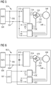
- FIG. 3 shows a system 302 including a generator 340 and a device according to a further embodiment of the present invention.
- the device comprises a full-bridge rectifier 310, a step-up transformer 321, and a PWM full-bridge converter 330.
- the transformer 321 comprises only one set of secondary windings which are connected to the input of rectifier 310 via wires 324.
- a line filter 328 is arranged between the transformer 321 and rectifier 310 in order to suppress harmonics.
- the generator 340 e.g. a wind turbine, comprises a stator and a rotor.
- the stator comprises two sets (a first set and a second set) of stator windings.
- the primary side of the transformer 321 is connected to the first set of stator windings via wires 322 and the second set of stator windings is connected to the input of converter 331 via wires 346.
- the output of the rectifier 310 and the output of the converter 331 are connected in parallel to an input of a HVDC transmission system 390.
- Further similar devices and generators 340 can be connected to the HVDC transmission system via wires 392 and 394.
- the working principle and advantages of this embodiment are similar to those of the embodiment shown in Figure 1 .
- the converter 331 in this embodiment is connected to a second set of stator windings (instead of a second set of transformer secondary windings as in Figure 1 ). Accordingly, the converter 331 generates control currents and/or control voltages in the second set of stator windings, such that the control system (not shown) of the converter 331 has to be designed accordingly.
- the suppression of harmonics is handled by the line filter 328 in this embodiment, as the active converter 321 cannot influence the transformer 321 in this embodiment.
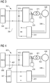
- FIG. 4 shows a system 403 including a generator 440 and a device according to a further embodiment of the present invention.
- the overall structure and function of this embodiment is similar to that of the embodiment shown in Figure 3 and described above.
- the output from rectifier 410 is connected to HVDC transmission system 490 while the output from converter 431 is connected to a LVDC system 491 having a significantly lower voltage than the HVDC system 490.
- the LVDC system 491 may be a separate system, such as a rectified DC voltage from the low voltage side of a wind turbine system or a dedicated low voltage generator (such as a gas turbine) or linked to the HVDC system 490, i.e. a split HVDC.
- the converter 431 is designed to operate at correspondingly lower voltages and the second set of stator windings is designed accordingly.
- Figure 5 shows a system 504 including a generator 540 and a device according to a further embodiment of the present invention. More specifically, this embodiment is a combination of the embodiments shown in Figures 1 and 3 . That is, the transformer 520 comprises two sets of secondary windings: one connected to the input of rectifier 510 via wires 524 and one connected to the input of a first PWM full-bridge converter 530 via wires 526. Furthermore, the generator 540 comprises two sets of stator windings: one connected to the primary set of windings of transformer 520 via wires 522 and one connected to the input of a second converter 531. The outputs of rectifier 530 and the two converters 530, 531 are connected in parallel to the input of HVDC transmission system 590.
- the first converter 530 corresponds (in design and function) to the converter 130 shown in Figure 1 and the second converter 531 similarly corresponds to the converter 331 shown in Figure 3 . That is, in this embodiment no line filter (corresponding to line filter 328, 428) is necessary, as the first converter 530 can handle the suppression of harmonics generated by the rectifier 510.
- FIG. 6 shows a system 605 including a generator and a device according to a further embodiment of the present invention. More specifically, this embodiment is a combination of the embodiments shown in Figures 2 and 4 . Accordingly, the overall structure and function of this embodiment is similar to that of the embodiment shown in Figure 5 and described above. However, in this embodiment, the output from rectifier 610 is connected to HVDC transmission system 690 while the outputs from the first converter 630 and second converter 631 are connected in parallel to a LVDC system 691 having a significantly lower voltage than the HVDC system 690. Like in the embodiments of Figures 2 and 4 , the LVDC system 691 may be a separate system or linked to the HVDC system 690. Accordingly, the converters 630 and 631 are designed to operate at correspondingly lower voltages and lower power, and the second sets of secondary windings and stator windings are designed accordingly.
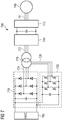
- FIG. 7 shows a system including a generator 740 and a device according to a further embodiment of the present invention.
- This embodiment corresponds to the embodiment of Figure 1 with some additional features on the generator side.
- the AC output from generator 740 is fed to generator converter 742 via wires 741.
- the resulting DC output from generator converter 742 is input to a selectable frequency grid converter 744 which provides a 3-phase AC output with a selected frequency to the primary side of transformer 720.
- Rectifier 710, transformer 720 and converter 730 correspond to rectifier 110, transformer 120 and converter 130 shown in Figure 1 and described in detail above.
- an alternative frequency e.g., 30Hz or 70Hz
- a higher frequency may be more suitable within a wind farm.
- the flexibility in selection of the frequency provides various benefits in terms of cost, size and performance of the system.
Landscapes
- Engineering & Computer Science (AREA)
- Power Engineering (AREA)
- Control Of Eletrric Generators (AREA)
Description
- The present invention relates to the field of electrical power production, in particular to devices and methods for connecting electric power generators to an HVDC transmission system.
- With the development of large offshore wind farms for producing electric energy, transmission losses occurring along transmission lines between a wind farm and a connection to a distribution grid on land may become significant.
- In such cases, HVDC (high-voltage, direct current) technology has distinct advantages in terms of low losses in comparison to the common AC (alternating current) technologies. In particular, by using a high voltage (up to e.g. 800 kV), the current flowing in the transmission lines - and thereby the resistive losses - is significantly reduced when a given amount of power is transmitted. Thus, in terms of losses, HVDC is preferable for long distance power transmission and may be considered as being ideal for offshore wind power applications. The use of fewer number of wires for transmission also means reduction in costs.
- However, in order to handle the high voltage and high power in the HVDC transmission, especially under increasingly stringent performance requirements, some sophisticated power converter systems have to be applied, which can be technically challenging and often means high cost.
- In known implementations, the AC output of a grid converter of a wind turbine is connected to a step-up transformer, and then converted to HVDC through a converter. Two of the common converter topologies are line-commutated current source Thyristor converters and IGBT based voltage source converters (VSCs).
- Thyristor converter systems have been the dominant technique for HVDC transmission, which can use voltages as high as 800kV. In this converter type, the firing angle is used for control of the DC voltage and the power flow. It consumes reactive power and the AC currents contain low-frequency harmonics. Thus, phase compensation is normally used to improve the power factor, and large filters are required to reduce the current distortion.
- The HVDC transmission with VSC technique has the advantages of high control bandwidth and low current harmonic distortion, and thus low requirements on the line filters. This kind of system is in fast progress, and two examples are Siemens HVDC Plus and ABB HVDC Light. Both systems employ multilevel converter techniques in order to accommodate low voltage rated power components (e.g., IGBT) and relatively low switching operations, and hence the systems tend to be relatively more technically challenging and more expensive.
- There may be a need for a simple and cost-effective way of connecting an electrical power generator to an HVDC transmission system.
- Document
CN102222929 discloses a device for connecting an electric power generator to an HVDC transmission system, the device comprising: a first unit for converting an AC output voltage from the electric power generator to a DC input voltage for the HVDC transmission system, the first unit comprising a transformer and a full-bridge rectifier, and a second unit for generating control voltages and/or control currents in the transformer and/or in the electric power generator, the second unit comprising a PWM full-bridge converter adapted to receive the AC output voltage from the electric power generator or an AC voltage based on said AC output voltage. DocumentEP1787383 discloses a similar device. - This need may be met by the subject matter according to the independent claims. Advantageous embodiments of the present invention are described by the dependent claims.
- According to a first aspect of the invention there is provided a device according to claim 1. Further, a method according to claim 8 is provided.
- This aspect of the invention is based on the idea that the connection between the electric power generator and the HVDC transmission system is split up in a first path (formed by the first unit) and a second path (formed by the second unit). The first path serves to convert the AC output voltage from the electric power generator to a suitable DC input voltage for the HVDC transmission system, i.e. the first unit comprises a transformer for increasing the AC voltage and a full-bridge rectifier that rectifies the increased AC voltage level to the DC input voltage for the HVDC transmission system. Thus, the first unit handles the actual (or main) transmission of electric power from the electric power generator into the HVDC transmission system. The second path serves to generate control/voltages and/or control currents, i.e. the second unit comprises a PWM full-bridge converter that is dedicated to performing control and correction functions rather than power transmission. In other words, the power transmission is handled by the simple and cost-effective full-bridge rectifier of the first unit, while control and correction functions are handled by a PWM full-bridge converter. As the PWM full-bridge converter of the second unit will not have to handle the same level of power as the full-bridge rectifier of the first unit, the PWM full-bridge converter of the second unit does not need to be nearly as complex (and thus expensive) as a PWM full-bridge converter designed to handle both power transmission and control functions. Accordingly, the device according to this aspect of the present invention provides a simple and cost-effective way of the feeding power from an electric power generator, such as an offshore wind turbine or wind farm, into a HVDC transmission system.
- In the present context, the term "full-bridge rectifier" may in particular denote a rectifier utilizing passive components, while the term "PWM full-bridge converter" in particular may denote a converter utilizing active components.
- The PWM full-bridge converter of the second unit is adapted to receive the AC output voltage from the electric power generator or an AC voltage based on (or derived from) the AC output voltage from the electric power generator. In the latter case, the PWM full-bridge converter may e.g. receive the AC voltage via a transformer that raises the voltage compared to the AC output voltage from the electric power generator.
- According to the invention, the transformer comprises (a) a set of primary windings for receiving the AC output voltage from the electric power generator, (b) a first set of secondary windings coupled to an input of the full-bridge rectifier of the first unit, and (c) a second set of secondary windings coupled to an input of the PWM full-bridge converter of the second unit.
- The relation between the number of turns in the first set of secondary windings and the number of turns in the set of primary windings is chosen in view of the AC output voltage from the electric power generator such that the rectified DC output voltage of the full-bridge rectifier of the first unit corresponds to the required DC input voltage of the HVDC transmission system, e.g. such that a 690 V AC output voltage is converted to an 800 kV DC voltage.
- Similarly, the relation between the number of turns in the second set of secondary windings and the number of turns in the set of primary windings is chosen in view of the AC output voltage from the electric power generator and the DC voltage at the output of the PWM full-bridge converter.
- The number of turns in the second set of secondary windings may be equal to or less than the number of turns in the first set of secondary windings.
- The AC output voltage from the electric power generator may preferably be a 3-phase AC voltage. In this case, each of the set of primary windings, the first set of secondary windings and the second set of secondary windings may preferably comprise 3 windings, i.e. one winding per phase.
- In this embodiment, the two (i.e. first and second) sets of secondary windings of the transformer splits the output power from the electric power generator into a first part that is provided to the first unit and into a second part that is provided to the second unit.
- Accordingly, this embodiment differs from a conventional HVDC connection device in that the transformer is provided with a second set of secondary windings sharing the same core as the first set of secondary windings, and in that the second set of secondary windings are coupled to a converter that is dedicated to generating control voltages and/or control currents in the transformer, e.g. for harmonic control, efficiency control, HVDC voltage regulation etc.
- Thus, the present embodiment is easy to implement in existing systems without modification of the electric power generator.
- According to the invention, the electric power generator comprises a generator unit having a stator and a rotatably supported rotor, the stator comprising a first set of windings and a second set of windings, the rotor being adapted to induce electrical voltage in the first set of windings and in the second set of windings when the rotor is rotated relative to the stator. Furthermore, the set of primary windings of the transformer of the first unit is coupled to the first set of windings of the stator, and the second unit comprises a further PWM full-bridge converter having an input coupled to the second set of windings of the stator.
- In other words, the second unit comprises two PWM full-bridge converters, i.e. converter one coupled to the second set of secondary windings of the transformer of the first unit as described above, and a further converter coupled to the second set of windings of the stator.
- The further PWM full-bridge converter may in particular be dedicated to generation of control voltages and/or control currents for the generator unit, i.e. to perform control and regulation functions relating to the output from the generator unit, while the other (i.e. the first) PWM full-bridge converter (i.e. the one coupled to the second set of secondary windings of the transformer of the first unit) may be dedicated to generation of control voltages and/or control currents for the transformer as described above.
- By using two separate PWM full-bridge converters, one for controlling the generator unit and one for controlling the transformer, the control may be optimized and each of the two converters may be designed to handle even less power than in the above described embodiment with a single PWM full-bridge converter. Furthermore, as the output voltage to the full-bridge rectifier of the first unit can be regulated by use of both PWM converters (i.e. in the generator and transformer), the HVDC may be better matched across multiple generators, such as multiple wind turbines in a wind farm.
- The generator unit may be a permanent magnet machine, an externally excited synchronous machine, an induction machine, a switched reluctance machine, etc. In particular, the generator unit may be a permanent magnet machine for a direct drive wind turbine.
- According to a further embodiment of the invention, the electric power generator comprises a selectable frequency grid converter for providing the AC output voltage.
- Thereby, instead of the conventional frequency of 50Hz or 60Hz for operation in the grid connection, an alternative frequency (e.g., 30Hz or 70Hz) can be selected. For example, as the AC power will be fairly local, and the impedance and losses for long distance transmission are not much of a concern, a higher frequency may be more suitable within a wind farm. The flexibility in selection of the frequency may provide some benefits in terms of cost, size and performance of the system.
- According to a further embodiment of the invention, the electric power generator comprises a generator unit having a stator and a rotatably supported rotor, the stator comprising a first set of windings and a second set of windings, the rotor being adapted to induce electrical voltage in the first set of windings and in the second set of windings when the rotor is rotated relative to the stator. The transformer of the first unit comprises: (a) a set of primary windings coupled to the first set of windings of the stator in order to receive the AC output voltage from the electric power generator, and (b) a set of secondary windings coupled to an input of the full-bridge rectifier of the first unit. Furthermore, an input of the PWM full-bridge converter of the second unit is coupled to the second set of windings of the stator.
- In this embodiment, the input of the PWM full-bridge converter of the second unit is coupled to the second set of windings of the stator. Thus, in comparison to the embodiment described above, the transformer of the first unit does not have to have a second set of secondary windings. However, the general idea remains the same: The PWM full-bridge converter of the second unit is responsible for generating control voltages and/or control currents while the full-bridge rectifier of the first unit is responsible for the actual transmission of power to the HVDC transmission system. However, apart from the advantages described with regard to the above described embodiment, this arrangement or topology may be less costly and more efficient. A line filter may have to be used for suppression of harmonics generated by the full-bridge rectifier of the first unit. Furthermore, the transformer may have to be somewhat over-sized due to the relatively low operating frequencies.
- It should also be noted, that in all embodiments where the generator unit comprises two sets (a first set and a second set) of stator windings, the PWM full-bridge converter of the second unit may be used to perform a wide variety of control functions, such as (a) a sensorless field orientated vector control, (b) Id current control for field weakening or field strengthening in the stator, (c) DC output voltage regulation (either directly or through field control), (d) active and reactive power control (either directly or through field control), (e) harmonic current control to compensate for the harmonics produced from the rectifier commutations, (f) torque ripple or vibration control by injection of harmonic currents, (g) cogging torque control, (h) generator power factor control or efficiency control by field regulation in the second system, and (i) various other control functions, such as drive-train damping control and support for grid fault conditions.
- According to the invention, an output of the PWM full-bridge converter is coupled to the HVDC transmission system or to a DC voltage system having a lower DC voltage than the HVDC transmission system.
- In the first case, where the output of the PWM full-bridge converter is coupled to the HVDC transmission system, the converter is designed to provide the same DC output voltage as the full-bridge rectifier of the first unit.
- In the second case, where the output of the PWM full-bridge converter is coupled to a DC voltage system having a lower DC voltage than the HVDC transmission system, the converter is designed to provide a corresponding DC output voltage. The DC voltage system may be provided as a voltage divider connected to the HVDC transmission system or as a separate DC voltage system, such as a rectified LVDC (low-voltage DC) from the low voltage side of a wind turbine system, or a dedicated low voltage generator (e.g, gas turbine(s)).
- According to a further embodiment of the invention, the control voltages and/or control currents generated by the second unit are adapted for at least one of DC output voltage regulation, active and reactive power control, and harmonic current control.
- According to a further embodiment of the invention, the full-bridge rectifier of the first unit is a full-bridge thyristor or diode rectifier and/or the PWM full-bridge converter of the second unit is a voltage source full-bridge type converter.
- Thereby, the full-bridge rectifier, which is dedicated to transmitting power into the HVDC transmission system, can be made of simple, reliable and relatively inexpensive passive components, while the PWM full-bridge type converter, which is dedicated to generating control voltages and/or control currents, can be made of active semiconductor components, such as e.g. IGBTs, that do not need the capability of handling the large amount of power transmitted to the HVDC transmission system but only the power concerned with the relevant control functions.
- According to a second aspect of the invention, there is provided a system for producing electric power and feeding it to an HVDC transmission system, the system comprising (a) an electric power generator, and (b) a device according to the first aspect or any of the above embodiments.
- This aspect of the invention is based on substantially the same idea as the first aspect described above. More specifically, this aspect of the invention relates to a system for producing electric power with the ability of feeding said power to an HVDC transmissions system by means of a device according to the first aspect or any of the above embodiments.
- According to a further embodiment of the invention, the electric power generator comprises a wind turbine.
- In particular, the system may be constituted by an offshore wind farm comprising a plurality of wind turbines.
- The method of claim 8 is based on substantially the same idea as the first aspect described above.
- Generally, in embodiments of the present invention, the power flow in an HVDC system may be separated into two paths: one with high voltage and one with low voltage. The high voltage and high power will be handled by simple converters, such as Thyristor or diode based rectifiers (mostly passive), and the low voltage and low power path is mainly composed of voltage source converters (VSC) for active control, such as reactive power compensation and HVDC voltage balancing, etc. Associated with the active control path, auxiliary windings are included in the generator and/or the transformer. As discussed above, such an HVDC system is less expensive and more reliable, whilst the performance for each individual wind turbine and their HVDC bus interconnection is retained.
- Or stated otherwise: This invention aims at creating an alternative HVDC topology. The core of the new topology is to allow the main power to flow through passive or low switching HVDC/MVDC converter system, while keeping the converters for active control at low voltage levels. Hence, in the high voltage path, simple power components (such as Thyristors or diodes) can be used, where the technology is relatively matured, and the resultant converter will be more reliable and energy efficient, but less expensive. The auxiliary parts are operated at low voltage for active control of power flow, as well as some critical functions such as voltage balancing across generators (e.g. wind turbines).
- It is noted that embodiments of the invention have been described with reference to different subject matters. In particular, some embodiments have been described with reference to method type claims whereas other embodiments have been described with reference to apparatus type claims. However, a person skilled in the art will gather from the above and the following description that, unless otherwise indicated, in addition to any combination of features belonging to one type of subject matter also any combination of features relating to different subject matters, in particular to combinations of features of the method type claims and features of the apparatus type claims, is part of the disclosure of this document.
- The aspects defined above and further aspects of the present invention are apparent from the examples of embodiments to be described hereinafter and are explained with reference to the examples of embodiments. The invention will be described in more detail hereinafter with reference to examples of embodiments. However, it is explicitly noted that the invention is not limited to the described exemplary embodiments.
-
-
Figure 1 shows a device according to an embodiment. -
Figure 2 shows a device according to a further embodiment. -
Figure 3 shows a system including a generator and a device according to a further embodiment. -
Figure 4 shows a system including a generator and a device according to a further embodiment. -
Figure 5 shows a system including a generator and a device according to a further embodiment of the present invention. -
Figure 6 shows a system including a generator and a device according to a further embodiment of the present invention. -
Figure 7 shows a system including a generator and a device according to a further embodiment. - The illustration in the drawing is schematic. It is noted that in different figures, similar or identical elements are provided with the same reference numerals or with reference numerals which differ only within the first digit.
-
Figure 1 shows adevice 100 according to an embodiment of the present invention. Thedevice 100 comprises a full-bridge rectifier 110, a step-uptransformer 120, and a PWM full-bridge converter 130. The full-bridge rectifier 110 comprises six diodes (or thyristors) arranged to rectify a 3-phase AC input into an output DC voltage. The PWM full-bridge converter 130 is an active converter comprising semiconductor switching components (e.g. IGBTs) and a control circuit (not shown) for converting a 3-phase AC input into an output DC voltage while generating control currents and/or control voltages in thetransformer 120. Thetransformer 120 comprises a set of 3 primary windings that is connectable to a 3-phase AC output from a generator, such as one or more wind turbines, viawires 122. Thetransformer 120 further comprises a first set of 3 secondary windings connected to the input of therectifier 110 viawires 124 and a second set of 3 secondary windings connected to the input of theconverter 130 viawires 126. In this embodiment, the two sets of secondary windings of thetransformer 120 comprise slightly different numbers of turns, such that therectifier 110 receives a slightly higher AC voltage than theconverter 130. Therectifier 110 andconverter 130 provide substantially the same DC voltage at their respective outputs. The output of therectifier 110 and the output of theconverter 130 are connected in parallel to an input of aHVDC transmission system 190. - In operation, the step-up
transformer 120 receives a 3-phase AC voltage (e.g. 690 V) from a generator (e.g. one or more wind turbines) viawires 122 and transforms it to substantially higher voltage levels for input to therectifier 110 viawires 124 and to theconverter 130 viawires 126. Therectifier 110 provides a corresponding rectified DC output voltage (e.g. 800 kV) and feeds it to theHVDC transmission system 190. At the same time, theconverter 130 generates control currents and/or control voltages in thetransformer 120 in order to perform control functions, such as active control of power flow, voltage balancing across generators (e.g. wind turbines), generation of active/reactive power, output voltage regulation, etc. Thereby, therectifier 110 handles the actual transmission of power to theHVDC transmission system 190, while theconverter 130 handles the generation of control currents and/or control voltages. Accordingly, theconverter 130 must not handle the large power levels that are handled by therectifier 110 and can thus be designed with relatively cheap components in comparison to a stand-alone active converter designed to handle both actual power transmission and control functions. -
Figure 2 shows adevice 201 according to a further embodiment of the present invention. The overall structure and function of thedevice 201 is similar to that of thedevice 100 which is shown inFigure 1 and described above. However, thedevice 201 differs fromdevice 100 in that the output fromrectifier 210 andconverter 230 are not connected in parallel. Instead, the output fromrectifier 210 is connected toHVDC transmission system 290 while the output fromconverter 230 is connected to aLVDC system 291 having a significantly lower voltage (e.g. 1100V) than theHVDC system 290. TheLVDC system 291 may be a separate system, such as a rectified DC voltage from the low voltage side of a wind turbine system or a dedicated low voltage generator (such as a gas turbine) or linked to theHVDC system 290, i.e. a split HVDC. Accordingly, theconverter 230 is designed to operate at correspondingly lower voltages and the number of turns in the second set of secondary windings oftransformer 220 is chosen accordingly. Thereby, theconverter 230 can be realized with even cheaper components than theconverter 130, as it does not need to handle the high voltages. -
Figure 3 shows asystem 302 including agenerator 340 and a device according to a further embodiment of the present invention. Like in the embodiments described above, the device comprises a full-bridge rectifier 310, a step-uptransformer 321, and a PWM full-bridge converter 330. However, in this embodiment, thetransformer 321 comprises only one set of secondary windings which are connected to the input ofrectifier 310 viawires 324. Aline filter 328 is arranged between thetransformer 321 andrectifier 310 in order to suppress harmonics. Thegenerator 340, e.g. a wind turbine, comprises a stator and a rotor. The stator comprises two sets (a first set and a second set) of stator windings. The primary side of thetransformer 321 is connected to the first set of stator windings viawires 322 and the second set of stator windings is connected to the input ofconverter 331 viawires 346.
Like inFigure 1 , the output of therectifier 310 and the output of theconverter 331 are connected in parallel to an input of aHVDC transmission system 390. Further similar devices andgenerators 340 can be connected to the HVDC transmission system viawires - In general, the working principle and advantages of this embodiment are similar to those of the embodiment shown in
Figure 1 . However, theconverter 331 in this embodiment is connected to a second set of stator windings (instead of a second set of transformer secondary windings as inFigure 1 ). Accordingly, theconverter 331 generates control currents and/or control voltages in the second set of stator windings, such that the control system (not shown) of theconverter 331 has to be designed accordingly. In particular, the suppression of harmonics is handled by theline filter 328 in this embodiment, as theactive converter 321 cannot influence thetransformer 321 in this embodiment. -
Figure 4 shows asystem 403 including agenerator 440 and a device according to a further embodiment of the present invention. The overall structure and function of this embodiment is similar to that of the embodiment shown inFigure 3 and described above. However, in this embodiment, the output fromrectifier 410 is connected toHVDC transmission system 490 while the output fromconverter 431 is connected to aLVDC system 491 having a significantly lower voltage than theHVDC system 490. TheLVDC system 491 may be a separate system, such as a rectified DC voltage from the low voltage side of a wind turbine system or a dedicated low voltage generator (such as a gas turbine) or linked to theHVDC system 490, i.e. a split HVDC. Accordingly, theconverter 431 is designed to operate at correspondingly lower voltages and the second set of stator windings is designed accordingly. -
Figure 5 shows asystem 504 including agenerator 540 and a device according to a further embodiment of the present invention. More specifically, this embodiment is a combination of the embodiments shown inFigures 1 and3 . That is, thetransformer 520 comprises two sets of secondary windings: one connected to the input ofrectifier 510 viawires 524 and one connected to the input of a first PWM full-bridge converter 530 viawires 526. Furthermore, thegenerator 540 comprises two sets of stator windings: one connected to the primary set of windings oftransformer 520 viawires 522 and one connected to the input of asecond converter 531. The outputs ofrectifier 530 and the twoconverters HVDC transmission system 590. - In this embodiment, the
first converter 530 corresponds (in design and function) to theconverter 130 shown inFigure 1 and thesecond converter 531 similarly corresponds to theconverter 331 shown inFigure 3 . That is, in this embodiment no line filter (corresponding toline filter 328, 428) is necessary, as thefirst converter 530 can handle the suppression of harmonics generated by therectifier 510. -
Figure 6 shows asystem 605 including a generator and a device according to a further embodiment of the present invention. More specifically, this embodiment is a combination of the embodiments shown inFigures 2 and4 . Accordingly, the overall structure and function of this embodiment is similar to that of the embodiment shown inFigure 5 and described above. However, in this embodiment, the output fromrectifier 610 is connected toHVDC transmission system 690 while the outputs from thefirst converter 630 andsecond converter 631 are connected in parallel to aLVDC system 691 having a significantly lower voltage than theHVDC system 690. Like in the embodiments ofFigures 2 and4 , theLVDC system 691 may be a separate system or linked to theHVDC system 690. Accordingly, theconverters -
Figure 7 shows a system including agenerator 740 and a device according to a further embodiment of the present invention. This embodiment corresponds to the embodiment ofFigure 1 with some additional features on the generator side. More specifically, the AC output fromgenerator 740 is fed togenerator converter 742 viawires 741. The resulting DC output fromgenerator converter 742 is input to a selectablefrequency grid converter 744 which provides a 3-phase AC output with a selected frequency to the primary side oftransformer 720.Rectifier 710,transformer 720 andconverter 730 correspond torectifier 110,transformer 120 andconverter 130 shown inFigure 1 and described in detail above. - In this embodiment, instead of the conventional frequency of 50Hz or 60Hz for operation in the grid connection, an alternative frequency (e.g., 30Hz or 70Hz) can be selected in the HVDC power transmission system. For example, as the AC power will be fairly local, and the impedance and losses for long distance transmission are not much of a concern, a higher frequency may be more suitable within a wind farm. The flexibility in selection of the frequency provides various benefits in terms of cost, size and performance of the system.
- It is noted that the term "comprising" does not exclude other elements or steps and the use of the articles "a" or "an" does not exclude a plurality. Also elements described in association with different embodiments may be combined. It is further noted that reference signs in the claims are not to be construed as limiting the scope of the claims.
Claims (8)
- A device for connecting an electric power generator to an HVDC transmission system (190, 290, 390, 490, 590, 690, 790), the device comprising
a first unit for converting an AC output voltage from the electric power generator to a DC input voltage for the HVDC transmission system, the first unit comprising a transformer (120, 220, 321, 421, 520, 620, 720) and a full-bridge rectifier (110, 210, 310, 410, 510, 610, 710), and
a second unit for generating control voltages and/or control currents in the transformer and/or in the electric power generator while the first unit converts the AC output voltage to the DC input voltage, the second unit comprising a PWM full-bridge converter (130, 230, 331, 431, 530, 531, 630, 631, 730) adapted to receive the AC output voltage from the electric power generator or an AC voltage based on said AC output voltage,
wherein the transformer of the first unit comprises a set of primary windings for receiving the AC output voltage from the electric power generator, a first set of secondary windings coupled to an input of the full-bridge rectifier of the first unit, and a second set of secondary windings coupled to an input of the PWM full-bridge converter of the second unit,
wherein an output of the PWM full-bridge converter is coupled to the HVDC transmission system or to a DC voltage system (291, 491, 691) having a lower DC voltage than the HVDC transmission system,
wherein the electric power generator comprises a generator unit (340, 440, 540, 640, 740) having a stator and a rotatably supported rotor, the stator comprising a first set of windings and a second set of windings, the rotor being adapted to induce electrical voltage in the first set of windings and in the second set of windings when the rotor is rotated relative to the stator,
wherein the set of primary windings of the transformer of the first unit is coupled to the first set of windings of the stator,
wherein the second unit comprises a further PWM full-bridge converter (531, 631) having an input coupled to the second set of windings of the stator, and
wherein an output of the further PWM full-bridge converter is coupled to the HVDC transmission system or to a DC voltage system (291, 491, 691) having a lower DC voltage than the HVDC transmission system. - The device according to claim 1, wherein the electric power generator comprises a selectable frequency grid converter (744) for providing the AC output voltage.
- The device according to claim 1,
wherein the electric power generator comprises a generator unit (340, 440, 540, 640, 740) having a stator and a rotatably supported rotor, the stator comprising a first set of windings and a second set of windings, the rotor being adapted to induce electrical voltage in the first set of windings and in the second set of windings when the rotor is rotated relative to the stator,
wherein the transformer of the first unit comprises:a set of primary windings coupled to the first set of windings of the stator in order to receive the AC output voltage from the electric power generator, anda set of secondary windings coupled to an input of the full-bridge rectifier of the first unit, andwherein an input of the PWM full-bridge converter of the second unit is coupled to the second set of windings of the stator. - The device according to any of the preceding claims,
wherein the control voltages and/or control currents generated by the second unit are adapted for at least one of DC output voltage regulation, active and reactive power control, and harmonic current control. - The device according to any of the preceding claims, wherein the full-bridge rectifier of the first unit is a full-bridge thyristor or diode rectifier and/or wherein the PWM full-bridge converter of the second unit is a voltage source full-bridge type converter.
- A system for producing electric power and feeding it to an HVDC transmission system, the system comprising
an electric power generator, and
a device according to any of the preceding claims. - The system according to the preceding claim, wherein the electric power generator comprises a wind turbine.
- A method of connecting an electric power generator to an HVDC transmission system, the method comprising
providing a first unit for converting an AC output voltage from the electric power generator to a DC input voltage for the HVDC transmission system, the first unit comprising a transformer and a full-bridge rectifier, and
providing a second unit for generating control voltages and/or control currents in the transformer and/or in the electric power generator while the first unit converts the AC output voltage to the DC input voltage, the second unit comprising a PWM full-bridge converter adapted to receive the AC output voltage from the electric power generator or an AC voltage based on said AC output voltage,
wherein the transformer of the first unit comprises a set of primary windings for receiving the AC output voltage from the electric power generator, a first set of secondary windings coupled to an input of the full-bridge rectifier of the first unit, and a second set of secondary windings coupled to an input of the PWM full-bridge converter of the second unit,
wherein an output of the PWM full-bridge converter is coupled to the HVDC transmission system or to a DC voltage system having a lower DC voltage than the HVDC transmission system,
wherein the electric power generator comprises a generator unit (340, 440, 540, 640, 740) having a stator and a rotatably supported rotor, the stator comprising a first set of windings and a second set of windings, the rotor being adapted to induce electrical voltage in the first set of windings and in the second set of windings when the rotor is rotated relative to the stator,
wherein the set of primary windings of the transformer of the first unit is coupled to the first set of windings of the stator,
wherein the second unit comprises a further PWM full-bridge converter (531, 631) having an input coupled to the second set of windings of the stator, and
wherein an output of the further PWM full-bridge converter is coupled to the HVDC transmission system or to a DC voltage system (291, 491, 691) having a lower DC voltage than the HVDC transmission system.
Priority Applications (3)
| Application Number | Priority Date | Filing Date | Title |
|---|---|---|---|
| EP14170792.7A EP2953228B1 (en) | 2014-06-02 | 2014-06-02 | Device and method for connecting an electric power generator to an HVDC transmission system |
| US14/710,069 US9577544B2 (en) | 2014-06-02 | 2015-05-12 | Device and method for connecting an electric power generator to an HVDC transmission system |
| CN201510294470.8A CN105322530B (en) | 2014-06-02 | 2015-06-02 | Device and method for power generator to be connected to HVDC transmission system |
Applications Claiming Priority (1)
| Application Number | Priority Date | Filing Date | Title |
|---|---|---|---|
| EP14170792.7A EP2953228B1 (en) | 2014-06-02 | 2014-06-02 | Device and method for connecting an electric power generator to an HVDC transmission system |
Publications (2)
| Publication Number | Publication Date |
|---|---|
| EP2953228A1 EP2953228A1 (en) | 2015-12-09 |
| EP2953228B1 true EP2953228B1 (en) | 2017-03-08 |
Family
ID=50897388
Family Applications (1)
| Application Number | Title | Priority Date | Filing Date |
|---|---|---|---|
| EP14170792.7A Not-in-force EP2953228B1 (en) | 2014-06-02 | 2014-06-02 | Device and method for connecting an electric power generator to an HVDC transmission system |
Country Status (3)
| Country | Link |
|---|---|
| US (1) | US9577544B2 (en) |
| EP (1) | EP2953228B1 (en) |
| CN (1) | CN105322530B (en) |
Families Citing this family (11)
| Publication number | Priority date | Publication date | Assignee | Title |
|---|---|---|---|---|
| US9571022B2 (en) * | 2013-08-30 | 2017-02-14 | Abb Schweiz Ag | Electrical generator with integrated hybrid rectification system comprising active and passive rectifiers connected in series |
| US9941827B2 (en) | 2016-06-08 | 2018-04-10 | Hamilton Sundstrand Corporation | High voltage DC power generating system including selectively removable neutral node |
| EP3393036A1 (en) * | 2017-04-20 | 2018-10-24 | ABB Schweiz AG | Power generation systemtechnical field |
| EP3599715B1 (en) * | 2018-07-26 | 2022-08-24 | Siemens Gamesa Renewable Energy A/S | Assessing wind turbine generator rotor temperature |
| ES2928722T3 (en) * | 2018-08-29 | 2022-11-22 | General Electric Renovables Espana Sl | Wind Turbine Hub Rotation Procedures |
| US10971934B2 (en) | 2018-12-31 | 2021-04-06 | Abb Schweiz Ag | Distribution networks with flexible direct current interconnection system |
| US11121543B2 (en) | 2018-12-31 | 2021-09-14 | Abb Schweiz Ag | Fault mitigation in medium voltage distribution networks |
| US10819112B1 (en) | 2019-03-27 | 2020-10-27 | Abb Schweiz Ag | Feeder line fault response using direct current interconnection system |
| US11031773B2 (en) | 2019-03-27 | 2021-06-08 | Abb Power Grids Switzerland Ag | Transformer isolation response using direct current link |
| WO2020236145A1 (en) * | 2019-05-20 | 2020-11-26 | Huawei Technologies Co., Ltd. | Hybrid power conversion system and method |
| CN114268111B (en) * | 2022-03-03 | 2022-06-03 | 东方博沃(北京)科技有限公司 | Zero-crossing detection method, device, equipment and storage medium |
Family Cites Families (10)
| Publication number | Priority date | Publication date | Assignee | Title |
|---|---|---|---|---|
| US6713889B2 (en) * | 2001-04-27 | 2004-03-30 | Siemens Aktiengesellschaft | Motor-generator system for a motor vehicle with hybrid traction drive |
| GB2418079B (en) * | 2004-09-10 | 2007-12-12 | Areva T & D Uk Ltd | Convertible high voltage direct current installation |
| US8373372B2 (en) * | 2009-09-25 | 2013-02-12 | Ut-Battelle, Llc | Electrical motor/generator drive apparatus and method |
| ES2466353T3 (en) * | 2010-04-08 | 2014-06-10 | Alstom Technology Ltd. | HVDC Hybrid Transformer |
| US20120126758A1 (en) * | 2010-11-19 | 2012-05-24 | Hamilton Sundstrand Corporation | High voltage dc power generation |
| EP2492501B1 (en) * | 2011-02-25 | 2017-04-12 | Siemens Aktiengesellschaft | Wind turbine |
| CN102222929B (en) * | 2011-06-24 | 2014-04-30 | 梁一桥 | DC (Direct Current) power transmission system with function of unidirectionally transmitting power |
| US20130234678A1 (en) * | 2012-03-06 | 2013-09-12 | Ciaran Patterson | Alternator ripple voltage reduction using output feedback to an independent field coil |
| CN102983586B (en) * | 2012-07-13 | 2016-01-20 | 中电普瑞科技有限公司 | A kind of HVDC based on three-level voltage source converter holds concurrently UPFC system |
| EP2940860B1 (en) * | 2014-04-29 | 2019-11-06 | Siemens Gamesa Renewable Energy A/S | Generator for producing electric power |
-
2014
- 2014-06-02 EP EP14170792.7A patent/EP2953228B1/en not_active Not-in-force
-
2015
- 2015-05-12 US US14/710,069 patent/US9577544B2/en active Active
- 2015-06-02 CN CN201510294470.8A patent/CN105322530B/en not_active Expired - Fee Related
Non-Patent Citations (1)
| Title |
|---|
| None * |
Also Published As
| Publication number | Publication date |
|---|---|
| EP2953228A1 (en) | 2015-12-09 |
| US20150349655A1 (en) | 2015-12-03 |
| CN105322530A (en) | 2016-02-10 |
| CN105322530B (en) | 2019-08-06 |
| US9577544B2 (en) | 2017-02-21 |
Similar Documents
| Publication | Publication Date | Title |
|---|---|---|
| EP2953228B1 (en) | Device and method for connecting an electric power generator to an HVDC transmission system | |
| US8957544B2 (en) | Systems and methods to optimize outputs of static inverters in variable energy generation environments | |
| US9837824B2 (en) | Connection system for power generation system with DC output | |
| US9525284B2 (en) | Medium voltage DC collection system with power electronics | |
| DK1553689T3 (en) | Rectifier circuit for generators with dynamic variable output power | |
| US9577557B2 (en) | Turbine-generator system with DC output | |
| AU2010353929B2 (en) | Converting device of electrical energy | |
| CN105048905B (en) | Generator for generating electric power | |
| US9611836B2 (en) | Wind turbine power conversion system | |
| EP2256915B1 (en) | Electric energy feedback device | |
| KR20120081170A (en) | An electrial power conversion system and method | |
| CN102568799B (en) | Phase-shift transformer and electric energy transmission device with same | |
| JP2016123196A (en) | Power conversion device | |
| US12027940B2 (en) | Rectifier | |
| Nouri et al. | A new AC/DC converter for the interconnections between wind farms and HVDC transmission lines |
Legal Events
| Date | Code | Title | Description |
|---|---|---|---|
| PUAI | Public reference made under article 153(3) epc to a published international application that has entered the european phase |
Free format text: ORIGINAL CODE: 0009012 |
|
| AK | Designated contracting states |
Kind code of ref document: A1 Designated state(s): AL AT BE BG CH CY CZ DE DK EE ES FI FR GB GR HR HU IE IS IT LI LT LU LV MC MK MT NL NO PL PT RO RS SE SI SK SM TR |
|
| AX | Request for extension of the european patent |
Extension state: BA ME |
|
| 17P | Request for examination filed |
Effective date: 20151218 |
|
| RBV | Designated contracting states (corrected) |
Designated state(s): AL AT BE BG CH CY CZ DE DK EE ES FI FR GB GR HR HU IE IS IT LI LT LU LV MC MK MT NL NO PL PT RO RS SE SI SK SM TR |
|
| 17Q | First examination report despatched |
Effective date: 20160224 |
|
| GRAP | Despatch of communication of intention to grant a patent |
Free format text: ORIGINAL CODE: EPIDOSNIGR1 |
|
| INTG | Intention to grant announced |
Effective date: 20160929 |
|
| GRAS | Grant fee paid |
Free format text: ORIGINAL CODE: EPIDOSNIGR3 |
|
| GRAA | (expected) grant |
Free format text: ORIGINAL CODE: 0009210 |
|
| AK | Designated contracting states |
Kind code of ref document: B1 Designated state(s): AL AT BE BG CH CY CZ DE DK EE ES FI FR GB GR HR HU IE IS IT LI LT LU LV MC MK MT NL NO PL PT RO RS SE SI SK SM TR |
|
| REG | Reference to a national code |
Ref country code: GB Ref legal event code: FG4D |
|
| REG | Reference to a national code |
Ref country code: CH Ref legal event code: EP Ref country code: AT Ref legal event code: REF Ref document number: 874328 Country of ref document: AT Kind code of ref document: T Effective date: 20170315 |
|
| REG | Reference to a national code |
Ref country code: IE Ref legal event code: FG4D |
|
| REG | Reference to a national code |
Ref country code: DE Ref legal event code: R096 Ref document number: 602014007308 Country of ref document: DE |
|
| REG | Reference to a national code |
Ref country code: LT Ref legal event code: MG4D |
|
| REG | Reference to a national code |
Ref country code: NL Ref legal event code: MP Effective date: 20170308 |
|
| PG25 | Lapsed in a contracting state [announced via postgrant information from national office to epo] |
Ref country code: LT Free format text: LAPSE BECAUSE OF FAILURE TO SUBMIT A TRANSLATION OF THE DESCRIPTION OR TO PAY THE FEE WITHIN THE PRESCRIBED TIME-LIMIT Effective date: 20170308 Ref country code: HR Free format text: LAPSE BECAUSE OF FAILURE TO SUBMIT A TRANSLATION OF THE DESCRIPTION OR TO PAY THE FEE WITHIN THE PRESCRIBED TIME-LIMIT Effective date: 20170308 Ref country code: FI Free format text: LAPSE BECAUSE OF FAILURE TO SUBMIT A TRANSLATION OF THE DESCRIPTION OR TO PAY THE FEE WITHIN THE PRESCRIBED TIME-LIMIT Effective date: 20170308 Ref country code: GR Free format text: LAPSE BECAUSE OF FAILURE TO SUBMIT A TRANSLATION OF THE DESCRIPTION OR TO PAY THE FEE WITHIN THE PRESCRIBED TIME-LIMIT Effective date: 20170609 Ref country code: NO Free format text: LAPSE BECAUSE OF FAILURE TO SUBMIT A TRANSLATION OF THE DESCRIPTION OR TO PAY THE FEE WITHIN THE PRESCRIBED TIME-LIMIT Effective date: 20170608 |
|
| REG | Reference to a national code |
Ref country code: AT Ref legal event code: MK05 Ref document number: 874328 Country of ref document: AT Kind code of ref document: T Effective date: 20170308 |
|
| RAP2 | Party data changed (patent owner data changed or rights of a patent transferred) |
Owner name: SIEMENS AKTIENGESELLSCHAFT |
|
| PG25 | Lapsed in a contracting state [announced via postgrant information from national office to epo] |
Ref country code: SE Free format text: LAPSE BECAUSE OF FAILURE TO SUBMIT A TRANSLATION OF THE DESCRIPTION OR TO PAY THE FEE WITHIN THE PRESCRIBED TIME-LIMIT Effective date: 20170308 Ref country code: ES Free format text: LAPSE BECAUSE OF FAILURE TO SUBMIT A TRANSLATION OF THE DESCRIPTION OR TO PAY THE FEE WITHIN THE PRESCRIBED TIME-LIMIT Effective date: 20170308 Ref country code: BG Free format text: LAPSE BECAUSE OF FAILURE TO SUBMIT A TRANSLATION OF THE DESCRIPTION OR TO PAY THE FEE WITHIN THE PRESCRIBED TIME-LIMIT Effective date: 20170608 Ref country code: RS Free format text: LAPSE BECAUSE OF FAILURE TO SUBMIT A TRANSLATION OF THE DESCRIPTION OR TO PAY THE FEE WITHIN THE PRESCRIBED TIME-LIMIT Effective date: 20170308 Ref country code: LV Free format text: LAPSE BECAUSE OF FAILURE TO SUBMIT A TRANSLATION OF THE DESCRIPTION OR TO PAY THE FEE WITHIN THE PRESCRIBED TIME-LIMIT Effective date: 20170308 |
|
| PG25 | Lapsed in a contracting state [announced via postgrant information from national office to epo] |
Ref country code: NL Free format text: LAPSE BECAUSE OF FAILURE TO SUBMIT A TRANSLATION OF THE DESCRIPTION OR TO PAY THE FEE WITHIN THE PRESCRIBED TIME-LIMIT Effective date: 20170308 |
|
| REG | Reference to a national code |
Ref country code: CH Ref legal event code: NV Representative=s name: SIEMENS SCHWEIZ AG, CH Ref country code: CH Ref legal event code: PCOW Free format text: NEW ADDRESS: WERNER-VON-SIEMENS-STRASSE 1, 80333 MUENCHEN (DE) |
|
| PG25 | Lapsed in a contracting state [announced via postgrant information from national office to epo] |
Ref country code: RO Free format text: LAPSE BECAUSE OF FAILURE TO SUBMIT A TRANSLATION OF THE DESCRIPTION OR TO PAY THE FEE WITHIN THE PRESCRIBED TIME-LIMIT Effective date: 20170308 Ref country code: IT Free format text: LAPSE BECAUSE OF FAILURE TO SUBMIT A TRANSLATION OF THE DESCRIPTION OR TO PAY THE FEE WITHIN THE PRESCRIBED TIME-LIMIT Effective date: 20170308 Ref country code: AT Free format text: LAPSE BECAUSE OF FAILURE TO SUBMIT A TRANSLATION OF THE DESCRIPTION OR TO PAY THE FEE WITHIN THE PRESCRIBED TIME-LIMIT Effective date: 20170308 Ref country code: CZ Free format text: LAPSE BECAUSE OF FAILURE TO SUBMIT A TRANSLATION OF THE DESCRIPTION OR TO PAY THE FEE WITHIN THE PRESCRIBED TIME-LIMIT Effective date: 20170308 Ref country code: SK Free format text: LAPSE BECAUSE OF FAILURE TO SUBMIT A TRANSLATION OF THE DESCRIPTION OR TO PAY THE FEE WITHIN THE PRESCRIBED TIME-LIMIT Effective date: 20170308 Ref country code: EE Free format text: LAPSE BECAUSE OF FAILURE TO SUBMIT A TRANSLATION OF THE DESCRIPTION OR TO PAY THE FEE WITHIN THE PRESCRIBED TIME-LIMIT Effective date: 20170308 |
|
| PG25 | Lapsed in a contracting state [announced via postgrant information from national office to epo] |
Ref country code: PT Free format text: LAPSE BECAUSE OF FAILURE TO SUBMIT A TRANSLATION OF THE DESCRIPTION OR TO PAY THE FEE WITHIN THE PRESCRIBED TIME-LIMIT Effective date: 20170710 Ref country code: SM Free format text: LAPSE BECAUSE OF FAILURE TO SUBMIT A TRANSLATION OF THE DESCRIPTION OR TO PAY THE FEE WITHIN THE PRESCRIBED TIME-LIMIT Effective date: 20170308 Ref country code: PL Free format text: LAPSE BECAUSE OF FAILURE TO SUBMIT A TRANSLATION OF THE DESCRIPTION OR TO PAY THE FEE WITHIN THE PRESCRIBED TIME-LIMIT Effective date: 20170308 Ref country code: IS Free format text: LAPSE BECAUSE OF FAILURE TO SUBMIT A TRANSLATION OF THE DESCRIPTION OR TO PAY THE FEE WITHIN THE PRESCRIBED TIME-LIMIT Effective date: 20170708 |
|
| REG | Reference to a national code |
Ref country code: DE Ref legal event code: R097 Ref document number: 602014007308 Country of ref document: DE |
|
| PLBE | No opposition filed within time limit |
Free format text: ORIGINAL CODE: 0009261 |
|
| STAA | Information on the status of an ep patent application or granted ep patent |
Free format text: STATUS: NO OPPOSITION FILED WITHIN TIME LIMIT |
|
| PG25 | Lapsed in a contracting state [announced via postgrant information from national office to epo] |
Ref country code: MC Free format text: LAPSE BECAUSE OF FAILURE TO SUBMIT A TRANSLATION OF THE DESCRIPTION OR TO PAY THE FEE WITHIN THE PRESCRIBED TIME-LIMIT Effective date: 20170308 Ref country code: DK Free format text: LAPSE BECAUSE OF FAILURE TO SUBMIT A TRANSLATION OF THE DESCRIPTION OR TO PAY THE FEE WITHIN THE PRESCRIBED TIME-LIMIT Effective date: 20170308 |
|
| REG | Reference to a national code |
Ref country code: CH Ref legal event code: PL |
|
| 26N | No opposition filed |
Effective date: 20171211 |
|
| PG25 | Lapsed in a contracting state [announced via postgrant information from national office to epo] |
Ref country code: SI Free format text: LAPSE BECAUSE OF FAILURE TO SUBMIT A TRANSLATION OF THE DESCRIPTION OR TO PAY THE FEE WITHIN THE PRESCRIBED TIME-LIMIT Effective date: 20170308 |
|
| REG | Reference to a national code |
Ref country code: IE Ref legal event code: MM4A |
|
| REG | Reference to a national code |
Ref country code: FR Ref legal event code: ST Effective date: 20180228 |
|
| PG25 | Lapsed in a contracting state [announced via postgrant information from national office to epo] |
Ref country code: LI Free format text: LAPSE BECAUSE OF NON-PAYMENT OF DUE FEES Effective date: 20170630 Ref country code: LU Free format text: LAPSE BECAUSE OF NON-PAYMENT OF DUE FEES Effective date: 20170602 Ref country code: IE Free format text: LAPSE BECAUSE OF NON-PAYMENT OF DUE FEES Effective date: 20170602 Ref country code: CH Free format text: LAPSE BECAUSE OF NON-PAYMENT OF DUE FEES Effective date: 20170630 |
|
| PG25 | Lapsed in a contracting state [announced via postgrant information from national office to epo] |
Ref country code: FR Free format text: LAPSE BECAUSE OF NON-PAYMENT OF DUE FEES Effective date: 20170630 |
|
| REG | Reference to a national code |
Ref country code: BE Ref legal event code: MM Effective date: 20170630 |
|
| PG25 | Lapsed in a contracting state [announced via postgrant information from national office to epo] |
Ref country code: BE Free format text: LAPSE BECAUSE OF NON-PAYMENT OF DUE FEES Effective date: 20170630 |
|
| PG25 | Lapsed in a contracting state [announced via postgrant information from national office to epo] |
Ref country code: MT Free format text: LAPSE BECAUSE OF NON-PAYMENT OF DUE FEES Effective date: 20170602 |
|
| PG25 | Lapsed in a contracting state [announced via postgrant information from national office to epo] |
Ref country code: HU Free format text: LAPSE BECAUSE OF FAILURE TO SUBMIT A TRANSLATION OF THE DESCRIPTION OR TO PAY THE FEE WITHIN THE PRESCRIBED TIME-LIMIT; INVALID AB INITIO Effective date: 20140602 |
|
| REG | Reference to a national code |
Ref country code: DE Ref legal event code: R081 Ref document number: 602014007308 Country of ref document: DE Owner name: SIEMENS GAMESA RENEWABLE ENERGY A/S, DK Free format text: FORMER OWNER: SIEMENS AKTIENGESELLSCHAFT, 80333 MUENCHEN, DE |
|
| PG25 | Lapsed in a contracting state [announced via postgrant information from national office to epo] |
Ref country code: CY Free format text: LAPSE BECAUSE OF FAILURE TO SUBMIT A TRANSLATION OF THE DESCRIPTION OR TO PAY THE FEE WITHIN THE PRESCRIBED TIME-LIMIT Effective date: 20170308 |
|
| PG25 | Lapsed in a contracting state [announced via postgrant information from national office to epo] |
Ref country code: MK Free format text: LAPSE BECAUSE OF FAILURE TO SUBMIT A TRANSLATION OF THE DESCRIPTION OR TO PAY THE FEE WITHIN THE PRESCRIBED TIME-LIMIT Effective date: 20170308 |
|
| REG | Reference to a national code |
Ref country code: GB Ref legal event code: 732E Free format text: REGISTERED BETWEEN 20191128 AND 20191204 |
|
| PG25 | Lapsed in a contracting state [announced via postgrant information from national office to epo] |
Ref country code: TR Free format text: LAPSE BECAUSE OF FAILURE TO SUBMIT A TRANSLATION OF THE DESCRIPTION OR TO PAY THE FEE WITHIN THE PRESCRIBED TIME-LIMIT Effective date: 20170308 |
|
| PG25 | Lapsed in a contracting state [announced via postgrant information from national office to epo] |
Ref country code: AL Free format text: LAPSE BECAUSE OF FAILURE TO SUBMIT A TRANSLATION OF THE DESCRIPTION OR TO PAY THE FEE WITHIN THE PRESCRIBED TIME-LIMIT Effective date: 20170308 |
|
| PGFP | Annual fee paid to national office [announced via postgrant information from national office to epo] |
Ref country code: GB Payment date: 20210705 Year of fee payment: 8 Ref country code: DE Payment date: 20210819 Year of fee payment: 8 |
|
| REG | Reference to a national code |
Ref country code: DE Ref legal event code: R119 Ref document number: 602014007308 Country of ref document: DE |
|
| GBPC | Gb: european patent ceased through non-payment of renewal fee |
Effective date: 20220602 |
|
| PG25 | Lapsed in a contracting state [announced via postgrant information from national office to epo] |
Ref country code: GB Free format text: LAPSE BECAUSE OF NON-PAYMENT OF DUE FEES Effective date: 20220602 Ref country code: DE Free format text: LAPSE BECAUSE OF NON-PAYMENT OF DUE FEES Effective date: 20230103 |