EP2953211A1 - Procédé de conditionnement d'une section d'un élément d'accouplement - Google Patents
Procédé de conditionnement d'une section d'un élément d'accouplement Download PDFInfo
- Publication number
- EP2953211A1 EP2953211A1 EP14171160.6A EP14171160A EP2953211A1 EP 2953211 A1 EP2953211 A1 EP 2953211A1 EP 14171160 A EP14171160 A EP 14171160A EP 2953211 A1 EP2953211 A1 EP 2953211A1
- Authority
- EP
- European Patent Office
- Prior art keywords
- receiving chamber
- mating member
- cavity wall
- receiving
- insulation medium
- Prior art date
- Legal status (The legal status is an assumption and is not a legal conclusion. Google has not performed a legal analysis and makes no representation as to the accuracy of the status listed.)
- Withdrawn
Links
Images


Classifications
-
- H—ELECTRICITY
- H01—ELECTRIC ELEMENTS
- H01R—ELECTRICALLY-CONDUCTIVE CONNECTIONS; STRUCTURAL ASSOCIATIONS OF A PLURALITY OF MUTUALLY-INSULATED ELECTRICAL CONNECTING ELEMENTS; COUPLING DEVICES; CURRENT COLLECTORS
- H01R13/00—Details of coupling devices of the kinds covered by groups H01R12/70 or H01R24/00 - H01R33/00
- H01R13/46—Bases; Cases
- H01R13/52—Dustproof, splashproof, drip-proof, waterproof, or flameproof cases
- H01R13/523—Dustproof, splashproof, drip-proof, waterproof, or flameproof cases for use under water
-
- H—ELECTRICITY
- H01—ELECTRIC ELEMENTS
- H01R—ELECTRICALLY-CONDUCTIVE CONNECTIONS; STRUCTURAL ASSOCIATIONS OF A PLURALITY OF MUTUALLY-INSULATED ELECTRICAL CONNECTING ELEMENTS; COUPLING DEVICES; CURRENT COLLECTORS
- H01R13/00—Details of coupling devices of the kinds covered by groups H01R12/70 or H01R24/00 - H01R33/00
- H01R13/46—Bases; Cases
- H01R13/52—Dustproof, splashproof, drip-proof, waterproof, or flameproof cases
- H01R13/5219—Sealing means between coupling parts, e.g. interfacial seal
-
- H—ELECTRICITY
- H01—ELECTRIC ELEMENTS
- H01R—ELECTRICALLY-CONDUCTIVE CONNECTIONS; STRUCTURAL ASSOCIATIONS OF A PLURALITY OF MUTUALLY-INSULATED ELECTRICAL CONNECTING ELEMENTS; COUPLING DEVICES; CURRENT COLLECTORS
- H01R13/00—Details of coupling devices of the kinds covered by groups H01R12/70 or H01R24/00 - H01R33/00
- H01R13/46—Bases; Cases
- H01R13/53—Bases or cases for heavy duty; Bases or cases for high voltage with means for preventing corona or arcing
-
- H—ELECTRICITY
- H01—ELECTRIC ELEMENTS
- H01R—ELECTRICALLY-CONDUCTIVE CONNECTIONS; STRUCTURAL ASSOCIATIONS OF A PLURALITY OF MUTUALLY-INSULATED ELECTRICAL CONNECTING ELEMENTS; COUPLING DEVICES; CURRENT COLLECTORS
- H01R43/00—Apparatus or processes specially adapted for manufacturing, assembling, maintaining, or repairing of line connectors or current collectors or for joining electric conductors
- H01R43/002—Maintenance of line connectors, e.g. cleaning
Definitions
- the present invention relates to a method for conditioning at least a section of a mating member of a connector unit comprising the mating member and a corresponding receiving chamber with a cavity wall encasing a receiving cavity. Further, the present invention relates to the receiving chamber embodied to perform the inventive method, further to a connector part of a connector unit with a receiving chamber and to a use of the connector part in an undersea connector unit.
- a method for conditioning at least a section of a mating member of a connector unit comprising the mating member and a corresponding receiving chamber with a cavity wall partially encasing a receiving cavity is provided.
- the method comprises at least the steps of: Using a mating force caused by a mate of the mating member and the receiving chamber to force an insulation medium housed in the receiving cavity of the receiving chamber to travel along a distribution path for the insulation medium and conditioning at least the section of the mating member with the insulation medium while the insulation medium is bypassing the section of the mating member due to the mate of the mating member and the receiving chamber.
- any impurity in the insulation medium can be dispersed more evenly throughout the insulation medium by the mating process and much faster than by relying on the diffusion process like in current systems. Since the mating process drives the surface and insulation medium conditioning effect the conditioning flow and especially the cleaning flow, of the insulation medium will automatically adjust to the mating speed. Hence, a fast mating speed will include high flow rates which will in turn condition the surface faster. Additionally, by using the mating force as driving force for the insulation medium flow a special means for creating the flow of the insulation medium can be omitted, saving, space, mounting efforts and costs. Furthermore, an internal geometry of the receiving chamber can be optimised using computational dynamics to ensure that an optimal flow is created for any new connector design.
- a further advantage of the used flow path is that a solid insulation surrounding the receiving chamber, which forms the bulk of the insulation between the high voltage and earthed parts of the connector part, does not need to be broken or drilled to create flow ports for the insulation medium. This is because the insulation medium can be directed to flow out of the open end of the connector part through which the mating member enters. This is an advantage as any insulation medium flow port through the solid insulation would be electrical weak points in the system.
- a connector unit is intended to mean a unit which physically connects at least two parts, like two cables, preferably subsea cables, or a cable with a - subsea - module (e.g. a transformer, a pump etc.) or a busbar inside of the module or two modules, respectively. Thus, it is preferably a subsea connector unit.
- the connector unit may be used in any harsh environment and may be embodied as an electrical connector and/or penetrator or preferably as a wet mateable connector/penetrator. Moreover, it is preferably employed in a high voltage application.
- Such a connector unit comprises at least a conductor part that helps to establish an electrical connection in a mated position of two connected parts, like two cables or a cable with a module.
- This conductor part may be a conductor pin, receptacle pin or male part of a connector or of a penetrator or a socket contact of a female part, plug or socket or connector body of a connector for contacting a conductor pin of a male part.
- the connector unit comprises connector parts that are adapted to mate physically with each other and are for example embodied as a mating member or the male part and as a receiving chamber as a part of the female part.
- the connector part is embodied as the male part and/or as the female part.
- the receiving chamber in the female socket is intended to mean a part of the connector unit with an opening, recess, bore or cavity to receive another part of the connector unit, like the mating member (conductor pin) or parts thereof.
- the mating member is permanently connected to a cable or a module via a housing.
- the mating member is intended to mean a part of the unit with a pin, extension or the like to engage or being inserted in the receiving chamber of the female socket or the cable or the module.
- the mating member and its corresponding part are intended to establish an electrical connection either in case of mating of the male and female parts or a permanent connection of the conductor pin with the cable or module.
- the female and male parts or the module each may be encased in a casing or an external of a cable.
- a cavity wall should be understood as a structure being arranged at at least one side of the cavity and preferably at one axial side and around a circumference of the cavity.
- "partially encase” is intended to mean that not the whole cavity is surrounded by the cavity wall but that at least one section or opening in the cavity wall provides access to the cavity.
- An insulation medium is intended to mean any substance feasible for a person skilled in the art, like a silicone gel, grease, oil or preferably insulation medium.
- the insulation medium is used to protect and isolate internals and electrical contacts of e.g. the female part for example from salt water and debris as well as to support the mating of the female part with the male part of the connector unit. Thus, it has also lubricating properties.
- the insulation medium may be also a compensation medium due to its ability to react to pressure or thermal expansion and contraction.
- the term "housed in” should be understood as stored in or located in or that the receiving chamber is filled with the insulation medium.
- a “mating force” is intended to mean a force being applied or executed during the mate especially by the mating member and preferably it is the pushing force of the mating member acting either directly or indirectly (e.g. via a shuttle piston of the female part) on the insulation medium.
- a distribution path should be understood as a specially selected or embodied and predefined path for the insulation medium.
- a “conditioning” should be understood as a changing, modifying or and especially as a cleaning of the section of the mating member and especially as a removing of contaminations on the section.
- the section of the mating member is preferably a surface, especially a surface where creepage effects may occur or in short a creepage surface, wherein a creepage surface is a surface along which there is an electrical field.
- the section is preferably not located at a tip of the mating member and/or it is preferably not inserted in the receiving cavity of the receiving chamber. In other words, the section is preferably positioned outside of the receiving cavity of the receiving chamber after the mate of the mating member and the receiving chamber.
- the term “while bypassing” should be understood as “travelling along and simultaneously contacting”, wherein “contacting” should mean at least a physical contact or a physical interaction between the insulation medium and the section of the mating member.
- the inventive method is the idea of making use of the insulation medium, which flows through the connector unit during the mate by displacing the insulation medium due to an ingress of the mating member in the receiving chamber to condition a section e.g. a creepage surface of the mating member.
- the method comprises the step of: Forcing due to the mate of the mating member and the receiving chamber the insulation medium from the receiving cavity to exit through at least one radial aperture in the cavity wall of the receiving chamber.
- a controlled exit of the insulation medium can be provided.
- the method comprises the step of: Forcing due to the mate of the mating member and the receiving chamber the insulation medium to travel along at least one axial channel in an outer surface of the cavity wall of the receiving chamber. Due to this, the insulation medium flows along a defined, straight and direct path increasing the travel speed compared to an unrestricted flow path of the insulation medium.
- the method comprises the step of: Forcing due to the mate of the mating member and the receiving chamber the insulation medium from at least one axial channel in an outer surface of the cavity wall of the receiving chamber to enter the receiving cavity through at least one radial aperture in the cavity wall of the receiving chamber. Consequently, a direct entry for the insulation medium can be provided.
- the first and the at last second aperture as well as the axial channel are all parts of the distribution path.
- the method comprises the step of: Storing the insulation medium in a compensation volume in an electrically unstressed region of the connector unit after the conditioning of the section of the mating member.
- the majority of the insulation medium, which flows along the mating member ends up in a compensation volume outside of the receiving chamber (socket contact) where there is no electrical stress. Since the insulation medium with the embedded or dissolved contaminations is stored inside the compensation volume in the mated state of the connector unit the contaminations or impurity in the insulation medium can dispersed more evenly throughout the insulation medium. This results in a homogenous insulation medium for the subsequent conditioning and/or cleaning step during the subsequent mate. Generally, the capacity of the insulation medium to "store" impurities is about 30 mate and demate cycles.
- the method comprises the step of: Selecting a size and/or shape of at least one radial aperture in the cavity wall of the receiving chamber and/or a size and/or shape of an axial channel in an outer surface of the cavity wall of the receiving chamber and/or a size and/or shape of the cavity wall of the receiving chamber dependent on at least one physical property of the insulation medium.
- the physical property can be any parameter feasible for a person skilled in the art, like a flow rate, a density, a viscosity or a Reyn-olds number.
- a number of radial apertures and/or axial channel may be selected in dependency of at least one physical property of the insulation medium.
- the selection of the special embodiment(s) for a first structure of the above mentioned structures may be dependent on one or a group of physical properties of the insulation medium and in turn, the selection of the special embodiment(s) for another of the above mentioned structures may be dependent on another or a different group of physical properties of the insulation medium.
- the properties or characteristics of the above mentioned structures may also be selected in view of a range of mating speeds which are likely for the mate.
- a receiving chamber of a connector unit with a mating member and the receiving chamber comprising a receiving cavity and a cavity wall partially encasing the receiving cavity, is provided.
- an outer surface of the cavity wall comprises at least one channel extending in axial direction of the receiving cavity, a first radial aperture and at least a second radial aperture, wherein the first radial aperture is located at a first axial end of the at least one axial channel and wherein the at least second radial aperture is located at a second opposed from the first radial end located axial end of the at least one axial channel.
- a safe, reliable and failure proof receiving chamber and connector unit can be provided. This reduces also the chance of an unforeseen electrical breakdown due to a contaminated surface, especially of a creepage surface. Hence, a system with less electrical issues, compared with state of the art systems, may advantageously be provided. Moreover, the size and weight of the connector unit as well as the costs of the pieces and for an assembling can be reduced.
- the creepage surface and electrically stressed insulation medium are much cleaner when compared with current state of the art systems.
- Any impurity in the insulation medium can be dispersed more evenly throughout the insulation medium by the mating process and much faster than by relying on the diffusion process like in current systems. Since the mating process drives the surface and insulation medium conditioning effect the conditioning flow and/or cleaning flow of the insulation medium will automatically adjust to the mating speed. Hence, a fast mating speed will include high flow rates which will in turn condition the surface faster.
- a special means for creating the flow of the insulation medium can be omitted, saving, space, mounting efforts and costs.
- an internal geometry of the receiving chamber can be optimised using computational dynamics to ensure that an optimal flow is created for any new connector design.
- a further advantage of the used flow path is that a solid insulation surrounding the receiving chamber, which forms the bulk of the insulation between the high voltage and earthed parts of the connector part, does not need to be broken or drilled to create flow ports for the insulation medium. This is because the insulation medium can be directed to flow out of the open end of the connector part through which the mating member enters. This is an advantage as any insulation medium flow port through the solid insulation would be electrical weak points in the system.
- the first and second aperture may have any shape feasible for a person skilled in the art, like circular, rectangular, triangular, oval, egg-shaped etc. Preferably it is circular to provide a smooth and homogeneous exit and entry.
- a radial aperture is intended to mean an aperture which allows a flow in radial direction.
- the outer surface of the cavity wall comprises a plurality of axial channels, providing a sufficient surface area to distribute the insulation medium quickly and even during a high velocity mate.
- the axial channels are homogeneously distributed along an outer contour and/or preferably a circumference of the cavity wall. Hence, also the flow of insulation medium can be designed evenly.
- the cavity wall comprises a plurality of first radial apertures (exit apertures) to allow a great amount of insulation medium to exit the receiving chamber simultaneously.
- the cavity wall comprises a plurality of at least second radial apertures (entry apertures) to quickly discharge a high amount of insulation medium from the channel(s).
- the first radial apertures and/or the at least second radial apertures are homogeneously distributed along an outer contour and/or preferably a circumference of the cavity wall.
- a risk of an accumulation of insulation medium at one circumferential region of the receiving cavity or the channel(s) can be minimised.
- a partitioning of the plurality of axial channels is equal or an integer multiple of a partitioning of the plurality of the first radial apertures and/or of the at least second radial apertures. This provides an especially homogeneous distribution of the insulation medium along the distribution path.
- the outer surface of the cavity wall comprises at least one groove extending in circumferential direction of the cavity wall and wherein the first radial aperture is positioned at a bottom of the groove.
- the insulation medium can be easily feed to the channel(s).
- the at least second radial aperture is positioned at a bottom of the groove.
- the surface of the cavity wall comprises a first and at least a second circumferential grooves, wherein the first circumferential groove is located at the first axial end of the at least one axial channel and wherein the at least second circumferential groove is located at the second opposed from the first radial end located axial end of the at least one axial channel and wherein the plurality of the first apertures is positioned in the first circumferential groove and the plurality of the second apertures is positioned in the at least second circumferential groove.
- the first radial aperture and the at least second radial aperture are located axially aligned towards each other.
- the flow of the insulation medium can be designed evenly.
- the first radial aperture and the at least second radial aperture are arranged in an axial extension of a bottom of the axial channel allowing a straight and unhindered communication between the apertures and the axial channel.
- the first radial aperture and the at least second radial aperture are arranged in circumferential direction offset from an axial extension of a bottom of the at least tone axial channel.
- the at least one axial channel comprises two radial maxima and one radial minimum located between the two maxima and wherein the first radial aperture and the at least second radial aperture are located axially aligned with one radial maxima of the at least one axial channel.
- the cavity wall comprises an axial end region being located at a receiving opening of the receiving cavity and wherein the axial end region comprises an annulus region with an inner diameter that is smaller than an inner diameter of the receiving chamber.
- a connector part of a connector unit with a mating member comprising a first, a second and at least a third axial section, and with an inventive receiving chamber is provided.
- At least a first radial aperture in a cavity wall of the receiving chamber is located at an axial end of the first section of the mating member and wherein at least one axial channel in an outer surface of a cavity wall of the receiving chamber extends along the second and the at least third section of the mating member and wherein an at least second radial aperture in a cavity wall of the receiving chamber is located at an axial height where an axial end of the at least third section of the mating member, wherein the at the at least third section of the mating member comprises an insulating surface.
- a safe, reliable and failure proof receiving chamber and connector unit can be provided. This reduces also the chance of an unforeseen electrical breakdown due to a contaminated surface, especially of a creepage surface. Hence, a system with less electrical issues, compared with state of the art systems, may advantageously be provided. Moreover, the size and weight of the connector unit as well as the costs of the pieces and for an assembling can be reduced.
- the creepage surface and electrically stressed insulation medium are much cleaner when compared with current state of the art systems.
- Any impurity in the insulation medium can be dispersed more evenly throughout the insulation medium by the mating process and much faster than by relying on the diffusion process like in current systems. Since the mating process drives the surface and insulation medium conditioning effect the conditioning flow and especially the cleaning flow of the insulation medium will automatically adjust to the mating speed. Hence, a fast mating speed will include high flow rates which will in turn condition the surface faster.
- a special means for creating the flow of the insulation medium can be omitted, saving, space, mounting efforts and costs.
- an internal geometry of the receiving chamber can be optimised using computational dynamics to ensure that an optimal flow is created for any new connector design.
- a further advantage of the used flow path is that a solid insulation surrounding the receiving chamber, which forms the bulk of the insulation between the high voltage and earthed parts of the connector part, does not need to be broken or drilled to create flow ports for the insulation medium. This is because the insulation medium can be directed to flow out of the open end of the connector part through which the mating member enters. This is an advantage as any insulation medium flow port through the solid insulation would be electrical weak points in the system.
- the first section of the mating member is preferably a tip out of a corrosion resistant material.
- the second section is preferably a conducting portion, e.g. a copper section, to electrically contact the socket contact of the female part.
- the insulating surface of the third section is a creepage surface and the insulating surface may be out of any insulating material suitable for a person skilled in the art, and be for example a plastic material e.g. out of the polyaryletherketone (PAEK) family, like polyether ether ketone (PEEK) Epoxy family or the polyamide family (e.g. Nylon).
- PAEK polyaryletherketone
- PEEK polyether ether ketone
- Epoxy family e.g. Nylon
- the insulation may be a coating.
- the cavity wall of the receiving chamber comprises an axial end region being located at an receiving opening of the receiving cavity and wherein the axial end region comprises an annulus region with an inner diameter that is selected in such a way that the mating member is arranged with a clearance fit in the annulus region during the mate of the mating member and the receiving chamber.
- This provides a nozzle like configuration to enhance the velocity of the insulation medium. Due to the positioning of the annulus region in flow direction before the section to be conditioned/cleaned or the creepage surface, respectively, an efficient conditioning and especially cleaning of this section due to the enhanced velocity is achieved.
- the connector part comprises a sleeve encasing the receiving chamber and wherein at least one axial channel in an outer surface of a cavity wall of the receiving chamber is radially confined by an inner surface of the sleeve.
- the sleeve is preferably an insulating sleeve out of PEEK.
- the inventive connector part is embodied as a female part of the connector unit. Due to this a reliable mating of the male and female part can be provided.
- a use of the connector part in a subsea application is proposed.
- a reliable connector part can be applied in an environment where high security standards are essential.
- FIG 1 shows a high voltage subsea connector unit 14 for connecting two connected parts, like two subsea cables (not shown), wherein the connector unit 14 comprises two connector parts in the form of a mating member 12, a male part or a conductor pin 12 and a female part 74 or female socket 74.
- the female part 74 is a connector part 56 according to this invention and is intended for a use in a subsea application.
- Both the conductor pin 12 and the female socket 74 are each encased in a housing 76, which will be axially aligned during a mating or demating process of the mating member 12 and female part 74.
- the female socket 74 is located at a plug front end 78 of one subsea cable and comprises an axially receiving cavity 20 with seals 80 for preventing entering of water and dirt into internals of the female part 74.
- the mating member 12 is located at a receptacle front end 82 of the other subsea cable and comprises a receptacle pin assembly 84.
- the receiving cavity 20 and the receptacle pin assembly 84 will be arranged axially aligned towards each other, so that by moving the receptacle pin assembly 84 in direction of the female part 76 or the moving direction 86, the receptacle pin assembly 84 can partially enter the receiving cavity 20 of the female part 76. Due to a proper positioning of the receptacle pin assembly 84 in the receiving cavity 20 of the female part 76 an electrical connection is established between the mating member 12 and a socket contact 88 of the female part 76.
- the receiving cavity 20 is filled with an insulation medium 22, like isolating insulation medium. Due to a pushing/mating force of the mating member 12 during the mate the insulation medium 22 is displaced from the receiving cavity 20 along a distribution path 24 (see FIG 2 ) into a compensation volume 92 of the female part 76 (only schematically shown).
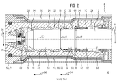
- the mated state is schematically shown in FIG 2 , which depicts a portion of the subsea connector unit 14 at a rear part 94 of the socket contact 88.
- the mating member 12 and the female part 76 each comprise a current carrying component 96 out of copper in the form of a conductive core in the case of the mating member 12 and the socket contact 88 in the case of the female part 76. Moreover, both comprise an insulating sleeve 70 out of, for example, insulative polyether ether ketone (PEEK), in circumferential direction 44 around the current carrying component 96. In other words, the sleeve 70 of the female part 74 encases the receiving chamber 16.
- PEEK insulative polyether ether ketone
- the socket contact 88 is embodied as a receiving chamber 16 comprising the receiving cavity 20 and a cavity wall 18 partially encasing the receiving cavity 20.
- the receiving cavity 20 is filled with the insulation medium 22 that travels the distribution path 24 caused by a mating force by the ingress of the mating member 12 in the receiving chamber 16 (see FIG 2 ).
- the cavity wall 18 of the receiving chamber 16 comprises a plurality of first radial apertures 26 or exit apertures 26 extending in a radial direction 98 of the receiving chamber 16 and a plurality of second radial apertures 32 or entry apertures 32 to provide the distribution path 24 for the insulation medium 22.
- an outer surface 30 of the cavity wall 18 comprises a plurality of axial channels 28 extending in parallel to an axis 100 of the connector unit 12. Further, the axial channels 28 are radially confined by an inner surface 72 of the sleeve 70.
- the axial channels 28, the exit apertures 26 and the entry apertures 32 are homogeneously distributed along an outer contour 38 or circumference of the cavity wall 18.
- the first radial apertures 26 are positioned at a bottom 46 of a first circumferential groove 40 and the second apertures 32 are positioned at a bottom 46 of a second circumferential groove 42.
- the first groove 40 and thus the first radial apertures 26 are located at a first axial end 36 of the channels 28 and the second groove 42 and thus the second radial apertures 32 are is located at a second axial end 36' positioned opposed from the first radial end 36.
- first radial aperture 26 and a second radial aperture 32 are located axially aligned towards each other.
- the first radial apertures 26 and the second radial apertures 32 are arranged in circumferential direction 44 offset from an axial extension 48 of a bottom 46 of the axial channels 28.
- a partitioning of the plurality of axial channels (28) is equal of a partitioning of the plurality of the first radial apertures 26 and of the second radial apertures 32.
- the cavity wall 18 comprises an axial end region 50 being located at a receiving opening 52 of the receiving cavity 20 and wherein the axial end region 50 comprises an annulus region 54 with an inner diameter d that is smaller than an inner diameter d of the receiving chamber 16. Furthermore, the inner diameter d of the annulus region 54 is selected in such a way that the mating member 12 is arranged with the clearance fit in the annulus region 54 (see FIG 2 ).
- the mating member 12 comprises a first section 58 embodied as a corrosion resistant tip, a second section 60 embodied as the current carrying component 96 and third axial section 62, comprises an insulating surface 68 that can be subjected to creepage and is thus a creepage surface.
- the dimensions of the parts of the mating member 12 and the receiving chamber 16 are selected in such a way that after the mate the first radial apertures 26 are located at an axial end 64 of the first section 58 of the mating member 12. Further, the axial channels 28 extend along the second and the third section 60, 62 of the mating member (12) and the second radial apertures 32 are located at an axial height where an axial end 66 of the third section 62 of the mating member 12 is positioned. Thus, the insulation medium 22 entering the space between the cavity wall 18 and the surface 68 through the enter apertures 32 travels along the surface 68.
- the surface 68 is a section 10 of the mating member 12 that can be conditioned or cleaned by making use of the insulation medium 22 flowing through the connector unit 12 during the mate by displacing the insulation medium 22 due to an ingress of the mating member 12 in the receiving chamber 16.
- the section 10 comprises the steps of:
- a size and/or shape (e.g. an angle) of the radial apertures 26, 32 and/or a size and/or shape (e.g. an varying or increasing depth in axial direction 34) of the axial channels 28 and/or a size and/or shape of the cavity wall of the receiving chamber 16, like the inner diameter d, especially at the annulus region 54, may be selected in dependency of at least one physical property of the insulation medium 22, like a flow rate, a density, a viscosity or a Rayolds number.
Priority Applications (4)
| Application Number | Priority Date | Filing Date | Title |
|---|---|---|---|
| EP14171160.6A EP2953211A1 (fr) | 2014-06-04 | 2014-06-04 | Procédé de conditionnement d'une section d'un élément d'accouplement |
| EP15720733.3A EP3152802B1 (fr) | 2014-06-04 | 2015-05-08 | Unité de connecteur comprennant un élément de connecteur et un élément d'accouplement et procédé de conditionnement d'une section de l'élément d'accouplement |
| US15/311,896 US10020612B2 (en) | 2014-06-04 | 2015-05-08 | Method for conditioning a section of a mating member |
| PCT/EP2015/060136 WO2015185324A1 (fr) | 2014-06-04 | 2015-05-08 | Procédé de conditionnement d'une section d'un élément d'accouplement |
Applications Claiming Priority (1)
| Application Number | Priority Date | Filing Date | Title |
|---|---|---|---|
| EP14171160.6A EP2953211A1 (fr) | 2014-06-04 | 2014-06-04 | Procédé de conditionnement d'une section d'un élément d'accouplement |
Publications (1)
| Publication Number | Publication Date |
|---|---|
| EP2953211A1 true EP2953211A1 (fr) | 2015-12-09 |
Family
ID=50897401
Family Applications (2)
| Application Number | Title | Priority Date | Filing Date |
|---|---|---|---|
| EP14171160.6A Withdrawn EP2953211A1 (fr) | 2014-06-04 | 2014-06-04 | Procédé de conditionnement d'une section d'un élément d'accouplement |
| EP15720733.3A Active EP3152802B1 (fr) | 2014-06-04 | 2015-05-08 | Unité de connecteur comprennant un élément de connecteur et un élément d'accouplement et procédé de conditionnement d'une section de l'élément d'accouplement |
Family Applications After (1)
| Application Number | Title | Priority Date | Filing Date |
|---|---|---|---|
| EP15720733.3A Active EP3152802B1 (fr) | 2014-06-04 | 2015-05-08 | Unité de connecteur comprennant un élément de connecteur et un élément d'accouplement et procédé de conditionnement d'une section de l'élément d'accouplement |
Country Status (3)
| Country | Link |
|---|---|
| US (1) | US10020612B2 (fr) |
| EP (2) | EP2953211A1 (fr) |
| WO (1) | WO2015185324A1 (fr) |
Cited By (1)
| Publication number | Priority date | Publication date | Assignee | Title |
|---|---|---|---|---|
| NO20160959A1 (en) * | 2016-06-03 | 2017-12-04 | Benestad Solutions As | High voltage subsea connection assembly |
Families Citing this family (2)
| Publication number | Priority date | Publication date | Assignee | Title |
|---|---|---|---|---|
| EP3168945B1 (fr) * | 2015-11-16 | 2019-10-30 | Siemens Aktiengesellschaft | Partie de connecteur d'un connecteur sous-marin et son procédé de connexion |
| EP3203588B1 (fr) * | 2016-02-02 | 2019-08-28 | Siemens Aktiengesellschaft | Procédé d'accouplement à sec d'une première partie de connecteur et d'une seconde partie de connecteur et ensemble connecteur |
Citations (3)
| Publication number | Priority date | Publication date | Assignee | Title |
|---|---|---|---|---|
| GB1562685A (en) * | 1976-08-20 | 1980-03-12 | British Petroleum Co | Electrical connector |
| GB2070348A (en) * | 1980-02-22 | 1981-09-03 | Inst Francais Du Petrole | Plug-in connector suitable for use in a liquid medium |
| US4373767A (en) * | 1980-09-22 | 1983-02-15 | Cairns James L | Underwater coaxial connector |
Family Cites Families (4)
| Publication number | Priority date | Publication date | Assignee | Title |
|---|---|---|---|---|
| US4142770A (en) | 1977-12-27 | 1979-03-06 | Exxon Production Research Company | Subsea electrical connector |
| US6776636B1 (en) * | 1999-11-05 | 2004-08-17 | Baker Hughes Incorporated | PBR with TEC bypass and wet disconnect/connect feature |
| GB2402558A (en) | 2003-06-05 | 2004-12-08 | Abb Vetco Gray Ltd | Electrical penetrator connector |
| US7097515B2 (en) * | 2005-01-19 | 2006-08-29 | Fmc Technologies, Inc. | Subsea electrical connector |
-
2014
- 2014-06-04 EP EP14171160.6A patent/EP2953211A1/fr not_active Withdrawn
-
2015
- 2015-05-08 US US15/311,896 patent/US10020612B2/en active Active
- 2015-05-08 EP EP15720733.3A patent/EP3152802B1/fr active Active
- 2015-05-08 WO PCT/EP2015/060136 patent/WO2015185324A1/fr active Application Filing
Patent Citations (3)
| Publication number | Priority date | Publication date | Assignee | Title |
|---|---|---|---|---|
| GB1562685A (en) * | 1976-08-20 | 1980-03-12 | British Petroleum Co | Electrical connector |
| GB2070348A (en) * | 1980-02-22 | 1981-09-03 | Inst Francais Du Petrole | Plug-in connector suitable for use in a liquid medium |
| US4373767A (en) * | 1980-09-22 | 1983-02-15 | Cairns James L | Underwater coaxial connector |
Cited By (6)
| Publication number | Priority date | Publication date | Assignee | Title |
|---|---|---|---|---|
| NO20160959A1 (en) * | 2016-06-03 | 2017-12-04 | Benestad Solutions As | High voltage subsea connection assembly |
| WO2017207766A1 (fr) * | 2016-06-03 | 2017-12-07 | Benestad Solutions As | Ensemble de connexion sous-marin à haute tension |
| NO342320B1 (en) * | 2016-06-03 | 2018-05-07 | Benestad Solutions As | High voltage subsea connection assembly |
| CN109196730A (zh) * | 2016-06-03 | 2019-01-11 | 本尼斯泰德解决方案股份公司 | 高电压水下连接组件 |
| GB2576586A (en) * | 2016-06-03 | 2020-02-26 | Benestad Solutions As | High voltage subsea connection assembly |
| US10833449B2 (en) | 2016-06-03 | 2020-11-10 | Benestad Solutions As | High voltage subsea connection assembly |
Also Published As
| Publication number | Publication date |
|---|---|
| EP3152802B1 (fr) | 2020-04-01 |
| US20170093083A1 (en) | 2017-03-30 |
| WO2015185324A1 (fr) | 2015-12-10 |
| EP3152802A1 (fr) | 2017-04-12 |
| US10020612B2 (en) | 2018-07-10 |
Similar Documents
| Publication | Publication Date | Title |
|---|---|---|
| CA2620273C (fr) | Connecteur electrique a haute tension pouvant etre apparie en milieu humide | |
| US10975653B2 (en) | Disconnectable pressure-preserving electrical connector and method of installation | |
| EP2792030B1 (fr) | Connection electrique sous marine | |
| EP2457292B1 (fr) | Connecteur étanche | |
| US7575458B2 (en) | Hi-dielectric debris seal for a pothead interface | |
| EP2771539B1 (fr) | Terminaison de connecteur a equilibrage de pression | |
| US7325596B2 (en) | Pothead assembly | |
| EP3152802B1 (fr) | Unité de connecteur comprennant un élément de connecteur et un élément d'accouplement et procédé de conditionnement d'une section de l'élément d'accouplement | |
| NO20170640A1 (en) | Crushed seal arrangement for motor electrical connection of submersible well pump | |
| EP3438408A1 (fr) | Ensemble connecteur | |
| CN115173136A (zh) | 海底连接器 | |
| BR112013001532B1 (pt) | conjunto de bomba de poço submersível com selo de detritos dielétricos de mitigação de pressão para interface de conector elétrico | |
| EP2665138A2 (fr) | Connexion électrique sous-marine et ensembles de terminaison | |
| BR102014023902A2 (pt) | método para fabricação de parte condutora e parte condutora de uma unidade de conector | |
| EP2665135A1 (fr) | Connexion électrique sous-marine et ensembles de terminaison | |
| EP2665136A1 (fr) | Connexion électrique sous-marine et ensembles de terminaison | |
| CA2601553C (fr) | Joint d'etancheite a dielectrique eleve a l'epreuve des debris pour l'interface des boites d'extremite | |
| EP2665137A1 (fr) | Connexion électrique sous-marine et ensembles de terminaison |
Legal Events
| Date | Code | Title | Description |
|---|---|---|---|
| PUAI | Public reference made under article 153(3) epc to a published international application that has entered the european phase |
Free format text: ORIGINAL CODE: 0009012 |
|
| AK | Designated contracting states |
Kind code of ref document: A1 Designated state(s): AL AT BE BG CH CY CZ DE DK EE ES FI FR GB GR HR HU IE IS IT LI LT LU LV MC MK MT NL NO PL PT RO RS SE SI SK SM TR |
|
| AX | Request for extension of the european patent |
Extension state: BA ME |
|
| STAA | Information on the status of an ep patent application or granted ep patent |
Free format text: STATUS: THE APPLICATION IS DEEMED TO BE WITHDRAWN |
|
| 18D | Application deemed to be withdrawn |
Effective date: 20160610 |