EP2953192B1 - Negative active material for rechargeable lithium battery, and rechargeable lithium battery including same - Google Patents
Negative active material for rechargeable lithium battery, and rechargeable lithium battery including same Download PDFInfo
- Publication number
- EP2953192B1 EP2953192B1 EP15169970.9A EP15169970A EP2953192B1 EP 2953192 B1 EP2953192 B1 EP 2953192B1 EP 15169970 A EP15169970 A EP 15169970A EP 2953192 B1 EP2953192 B1 EP 2953192B1
- Authority
- EP
- European Patent Office
- Prior art keywords
- carbon
- active material
- lithium battery
- rechargeable lithium
- negative active
- Prior art date
- Legal status (The legal status is an assumption and is not a legal conclusion. Google has not performed a legal analysis and makes no representation as to the accuracy of the status listed.)
- Active
Links
Images



Classifications
-
- H—ELECTRICITY
- H01—ELECTRIC ELEMENTS
- H01M—PROCESSES OR MEANS, e.g. BATTERIES, FOR THE DIRECT CONVERSION OF CHEMICAL ENERGY INTO ELECTRICAL ENERGY
- H01M4/00—Electrodes
- H01M4/02—Electrodes composed of, or comprising, active material
- H01M4/36—Selection of substances as active materials, active masses, active liquids
- H01M4/362—Composites
- H01M4/366—Composites as layered products
-
- C—CHEMISTRY; METALLURGY
- C01—INORGANIC CHEMISTRY
- C01B—NON-METALLIC ELEMENTS; COMPOUNDS THEREOF; METALLOIDS OR COMPOUNDS THEREOF NOT COVERED BY SUBCLASS C01C
- C01B32/00—Carbon; Compounds thereof
- C01B32/05—Preparation or purification of carbon not covered by groups C01B32/15, C01B32/20, C01B32/25, C01B32/30
-
- H—ELECTRICITY
- H01—ELECTRIC ELEMENTS
- H01M—PROCESSES OR MEANS, e.g. BATTERIES, FOR THE DIRECT CONVERSION OF CHEMICAL ENERGY INTO ELECTRICAL ENERGY
- H01M10/00—Secondary cells; Manufacture thereof
- H01M10/05—Accumulators with non-aqueous electrolyte
- H01M10/052—Li-accumulators
-
- H—ELECTRICITY
- H01—ELECTRIC ELEMENTS
- H01M—PROCESSES OR MEANS, e.g. BATTERIES, FOR THE DIRECT CONVERSION OF CHEMICAL ENERGY INTO ELECTRICAL ENERGY
- H01M4/00—Electrodes
- H01M4/02—Electrodes composed of, or comprising, active material
- H01M4/04—Processes of manufacture in general
- H01M4/0471—Processes of manufacture in general involving thermal treatment, e.g. firing, sintering, backing particulate active material, thermal decomposition, pyrolysis
-
- H—ELECTRICITY
- H01—ELECTRIC ELEMENTS
- H01M—PROCESSES OR MEANS, e.g. BATTERIES, FOR THE DIRECT CONVERSION OF CHEMICAL ENERGY INTO ELECTRICAL ENERGY
- H01M4/00—Electrodes
- H01M4/02—Electrodes composed of, or comprising, active material
- H01M4/36—Selection of substances as active materials, active masses, active liquids
- H01M4/58—Selection of substances as active materials, active masses, active liquids of inorganic compounds other than oxides or hydroxides, e.g. sulfides, selenides, tellurides, halogenides or LiCoFy; of polyanionic structures, e.g. phosphates, silicates or borates
- H01M4/583—Carbonaceous material, e.g. graphite-intercalation compounds or CFx
-
- H—ELECTRICITY
- H01—ELECTRIC ELEMENTS
- H01M—PROCESSES OR MEANS, e.g. BATTERIES, FOR THE DIRECT CONVERSION OF CHEMICAL ENERGY INTO ELECTRICAL ENERGY
- H01M4/00—Electrodes
- H01M4/02—Electrodes composed of, or comprising, active material
- H01M4/36—Selection of substances as active materials, active masses, active liquids
- H01M4/58—Selection of substances as active materials, active masses, active liquids of inorganic compounds other than oxides or hydroxides, e.g. sulfides, selenides, tellurides, halogenides or LiCoFy; of polyanionic structures, e.g. phosphates, silicates or borates
- H01M4/583—Carbonaceous material, e.g. graphite-intercalation compounds or CFx
- H01M4/587—Carbonaceous material, e.g. graphite-intercalation compounds or CFx for inserting or intercalating light metals
-
- C—CHEMISTRY; METALLURGY
- C01—INORGANIC CHEMISTRY
- C01P—INDEXING SCHEME RELATING TO STRUCTURAL AND PHYSICAL ASPECTS OF SOLID INORGANIC COMPOUNDS
- C01P2002/00—Crystal-structural characteristics
- C01P2002/80—Crystal-structural characteristics defined by measured data other than those specified in group C01P2002/70
- C01P2002/82—Crystal-structural characteristics defined by measured data other than those specified in group C01P2002/70 by IR- or Raman-data
-
- H—ELECTRICITY
- H01—ELECTRIC ELEMENTS
- H01M—PROCESSES OR MEANS, e.g. BATTERIES, FOR THE DIRECT CONVERSION OF CHEMICAL ENERGY INTO ELECTRICAL ENERGY
- H01M4/00—Electrodes
- H01M4/02—Electrodes composed of, or comprising, active material
- H01M2004/021—Physical characteristics, e.g. porosity, surface area
-
- H—ELECTRICITY
- H01—ELECTRIC ELEMENTS
- H01M—PROCESSES OR MEANS, e.g. BATTERIES, FOR THE DIRECT CONVERSION OF CHEMICAL ENERGY INTO ELECTRICAL ENERGY
- H01M4/00—Electrodes
- H01M4/02—Electrodes composed of, or comprising, active material
- H01M2004/026—Electrodes composed of, or comprising, active material characterised by the polarity
- H01M2004/027—Negative electrodes
-
- H—ELECTRICITY
- H01—ELECTRIC ELEMENTS
- H01M—PROCESSES OR MEANS, e.g. BATTERIES, FOR THE DIRECT CONVERSION OF CHEMICAL ENERGY INTO ELECTRICAL ENERGY
- H01M4/00—Electrodes
- H01M4/02—Electrodes composed of, or comprising, active material
- H01M4/13—Electrodes for accumulators with non-aqueous electrolyte, e.g. for lithium-accumulators; Processes of manufacture thereof
- H01M4/133—Electrodes based on carbonaceous material, e.g. graphite-intercalation compounds or CFx
-
- Y—GENERAL TAGGING OF NEW TECHNOLOGICAL DEVELOPMENTS; GENERAL TAGGING OF CROSS-SECTIONAL TECHNOLOGIES SPANNING OVER SEVERAL SECTIONS OF THE IPC; TECHNICAL SUBJECTS COVERED BY FORMER USPC CROSS-REFERENCE ART COLLECTIONS [XRACs] AND DIGESTS
- Y02—TECHNOLOGIES OR APPLICATIONS FOR MITIGATION OR ADAPTATION AGAINST CLIMATE CHANGE
- Y02E—REDUCTION OF GREENHOUSE GAS [GHG] EMISSIONS, RELATED TO ENERGY GENERATION, TRANSMISSION OR DISTRIBUTION
- Y02E60/00—Enabling technologies; Technologies with a potential or indirect contribution to GHG emissions mitigation
- Y02E60/10—Energy storage using batteries
Definitions
- Embodiments are directed to negative active material for a rechargeable lithium battery and a rechargeable lithium battery including the same.
- a rechargeable lithium battery has been widely applied as a power source for electric vehicles, electric power storage apparatuses, or the like, as well as for a small portable electronic device.
- a customized electrode active material is desirable.
- US 2005/058904 relates to a secondary battery.
- Tsumara T. et al., "Surface modification of natural graphite particles for lithium ion batteries", Solid State Ionics, 2000, vol. 135, no. 1-4, pages 209-212 , relates to the surface modification of natural graphite particles by means of carbon coating and polyethyleneoxide grafting.
- JP 2001273894 relates to a manufacturing method of a negative active material for a lithium secondary battery.
- JP 2013098089 relates to an evaluation method for an anode active material.
- a rechargeable lithium battery as set out in claim 10.
- a negative active material for a rechargeable lithium battery includes a composite carbon particle including a core particle including crystalline-based carbon and a coating layer positioned on the surface of the core particle and including amorphous carbon.
- the peak intensity (I 1620 ) at 1620 cm- 1 is in a range of 0.01 to 0.1
- the peak intensity (I 1360 ) at 1360 cm- 1 is in a range of 0.05 to 0.5
- the peak intensity (I 1580 ) at 1580 cm- 1 is in a range of 0.1 to 0.8.
- the peak intensity (I 1360 ) at 1360 cm- 1 , the peak intensity (I 1580 ) at 1580 cm- 1 , and the peak intensity (I 1620 ) at 1620 cm- 1 may be respectively represented as I D , I G and I D' .
- the Raman spectrum is measured by using an Ar laser as a target source.
- the Ar laser has a wave length of about 514nm.
- the Raman Spectrum may be measured by using a NRS 1000 Raman Spectrometer available from Jasco Inc.
- a composite carbon particle having the I D , I G and I D ' values within the ranges may have relatively small interface resistance. This result may indicate a satisfactory amalgamation state between the core particle formed of crystalline-based carbon and the coating layer formed of amorphous carbon.
- the I D , I G and I D values may just satisfy the range, but combinations thereof have no particular limit.
- a ratio of the peak intensity (I 1360 ) at 1360 cm- 1 to the peak intensity (I 1620 ) at 1620 cm-1 (I 1360 /I 1620 , that is, I D /I D ') in the Raman spectrum of the composite carbon particle is 2 to 5.
- boundary-shaped defects may be more prevalent than vacancy-shaped defects on the interface between the crystalline-based carbon core and the amorphous carbon coating layer.
- a defect on the interface of a composite particle may be classified into a boundary-shaped defect and a vacancy-shaped defect, wherein the boundary-shaped defect indicates a linearly-dislocated defect, while the vacancy-shaped defect indicates a defect positioned like a dot.
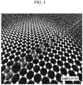
- FIG. 1 is a drawing illustrating a boundary-shaped defect
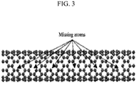
- FIGS. 2 and 3 are drawings illustrating vacancy-shaped defects.
- the vacancy-shaped defect may be generated by missing atoms unlike the boundary-shaped defect.
- boundary-shaped defect may have relatively more defect sites than the vacancy-shaped defect and thus, may secure more paths for lithium intercalation.
- the composite carbon particle may have a dualistic structure including a crystalline-based carbon as a core particle and amorphous carbon on the surface of the core particle. Excellent amalgamation between the crystalline-based carbon and amorphous carbon may be accomplished, and lithium ions may be substantially transported as if there were no interface between the core and the coating layer.
- the composite carbon particle may exhibit characteristics similar to those of socalled pseudo-crystallized carbon.
- the amorphous carbon may be included in an amount of about 0.1 wt% to about 50 wt% based on the total weight or amount of the composite carbon particle. Within the range, the amorphous carbon may be, for example, included in an amount of about 1 wt% to 30 wt%, 5 wt% to 30 wt%, or 5 wt% to 25 wt%. When the amorphous carbon is included within the range, high power characteristics of a rechargeable lithium battery may be secured.
- the Raman peak of the composite carbon particle according to one embodiment is illustrated again.
- a ratio (I 1620 /I 1580 , that is to say, I D '/I G ) of the peak intensity (I 1620 ) at 1620 cm- 1 relative to the peak intensity (I 1580 ) at 1580 cm- 1 is 0.01 to 0.5, and preferably 0.01 to 0.2, or 0.05 to 0.13 in a Raman spectrum of the composite carbon particle.
- a ratio (I 1620 /I 1580 , that is to say, I D '/I G ) of the peak intensity (I 1620 ) at 1620 cm- 1 relative to the peak intensity (I 1580 ) at 1580 cm- 1 in a Raman spectrum of the composite carbon particle may have a substantially constant value regardless of the content of the amorphous carbon particle.
- the substantially constant value is within an error range of ⁇ 0.025.
- the constant I D '/I G value regardless of the content of the amorphous carbon particle may obtained by a small structural defect on the interface between the crystalline-based carbon core and the amorphous carbon coating layer.
- the average particle diameter (D 50 ) of the core particle may be, for example about 3 ⁇ m to about 50 ⁇ m.
- the term "average particle diameter (D 50 )" indicates a particle diameter corresponding to 50 volume% of a cumulative volume in a particle distribution.
- the thickness of the coating layer may be about 0.001 ⁇ m to about 30 ⁇ m, for example about 0.01 ⁇ m to about 20 ⁇ m, or about 0.1 ⁇ m to about 15 ⁇ m. When the thickness of the coating layer is within the range, initial efficiency characteristics, highrate charge and discharge characteristics and cycle-life characteristics may be improved.
- the average particle diameter (D 50 ) of the composite carbon particle may be, for example about 7 ⁇ m to about 80 ⁇ m.
- the crystalline-based carbon included in the core particle may include, for example, natural graphite, artificial graphite or a combination thereof.
- the amorphous carbon included in the coating layer may include, for example, soft carbon, hard carbon, or a combination thereof.
- the soft carbon may be obtained from coal pitch, petroleum pitch, polyvinylchloride, mesophase pitch, tar, low molecular weight heavy oil, or a combination thereof.
- the hard carbon may be obtained from a polyvinyl alcohol resin, a furfuryl alcohol resin, triton, citric acid, stearic acid, sucrose, polyvinylidene fluoride, carboxylmethyl cellulose, hydroxypropyl cellulose, regenerated cellulose, polyvinylpyrrolidone, polyethylene, polypropylene, an ethylene-propylene-diene monomer (EPDM), polyacrylic acid, sodium polyacrylate, polyacrylonitrile, glucose, gelatin, a saccharide, a phenolic resin, a naphthalene resin, a polyamide resin, a furan resin, a polyimide resin, cellulose resin, a styrene resin, an epoxy resin and vinyl chloride resin, or a combination thereof, as examples.
- the rechargeable lithium battery including the negative active material according to another embodiment is provided.
- the rechargeable lithium battery is illustrated referring to FIG. 4 , which shows one example of the rechargeable lithium battery.
- the rechargeable battery may have any suitable shape such as a prismatic shape, a coin-type shape, a pouch shape, or the like, as well as a cylinder shape.
- FIG. 4 is a schematic view showing a rechargeable lithium battery according to one embodiment.
- a rechargeable lithium battery 100 may include an electrode assembly including a positive electrode 114, a negative electrode 112 facing the positive electrode 114, a separator 113 interposed between the negative electrode 112 and the positive electrode 114, an electrolyte (not shown) impregnating the separator 113, a battery case 120, and a sealing member 140 sealing the battery case 120.
- the electrode assembly may be impregnated in an electrolyte.
- the negative electrode 112 may include a current collector and a negative active material layer formed on the current collector.
- the current collector may be a copper foil.
- the negative active material layer may include a negative active material, a binder, and optionally, a conductive material.
- the negative active material may be the same as described above.
- the binder may improve binding properties of negative active material particles with one another and with a current collector.
- the binder may be an organic binder.
- the organic binder may be polyvinylidene fluoride, polyimide, polyamideimide, polyamide, aramid, polyacrylate, polyetheretherketone, polyetherimide, polyethersulfone, polysulfone, polyphenylenesulfide, polytetrafluoroethylene, or a combination thereof.
- the conductive material may improve conductivity of an electrode.
- Any suitable electrically conductive material that does not cause a chemical change may be used as the conductive material. Examples thereof include a carbon-based material such as natural graphite, artificial graphite, carbon black, acetylene black, ketjen black, a carbon fiber, or the like; a metal-based material such as a metal powder or a metal fiber, or the like of copper, nickel, aluminum, silver, and the like; a conductive polymer such as a polyphenylene derivative or the like; or a mixture thereof.
- the negative active material may be included in an amount of about 90 wt% to 98 wt%, the binder may be included in an amount of about 1 wt% to about 5 wt% and the conductive material may be included in an amount of about 1 wt% to about 5 wt%.
- the negative electrode may be manufactured by mixing the negative active material, the conductive material, and the organic binder in water to prepare a negative active material layer composition, and coating the negative active material layer composition onto the current collector.
- the positive electrode 114 may include a current collector and a positive active material layer formed on the current collector.
- the positive active material layer may include a positive active material, a binder, and optionally, a conductive material.
- the current collector may include Al (aluminum), for example.
- the positive active material may include lithiated intercalation compounds that reversibly intercalate and deintercalate lithium ions.
- the positive active material may be a lithium-containing compound of a lithium-containing oxide, a lithium-containing phosphate salt, a lithium-containing silicate, or a combination thereof.
- the lithium-containing oxide, the lithium-containing phosphate salt and the lithium-containing silicate may be respectively an oxide, a phosphate salt and a silicate that include lithium and a metal.
- Examples of the metal may be Co, Ni, Mn, Fe, Cu, V, Si, Al, Sn, Pb, Sn, Ti, Sr, Mg, Ca, or the like.
- lithium-containing oxide examples include lithium cobalt oxide, lithium nickel oxide, lithium manganese oxide, lithium nickel cobalt manganese oxide, lithium nickel cobalt aluminum oxide, or the like.
- lithium-containing phosphate salt examples include a lithium iron phosphate salt, a lithium manganese phosphate, a lithium iron molybdenum phosphate salt, or the like.
- the positive active material may include activated carbon other than the lithium-containing compound.
- activated carbon other than the lithium-containing compound.
- the activated carbon may be a porous carbon material and thus, may have strong ion adsorption due to a large surface area and a fast chemical reaction.
- the activated carbon may be included in an amount of about 1 wt% to about 40 wt%, or, for example, about 1 wt% to about 15 wt%, or, for example, about 3 wt% to about 5 wt% based on the total amount of the lithium-containing compound and the activated carbon.
- the activated carbon is used within the range, high energy density and high power characteristics may be simultaneously secured.
- the binder may improve binding properties of positive active material particles with one another and with a current collector.
- Specific examples may include polyvinyl alcohol, carboxylmethyl cellulose, hydroxypropyl cellulose, diacetyl cellulose, polyvinylchloride, carboxylated polyvinylchloride, polyvinylfluoride, an ethylene oxidecontaining polymer, polyvinylpyrrolidone, polyurethane, polytetrafluoroethylene, polyvinylidene fluoride, polyethylene, polypropylene, a styrene-butadiene rubber, an acrylated styrene-butadiene rubber, an epoxy resin, nylon, or the like.
- the conductive material improves conductivity of an electrode.
- any suitable electrically conductive material that does not cause a chemical change may be used as the conductive material included in the positive electrode. Examples thereof may include one or more of natural graphite, artificial graphite, carbon black, acetylene black, ketjen black, a carbon fiber, a metal powder, a metal fiber, or the like of copper, nickel, aluminum, silver, or the like, or a conductive material such as a polyphenylene derivative or the like.
- the positive active material may be included in an amount of about 90 wt% to 98 wt%, the binder may be included in an amount of about 1 wt% to about 5 wt% and the conductive material may be included in an amount of about 1 wt% to about 5 wt%.
- the positive electrode may be manufactured by combining an active material, a conductive material, and a binder in a solvent to prepare an active material composition, and coating the composition onto a current collector.
- the solvent may include N-methylpyrrolidone and the like, but is not limited thereto in embodiments of the invention.
- the electrolyte solution may include a non-aqueous organic solvent and a lithium salt.
- the non-aqueous organic solvent may serve as a medium for transmitting ions taking part in the electrochemical reaction of a battery.
- the non-aqueous organic solvent may be selected from a carbonate-based, ester-based, ether-based, ketone-based, alcohol-based, and aprotic solvent.
- the carbonate based solvent may be, for example, dimethyl carbonate (DMC), diethyl carbonate (DEC), dipropyl carbonate (DPC), methylpropyl carbonate (MPC), ethylpropyl carbonate (EPC), methylethyl carbonate (MEC), ethylene carbonate (EC), propylene carbonate (PC), butylene carbonate (BC), or the like.
- DMC dimethyl carbonate
- DEC diethyl carbonate
- DPC dipropyl carbonate
- MPC methylpropyl carbonate
- EPC ethylpropyl carbonate
- MEC methylethyl carbonate
- EC ethylene carbonate
- PC propylene carbonate
- BC butylene carbonate
- an organic solvent having a high dielectric constant and a low viscosity may be provided.
- the cyclic carbonate and the chain carbonate may be mixed together in a volume ratio ranging from about 1:1 to 1:9.
- ester-based solvent may be, for example, methylacetate, ethylacetate, n-propylacetate, dimethylacetate, methylpropionate, ethylpropionate, ⁇ -butyrolactone, decanolide, valerolactone, mevalonolactone, caprolactone, or the like.
- the ether-based solvent may be, for example dibutylether, tetraglyme, diglyme, dimethoxyethane, 2-methyltetrahydrofuran, tetrahydrofuran, or the like, and the ketone-based solvent may be cyclohexanone, or the like.
- the alcohol-based solvent may be ethanol, isopropyl alcohol, or the like.
- the non-aqueous organic solvent may be used singularly or in a mixture, and when the organic solvent is used in a mixture, the mixture ratio may be controlled in accordance with a desirable battery performance.
- the electrolyte may further include an overcharge inhibitor additive such as ethylene-based carbonate, pyrocarbonate, or the like.
- an overcharge inhibitor additive such as ethylene-based carbonate, pyrocarbonate, or the like.
- the lithium salt may be dissolved in an organic solvent, may supply lithium ions in a battery, may basically operate the rechargeable lithium battery, and may improve lithium ion transportation between positive and negative electrodes therein.
- lithium salt examples include LiPF 6 , LiBF 4 , LiSbF 6 , LiAsF 6 , LiN(SO 3 C 2 F 5 ) 2 , LiC 4 F 9 SO 3 , LiClO 4 , LiAlO 2 , LiAlCl 4 , LiN(C x F 2x+1 SO 2 )(C y F 2y+1 SO 2 ), wherein, x and y are natural numbers, e.g. an integer of 1 to 20, LiCl, LiI, LiB(C 2 O 4 ) 2 (lithium bis(oxalato) borate, LiBOB), or a combination thereof.
- the lithium salt may be used in a concentration ranging from about 0.1 M to about 2.0 M.
- an electrolyte may have excellent performance and lithium ion mobility due to optimal electrolyte conductivity and viscosity.
- the separator 113 separates the negative electrode 112 from the positive electrode 114 and provides a transporting passage for lithium ion.
- the separator 113 may include any suitable material for use in a lithium battery.
- the separator may have a low resistance to ion transportation and an excellent impregnation for an electrolyte.
- the separator 113 may be selected from glass fiber, polyester, polyethylene, polypropylene, polytetrafluoroethylene (PTFE), or a combination thereof.
- the separator 113 may have a form of a non-woven fabric or a woven fabric.
- a polyolefinbased polymer separator such as polyethylene, polypropylene or the like may be used.
- a coated separator including a ceramic component or a polymer material may be used.
- the separator may have a monolayered or multi-layered structure.
- Soft carbon was coated on the core of an artificial graphite (average particle diameter (D 50 ): 10 ⁇ m) by a chemical vapor deposition method in which the artificial graphite was put into a chamber and the temperature of the chamber was increased from 300°C to 800°C, while Ar gas which was bubbled in toluene was flowed at a flux of 100L/h to form single coating layer with a thickness of 13nm.
- the thickness of the coating layer was mechanically controlled to include the soft carbon in an amount of 5 wt% based on the total weight of the entire carbon particles.
- the coated graphite particles were heat-treated at 1,100 °C for 5 hours, obtaining composite carbon particles.
- Composite carbon particles were obtained according to the same method as Example 1 except for including the soft carbon in an amount of 15 wt% based on the total weight of the entire carbon particles.
- Composite carbon particles were obtained according to the same method as Example 1 except for including the soft carbon in an amount of 25 wt% based on the total weight of the entire carbon particles.
- Artificial graphite as a core was added to a colloid pitch solution in which soft carbon particles were dispersed.
- a thin coating layer including sulphur component was formed on the core surface of artificial graphite in an atomization method.
- the sulfur components were derived from sulfur impurities included in the colloid pitch solution.
- the obtained graphite particles were heated by increasing a temperature by 2 °C/min up to 500 °C under a room temperature nitrogen atmosphere.
- the resulting graphite particles were maintained at 500 °C for about 3 hours to form the coating layer on the surface of the graphite.
- a thin film structure was formed by removing nitrogen therefrom and injecting air in a small amount thereinto.
- the thickness of the coating layer was adjusted to include the soft carbon in an amount of 5 wt% based on the total weight of the entire carbon particles.
- Composite carbon particle were obtained according to the same method as Example 4 except for including the soft carbon in an amount of 15 wt% based on the total weight of the entire carbon particle.
- Composite carbon particle were obtained according to the same method as Example 4 except for including the soft carbon in an amount of 25 wt% based on the total weight of the entire carbon particle.
- Graphite particles available from Aldrich were used.
- FIGS. 5 and 6 respectively show 2,000x and 5,000x SEM images of the composite carbon particle according to Example 1.
- the composite carbon particles of Example 1 had an average particle diameter (D 50 ) of about 10 to 13 ⁇ m.
- the XRD analysis results of the composite carbon particles of Examples 1 to 3 and the graphite particles of Comparative Example 1 (as well as composite carbon particles formed according to Example 1 and including soft carbon in the amounts of 10% and 20%) are provided in FIG. 7 .
- the result of Comparative Example 1 showed a 002 peak, which is a main peak of graphite, and as the coating amount of the soft carbon increased, a 101 peak became wider.
- Table 1 Peak intensity D' band D band G band Ratio of D'/G band Ratio of D/G band Ratio of D/D' band
- Example 1 S.C. 5 wt.% coating 0.031 0.098 0.235 0.131 0.417 3.2
- Example 2 S.C. 15 wt.% coating 0.025 0.105 0.184 0.134 0.571 4.2
- Example 3 S.C. 25 wt.% coating 0.053 0.244 0.409 0.129 0.597 4.6
- Example 4 S.C. 5 wt.% coating 0.035 0.100 0.232 0.151 0.431 2.9
- Example 5 S.C. 15 wt.% coating 0.022 0.104 0.180 0.122 0.578 4.7
- Example 6 S.C. 25 wt.% coating 0.052 0.240 0.407 0.128 0.590 4.6
- peak intensity at D', D and G bands respectively indicates peak intensity (I 1620 ) at 1620 cm- 1 , peak intensity (I 1360 ) at 1360 cm- 1 and peak intensity (I 1580 ) at 1580 cm- 1 .
- the D'/G peak intensity was about 0.13 to about 0.15 regardless of the coating amount of the soft carbon. Without being bound to any particular theory, is believed that the reason the D'/G peak intensity was about 0.13 regardless of the coating amount of the soft carbon in the composite carbon particles of Examples 1 to 6 was that the peak intensity at the D' band indicates that a structural defect on the surface of a core was constantly maintained regardless of the coating amount, indicating that the core and the coating layer were highly fused.
- Carbon-based materials are generally classified into crystalline-based graphite and amorphous carbon.
- the crystalline-based graphite is generally used as a power source for a small portable electronic device
- the amorphous carbon is generally used as a negative active material for a rechargeable lithium battery as a power source for a hybrid vehicle (HEV) requiring high power characteristics.
- HEV hybrid vehicle
- Embodiments provide a negative active material for a rechargeable lithium battery having high power characteristics by improving an interface amalgamation degree between a crystalline-based carbon core and an amorphous carbon coating layer, i.e., reducing an interface resistance, and thus, decreasing transport resistance of lithium ions.
- the composite carbon particle for a negative active material including a core particle of a crystalline-based carbon component and a coating layer of an amorphous carbon component according to embodiments, high power characteristics of a rechargeable lithium battery may be secured by achieving a high amalgamation degree on the interface between the core particle and the coating layer such that lithium may be smoothly intercalated and deintercalated.
- Another embodiment provides the negative electrode including a negative active material.
- Another embodiment provides a rechargeable lithium battery including the negative electrode.
Landscapes
- Chemical & Material Sciences (AREA)
- Chemical Kinetics & Catalysis (AREA)
- Electrochemistry (AREA)
- General Chemical & Material Sciences (AREA)
- Inorganic Chemistry (AREA)
- Composite Materials (AREA)
- Engineering & Computer Science (AREA)
- Manufacturing & Machinery (AREA)
- Organic Chemistry (AREA)
- Battery Electrode And Active Subsutance (AREA)
- Secondary Cells (AREA)
Description
- Embodiments are directed to negative active material for a rechargeable lithium battery and a rechargeable lithium battery including the same.
- Recently, a rechargeable lithium battery has been widely applied as a power source for electric vehicles, electric power storage apparatuses, or the like, as well as for a small portable electronic device. For the various uses, a customized electrode active material is desirable.
-
US 2005/058904 relates to a secondary battery. - Tsumara, T. et al., "Surface modification of natural graphite particles for lithium ion batteries", Solid State Ionics, 2000, vol. 135, no. 1-4, pages 209-212, relates to the surface modification of natural graphite particles by means of carbon coating and polyethyleneoxide grafting.
- Wang, Y. et al., "Raman Spectroscopy of Carbon Materials: Structural Basis of Observed Spectra", Chemistry of Materials, 1990, vol. 2, , relates to first and second order Raman spectral features of carbon materials.
-
JP 2001273894 -
JP 2013098089 - Nanda, J. et al., "In situ Raman microscopy during discharge of a high capacity silicon-carbon composite Li-ion battery negative electrode", Electrochemistry Communications, 2009, vol. 11, issue 11, pages 235-237, relates to an in situ Raman microscopy study performed in order to characterize the surface of a Si/C composite anode.
- Datta, M. K. and Kumta, P. N., "Silicon and carbon based composite anodes for lithium ion batteries", Journal of Power Sources,vol. 158, , relates to composites comprising silicon, graphite and polyacrylonitrile-based disordered carbon.
- According to an aspect of the invention, there is provided a negative active material as set out in
claim 1. Preferred features are set out inclaims 2 to 8. - According to an aspect of the invention, there is provided a negative electrode as set out in claim 9.
- According to an aspect of the invention, there is provided a rechargeable lithium battery as set out in
claim 10. - Features will become apparent to those of skill in the art by describing in detail exemplary embodiments with reference to the attached drawings in which:
-
FIG. 1 is a drawing illustrating the concept of a boundary-shaped defect formed on the interface between crystalline-based carbon and amorphous carbon, -
FIGS. 2 and3 are drawings illustrating the concept of a vacancy-shaped defect on the interface between crystalline-based carbon and amorphous carbon, -
FIG. 4 illustrates a schematic view showing a rechargeable lithium battery according to one embodiment, -
FIGS. 5 and6 illustrate drawings respectively showing 2,000x and 5,000x SEM images of the composite carbon particle of Example 1, and -
FIG. 7 illustrates a graph showing XRD analysis results of the composite carbon particles according to Examples 1 to 3 and graphite particle according to Comparative Example 1. - Example embodiments will now be described more fully hereinafter with reference to the accompanying drawings; however, they may be embodied in different forms and should not be construed as limited to the embodiments set forth herein. Rather, these embodiments are provided so that this disclosure will be thorough and complete, and will fully convey exemplary implementations to those skilled in the art. In the drawing figures, the dimensions of layers and regions may be exaggerated for clarity of illustration.
- A negative active material for a rechargeable lithium battery according to one embodiment includes a composite carbon particle including a core particle including crystalline-based carbon and a coating layer positioned on the surface of the core particle and including amorphous carbon.
- When the Raman spectrum of the composite carbon particle is measured, the peak intensity (I1620) at 1620 cm-1 is in a range of 0.01 to 0.1, the peak intensity (I1360) at 1360 cm-1 is in a range of 0.05 to 0.5, and the peak intensity (I1580) at 1580 cm-1 is in a range of 0.1 to 0.8. The peak intensity (I1360) at 1360 cm-1, the peak intensity (I1580) at 1580 cm-1, and the peak intensity (I1620) at 1620 cm-1 may be respectively represented as ID, IG and ID'. The Raman spectrum is measured by using an Ar laser as a target source. The Ar laser has a wave length of about 514nm. Furthermore, the Raman Spectrum may be measured by using a NRS 1000 Raman Spectrometer available from Jasco Inc.
- A composite carbon particle having the ID, IG and ID' values within the ranges may have relatively small interface resistance. This result may indicate a satisfactory amalgamation state between the core particle formed of crystalline-based carbon and the coating layer formed of amorphous carbon. Herein, the ID, IG and ID values may just satisfy the range, but combinations thereof have no particular limit.
- A ratio of the peak intensity (I1360) at 1360 cm-1 to the peak intensity (I1620) at 1620 cm-1 (I1360/I1620, that is, ID/ID') in the Raman spectrum of the composite carbon particle is 2 to 5.
- When the ID/ID' is within the range, boundary-shaped defects may be more prevalent than vacancy-shaped defects on the interface between the crystalline-based carbon core and the amorphous carbon coating layer.
- In general, a defect on the interface of a composite particle may be classified into a boundary-shaped defect and a vacancy-shaped defect, wherein the boundary-shaped defect indicates a linearly-dislocated defect, while the vacancy-shaped defect indicates a defect positioned like a dot.
FIG. 1 is a drawing illustrating a boundary-shaped defect, and -
FIGS. 2 and3 are drawings illustrating vacancy-shaped defects. Referring toFIGS. 1 to 3 , the vacancy-shaped defect may be generated by missing atoms unlike the boundary-shaped defect. - In addition, the boundary-shaped defect may have relatively more defect sites than the vacancy-shaped defect and thus, may secure more paths for lithium intercalation.
- According to one embodiment, the composite carbon particle may have a dualistic structure including a crystalline-based carbon as a core particle and amorphous carbon on the surface of the core particle. Excellent amalgamation between the crystalline-based carbon and amorphous carbon may be accomplished, and lithium ions may be substantially transported as if there were no interface between the core and the coating layer. The composite carbon particle may exhibit characteristics similar to those of socalled pseudo-crystallized carbon.
- The amorphous carbon may be included in an amount of about 0.1 wt% to about 50 wt% based on the total weight or amount of the composite carbon particle. Within the range, the amorphous carbon may be, for example, included in an amount of about 1 wt% to 30 wt%, 5 wt% to 30 wt%, or 5 wt% to 25 wt%. When the amorphous carbon is included within the range, high power characteristics of a rechargeable lithium battery may be secured.
- The Raman peak of the composite carbon particle according to one embodiment is illustrated again.
- A ratio (I1620/I1580, that is to say, ID'/IG) of the peak intensity (I1620) at 1620 cm-1 relative to the peak intensity (I1580) at 1580 cm-1 is 0.01 to 0.5, and preferably 0.01 to 0.2, or 0.05 to 0.13 in a Raman spectrum of the composite carbon particle. A ratio (I1620/I1580, that is to say, ID'/IG) of the peak intensity (I1620) at 1620 cm-1 relative to the peak intensity (I1580) at 1580 cm-1 in a Raman spectrum of the composite carbon particle may have a substantially constant value regardless of the content of the amorphous carbon particle. Herein, the substantially constant value is within an error range of ± 0.025.
- The constant ID'/IG value regardless of the content of the amorphous carbon particle may obtained by a small structural defect on the interface between the crystalline-based carbon core and the amorphous carbon coating layer.
- The average particle diameter (D50) of the core particle may be, for example about 3 µm to about 50 µm. The term "average particle diameter (D50)" indicates a particle diameter corresponding to 50 volume% of a cumulative volume in a particle distribution.
- The thickness of the coating layer may be about 0.001 µm to about 30 µm, for example about 0.01 µm to about 20 µm, or about 0.1 µm to about 15 µm. When the thickness of the coating layer is within the range, initial efficiency characteristics, highrate charge and discharge characteristics and cycle-life characteristics may be improved.
- The average particle diameter (D50) of the composite carbon particle may be, for example about 7 µm to about 80 µm.
- The crystalline-based carbon included in the core particle may include, for example, natural graphite, artificial graphite or a combination thereof. The amorphous carbon included in the coating layer may include, for example, soft carbon, hard carbon, or a combination thereof.
- For example, the soft carbon may be obtained from coal pitch, petroleum pitch, polyvinylchloride, mesophase pitch, tar, low molecular weight heavy oil, or a combination thereof. The hard carbon may be obtained from a polyvinyl alcohol resin, a furfuryl alcohol resin, triton, citric acid, stearic acid, sucrose, polyvinylidene fluoride, carboxylmethyl cellulose, hydroxypropyl cellulose, regenerated cellulose, polyvinylpyrrolidone, polyethylene, polypropylene, an ethylene-propylene-diene monomer (EPDM), polyacrylic acid, sodium polyacrylate, polyacrylonitrile, glucose, gelatin, a saccharide, a phenolic resin, a naphthalene resin, a polyamide resin, a furan resin, a polyimide resin, cellulose resin, a styrene resin, an epoxy resin and vinyl chloride resin, or a combination thereof, as examples.
- Hereinafter, a rechargeable lithium battery including the negative active material according to another embodiment is provided. The rechargeable lithium battery is illustrated referring to
FIG. 4 , which shows one example of the rechargeable lithium battery. The rechargeable battery may have any suitable shape such as a prismatic shape, a coin-type shape, a pouch shape, or the like, as well as a cylinder shape. -
FIG. 4 is a schematic view showing a rechargeable lithium battery according to one embodiment. - Referring to
FIG. 4 , arechargeable lithium battery 100 according to one embodiment may include an electrode assembly including apositive electrode 114, anegative electrode 112 facing thepositive electrode 114, aseparator 113 interposed between thenegative electrode 112 and thepositive electrode 114, an electrolyte (not shown) impregnating theseparator 113, abattery case 120, and asealing member 140 sealing thebattery case 120. The electrode assembly may be impregnated in an electrolyte. - The
negative electrode 112 may include a current collector and a negative active material layer formed on the current collector. - The current collector may be a copper foil.
- The negative active material layer may include a negative active material, a binder, and optionally, a conductive material.
- The negative active material may be the same as described above.
- The binder may improve binding properties of negative active material particles with one another and with a current collector.
- The binder may be an organic binder. The organic binder may be polyvinylidene fluoride, polyimide, polyamideimide, polyamide, aramid, polyacrylate, polyetheretherketone, polyetherimide, polyethersulfone, polysulfone, polyphenylenesulfide, polytetrafluoroethylene, or a combination thereof.
- The conductive material may improve conductivity of an electrode. Any suitable electrically conductive material that does not cause a chemical change may be used as the conductive material. Examples thereof include a carbon-based material such as natural graphite, artificial graphite, carbon black, acetylene black, ketjen black, a carbon fiber, or the like; a metal-based material such as a metal powder or a metal fiber, or the like of copper, nickel, aluminum, silver, and the like; a conductive polymer such as a polyphenylene derivative or the like; or a mixture thereof.
- The negative active material may be included in an amount of about 90 wt% to 98 wt%, the binder may be included in an amount of about 1 wt% to about 5 wt% and the conductive material may be included in an amount of about 1 wt% to about 5 wt%.
- The negative electrode may be manufactured by mixing the negative active material, the conductive material, and the organic binder in water to prepare a negative active material layer composition, and coating the negative active material layer composition onto the current collector.
- The
positive electrode 114 may include a current collector and a positive active material layer formed on the current collector. The positive active material layer may include a positive active material, a binder, and optionally, a conductive material. - The current collector may include Al (aluminum), for example.
- The positive active material may include lithiated intercalation compounds that reversibly intercalate and deintercalate lithium ions.
- The positive active material may be a lithium-containing compound of a lithium-containing oxide, a lithium-containing phosphate salt, a lithium-containing silicate, or a combination thereof.
- The lithium-containing oxide, the lithium-containing phosphate salt and the lithium-containing silicate may be respectively an oxide, a phosphate salt and a silicate that include lithium and a metal.
- Examples of the metal may be Co, Ni, Mn, Fe, Cu, V, Si, Al, Sn, Pb, Sn, Ti, Sr, Mg, Ca, or the like.
- Examples of the lithium-containing oxide include lithium cobalt oxide, lithium nickel oxide, lithium manganese oxide, lithium nickel cobalt manganese oxide, lithium nickel cobalt aluminum oxide, or the like. Examples of the lithium-containing phosphate salt include a lithium iron phosphate salt, a lithium manganese phosphate, a lithium iron molybdenum phosphate salt, or the like.
- The positive active material may include activated carbon other than the lithium-containing compound. When the activated carbon is used together, high output characteristics may be secured by obtaining the same effect as that of a capacitor.
- The activated carbon may be a porous carbon material and thus, may have strong ion adsorption due to a large surface area and a fast chemical reaction.
- The activated carbon may be included in an amount of about 1 wt% to about 40 wt%, or, for example, about 1 wt% to about 15 wt%, or, for example, about 3 wt% to about 5 wt% based on the total amount of the lithium-containing compound and the activated carbon. When the activated carbon is used within the range, high energy density and high power characteristics may be simultaneously secured.
- The binder may improve binding properties of positive active material particles with one another and with a current collector. Specific examples may include polyvinyl alcohol, carboxylmethyl cellulose, hydroxypropyl cellulose, diacetyl cellulose, polyvinylchloride, carboxylated polyvinylchloride, polyvinylfluoride, an ethylene oxidecontaining polymer, polyvinylpyrrolidone, polyurethane, polytetrafluoroethylene, polyvinylidene fluoride, polyethylene, polypropylene, a styrene-butadiene rubber, an acrylated styrene-butadiene rubber, an epoxy resin, nylon, or the like.
- The conductive material improves conductivity of an electrode. As with the negative electrode, any suitable electrically conductive material that does not cause a chemical change may be used as the conductive material included in the positive electrode. Examples thereof may include one or more of natural graphite, artificial graphite, carbon black, acetylene black, ketjen black, a carbon fiber, a metal powder, a metal fiber, or the like of copper, nickel, aluminum, silver, or the like, or a conductive material such as a polyphenylene derivative or the like.
- The positive active material may be included in an amount of about 90 wt% to 98 wt%, the binder may be included in an amount of about 1 wt% to about 5 wt% and the conductive material may be included in an amount of about 1 wt% to about 5 wt%.
- The positive electrode may be manufactured by combining an active material, a conductive material, and a binder in a solvent to prepare an active material composition, and coating the composition onto a current collector. The solvent may include N-methylpyrrolidone and the like, but is not limited thereto in embodiments of the invention.
- The electrolyte solution may include a non-aqueous organic solvent and a lithium salt.
- The non-aqueous organic solvent may serve as a medium for transmitting ions taking part in the electrochemical reaction of a battery. The non-aqueous organic solvent may be selected from a carbonate-based, ester-based, ether-based, ketone-based, alcohol-based, and aprotic solvent.
- The carbonate based solvent may be, for example, dimethyl carbonate (DMC), diethyl carbonate (DEC), dipropyl carbonate (DPC), methylpropyl carbonate (MPC), ethylpropyl carbonate (EPC), methylethyl carbonate (MEC), ethylene carbonate (EC), propylene carbonate (PC), butylene carbonate (BC), or the like.
- Whenchain carbonate compounds and cyclic carbonate compounds are mixed, an organic solvent having a high dielectric constant and a low viscosity may be provided. The cyclic carbonate and the chain carbonate may be mixed together in a volume ratio ranging from about 1:1 to 1:9.
- In addition, the ester-based solvent may be, for example, methylacetate, ethylacetate, n-propylacetate, dimethylacetate, methylpropionate, ethylpropionate, γ-butyrolactone, decanolide, valerolactone, mevalonolactone, caprolactone, or the like. The ether-based solvent may be, for example dibutylether, tetraglyme, diglyme, dimethoxyethane, 2-methyltetrahydrofuran, tetrahydrofuran, or the like, and the ketone-based solvent may be cyclohexanone, or the like. The alcohol-based solvent may be ethanol, isopropyl alcohol, or the like.
- The non-aqueous organic solvent may be used singularly or in a mixture, and when the organic solvent is used in a mixture, the mixture ratio may be controlled in accordance with a desirable battery performance.
- The electrolyte may further include an overcharge inhibitor additive such as ethylene-based carbonate, pyrocarbonate, or the like.
- The lithium salt may be dissolved in an organic solvent, may supply lithium ions in a battery, may basically operate the rechargeable lithium battery, and may improve lithium ion transportation between positive and negative electrodes therein.
- Specific examples of the lithium salt include LiPF6, LiBF4, LiSbF6, LiAsF6, LiN(SO3C2F5)2, LiC4F9SO3, LiClO4, LiAlO2, LiAlCl4, LiN(CxF2x+1SO2)(CyF2y+1SO2), wherein, x and y are natural numbers, e.g. an integer of 1 to 20, LiCl, LiI, LiB(C2O4)2 (lithium bis(oxalato) borate, LiBOB), or a combination thereof.
- The lithium salt may be used in a concentration ranging from about 0.1 M to about 2.0 M. When the lithium salt is included within the above concentration range, an electrolyte may have excellent performance and lithium ion mobility due to optimal electrolyte conductivity and viscosity.
- The
separator 113 separates thenegative electrode 112 from thepositive electrode 114 and provides a transporting passage for lithium ion. Theseparator 113 may include any suitable material for use in a lithium battery. The separator may have a low resistance to ion transportation and an excellent impregnation for an electrolyte. For example, theseparator 113 may be selected from glass fiber, polyester, polyethylene, polypropylene, polytetrafluoroethylene (PTFE), or a combination thereof. Theseparator 113 may have a form of a non-woven fabric or a woven fabric. For example, a polyolefinbased polymer separator such as polyethylene, polypropylene or the like may be used. In order to ensure the heat resistance or mechanical strength, a coated separator including a ceramic component or a polymer material may be used. The separator may have a monolayered or multi-layered structure. - The following Examples and Comparative Examples are provided in order to highlight characteristics of one or more embodiments. Further, it will be understood that the embodiments are not limited to the particular details described in the Examples and Comparative Examples.
- Soft carbon was coated on the core of an artificial graphite (average particle diameter (D50): 10 µm) by a chemical vapor deposition method in which the artificial graphite was put into a chamber and the temperature of the chamber was increased from 300°C to 800°C, while Ar gas which was bubbled in toluene was flowed at a flux of 100L/h to form single coating layer with a thickness of 13nm. The thickness of the coating layer was mechanically controlled to include the soft carbon in an amount of 5 wt% based on the total weight of the entire carbon particles.
- Subsequently, the coated graphite particles were heat-treated at 1,100 °C for 5 hours, obtaining composite carbon particles.
- Composite carbon particles were obtained according to the same method as Example 1 except for including the soft carbon in an amount of 15 wt% based on the total weight of the entire carbon particles.
- Composite carbon particles were obtained according to the same method as Example 1 except for including the soft carbon in an amount of 25 wt% based on the total weight of the entire carbon particles.
- Artificial graphite as a core was added to a colloid pitch solution in which soft carbon particles were dispersed. A thin coating layer including sulphur component was formed on the core surface of artificial graphite in an atomization method. The sulfur components were derived from sulfur impurities included in the colloid pitch solution.
- Subsequently, the obtained graphite particles were heated by increasing a temperature by 2 °C/min up to 500 °C under a room temperature nitrogen atmosphere. The resulting graphite particles were maintained at 500 °C for about 3 hours to form the coating layer on the surface of the graphite. Subsequently, a thin film structure was formed by removing nitrogen therefrom and injecting air in a small amount thereinto.
- The thickness of the coating layer was adjusted to include the soft carbon in an amount of 5 wt% based on the total weight of the entire carbon particles.
- Composite carbon particle were obtained according to the same method as Example 4 except for including the soft carbon in an amount of 15 wt% based on the total weight of the entire carbon particle.
- Composite carbon particle were obtained according to the same method as Example 4 except for including the soft carbon in an amount of 25 wt% based on the total weight of the entire carbon particle.
- The composite carbon particle of Example 1 was examined by using SEM.
FIGS. 5 and6 respectively show 2,000x and 5,000x SEM images of the composite carbon particle according to Example 1. Referring toFIGS. 5 and6 , the composite carbon particles of Example 1 had an average particle diameter (D50) of about 10 to 13 µm. - The XRD analysis was performed by using a CuKα radiation with λ = 1.5418Å) with a X-pert diffractometer available from Philips. The XRD analysis results of the composite carbon particles of Examples 1 to 3 and the graphite particles of Comparative Example 1 (as well as composite carbon particles formed according to Example 1 and including soft carbon in the amounts of 10% and 20%) are provided in
FIG. 7 . Referring toFIG. 7 , the result of Comparative Example 1 showed a 002 peak, which is a main peak of graphite, and as the coating amount of the soft carbon increased, a 101 peak became wider. - Raman peak of the composite carbon particles according to Examples 1 to 6 was measured.
- The results are provided in Table 1.
Table 1 Peak intensity D' band D band G band Ratio of D'/G band Ratio of D/G band Ratio of D/D' band Example 1 S.C. 5 wt.% coating 0.031 0.098 0.235 0.131 0.417 3.2 Example 2 S.C. 15 wt.% coating 0.025 0.105 0.184 0.134 0.571 4.2 Example 3 S.C. 25 wt.% coating 0.053 0.244 0.409 0.129 0.597 4.6 Example 4 S.C. 5 wt.% coating 0.035 0.100 0.232 0.151 0.431 2.9 Example 5 S.C. 15 wt.% coating 0.022 0.104 0.180 0.122 0.578 4.7 Example 6 S.C. 25 wt.% coating 0.052 0.240 0.407 0.128 0.590 4.6 - In the above Table 1, peak intensity at D', D and G bands respectively indicates peak intensity (I1620) at 1620 cm-1, peak intensity (I1360) at 1360 cm-1 and peak intensity (I1580) at 1580 cm-1.
- Referring to Table 1, as the coating amount of the soft carbon was increased in Examples 1 to 6, peak intensity at the D band increased, and the D/G peak intensity increased along therewith.
- On the other hand, the D'/G peak intensity was about 0.13 to about 0.15 regardless of the coating amount of the soft carbon. Without being bound to any particular theory, is believed that the reason the D'/G peak intensity was about 0.13 regardless of the coating amount of the soft carbon in the composite carbon particles of Examples 1 to 6 was that the peak intensity at the D' band indicates that a structural defect on the surface of a core was constantly maintained regardless of the coating amount, indicating that the core and the coating layer were highly fused.
- By way of summation and review, for a negative active material for a rechargeable lithium battery, a carbon-based material has been mainly used. Carbon-based materials are generally classified into crystalline-based graphite and amorphous carbon. The crystalline-based graphite is generally used as a power source for a small portable electronic device, and the amorphous carbon is generally used as a negative active material for a rechargeable lithium battery as a power source for a hybrid vehicle (HEV) requiring high power characteristics.
- Recently, attempts to develop a composite negative active material to simultaneously secure capacity and output characteristics by mixing the crystalline-based graphite and the amorphous carbon have been made. However, the desired effect has not been achieved due to issues of interface resistance of the crystalline-based graphite and the amorphous carbon or the like.
- Embodiments provide a negative active material for a rechargeable lithium battery having high power characteristics by improving an interface amalgamation degree between a crystalline-based carbon core and an amorphous carbon coating layer, i.e., reducing an interface resistance, and thus, decreasing transport resistance of lithium ions. In the composite carbon particle for a negative active material including a core particle of a crystalline-based carbon component and a coating layer of an amorphous carbon component according to embodiments, high power characteristics of a rechargeable lithium battery may be secured by achieving a high amalgamation degree on the interface between the core particle and the coating layer such that lithium may be smoothly intercalated and deintercalated. Another embodiment provides the negative electrode including a negative active material. Another embodiment provides a rechargeable lithium battery including the negative electrode.
- Example embodiments have been disclosed herein, and although specific terms are employed, they are used and are to be interpreted in a generic and descriptive sense only and not for purpose of limitation. Accordingly, it will be understood by those of skill in the art that various changes in form and details may be made without departing from the scope thereof as set forth in the following claims.
Claims (10)
- A negative active material for a rechargeable lithium battery, the negative active material comprising composite carbon particles including:a core particle including crystalline-based carbon; anda coating layer on the surface of the core particle and including amorphous carbon,wherein a peak intensity (I1620) at 1620 cm-1 ranges from 0.01 to 0.1, a peak intensity (I1360) at 1360 cm-1 ranges from 0.05 to 0.5, and a peak intensity (I1580) at 1580 cm-1 ranges from 0.1 to 0.8 in a Raman spectrum of the composite carbon particle,provided that the ratio (I1360/I1620) of the peak intensity (I1360) at 1360 cm-1 to the peak intensity (I1620) at 1620 cm-1 ranges from 2 to 5 and the ratio (I1620/I1580) of the peak intensity (I1620) at 1620 cm-1 to the peak intensity (I1580) at 1580 cm-1 ranges from 0.01 to 0.5 in the Raman spectrum of the composite carbon particle,wherein the Raman spectrum is measured using an Ar laser having a wavelength of 514 nm.
- The negative active material for a rechargeable lithium battery as claimed in claim 1, wherein the ratio of (I1620/I1580) of the peak intensity (I1620) at 1620 cm-1 relative to the peak intensity (I1580) at 1580 cm-1 in a Raman spectrum of the composite carbon particle using an Ar laser with a wavelength of 514 nm has a constant value regardless of a content of the amorphous carbon, wherein the constant value is within an error range of ± 0.025.
- The negative active material for a rechargeable lithium battery as claimed in claim 1 or claim 2, wherein the amorphous carbon is included in an amount of 0.1 wt% to 50 wt% based on the total weight of the composite carbon particle.
- The negative active material for a rechargeable lithium battery as claimed in claim 3, wherein the amorphous carbon is included in an amount of 5 wt% to 30 wt% based on the total weight of the composite carbon particle.
- The negative active material for a rechargeable lithium battery as claimed in any one of claims 1 to 4, wherein the average particle diameter (D50) of the core particles range from 3 µm to 50 µm.
- The negative active material for a rechargeable lithium battery as claimed in any one of claims 1 to 5, wherein the thickness of the coating layer on each core particle ranges from 0.001 µm to 30 µm.
- The negative active material for a rechargeable lithium battery as claimed in any one of claims 1 to 6, wherein the crystalline-based carbon includes natural graphite, artificial graphite, or a combination thereof.
- The negative active material for a rechargeable lithium battery as claimed in any one of claims 1 to 7, wherein the amorphous carbon includes soft carbon, hard carbon, or a combination thereof.
- A negative electrode comprising the negative active material for a rechargeable lithium battery as claimed in any one of claims 1 to 8.
- A rechargeable lithium battery, comprisingthe negative electrode as claimed in claim 9;a positive electrode; andan electrolyte.
Applications Claiming Priority (1)
| Application Number | Priority Date | Filing Date | Title |
|---|---|---|---|
| KR1020140067246A KR102189548B1 (en) | 2014-06-02 | 2014-06-02 | Negative active material for rechargeable lithium battery, and rechargeable lithium battery including the same |
Publications (2)
| Publication Number | Publication Date |
|---|---|
| EP2953192A1 EP2953192A1 (en) | 2015-12-09 |
| EP2953192B1 true EP2953192B1 (en) | 2021-09-22 |
Family
ID=53269371
Family Applications (1)
| Application Number | Title | Priority Date | Filing Date |
|---|---|---|---|
| EP15169970.9A Active EP2953192B1 (en) | 2014-06-02 | 2015-05-29 | Negative active material for rechargeable lithium battery, and rechargeable lithium battery including same |
Country Status (5)
| Country | Link |
|---|---|
| US (1) | US11411213B2 (en) |
| EP (1) | EP2953192B1 (en) |
| JP (1) | JP6628305B2 (en) |
| KR (1) | KR102189548B1 (en) |
| CN (1) | CN105280891B (en) |
Families Citing this family (23)
| Publication number | Priority date | Publication date | Assignee | Title |
|---|---|---|---|---|
| EP3134932B1 (en) | 2014-04-25 | 2021-08-25 | South Dakota Board of Regents | High capacity electrodes |
| KR102439849B1 (en) * | 2015-08-27 | 2022-09-01 | 삼성에스디아이 주식회사 | Negative active material for rechargeable lithium battery, and rechargeable lithium battery including the same |
| JP2018006072A (en) * | 2016-06-29 | 2018-01-11 | オートモーティブエナジーサプライ株式会社 | Negative electrode of lithium-ion secondary battery |
| KR102244058B1 (en) | 2016-08-24 | 2021-04-22 | 삼성에스디아이 주식회사 | Negative active material for rechargeable lithium battery, and rechargeable lithium battery including same |
| JP2018055886A (en) * | 2016-09-27 | 2018-04-05 | 株式会社Gsユアサ | Carbon-coated positive electrode active material, method for manufacturing the same, positive electrode, and nonaqueous electrolyte power storage device |
| CN106532002B (en) * | 2016-12-02 | 2019-01-11 | 黑龙江科技大学 | A kind of preparation method of graphene coated nano-graphite electrode material |
| US10468674B2 (en) | 2018-01-09 | 2019-11-05 | South Dakota Board Of Regents | Layered high capacity electrodes |
| KR102304736B1 (en) * | 2018-03-15 | 2021-09-24 | 주식회사 엘지에너지솔루션 | Negative electrode active material for lithium secondary battery and negative electrode comprising the same |
| KR102323423B1 (en) * | 2018-09-07 | 2021-11-05 | 삼성에스디아이 주식회사 | Negative active material for rechargeable lithium battery, method for preparing same, negative electrode including the same and rechargeable lithium battery including the same |
| JP7359051B2 (en) * | 2019-03-29 | 2023-10-11 | 三菱ケミカル株式会社 | Graphite-based negative electrode materials for non-aqueous secondary batteries, negative electrodes for non-aqueous secondary batteries, and non-aqueous secondary batteries |
| CN112310352B (en) * | 2019-07-29 | 2021-11-02 | 宁德时代新能源科技股份有限公司 | Anode active material and secondary battery |
| CA3157142A1 (en) | 2019-11-06 | 2021-07-08 | Cary Hayner | Thermally disproportionated anode active material including turbostratic carbon coating |
| KR102787813B1 (en) * | 2020-03-03 | 2025-03-26 | 삼성에스디아이 주식회사 | Negative active material for rechargeable lithium battery and rechargeable lithium battery including the same |
| KR102864130B1 (en) | 2020-03-03 | 2025-09-23 | 삼성에스디아이 주식회사 | Negative active material for rechargeable lithium battery, method of preparing same, and rechargeable lithium battery including the same |
| CN113497230B (en) * | 2020-03-20 | 2024-07-12 | 宁德新能源科技有限公司 | Negative electrode active material and electrochemical device and electronic device using the same |
| KR20220037985A (en) * | 2020-09-18 | 2022-03-25 | 주식회사 엘지에너지솔루션 | Negative electrode active material, negative electrode and secondary battery comprising the same |
| CN112125295B (en) * | 2020-09-27 | 2022-03-01 | 北京化工大学 | A kind of phenolic resin/sucrose-based hard carbon microsphere material and its preparation method and sodium ion battery |
| CN113258043A (en) * | 2021-04-22 | 2021-08-13 | 湖南镕锂新材料科技有限公司 | Silicon-based negative electrode material and preparation method and application thereof |
| CN114400326B (en) * | 2021-12-30 | 2024-08-20 | 宁德新能源科技有限公司 | Electrochemical device and electronic device including the same |
| CN114854169A (en) * | 2022-06-06 | 2022-08-05 | 广州碳加科技有限公司 | Preparation method of novel lithium battery negative electrode coated asphalt |
| WO2024061794A1 (en) * | 2022-09-20 | 2024-03-28 | Umicore | A composite powder for use in the negative electrode of a battery and a battery comprising such a composite powder |
| CN116216691A (en) * | 2023-02-02 | 2023-06-06 | 湖北万润新能源科技股份有限公司 | Hard carbon and preparation method and application thereof |
| KR102822442B1 (en) * | 2024-08-29 | 2025-06-20 | 주식회사 이엠코 | surface-modified anodic carbon active material, anode and secondary battery |
Family Cites Families (19)
| Publication number | Priority date | Publication date | Assignee | Title |
|---|---|---|---|---|
| KR100269918B1 (en) | 1997-08-28 | 2000-10-16 | 김순택 | Active material for negative electrode of lithium series secondary battery and manufacturing method thereof |
| JP4446510B2 (en) | 1998-05-21 | 2010-04-07 | 三星エスディアイ株式会社 | Negative electrode active material for lithium secondary battery and lithium secondary battery |
| KR100277792B1 (en) * | 1998-09-08 | 2001-02-01 | 김순택 | Anode Active Material for Lithium-Based Battery and Manufacturing Method Thereof |
| KR100280996B1 (en) | 1998-11-18 | 2001-03-02 | 김순택 | Carbonaceous material active material for lithium ion secondary battery |
| KR100529069B1 (en) | 1999-12-08 | 2005-11-16 | 삼성에스디아이 주식회사 | Negative active material for lithium secondary battery and method of preparing same |
| JP2001332263A (en) | 2000-03-16 | 2001-11-30 | Sony Corp | Method for producing secondary battery and carbon-based negative electrode material |
| JP2001273894A (en) | 2000-03-27 | 2001-10-05 | Osaka Gas Co Ltd | Manufacturing method of negative active material for lithium secondary battery |
| KR100377540B1 (en) | 2000-07-31 | 2003-03-26 | 한국과학기술원 | Coating method of carbonac eous materials for a active material of anode in lithium secondary battery |
| JP2003208896A (en) | 2002-01-15 | 2003-07-25 | Japan Storage Battery Co Ltd | Non-aqueous electrolyte secondary battery |
| KR100477971B1 (en) | 2002-12-26 | 2005-03-23 | 삼성에스디아이 주식회사 | Negative active material for lithium secondary battery |
| JP2005005113A (en) | 2003-06-11 | 2005-01-06 | Toshiba Corp | Nonaqueous electrolyte secondary battery |
| JP3791797B2 (en) | 2003-08-21 | 2006-06-28 | ソニー株式会社 | battery |
| KR100578869B1 (en) | 2004-04-12 | 2006-05-11 | 삼성에스디아이 주식회사 | Anode for a lithium secondary battery and a lithium secondary battery comprising the same |
| JP5180523B2 (en) | 2007-06-25 | 2013-04-10 | 日本カーボン株式会社 | Negative electrode active material for lithium secondary battery and negative electrode using the same |
| JP2009123474A (en) | 2007-11-14 | 2009-06-04 | Sony Corp | Non-aqueous electrolyte battery |
| JP2009211818A (en) | 2008-02-29 | 2009-09-17 | Sanyo Electric Co Ltd | Anode active material for nonaqueous electrolyte secondary battery, and nonaqueous electrolyte secondary battery using same, and manufacturing method for both of same |
| US9350015B2 (en) | 2011-04-19 | 2016-05-24 | Samsung Sdi Co., Ltd. | Anode active material, anode and lithium battery including the material, and method of preparing the material |
| JP2013098089A (en) | 2011-11-02 | 2013-05-20 | Toyota Motor Corp | Nonaqueous electrolyte secondary battery manufacturing method and anode active material evaluation method |
| US10020491B2 (en) * | 2013-04-16 | 2018-07-10 | Zenlabs Energy, Inc. | Silicon-based active materials for lithium ion batteries and synthesis with solution processing |
-
2014
- 2014-06-02 KR KR1020140067246A patent/KR102189548B1/en active Active
-
2015
- 2015-04-20 US US14/690,830 patent/US11411213B2/en active Active
- 2015-05-29 JP JP2015109928A patent/JP6628305B2/en active Active
- 2015-05-29 EP EP15169970.9A patent/EP2953192B1/en active Active
- 2015-06-02 CN CN201510295554.3A patent/CN105280891B/en active Active
Also Published As
| Publication number | Publication date |
|---|---|
| CN105280891B (en) | 2020-11-10 |
| JP6628305B2 (en) | 2020-01-08 |
| JP2015228370A (en) | 2015-12-17 |
| KR102189548B1 (en) | 2020-12-14 |
| US20150349335A1 (en) | 2015-12-03 |
| KR20150139154A (en) | 2015-12-11 |
| US11411213B2 (en) | 2022-08-09 |
| CN105280891A (en) | 2016-01-27 |
| EP2953192A1 (en) | 2015-12-09 |
Similar Documents
| Publication | Publication Date | Title |
|---|---|---|
| EP2953192A1 (en) | Negative active material for rechargeable lithium battery, and rechargeable lithium battery including same | |
| KR102301219B1 (en) | Anode active material, anode and lithium secondary battery comprising the same | |
| KR102301220B1 (en) | Anode active material, anode and lithium secondary battery comprising the same | |
| KR102201335B1 (en) | An active material for an anode, an anode comprising the same and an electrochemical device comprising the same | |
| KR102591512B1 (en) | Negative active material, lithium secondary battery including the material, and method for manufacturing the material | |
| KR100666822B1 (en) | Cathode active material having improved electrochemical properties and electrochemical device comprising the same | |
| KR101983099B1 (en) | Positive electrode active material for secondary battery, and positive electrode for secondary battery and secondary battery comprising the same | |
| KR101683201B1 (en) | Negative active material for rechargeable lithium battery, method of preparing the same, and rechargeable lithium battery including the same | |
| US9577246B2 (en) | Negative electrode active material, negative electrode for nonaqueous electrolyte secondary battery, and nonaqueous electrolyte secondary battery | |
| EP2559660A1 (en) | Negative electrode active material for rechargeable lithium battery, negative electrode including the same and method of preparing the same, and rechargeable lithium battery including the same | |
| US8148014B2 (en) | Composite anode active material, method of preparing the same, and anode and lithium battery containing the material | |
| CN109256563B (en) | Negative electrode active material and battery | |
| KR20220039636A (en) | Anode and lithium secondary battery comprising the same | |
| US11843110B2 (en) | Methods for controlling formation of multilayer carbon coatings on silicon-containing electroactive materials for lithium-ion batteries | |
| KR20240092338A (en) | Composite cathode active material, Cathode and Lithium battery containing composite cathode active material, and Preparation method of composite cathode active material | |
| KR20220039622A (en) | Anode and lithium secondary battery comprising the same | |
| US10147939B2 (en) | Negative electrode for rechargeable lithium battery and rechargeable lithium battery including same | |
| US10381638B2 (en) | Negative active material for rechargeable lithium battery, and rechargeable lithium battery including the same | |
| JP2019067590A (en) | Negative electrode material for lithium ion secondary battery, negative electrode for lithium ion secondary battery, and lithium ion secondary battery | |
| JP7163629B2 (en) | Negative electrode active material, manufacturing method thereof, negative electrode and non-aqueous electrolyte storage element | |
| KR101342600B1 (en) | Negative active material, method for preparing the same, and lithium battery comprising the same | |
| EP2693539A1 (en) | Positive active material for rechargeable lithium battery, method of preparing the same, and rechargeable lithium battery including the same | |
| JP6895988B2 (en) | Materials for lithium-ion secondary batteries, positive electrode mixture, positive electrodes for lithium-ion secondary batteries and lithium-ion secondary batteries | |
| US20150287981A1 (en) | Negative active material for rechargeable lithium battery, method of preparing same and rechargeable lithium battery including same | |
| JP2023130725A (en) | Negative electrode active material, negative electrode for lithium ion secondary battery, and lithium ion secondary battery |
Legal Events
| Date | Code | Title | Description |
|---|---|---|---|
| PUAI | Public reference made under article 153(3) epc to a published international application that has entered the european phase |
Free format text: ORIGINAL CODE: 0009012 |
|
| AK | Designated contracting states |
Kind code of ref document: A1 Designated state(s): AL AT BE BG CH CY CZ DE DK EE ES FI FR GB GR HR HU IE IS IT LI LT LU LV MC MK MT NL NO PL PT RO RS SE SI SK SM TR |
|
| AX | Request for extension of the european patent |
Extension state: BA ME |
|
| 17P | Request for examination filed |
Effective date: 20160609 |
|
| RBV | Designated contracting states (corrected) |
Designated state(s): AL AT BE BG CH CY CZ DE DK EE ES FI FR GB GR HR HU IE IS IT LI LT LU LV MC MK MT NL NO PL PT RO RS SE SI SK SM TR |
|
| STAA | Information on the status of an ep patent application or granted ep patent |
Free format text: STATUS: REQUEST FOR EXAMINATION WAS MADE |
|
| R17P | Request for examination filed (corrected) |
Effective date: 20160609 |
|
| STAA | Information on the status of an ep patent application or granted ep patent |
Free format text: STATUS: EXAMINATION IS IN PROGRESS |
|
| 17Q | First examination report despatched |
Effective date: 20180419 |
|
| GRAP | Despatch of communication of intention to grant a patent |
Free format text: ORIGINAL CODE: EPIDOSNIGR1 |
|
| STAA | Information on the status of an ep patent application or granted ep patent |
Free format text: STATUS: GRANT OF PATENT IS INTENDED |
|
| RIC1 | Information provided on ipc code assigned before grant |
Ipc: H01M 4/133 20100101ALN20210520BHEP Ipc: H01M 4/587 20100101ALI20210520BHEP Ipc: H01M 4/36 20060101ALI20210520BHEP Ipc: C01B 32/05 20170101ALI20210520BHEP Ipc: H01M 4/04 20060101AFI20210520BHEP |
|
| INTG | Intention to grant announced |
Effective date: 20210614 |
|
| GRAS | Grant fee paid |
Free format text: ORIGINAL CODE: EPIDOSNIGR3 |
|
| GRAA | (expected) grant |
Free format text: ORIGINAL CODE: 0009210 |
|
| STAA | Information on the status of an ep patent application or granted ep patent |
Free format text: STATUS: THE PATENT HAS BEEN GRANTED |
|
| AK | Designated contracting states |
Kind code of ref document: B1 Designated state(s): AL AT BE BG CH CY CZ DE DK EE ES FI FR GB GR HR HU IE IS IT LI LT LU LV MC MK MT NL NO PL PT RO RS SE SI SK SM TR |
|
| REG | Reference to a national code |
Ref country code: GB Ref legal event code: FG4D |
|
| REG | Reference to a national code |
Ref country code: IE Ref legal event code: FG4D |
|
| REG | Reference to a national code |
Ref country code: DE Ref legal event code: R096 Ref document number: 602015073457 Country of ref document: DE |
|
| REG | Reference to a national code |
Ref country code: CH Ref legal event code: EP Ref country code: AT Ref legal event code: REF Ref document number: 1432998 Country of ref document: AT Kind code of ref document: T Effective date: 20211015 |
|
| REG | Reference to a national code |
Ref country code: LT Ref legal event code: MG9D |
|
| REG | Reference to a national code |
Ref country code: NL Ref legal event code: MP Effective date: 20210922 |
|
| PG25 | Lapsed in a contracting state [announced via postgrant information from national office to epo] |
Ref country code: FI Free format text: LAPSE BECAUSE OF FAILURE TO SUBMIT A TRANSLATION OF THE DESCRIPTION OR TO PAY THE FEE WITHIN THE PRESCRIBED TIME-LIMIT Effective date: 20210922 Ref country code: NO Free format text: LAPSE BECAUSE OF FAILURE TO SUBMIT A TRANSLATION OF THE DESCRIPTION OR TO PAY THE FEE WITHIN THE PRESCRIBED TIME-LIMIT Effective date: 20211222 Ref country code: LT Free format text: LAPSE BECAUSE OF FAILURE TO SUBMIT A TRANSLATION OF THE DESCRIPTION OR TO PAY THE FEE WITHIN THE PRESCRIBED TIME-LIMIT Effective date: 20210922 Ref country code: BG Free format text: LAPSE BECAUSE OF FAILURE TO SUBMIT A TRANSLATION OF THE DESCRIPTION OR TO PAY THE FEE WITHIN THE PRESCRIBED TIME-LIMIT Effective date: 20211222 Ref country code: RS Free format text: LAPSE BECAUSE OF FAILURE TO SUBMIT A TRANSLATION OF THE DESCRIPTION OR TO PAY THE FEE WITHIN THE PRESCRIBED TIME-LIMIT Effective date: 20210922 Ref country code: SE Free format text: LAPSE BECAUSE OF FAILURE TO SUBMIT A TRANSLATION OF THE DESCRIPTION OR TO PAY THE FEE WITHIN THE PRESCRIBED TIME-LIMIT Effective date: 20210922 Ref country code: HR Free format text: LAPSE BECAUSE OF FAILURE TO SUBMIT A TRANSLATION OF THE DESCRIPTION OR TO PAY THE FEE WITHIN THE PRESCRIBED TIME-LIMIT Effective date: 20210922 |
|
| REG | Reference to a national code |
Ref country code: AT Ref legal event code: MK05 Ref document number: 1432998 Country of ref document: AT Kind code of ref document: T Effective date: 20210922 |
|
| PG25 | Lapsed in a contracting state [announced via postgrant information from national office to epo] |
Ref country code: LV Free format text: LAPSE BECAUSE OF FAILURE TO SUBMIT A TRANSLATION OF THE DESCRIPTION OR TO PAY THE FEE WITHIN THE PRESCRIBED TIME-LIMIT Effective date: 20210922 Ref country code: GR Free format text: LAPSE BECAUSE OF FAILURE TO SUBMIT A TRANSLATION OF THE DESCRIPTION OR TO PAY THE FEE WITHIN THE PRESCRIBED TIME-LIMIT Effective date: 20211223 |
|
| PG25 | Lapsed in a contracting state [announced via postgrant information from national office to epo] |
Ref country code: AT Free format text: LAPSE BECAUSE OF FAILURE TO SUBMIT A TRANSLATION OF THE DESCRIPTION OR TO PAY THE FEE WITHIN THE PRESCRIBED TIME-LIMIT Effective date: 20210922 |
|
| PG25 | Lapsed in a contracting state [announced via postgrant information from national office to epo] |
Ref country code: IS Free format text: LAPSE BECAUSE OF FAILURE TO SUBMIT A TRANSLATION OF THE DESCRIPTION OR TO PAY THE FEE WITHIN THE PRESCRIBED TIME-LIMIT Effective date: 20220122 Ref country code: SK Free format text: LAPSE BECAUSE OF FAILURE TO SUBMIT A TRANSLATION OF THE DESCRIPTION OR TO PAY THE FEE WITHIN THE PRESCRIBED TIME-LIMIT Effective date: 20210922 Ref country code: RO Free format text: LAPSE BECAUSE OF FAILURE TO SUBMIT A TRANSLATION OF THE DESCRIPTION OR TO PAY THE FEE WITHIN THE PRESCRIBED TIME-LIMIT Effective date: 20210922 Ref country code: PT Free format text: LAPSE BECAUSE OF FAILURE TO SUBMIT A TRANSLATION OF THE DESCRIPTION OR TO PAY THE FEE WITHIN THE PRESCRIBED TIME-LIMIT Effective date: 20220124 Ref country code: PL Free format text: LAPSE BECAUSE OF FAILURE TO SUBMIT A TRANSLATION OF THE DESCRIPTION OR TO PAY THE FEE WITHIN THE PRESCRIBED TIME-LIMIT Effective date: 20210922 Ref country code: NL Free format text: LAPSE BECAUSE OF FAILURE TO SUBMIT A TRANSLATION OF THE DESCRIPTION OR TO PAY THE FEE WITHIN THE PRESCRIBED TIME-LIMIT Effective date: 20210922 Ref country code: ES Free format text: LAPSE BECAUSE OF FAILURE TO SUBMIT A TRANSLATION OF THE DESCRIPTION OR TO PAY THE FEE WITHIN THE PRESCRIBED TIME-LIMIT Effective date: 20210922 Ref country code: EE Free format text: LAPSE BECAUSE OF FAILURE TO SUBMIT A TRANSLATION OF THE DESCRIPTION OR TO PAY THE FEE WITHIN THE PRESCRIBED TIME-LIMIT Effective date: 20210922 Ref country code: CZ Free format text: LAPSE BECAUSE OF FAILURE TO SUBMIT A TRANSLATION OF THE DESCRIPTION OR TO PAY THE FEE WITHIN THE PRESCRIBED TIME-LIMIT Effective date: 20210922 Ref country code: AL Free format text: LAPSE BECAUSE OF FAILURE TO SUBMIT A TRANSLATION OF THE DESCRIPTION OR TO PAY THE FEE WITHIN THE PRESCRIBED TIME-LIMIT Effective date: 20210922 |
|
| REG | Reference to a national code |
Ref country code: DE Ref legal event code: R097 Ref document number: 602015073457 Country of ref document: DE |
|
| PG25 | Lapsed in a contracting state [announced via postgrant information from national office to epo] |
Ref country code: DK Free format text: LAPSE BECAUSE OF FAILURE TO SUBMIT A TRANSLATION OF THE DESCRIPTION OR TO PAY THE FEE WITHIN THE PRESCRIBED TIME-LIMIT Effective date: 20210922 |
|
| PLBE | No opposition filed within time limit |
Free format text: ORIGINAL CODE: 0009261 |
|
| STAA | Information on the status of an ep patent application or granted ep patent |
Free format text: STATUS: NO OPPOSITION FILED WITHIN TIME LIMIT |
|
| 26N | No opposition filed |
Effective date: 20220623 |
|
| PG25 | Lapsed in a contracting state [announced via postgrant information from national office to epo] |
Ref country code: SI Free format text: LAPSE BECAUSE OF FAILURE TO SUBMIT A TRANSLATION OF THE DESCRIPTION OR TO PAY THE FEE WITHIN THE PRESCRIBED TIME-LIMIT Effective date: 20210922 |
|
| REG | Reference to a national code |
Ref country code: CH Ref legal event code: PL |
|
| REG | Reference to a national code |
Ref country code: BE Ref legal event code: MM Effective date: 20220531 |
|
| PG25 | Lapsed in a contracting state [announced via postgrant information from national office to epo] |
Ref country code: MC Free format text: LAPSE BECAUSE OF FAILURE TO SUBMIT A TRANSLATION OF THE DESCRIPTION OR TO PAY THE FEE WITHIN THE PRESCRIBED TIME-LIMIT Effective date: 20210922 Ref country code: LU Free format text: LAPSE BECAUSE OF NON-PAYMENT OF DUE FEES Effective date: 20220529 Ref country code: LI Free format text: LAPSE BECAUSE OF NON-PAYMENT OF DUE FEES Effective date: 20220531 Ref country code: IT Free format text: LAPSE BECAUSE OF FAILURE TO SUBMIT A TRANSLATION OF THE DESCRIPTION OR TO PAY THE FEE WITHIN THE PRESCRIBED TIME-LIMIT Effective date: 20210922 Ref country code: CH Free format text: LAPSE BECAUSE OF NON-PAYMENT OF DUE FEES Effective date: 20220531 |
|
| PG25 | Lapsed in a contracting state [announced via postgrant information from national office to epo] |
Ref country code: IE Free format text: LAPSE BECAUSE OF NON-PAYMENT OF DUE FEES Effective date: 20220529 |
|
| PG25 | Lapsed in a contracting state [announced via postgrant information from national office to epo] |
Ref country code: BE Free format text: LAPSE BECAUSE OF NON-PAYMENT OF DUE FEES Effective date: 20220531 |
|
| P01 | Opt-out of the competence of the unified patent court (upc) registered |
Effective date: 20230528 |
|
| PG25 | Lapsed in a contracting state [announced via postgrant information from national office to epo] |
Ref country code: HU Free format text: LAPSE BECAUSE OF FAILURE TO SUBMIT A TRANSLATION OF THE DESCRIPTION OR TO PAY THE FEE WITHIN THE PRESCRIBED TIME-LIMIT; INVALID AB INITIO Effective date: 20150529 |
|
| PG25 | Lapsed in a contracting state [announced via postgrant information from national office to epo] |
Ref country code: SM Free format text: LAPSE BECAUSE OF FAILURE TO SUBMIT A TRANSLATION OF THE DESCRIPTION OR TO PAY THE FEE WITHIN THE PRESCRIBED TIME-LIMIT Effective date: 20210922 Ref country code: MK Free format text: LAPSE BECAUSE OF FAILURE TO SUBMIT A TRANSLATION OF THE DESCRIPTION OR TO PAY THE FEE WITHIN THE PRESCRIBED TIME-LIMIT Effective date: 20210922 Ref country code: CY Free format text: LAPSE BECAUSE OF FAILURE TO SUBMIT A TRANSLATION OF THE DESCRIPTION OR TO PAY THE FEE WITHIN THE PRESCRIBED TIME-LIMIT Effective date: 20210922 |
|
| PG25 | Lapsed in a contracting state [announced via postgrant information from national office to epo] |
Ref country code: MT Free format text: LAPSE BECAUSE OF FAILURE TO SUBMIT A TRANSLATION OF THE DESCRIPTION OR TO PAY THE FEE WITHIN THE PRESCRIBED TIME-LIMIT Effective date: 20210922 |
|
| PGFP | Annual fee paid to national office [announced via postgrant information from national office to epo] |
Ref country code: DE Payment date: 20250429 Year of fee payment: 11 |
|
| PGFP | Annual fee paid to national office [announced via postgrant information from national office to epo] |
Ref country code: GB Payment date: 20250501 Year of fee payment: 11 |
|
| PGFP | Annual fee paid to national office [announced via postgrant information from national office to epo] |
Ref country code: FR Payment date: 20250508 Year of fee payment: 11 |
|
| PG25 | Lapsed in a contracting state [announced via postgrant information from national office to epo] |
Ref country code: TR Free format text: LAPSE BECAUSE OF FAILURE TO SUBMIT A TRANSLATION OF THE DESCRIPTION OR TO PAY THE FEE WITHIN THE PRESCRIBED TIME-LIMIT Effective date: 20210922 |