EP2952795A1 - Composite tube assembly and method of manufacturing the same - Google Patents
Composite tube assembly and method of manufacturing the same Download PDFInfo
- Publication number
- EP2952795A1 EP2952795A1 EP15169892.5A EP15169892A EP2952795A1 EP 2952795 A1 EP2952795 A1 EP 2952795A1 EP 15169892 A EP15169892 A EP 15169892A EP 2952795 A1 EP2952795 A1 EP 2952795A1
- Authority
- EP
- European Patent Office
- Prior art keywords
- frustoconical portion
- composite tube
- end fitting
- various embodiments
- locking
- Prior art date
- Legal status (The legal status is an assumption and is not a legal conclusion. Google has not performed a legal analysis and makes no representation as to the accuracy of the status listed.)
- Granted
Links
Images





Classifications
-
- F—MECHANICAL ENGINEERING; LIGHTING; HEATING; WEAPONS; BLASTING
- F16—ENGINEERING ELEMENTS AND UNITS; GENERAL MEASURES FOR PRODUCING AND MAINTAINING EFFECTIVE FUNCTIONING OF MACHINES OR INSTALLATIONS; THERMAL INSULATION IN GENERAL
- F16B—DEVICES FOR FASTENING OR SECURING CONSTRUCTIONAL ELEMENTS OR MACHINE PARTS TOGETHER, e.g. NAILS, BOLTS, CIRCLIPS, CLAMPS, CLIPS OR WEDGES; JOINTS OR JOINTING
- F16B7/00—Connections of rods or tubes, e.g. of non-circular section, mutually, including resilient connections
- F16B7/02—Connections of rods or tubes, e.g. of non-circular section, mutually, including resilient connections with conical parts
- F16B7/025—Connections of rods or tubes, e.g. of non-circular section, mutually, including resilient connections with conical parts with the expansion of an element inside the tubes due to axial movement towards a wedge or conical element
-
- F—MECHANICAL ENGINEERING; LIGHTING; HEATING; WEAPONS; BLASTING
- F16—ENGINEERING ELEMENTS AND UNITS; GENERAL MEASURES FOR PRODUCING AND MAINTAINING EFFECTIVE FUNCTIONING OF MACHINES OR INSTALLATIONS; THERMAL INSULATION IN GENERAL
- F16B—DEVICES FOR FASTENING OR SECURING CONSTRUCTIONAL ELEMENTS OR MACHINE PARTS TOGETHER, e.g. NAILS, BOLTS, CIRCLIPS, CLAMPS, CLIPS OR WEDGES; JOINTS OR JOINTING
- F16B7/00—Connections of rods or tubes, e.g. of non-circular section, mutually, including resilient connections
- F16B7/18—Connections of rods or tubes, e.g. of non-circular section, mutually, including resilient connections using screw-thread elements
- F16B7/182—Connections of rods or tubes, e.g. of non-circular section, mutually, including resilient connections using screw-thread elements for coaxial connections of two rods or tubes
-
- F—MECHANICAL ENGINEERING; LIGHTING; HEATING; WEAPONS; BLASTING
- F16—ENGINEERING ELEMENTS AND UNITS; GENERAL MEASURES FOR PRODUCING AND MAINTAINING EFFECTIVE FUNCTIONING OF MACHINES OR INSTALLATIONS; THERMAL INSULATION IN GENERAL
- F16C—SHAFTS; FLEXIBLE SHAFTS; ELEMENTS OR CRANKSHAFT MECHANISMS; ROTARY BODIES OTHER THAN GEARING ELEMENTS; BEARINGS
- F16C11/00—Pivots; Pivotal connections
- F16C11/04—Pivotal connections
- F16C11/06—Ball-joints; Other joints having more than one degree of angular freedom, i.e. universal joints
- F16C11/0695—Mounting of ball-joints, e.g. fixing them to a connecting rod
-
- F—MECHANICAL ENGINEERING; LIGHTING; HEATING; WEAPONS; BLASTING
- F16—ENGINEERING ELEMENTS AND UNITS; GENERAL MEASURES FOR PRODUCING AND MAINTAINING EFFECTIVE FUNCTIONING OF MACHINES OR INSTALLATIONS; THERMAL INSULATION IN GENERAL
- F16C—SHAFTS; FLEXIBLE SHAFTS; ELEMENTS OR CRANKSHAFT MECHANISMS; ROTARY BODIES OTHER THAN GEARING ELEMENTS; BEARINGS
- F16C7/00—Connecting-rods or like links pivoted at both ends; Construction of connecting-rod heads
- F16C7/02—Constructions of connecting-rods with constant length
-
- F—MECHANICAL ENGINEERING; LIGHTING; HEATING; WEAPONS; BLASTING
- F16—ENGINEERING ELEMENTS AND UNITS; GENERAL MEASURES FOR PRODUCING AND MAINTAINING EFFECTIVE FUNCTIONING OF MACHINES OR INSTALLATIONS; THERMAL INSULATION IN GENERAL
- F16C—SHAFTS; FLEXIBLE SHAFTS; ELEMENTS OR CRANKSHAFT MECHANISMS; ROTARY BODIES OTHER THAN GEARING ELEMENTS; BEARINGS
- F16C2326/00—Articles relating to transporting
- F16C2326/43—Aeroplanes; Helicopters
Definitions
- the present disclosure relates to composite tube assemblies and methods of manufacture of composite tube assemblies.
- Composite tubes are often used due to their high strength and low weight in industries where weight is a significant factor, such as in the aircraft and automotive industry (e.g., a strut).
- Composite tubes often comprise fibers and/or filaments reinforced with thermosets and/or thermoplastics.
- Conventional composite tube assemblies typically may have a metallic end fitting bonded to a composite tube and, thus, may hinder reuse of the metallic end fittings when replacing a composite tube.
- Composite tube assemblies comprising a composite tube comprising a variable diameter portion comprising a first frustoconical portion and a second frustoconical portion, wherein a diameter of the composite tube at an interface between the first frustoconical portion and the second frustoconical portion is a maximum diameter value with respect to the first frustoconical portion and is a maximum diameter value with respect to the second frustoconical portion, a locking wedge disposed at least partially around a circumference of the first frustoconical portion, a locking collar nut disposed at least partially around a circumference of the locking wedge, and an end fitting disposed at least partially around a circumference of the second frustoconical portion, wherein the end fitting is coupled to the locking collar nut are provided.
- Methods of manufacture comprising disposing a locking collar nut at least partially around a composite tube, wherein the composite tube comprises a variable diameter portion comprising a first frustoconical portion and a second frustoconical portion, wherein a diameter of the composite tube at an interface between the first frustoconical portion and the second frustoconical portion is a maximum diameter value with respect to the first frustoconical portion and is a maximum diameter value with respect to the second frustoconical portion, disposing a locking wedge at least partially around the first frustoconical portion, disposing an end fitting at least partially around the second frustoconical portion, and coupling the locking collar nut with the end fitting, wherein the locking collar nut circumferentially surrounds the locking wedge disposed around the first frustoconical portion are also provided.
- Composite tube assembly 100 may comprise a composite tube 130, a locking collar nut 150, and an end fitting 110.
- composite tube assembly 100 may comprise a locking key 140 disposed in keyway 142 of end fitting 110.
- the locking key 140 may be coupled to locking collar nut 150 and, thus, may aid in securing locking collar nut 150 to end fitting 110.
- locking key 140 may be disposed in keyway 142 of end fitting 110.
- locking key 140 may prevent rotation of locking collar nut 150 (shown in FIG. 1 ) on threads 114 of end fitting 110.
- locking key 140 may be disposed in keyway 142.
- locking key 140 may aid in securing (e.g., preventing the rotation of) locking collar nut 150 with respect to end fitting 110.
- composite tube assembly 100 may comprise a jam nut 145 circumferentially disposed around end fitting 110.
- jam nut 145 may be threadedly engaged to the end fitting 110.
- the locking key 140 may be secured in keyway 142 of end fitting 110 due to the placement of the jam nut 145 and the locking collar nut 150.
- composite tube 130 may comprise lightweight polymer-matrix composite ("PMC") materials to utilize the anisotropic properties of the PMC material.
- PMC materials may include carbon-fiber-reinforced polymers, such as carbon-fiber-reinforced plastics and carbon-fiber reinforced thermoplastics, whether now known or hereinafter developed.
- carbon-fiber-reinforced polymer may include any now known or hereinafter developed material that comprises a fibrous material network (such as a network of carbon fiber) and a polymer, such as graphite epoxy.
- the PMC material may comprise any now known or hereinafter developed fibers.
- PMC materials may comprise aramid fibers and/or para-aramid, such as Kevlar ® , a registered mark of the E. I. Du Pont de Nemours and Company, Nomex ® , also a registered mark of the E. I. Du Pont de Nemours and Company, and Technora ® , a registered mark of the Teijin Corporation.
- Kevlar ® a registered mark of the E. I. Du Pont de Nemours and Company
- Nomex ® also a registered mark of the E. I. Du Pont de Nemours and Company
- Technora ® a registered mark of the Teijin Corporation.
- the end fitting 110 is not particularly limited. According to various embodiments, the end fitting 110 may comprise at least one of a clevis, a single bearing lug, or other known or hereinafter developed geometries for end fittings. In various embodiments, the end fitting 110 may comprise various materials, for example, a metal. Exemplary metals according to various embodiments include at least one of aluminum, tungsten, titanium, nickel, molybdenum, steel, cobalt, chromium, or alloys thereof.
- the end fitting 110 may comprise various steel alloys, such as high strength low alloy steel (“HSLA”) that is commercially known as 300M, and/or high strength steel, such as Aermet ® 100, a registered trademark of the Carpenter Technology Corporation, and/or titanium alloys, such as Ti 6Al-4V, commercially available from the Titanium Metal Corporation as Ti 6Al-4V ELI.
- HSLA high strength low alloy steel
- 300M high strength low alloy steel
- Aermet ® 100 a registered trademark of the Carpenter Technology Corporation
- titanium alloys such as Ti 6Al-4V, commercially available from the Titanium Metal Corporation as Ti 6Al-4V ELI.
- the locking collar nut 150 is not particularly limited. In various embodiments, the locking collar nut 150 may comprise various materials, for example, a metal. Exemplary metals according to various embodiments include at least one of aluminum, tungsten, titanium, nickel, molybdenum, steel, cobalt, chromium, or alloys thereof.
- the locking collar nut 150 may comprise various materials, for example, steel alloys, such as high strength low alloy steel ("HSLA”) that is commercially known as 300M, and/or high strength steel, such as Aermet ® 100, a registered trademark of the Carpenter Technology Corporation, and/or titanium alloys, such as Ti 6Al-4V, commercially available from the Titanium Metal Corporation as Ti 6Al-4V ELI.
- steel alloys such as high strength low alloy steel (“HSLA") that is commercially known as 300M
- high strength steel such as Aermet ® 100, a registered trademark of the Carpenter Technology Corporation
- titanium alloys such as Ti 6Al-4V, commercially available from the Titanium Metal Corporation as Ti 6Al-4V ELI.
- composite tube assembly 100 may comprise a composite tube 130 comprising a variable diameter portion comprising a first frustoconical portion 165 and a second frustoconical portion 160. According to various embodiments, and as illustrated in FIGs.
- a diameter of the composite tube 130 at an interface between the first frustoconical portion 165 and the second frustoconical portion 160 may have a maximum diameter value (illustrated with diameter 16) with respect to the first frustoconical portion 165 and may have a maximum diameter value with respect to the second frustoconical portion 160.
- maximum diameter 16 of first frustoconical portion 165 may be greater than another diameter of first frustoconical portion 165 (illustrated with diameter 15).
- an outer surface of the first frustoconical portion 165 and the second frustoconical portion 160 may be surface treated with any known or hereinafter developed methods of surface treatment for PMC materials (e.g., nanocoated, coated with polytetrafluoroethylene (“PTFE”), coated with a metallic thermal spray, etc.).
- PTFE polytetrafluoroethylene
- the term “nanocoated” is not particularly limited and may include any now known or hereinafter developed methods of coating PMC materials with nanomaterials, while the term “nanomaterials” refers to a material comprised of particles that have at least one dimension between 3.93700787 ⁇ 10 -8 inches (1 nanometer) and 3.93700787 10 -5 inches (1,000 nanometers).
- various nanocoatings may increase the resistance of the composite tube 130 against frictional wear, such as frictional wear from end fitting 110.
- the first frustoconical portion 165 and second frustoconical portion 160 of composite tube 130 may comprise a metallic insert 163.
- the metallic insert 163 may be bonded to the composite tube 130 (e.g., with an adhesive).
- metallic insert 163 may be co-molded with the composite tube 130.
- the metallic insert 163 may be co-cured with the composite tube 130.
- the metallic insert 163 may be both co-molded and co-cured with the composite tube 130.
- co-curing may include simultaneous curing of the composite material with the metallic insert.
- co-molded may include being joined in the same mold.
- a metallic insert that is both co-molded and co-cured may be joined in the same mold at the same time with the same epoxy and simultaneously cured with the composite tube.
- Various adhesives may be used to bond and/or co-cure the metallic insert 163 to the composite tube 130 and, thus, in various embodiments, the adhesive is not limited.
- the adhesive may include any known or hereinafter developed adhesive suitable for PMC materials, such as an epoxy adhesive.
- An exemplary epoxy adhesive may include Epovex ® , commercially available from Zyvex Performance Materials, Incorporated.
- the metallic insert 163 is not particularly limited, and may comprise at least one of aluminum, tungsten, titanium, nickel, molybdenum, steel, cobalt, chromium, or alloys thereof.
- the metallic insert 163 may comprise various steel alloys, such as high strength low alloy steel ("HSLA") that is commercially known as 300M, and/or high strength steel, such as Aermet ® 100, a registered trademark of the Carpenter Technology Corporation, and/or titanium alloys, such as Ti 6Al-4V, commercially available from the Titanium Metal Corporation as Ti 6Al-4V ELI.
- HSLA high strength low alloy steel
- Aermet ® 100 a registered trademark of the Carpenter Technology Corporation
- titanium alloys such as Ti 6Al-4V, commercially available from the Titanium Metal Corporation as Ti 6Al-4V ELI.
- the locking wedge 120 may disposed at least partially around a circumference of the first frustoconical portion 165.
- a locking collar nut 150 may be disposed at least partially around a circumference of the locking wedge 120.
- an outer surface 122 of locking wedge 120 may be configured to be tightly secured by inner surface 152 of locking collar nut 150, as shown in FIG. 2A .
- composite tube assembly 100 may comprise an end fitting 110 at least partially around a circumference of the second frustoconical portion 160.
- end fitting 110 may be coupled to the locking collar nut 150.
- the end fitting 110 may be threadedly engaged with the locking collar nut 150.
- threads 154 of locking collar nut 150 may be configured to engage with the corresponding threads 114 of end fitting 110, as shown in FIG. 2A .
- the locking wedge 120 is not particularly limited.
- the locking wedge 120 may comprise a single, integral piece.
- the term "integrated" or "integral” may include forming a single continuous piece.
- locking wedge 120 may comprise a plurality of subcomponents (e.g., two halves of a locking wedge).
- the locking wedge 120 may comprise two pieces that were separately manufactured. For example, with reference to FIG.
- composite tube assembly 100 is illustrated with one half of the locking wedge 120 removed and, thus, illustrates locking wedge 120 disposed at least partially around a circumference of the first frustoconical portion 165 of composite tube 130, while proximate to end fitting 110 and threads 114.
- locking collar nut 150 may help secure the locking wedge 120 around the first frustoconical portion 165.
- the locking collar nut 150 may help to retain various axial loads that may try to separate the locking wedge 120 from first frustoconical portion 165.
- a composite tube assembly 100 under a tensile load 400 in accordance with various embodiments is illustrated.
- a longitudinal tensile load 430 on locking collar nut 150 may arise in response to tensile load 400 applied to end fitting 110.
- the longitudinal tensile load 430 on locking collar nut 150 may exert a radially compressive force 420 on locking wedge 120 disposed around the first frustoconical portion 165 due to the configuration of locking collar nut 150 and end fitting 110.
- the term "radially” may include a direction primarily directed towards and/or away from a longitudinal axis of the composite tube 130.
- a radially compressive force 420 may be primarily directed towards axis A-A' and, thus, may not necessarily be orthogonal to axis A-A' shown in FIG. 4 .
- longitudinal tensile load 430 may exert a radially outward load 440 on locking wedge 120. Accordingly, the radially compressive force 420 and the radially outward load 440 may cause hoop stress on the first frustoconical portion 165. In turn, longitudinal tensile load 410 may result on the composite tube 130. In various embodiments, the composite tube 130 may react to tensile load 400 applied to end fitting 110.
- compressive load 500 may be applied to end fitting 110.
- the compressive load 500 may be transferred to the second frustoconical portion 160 as an internal compressive load 530 and an outer compressive load 520.
- the internal compressive load 530 and the outer compressive load 520 may create a tensile hoop stress on the composite tube 130 that results in longitudinal compressive load 510.
- the composite tube 130 may react in response to compressive load 500 applied to end fitting 110.
- method 700 may comprise disposing a locking collar nut 150 at least partially around a composite tube 130 (step 710).
- method 700 may be a method of assembling composite tube assembly 100.
- the composite tube assembly 100 may comprise a composite tube 130 that comprises a metallic insert 163, as illustrated in FIG. 2B .
- the method 700 may comprise disposing a locking wedge 120 at least partially around the first frustoconical portion 165 of the composite tube 130 (step 720).
- method 700 may comprise disposing an end fitting 110 at least partially around the second frustoconical portion 160 of the composite tube 130 (step 730).
- Method 700 may also comprise coupling the locking collar nut 150 with the end fitting 110 (step 740).
- the locking collar nut 150 may circumferentially surround the locking wedge 120 disposed around the first frustoconical portion 165 of the composite tube 130.
- the locking collar nut 150 may be threadedly engaged to the end fitting 110.
- Method 800 may comprise disposing a locking collar nut 150 at least partially around a composite tube 130 (step 710).
- method 800 may comprise disposing a locking wedge 120 at least partially around the first frustoconical portion 165 of the composite tube 130 (step 720).
- method 800 may comprise disposing an end fitting 110 at least partially around the second frustoconical portion 160 of the composite tube 130 (step 730).
- Method 800 may also comprise coupling the locking collar nut 150 with the end fitting 110 (step 740), in accordance with various embodiments.
- method 800 may also comprise coupling a locking key 140 to the locking collar nut 150 and the end fitting 110 (step 850). For example, as illustrated in FIG. 1 .
- Method 900 may comprise disposing a locking collar nut 150 at least partially around a composite tube 130 (step 710).
- a method 900 may comprise disposing a locking wedge 120 at least partially around the first frustoconical portion 165 of the composite tube 130 (step 720).
- a method 900 may comprise disposing an end fitting 110 at least partially around the second frustoconical portion 160 of the composite tube 130 (step 730).
- Method 900 may also comprise coupling the locking collar nut 150 with the end fitting 110 (step 740), in accordance with various embodiments.
- the method 900 may also comprise coupling a jam nut 145 to the end fitting 110 (step 950), for example, as illustrated in FIG. 1 .
- the jam nut 145 may be threadedly engaged to the end fitting 110.
- references to "one embodiment”, “an embodiment”, “an example embodiment”, etc. indicate that the embodiment described may include a particular feature, structure, or characteristic, but every embodiment may not necessarily include the particular feature, structure, or characteristic. Moreover, such phrases are not necessarily referring to the same embodiment. Further, when a particular feature, structure, or characteristic is described in connection with an embodiment, it is submitted that it is within the knowledge of one skilled in the art to affect such feature, structure, or characteristic in connection with other embodiments whether or not explicitly described. After reading the description, it will be apparent to one skilled in the relevant art(s) how to implement the disclosure in alternative embodiments.
Landscapes
- Engineering & Computer Science (AREA)
- General Engineering & Computer Science (AREA)
- Mechanical Engineering (AREA)
- Mutual Connection Of Rods And Tubes (AREA)
- Aviation & Aerospace Engineering (AREA)
- Rigid Pipes And Flexible Pipes (AREA)
Abstract
Description
- The present disclosure relates to composite tube assemblies and methods of manufacture of composite tube assemblies.
- Composite tubes are often used due to their high strength and low weight in industries where weight is a significant factor, such as in the aircraft and automotive industry (e.g., a strut). Composite tubes often comprise fibers and/or filaments reinforced with thermosets and/or thermoplastics. Conventional composite tube assemblies typically may have a metallic end fitting bonded to a composite tube and, thus, may hinder reuse of the metallic end fittings when replacing a composite tube.
- Composite tube assemblies comprising a composite tube comprising a variable diameter portion comprising a first frustoconical portion and a second frustoconical portion, wherein a diameter of the composite tube at an interface between the first frustoconical portion and the second frustoconical portion is a maximum diameter value with respect to the first frustoconical portion and is a maximum diameter value with respect to the second frustoconical portion, a locking wedge disposed at least partially around a circumference of the first frustoconical portion, a locking collar nut disposed at least partially around a circumference of the locking wedge, and an end fitting disposed at least partially around a circumference of the second frustoconical portion, wherein the end fitting is coupled to the locking collar nut are provided.
- Methods of manufacture comprising disposing a locking collar nut at least partially around a composite tube, wherein the composite tube comprises a variable diameter portion comprising a first frustoconical portion and a second frustoconical portion, wherein a diameter of the composite tube at an interface between the first frustoconical portion and the second frustoconical portion is a maximum diameter value with respect to the first frustoconical portion and is a maximum diameter value with respect to the second frustoconical portion, disposing a locking wedge at least partially around the first frustoconical portion, disposing an end fitting at least partially around the second frustoconical portion, and coupling the locking collar nut with the end fitting, wherein the locking collar nut circumferentially surrounds the locking wedge disposed around the first frustoconical portion are also provided.
- The subject matter of the present disclosure is particularly pointed out and distinctly claimed in the concluding portion of the specification. A more complete understanding of the present disclosure, however, may best be obtained by referring to the detailed description and claims when considered in connection with the drawing figures, wherein like numerals denote like elements.
-
FIG. 1 illustrates a composite tube assembly, in accordance with various embodiments; -
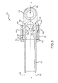
FIG. 2A illustrates a cross-sectional view of a composite tube assembly, in accordance with various embodiments; -
FIG. 2B illustrates a cross-sectional view of a composite tube assembly, in accordance with various embodiments; -
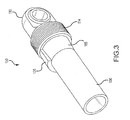
FIG. 3 illustrates a view of a composite tube assembly, in accordance with various embodiments; -
FIG. 4 illustrates a cross-sectional view of a composite tube assembly under a tensile load, in accordance with various embodiments; -
FIG. 5 illustrates a cross-sectional view of a composite tube assembly under a compressive load, in accordance with various embodiments; -
FIG. 6 illustrates a composite tube assembly, in accordance with various embodiments; -
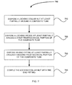
FIG. 7 illustrates a method of manufacture, in accordance with various embodiments; -
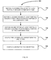
FIG. 8 illustrates a method of manufacture, in accordance with various embodiments; and -
FIG. 9 illustrates a method of manufacture, in accordance with various embodiments. - The detailed description of exemplary embodiments herein makes reference to the accompanying drawings, which show exemplary embodiments by way of illustration and their best mode. While these exemplary embodiments are described in sufficient detail to enable those skilled in the art to practice the disclosure, it should be understood that other embodiments may be realized and that logical, chemical, and mechanical changes may be made without departing from the scope of the disclosure. Thus, the detailed description herein is presented for purposes of illustration only and not of limitation. For example, the steps recited in any of the method or process descriptions may be executed in any order and are not necessarily limited to the order presented. Furthermore, any reference to singular includes plural embodiments, and any reference to more than one component or step may include a singular embodiment or step. Also, any reference to attached, fixed, connected or the like may include permanent, removable, temporary, partial, full and/or any other possible attachment option. Additionally, any reference to "without contact" (or similar phrases) may also include reduced contact or minimal contact.
- With reference to
FIG. 1 , acomposite tube assembly 100, in accordance with various embodiments, is illustrated.Composite tube assembly 100 may comprise acomposite tube 130, alocking collar nut 150, and anend fitting 110. According to various embodiments, as illustrated inFIGs. 1 and6 ,composite tube assembly 100 may comprise alocking key 140 disposed inkeyway 142 ofend fitting 110. In various embodiments, thelocking key 140 may be coupled to lockingcollar nut 150 and, thus, may aid in securinglocking collar nut 150 to end fitting 110. - For example, with temporary reference to
FIG. 6 ,composite tube assembly 100 is illustrated with thelocking collar nut 150 removed for improved clarity. In variousembodiments locking key 140 may be disposed inkeyway 142 ofend fitting 110. In various embodiments,locking key 140 may prevent rotation of locking collar nut 150 (shown inFIG. 1 ) onthreads 114 ofend fitting 110. Thus, in various embodiments, after lockingcollar nut 150 is coupled (e.g., threadedly engaged) to the end fitting 110,locking key 140 may be disposed inkeyway 142. Thus, according to various embodiments, lockingkey 140 may aid in securing (e.g., preventing the rotation of) lockingcollar nut 150 with respect to end fitting 110. - In various embodiments and with reference to
FIG. 1 ,composite tube assembly 100 may comprise ajam nut 145 circumferentially disposed aroundend fitting 110. Thus, in various embodiments, the relative placement of end fitting 110,locking collar nut 150, andjam nut 145, may aid incoupling locking key 140 to lockingcollar nut 150. According to various embodiments,jam nut 145 may be threadedly engaged to the end fitting 110. Thus, in various embodiments and as illustrated inFIG. 1 , thelocking key 140 may be secured inkeyway 142 of end fitting 110 due to the placement of thejam nut 145 and thelocking collar nut 150. - According to various embodiments,
composite tube 130 may comprise lightweight polymer-matrix composite ("PMC") materials to utilize the anisotropic properties of the PMC material. As used herein, PMC materials may include carbon-fiber-reinforced polymers, such as carbon-fiber-reinforced plastics and carbon-fiber reinforced thermoplastics, whether now known or hereinafter developed. As used herein, the term "carbon-fiber-reinforced polymer" may include any now known or hereinafter developed material that comprises a fibrous material network (such as a network of carbon fiber) and a polymer, such as graphite epoxy. According to various embodiments, the PMC material may comprise any now known or hereinafter developed fibers. For example, in various embodiments, PMC materials may comprise aramid fibers and/or para-aramid, such as Kevlar®, a registered mark of the E. I. Du Pont de Nemours and Company, Nomex®, also a registered mark of the E. I. Du Pont de Nemours and Company, and Technora®, a registered mark of the Teijin Corporation. - According to various embodiments, the
end fitting 110 is not particularly limited. According to various embodiments, the end fitting 110 may comprise at least one of a clevis, a single bearing lug, or other known or hereinafter developed geometries for end fittings. In various embodiments, theend fitting 110 may comprise various materials, for example, a metal. Exemplary metals according to various embodiments include at least one of aluminum, tungsten, titanium, nickel, molybdenum, steel, cobalt, chromium, or alloys thereof. For example, according to various embodiments, theend fitting 110 may comprise various steel alloys, such as high strength low alloy steel ("HSLA") that is commercially known as 300M, and/or high strength steel, such as Aermet® 100, a registered trademark of the Carpenter Technology Corporation, and/or titanium alloys, such as Ti 6Al-4V, commercially available from the Titanium Metal Corporation as Ti 6Al-4V ELI. - In various embodiments, the
locking collar nut 150 is not particularly limited. In various embodiments, thelocking collar nut 150 may comprise various materials, for example, a metal. Exemplary metals according to various embodiments include at least one of aluminum, tungsten, titanium, nickel, molybdenum, steel, cobalt, chromium, or alloys thereof. For example, according to various embodiments, thelocking collar nut 150 may comprise various materials, for example, steel alloys, such as high strength low alloy steel ("HSLA") that is commercially known as 300M, and/or high strength steel, such as Aermet® 100, a registered trademark of the Carpenter Technology Corporation, and/or titanium alloys, such as Ti 6Al-4V, commercially available from the Titanium Metal Corporation as Ti 6Al-4V ELI. - With reference to
FIGs. 2A and2B , various cross-sectional views ofcomposite tube assembly 100, in accordance with various embodiments, are illustrated. As can be seen inFIGs. 2A and2B ,composite tube assembly 100 may comprise acomposite tube 130 comprising a variable diameter portion comprising a firstfrustoconical portion 165 and a secondfrustoconical portion 160. According to various embodiments, and as illustrated inFIGs. 2A and2B , a diameter of thecomposite tube 130 at an interface between the firstfrustoconical portion 165 and the secondfrustoconical portion 160 may have a maximum diameter value (illustrated with diameter 16) with respect to the firstfrustoconical portion 165 and may have a maximum diameter value with respect to the secondfrustoconical portion 160. For example, with continued reference toFIGs. 2A and2B ,maximum diameter 16 of firstfrustoconical portion 165 may be greater than another diameter of first frustoconical portion 165 (illustrated with diameter 15). - In various embodiments, an outer surface of the first
frustoconical portion 165 and the secondfrustoconical portion 160 may be surface treated with any known or hereinafter developed methods of surface treatment for PMC materials (e.g., nanocoated, coated with polytetrafluoroethylene ("PTFE"), coated with a metallic thermal spray, etc.). As used herein, the term "nanocoated" is not particularly limited and may include any now known or hereinafter developed methods of coating PMC materials with nanomaterials, while the term "nanomaterials" refers to a material comprised of particles that have at least one dimension between 3.93700787 · 10-8 inches (1 nanometer) and 3.93700787 10-5 inches (1,000 nanometers). According to various embodiments, various nanocoatings may increase the resistance of thecomposite tube 130 against frictional wear, such as frictional wear from end fitting 110. - With temporary reference to
FIG. 2B , acomposite tube assembly 100 according to various embodiments is illustrated. According to various embodiments, the firstfrustoconical portion 165 and secondfrustoconical portion 160 ofcomposite tube 130 may comprise ametallic insert 163. In various embodiments themetallic insert 163 may be bonded to the composite tube 130 (e.g., with an adhesive). In various embodiments,metallic insert 163 may be co-molded with thecomposite tube 130. In various embodiments, themetallic insert 163 may be co-cured with thecomposite tube 130. Accordingly, in various embodiments, themetallic insert 163 may be both co-molded and co-cured with thecomposite tube 130. As used herein, the term "co-curing" may include simultaneous curing of the composite material with the metallic insert. As used herein, co-molded may include being joined in the same mold. For example, in various embodiments, a metallic insert that is both co-molded and co-cured may be joined in the same mold at the same time with the same epoxy and simultaneously cured with the composite tube. Various adhesives may be used to bond and/or co-cure themetallic insert 163 to thecomposite tube 130 and, thus, in various embodiments, the adhesive is not limited. For example, in various embodiments, the adhesive may include any known or hereinafter developed adhesive suitable for PMC materials, such as an epoxy adhesive. An exemplary epoxy adhesive, according to various embodiments, may include Epovex®, commercially available from Zyvex Performance Materials, Incorporated. - Moreover, the
metallic insert 163 is not particularly limited, and may comprise at least one of aluminum, tungsten, titanium, nickel, molybdenum, steel, cobalt, chromium, or alloys thereof. For example, according to various embodiments, themetallic insert 163 may comprise various steel alloys, such as high strength low alloy steel ("HSLA") that is commercially known as 300M, and/or high strength steel, such asAermet ® 100, a registered trademark of the Carpenter Technology Corporation, and/or titanium alloys, such as Ti 6Al-4V, commercially available from the Titanium Metal Corporation as Ti 6Al-4V ELI. - With reference back to both
FIGs. 2A and2B , in various embodiments, the lockingwedge 120 may disposed at least partially around a circumference of the firstfrustoconical portion 165. In various embodiments, a lockingcollar nut 150 may be disposed at least partially around a circumference of the lockingwedge 120. According to various embodiments, anouter surface 122 of lockingwedge 120 may be configured to be tightly secured byinner surface 152 of lockingcollar nut 150, as shown inFIG. 2A . In various embodiments,composite tube assembly 100 may comprise an end fitting 110 at least partially around a circumference of the secondfrustoconical portion 160. In various embodiments, end fitting 110 may be coupled to thelocking collar nut 150. According to various embodiments, the end fitting 110 may be threadedly engaged with the lockingcollar nut 150. For example,threads 154 of lockingcollar nut 150 may be configured to engage with the correspondingthreads 114 of end fitting 110, as shown inFIG. 2A . - In various embodiments, the locking
wedge 120 is not particularly limited. For example, in various embodiments, the lockingwedge 120 may comprise a single, integral piece. As used herein, the term "integrated" or "integral" may include forming a single continuous piece. In various embodiments, lockingwedge 120 may comprise a plurality of subcomponents (e.g., two halves of a locking wedge). For example, in various embodiments, the lockingwedge 120 may comprise two pieces that were separately manufactured. For example, with reference toFIG. 3 ,composite tube assembly 100 is illustrated with one half of the lockingwedge 120 removed and, thus, illustrates lockingwedge 120 disposed at least partially around a circumference of the firstfrustoconical portion 165 ofcomposite tube 130, while proximate to end fitting 110 andthreads 114. - With reference back to
FIG. 2A , according to various embodiments, lockingcollar nut 150 may help secure the lockingwedge 120 around the firstfrustoconical portion 165. For example, in various embodiments the lockingcollar nut 150 may help to retain various axial loads that may try to separate the lockingwedge 120 from firstfrustoconical portion 165. - For example, with reference to
FIG. 4 , acomposite tube assembly 100 under atensile load 400 in accordance with various embodiments is illustrated. In various embodiments, in response totensile load 400 applied to end fitting 110, a longitudinaltensile load 430 on lockingcollar nut 150 may arise. The longitudinaltensile load 430 on lockingcollar nut 150 may exert a radiallycompressive force 420 on lockingwedge 120 disposed around the firstfrustoconical portion 165 due to the configuration of lockingcollar nut 150 and end fitting 110. As used herein, the term "radially" may include a direction primarily directed towards and/or away from a longitudinal axis of thecomposite tube 130. For example, in various embodiments a radiallycompressive force 420 may be primarily directed towards axis A-A' and, thus, may not necessarily be orthogonal to axis A-A' shown inFIG. 4 . - In various embodiments, due to the configuration of first
frustoconical portion 165 and lockingwedge 120, longitudinaltensile load 430 may exert a radiallyoutward load 440 on lockingwedge 120. Accordingly, the radiallycompressive force 420 and the radiallyoutward load 440 may cause hoop stress on the firstfrustoconical portion 165. In turn, longitudinaltensile load 410 may result on thecomposite tube 130. In various embodiments, thecomposite tube 130 may react totensile load 400 applied to end fitting 110. - With reference to
FIG. 5 , acomposite tube assembly 100 under acompressive load 500, in accordance with various embodiments, is illustrated. In various embodiments,compressive load 500 may be applied to end fitting 110. At times whencompressive load 500 is applied to end fitting 110, thecompressive load 500 may be transferred to the secondfrustoconical portion 160 as an internalcompressive load 530 and an outercompressive load 520. Accordingly, in various embodiments, the internalcompressive load 530 and the outercompressive load 520 may create a tensile hoop stress on thecomposite tube 130 that results in longitudinalcompressive load 510. Thus, in various embodiments, thecomposite tube 130 may react in response tocompressive load 500 applied to end fitting 110. - With reference to
FIG. 7 , amethod 700 of manufacturing acomposite tube assembly 100, according to various embodiments is illustrated. Themethod 700 may comprise disposing alocking collar nut 150 at least partially around a composite tube 130 (step 710). In various embodiments and with temporary reference toFIGs. 2A and2B ,method 700 may be a method of assemblingcomposite tube assembly 100. For example, in various embodiments, thecomposite tube assembly 100 may comprise acomposite tube 130 that comprises ametallic insert 163, as illustrated inFIG. 2B . - With reference back to
FIG. 7 , in various embodiments, themethod 700 may comprise disposing a lockingwedge 120 at least partially around the firstfrustoconical portion 165 of the composite tube 130 (step 720). According to various embodiments,method 700 may comprise disposing an end fitting 110 at least partially around the secondfrustoconical portion 160 of the composite tube 130 (step 730).Method 700 may also comprise coupling thelocking collar nut 150 with the end fitting 110 (step 740). According to various embodiments, the lockingcollar nut 150 may circumferentially surround the lockingwedge 120 disposed around the firstfrustoconical portion 165 of thecomposite tube 130. In various embodiments, the lockingcollar nut 150 may be threadedly engaged to the end fitting 110. - With reference to
FIG. 8 , amethod 800 of manufacturing acomposite tube assembly 100 is illustrated, according to various embodiments.Method 800 may comprise disposing alocking collar nut 150 at least partially around a composite tube 130 (step 710). In various embodiments,method 800 may comprise disposing a lockingwedge 120 at least partially around the firstfrustoconical portion 165 of the composite tube 130 (step 720). According to various embodiments,method 800 may comprise disposing an end fitting 110 at least partially around the secondfrustoconical portion 160 of the composite tube 130 (step 730).Method 800 may also comprise coupling thelocking collar nut 150 with the end fitting 110 (step 740), in accordance with various embodiments. In various embodiments,method 800 may also comprise coupling a locking key 140 to thelocking collar nut 150 and the end fitting 110 (step 850). For example, as illustrated inFIG. 1 . - With reference to
FIG. 9 , amethod 900 of manufacturing acomposite tube assembly 100 is illustrated, according to various embodiments.Method 900 may comprise disposing alocking collar nut 150 at least partially around a composite tube 130 (step 710). In various embodiments, amethod 900 may comprise disposing a lockingwedge 120 at least partially around the firstfrustoconical portion 165 of the composite tube 130 (step 720). According to various embodiments, amethod 900 may comprise disposing an end fitting 110 at least partially around the secondfrustoconical portion 160 of the composite tube 130 (step 730).Method 900 may also comprise coupling thelocking collar nut 150 with the end fitting 110 (step 740), in accordance with various embodiments. In various embodiments, themethod 900 may also comprise coupling ajam nut 145 to the end fitting 110 (step 950), for example, as illustrated inFIG. 1 . For example, thejam nut 145 may be threadedly engaged to the end fitting 110. - Benefits, other advantages, and solutions to problems have been described herein with regard to specific embodiments. Furthermore, the connecting lines shown in the various figures contained herein are intended to represent exemplary functional relationships and/or physical couplings between the various elements. It should be noted that many alternative or additional functional relationships or physical connections may be present in a practical system. However, the benefits, advantages, solutions to problems, and any elements that may cause any benefit, advantage, or solution to occur or become more pronounced are not to be construed as critical, required, or essential features or elements of the disclosed embodiments. The scope of the claimed embodiments is accordingly to be limited by nothing other than the appended claims, in which reference to an element in the singular is not intended to mean "one and only one" unless explicitly so stated, but rather "one or more." Moreover, where a phrase similar to "at least one of A, B, or C" is used in the claims, it is intended that the phrase be interpreted to mean that A alone may be present in an embodiment, B alone may be present in an embodiment, C alone may be present in an embodiment, or that any combination of the elements A, B and C may be present in a single embodiment; for example, A and B, A and C, B and C, or A and B and C. Different cross-hatching is used throughout the figures to denote different parts but not necessarily to denote the same or different materials.
- Systems, methods and apparatus are provided herein. In the detailed description herein, references to "one embodiment", "an embodiment", "an example embodiment", etc., indicate that the embodiment described may include a particular feature, structure, or characteristic, but every embodiment may not necessarily include the particular feature, structure, or characteristic. Moreover, such phrases are not necessarily referring to the same embodiment. Further, when a particular feature, structure, or characteristic is described in connection with an embodiment, it is submitted that it is within the knowledge of one skilled in the art to affect such feature, structure, or characteristic in connection with other embodiments whether or not explicitly described. After reading the description, it will be apparent to one skilled in the relevant art(s) how to implement the disclosure in alternative embodiments.
- Furthermore, no element, component, or method step in the present disclosure is intended to be dedicated to the public regardless of whether the element, component, or method step is explicitly recited in the claims. No claim element herein is to be construed under the provisions of 35 U.S.C. § 112(f), unless the element is expressly recited using the phrase "means for." As used herein, the terms "comprises", "comprising", or any other variation thereof, are intended to cover a non-exclusive inclusion, such that a process, method, article, or apparatus that comprises a list of elements does not include only those elements but may include other elements not expressly listed or inherent to such process, method, article, or apparatus.
Claims (14)
- A composite tube assembly (100) comprising:a composite tube (130) comprising a variable diameter portion comprising a first frustoconical portion (165) and a second frustoconical portion (160),wherein a diameter of the composite tube (130) at an interface between the first frustoconical portion (165) and the second frustoconical portion (160) is a maximum diameter value (16) with respect to the first frustoconical portion (165) and is a maximum diameter value (16) with respect to the second frustoconical portion (160);a locking wedge (120) disposed at least partially around a circumference of the first frustoconical portion (165);a locking collar nut (150) disposed at least partially around a circumference of the locking wedge (120); andan end fitting (110) disposed at least partially around a circumference of the second frustoconical portion (160), wherein the end fitting (110) is coupled to the locking collar nut (150).
- The composite tube assembly of claim 1, wherein the end fitting (110) is threadedly engaged with the locking collar nut (150).
- The composite tube assembly of claim 1 or 2, wherein the locking wedge (120) comprises a plurality of subcomponents.
- The composite tube assembly of claim 1 or 2, wherein the locking wedge (120) comprises one single integral piece.
- The composite tube assembly of any preceding claim, further comprising a locking key (140) in contact with the locking collar nut (150) and the end fitting (110).
- The composite tube assembly of any preceding claim, further comprising a jam nut (145) threadedly engaged to the end fitting (110).
- The composite tube assembly of any preceding claim, wherein an outer surface of the first frustoconical portion (165) and an outer surface of the second frustoconical portion (160) are nanocoated.
- The composite tube assembly of any preceding claim, wherein the first frustoconical portion (165) and the second frustoconical portion (160) comprise a metallic insert (163).
- The composite tube assembly of claim 8, wherein the metallic insert (163) is at least one of co-molded, bonded, and co-cured with the composite tube (130).
- The composite tube assembly of claim 8 or 9, wherein the metallic insert (163) comprises at least one of aluminum, tungsten, titanium, nickel, molybdenum, steel, cobalt, chromium, or alloys thereof.
- A method of manufacture comprising:disposing a locking collar nut (150) at least partially around a composite tube (130),wherein the composite tube (130) comprises a variable diameter portion comprising a first frustoconical portion (165) and a second frustoconical portion (160),wherein a diameter of the composite tube (130) at an interface between the first frustoconical portion (165) and the second frustoconical portion (160) is a maximum diameter value (16) with respect to the first frustoconical portion (165) and is a maximum diameter value (16) with respect to the second frustoconical portion (160);disposing a locking wedge (120) at least partially around the first frustoconical portion (165);disposing an end fitting (110) at least partially around the second frustoconical portion (160); andcoupling the locking collar nut (150) with the end fitting (110), wherein the locking collar nut (150) circumferentially surrounds the locking wedge (120) disposed around the first frustoconical portion (165).
- The method of claim 11, wherein the locking collar nut (150) is threadedly engaged to the end fitting (110).
- The method of claim 11 or 12, further comprising coupling a locking key (140) to the locking collar nut (150) and the end fitting (110).
- The method of claim 11, 12 or 13, further comprising coupling a jam nut (145) to the end fitting (110).
Applications Claiming Priority (1)
| Application Number | Priority Date | Filing Date | Title |
|---|---|---|---|
| US14/293,631 US9568040B2 (en) | 2014-06-02 | 2014-06-02 | Struts and methods utilizing a locking collar nut |
Publications (2)
| Publication Number | Publication Date |
|---|---|
| EP2952795A1 true EP2952795A1 (en) | 2015-12-09 |
| EP2952795B1 EP2952795B1 (en) | 2019-12-25 |
Family
ID=53404338
Family Applications (1)
| Application Number | Title | Priority Date | Filing Date |
|---|---|---|---|
| EP15169892.5A Active EP2952795B1 (en) | 2014-06-02 | 2015-05-29 | Composite tube assembly and method of manufacturing the same |
Country Status (2)
| Country | Link |
|---|---|
| US (3) | US9568040B2 (en) |
| EP (1) | EP2952795B1 (en) |
Cited By (2)
| Publication number | Priority date | Publication date | Assignee | Title |
|---|---|---|---|---|
| EP3306117A1 (en) * | 2016-10-05 | 2018-04-11 | Goodrich Corporation | Hybrid metallic/composite joint with enhanced strength |
| FR3165705A1 (en) * | 2025-06-27 | 2026-02-27 | Airbus Operations (S.A.S.) | DOUBLE CYLINDRICAL CONNECTING ROD |
Families Citing this family (15)
| Publication number | Priority date | Publication date | Assignee | Title |
|---|---|---|---|---|
| US9568040B2 (en) | 2014-06-02 | 2017-02-14 | Goodrich Corporation | Struts and methods utilizing a locking collar nut |
| US10272991B2 (en) * | 2016-06-23 | 2019-04-30 | Goodrich Corporation | Metallic composite joint |
| CN107719627B (en) | 2016-08-12 | 2021-05-04 | 中光电智能机器人股份有限公司 | flying device |
| US10927883B2 (en) * | 2017-07-11 | 2021-02-23 | Goodrich Corporation | Composite joint assembly |
| EP3480107A1 (en) | 2017-10-27 | 2019-05-08 | Airbus Operations GmbH | Aircraft framework assembly, aircraft structural framework and aircraft with an aircraft structural framework |
| US11156245B2 (en) | 2018-01-08 | 2021-10-26 | Goodrich Corporation | Hybrid metallic/composite axial tension/compression lobe joint |
| EP3552851A1 (en) * | 2018-04-09 | 2019-10-16 | Engineering Developments for Automotive Industry, S.L. | Fixing device for fixing a stabilizer link to a hollow bar |
| US10823213B2 (en) * | 2018-06-08 | 2020-11-03 | Goodrich Corporation | Composite joint assembly |
| JP7148333B2 (en) | 2018-09-07 | 2022-10-05 | ナブテスコ株式会社 | Bonding of fiber-containing composites |
| US11534984B2 (en) | 2019-04-09 | 2022-12-27 | Goodrich Corporation | Hybrid metallic/composite joint with integral bearing |
| US11512738B2 (en) | 2019-04-11 | 2022-11-29 | Goodrich Corporation | Hybrid metallic/composite joint with separate internal bearing |
| US10626917B1 (en) | 2019-04-11 | 2020-04-21 | Goodrich Corporation | Hybrid metallic/composite joint with separate internal bearing |
| CN110735981B (en) * | 2019-11-28 | 2021-07-09 | 衡阳科盈钢管有限公司 | An improved steel pipe connector |
| CN112762264A (en) * | 2021-01-22 | 2021-05-07 | 刘攀 | Anti-corrosion steel-plastic composite pipe |
| US20250251003A1 (en) * | 2024-02-01 | 2025-08-07 | B/E Aerospace, Inc. | Joint for composite tubular rods |
Citations (3)
| Publication number | Priority date | Publication date | Assignee | Title |
|---|---|---|---|---|
| DE29520478U1 (en) * | 1995-12-23 | 1996-02-15 | Hewing GmbH, 48607 Ochtrup | Mechanical connection of a pipe fitting to a multi-layer composite pipe |
| WO2004027305A1 (en) * | 2002-09-20 | 2004-04-01 | Swagelok Company | Integral end connection for tube fitting |
| US6945569B1 (en) * | 2004-04-28 | 2005-09-20 | S.P.M. Flow Control, Inc. | Enhanced durability hammer union |
Family Cites Families (11)
| Publication number | Priority date | Publication date | Assignee | Title |
|---|---|---|---|---|
| US1076921A (en) * | 1911-03-29 | 1913-10-28 | Wayne Stafford | Ball-and-socket pipe-union. |
| US2404142A (en) * | 1940-09-14 | 1946-07-16 | Logansport Machine Inc | Tube coupling |
| GB1182914A (en) * | 1969-01-08 | 1970-03-04 | Rolls Royce | Pipe Termination. |
| US4647078A (en) | 1985-12-19 | 1987-03-03 | Hercules, Incorporated | Metal to composite tubular joints |
| DE3709819A1 (en) * | 1986-05-12 | 1987-11-19 | Waluga Armaturen | PIPE FITTING |
| FR2637952B1 (en) | 1988-10-13 | 1991-01-04 | Aerospatiale | DEVICE FOR CONNECTING THE END OF A COMPOSITE TUBE HIGHLY AXILICALLY SOLICITED WITH METAL FLANGES AND ITS MANUFACTURING METHOD |
| WO2003089145A2 (en) | 2002-04-19 | 2003-10-30 | Bell Helicopter Textron Inc. | Composite drive shaft with captured end adapters |
| US8414724B2 (en) | 2006-12-02 | 2013-04-09 | The Boeing Company | Composite tube having cobonded end fittings and method of making same |
| US8161619B2 (en) | 2007-11-02 | 2012-04-24 | The Boeing Company | Joint for hybrid composite items |
| DE102013008810B4 (en) * | 2012-06-13 | 2016-06-23 | Ralph Funck | Force transmission in fiber composite pipes |
| US9568040B2 (en) | 2014-06-02 | 2017-02-14 | Goodrich Corporation | Struts and methods utilizing a locking collar nut |
-
2014
- 2014-06-02 US US14/293,631 patent/US9568040B2/en active Active
-
2015
- 2015-05-29 EP EP15169892.5A patent/EP2952795B1/en active Active
-
2016
- 2016-12-21 US US15/386,849 patent/US10294973B2/en active Active
- 2016-12-21 US US15/386,803 patent/US10288101B2/en active Active
Patent Citations (3)
| Publication number | Priority date | Publication date | Assignee | Title |
|---|---|---|---|---|
| DE29520478U1 (en) * | 1995-12-23 | 1996-02-15 | Hewing GmbH, 48607 Ochtrup | Mechanical connection of a pipe fitting to a multi-layer composite pipe |
| WO2004027305A1 (en) * | 2002-09-20 | 2004-04-01 | Swagelok Company | Integral end connection for tube fitting |
| US6945569B1 (en) * | 2004-04-28 | 2005-09-20 | S.P.M. Flow Control, Inc. | Enhanced durability hammer union |
Cited By (3)
| Publication number | Priority date | Publication date | Assignee | Title |
|---|---|---|---|---|
| EP3306117A1 (en) * | 2016-10-05 | 2018-04-11 | Goodrich Corporation | Hybrid metallic/composite joint with enhanced strength |
| US10781839B2 (en) | 2016-10-05 | 2020-09-22 | Goodrich Corporation | Hybrid metallic/composite joint with enhanced strength |
| FR3165705A1 (en) * | 2025-06-27 | 2026-02-27 | Airbus Operations (S.A.S.) | DOUBLE CYLINDRICAL CONNECTING ROD |
Also Published As
| Publication number | Publication date |
|---|---|
| US10288101B2 (en) | 2019-05-14 |
| EP2952795B1 (en) | 2019-12-25 |
| US9568040B2 (en) | 2017-02-14 |
| US20170102024A1 (en) | 2017-04-13 |
| US20150345673A1 (en) | 2015-12-03 |
| US10294973B2 (en) | 2019-05-21 |
| US20170102019A1 (en) | 2017-04-13 |
Similar Documents
| Publication | Publication Date | Title |
|---|---|---|
| US10294973B2 (en) | Struts and methods utilizing a locking collar nut | |
| EP2930377B1 (en) | Struts and methods utilizing a compression collar | |
| US9726325B2 (en) | Composite tube assemblies and methods | |
| EP3382221B1 (en) | Composite end connections | |
| US10539174B2 (en) | Composite joint assembly | |
| EP3133298B1 (en) | Connector | |
| EP3427927B1 (en) | Composite joint assembly | |
| CA3020938A1 (en) | Transmission shaft | |
| EP3260369B1 (en) | Metallic composite joint | |
| US12092137B2 (en) | Hybrid metallic/composite joint with enhanced strength | |
| EP3263448B1 (en) | Manufacturing method of polymer composite/metal load transfer joint for landing gear | |
| US10823213B2 (en) | Composite joint assembly | |
| CN108386427B (en) | Insert for joining components | |
| US11378215B2 (en) | Apparatus for duct connection | |
| EP3587888B1 (en) | Composite tube connector assembly |
Legal Events
| Date | Code | Title | Description |
|---|---|---|---|
| PUAI | Public reference made under article 153(3) epc to a published international application that has entered the european phase |
Free format text: ORIGINAL CODE: 0009012 |
|
| AK | Designated contracting states |
Kind code of ref document: A1 Designated state(s): AL AT BE BG CH CY CZ DE DK EE ES FI FR GB GR HR HU IE IS IT LI LT LU LV MC MK MT NL NO PL PT RO RS SE SI SK SM TR |
|
| AX | Request for extension of the european patent |
Extension state: BA ME |
|
| 17P | Request for examination filed |
Effective date: 20160609 |
|
| RBV | Designated contracting states (corrected) |
Designated state(s): AL AT BE BG CH CY CZ DE DK EE ES FI FR GB GR HR HU IE IS IT LI LT LU LV MC MK MT NL NO PL PT RO RS SE SI SK SM TR |
|
| STAA | Information on the status of an ep patent application or granted ep patent |
Free format text: STATUS: EXAMINATION IS IN PROGRESS |
|
| 17Q | First examination report despatched |
Effective date: 20181012 |
|
| REG | Reference to a national code |
Ref country code: DE Ref legal event code: R079 Ref document number: 602015044152 Country of ref document: DE Free format text: PREVIOUS MAIN CLASS: F16L0019025000 Ipc: B64C0001060000 |
|
| RIC1 | Information provided on ipc code assigned before grant |
Ipc: F16C 11/06 20060101ALI20190528BHEP Ipc: F16C 7/02 20060101ALI20190528BHEP Ipc: B64C 1/06 20060101AFI20190528BHEP Ipc: F16B 7/18 20060101ALI20190528BHEP Ipc: F16B 7/02 20060101ALI20190528BHEP |
|
| GRAP | Despatch of communication of intention to grant a patent |
Free format text: ORIGINAL CODE: EPIDOSNIGR1 |
|
| STAA | Information on the status of an ep patent application or granted ep patent |
Free format text: STATUS: GRANT OF PATENT IS INTENDED |
|
| INTG | Intention to grant announced |
Effective date: 20190710 |
|
| GRAS | Grant fee paid |
Free format text: ORIGINAL CODE: EPIDOSNIGR3 |
|
| GRAA | (expected) grant |
Free format text: ORIGINAL CODE: 0009210 |
|
| STAA | Information on the status of an ep patent application or granted ep patent |
Free format text: STATUS: THE PATENT HAS BEEN GRANTED |
|
| AK | Designated contracting states |
Kind code of ref document: B1 Designated state(s): AL AT BE BG CH CY CZ DE DK EE ES FI FR GB GR HR HU IE IS IT LI LT LU LV MC MK MT NL NO PL PT RO RS SE SI SK SM TR |
|
| REG | Reference to a national code |
Ref country code: GB Ref legal event code: FG4D |
|
| REG | Reference to a national code |
Ref country code: CH Ref legal event code: EP |
|
| REG | Reference to a national code |
Ref country code: DE Ref legal event code: R096 Ref document number: 602015044152 Country of ref document: DE |
|
| REG | Reference to a national code |
Ref country code: AT Ref legal event code: REF Ref document number: 1216843 Country of ref document: AT Kind code of ref document: T Effective date: 20200115 |
|
| REG | Reference to a national code |
Ref country code: IE Ref legal event code: FG4D |
|
| REG | Reference to a national code |
Ref country code: NL Ref legal event code: MP Effective date: 20191225 |
|
| PG25 | Lapsed in a contracting state [announced via postgrant information from national office to epo] |
Ref country code: BG Free format text: LAPSE BECAUSE OF FAILURE TO SUBMIT A TRANSLATION OF THE DESCRIPTION OR TO PAY THE FEE WITHIN THE PRESCRIBED TIME-LIMIT Effective date: 20200325 Ref country code: FI Free format text: LAPSE BECAUSE OF FAILURE TO SUBMIT A TRANSLATION OF THE DESCRIPTION OR TO PAY THE FEE WITHIN THE PRESCRIBED TIME-LIMIT Effective date: 20191225 Ref country code: SE Free format text: LAPSE BECAUSE OF FAILURE TO SUBMIT A TRANSLATION OF THE DESCRIPTION OR TO PAY THE FEE WITHIN THE PRESCRIBED TIME-LIMIT Effective date: 20191225 Ref country code: LV Free format text: LAPSE BECAUSE OF FAILURE TO SUBMIT A TRANSLATION OF THE DESCRIPTION OR TO PAY THE FEE WITHIN THE PRESCRIBED TIME-LIMIT Effective date: 20191225 Ref country code: NO Free format text: LAPSE BECAUSE OF FAILURE TO SUBMIT A TRANSLATION OF THE DESCRIPTION OR TO PAY THE FEE WITHIN THE PRESCRIBED TIME-LIMIT Effective date: 20200325 Ref country code: GR Free format text: LAPSE BECAUSE OF FAILURE TO SUBMIT A TRANSLATION OF THE DESCRIPTION OR TO PAY THE FEE WITHIN THE PRESCRIBED TIME-LIMIT Effective date: 20200326 Ref country code: LT Free format text: LAPSE BECAUSE OF FAILURE TO SUBMIT A TRANSLATION OF THE DESCRIPTION OR TO PAY THE FEE WITHIN THE PRESCRIBED TIME-LIMIT Effective date: 20191225 |
|
| REG | Reference to a national code |
Ref country code: LT Ref legal event code: MG4D |
|
| PG25 | Lapsed in a contracting state [announced via postgrant information from national office to epo] |
Ref country code: HR Free format text: LAPSE BECAUSE OF FAILURE TO SUBMIT A TRANSLATION OF THE DESCRIPTION OR TO PAY THE FEE WITHIN THE PRESCRIBED TIME-LIMIT Effective date: 20191225 Ref country code: RS Free format text: LAPSE BECAUSE OF FAILURE TO SUBMIT A TRANSLATION OF THE DESCRIPTION OR TO PAY THE FEE WITHIN THE PRESCRIBED TIME-LIMIT Effective date: 20191225 |
|
| PG25 | Lapsed in a contracting state [announced via postgrant information from national office to epo] |
Ref country code: AL Free format text: LAPSE BECAUSE OF FAILURE TO SUBMIT A TRANSLATION OF THE DESCRIPTION OR TO PAY THE FEE WITHIN THE PRESCRIBED TIME-LIMIT Effective date: 20191225 |
|
| PG25 | Lapsed in a contracting state [announced via postgrant information from national office to epo] |
Ref country code: NL Free format text: LAPSE BECAUSE OF FAILURE TO SUBMIT A TRANSLATION OF THE DESCRIPTION OR TO PAY THE FEE WITHIN THE PRESCRIBED TIME-LIMIT Effective date: 20191225 Ref country code: EE Free format text: LAPSE BECAUSE OF FAILURE TO SUBMIT A TRANSLATION OF THE DESCRIPTION OR TO PAY THE FEE WITHIN THE PRESCRIBED TIME-LIMIT Effective date: 20191225 Ref country code: RO Free format text: LAPSE BECAUSE OF FAILURE TO SUBMIT A TRANSLATION OF THE DESCRIPTION OR TO PAY THE FEE WITHIN THE PRESCRIBED TIME-LIMIT Effective date: 20191225 Ref country code: PT Free format text: LAPSE BECAUSE OF FAILURE TO SUBMIT A TRANSLATION OF THE DESCRIPTION OR TO PAY THE FEE WITHIN THE PRESCRIBED TIME-LIMIT Effective date: 20200520 Ref country code: CZ Free format text: LAPSE BECAUSE OF FAILURE TO SUBMIT A TRANSLATION OF THE DESCRIPTION OR TO PAY THE FEE WITHIN THE PRESCRIBED TIME-LIMIT Effective date: 20191225 |
|
| PG25 | Lapsed in a contracting state [announced via postgrant information from national office to epo] |
Ref country code: SM Free format text: LAPSE BECAUSE OF FAILURE TO SUBMIT A TRANSLATION OF THE DESCRIPTION OR TO PAY THE FEE WITHIN THE PRESCRIBED TIME-LIMIT Effective date: 20191225 Ref country code: IS Free format text: LAPSE BECAUSE OF FAILURE TO SUBMIT A TRANSLATION OF THE DESCRIPTION OR TO PAY THE FEE WITHIN THE PRESCRIBED TIME-LIMIT Effective date: 20200425 Ref country code: SK Free format text: LAPSE BECAUSE OF FAILURE TO SUBMIT A TRANSLATION OF THE DESCRIPTION OR TO PAY THE FEE WITHIN THE PRESCRIBED TIME-LIMIT Effective date: 20191225 |
|
| REG | Reference to a national code |
Ref country code: DE Ref legal event code: R097 Ref document number: 602015044152 Country of ref document: DE |
|
| PG25 | Lapsed in a contracting state [announced via postgrant information from national office to epo] |
Ref country code: DK Free format text: LAPSE BECAUSE OF FAILURE TO SUBMIT A TRANSLATION OF THE DESCRIPTION OR TO PAY THE FEE WITHIN THE PRESCRIBED TIME-LIMIT Effective date: 20191225 Ref country code: ES Free format text: LAPSE BECAUSE OF FAILURE TO SUBMIT A TRANSLATION OF THE DESCRIPTION OR TO PAY THE FEE WITHIN THE PRESCRIBED TIME-LIMIT Effective date: 20191225 |
|
| PLBE | No opposition filed within time limit |
Free format text: ORIGINAL CODE: 0009261 |
|
| STAA | Information on the status of an ep patent application or granted ep patent |
Free format text: STATUS: NO OPPOSITION FILED WITHIN TIME LIMIT |
|
| REG | Reference to a national code |
Ref country code: AT Ref legal event code: MK05 Ref document number: 1216843 Country of ref document: AT Kind code of ref document: T Effective date: 20191225 |
|
| PG25 | Lapsed in a contracting state [announced via postgrant information from national office to epo] |
Ref country code: SI Free format text: LAPSE BECAUSE OF FAILURE TO SUBMIT A TRANSLATION OF THE DESCRIPTION OR TO PAY THE FEE WITHIN THE PRESCRIBED TIME-LIMIT Effective date: 20191225 |
|
| 26N | No opposition filed |
Effective date: 20200928 |
|
| PG25 | Lapsed in a contracting state [announced via postgrant information from national office to epo] |
Ref country code: MC Free format text: LAPSE BECAUSE OF FAILURE TO SUBMIT A TRANSLATION OF THE DESCRIPTION OR TO PAY THE FEE WITHIN THE PRESCRIBED TIME-LIMIT Effective date: 20191225 Ref country code: IT Free format text: LAPSE BECAUSE OF FAILURE TO SUBMIT A TRANSLATION OF THE DESCRIPTION OR TO PAY THE FEE WITHIN THE PRESCRIBED TIME-LIMIT Effective date: 20191225 Ref country code: AT Free format text: LAPSE BECAUSE OF FAILURE TO SUBMIT A TRANSLATION OF THE DESCRIPTION OR TO PAY THE FEE WITHIN THE PRESCRIBED TIME-LIMIT Effective date: 20191225 Ref country code: LI Free format text: LAPSE BECAUSE OF NON-PAYMENT OF DUE FEES Effective date: 20200531 Ref country code: CH Free format text: LAPSE BECAUSE OF NON-PAYMENT OF DUE FEES Effective date: 20200531 |
|
| PG25 | Lapsed in a contracting state [announced via postgrant information from national office to epo] |
Ref country code: PL Free format text: LAPSE BECAUSE OF FAILURE TO SUBMIT A TRANSLATION OF THE DESCRIPTION OR TO PAY THE FEE WITHIN THE PRESCRIBED TIME-LIMIT Effective date: 20191225 |
|
| REG | Reference to a national code |
Ref country code: BE Ref legal event code: MM Effective date: 20200531 |
|
| GBPC | Gb: european patent ceased through non-payment of renewal fee |
Effective date: 20200529 |
|
| PG25 | Lapsed in a contracting state [announced via postgrant information from national office to epo] |
Ref country code: LU Free format text: LAPSE BECAUSE OF NON-PAYMENT OF DUE FEES Effective date: 20200529 |
|
| PG25 | Lapsed in a contracting state [announced via postgrant information from national office to epo] |
Ref country code: IE Free format text: LAPSE BECAUSE OF NON-PAYMENT OF DUE FEES Effective date: 20200529 Ref country code: GB Free format text: LAPSE BECAUSE OF NON-PAYMENT OF DUE FEES Effective date: 20200529 |
|
| PG25 | Lapsed in a contracting state [announced via postgrant information from national office to epo] |
Ref country code: BE Free format text: LAPSE BECAUSE OF NON-PAYMENT OF DUE FEES Effective date: 20200531 |
|
| PG25 | Lapsed in a contracting state [announced via postgrant information from national office to epo] |
Ref country code: TR Free format text: LAPSE BECAUSE OF FAILURE TO SUBMIT A TRANSLATION OF THE DESCRIPTION OR TO PAY THE FEE WITHIN THE PRESCRIBED TIME-LIMIT Effective date: 20191225 Ref country code: MT Free format text: LAPSE BECAUSE OF FAILURE TO SUBMIT A TRANSLATION OF THE DESCRIPTION OR TO PAY THE FEE WITHIN THE PRESCRIBED TIME-LIMIT Effective date: 20191225 Ref country code: CY Free format text: LAPSE BECAUSE OF FAILURE TO SUBMIT A TRANSLATION OF THE DESCRIPTION OR TO PAY THE FEE WITHIN THE PRESCRIBED TIME-LIMIT Effective date: 20191225 |
|
| PG25 | Lapsed in a contracting state [announced via postgrant information from national office to epo] |
Ref country code: MK Free format text: LAPSE BECAUSE OF FAILURE TO SUBMIT A TRANSLATION OF THE DESCRIPTION OR TO PAY THE FEE WITHIN THE PRESCRIBED TIME-LIMIT Effective date: 20191225 |
|
| P01 | Opt-out of the competence of the unified patent court (upc) registered |
Effective date: 20230522 |
|
| PGFP | Annual fee paid to national office [announced via postgrant information from national office to epo] |
Ref country code: DE Payment date: 20250423 Year of fee payment: 11 |
|
| PGFP | Annual fee paid to national office [announced via postgrant information from national office to epo] |
Ref country code: FR Payment date: 20250423 Year of fee payment: 11 |