EP2952666A1 - Magnetic hinge for an oven door - Google Patents
Magnetic hinge for an oven door Download PDFInfo
- Publication number
- EP2952666A1 EP2952666A1 EP15167649.1A EP15167649A EP2952666A1 EP 2952666 A1 EP2952666 A1 EP 2952666A1 EP 15167649 A EP15167649 A EP 15167649A EP 2952666 A1 EP2952666 A1 EP 2952666A1
- Authority
- EP
- European Patent Office
- Prior art keywords
- housing
- magnet
- input arm
- hinge
- door
- Prior art date
- Legal status (The legal status is an assumption and is not a legal conclusion. Google has not performed a legal analysis and makes no representation as to the accuracy of the status listed.)
- Granted
Links
- 230000008878 coupling Effects 0.000 claims abstract description 10
- 238000010168 coupling process Methods 0.000 claims abstract description 10
- 238000005859 coupling reaction Methods 0.000 claims abstract description 10
- 230000007423 decrease Effects 0.000 claims abstract description 6
- 230000006835 compression Effects 0.000 claims description 9
- 238000007906 compression Methods 0.000 claims description 9
- 230000007246 mechanism Effects 0.000 description 3
- 230000007704 transition Effects 0.000 description 3
- 238000009413 insulation Methods 0.000 description 1
- 230000000284 resting effect Effects 0.000 description 1
- 239000013589 supplement Substances 0.000 description 1
Images


Classifications
-
- E—FIXED CONSTRUCTIONS
- E05—LOCKS; KEYS; WINDOW OR DOOR FITTINGS; SAFES
- E05D—HINGES OR SUSPENSION DEVICES FOR DOORS, WINDOWS OR WINGS
- E05D11/00—Additional features or accessories of hinges
- E05D11/10—Devices for preventing movement between relatively-movable hinge parts
- E05D11/1028—Devices for preventing movement between relatively-movable hinge parts for maintaining the hinge in two or more positions, e.g. intermediate or fully open
- E05D11/105—Devices for preventing movement between relatively-movable hinge parts for maintaining the hinge in two or more positions, e.g. intermediate or fully open the maintaining means acting perpendicularly to the pivot axis
- E05D11/1064—Devices for preventing movement between relatively-movable hinge parts for maintaining the hinge in two or more positions, e.g. intermediate or fully open the maintaining means acting perpendicularly to the pivot axis with a coil spring perpendicular to the pivot axis
-
- E—FIXED CONSTRUCTIONS
- E05—LOCKS; KEYS; WINDOW OR DOOR FITTINGS; SAFES
- E05F—DEVICES FOR MOVING WINGS INTO OPEN OR CLOSED POSITION; CHECKS FOR WINGS; WING FITTINGS NOT OTHERWISE PROVIDED FOR, CONCERNED WITH THE FUNCTIONING OF THE WING
- E05F1/00—Closers or openers for wings, not otherwise provided for in this subclass
- E05F1/08—Closers or openers for wings, not otherwise provided for in this subclass spring-actuated, e.g. for horizontally sliding wings
- E05F1/10—Closers or openers for wings, not otherwise provided for in this subclass spring-actuated, e.g. for horizontally sliding wings for swinging wings, e.g. counterbalance
- E05F1/12—Mechanisms in the shape of hinges or pivots, operated by springs
- E05F1/1246—Mechanisms in the shape of hinges or pivots, operated by springs with a coil spring perpendicular to the pivot axis
- E05F1/1253—Mechanisms in the shape of hinges or pivots, operated by springs with a coil spring perpendicular to the pivot axis with a compression spring
- E05F1/1261—Mechanisms in the shape of hinges or pivots, operated by springs with a coil spring perpendicular to the pivot axis with a compression spring for counterbalancing
-
- E—FIXED CONSTRUCTIONS
- E05—LOCKS; KEYS; WINDOW OR DOOR FITTINGS; SAFES
- E05C—BOLTS OR FASTENING DEVICES FOR WINGS, SPECIALLY FOR DOORS OR WINDOWS
- E05C19/00—Other devices specially designed for securing wings, e.g. with suction cups
- E05C19/16—Devices holding the wing by magnetic or electromagnetic attraction
-
- E—FIXED CONSTRUCTIONS
- E05—LOCKS; KEYS; WINDOW OR DOOR FITTINGS; SAFES
- E05D—HINGES OR SUSPENSION DEVICES FOR DOORS, WINDOWS OR WINGS
- E05D11/00—Additional features or accessories of hinges
- E05D11/0054—Covers, e.g. for protection
-
- E—FIXED CONSTRUCTIONS
- E05—LOCKS; KEYS; WINDOW OR DOOR FITTINGS; SAFES
- E05D—HINGES OR SUSPENSION DEVICES FOR DOORS, WINDOWS OR WINGS
- E05D7/00—Hinges or pivots of special construction
-
- E—FIXED CONSTRUCTIONS
- E05—LOCKS; KEYS; WINDOW OR DOOR FITTINGS; SAFES
- E05F—DEVICES FOR MOVING WINGS INTO OPEN OR CLOSED POSITION; CHECKS FOR WINGS; WING FITTINGS NOT OTHERWISE PROVIDED FOR, CONCERNED WITH THE FUNCTIONING OF THE WING
- E05F1/00—Closers or openers for wings, not otherwise provided for in this subclass
-
- F—MECHANICAL ENGINEERING; LIGHTING; HEATING; WEAPONS; BLASTING
- F16—ENGINEERING ELEMENTS AND UNITS; GENERAL MEASURES FOR PRODUCING AND MAINTAINING EFFECTIVE FUNCTIONING OF MACHINES OR INSTALLATIONS; THERMAL INSULATION IN GENERAL
- F16B—DEVICES FOR FASTENING OR SECURING CONSTRUCTIONAL ELEMENTS OR MACHINE PARTS TOGETHER, e.g. NAILS, BOLTS, CIRCLIPS, CLAMPS, CLIPS OR WEDGES; JOINTS OR JOINTING
- F16B1/00—Devices for securing together, or preventing relative movement between, constructional elements or machine parts
-
- E—FIXED CONSTRUCTIONS
- E05—LOCKS; KEYS; WINDOW OR DOOR FITTINGS; SAFES
- E05D—HINGES OR SUSPENSION DEVICES FOR DOORS, WINDOWS OR WINGS
- E05D11/00—Additional features or accessories of hinges
- E05D11/0054—Covers, e.g. for protection
- E05D2011/0072—Covers, e.g. for protection for the gap between hinge parts
-
- E—FIXED CONSTRUCTIONS
- E05—LOCKS; KEYS; WINDOW OR DOOR FITTINGS; SAFES
- E05Y—INDEXING SCHEME ASSOCIATED WITH SUBCLASSES E05D AND E05F, RELATING TO CONSTRUCTION ELEMENTS, ELECTRIC CONTROL, POWER SUPPLY, POWER SIGNAL OR TRANSMISSION, USER INTERFACES, MOUNTING OR COUPLING, DETAILS, ACCESSORIES, AUXILIARY OPERATIONS NOT OTHERWISE PROVIDED FOR, APPLICATION THEREOF
- E05Y2201/00—Constructional elements; Accessories therefor
- E05Y2201/40—Motors; Magnets; Springs; Weights; Accessories therefor
- E05Y2201/46—Magnets
-
- E—FIXED CONSTRUCTIONS
- E05—LOCKS; KEYS; WINDOW OR DOOR FITTINGS; SAFES
- E05Y—INDEXING SCHEME ASSOCIATED WITH SUBCLASSES E05D AND E05F, RELATING TO CONSTRUCTION ELEMENTS, ELECTRIC CONTROL, POWER SUPPLY, POWER SIGNAL OR TRANSMISSION, USER INTERFACES, MOUNTING OR COUPLING, DETAILS, ACCESSORIES, AUXILIARY OPERATIONS NOT OTHERWISE PROVIDED FOR, APPLICATION THEREOF
- E05Y2900/00—Application of doors, windows, wings or fittings thereof
- E05Y2900/30—Application of doors, windows, wings or fittings thereof for domestic appliances
- E05Y2900/308—Application of doors, windows, wings or fittings thereof for domestic appliances for ovens
-
- F—MECHANICAL ENGINEERING; LIGHTING; HEATING; WEAPONS; BLASTING
- F16—ENGINEERING ELEMENTS AND UNITS; GENERAL MEASURES FOR PRODUCING AND MAINTAINING EFFECTIVE FUNCTIONING OF MACHINES OR INSTALLATIONS; THERMAL INSULATION IN GENERAL
- F16B—DEVICES FOR FASTENING OR SECURING CONSTRUCTIONAL ELEMENTS OR MACHINE PARTS TOGETHER, e.g. NAILS, BOLTS, CIRCLIPS, CLAMPS, CLIPS OR WEDGES; JOINTS OR JOINTING
- F16B2200/00—Constructional details of connections not covered for in other groups of this subclass
- F16B2200/83—Use of a magnetic material
Definitions
- the present invention generally relates to an oven door hinge used to connect the oven door to the main oven unit, and more particularly to an oven door hinge that utilizes magnets to provide a closing force sufficient to keep the door closed against the oven opening.
- Ovens and other appliances having doors that rotate to open by downward rotation generally require hinges connecting the oven door to the main appliance unit that provide a closing force sufficient to keep the door closed against the weight of the door. Such closing force may prevent unintended opening and, in the case of an oven or the like, provide proper insulation.
- the hinges it is also generally desired for the hinges to also provide balancing force sufficient to maintain a partially open position of the door, as desired by the user.
- oven door hinges are configured such that the hinges apply the closing force when the door is at a position within a desired angle from the closed position and such that the balancing force is applied through the remainder of the range of motion provided by the hinge, up until the door is fully opened.
- Oven door hinges have used various mechanisms including combinations of linkages, multiple springs, or cams to provide the desired combination of closing and balancing forces within the desired portions of oven door range of motion. Such mechanisms can be mechanically complex, resulting in high tooling and assembly costs and introducing multiple failure modes. Accordingly further advances for hinges used in ovens and other appliances are desired.
- One aspect of the present disclosure includes a hinge for rotatably coupling an appliance door with an appliance body.
- the hinge includes an input arm affixable with the body and a housing affixable within the door and coupled with the input arm so as to be rotatable through a range of motion between a first position and a second position.
- a spring is operably engaged between the housing and the input arm to apply a balancing torque to the housing arm relative to the input arm.
- a first magnet is fixed relative to the housing, and a second magnet is movably received within the housing and is operatively coupled with the input arm so as to be positioned adjacent the first magnet when the housing is in the first position and moved away from the first magnet by rotation of the housing with respect to the input arm from the first position toward the second position.
- a mutual attraction between the first and second magnets applies a closing torque to the housing relative to the input arm when the housing is within about 25 degrees from the first position.
- an appliance including a body defining an opening with a lower edge, a door positionable over the opening of the body, and a hinge.
- the hinge has an input arm coupled to the body and a housing within the door and rotatably coupled with the input arm such that the door is rotatable adjacent the lower edge of the opening and rotates away from the opening in a vertical direction between a closed position and an open position.
- a spring is operably engaged between the housing and the input arm to apply a balancing torque to the input arm relative to the housing that substantially matches a weight torque of the door about the hinge.
- a first magnet is fixed relative to the housing and a second magnet is operatively coupled with the input arm such that rotation of the housing with respect to the input arm moves the second magnet axially with respect to the first magnet.
- the magnets have a mutual attraction between each other that is operable to apply a closing torque to the input arm relative to the housing to urge to door toward the closed position when the door is within 25 degrees of the closed position.
- Yet another aspect of the present disclosure includes a hinge for rotatably coupling a door with a body including a housing affixable within the door and an input arm coupled to the housing and rotatable through a range of motion between a first position and a second position, the input arm being affixable with the appliance body.
- a spring is operably engaged between the housing and the input arm to apply a balancing torque to the input arm relative to the housing.
- a first magnet is fixed relative to the housing and a second magnet is operatively coupled with the input arm such that rotation of the input arm with respect to the housing moves the second magnet axially with respect to the first magnet.
- the magnets have a mutual attraction between each other that is operable to apply a closing torque to the input arm relative to the housing that decreases from about 70 N-m when the input arm is in the first position to less than about 3 N-m when the door is about 25 degrees from the first position.
- reference numeral 10 generally designates a hinge for rotatably coupling a door 12 of an appliance 14 with a body 16 thereof.
- Hinge 10 includes an input arm 18 affixable with the body 16 and a housing 20 affixable within the door 12 and coupled with the input arm so as to be rotatable through a range of motion 22 ( FIG. 6 ) between a first position (for example, housing 20 c in FIG. 3 ) and a second position (for example, housing 20 o in FIG. 5 ).
- a spring 24 is operably engaged between the housing 20 and the input arm 18 to apply a balancing torque to the housing 20 relative to the input arm 18.
- a first magnet 26 is fixed relative to the housing 20, and a second magnet 28 is movably received within the housing 20 and is operatively coupled with the input arm 18 so as to be positioned adjacent the first magnet 26 when the housing 20 is in the first position and moved away from the first magnet 26 by rotation of the housing 20 with respect to the input 18 arm from the first position toward the second position.
- a mutual attraction between the first and second magnets 26 and 28 applies a closing torque to the housing 20 relative to the input arm 18 when the housing 20 is within about 25 degrees from the first position.
- appliance 14 can be in the form of an oven or another similar appliance wherein a door 12 is mounted to the body 16 of the appliance to cover an opening 32 along a vertical face 34 of the appliance 14, and more particularly, one in which one or more hinges 10 rotatably couple door 12 to the body 16 at a location adjacent a lower edge 36 of the opening 32.
- the hinges 10 provide for rotation of door 12 about a horizontal axis 38 such that the door 10 opens in a vertical direction, downward and away from the opening 32.
- a hinge 10 that is capable of balancing against the weight of a partially opened door through a range of possible positions of door 12 such that a user may open door 12 to a desired, partially-open position that the hinge 10 will maintain.
- hinge 10 can facilitate complete and secure closing of a door 12 over an opening 32 of an appliance 14. This functionality can help to fully close door 12 when a user, for example, brings the door 12 to within a predetermined range proximate to the fully closed position (as indicated by door 12 c in FIG. 2 ). Further hinge 10 can be configured to provide an additional force to help maintain the door 12 in a fully closed position against body 16. This force may supplement the force of the spring 24, which may be low or zero in the instance of a fully closed door 12 c . Both the balancing force and the closing force may be referred to as a balancing torque and a closing torque, as the forces related thereto are applied about axis 38. Aspects of hinge 10 that provide the balancing torque and closing torque are discussed further herein.
- FIGS. 3-5 show an embodiment of a hinge 10 including a spring 24 and a pair of magnets including a first magnet 26 and a second magnet 28.
- a slider 40 extends axially out of an end 42 of housing 20 opposite input arm 18.
- Spring 24 is positioned over and surrounding slider 40 and is captured between end 42 of housing and flange 44 on the opposite end of slider 40 therefrom.
- Slider 40 is operatively coupled with input arm by connector 46, which is rotatably coupled with input arm 18 at a location spaced apart from the rotatable coupling between input arm 18 and housing 20.
- connector 46 moves relative to housing 20 in a direction away from end 42, thereby moving slider 40 in the axial direction 48, as shown in FIG. 4 , in which housing 20a has been rotated relative to input arm 18 by approximately 25°.
- Such movement causes compression of spring 24, thereby increasing the spring force proportionate to the spring coefficient thereof.
- the particular spring coefficient of spring 24 may vary according to the geometry of hinge 10, including the amount of compression imparted on spring 24 by rotation of housing 20 relative to input arm 18, as well as the weight of door 12 such that spring 24 applies the desired balancing torque about axis 38 (which may also include an allowance for internal friction among components). This operation is reversed during closing of door 12.
- each of first magnet 26 and second magnet 28 are positioned within a chamber 50, which is positioned within and connected to housing 20.
- First magnet 26 is fixed within chamber 50
- second magnet 28 is slidably received within chamber 50 so as to be moveable toward and away from first magnet 26.
- a bar 52 is rigidly connected to second magnet 28 and bar 52 is coupled with input arm 18 by link 54.
- Link 54 is rotatably coupled with bar 52 at an end thereof opposite second magnet 28 and is further rotatably coupled with input arm at a location remote from axis 38.
- link 54 is rotatably coupled with input arm 18 at a location farther from axis 38 than the location of rotatable coupling of connector 46 with input arm 18, which causes second magnet 28 to move through a distance greater than slider 40 for a given rotation of housing 20 relative to input arm 18.
- First magnet 26 and second magnet 28 are arranged so as to be mutually attracted to each other.
- the amount of mutual attraction between first magnet 26 and second magnet 28 depends on the distance therebetween, as well as the size and magnetic field strength of the magnets.
- first magnet 26 and second magnet 28 can each have a magnetic field strength between about 1 T and 1.5 T.
- the distance 56 between first magnet and second magnet 28 is zero when housing 20 c is in the position that corresponds to a fully closed door 12 c ( FIG. 2 ). Accordingly, in such a position, the mutual attraction between first magnet 26 and second magnet 28 is greatest in such a positioning of housing 20 c relative to input arm 18.
- the closing torque applied when housing 20 c is in the closed state can be between about 60 N-m and 80 N-m.
- the closing torque in associated with the closed position of housing 20 c can be about 70 N-m.
- the above-describe coupling of slider 40 and second magnet 28 with input arm 18 is such that second magnet 28 moves away from first magnet simultaneously with compression of spring 24 by rotation of housing 20 relative to input arm 18.
- Such movement of housing 20 is implemented by, for example, an opening movement of door 12 relative to body 16 of an associated appliance 14, such as by downward rotation thereof.
- first magnet 26 and second magnet 28 move away from each other but remain proximate to each other such that the mutual attraction therebetween remains appreciably present.
- the strength of first and second magnets 26 and 28, as well as the proportion of movement of second magnet 28 relative to the rotation of housing 20 can be such that the mutual attraction between first magnet 26 and second magnet 28 remains appreciably present through an auto-closing range of motion.
- an auto-closing range of motion can be a rotational range of motion ⁇ a of housing 20 a relative to the closed position of housing 20 c ( FIG. 3 ).
- the auto-closing range of motion ⁇ a can be through a rotation of between about 15° and 45°, and in a particular embodiment, a rotation of about 25°.
- Such a range can also apply to movement of door 12 relative to body 16, as depicted by the position of door 12 a in FIG. 2 , which has been rotated to the end of auto-closing range ⁇ a .
- Such a range may correspond to a distance 56 between first magnet 26 and second magnet 28 of between 4 mm and 5 mm and in one embodiment about 4.13 mm.
- the appreciable mutual attraction between first and second magnets 26 and 28 within auto-closing range ⁇ a is such that an auto-closing torque is applied about axis 38, acting through housing 20 to urge door 12 toward the closed position (door 12 c in FIG. 2 ).
- the auto-closing torque can be such that, if door 12 is moved from a position farther open than auto-closing range ⁇ a (for example, within balancing range ⁇ b , as shown in connection with door 12 b in FIG. 2 and with housing 20 b in FIG. 5 ) into auto-closing range ⁇ a and then let go, the auto-closing torque will act on door 12 a to bring it to the closed position of door 12 c ( FIG.
- first magnet 26 and second magnet 28 will have been moved far enough apart such that the mutual attraction therebetween is no longer sufficient to produce an auto-closing torque.
- a mutual attraction between first magnet 26 and second magnet 28 may be present, but the torque produced about axis 38 may not be sufficient to overcome the inertia of door 12 b when positioned within the balancing range ⁇ b between the auto-closing range ⁇ a and the open door 12 o position.
- Such a force may also be insufficient to produce a torque that is sufficient to overcome the resting friction between the various components of hinge 10.
- housing 20 b when housing 20 b is in the balancing range ⁇ b , a selected position thereof may be maintained by the balancing torque applied by the spring 24 due to the increased compression thereof.
- a selected position thereof When in the fully open door 12 o position, such positioning of door 12 o and housing 20 0 may be maintained by the mechanical limits of hinge 10 or by the geometry of appliance 14 or by a combination thereof with the balancing torque provided by spring 24.
- the peak 56 of the auto-closing torque, represented by line 58 corresponds to the position of door 12 c and housing 20 c when closed and in which second magnet 28 contacts first magnet 26.
- the mutual attraction between first magnet 26 and second magnet 28 decreases logarithmically with the corresponding movement of second magnet 28 away from first magnet 26.
- movement of slider 40 begins to compress spring 24 such that the balancing torque, represented by line 60, which is combined with auto closing torque 58 to achieve a total torque 62.
- the transition ⁇ t from the auto-closing range ⁇ a to the balancing range ⁇ b occurs when the torque provided by the attraction between first magnet 26 and second magnet 28 reaches a minimum level 64.
- a minimum level 64 may be such that the total torque 62 is only sufficient to balance against the increasing opposite torque provided by the weight of door 12 as the moment arm thereof increases in horizontal length.
- Continued compression of spring 24 results in an increase in balancing torque 60 that corresponds to the increasing torque applied about axis 38 by door 12 b by selection of a spring 24 with a coefficient that corresponds to the movement of slider 40 achieved by the geometry of hinge 10.
- the combination of the torques provided by the balancing torque 60 and the auto-closing torque 58 thusly, provides the movement characteristics for door 12 described above.
- the auto-closing torque at a point 66 where door 12 is at the transition angle ⁇ t can be about 3 N-m or less and, in one embodiment can be about 2.7 N-m. Continued movement of door 12 b within the balancing position can further decrease the auto-closing torque below the level at the transition angle ⁇ t .
- FIGS. 7-9 show another embodiment of a hinge 110 that can carry out the auto-closing and balancing functionality described above with respect to FIGS. 1-6 .
- hinge 110 includes including a spring 124 and a pair of magnets including a first magnet 126 and a second magnet 128.
- Slider 140 extends axially out of end 142 of housing 118 opposite input arm 120.
- Spring 124 is positioned over and surrounding slider 140 and is captured between end 142 of housing and flange 144 on the opposite end of slider 140 therefrom.
- Slider 140 is operatively coupled with input arm 120 by connector 146, which is rotatably coupled with input arm 120 at a location spaced apart from the rotatable coupling between input arm 120 and housing 118.
- connector 146 moves relative to housing 118 in a direction away from end 142, thereby moving slider 140 in the axial direction 148, as shown in FIG. 8 , in which housing 118 a has been rotated relative to input arm 120 by approximately 25°.
- Such movement causes compression of spring 124, thereby increasing the spring force proportionate to the spring coefficient thereof.
- the particular spring coefficient of spring 124 may vary according to the geometry of hinge 110, including the amount of compression imparted on spring 124 by rotation of housing 118 relative to input arm 120, as well as the weight of door 112 such that spring 124 applies the desired balancing torque about axis 138 in a manner similar to that described above, including with reference to FIG. 6 . This operation is reversed during closing of door 12.
- first magnet 126 is fixed within housing 118
- second magnet 128 is fixed with slider 140 so as to be moveable with slider 140 within housing 118 and moveable toward and away from first magnet 126.
- rotation of housing 118 relative to input arm 120 causes second magnet 128 to move away from first magnet 126 by the same distance and the compression of spring 124.
- the distance 156 between first magnet 126 and second magnet 128 is zero when housing 118 c is in the position that corresponds to a fully closed door 12 c ( FIG. 2 ) such that the force provided by the mechanism (i.e. the closing force) is provided by both the spring and the magnets.
- the first magnet 126 and second magnet 128 continue to contribute an appreciable auto-closing torque, as described above with respect to FIG 6 (and with quantities that can be the same as or similar to those described above with respect to hinge 10 in FIGS. 3-5 ).
Landscapes
- Engineering & Computer Science (AREA)
- Mechanical Engineering (AREA)
- General Engineering & Computer Science (AREA)
- Physics & Mathematics (AREA)
- Electromagnetism (AREA)
- Closing And Opening Devices For Wings, And Checks For Wings (AREA)
- Pivots And Pivotal Connections (AREA)
Abstract
Description
- The present invention generally relates to an oven door hinge used to connect the oven door to the main oven unit, and more particularly to an oven door hinge that utilizes magnets to provide a closing force sufficient to keep the door closed against the oven opening.
- Ovens and other appliances having doors that rotate to open by downward rotation, generally require hinges connecting the oven door to the main appliance unit that provide a closing force sufficient to keep the door closed against the weight of the door. Such closing force may prevent unintended opening and, in the case of an oven or the like, provide proper insulation. For such operation it is also generally desired for the hinges to also provide balancing force sufficient to maintain a partially open position of the door, as desired by the user. Generally, oven door hinges are configured such that the hinges apply the closing force when the door is at a position within a desired angle from the closed position and such that the balancing force is applied through the remainder of the range of motion provided by the hinge, up until the door is fully opened.
- Oven door hinges have used various mechanisms including combinations of linkages, multiple springs, or cams to provide the desired combination of closing and balancing forces within the desired portions of oven door range of motion. Such mechanisms can be mechanically complex, resulting in high tooling and assembly costs and introducing multiple failure modes. Accordingly further advances for hinges used in ovens and other appliances are desired.
- One aspect of the present disclosure includes a hinge for rotatably coupling an appliance door with an appliance body. The hinge includes an input arm affixable with the body and a housing affixable within the door and coupled with the input arm so as to be rotatable through a range of motion between a first position and a second position. A spring is operably engaged between the housing and the input arm to apply a balancing torque to the housing arm relative to the input arm. A first magnet is fixed relative to the housing, and a second magnet is movably received within the housing and is operatively coupled with the input arm so as to be positioned adjacent the first magnet when the housing is in the first position and moved away from the first magnet by rotation of the housing with respect to the input arm from the first position toward the second position. A mutual attraction between the first and second magnets applies a closing torque to the housing relative to the input arm when the housing is within about 25 degrees from the first position.
- Another aspect of the present disclosure includes an appliance including a body defining an opening with a lower edge, a door positionable over the opening of the body, and a hinge. The hinge has an input arm coupled to the body and a housing within the door and rotatably coupled with the input arm such that the door is rotatable adjacent the lower edge of the opening and rotates away from the opening in a vertical direction between a closed position and an open position. A spring is operably engaged between the housing and the input arm to apply a balancing torque to the input arm relative to the housing that substantially matches a weight torque of the door about the hinge. A first magnet is fixed relative to the housing and a second magnet is operatively coupled with the input arm such that rotation of the housing with respect to the input arm moves the second magnet axially with respect to the first magnet. The magnets have a mutual attraction between each other that is operable to apply a closing torque to the input arm relative to the housing to urge to door toward the closed position when the door is within 25 degrees of the closed position.
- Yet another aspect of the present disclosure includes a hinge for rotatably coupling a door with a body including a housing affixable within the door and an input arm coupled to the housing and rotatable through a range of motion between a first position and a second position, the input arm being affixable with the appliance body. A spring is operably engaged between the housing and the input arm to apply a balancing torque to the input arm relative to the housing. A first magnet is fixed relative to the housing and a second magnet is operatively coupled with the input arm such that rotation of the input arm with respect to the housing moves the second magnet axially with respect to the first magnet. The magnets have a mutual attraction between each other that is operable to apply a closing torque to the input arm relative to the housing that decreases from about 70 N-m when the input arm is in the first position to less than about 3 N-m when the door is about 25 degrees from the first position.
- These and other aspects, objects, and features of the present disclosure will be understood and appreciated by those skilled in the art upon studying the following specification, claims, and appended drawings.
- In the drawings:
-
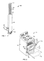
FIG. 1 is a perspective view of a hinge; -
FIG. 2 is a perspective view of an oven with which one or more hinges according toFIG 1 can be used; -
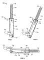
FIG. 3 is a cutaway view of a hinge showing various internal features thereof in a first position; -
FIG. 4 is a further cutaway view of the hinge ofFIG. 3 in a second position; -
FIG. 5 is a further cutaway view of the hinge ofFIG. 3 in a third position; -
FIG. 6 is a graph showing the levels of various torques provided by the hinge throughout a range of motion thereof; -
FIG. 7 is a cutaway view of an alternative hinge showing various internal features thereof in a first position; -
FIG. 8 is a further cutaway view of the hinge ofFIG. 7 in a second position; and -
FIG. 9 is a further cutaway view of the hinge ofFIG. 3 in a third position. - Referring to
FIGS. 1-9 ,reference numeral 10 generally designates a hinge for rotatably coupling a door 12 of anappliance 14 with abody 16 thereof. Hinge 10 includes aninput arm 18 affixable with thebody 16 and ahousing 20 affixable within the door 12 and coupled with the input arm so as to be rotatable through a range of motion 22 (FIG. 6 ) between a first position (for example, housing 20c inFIG. 3 ) and a second position (for example, housing 20o inFIG. 5 ). Aspring 24 is operably engaged between thehousing 20 and theinput arm 18 to apply a balancing torque to thehousing 20 relative to theinput arm 18. Afirst magnet 26 is fixed relative to thehousing 20, and asecond magnet 28 is movably received within thehousing 20 and is operatively coupled with theinput arm 18 so as to be positioned adjacent thefirst magnet 26 when thehousing 20 is in the first position and moved away from thefirst magnet 26 by rotation of thehousing 20 with respect to theinput 18 arm from the first position toward the second position. A mutual attraction between the first andsecond magnets housing 20 relative to theinput arm 18 when thehousing 20 is within about 25 degrees from the first position. - As shown in
FIG. 2 ,appliance 14 can be in the form of an oven or another similar appliance wherein a door 12 is mounted to thebody 16 of the appliance to cover anopening 32 along avertical face 34 of theappliance 14, and more particularly, one in which one or more hinges 10 rotatably couple door 12 to thebody 16 at a location adjacent alower edge 36 of theopening 32. In such an arrangement thehinges 10 provide for rotation of door 12 about ahorizontal axis 38 such that thedoor 10 opens in a vertical direction, downward and away from theopening 32. In anappliance 14 with a door 12 positioned for such downwardly rotating opening, it may be desired to provide ahinge 10 that is capable of balancing against the weight of a partially opened door through a range of possible positions of door 12 such that a user may open door 12 to a desired, partially-open position that thehinge 10 will maintain. - Further, additional functionality may be desired in which the
hinge 10 can facilitate complete and secure closing of a door 12 over anopening 32 of anappliance 14. This functionality can help to fully close door 12 when a user, for example, brings the door 12 to within a predetermined range proximate to the fully closed position (as indicated by door 12c inFIG. 2 ).Further hinge 10 can be configured to provide an additional force to help maintain the door 12 in a fully closed position againstbody 16. This force may supplement the force of thespring 24, which may be low or zero in the instance of a fully closed door 12c. Both the balancing force and the closing force may be referred to as a balancing torque and a closing torque, as the forces related thereto are applied aboutaxis 38. Aspects ofhinge 10 that provide the balancing torque and closing torque are discussed further herein. -
FIGS. 3-5 show an embodiment of ahinge 10 including aspring 24 and a pair of magnets including afirst magnet 26 and asecond magnet 28. As shown aslider 40 extends axially out of anend 42 ofhousing 20opposite input arm 18.Spring 24 is positioned over and surroundingslider 40 and is captured betweenend 42 of housing andflange 44 on the opposite end ofslider 40 therefrom.Slider 40 is operatively coupled with input arm byconnector 46, which is rotatably coupled withinput arm 18 at a location spaced apart from the rotatable coupling betweeninput arm 18 andhousing 20. Accordingly, whenhousing 20 is rotated relative to input arm 18 (such as by rotation ofdoor 10, to whichhousing 20 is attached)connector 46 moves relative tohousing 20 in a direction away fromend 42, thereby movingslider 40 in theaxial direction 48, as shown inFIG. 4 , in which housing 20a has been rotated relative toinput arm 18 by approximately 25°. Such movement causes compression ofspring 24, thereby increasing the spring force proportionate to the spring coefficient thereof. The particular spring coefficient ofspring 24 may vary according to the geometry ofhinge 10, including the amount of compression imparted onspring 24 by rotation ofhousing 20 relative toinput arm 18, as well as the weight of door 12 such thatspring 24 applies the desired balancing torque about axis 38 (which may also include an allowance for internal friction among components). This operation is reversed during closing of door 12. - As further shown in
FIGS. 3-5 , each offirst magnet 26 andsecond magnet 28 are positioned within achamber 50, which is positioned within and connected tohousing 20.First magnet 26 is fixed withinchamber 50, andsecond magnet 28 is slidably received withinchamber 50 so as to be moveable toward and away fromfirst magnet 26. Abar 52 is rigidly connected tosecond magnet 28 andbar 52 is coupled withinput arm 18 bylink 54.Link 54 is rotatably coupled withbar 52 at an end thereof oppositesecond magnet 28 and is further rotatably coupled with input arm at a location remote fromaxis 38. By this arrangement, rotation ofhousing 20 relative toinput arm 18 causessecond magnet 28 to move away fromfirst magnet 26. In the example shown inFIGS. 3-5 , link 54 is rotatably coupled withinput arm 18 at a location farther fromaxis 38 than the location of rotatable coupling ofconnector 46 withinput arm 18, which causessecond magnet 28 to move through a distance greater thanslider 40 for a given rotation ofhousing 20 relative to inputarm 18. -
First magnet 26 andsecond magnet 28 are arranged so as to be mutually attracted to each other. As with magnets in general, the amount of mutual attraction betweenfirst magnet 26 andsecond magnet 28 depends on the distance therebetween, as well as the size and magnetic field strength of the magnets. In an examplefirst magnet 26 andsecond magnet 28 can each have a magnetic field strength between about 1 T and 1.5 T. As shown inFIG. 3 , thedistance 56 between first magnet andsecond magnet 28 is zero whenhousing 20c is in the position that corresponds to a fully closed door 12c (FIG. 2 ). Accordingly, in such a position, the mutual attraction betweenfirst magnet 26 andsecond magnet 28 is greatest in such a positioning ofhousing 20c relative to inputarm 18. This mutual attraction resists movement of firstsecond magnet 28 relative tofirst magnet 28 and, accordingly, rotational movement ofhousing 20c relative to inputarm 18. This additional force helps maintain door 12c in the closed position relative tobody 16, as described above, through the application of a closing torque aboutaxis 38. In an embodiment, the closing torque applied whenhousing 20c is in the closed state can be between about 60 N-m and 80 N-m. In a more particular embodiment, the closing torque in associated with the closed position ofhousing 20c can be about 70 N-m. - As shown in
FIGS. 3 and 4 , the above-describe coupling ofslider 40 andsecond magnet 28 withinput arm 18 is such thatsecond magnet 28 moves away from first magnet simultaneously with compression ofspring 24 by rotation ofhousing 20 relative to inputarm 18. Such movement ofhousing 20 is implemented by, for example, an opening movement of door 12 relative tobody 16 of an associatedappliance 14, such as by downward rotation thereof. During initial rotation ofhousing 20,first magnet 26 andsecond magnet 28 move away from each other but remain proximate to each other such that the mutual attraction therebetween remains appreciably present. In an example, the strength of first andsecond magnets second magnet 28 relative to the rotation ofhousing 20 can be such that the mutual attraction betweenfirst magnet 26 andsecond magnet 28 remains appreciably present through an auto-closing range of motion. As illustrated inFIG. 4 , such an auto-closing range of motion can be a rotational range of motion Θa ofhousing 20a relative to the closed position of housing 20c (FIG. 3 ). In an embodiment, the auto-closing range of motion Θa can be through a rotation of between about 15° and 45°, and in a particular embodiment, a rotation of about 25°. Such a range can also apply to movement of door 12 relative tobody 16, as depicted by the position of door 12a inFIG. 2 , which has been rotated to the end of auto-closing range Θa. Such a range may correspond to adistance 56 betweenfirst magnet 26 andsecond magnet 28 of between 4 mm and 5 mm and in one embodiment about 4.13 mm. - The appreciable mutual attraction between first and
second magnets axis 38, acting throughhousing 20 to urge door 12 toward the closed position (door 12c inFIG. 2 ). In an example, the auto-closing torque can be such that, if door 12 is moved from a position farther open than auto-closing range Θa (for example, within balancing range Θb, as shown in connection with door 12b inFIG. 2 and withhousing 20b inFIG. 5 ) into auto-closing range Θa and then let go, the auto-closing torque will act on door 12a to bring it to the closed position of door 12c (FIG. 2 ). In a further example, if door 12c is moved from out of the closed position to a position within auto-closing range Θa and then released, the auto-closing torque will move door 12a back to the closed door 12c position. - Once
housing 20 is moved outside of the auto closing range Θa toward theopen hinge 18o position, shown inFIG. 5 by movement of door 12 toward the open door 12o position (FIG. 2 ),first magnet 26 andsecond magnet 28 will have been moved far enough apart such that the mutual attraction therebetween is no longer sufficient to produce an auto-closing torque. For example, a mutual attraction betweenfirst magnet 26 andsecond magnet 28 may be present, but the torque produced aboutaxis 38 may not be sufficient to overcome the inertia of door 12b when positioned within the balancing range Θb between the auto-closing range Θa and the open door 12o position. Such a force may also be insufficient to produce a torque that is sufficient to overcome the resting friction between the various components ofhinge 10. As such, whenhousing 20b is in the balancing range Θb, a selected position thereof may be maintained by the balancing torque applied by thespring 24 due to the increased compression thereof. When in the fully open door 12o position, such positioning of door 12o andhousing 200 may be maintained by the mechanical limits ofhinge 10 or by the geometry ofappliance 14 or by a combination thereof with the balancing torque provided byspring 24. - As shown in the graph of
FIG. 6 , thepeak 56 of the auto-closing torque, represented byline 58 corresponds to the position of door 12c andhousing 20c when closed and in whichsecond magnet 28 contactsfirst magnet 26. With movement of door 12a away from the closed position and toward the open door 12o position, the mutual attraction betweenfirst magnet 26 andsecond magnet 28 decreases logarithmically with the corresponding movement ofsecond magnet 28 away fromfirst magnet 26. During this movement, movement ofslider 40 begins to compressspring 24 such that the balancing torque, represented byline 60, which is combined withauto closing torque 58 to achieve atotal torque 62. - The transition Θt from the auto-closing range Θa to the balancing range Θb occurs when the torque provided by the attraction between
first magnet 26 andsecond magnet 28 reaches aminimum level 64. In an example, such aminimum level 64 may be such that thetotal torque 62 is only sufficient to balance against the increasing opposite torque provided by the weight of door 12 as the moment arm thereof increases in horizontal length. Continued compression ofspring 24 results in an increase in balancingtorque 60 that corresponds to the increasing torque applied aboutaxis 38 by door 12b by selection of aspring 24 with a coefficient that corresponds to the movement ofslider 40 achieved by the geometry ofhinge 10. The combination of the torques provided by the balancingtorque 60 and the auto-closingtorque 58, thusly, provides the movement characteristics for door 12 described above. In an embodiment, the auto-closing torque at a point 66 where door 12 is at the transition angle Θt can be about 3 N-m or less and, in one embodiment can be about 2.7 N-m. Continued movement of door 12b within the balancing position can further decrease the auto-closing torque below the level at the transition angle Θt. -
FIGS. 7-9 show another embodiment of ahinge 110 that can carry out the auto-closing and balancing functionality described above with respect toFIGS. 1-6 . As with the previous embodiment, hinge 110 includes including aspring 124 and a pair of magnets including afirst magnet 126 and asecond magnet 128.Slider 140 extends axially out of end 142 of housing 118opposite input arm 120.Spring 124 is positioned over and surroundingslider 140 and is captured between end 142 of housing andflange 144 on the opposite end ofslider 140 therefrom.Slider 140 is operatively coupled withinput arm 120 byconnector 146, which is rotatably coupled withinput arm 120 at a location spaced apart from the rotatable coupling betweeninput arm 120 and housing 118. Accordingly, when housing 118 is rotated relative to input arm 120 (such as by rotation ofdoor 10, to which housing 118 may be attached in a manner similar to that ofhousing 20, described above)connector 146 moves relative to housing 118 in a direction away from end 142, thereby movingslider 140 in theaxial direction 148, as shown inFIG. 8 , in which housing 118a has been rotated relative to inputarm 120 by approximately 25°. Such movement causes compression ofspring 124, thereby increasing the spring force proportionate to the spring coefficient thereof. The particular spring coefficient ofspring 124 may vary according to the geometry ofhinge 110, including the amount of compression imparted onspring 124 by rotation of housing 118 relative to inputarm 120, as well as the weight of door 112 such thatspring 124 applies the desired balancing torque aboutaxis 138 in a manner similar to that described above, including with reference toFIG. 6 . This operation is reversed during closing of door 12. - As further shown in
FIGS. 7-9 ,first magnet 126 is fixed within housing 118, andsecond magnet 128 is fixed withslider 140 so as to be moveable withslider 140 within housing 118 and moveable toward and away fromfirst magnet 126. By this arrangement, rotation of housing 118 relative to inputarm 120 causessecond magnet 128 to move away fromfirst magnet 126 by the same distance and the compression ofspring 124. As shown inFIG. 7 , thedistance 156 betweenfirst magnet 126 andsecond magnet 128 is zero when housing 118c is in the position that corresponds to a fully closed door 12c (FIG. 2 ) such that the force provided by the mechanism (i.e. the closing force) is provided by both the spring and the magnets. Initially during opening of door 12a corresponding to the movement of housing 118a within auto-closing range Θs, shown inFIG. 8 , thefirst magnet 126 andsecond magnet 128 continue to contribute an appreciable auto-closing torque, as described above with respect toFIG 6 (and with quantities that can be the same as or similar to those described above with respect to hinge 10 inFIGS. 3-5 ). As also described above, movement of door 12b to within balancing range Θb results in the auto-closing torque being lower than that needed to implement auto-closing of door 12, at whichpoint spring 124 and the torque aboutaxis 138 provided thereby continues to balance against the weight torque of door 12, thereby maintaining a selected position of door within balancing range Θb up to the fully open housing 118o position (as shown inFIG. 9 ).
Claims (15)
- A hinge (10, 110) for rotatably coupling an appliance door (12) with an appliance body (16), comprising:an input arm (18) affixable with the body (16);a housing (20, 118) affixable within the door (12) and coupled with the input arm (18) so as to be rotatable through a range of motion between a first position and a second position;a spring (24, 124) operably engaged between the housing and the input arm to apply a balancing torque (60) to the housing arm relative to the input arm (18);a first magnet (26, 126) fixed relative to the housing (20, 118); anda second magnet (28, 128) movably received within the housing and operatively coupled with the input arm (18, 120) so as to be positioned adjacent the first magnet (26, 126) when the housing (20, 118)is in the first position and moved away from the first magnet by rotation of the housing with respect to the input arm from the first position toward the second position;wherein a mutual attraction between the first and second magnets applies a closing torque (58) to the housing relative to the input arm when the housing is within about 25 degrees from the first position.
- The hinge of claim 1, wherein:the balancing force increases with rotation of the input arm (18) from the first position toward the second position; andthe closing torque (58) decreases with rotation of the input arm from the first position toward the second position, the closing torque falling below and effective threshold level with rotation of the housing (20, 118) by more than 25 degrees from the first position.
- The hinge of claim 2, wherein the effective threshold level is between 2 N-m and 3 N-m.
- The hinge of claim 1, wherein:a peak closing torque is applied on the input arm (18) by the mutual attraction between the magnets (26, 126, 28, 128) when the input arm is in the first position; anda peak balancing torque is applied on the input arm by the spring when the input arm is in the second position.
- The hinge of claim 4, wherein the peak closing torque is at least three times a peak balancing torque.
- The hinge of claim 1, further including a slider (40, 140) extending along a first axis through an opening in an end (42, 142) of the housing (20, 118), the slider at least partially operatively coupling the spring (24, 124) with the housing;
wherein:the housing extending along the first axis; andthe spring (24, 124) surrounds the slider (40, 140) and is captured between a portion of the slider and a portion of the housing such that compression of the spring between the portion of the slider and the portion of the housing applies the balancing torque (60). - The hinge of claim 1, wherein:the first magnet (26, 126) is fixedly coupled to the housing adjacent the first end thereof, the slider (40, 140) passing through an opening in the first magnet; andthe second magnet (28, 128) is fixedly coupled at a second end thereof with the slider.
- The hinge of claim 1, further including:a chamber (50) fixed within the housing (20), the first magnet (26) being fixed within the chamber and the second magnet (28) being slidably received within the chamber;a bar (52) rigidly attached to the second magnet (28); anda link (54) operably connecting the input arm (18) to the second magnet (28).
- The hinge of claim 1, further including a connector (46, 146) rotatably coupled with the input arm (18) and at least partially operably engaging the input arm with the spring (24, 124).
- An appliance (14), comprising:a hinge (10, 110) according to claim 1;a body (16) defining an opening with a lower edge, the input arm (18) of the hinge coupled with the body; anda door (12) positionable over the opening of the body, the housing of the hinge coupled with the door such that the door is rotatable adjacent the lower edge of the opening and rotates away from the opening in a vertical direction between a closed position, corresponding to the first position of the housing, and an open position, corresponding to the second position of the housing;wherein the balancing torque (60) applied by the spring (24, 124) to the housing arm relative to the input arm substantially matches a weight torque of the door about the hinge.
- The appliance of claim 10, wherein the closing torque (58) is operable to apply a closing torque to the input arm relative to the housing to urge to door (12) toward the closed position when the door is within 25 degrees of the closed position.
- The hinge of claim 1, wherein the balancing torque (60) increases from about 0 N-m when the housing is in the first position to about 30 N-m when the housing is in the second position.
- The hinge of claim 1, wherein the closing torque decreases from about 70 N-m when the housing is in the first position to less than about 3 N-m when the housing is about 25 degrees from the first position.
- The hinge of claim 1, wherein:a distance (56) between the first magnet (26, 126) and the second magnet (28, 128) is zero when the housing is in the first position; andthe distance (56) between the first magnet and the second magnet is between 7 mm and 8 mm when the housing is about 25 degrees from the first position.
- The hinge of claim 14, wherein the distance (56) between the first magnet and the second magnet is about 30 mm when the housing is in the second position.
Applications Claiming Priority (1)
| Application Number | Priority Date | Filing Date | Title |
|---|---|---|---|
| US14/294,183 US9181737B1 (en) | 2014-06-03 | 2014-06-03 | Oven door opening magnetic hinge |
Publications (2)
| Publication Number | Publication Date |
|---|---|
| EP2952666A1 true EP2952666A1 (en) | 2015-12-09 |
| EP2952666B1 EP2952666B1 (en) | 2018-06-20 |
Family
ID=53175353
Family Applications (1)
| Application Number | Title | Priority Date | Filing Date |
|---|---|---|---|
| EP15167649.1A Not-in-force EP2952666B1 (en) | 2014-06-03 | 2015-05-13 | Magnetic hinge for an oven door |
Country Status (2)
| Country | Link |
|---|---|
| US (2) | US9181737B1 (en) |
| EP (1) | EP2952666B1 (en) |
Cited By (1)
| Publication number | Priority date | Publication date | Assignee | Title |
|---|---|---|---|---|
| CN111005634A (en) * | 2019-12-30 | 2020-04-14 | 广东永丰智威电气有限公司 | Spring hinge device of pull-down type turning plate for oven |
Families Citing this family (18)
| Publication number | Priority date | Publication date | Assignee | Title |
|---|---|---|---|---|
| US9316036B2 (en) * | 2013-05-23 | 2016-04-19 | Mansfield Engineered Components, Inc. | Appliance hinge counterbalance assembly with snubber |
| CN105593449A (en) * | 2013-09-02 | 2016-05-18 | 深圳市金合联投资有限公司 | Hinge |
| US9631819B2 (en) * | 2013-09-18 | 2017-04-25 | Bsh Home Appliances Corporation | Home cooking appliance with a side swing oven door having a friction hinge |
| KR102464262B1 (en) * | 2016-04-15 | 2022-11-09 | 삼성전자주식회사 | Household electrical appliances having with door key linked to rotation movement of door |
| US10301858B2 (en) * | 2016-06-14 | 2019-05-28 | Microsoft Technology Licensing, Llc | Hinge mechanism |
| US9840861B1 (en) * | 2016-06-14 | 2017-12-12 | Microsoft Technology Licensing, Llc | Hinged device with snap open lock |
| US10501973B2 (en) | 2016-06-14 | 2019-12-10 | Microsoft Technology Licensing, Llc | Hinge with free-stop function |
| US10061359B2 (en) | 2016-07-28 | 2018-08-28 | Microsoft Technology Licensing, Llc | Hinged device with living hinge |
| CN106088892B (en) * | 2016-08-16 | 2018-04-03 | 佛山市顺德区诺维电器有限公司 | A kind of ultra-thin baking box door connection structure |
| US10704311B1 (en) | 2017-02-06 | 2020-07-07 | Mansfield Engineered Components, Inc. | Appliance lid hinge |
| GB2561572B (en) * | 2017-04-18 | 2021-05-26 | Galeid Ltd | Door closer |
| WO2019061023A1 (en) * | 2017-09-26 | 2019-04-04 | 佛山市伟仕达电器实业有限公司 | Door hinge and electric oven |
| CN107630614A (en) * | 2017-09-26 | 2018-01-26 | 佛山市伟仕达电器实业有限公司 | A kind of box door hinges and electric oven |
| US10837695B2 (en) * | 2017-12-04 | 2020-11-17 | Electrolux Home Products, Inc. | Refrigerator assembly |
| ES2911628T3 (en) * | 2017-12-18 | 2022-05-20 | C M I Cerniere Mecc Industriali Srl | Hinge device with end-stop damping |
| US11906170B2 (en) | 2019-04-29 | 2024-02-20 | Winston Industries, Llc | Magnetic positioning hinge for horizontal door assembly |
| CN110313844B (en) * | 2019-08-21 | 2024-07-16 | 无锡市惠昌烧烤炉科技有限公司 | Barbecue oven damping hinge |
| CN112727281A (en) * | 2021-02-23 | 2021-04-30 | 珠海格力电器股份有限公司 | Door body assembly for cooking equipment and cooking equipment |
Citations (1)
| Publication number | Priority date | Publication date | Assignee | Title |
|---|---|---|---|---|
| US20100251521A1 (en) * | 2009-04-01 | 2010-10-07 | Electrolux Home Products, Inc. | Door hinge assembly |
Family Cites Families (31)
| Publication number | Priority date | Publication date | Assignee | Title |
|---|---|---|---|---|
| US3016563A (en) | 1959-03-04 | 1962-01-16 | Jong George Edward De | Combined hinge and catch |
| US3388418A (en) | 1965-07-27 | 1968-06-18 | Monarch Tool & Machinery Compa | Magnetic hinge |
| US3562850A (en) | 1968-08-13 | 1971-02-16 | Eliason Refrigerator Co | Magnetic door holder |
| DE3224300C2 (en) * | 1982-06-29 | 1984-11-29 | Geze Gmbh, 7250 Leonberg | Door closer with adjustable closing force |
| US4506407A (en) * | 1983-07-18 | 1985-03-26 | Schlage Lock Company | Releasable hold-open device for a door closer |
| US4561130A (en) | 1984-06-05 | 1985-12-31 | Dewey Bumgardner | Toilet seat cover safety latch |
| US4658473A (en) * | 1985-12-23 | 1987-04-21 | Truth Incorporated | Concealed freezer hinge |
| US5120030A (en) * | 1991-05-28 | 1992-06-09 | General Motors Corporation | Magnet assisted liftgate strut |
| US5592780A (en) * | 1995-06-07 | 1997-01-14 | Checkovich; Peter | Door position controlling apparatus |
| US6167589B1 (en) | 1999-03-25 | 2001-01-02 | Daren J. Luedtke | Control mechanism including a permanent magnet system |
| ES2320086T3 (en) * | 2000-05-12 | 2009-05-19 | Antonio Giovannetti | SPRING-DRIVED DEVICE FOR MOVEMENT OF A DOOR, WITH AN ADJUSTABLE SPRING ARM ARM. |
| US20030172920A1 (en) * | 2001-02-15 | 2003-09-18 | Lina Gronbach | Hinge for a stove door |
| US7150071B2 (en) * | 2003-03-05 | 2006-12-19 | Mansfield Assemblies Co. | Breakaway hinge system for appliance door |
| US7275283B2 (en) * | 2004-05-03 | 2007-10-02 | Keystone Friction Hinge Co. | Appliance hinge |
| WO2007028400A1 (en) * | 2005-09-02 | 2007-03-15 | Pauli + Sohn Gmbh Metallwaren | Door hinge, in particular shower door hinge |
| US20070209654A1 (en) * | 2006-03-07 | 2007-09-13 | Ching-Hsiang Wang | Hinge device of a steam oven door |
| ITBO20060308A1 (en) * | 2006-04-21 | 2007-10-22 | Nuova Star Spa | HINGE FOR DOORS OR DOORS |
| ITBO20070110A1 (en) * | 2007-02-22 | 2008-08-23 | Nuova Star Spa | HINGE FOR DOORS OR DOORS. |
| ES2537543T3 (en) * | 2007-05-18 | 2015-06-09 | Faringosi-Hinges S.R.L. | Door hinge |
| JP5608164B2 (en) | 2007-08-06 | 2014-10-15 | クリストファー スチュアート,マイケル | Hinge |
| DE202007012603U1 (en) * | 2007-09-07 | 2009-01-22 | Hettich-Oni Gmbh & Co. Kg | Door hinge of a household appliance |
| US8132292B2 (en) | 2008-02-11 | 2012-03-13 | Sony Ericsson Mobile Communications Ab | Hinge mechanism for a wireless communication device |
| US20090235713A1 (en) * | 2008-03-24 | 2009-09-24 | Hirotec America, Inc. | Magnetically actuated roller head |
| CN101684840B (en) | 2008-09-25 | 2012-10-10 | 鸿富锦精密工业(深圳)有限公司 | Magnetic hinge structure |
| ATE521776T1 (en) * | 2009-02-13 | 2011-09-15 | Electrolux Home Prod Corp | OVEN DOOR OPENING AND CLOSING DEVICE |
| GB0907954D0 (en) | 2009-05-08 | 2009-06-24 | Fireco Ltd | Appararatus for controlling the movement of a closure |
| GB0916768D0 (en) | 2009-09-24 | 2009-11-04 | Ingersoll Rand Security Techno | A door closer |
| US20110146655A1 (en) * | 2009-12-21 | 2011-06-23 | Whirlpool Corporation | Hydraulic hinge for freestanding appliance |
| DE202010005948U1 (en) * | 2010-04-17 | 2010-07-08 | Hoffmann, Peter | Pneumatic door buffer and door closer as well as mounting device |
| WO2012168748A1 (en) * | 2011-06-08 | 2012-12-13 | Faringosi Hinges S.R.L. | Hinges provided with elastic means and dampener |
| US8517448B2 (en) | 2011-08-30 | 2013-08-27 | GM Global Technology Operations LLC | Decklid damper for a vehicle |
-
2014
- 2014-06-03 US US14/294,183 patent/US9181737B1/en active Active
-
2015
- 2015-05-13 EP EP15167649.1A patent/EP2952666B1/en not_active Not-in-force
- 2015-10-27 US US14/923,562 patent/US9840862B2/en not_active Expired - Fee Related
Patent Citations (1)
| Publication number | Priority date | Publication date | Assignee | Title |
|---|---|---|---|---|
| US20100251521A1 (en) * | 2009-04-01 | 2010-10-07 | Electrolux Home Products, Inc. | Door hinge assembly |
Cited By (2)
| Publication number | Priority date | Publication date | Assignee | Title |
|---|---|---|---|---|
| CN111005634A (en) * | 2019-12-30 | 2020-04-14 | 广东永丰智威电气有限公司 | Spring hinge device of pull-down type turning plate for oven |
| CN111005634B (en) * | 2019-12-30 | 2021-06-01 | 广东永丰智威电气有限公司 | Spring hinge device of pull-down type turning plate for oven |
Also Published As
| Publication number | Publication date |
|---|---|
| EP2952666B1 (en) | 2018-06-20 |
| US20160047153A1 (en) | 2016-02-18 |
| US9181737B1 (en) | 2015-11-10 |
| US20150345194A1 (en) | 2015-12-03 |
| US9840862B2 (en) | 2017-12-12 |
Similar Documents
| Publication | Publication Date | Title |
|---|---|---|
| EP2952666B1 (en) | Magnetic hinge for an oven door | |
| CN106460434B (en) | Hinge | |
| US8938912B2 (en) | Door actuator | |
| CN105960500B (en) | Bearing arrangement for door | |
| WO2020112058A3 (en) | Furniture hinge for upward-opening cabinet doors | |
| EP3074582B1 (en) | Hinge having hinge cup | |
| EP2664737A2 (en) | A door hinge | |
| US9879462B2 (en) | Hinge assemblies | |
| US10253541B2 (en) | Hinge assembly | |
| WO2017030904A1 (en) | Dual direction door closer | |
| US20180073291A1 (en) | Dampened hinge | |
| EP3945193B1 (en) | Single-pin hinge for doors and/or panels of furniture or furnishing items | |
| JP6920598B2 (en) | Cooker | |
| CN110234830A (en) | Improved damper assembly | |
| US20180209196A1 (en) | Improvements in Hinge Assemblies | |
| KR20200063141A (en) | Manipulators for access members, access members including manipulators, systems and methods | |
| KR101204349B1 (en) | Hinge device for oven | |
| RU2674608C2 (en) | Hinge for furniture or household appliances | |
| WO2016143903A1 (en) | Vehicle handle device | |
| EP3179023B1 (en) | A hinge mechanism | |
| CN106460436B (en) | Hinges for furniture or household appliances | |
| CN115023572B (en) | Oven door hinges | |
| CN206646939U (en) | Anti-mistake device and doors and windows equipped with the anti-mistake device | |
| WO2017162662A1 (en) | Access member manipulator and system |
Legal Events
| Date | Code | Title | Description |
|---|---|---|---|
| PUAI | Public reference made under article 153(3) epc to a published international application that has entered the european phase |
Free format text: ORIGINAL CODE: 0009012 |
|
| AK | Designated contracting states |
Kind code of ref document: A1 Designated state(s): AL AT BE BG CH CY CZ DE DK EE ES FI FR GB GR HR HU IE IS IT LI LT LU LV MC MK MT NL NO PL PT RO RS SE SI SK SM TR |
|
| AX | Request for extension of the european patent |
Extension state: BA ME |
|
| 17P | Request for examination filed |
Effective date: 20160608 |
|
| RBV | Designated contracting states (corrected) |
Designated state(s): AL AT BE BG CH CY CZ DE DK EE ES FI FR GB GR HR HU IE IS IT LI LT LU LV MC MK MT NL NO PL PT RO RS SE SI SK SM TR |
|
| GRAP | Despatch of communication of intention to grant a patent |
Free format text: ORIGINAL CODE: EPIDOSNIGR1 |
|
| STAA | Information on the status of an ep patent application or granted ep patent |
Free format text: STATUS: GRANT OF PATENT IS INTENDED |
|
| INTG | Intention to grant announced |
Effective date: 20180207 |
|
| GRAS | Grant fee paid |
Free format text: ORIGINAL CODE: EPIDOSNIGR3 |
|
| GRAA | (expected) grant |
Free format text: ORIGINAL CODE: 0009210 |
|
| STAA | Information on the status of an ep patent application or granted ep patent |
Free format text: STATUS: THE PATENT HAS BEEN GRANTED |
|
| AK | Designated contracting states |
Kind code of ref document: B1 Designated state(s): AL AT BE BG CH CY CZ DE DK EE ES FI FR GB GR HR HU IE IS IT LI LT LU LV MC MK MT NL NO PL PT RO RS SE SI SK SM TR |
|
| REG | Reference to a national code |
Ref country code: GB Ref legal event code: FG4D |
|
| REG | Reference to a national code |
Ref country code: IE Ref legal event code: FG4D |
|
| REG | Reference to a national code |
Ref country code: AT Ref legal event code: REF Ref document number: 1010718 Country of ref document: AT Kind code of ref document: T Effective date: 20180715 |
|
| REG | Reference to a national code |
Ref country code: DE Ref legal event code: R096 Ref document number: 602015012440 Country of ref document: DE |
|
| REG | Reference to a national code |
Ref country code: NL Ref legal event code: MP Effective date: 20180620 |
|
| PG25 | Lapsed in a contracting state [announced via postgrant information from national office to epo] |
Ref country code: SE Free format text: LAPSE BECAUSE OF FAILURE TO SUBMIT A TRANSLATION OF THE DESCRIPTION OR TO PAY THE FEE WITHIN THE PRESCRIBED TIME-LIMIT Effective date: 20180620 Ref country code: BG Free format text: LAPSE BECAUSE OF FAILURE TO SUBMIT A TRANSLATION OF THE DESCRIPTION OR TO PAY THE FEE WITHIN THE PRESCRIBED TIME-LIMIT Effective date: 20180920 Ref country code: NO Free format text: LAPSE BECAUSE OF FAILURE TO SUBMIT A TRANSLATION OF THE DESCRIPTION OR TO PAY THE FEE WITHIN THE PRESCRIBED TIME-LIMIT Effective date: 20180920 Ref country code: FI Free format text: LAPSE BECAUSE OF FAILURE TO SUBMIT A TRANSLATION OF THE DESCRIPTION OR TO PAY THE FEE WITHIN THE PRESCRIBED TIME-LIMIT Effective date: 20180620 Ref country code: LT Free format text: LAPSE BECAUSE OF FAILURE TO SUBMIT A TRANSLATION OF THE DESCRIPTION OR TO PAY THE FEE WITHIN THE PRESCRIBED TIME-LIMIT Effective date: 20180620 |
|
| REG | Reference to a national code |
Ref country code: LT Ref legal event code: MG4D |
|
| PG25 | Lapsed in a contracting state [announced via postgrant information from national office to epo] |
Ref country code: GR Free format text: LAPSE BECAUSE OF FAILURE TO SUBMIT A TRANSLATION OF THE DESCRIPTION OR TO PAY THE FEE WITHIN THE PRESCRIBED TIME-LIMIT Effective date: 20180921 Ref country code: HR Free format text: LAPSE BECAUSE OF FAILURE TO SUBMIT A TRANSLATION OF THE DESCRIPTION OR TO PAY THE FEE WITHIN THE PRESCRIBED TIME-LIMIT Effective date: 20180620 Ref country code: LV Free format text: LAPSE BECAUSE OF FAILURE TO SUBMIT A TRANSLATION OF THE DESCRIPTION OR TO PAY THE FEE WITHIN THE PRESCRIBED TIME-LIMIT Effective date: 20180620 Ref country code: RS Free format text: LAPSE BECAUSE OF FAILURE TO SUBMIT A TRANSLATION OF THE DESCRIPTION OR TO PAY THE FEE WITHIN THE PRESCRIBED TIME-LIMIT Effective date: 20180620 |
|
| REG | Reference to a national code |
Ref country code: AT Ref legal event code: MK05 Ref document number: 1010718 Country of ref document: AT Kind code of ref document: T Effective date: 20180620 |
|
| PG25 | Lapsed in a contracting state [announced via postgrant information from national office to epo] |
Ref country code: NL Free format text: LAPSE BECAUSE OF FAILURE TO SUBMIT A TRANSLATION OF THE DESCRIPTION OR TO PAY THE FEE WITHIN THE PRESCRIBED TIME-LIMIT Effective date: 20180620 |
|
| PG25 | Lapsed in a contracting state [announced via postgrant information from national office to epo] |
Ref country code: RO Free format text: LAPSE BECAUSE OF FAILURE TO SUBMIT A TRANSLATION OF THE DESCRIPTION OR TO PAY THE FEE WITHIN THE PRESCRIBED TIME-LIMIT Effective date: 20180620 Ref country code: CZ Free format text: LAPSE BECAUSE OF FAILURE TO SUBMIT A TRANSLATION OF THE DESCRIPTION OR TO PAY THE FEE WITHIN THE PRESCRIBED TIME-LIMIT Effective date: 20180620 Ref country code: PL Free format text: LAPSE BECAUSE OF FAILURE TO SUBMIT A TRANSLATION OF THE DESCRIPTION OR TO PAY THE FEE WITHIN THE PRESCRIBED TIME-LIMIT Effective date: 20180620 Ref country code: AT Free format text: LAPSE BECAUSE OF FAILURE TO SUBMIT A TRANSLATION OF THE DESCRIPTION OR TO PAY THE FEE WITHIN THE PRESCRIBED TIME-LIMIT Effective date: 20180620 Ref country code: EE Free format text: LAPSE BECAUSE OF FAILURE TO SUBMIT A TRANSLATION OF THE DESCRIPTION OR TO PAY THE FEE WITHIN THE PRESCRIBED TIME-LIMIT Effective date: 20180620 Ref country code: IS Free format text: LAPSE BECAUSE OF FAILURE TO SUBMIT A TRANSLATION OF THE DESCRIPTION OR TO PAY THE FEE WITHIN THE PRESCRIBED TIME-LIMIT Effective date: 20181020 Ref country code: SK Free format text: LAPSE BECAUSE OF FAILURE TO SUBMIT A TRANSLATION OF THE DESCRIPTION OR TO PAY THE FEE WITHIN THE PRESCRIBED TIME-LIMIT Effective date: 20180620 |
|
| PG25 | Lapsed in a contracting state [announced via postgrant information from national office to epo] |
Ref country code: SM Free format text: LAPSE BECAUSE OF FAILURE TO SUBMIT A TRANSLATION OF THE DESCRIPTION OR TO PAY THE FEE WITHIN THE PRESCRIBED TIME-LIMIT Effective date: 20180620 Ref country code: ES Free format text: LAPSE BECAUSE OF FAILURE TO SUBMIT A TRANSLATION OF THE DESCRIPTION OR TO PAY THE FEE WITHIN THE PRESCRIBED TIME-LIMIT Effective date: 20180620 |
|
| REG | Reference to a national code |
Ref country code: DE Ref legal event code: R097 Ref document number: 602015012440 Country of ref document: DE |
|
| PLBE | No opposition filed within time limit |
Free format text: ORIGINAL CODE: 0009261 |
|
| STAA | Information on the status of an ep patent application or granted ep patent |
Free format text: STATUS: NO OPPOSITION FILED WITHIN TIME LIMIT |
|
| 26N | No opposition filed |
Effective date: 20190321 |
|
| PG25 | Lapsed in a contracting state [announced via postgrant information from national office to epo] |
Ref country code: DK Free format text: LAPSE BECAUSE OF FAILURE TO SUBMIT A TRANSLATION OF THE DESCRIPTION OR TO PAY THE FEE WITHIN THE PRESCRIBED TIME-LIMIT Effective date: 20180620 |
|
| PG25 | Lapsed in a contracting state [announced via postgrant information from national office to epo] |
Ref country code: SI Free format text: LAPSE BECAUSE OF FAILURE TO SUBMIT A TRANSLATION OF THE DESCRIPTION OR TO PAY THE FEE WITHIN THE PRESCRIBED TIME-LIMIT Effective date: 20180620 |
|
| PG25 | Lapsed in a contracting state [announced via postgrant information from national office to epo] |
Ref country code: AL Free format text: LAPSE BECAUSE OF FAILURE TO SUBMIT A TRANSLATION OF THE DESCRIPTION OR TO PAY THE FEE WITHIN THE PRESCRIBED TIME-LIMIT Effective date: 20180620 |
|
| REG | Reference to a national code |
Ref country code: CH Ref legal event code: PL |
|
| PG25 | Lapsed in a contracting state [announced via postgrant information from national office to epo] |
Ref country code: MC Free format text: LAPSE BECAUSE OF FAILURE TO SUBMIT A TRANSLATION OF THE DESCRIPTION OR TO PAY THE FEE WITHIN THE PRESCRIBED TIME-LIMIT Effective date: 20180620 Ref country code: LI Free format text: LAPSE BECAUSE OF NON-PAYMENT OF DUE FEES Effective date: 20190531 Ref country code: CH Free format text: LAPSE BECAUSE OF NON-PAYMENT OF DUE FEES Effective date: 20190531 |
|
| REG | Reference to a national code |
Ref country code: BE Ref legal event code: MM Effective date: 20190531 |
|
| PG25 | Lapsed in a contracting state [announced via postgrant information from national office to epo] |
Ref country code: LU Free format text: LAPSE BECAUSE OF NON-PAYMENT OF DUE FEES Effective date: 20190513 |
|
| PG25 | Lapsed in a contracting state [announced via postgrant information from national office to epo] |
Ref country code: TR Free format text: LAPSE BECAUSE OF FAILURE TO SUBMIT A TRANSLATION OF THE DESCRIPTION OR TO PAY THE FEE WITHIN THE PRESCRIBED TIME-LIMIT Effective date: 20180620 |
|
| PG25 | Lapsed in a contracting state [announced via postgrant information from national office to epo] |
Ref country code: IE Free format text: LAPSE BECAUSE OF NON-PAYMENT OF DUE FEES Effective date: 20190513 |
|
| PG25 | Lapsed in a contracting state [announced via postgrant information from national office to epo] |
Ref country code: BE Free format text: LAPSE BECAUSE OF NON-PAYMENT OF DUE FEES Effective date: 20190531 |
|
| PG25 | Lapsed in a contracting state [announced via postgrant information from national office to epo] |
Ref country code: PT Free format text: LAPSE BECAUSE OF FAILURE TO SUBMIT A TRANSLATION OF THE DESCRIPTION OR TO PAY THE FEE WITHIN THE PRESCRIBED TIME-LIMIT Effective date: 20181022 |
|
| PG25 | Lapsed in a contracting state [announced via postgrant information from national office to epo] |
Ref country code: CY Free format text: LAPSE BECAUSE OF FAILURE TO SUBMIT A TRANSLATION OF THE DESCRIPTION OR TO PAY THE FEE WITHIN THE PRESCRIBED TIME-LIMIT Effective date: 20180620 |
|
| PG25 | Lapsed in a contracting state [announced via postgrant information from national office to epo] |
Ref country code: HU Free format text: LAPSE BECAUSE OF FAILURE TO SUBMIT A TRANSLATION OF THE DESCRIPTION OR TO PAY THE FEE WITHIN THE PRESCRIBED TIME-LIMIT; INVALID AB INITIO Effective date: 20150513 Ref country code: MT Free format text: LAPSE BECAUSE OF FAILURE TO SUBMIT A TRANSLATION OF THE DESCRIPTION OR TO PAY THE FEE WITHIN THE PRESCRIBED TIME-LIMIT Effective date: 20180620 |
|
| PG25 | Lapsed in a contracting state [announced via postgrant information from national office to epo] |
Ref country code: MK Free format text: LAPSE BECAUSE OF FAILURE TO SUBMIT A TRANSLATION OF THE DESCRIPTION OR TO PAY THE FEE WITHIN THE PRESCRIBED TIME-LIMIT Effective date: 20180620 |
|
| PGFP | Annual fee paid to national office [announced via postgrant information from national office to epo] |
Ref country code: FR Payment date: 20230309 Year of fee payment: 9 |
|
| PGFP | Annual fee paid to national office [announced via postgrant information from national office to epo] |
Ref country code: GB Payment date: 20230323 Year of fee payment: 9 |
|
| P01 | Opt-out of the competence of the unified patent court (upc) registered |
Effective date: 20230522 |
|
| PGFP | Annual fee paid to national office [announced via postgrant information from national office to epo] |
Ref country code: IT Payment date: 20230412 Year of fee payment: 9 Ref country code: DE Payment date: 20230321 Year of fee payment: 9 |
|
| REG | Reference to a national code |
Ref country code: DE Ref legal event code: R119 Ref document number: 602015012440 Country of ref document: DE |
|
| GBPC | Gb: european patent ceased through non-payment of renewal fee |
Effective date: 20240513 |
|
| PG25 | Lapsed in a contracting state [announced via postgrant information from national office to epo] |
Ref country code: DE Free format text: LAPSE BECAUSE OF NON-PAYMENT OF DUE FEES Effective date: 20241203 |
|
| PG25 | Lapsed in a contracting state [announced via postgrant information from national office to epo] |
Ref country code: FR Free format text: LAPSE BECAUSE OF NON-PAYMENT OF DUE FEES Effective date: 20240531 |
|
| PG25 | Lapsed in a contracting state [announced via postgrant information from national office to epo] |
Ref country code: GB Free format text: LAPSE BECAUSE OF NON-PAYMENT OF DUE FEES Effective date: 20240513 Ref country code: IT Free format text: LAPSE BECAUSE OF NON-PAYMENT OF DUE FEES Effective date: 20240513 |