EP2952658A1 - Vehicle door lock device - Google Patents
Vehicle door lock device Download PDFInfo
- Publication number
- EP2952658A1 EP2952658A1 EP15169792.7A EP15169792A EP2952658A1 EP 2952658 A1 EP2952658 A1 EP 2952658A1 EP 15169792 A EP15169792 A EP 15169792A EP 2952658 A1 EP2952658 A1 EP 2952658A1
- Authority
- EP
- European Patent Office
- Prior art keywords
- lever
- opening
- inside opening
- door
- lock
- Prior art date
- Legal status (The legal status is an assumption and is not a legal conclusion. Google has not performed a legal analysis and makes no representation as to the accuracy of the status listed.)
- Granted
Links
Images


Classifications
-
- E—FIXED CONSTRUCTIONS
- E05—LOCKS; KEYS; WINDOW OR DOOR FITTINGS; SAFES
- E05B—LOCKS; ACCESSORIES THEREFOR; HANDCUFFS
- E05B85/00—Details of vehicle locks not provided for in groups E05B77/00 - E05B83/00
- E05B85/20—Bolts or detents
- E05B85/24—Bolts rotating about an axis
- E05B85/243—Bolts rotating about an axis with a bifurcated bolt
-
- E—FIXED CONSTRUCTIONS
- E05—LOCKS; KEYS; WINDOW OR DOOR FITTINGS; SAFES
- E05B—LOCKS; ACCESSORIES THEREFOR; HANDCUFFS
- E05B81/00—Power-actuated vehicle locks
- E05B81/12—Power-actuated vehicle locks characterised by the function or purpose of the powered actuators
- E05B81/16—Power-actuated vehicle locks characterised by the function or purpose of the powered actuators operating on locking elements for locking or unlocking action
-
- E—FIXED CONSTRUCTIONS
- E05—LOCKS; KEYS; WINDOW OR DOOR FITTINGS; SAFES
- E05B—LOCKS; ACCESSORIES THEREFOR; HANDCUFFS
- E05B77/00—Vehicle locks characterised by special functions or purposes
- E05B77/32—Vehicle locks characterised by special functions or purposes allowing simultaneous actuation of locking or unlocking elements and a handle, e.g. preventing interference between an unlocking and an unlatching action
-
- E—FIXED CONSTRUCTIONS
- E05—LOCKS; KEYS; WINDOW OR DOOR FITTINGS; SAFES
- E05B—LOCKS; ACCESSORIES THEREFOR; HANDCUFFS
- E05B79/00—Mounting or connecting vehicle locks or parts thereof
- E05B79/10—Connections between movable lock parts
- E05B79/22—Operative connections between handles, sill buttons or lock knobs and the lock unit
-
- Y—GENERAL TAGGING OF NEW TECHNOLOGICAL DEVELOPMENTS; GENERAL TAGGING OF CROSS-SECTIONAL TECHNOLOGIES SPANNING OVER SEVERAL SECTIONS OF THE IPC; TECHNICAL SUBJECTS COVERED BY FORMER USPC CROSS-REFERENCE ART COLLECTIONS [XRACs] AND DIGESTS
- Y10—TECHNICAL SUBJECTS COVERED BY FORMER USPC
- Y10T—TECHNICAL SUBJECTS COVERED BY FORMER US CLASSIFICATION
- Y10T292/00—Closure fasteners
- Y10T292/08—Bolts
- Y10T292/1043—Swinging
- Y10T292/1075—Operating means
- Y10T292/1076—Link and lever
Definitions
- This disclosure relates to a vehicle door lock device which is attached to a vehicle door.
- vehicle door lock devices which include a lock mechanism for setting an unlocked state where a latch mechanism on a vehicle door side can disengage from a striker on a vehicle body side, or a locked state where the latch mechanism cannot disengage from the striker.
- JP 2011-26867A (Reference 1) discloses one of the vehicle door lock devices.
- This door lock device has a lever drive mechanism mounted thereon.
- the lever drive mechanism utilizes a structure in which an inside opening lever drives a lock operation lever from a locking position to an unlocking position during a door opening operation of an inside door handle.
- the lever drive mechanism differentiates between a drive start timing of an opening link using the inside opening lever (first timing) and a drive start timing of the lock operation lever using the inside opening lever (second timing).
- the lever drive mechanism will be more specifically described.
- a so-called “double-pulling mechanism” the opening link is switched from the locking position to the unlocking position when the inside opening lever is rotatably operated from an initial position to a maximum operation position (also referred to as a "full position") by the first door opening operation of the inside door handle. Therefore, the vehicle door is not unlocked by the first door opening operation of the inside door handle. Thereafter, during a process while the inside opening lever is rotatably operated again from the initial position to the maximum operation position by the second door opening operation of the inside door handle, the opening link previously located at the unlocking position engages with a lift lever of the latch mechanism.
- the latch mechanism is switched from a latched state to an unlatched state so that the vehicle door is unlocked.
- a so-called “one-motion mechanism” when the inside door handle is used once for the door opening operation, an operation in which the opening link is switched from the locking position to the unlocking position and an operation in which the opening link engages with the lift lever of the latch mechanism are continuously performed so that the vehicle door is unlocked.
- the lock operation lever is forcibly driven toward the locking position due to automatic lock control or manual control of the lock operation lever when the inside opening lever is located at the maximum operation position.
- This control can cause a possibility of the inside opening lever being prevented from properly returning to the initial position since the lock operation lever comes into contact with the inside opening lever. In this case, even after the inside door handle returns to the initial position by quitting the door opening operation, the inside opening lever cannot properly return to the initial position, and is kept at the maximum operation position.
- a flexible inside opening cable connected to the inside opening lever is bent, thereby causing a disadvantage that a cable end portion of the inside opening cable may drop out from an attachment hole of the inside opening lever or the cable end portion itself may buckle by being pressed against the inside opening lever.
- a vehicle door lock device includes a latch mechanism and a lock mechanism.
- the latch mechanism is configured to enable a vehicle door to maintain a closed state in a vehicle body.
- the lock mechanism has a function of setting an unlocked state where the latch mechanism can disengage from a striker disposed in the vehicle body or a locked state where the latch mechanism cannot disengage from the striker.
- the lock mechanism includes an inside opening lever, an opening link, a lock operation lever, and a lever actuating mechanism.
- the inside opening lever is connected to an inside door handle disposed on an inner side of the vehicle door via a flexible inside opening cable, and can be operated so as to be rotatable around a lever support portion between an initial position and a maximum operation position in response to door opening and closing operations of the inside door handle.
- the opening link can switch between a first position where an operation in a door opening direction of the inside opening lever in response to a door opening operation of the inside door handle is transferred to the latch mechanism and a second position where the operation in the door opening direction of the inside opening lever is not transferred to the latch mechanism.
- the lock operation lever can be operated so as to be rotatable around the lever support portion between an unlocking position for setting the opening link to be located at the first position and a locking position for setting the opening link to be located at the second position.
- the lock operation lever is pressed by the inside opening lever which is rotatably operated from the initial position to the maximum operation position due to the door opening operation of the inside door handle, and is driven from the locking position to the unlocking position.
- the lever actuating mechanism has a function of actuating the inside opening lever toward the initial position by using a contact load which the inside opening lever receives from the lock operation lever, when the inside opening lever is located at a predetermined operation position where the inside opening lever comes into contact with the lock operation lever which is driven from the unlocking position to the locking position within a range from the initial position to the maximum operation position.
- the "predetermined operation position” described herein includes any desired operation position within a range from the initial position to the maximum operation position (operation position when the inside opening lever is rotatably operated to the maximum on a basis of the initial position). Therefore, the maximum operation position also corresponds to the "predetermined operation position" described herein.
- this lever actuating mechanism it is possible to avoid a case where the inside opening lever is blocked by the lock operation lever at the predetermined operation position.
- the inside opening lever can return to the initial position.
- the inside door handle returns to the initial position by quitting the door opening operation
- the inside opening lever also properly returns to the initial position. Therefore, a proper operation of the inside opening lever is allowed when the lock operation lever is forcibly driven toward the locking position. At this time, a state is maintained where proper tension is applied to the flexible inside opening cable.
- the inside opening lever and the lock operation lever have a configuration in which a direction vector of the contact load received by the inside opening lever at the predetermined operation position is a normal vector intersecting a connecting line which connects the lever support portion of the inside opening lever and a contact point so as to actuate the inside opening lever toward the initial position on a normal line at the contact point between the inside opening lever and the lock operation lever.
- a direction vector of the contact load received by the inside opening lever at the predetermined operation position is a normal vector intersecting a connecting line which connects the lever support portion of the inside opening lever and a contact point so as to actuate the inside opening lever toward the initial position on a normal line at the contact point between the inside opening lever and the lock operation lever.
- it is possible to determine, for example, relative geometric shapes, relative dimensions, and relative arrangements of the inside opening lever and the lock operation lever so that a desired normal vector can be obtained as the direction vector of the contact load received by the inside opening lever at the predetermined operation position.
- the inside opening lever can reliably return to the initial position by using the normal vector at the contact point between the inside opening lever and the lock operation lever.
- the lever actuating mechanism is built by using the inside opening lever and the lock operation lever which are existing configuration elements of the lock mechanism. Accordingly, it is possible to realize an inexpensive door lock device without increasing the number of components.
- a vehicle door lock device including a lever drive mechanism in which an inside opening lever drives a lock operation lever from a locking position to an unlocking position during a door opening operation of an inside door handle.
- the vehicle door lock device enables a proper operation of the inside opening lever when the lock operation lever is forcibly driven toward the locking position.
- a forward direction of a vehicle and a rearward direction of the vehicle are respectively illustrated by an arrow X1 and an arrow X2, and an upward direction of the vehicle and a downward direction with respect to the vehicle are respectively illustrated by an arrow Y1 and an arrow Y2.
- These directions can be applied to a vehicle door lock device in a state before being attached to a vehicle door, or a vehicle door lock device in a state after being attached to the vehicle door.
- a vehicle door lock device (hereinafter, simply also referred to as a "door lock device") 100 according to this embodiment illustrated in Fig. 1 is mounted on a region defined by a door outer panel (vehicle exterior side panel) and a door inner panel (vehicle interior side panel) of a vehicle door DR.
- Fig. 1 illustrates a vehicle door on the right side of a vehicle as a representative example of the vehicle door DR.
- the door lock device 100 includes a housing 101 for accommodating or assembling door lock configuration elements of the door lock device.
- the door lock configuration elements include a latch mechanism 110 and a lock mechanism 120.
- the latch mechanism 110 is intended to maintain a state where the vehicle door DR is closed in a vehicle body BD.
- the latch mechanism 110 includes a latch (not illustrated) which can engage with and disengage from a striker ST fixed to the vehicle body BD, a pole (not illustrated) which can engage with and disengage from the latch and which can maintain and quit the engagement between the striker ST and the latch, and a lift lever 111 which is integrated with the pole.
- the latch engages with the striker ST and an engagement state therebetween is maintained, thereby maintaining a state where the vehicle door DR is closed (latched state).
- the latch disengages from the striker ST and the striker ST is released from the latch, thereby switching the vehicle door DR from a closed state to an open state (unlatched state).
- the latch mechanism 110 corresponds to a "latch mechanism" according to an aspect of this disclosure.
- the lock mechanism 120 has a function of setting an unlocked state where the latch mechanism 110 can disengage from the striker ST disposed in the vehicle body BD, or a locked state where the latch mechanism cannot disengage from the striker ST.
- the lock mechanism 120 includes an inside opening lever 121, an outside opening lever 122, an opening link 123, a lock operation lever 124, and an electric motor 127.
- the lock mechanism 120 corresponds to a "lock mechanism" according to an aspect of this disclosure.
- the inside opening lever 121 is connected to an inside door handle 10 which is a door operation handle disposed on an inner side of the vehicle door DR, via a flexible inside opening cable W. Therefore, a configuration is adopted in which the inside opening lever 121 is operated so as to be rotatable around a lever support portion (support shaft) 121 a disposed in the housing 101 by a door opening operation of the inside door handle 10 from an initial position (position illustrated in Fig. 2 ) to a maximum operation position (position illustrated in Fig. 7 (also referred to as a "full position”)) where the outside opening lever 122 and the opening link 123 are lifted up by a predetermined amount.
- the maximum operation position of the inside opening lever 121 is defined as an operation position when the inside opening lever 121 is rotatably operated to the maximum on a basis of the initial position.
- the inside opening lever 121 can engage with and disengage from the outside opening lever 122, and can engage with and disengage from the lock operation lever 124.
- the inside opening lever 121 corresponds to an "inside opening lever" according to an aspect of this disclosure.
- the outside opening lever 122 is connected to an outside door handle (not illustrated) which is a door operation handle disposed on an outer side of the vehicle door DR. Therefore, a configuration is adopted in which the outside opening lever 122 is operated so as to be rotatable around a lever support portion (not illustrated) by a door opening operation of the outside door handle from an initial position to an operation position.
- the opening link 123 is configured to be movable from an initial position to an operation position, when the inside opening lever 121 is rotatably operated from the initial position to the operation position, or when the outside opening lever 122 is rotatably operated from the initial position to the operation position. Furthermore, the opening link 123 is configured to be switched to an unlocked position (unlocked state) which is the initial position when the lock operation lever 124 moves from a locking position to an unlocking position, and to be switched to a locked position (locked state) which is the operation position when the lock operation lever 124 moves from the unlocking position to the locking position. That is, the opening link 123 is switched between the unlocked state and the locked state in response to a rotatable operation of the lock operation lever 124 between the unlocking position and the locking position.
- the opening link 123 When the opening link 123 is located at the unlocking position (first position) in a closed state of the vehicle door DR, an operation in a door opening direction of the respective opening levers 121 and 122 in response to a door opening operation of the respective door handles is transferred to the lift lever 111 which is a configuration element of the latch mechanism 110 via the opening link 123. That is, the lift lever 111 of the latch mechanism 110 is pressed by the opening link 123 and is rotatably operated, thereby switching the latch mechanism 110 from the latched state to the unlatched state. As a result, the vehicle door DR is unlocked.
- the opening link 123 when the opening link 123 is located at the locking position (second position) in the closed state of the vehicle door DR, the operation in the door opening direction of the respective opening levers 121 and 122 in response to the door opening operation of the respective door handles is transferred to the opening link 123, but is not transferred from the opening link 123 to the lift lever 111 which is a configuration element of the latch mechanism 110. That is, the opening link 123 does not engage with the lift lever 111 of the latch mechanism 110, and the latch mechanism 110 maintains the latched state without any change. As a result, the vehicle door DR is not unlocked.
- the opening link 123 corresponds to an "opening link" according to an aspect of this disclosure.
- the lock operation lever 124 can be operated so as to be rotatable around a lever support portion 124a disposed in the housing 101 between an unlocking position for setting the opening link 123 to be located at the unlocking position (first position) and a locking position for setting the opening link 123 to be located at the locking position (second position).
- the lock operation lever 124 is pressed against the inside opening lever 121 which is rotatably operated by the door opening operation of the inside door handle 10 from the initial position illustrated in Fig. 2 to the maximum operation position illustrated in Figs. 7 and 8 , and is driven from the locking position to the unlocking position.
- the lock operation lever 124 corresponds to a "lock operation lever" according to an aspect of this disclosure.
- the lock operation lever 124 includes a first lever portion (also referred to as an "inside locking lever") 125 and a second lever portion (also referred to as an "active lever") 126.
- a configuration is adopted in which the first lever portion 125 and the second lever portion 126 can be integrally operated so as to be rotatable around the common lever support portion 124a.
- the electric motor 127 is configured to function as an actuator for driving the lock operation lever 124.
- the second lever portion 126 of the lock operation lever 124 includes an engagement target portion 126a with which an engagement portion 121c disposed in the inside opening lever 121 can engage.
- the engagement target portion 126a includes a curved sliding surface 126b for engaging with the engagement portion 121c and a projecting portion 126c projecting toward the inside opening lever 121, in a region facing the inside opening lever 121.
- the lock operation lever 124 can be configured to include one lever member in which a portion corresponding to the first lever portion 125 and a portion corresponding to the second lever portion 126 are integrated with each other.
- the inside opening cable W includes a cable end portion Wa having a crank shape (step-like shape) in a cross-sectional view, and is connected to the inside opening lever 121 by inserting the cable end portion Wa into an attachment hole 121b of the inside opening lever 121.
- latch mechanism 110 and the lock mechanism 120 can refer to a "latch mechanism”, an "opening mechanism”, and a "lock mechanism” which are disclosed in Reference 1.
- the lock mechanism 120 having the above-described configuration has a lever drive mechanism, a so-called "double-pulling mechanism” mounted thereon.
- the lever drive mechanism utilizes a structure in which the inside opening lever 121 drives the lock operation lever 124 from the locking position to the unlocking position during the door opening operation of the inside door handle 10.
- a drive start timing of the lock operation lever 124 using the inside opening lever 121 is set to be delayed than a drive start timing of the opening link 123 using the inside opening lever 121.
- the opening link 123 is switched from the locking position to the unlocking position when the inside opening lever 121 is rotatably operated from the initial position to the maximum operation position (also referred to as a "full position") by the first door opening operation of the inside door handle 10. Therefore, the vehicle door DR is not unlocked by the first door opening operation of the inside door handle 10. Thereafter, during a process while the inside opening lever 121 is rotatably operated again from the initial position to the maximum operation position by the second door opening operation of the inside door handle 10, the opening link 123 previously located at the unlocking position engages with the lift lever 111 of the latch mechanism 110. Accordingly, the latch mechanism 110 is switched from the latched state to the unlatched state so that the vehicle door DR is unlocked.
- the inside opening lever 121 located at the initial position is rotatably operated counterclockwise around the lever support portion 121 a.
- the engagement portion 121c of the inside opening lever 121 comes into contact with the sliding surface 126b facing the engagement portion 121c within the engagement target portion 126a of the second lever portion 126.
- the engagement portion 121c of the inside opening lever 121 which attempts to be rotatably operated further counterclockwise presses the sliding surface 126b while sliding thereon.
- the lock operation lever 124 (the first lever portion 125 and the second lever portion 126) is rotatably operated clockwise around the lever support portion 124a.
- the inside opening lever 121 passes through a second operation position illustrated in Fig. 5 , and is rotatably operated to reach a third operation position where the inside opening lever 121 crosses over the projecting portion 126c disposed on the sliding surface 126b of the engagement target portion 126a as illustrated in Fig. 6 .
- the second lever portion 126 is hit by the engagement portion 121c of the inside opening lever 121 so as to be separated from the engagement portion 121c, and is further rotatably operated clockwise together with the first lever portion 125 by a torsion spring 128 which elastically actuates the second lever portion 126 clockwise.
- the inside opening lever 121 forms a clearance 129 between the engagement target portion 126a of the second lever portion 126 and the inside opening lever 121, in a state where the inside opening lever 121 is rotatably operated to reach the maximum operation position illustrated in Fig. 7 .
- the lock operation lever 124 is forcibly driven counterclockwise toward the locking position due to automatic lock control or manual control of the lock operation lever 124 when the inside opening lever 121 is located at the maximum operation position illustrated in Fig. 7 .
- this operation of the lock operation lever 124 can occur due to first control or second control described below.
- the first control is specified as the automatic lock control in which a vehicle speed sensor (not illustrated) detects that vehicle speed reaches a preset threshold value and thus the electric motor 127 serving as an actuator forcibly drives the lock operation lever 124 counterclockwise toward the locking position.
- the second control is specified as the manual control in which a vehicle occupant operates a manual switch in order to perform the lock operation of the lock operation lever 124 and thus the electric motor 127 forcibly drives the lock operation lever 124 counterclockwise toward the locking position.
- the second lever portion 126 comes into contact with the engagement portion 121c of the inside opening lever 121.
- the inside opening lever 121 receives a load from the second lever portion 126 so that the inside opening lever 121 is kept at the maximum operation position or receives a load from the second lever portion 126 so that the inside opening lever 121 is actuated counterclockwise, the inside opening lever 121 cannot properly return to the initial position even after returning to the initial position by quitting the door opening operation of the inside door handle 10, and is kept at the maximum operation position.
- the flexible inside opening cable W connected to the inside opening lever 121 is bent, thereby causing a disadvantage that the cable end portion Wa of the inside opening cable W drops out from the attachment hole 121 b of the inside opening lever 121 or the cable end portion Wa itself buckles by being pressed against the inside opening lever 121.
- a lever actuating mechanism 130 is allocated to the lock mechanism 120.
- the lever actuating mechanism 130 has a function of actuating the inside opening lever 121 toward the initial position by using a contact load which the inside opening lever 121 receives from the lock operation lever 124.
- the lever actuating mechanism 130 corresponds to a "lever actuating mechanism" according to an aspect of this disclosure.
- the inside opening lever 121 is rotatably operated around the lever support portion 121 a in a direction of an arrow R in Fig. 9 , and can return to the initial position.
- the inside opening lever 121 also properly returns to the initial position. Therefore, a proper operation of the inside opening lever 121 is allowed when the lock operation lever 124 is forcibly driven toward the locking position. At this time, a state is maintained where proper tension is applied to the flexible inside opening cable W.
- the lever actuating mechanism 130 is configured by using a structure of the inside opening lever 121 and the lock operation lever 124.
- the inside opening lever 121 and the lock operation lever 124 have a configuration in which a direction vector of the contact load received by the inside opening lever 121 at the maximum operation position is a normal vector N intersecting a connecting line L3 which connects the lever support portion 121 a (rotation center point Pb) of the inside opening lever 121 and a contact point Pa so as to actuate the inside opening lever 121 toward the initial position on a normal line L2 at the contact point Pa between the inside opening lever 121 and the lock operation lever 124.
- the inside opening lever 121 and the lock operation lever 124 determine, for example, relative geometric shapes, relative dimensions, and relative arrangements of the inside opening lever 121 and the lock operation lever 124 so that a desired normal vector N can be obtained as the direction vector of the contact load received by the inside opening lever 121 from the lock operation lever 124 at the maximum operation position.
- the inside opening lever 121 can reliably return to the initial position by using the normal vector N at the contact point Pa between the inside opening lever 121 and the lock operation lever 124.
- the lever actuating mechanism 130 is built by using the inside opening lever 121 and the lock operation lever 124 which are existing configuration elements of the lock mechanism 120. Accordingly, it is possible to realize the inexpensive door lock device 100 without increasing the number of components.
- a double-pulling mechanism which is one of mechanisms for differentiating between a drive start timing of the opening link 123 using the inside opening lever 121 and a drive start timing of the lock operation lever 124 using the inside opening lever 121.
- this disclosure can employ a so-called “one-motion mechanism” instead of the double-pulling mechanism.
- the one-motion mechanism when the inside door handle 10 is used once for the door opening operation, an operation in which the opening link 123 is switched from the locking position to the unlocking position and an operation in which the opening link 123 engages with the lift lever 111 of the latch mechanism 110 are continuously performed so that the vehicle door DR is unlocked.
- a target position of the inside opening lever 121 provided with a function of the lever actuating mechanism 130 is not limited to the maximum operation position. As the target position, it is possible to appropriately select any desired operation position within a range from the initial position to the maximum operation position of the inside opening lever 121.
- an essential structure of the above-described door lock device 100 can be applied to each vehicle door of a vehicle.
- the essential structure of the door lock device 100 according to an aspect of this disclosure can be applied to right and left doors for vehicle front seats, can be applied to right and left doors for vehicle rear seats, and can be further applied to a vehicle rear side door (rear door).
- a vehicle door lock device (100) includes: a latch mechanism (110) configured to enable a vehicle door (DR) to maintain a closed state in a vehicle body (BD); and a lock mechanism (120) configured to set an unlocked state or a locked state, wherein the lock mechanism includes an inside opening lever (121) connected to an inside door handle (10), and capable of being operated so as to be rotatable around a lever support portion (121 a) between an initial position and a maximum operation position, an opening link (123) capable of switching between a first position and a second position, a lock operation lever (124) capable of being operated so as to be rotatable around the lever support portion between an unlocking position and a locking position, and a lever actuating mechanism (130) actuating the inside opening lever toward the initial position.
- the lock mechanism includes an inside opening lever (121) connected to an inside door handle (10), and capable of being operated so as to be rotatable around a lever support portion (121 a) between an initial position and a maximum operation position, an opening link (123) capable
Abstract
Description
- This disclosure relates to a vehicle door lock device which is attached to a vehicle door.
- In the related art, vehicle door lock devices are known which include a lock mechanism for setting an unlocked state where a latch mechanism on a vehicle door side can disengage from a striker on a vehicle body side, or a locked state where the latch mechanism cannot disengage from the striker. For example,
JP 2011-26867A - The lever drive mechanism will be more specifically described. According to a mechanism in which the second timing is set to be delayed than the first timing, a so-called "double-pulling mechanism", the opening link is switched from the locking position to the unlocking position when the inside opening lever is rotatably operated from an initial position to a maximum operation position (also referred to as a "full position") by the first door opening operation of the inside door handle. Therefore, the vehicle door is not unlocked by the first door opening operation of the inside door handle. Thereafter, during a process while the inside opening lever is rotatably operated again from the initial position to the maximum operation position by the second door opening operation of the inside door handle, the opening link previously located at the unlocking position engages with a lift lever of the latch mechanism. Accordingly, the latch mechanism is switched from a latched state to an unlatched state so that the vehicle door is unlocked. On the other hand, according to a mechanism in which the second timing is set to be earlier than the first timing, a so-called "one-motion mechanism", when the inside door handle is used once for the door opening operation, an operation in which the opening link is switched from the locking position to the unlocking position and an operation in which the opening link engages with the lift lever of the latch mechanism are continuously performed so that the vehicle door is unlocked.
- According to the door lock device having the above-described lever drive mechanism mounted thereon, in some cases, the lock operation lever is forcibly driven toward the locking position due to automatic lock control or manual control of the lock operation lever when the inside opening lever is located at the maximum operation position. This control can cause a possibility of the inside opening lever being prevented from properly returning to the initial position since the lock operation lever comes into contact with the inside opening lever. In this case, even after the inside door handle returns to the initial position by quitting the door opening operation, the inside opening lever cannot properly return to the initial position, and is kept at the maximum operation position. As a result, a flexible inside opening cable connected to the inside opening lever is bent, thereby causing a disadvantage that a cable end portion of the inside opening cable may drop out from an attachment hole of the inside opening lever or the cable end portion itself may buckle by being pressed against the inside opening lever.
- Thus, a need exists for an effective technique which enables a proper operation of an inside opening lever when a lock operation lever is forcibly driven toward a locking position, in a vehicle door lock device including a lever drive mechanism in which the inside opening lever drives a lock operation lever from the locking position to an unlocking position during a door opening operation of an inside door handle.
- A vehicle door lock device according to an aspect of this disclosure includes a latch mechanism and a lock mechanism. The latch mechanism is configured to enable a vehicle door to maintain a closed state in a vehicle body. The lock mechanism has a function of setting an unlocked state where the latch mechanism can disengage from a striker disposed in the vehicle body or a locked state where the latch mechanism cannot disengage from the striker.
- The lock mechanism includes an inside opening lever, an opening link, a lock operation lever, and a lever actuating mechanism. The inside opening lever is connected to an inside door handle disposed on an inner side of the vehicle door via a flexible inside opening cable, and can be operated so as to be rotatable around a lever support portion between an initial position and a maximum operation position in response to door opening and closing operations of the inside door handle. The opening link can switch between a first position where an operation in a door opening direction of the inside opening lever in response to a door opening operation of the inside door handle is transferred to the latch mechanism and a second position where the operation in the door opening direction of the inside opening lever is not transferred to the latch mechanism. The lock operation lever can be operated so as to be rotatable around the lever support portion between an unlocking position for setting the opening link to be located at the first position and a locking position for setting the opening link to be located at the second position. The lock operation lever is pressed by the inside opening lever which is rotatably operated from the initial position to the maximum operation position due to the door opening operation of the inside door handle, and is driven from the locking position to the unlocking position.
- The lever actuating mechanism has a function of actuating the inside opening lever toward the initial position by using a contact load which the inside opening lever receives from the lock operation lever, when the inside opening lever is located at a predetermined operation position where the inside opening lever comes into contact with the lock operation lever which is driven from the unlocking position to the locking position within a range from the initial position to the maximum operation position. The "predetermined operation position" described herein includes any desired operation position within a range from the initial position to the maximum operation position (operation position when the inside opening lever is rotatably operated to the maximum on a basis of the initial position). Therefore, the maximum operation position also corresponds to the "predetermined operation position" described herein.
- According to this lever actuating mechanism, it is possible to avoid a case where the inside opening lever is blocked by the lock operation lever at the predetermined operation position. Thus, the inside opening lever can return to the initial position. In this case, when the inside door handle returns to the initial position by quitting the door opening operation, the inside opening lever also properly returns to the initial position. Therefore, a proper operation of the inside opening lever is allowed when the lock operation lever is forcibly driven toward the locking position. At this time, a state is maintained where proper tension is applied to the flexible inside opening cable. As a result, it is possible to prevent the inside opening cable from being bent. Accordingly, it is possible to prevent a disadvantage that a cable end portion of the inside opening cable drops out from an attachment hole of the inside opening lever or the cable end portion itself buckles by being pressed against the inside opening lever.
- In the lever actuating mechanism having the configuration described above, it is preferable that the inside opening lever and the lock operation lever have a configuration in which a direction vector of the contact load received by the inside opening lever at the predetermined operation position is a normal vector intersecting a connecting line which connects the lever support portion of the inside opening lever and a contact point so as to actuate the inside opening lever toward the initial position on a normal line at the contact point between the inside opening lever and the lock operation lever. Typically, it is possible to determine, for example, relative geometric shapes, relative dimensions, and relative arrangements of the inside opening lever and the lock operation lever so that a desired normal vector can be obtained as the direction vector of the contact load received by the inside opening lever at the predetermined operation position. In this manner, the inside opening lever can reliably return to the initial position by using the normal vector at the contact point between the inside opening lever and the lock operation lever. In addition, the lever actuating mechanism is built by using the inside opening lever and the lock operation lever which are existing configuration elements of the lock mechanism. Accordingly, it is possible to realize an inexpensive door lock device without increasing the number of components.
- As described above, according to the aspect of this disclosure, there is provided a vehicle door lock device including a lever drive mechanism in which an inside opening lever drives a lock operation lever from a locking position to an unlocking position during a door opening operation of an inside door handle. The vehicle door lock device enables a proper operation of the inside opening lever when the lock operation lever is forcibly driven toward the locking position.
- The foregoing and additional features and characteristics of this disclosure will become more apparent from the following detailed description considered with the reference to the accompanying drawings, wherein:
-
Fig. 1 is a view illustrating an internal structure of a vehicle door lock device according to an embodiment disclosed here; -
Fig. 2 is a view illustrating a structure of an inside opening lever and a lock operation lever within a lock mechanism inFig. 1 ; -
Fig. 3 is a view illustrating a cross-sectional structure of the inside opening lever, which is taken along line III-III inFig. 2 ; -
Fig. 4 is a view illustrating a state of the lock operation lever when the inside opening lever is rotatably operated counterclockwise from an initial position illustrated inFig. 2 to a first operation position; -
Fig. 5 is a view illustrating a state of the lock operation lever when the inside opening lever inFig. 4 is further rotatably operated counterclockwise to a second operation position; -
Fig. 6 is a view illustrating a state of the lock operation lever when the inside opening lever inFig. 5 is further rotatably operated counterclockwise to a third operation position; -
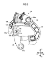
Fig. 7 is a view illustrating a state of the lock operation lever when the inside opening lever is rotatably operated to a final position; -
Fig. 8 is a view illustrating a state of the lock operation lever which is forcibly driven toward the locking position when the inside opening lever is located at the final position illustrated inFig. 7 ; and -
Fig. 9 is a partially enlarged view ofFig. 8 , and is a view for illustrating an operation of a lever actuating mechanism allocated to the lock mechanism. - Hereinafter, an embodiment of this disclosure will be described with reference to the drawings. In the drawings, a forward direction of a vehicle and a rearward direction of the vehicle are respectively illustrated by an arrow X1 and an arrow X2, and an upward direction of the vehicle and a downward direction with respect to the vehicle are respectively illustrated by an arrow Y1 and an arrow Y2. These directions can be applied to a vehicle door lock device in a state before being attached to a vehicle door, or a vehicle door lock device in a state after being attached to the vehicle door.
- A vehicle door lock device (hereinafter, simply also referred to as a "door lock device") 100 according to this embodiment illustrated in
Fig. 1 is mounted on a region defined by a door outer panel (vehicle exterior side panel) and a door inner panel (vehicle interior side panel) of a vehicle door DR.Fig. 1 illustrates a vehicle door on the right side of a vehicle as a representative example of the vehicle door DR. - The
door lock device 100 includes ahousing 101 for accommodating or assembling door lock configuration elements of the door lock device. The door lock configuration elements include alatch mechanism 110 and alock mechanism 120. - As is known, the
latch mechanism 110 is intended to maintain a state where the vehicle door DR is closed in a vehicle body BD. Thelatch mechanism 110 includes a latch (not illustrated) which can engage with and disengage from a striker ST fixed to the vehicle body BD, a pole (not illustrated) which can engage with and disengage from the latch and which can maintain and quit the engagement between the striker ST and the latch, and a lift lever 111 which is integrated with the pole. The latch engages with the striker ST and an engagement state therebetween is maintained, thereby maintaining a state where the vehicle door DR is closed (latched state). On the other hand, the latch disengages from the striker ST and the striker ST is released from the latch, thereby switching the vehicle door DR from a closed state to an open state (unlatched state). Thelatch mechanism 110 corresponds to a "latch mechanism" according to an aspect of this disclosure. - The
lock mechanism 120 has a function of setting an unlocked state where thelatch mechanism 110 can disengage from the striker ST disposed in the vehicle body BD, or a locked state where the latch mechanism cannot disengage from the striker ST. Thelock mechanism 120 includes aninside opening lever 121, anoutside opening lever 122, anopening link 123, alock operation lever 124, and anelectric motor 127. Thelock mechanism 120 corresponds to a "lock mechanism" according to an aspect of this disclosure. - The
inside opening lever 121 is connected to aninside door handle 10 which is a door operation handle disposed on an inner side of the vehicle door DR, via a flexible inside opening cable W. Therefore, a configuration is adopted in which theinside opening lever 121 is operated so as to be rotatable around a lever support portion (support shaft) 121 a disposed in thehousing 101 by a door opening operation of the inside door handle 10 from an initial position (position illustrated inFig. 2 ) to a maximum operation position (position illustrated inFig. 7 (also referred to as a "full position")) where theoutside opening lever 122 and theopening link 123 are lifted up by a predetermined amount. In this case, the maximum operation position of theinside opening lever 121 is defined as an operation position when theinside opening lever 121 is rotatably operated to the maximum on a basis of the initial position. For this purpose, theinside opening lever 121 can engage with and disengage from theoutside opening lever 122, and can engage with and disengage from thelock operation lever 124. Theinside opening lever 121 corresponds to an "inside opening lever" according to an aspect of this disclosure. - The
outside opening lever 122 is connected to an outside door handle (not illustrated) which is a door operation handle disposed on an outer side of the vehicle door DR. Therefore, a configuration is adopted in which theoutside opening lever 122 is operated so as to be rotatable around a lever support portion (not illustrated) by a door opening operation of the outside door handle from an initial position to an operation position. - The
opening link 123 is configured to be movable from an initial position to an operation position, when theinside opening lever 121 is rotatably operated from the initial position to the operation position, or when theoutside opening lever 122 is rotatably operated from the initial position to the operation position. Furthermore, theopening link 123 is configured to be switched to an unlocked position (unlocked state) which is the initial position when thelock operation lever 124 moves from a locking position to an unlocking position, and to be switched to a locked position (locked state) which is the operation position when thelock operation lever 124 moves from the unlocking position to the locking position. That is, theopening link 123 is switched between the unlocked state and the locked state in response to a rotatable operation of thelock operation lever 124 between the unlocking position and the locking position. - When the
opening link 123 is located at the unlocking position (first position) in a closed state of the vehicle door DR, an operation in a door opening direction of the respective opening levers 121 and 122 in response to a door opening operation of the respective door handles is transferred to the lift lever 111 which is a configuration element of thelatch mechanism 110 via theopening link 123. That is, the lift lever 111 of thelatch mechanism 110 is pressed by theopening link 123 and is rotatably operated, thereby switching thelatch mechanism 110 from the latched state to the unlatched state. As a result, the vehicle door DR is unlocked. On the other hand, when theopening link 123 is located at the locking position (second position) in the closed state of the vehicle door DR, the operation in the door opening direction of the respective opening levers 121 and 122 in response to the door opening operation of the respective door handles is transferred to theopening link 123, but is not transferred from theopening link 123 to the lift lever 111 which is a configuration element of thelatch mechanism 110. That is, theopening link 123 does not engage with the lift lever 111 of thelatch mechanism 110, and thelatch mechanism 110 maintains the latched state without any change. As a result, the vehicle door DR is not unlocked. Theopening link 123 corresponds to an "opening link" according to an aspect of this disclosure. - The
lock operation lever 124 can be operated so as to be rotatable around alever support portion 124a disposed in thehousing 101 between an unlocking position for setting theopening link 123 to be located at the unlocking position (first position) and a locking position for setting theopening link 123 to be located at the locking position (second position). Thelock operation lever 124 is pressed against theinside opening lever 121 which is rotatably operated by the door opening operation of the inside door handle 10 from the initial position illustrated inFig. 2 to the maximum operation position illustrated inFigs. 7 and8 , and is driven from the locking position to the unlocking position. Thelock operation lever 124 corresponds to a "lock operation lever" according to an aspect of this disclosure. - As illustrated in
Fig. 2 , thelock operation lever 124 includes a first lever portion (also referred to as an "inside locking lever") 125 and a second lever portion (also referred to as an "active lever") 126. A configuration is adopted in which thefirst lever portion 125 and thesecond lever portion 126 can be integrally operated so as to be rotatable around the commonlever support portion 124a. Theelectric motor 127 is configured to function as an actuator for driving thelock operation lever 124. Thesecond lever portion 126 of thelock operation lever 124 includes anengagement target portion 126a with which anengagement portion 121c disposed in theinside opening lever 121 can engage. Theengagement target portion 126a includes a curved slidingsurface 126b for engaging with theengagement portion 121c and a projectingportion 126c projecting toward theinside opening lever 121, in a region facing theinside opening lever 121. If necessary, thelock operation lever 124 can be configured to include one lever member in which a portion corresponding to thefirst lever portion 125 and a portion corresponding to thesecond lever portion 126 are integrated with each other. - As illustrated in
Fig. 3 , the inside opening cable W includes a cable end portion Wa having a crank shape (step-like shape) in a cross-sectional view, and is connected to theinside opening lever 121 by inserting the cable end portion Wa into anattachment hole 121b of theinside opening lever 121. - For example, a more specific configuration of the
latch mechanism 110 and thelock mechanism 120 can refer to a "latch mechanism", an "opening mechanism", and a "lock mechanism" which are disclosed in Reference 1. - The
lock mechanism 120 having the above-described configuration has a lever drive mechanism, a so-called "double-pulling mechanism" mounted thereon. The lever drive mechanism utilizes a structure in which theinside opening lever 121 drives thelock operation lever 124 from the locking position to the unlocking position during the door opening operation of theinside door handle 10. In the lever drive mechanism, a drive start timing of thelock operation lever 124 using theinside opening lever 121 is set to be delayed than a drive start timing of theopening link 123 using theinside opening lever 121. - In a case of this double-pulling mechanism, the
opening link 123 is switched from the locking position to the unlocking position when theinside opening lever 121 is rotatably operated from the initial position to the maximum operation position (also referred to as a "full position") by the first door opening operation of theinside door handle 10. Therefore, the vehicle door DR is not unlocked by the first door opening operation of theinside door handle 10. Thereafter, during a process while theinside opening lever 121 is rotatably operated again from the initial position to the maximum operation position by the second door opening operation of theinside door handle 10, theopening link 123 previously located at the unlocking position engages with the lift lever 111 of thelatch mechanism 110. Accordingly, thelatch mechanism 110 is switched from the latched state to the unlatched state so that the vehicle door DR is unlocked. - Hereinafter, referring to
Figs. 4 to 7 , a manner will be described in detail in which thelock operation lever 124 having the above-described configuration is rotatably operated from the initial position illustrated inFig. 2 to the maximum operation position in thelock mechanism 120 having the double-pulling mechanism mounted thereon. - During the door opening operation of the
inside door handle 10 inFig. 1 , theinside opening lever 121 located at the initial position is rotatably operated counterclockwise around thelever support portion 121 a. When theinside opening lever 121 is rotatably operated counterclockwise to reach a first operation position illustrated inFig. 4 , theengagement portion 121c of theinside opening lever 121 comes into contact with the slidingsurface 126b facing theengagement portion 121c within theengagement target portion 126a of thesecond lever portion 126. In this case, theengagement portion 121c of theinside opening lever 121 which attempts to be rotatably operated further counterclockwise presses the slidingsurface 126b while sliding thereon. In this manner, the lock operation lever 124 (thefirst lever portion 125 and the second lever portion 126) is rotatably operated clockwise around thelever support portion 124a. - Thereafter, the
inside opening lever 121 passes through a second operation position illustrated inFig. 5 , and is rotatably operated to reach a third operation position where theinside opening lever 121 crosses over the projectingportion 126c disposed on the slidingsurface 126b of theengagement target portion 126a as illustrated inFig. 6 . At this time, thesecond lever portion 126 is hit by theengagement portion 121c of theinside opening lever 121 so as to be separated from theengagement portion 121c, and is further rotatably operated clockwise together with thefirst lever portion 125 by atorsion spring 128 which elastically actuates thesecond lever portion 126 clockwise. As a result, theinside opening lever 121 forms a clearance 129 between theengagement target portion 126a of thesecond lever portion 126 and theinside opening lever 121, in a state where theinside opening lever 121 is rotatably operated to reach the maximum operation position illustrated inFig. 7 . - Incidentally, in some cases, the
lock operation lever 124 is forcibly driven counterclockwise toward the locking position due to automatic lock control or manual control of thelock operation lever 124 when theinside opening lever 121 is located at the maximum operation position illustrated inFig. 7 . Typically, this operation of thelock operation lever 124 can occur due to first control or second control described below. The first control is specified as the automatic lock control in which a vehicle speed sensor (not illustrated) detects that vehicle speed reaches a preset threshold value and thus theelectric motor 127 serving as an actuator forcibly drives thelock operation lever 124 counterclockwise toward the locking position. The second control is specified as the manual control in which a vehicle occupant operates a manual switch in order to perform the lock operation of thelock operation lever 124 and thus theelectric motor 127 forcibly drives thelock operation lever 124 counterclockwise toward the locking position. - In a case of the first control or the second control, as illustrated in
Fig. 8 , thesecond lever portion 126 comes into contact with theengagement portion 121c of theinside opening lever 121. At this time, if theinside opening lever 121 receives a load from thesecond lever portion 126 so that theinside opening lever 121 is kept at the maximum operation position or receives a load from thesecond lever portion 126 so that theinside opening lever 121 is actuated counterclockwise, theinside opening lever 121 cannot properly return to the initial position even after returning to the initial position by quitting the door opening operation of theinside door handle 10, and is kept at the maximum operation position. As a result, the flexible inside opening cable W connected to theinside opening lever 121 is bent, thereby causing a disadvantage that the cable end portion Wa of the inside opening cable W drops out from theattachment hole 121 b of theinside opening lever 121 or the cable end portion Wa itself buckles by being pressed against theinside opening lever 121. - Therefore, according to the embodiment disclosed here, as illustrated in
Fig. 9 , alever actuating mechanism 130 is allocated to thelock mechanism 120. When theinside opening lever 121 is located at the maximum operation position where theinside opening lever 121 comes into contact with thelock operation lever 124 which is driven from the unlocking position to the locking position, thelever actuating mechanism 130 has a function of actuating theinside opening lever 121 toward the initial position by using a contact load which theinside opening lever 121 receives from thelock operation lever 124. Thelever actuating mechanism 130 corresponds to a "lever actuating mechanism" according to an aspect of this disclosure. - According to this
lever actuating mechanism 130, it is possible to avoid a case where theinside opening lever 121 is blocked by thelock operation lever 124 at the maximum operation position. Thus, theinside opening lever 121 is rotatably operated around thelever support portion 121 a in a direction of an arrow R inFig. 9 , and can return to the initial position. In this case, when theinside door handle 10 returns to the initial position by quitting the door opening operation, theinside opening lever 121 also properly returns to the initial position. Therefore, a proper operation of theinside opening lever 121 is allowed when thelock operation lever 124 is forcibly driven toward the locking position. At this time, a state is maintained where proper tension is applied to the flexible inside opening cable W. As a result, it is possible to prevent the inside opening cable W from being bent. Accordingly, it is possible to prevent a disadvantage that the cable end portion Wa of the inside opening cable W drops out from theattachment hole 121b of theinside opening lever 121 or the cable end portion Wa itself buckles by being pressed against theinside opening lever 121. - In particular, the
lever actuating mechanism 130 is configured by using a structure of theinside opening lever 121 and thelock operation lever 124. To be more specific, in thelever actuating mechanism 130, theinside opening lever 121 and thelock operation lever 124 have a configuration in which a direction vector of the contact load received by theinside opening lever 121 at the maximum operation position is a normal vector N intersecting a connecting line L3 which connects thelever support portion 121 a (rotation center point Pb) of theinside opening lever 121 and a contact point Pa so as to actuate theinside opening lever 121 toward the initial position on a normal line L2 at the contact point Pa between theinside opening lever 121 and thelock operation lever 124. Typically, it is possible to determine, for example, relative geometric shapes, relative dimensions, and relative arrangements of theinside opening lever 121 and thelock operation lever 124 so that a desired normal vector N can be obtained as the direction vector of the contact load received by theinside opening lever 121 from thelock operation lever 124 at the maximum operation position. In this manner, theinside opening lever 121 can reliably return to the initial position by using the normal vector N at the contact point Pa between theinside opening lever 121 and thelock operation lever 124. In addition, thelever actuating mechanism 130 is built by using theinside opening lever 121 and thelock operation lever 124 which are existing configuration elements of thelock mechanism 120. Accordingly, it is possible to realize the inexpensivedoor lock device 100 without increasing the number of components. - Without being limited to the above-described representative embodiment, it is conceivable that this disclosure can be applied or modified in various ways. For example, the following forms can also be embodied by applying the above-described embodiment.
- In the above-described embodiment, a double-pulling mechanism has been described which is one of mechanisms for differentiating between a drive start timing of the
opening link 123 using theinside opening lever 121 and a drive start timing of thelock operation lever 124 using theinside opening lever 121. However, this disclosure can employ a so-called "one-motion mechanism" instead of the double-pulling mechanism. According to the one-motion mechanism, when theinside door handle 10 is used once for the door opening operation, an operation in which theopening link 123 is switched from the locking position to the unlocking position and an operation in which theopening link 123 engages with the lift lever 111 of thelatch mechanism 110 are continuously performed so that the vehicle door DR is unlocked. Similarly to a case of the double-pulling mechanism, even in a case of the one-motion mechanism, a situation can occur in which the operation of theinside opening lever 121 for returning to the initial position is blocked by thelock operation lever 124. Therefore, this disclosure can also be similarly applied to the lock mechanism having the one-motion mechanism mounted thereon. - In the above-described embodiment, the
lever actuating mechanism 130 has been described which has a function of avoiding a case where the operation of theinside opening lever 121 for returning to the initial position is blocked by thelock operation lever 124 when theinside opening lever 121 is located at the maximum operation position. However, according to an aspect of this disclosure, a target position of theinside opening lever 121 provided with a function of thelever actuating mechanism 130 is not limited to the maximum operation position. As the target position, it is possible to appropriately select any desired operation position within a range from the initial position to the maximum operation position of theinside opening lever 121. - According to an aspect of this disclosure, an essential structure of the above-described
door lock device 100 can be applied to each vehicle door of a vehicle. For example, the essential structure of thedoor lock device 100 according to an aspect of this disclosure can be applied to right and left doors for vehicle front seats, can be applied to right and left doors for vehicle rear seats, and can be further applied to a vehicle rear side door (rear door). - The principles, preferred embodiment and mode of operation of the present invention have been described in the foregoing specification. However, the invention which is intended to be protected is not to be construed as limited to the particular embodiments disclosed. Further, the embodiments described herein are to be regarded as illustrative rather than restrictive. Variations and changes may be made by others, and equivalents employed, without departing from the spirit of the present invention. Accordingly, it is expressly intended that all such variations, changes and equivalents which fall within the spirit and scope of the present invention as defined in the claims, be embraced thereby.
- A vehicle door lock device (100) includes: a latch mechanism (110) configured to enable a vehicle door (DR) to maintain a closed state in a vehicle body (BD); and a lock mechanism (120) configured to set an unlocked state or a locked state, wherein the lock mechanism includes an inside opening lever (121) connected to an inside door handle (10), and capable of being operated so as to be rotatable around a lever support portion (121 a) between an initial position and a maximum operation position, an opening link (123) capable of switching between a first position and a second position, a lock operation lever (124) capable of being operated so as to be rotatable around the lever support portion between an unlocking position and a locking position, and a lever actuating mechanism (130) actuating the inside opening lever toward the initial position.
Claims (2)
- A vehicle door lock device (100) comprising:a latch mechanism (110) configured to enable a vehicle door (DR) to maintain a closed state in a vehicle body (BD); anda lock mechanism (120) configured to set an unlocked state where the latch mechanism can disengage from a striker (ST) disposed in the vehicle body or a locked state where the latch mechanism cannot disengage from the striker,wherein the lock mechanism includes
an inside opening lever (121) that is connected to an inside door handle (10) disposed on an inner side of the vehicle door via a flexible inside opening cable (W), and that can be operated so as to be rotatable around a lever support portion (121 a) between an initial position and a maximum operation position in response to door opening and closing operations of the inside door handle,
an opening link (123) that can switch between a first position where an operation in a door opening direction of the inside opening lever in response to a door opening operation of the inside door handle is transferred to the latch mechanism and a second position where the operation in the door opening direction of the inside opening lever is not transferred to the latch mechanism,
a lock operation lever (124) that can be operated so as to be rotatable around the lever support portion between an unlocking position for setting the opening link to be located at the first position and a locking position for setting the opening link to be located at the second position, that is pressed by the inside opening lever which is rotatably operated from the initial position to the maximum operation position due to the door opening operation of the inside door handle, and that is driven from the locking position to the unlocking position, and
a lever actuating mechanism (130) that actuates the inside opening lever toward the initial position by using a contact load which the inside opening lever receives from the lock operation lever, when the inside opening lever is located at a predetermined operation position where the inside opening lever comes into contact with the lock operation lever which is driven from the unlocking position to the locking position within a range from the initial position to the maximum operation position. - The vehicle door lock device according to claim 1,
wherein in the lever actuating mechanism, the inside opening lever and the lock operation lever have a configuration in which a direction vector of the contact load received by the inside opening lever at the predetermined operation position is a normal vector intersecting a connecting line which connects the lever support portion of the inside opening lever and a contact point so as to actuate the inside opening lever toward the initial position on a normal line at the contact point between the inside opening lever and the lock operation lever.
Applications Claiming Priority (1)
| Application Number | Priority Date | Filing Date | Title |
|---|---|---|---|
| JP2014114890A JP6308031B2 (en) | 2014-06-03 | 2014-06-03 | Vehicle door lock device |
Publications (2)
| Publication Number | Publication Date |
|---|---|
| EP2952658A1 true EP2952658A1 (en) | 2015-12-09 |
| EP2952658B1 EP2952658B1 (en) | 2017-02-01 |
Family
ID=53365798
Family Applications (1)
| Application Number | Title | Priority Date | Filing Date |
|---|---|---|---|
| EP15169792.7A Active EP2952658B1 (en) | 2014-06-03 | 2015-05-29 | Vehicle door lock device |
Country Status (4)
| Country | Link |
|---|---|
| US (1) | US10246913B2 (en) |
| EP (1) | EP2952658B1 (en) |
| JP (1) | JP6308031B2 (en) |
| CN (1) | CN204715938U (en) |
Families Citing this family (5)
| Publication number | Priority date | Publication date | Assignee | Title |
|---|---|---|---|---|
| CN105421908B (en) * | 2015-12-23 | 2017-07-18 | 重庆怡海科技发展有限公司 | A kind of special purpose vehicle car door lock of use ratchet holding and retaining mechanism |
| TWI567280B (en) * | 2016-01-15 | 2017-01-21 | 信昌機械廠股份有限公司 | Tamper-proof device of vehicle door lock |
| WO2018207256A1 (en) * | 2017-05-09 | 2018-11-15 | 本田技研工業株式会社 | Vehicular latch device |
| JP2019111881A (en) * | 2017-12-21 | 2019-07-11 | 三井金属アクト株式会社 | Slide door support device |
| JP6895943B2 (en) * | 2018-12-12 | 2021-06-30 | 株式会社ハイレックスコーポレーション | Mobile device |
Citations (3)
| Publication number | Priority date | Publication date | Assignee | Title |
|---|---|---|---|---|
| FR2815988A1 (en) * | 2000-10-26 | 2002-05-03 | Ohi Seisakusho Co Ltd | DOOR LOCKING ASSEMBLY FOR MOTOR VEHICLES |
| JP2011026867A (en) | 2009-07-27 | 2011-02-10 | Aisin Seiki Co Ltd | Door lock device for vehicle |
| US20110254287A1 (en) * | 2010-03-24 | 2011-10-20 | Aisin Seiki Kabushiki Kaisha | Vehicle door lock device |
Family Cites Families (9)
| Publication number | Priority date | Publication date | Assignee | Title |
|---|---|---|---|---|
| DE10334607B4 (en) * | 2002-07-29 | 2012-09-20 | Aisin Seiki K.K. | Door locking device |
| JP3914139B2 (en) * | 2002-11-27 | 2007-05-16 | 三井金属鉱業株式会社 | Door latch device |
| DE10360982A1 (en) * | 2002-12-24 | 2004-10-07 | Aisin Seiki K.K., Kariya | Torque transmission element and door locking device |
| JP2004251106A (en) * | 2003-01-30 | 2004-09-09 | Aisin Seiki Co Ltd | Door lock device |
| GB2424036B (en) * | 2004-03-30 | 2007-02-21 | Mitsui Mining & Smelting Co | Door lock system |
| JP4542166B2 (en) * | 2008-03-26 | 2010-09-08 | 三井金属鉱業株式会社 | Door lock device |
| EP2412903B1 (en) * | 2009-03-24 | 2016-03-23 | Aisin Seiki Kabushiki Kaisha | Door lock device for vehicle |
| JP4953485B2 (en) * | 2010-02-15 | 2012-06-13 | 三井金属アクト株式会社 | Vehicle door latch device |
| DE102015000824A1 (en) * | 2014-01-23 | 2015-07-23 | Magna Closures Inc. | Door lock device for motor vehicles |
-
2014
- 2014-06-03 JP JP2014114890A patent/JP6308031B2/en active Active
-
2015
- 2015-05-29 EP EP15169792.7A patent/EP2952658B1/en active Active
- 2015-06-01 US US14/727,355 patent/US10246913B2/en active Active
- 2015-06-03 CN CN201520377831.0U patent/CN204715938U/en active Active
Patent Citations (4)
| Publication number | Priority date | Publication date | Assignee | Title |
|---|---|---|---|---|
| FR2815988A1 (en) * | 2000-10-26 | 2002-05-03 | Ohi Seisakusho Co Ltd | DOOR LOCKING ASSEMBLY FOR MOTOR VEHICLES |
| JP2011026867A (en) | 2009-07-27 | 2011-02-10 | Aisin Seiki Co Ltd | Door lock device for vehicle |
| EP2460960A1 (en) * | 2009-07-27 | 2012-06-06 | Aisin Seiki Kabushiki Kaisha | Door lock device for vehicle |
| US20110254287A1 (en) * | 2010-03-24 | 2011-10-20 | Aisin Seiki Kabushiki Kaisha | Vehicle door lock device |
Also Published As
| Publication number | Publication date |
|---|---|
| JP6308031B2 (en) | 2018-04-11 |
| US10246913B2 (en) | 2019-04-02 |
| US20150345191A1 (en) | 2015-12-03 |
| EP2952658B1 (en) | 2017-02-01 |
| JP2015229824A (en) | 2015-12-21 |
| CN204715938U (en) | 2015-10-21 |
Similar Documents
| Publication | Publication Date | Title |
|---|---|---|
| EP2952658B1 (en) | Vehicle door lock device | |
| US10954702B2 (en) | Leveled opening control | |
| JP6155488B2 (en) | Locking device having a claw portion having a plurality of parts | |
| CN107916847B (en) | Power closed latch assembly including tie pull mechanism with ratchet retention | |
| US7021681B2 (en) | Door lock device | |
| US8684424B2 (en) | Closing assisted electric lock for opening of automobile | |
| US11421454B2 (en) | Closure latch assembly with latch mechanism and outside release mechanism having reset device | |
| US6964438B2 (en) | Door lock device for a vehicle | |
| JP5663714B2 (en) | Handle of automatic vehicle door opening / closing body | |
| US20150240537A1 (en) | Latch for a door of a motor vehicle | |
| JP6420703B2 (en) | Vehicle door handle device | |
| US8979145B2 (en) | Door lock apparatus | |
| US8814226B2 (en) | Door lock device for vehicle | |
| EP3309006B1 (en) | Sliding armrest for vehicle | |
| EP2784252A2 (en) | Motor vehicle lock | |
| CN108397061B (en) | Vehicle back door locking device | |
| KR20190141182A (en) | Car lock | |
| US10934746B2 (en) | Lock for a motor vehicle door leaf | |
| US20200102772A1 (en) | Vehicle door latch device | |
| US20170306658A1 (en) | Motor vehicle lock comprising a braking pawl and a driving dog mechanism | |
| US11384563B2 (en) | Spring retaining assembly for vehicle latch actuator mechanism | |
| US20220251886A1 (en) | Door latch device and actuator | |
| CN114008284B (en) | Lock for motor vehicle | |
| CN111065789B (en) | Motor vehicle door lock | |
| KR20060062052A (en) | Structure for preventing releasing of door latch |
Legal Events
| Date | Code | Title | Description |
|---|---|---|---|
| PUAI | Public reference made under article 153(3) epc to a published international application that has entered the european phase |
Free format text: ORIGINAL CODE: 0009012 |
|
| AK | Designated contracting states |
Kind code of ref document: A1 Designated state(s): AL AT BE BG CH CY CZ DE DK EE ES FI FR GB GR HR HU IE IS IT LI LT LU LV MC MK MT NL NO PL PT RO RS SE SI SK SM TR |
|
| AX | Request for extension of the european patent |
Extension state: BA ME |
|
| 17P | Request for examination filed |
Effective date: 20151106 |
|
| RBV | Designated contracting states (corrected) |
Designated state(s): AL AT BE BG CH CY CZ DE DK EE ES FI FR GB GR HR HU IE IS IT LI LT LU LV MC MK MT NL NO PL PT RO RS SE SI SK SM TR |
|
| GRAP | Despatch of communication of intention to grant a patent |
Free format text: ORIGINAL CODE: EPIDOSNIGR1 |
|
| RIC1 | Information provided on ipc code assigned before grant |
Ipc: E05B 77/32 20140101ALI20160712BHEP Ipc: E05B 81/16 20140101AFI20160712BHEP |
|
| INTG | Intention to grant announced |
Effective date: 20160810 |
|
| GRAS | Grant fee paid |
Free format text: ORIGINAL CODE: EPIDOSNIGR3 |
|
| GRAA | (expected) grant |
Free format text: ORIGINAL CODE: 0009210 |
|
| AK | Designated contracting states |
Kind code of ref document: B1 Designated state(s): AL AT BE BG CH CY CZ DE DK EE ES FI FR GB GR HR HU IE IS IT LI LT LU LV MC MK MT NL NO PL PT RO RS SE SI SK SM TR |
|
| REG | Reference to a national code |
Ref country code: GB Ref legal event code: FG4D |
|
| REG | Reference to a national code |
Ref country code: CH Ref legal event code: EP Ref country code: AT Ref legal event code: REF Ref document number: 865755 Country of ref document: AT Kind code of ref document: T Effective date: 20170215 |
|
| REG | Reference to a national code |
Ref country code: IE Ref legal event code: FG4D |
|
| REG | Reference to a national code |
Ref country code: DE Ref legal event code: R096 Ref document number: 602015001400 Country of ref document: DE |
|
| REG | Reference to a national code |
Ref country code: FR Ref legal event code: PLFP Year of fee payment: 3 |
|
| REG | Reference to a national code |
Ref country code: NL Ref legal event code: MP Effective date: 20170201 |
|
| REG | Reference to a national code |
Ref country code: LT Ref legal event code: MG4D |
|
| REG | Reference to a national code |
Ref country code: AT Ref legal event code: MK05 Ref document number: 865755 Country of ref document: AT Kind code of ref document: T Effective date: 20170201 |
|
| PG25 | Lapsed in a contracting state [announced via postgrant information from national office to epo] |
Ref country code: HR Free format text: LAPSE BECAUSE OF FAILURE TO SUBMIT A TRANSLATION OF THE DESCRIPTION OR TO PAY THE FEE WITHIN THE PRESCRIBED TIME-LIMIT Effective date: 20170201 Ref country code: IS Free format text: LAPSE BECAUSE OF FAILURE TO SUBMIT A TRANSLATION OF THE DESCRIPTION OR TO PAY THE FEE WITHIN THE PRESCRIBED TIME-LIMIT Effective date: 20170601 Ref country code: FI Free format text: LAPSE BECAUSE OF FAILURE TO SUBMIT A TRANSLATION OF THE DESCRIPTION OR TO PAY THE FEE WITHIN THE PRESCRIBED TIME-LIMIT Effective date: 20170201 Ref country code: NO Free format text: LAPSE BECAUSE OF FAILURE TO SUBMIT A TRANSLATION OF THE DESCRIPTION OR TO PAY THE FEE WITHIN THE PRESCRIBED TIME-LIMIT Effective date: 20170501 Ref country code: LT Free format text: LAPSE BECAUSE OF FAILURE TO SUBMIT A TRANSLATION OF THE DESCRIPTION OR TO PAY THE FEE WITHIN THE PRESCRIBED TIME-LIMIT Effective date: 20170201 Ref country code: GR Free format text: LAPSE BECAUSE OF FAILURE TO SUBMIT A TRANSLATION OF THE DESCRIPTION OR TO PAY THE FEE WITHIN THE PRESCRIBED TIME-LIMIT Effective date: 20170502 |
|
| PG25 | Lapsed in a contracting state [announced via postgrant information from national office to epo] |
Ref country code: LU Free format text: LAPSE BECAUSE OF NON-PAYMENT OF DUE FEES Effective date: 20170531 Ref country code: RS Free format text: LAPSE BECAUSE OF FAILURE TO SUBMIT A TRANSLATION OF THE DESCRIPTION OR TO PAY THE FEE WITHIN THE PRESCRIBED TIME-LIMIT Effective date: 20170201 Ref country code: NL Free format text: LAPSE BECAUSE OF NON-PAYMENT OF DUE FEES Effective date: 20170201 Ref country code: ES Free format text: LAPSE BECAUSE OF FAILURE TO SUBMIT A TRANSLATION OF THE DESCRIPTION OR TO PAY THE FEE WITHIN THE PRESCRIBED TIME-LIMIT Effective date: 20170201 Ref country code: LV Free format text: LAPSE BECAUSE OF FAILURE TO SUBMIT A TRANSLATION OF THE DESCRIPTION OR TO PAY THE FEE WITHIN THE PRESCRIBED TIME-LIMIT Effective date: 20170201 Ref country code: SE Free format text: LAPSE BECAUSE OF FAILURE TO SUBMIT A TRANSLATION OF THE DESCRIPTION OR TO PAY THE FEE WITHIN THE PRESCRIBED TIME-LIMIT Effective date: 20170201 Ref country code: PL Free format text: LAPSE BECAUSE OF FAILURE TO SUBMIT A TRANSLATION OF THE DESCRIPTION OR TO PAY THE FEE WITHIN THE PRESCRIBED TIME-LIMIT Effective date: 20170201 Ref country code: BG Free format text: LAPSE BECAUSE OF FAILURE TO SUBMIT A TRANSLATION OF THE DESCRIPTION OR TO PAY THE FEE WITHIN THE PRESCRIBED TIME-LIMIT Effective date: 20170501 Ref country code: AT Free format text: LAPSE BECAUSE OF FAILURE TO SUBMIT A TRANSLATION OF THE DESCRIPTION OR TO PAY THE FEE WITHIN THE PRESCRIBED TIME-LIMIT Effective date: 20170201 Ref country code: PT Free format text: LAPSE BECAUSE OF FAILURE TO SUBMIT A TRANSLATION OF THE DESCRIPTION OR TO PAY THE FEE WITHIN THE PRESCRIBED TIME-LIMIT Effective date: 20170601 |
|
| PG25 | Lapsed in a contracting state [announced via postgrant information from national office to epo] |
Ref country code: RO Free format text: LAPSE BECAUSE OF FAILURE TO SUBMIT A TRANSLATION OF THE DESCRIPTION OR TO PAY THE FEE WITHIN THE PRESCRIBED TIME-LIMIT Effective date: 20170201 Ref country code: EE Free format text: LAPSE BECAUSE OF FAILURE TO SUBMIT A TRANSLATION OF THE DESCRIPTION OR TO PAY THE FEE WITHIN THE PRESCRIBED TIME-LIMIT Effective date: 20170201 Ref country code: IT Free format text: LAPSE BECAUSE OF FAILURE TO SUBMIT A TRANSLATION OF THE DESCRIPTION OR TO PAY THE FEE WITHIN THE PRESCRIBED TIME-LIMIT Effective date: 20170201 Ref country code: SK Free format text: LAPSE BECAUSE OF FAILURE TO SUBMIT A TRANSLATION OF THE DESCRIPTION OR TO PAY THE FEE WITHIN THE PRESCRIBED TIME-LIMIT Effective date: 20170201 Ref country code: CZ Free format text: LAPSE BECAUSE OF FAILURE TO SUBMIT A TRANSLATION OF THE DESCRIPTION OR TO PAY THE FEE WITHIN THE PRESCRIBED TIME-LIMIT Effective date: 20170201 |
|
| REG | Reference to a national code |
Ref country code: DE Ref legal event code: R097 Ref document number: 602015001400 Country of ref document: DE |
|
| PG25 | Lapsed in a contracting state [announced via postgrant information from national office to epo] |
Ref country code: SM Free format text: LAPSE BECAUSE OF FAILURE TO SUBMIT A TRANSLATION OF THE DESCRIPTION OR TO PAY THE FEE WITHIN THE PRESCRIBED TIME-LIMIT Effective date: 20170201 Ref country code: DK Free format text: LAPSE BECAUSE OF FAILURE TO SUBMIT A TRANSLATION OF THE DESCRIPTION OR TO PAY THE FEE WITHIN THE PRESCRIBED TIME-LIMIT Effective date: 20170201 |
|
| PLBE | No opposition filed within time limit |
Free format text: ORIGINAL CODE: 0009261 |
|
| STAA | Information on the status of an ep patent application or granted ep patent |
Free format text: STATUS: NO OPPOSITION FILED WITHIN TIME LIMIT |
|
| 26N | No opposition filed |
Effective date: 20171103 |
|
| PG25 | Lapsed in a contracting state [announced via postgrant information from national office to epo] |
Ref country code: MC Free format text: LAPSE BECAUSE OF FAILURE TO SUBMIT A TRANSLATION OF THE DESCRIPTION OR TO PAY THE FEE WITHIN THE PRESCRIBED TIME-LIMIT Effective date: 20170201 |
|
| REG | Reference to a national code |
Ref country code: IE Ref legal event code: MM4A |
|
| PG25 | Lapsed in a contracting state [announced via postgrant information from national office to epo] |
Ref country code: SI Free format text: LAPSE BECAUSE OF FAILURE TO SUBMIT A TRANSLATION OF THE DESCRIPTION OR TO PAY THE FEE WITHIN THE PRESCRIBED TIME-LIMIT Effective date: 20170201 |
|
| PG25 | Lapsed in a contracting state [announced via postgrant information from national office to epo] |
Ref country code: LU Free format text: LAPSE BECAUSE OF NON-PAYMENT OF DUE FEES Effective date: 20170529 |
|
| REG | Reference to a national code |
Ref country code: FR Ref legal event code: PLFP Year of fee payment: 4 |
|
| REG | Reference to a national code |
Ref country code: BE Ref legal event code: MM Effective date: 20170531 |
|
| PG25 | Lapsed in a contracting state [announced via postgrant information from national office to epo] |
Ref country code: IE Free format text: LAPSE BECAUSE OF NON-PAYMENT OF DUE FEES Effective date: 20170529 |
|
| PG25 | Lapsed in a contracting state [announced via postgrant information from national office to epo] |
Ref country code: BE Free format text: LAPSE BECAUSE OF NON-PAYMENT OF DUE FEES Effective date: 20170531 |
|
| PG25 | Lapsed in a contracting state [announced via postgrant information from national office to epo] |
Ref country code: MT Free format text: LAPSE BECAUSE OF NON-PAYMENT OF DUE FEES Effective date: 20170529 |
|
| REG | Reference to a national code |
Ref country code: CH Ref legal event code: PL |
|
| PG25 | Lapsed in a contracting state [announced via postgrant information from national office to epo] |
Ref country code: LI Free format text: LAPSE BECAUSE OF NON-PAYMENT OF DUE FEES Effective date: 20180531 Ref country code: CH Free format text: LAPSE BECAUSE OF NON-PAYMENT OF DUE FEES Effective date: 20180531 |
|
| PG25 | Lapsed in a contracting state [announced via postgrant information from national office to epo] |
Ref country code: HU Free format text: LAPSE BECAUSE OF FAILURE TO SUBMIT A TRANSLATION OF THE DESCRIPTION OR TO PAY THE FEE WITHIN THE PRESCRIBED TIME-LIMIT; INVALID AB INITIO Effective date: 20150529 |
|
| PG25 | Lapsed in a contracting state [announced via postgrant information from national office to epo] |
Ref country code: CY Free format text: LAPSE BECAUSE OF FAILURE TO SUBMIT A TRANSLATION OF THE DESCRIPTION OR TO PAY THE FEE WITHIN THE PRESCRIBED TIME-LIMIT Effective date: 20170201 |
|
| PG25 | Lapsed in a contracting state [announced via postgrant information from national office to epo] |
Ref country code: MK Free format text: LAPSE BECAUSE OF FAILURE TO SUBMIT A TRANSLATION OF THE DESCRIPTION OR TO PAY THE FEE WITHIN THE PRESCRIBED TIME-LIMIT Effective date: 20170201 |
|
| GBPC | Gb: european patent ceased through non-payment of renewal fee |
Effective date: 20190529 |
|
| PG25 | Lapsed in a contracting state [announced via postgrant information from national office to epo] |
Ref country code: TR Free format text: LAPSE BECAUSE OF FAILURE TO SUBMIT A TRANSLATION OF THE DESCRIPTION OR TO PAY THE FEE WITHIN THE PRESCRIBED TIME-LIMIT Effective date: 20170201 |
|
| PG25 | Lapsed in a contracting state [announced via postgrant information from national office to epo] |
Ref country code: GB Free format text: LAPSE BECAUSE OF NON-PAYMENT OF DUE FEES Effective date: 20190529 |
|
| PG25 | Lapsed in a contracting state [announced via postgrant information from national office to epo] |
Ref country code: AL Free format text: LAPSE BECAUSE OF FAILURE TO SUBMIT A TRANSLATION OF THE DESCRIPTION OR TO PAY THE FEE WITHIN THE PRESCRIBED TIME-LIMIT Effective date: 20170201 |
|
| PGFP | Annual fee paid to national office [announced via postgrant information from national office to epo] |
Ref country code: FR Payment date: 20220408 Year of fee payment: 8 |
|
| PGFP | Annual fee paid to national office [announced via postgrant information from national office to epo] |
Ref country code: DE Payment date: 20230404 Year of fee payment: 9 |