EP2952396B1 - Seat belt device for the vehicle seat - Google Patents
Seat belt device for the vehicle seat Download PDFInfo
- Publication number
- EP2952396B1 EP2952396B1 EP15168445.3A EP15168445A EP2952396B1 EP 2952396 B1 EP2952396 B1 EP 2952396B1 EP 15168445 A EP15168445 A EP 15168445A EP 2952396 B1 EP2952396 B1 EP 2952396B1
- Authority
- EP
- European Patent Office
- Prior art keywords
- striker
- webbing
- occupant
- shoulder
- hole
- Prior art date
- Legal status (The legal status is an assumption and is not a legal conclusion. Google has not performed a legal analysis and makes no representation as to the accuracy of the status listed.)
- Not-in-force
Links
Images


Classifications
-
- B—PERFORMING OPERATIONS; TRANSPORTING
- B60—VEHICLES IN GENERAL
- B60N—SEATS SPECIALLY ADAPTED FOR VEHICLES; VEHICLE PASSENGER ACCOMMODATION NOT OTHERWISE PROVIDED FOR
- B60N2/00—Seats specially adapted for vehicles; Arrangement or mounting of seats in vehicles
- B60N2/68—Seat frames
- B60N2/688—Particular seat belt attachment and guiding
-
- B—PERFORMING OPERATIONS; TRANSPORTING
- B60—VEHICLES IN GENERAL
- B60N—SEATS SPECIALLY ADAPTED FOR VEHICLES; VEHICLE PASSENGER ACCOMMODATION NOT OTHERWISE PROVIDED FOR
- B60N2/00—Seats specially adapted for vehicles; Arrangement or mounting of seats in vehicles
- B60N2/64—Back-rests or cushions
-
- B—PERFORMING OPERATIONS; TRANSPORTING
- B60—VEHICLES IN GENERAL
- B60R—VEHICLES, VEHICLE FITTINGS, OR VEHICLE PARTS, NOT OTHERWISE PROVIDED FOR
- B60R22/00—Safety belts or body harnesses in vehicles
- B60R22/02—Semi-passive restraint systems, e.g. systems applied or removed automatically but not both ; Manual restraint systems
- B60R22/023—Three-point seat belt systems comprising two side lower and one side upper anchoring devices
- B60R22/024—Adaptations for use by small passengers, e.g. children
-
- B—PERFORMING OPERATIONS; TRANSPORTING
- B60—VEHICLES IN GENERAL
- B60R—VEHICLES, VEHICLE FITTINGS, OR VEHICLE PARTS, NOT OTHERWISE PROVIDED FOR
- B60R22/00—Safety belts or body harnesses in vehicles
- B60R22/12—Construction of belts or harnesses
-
- B—PERFORMING OPERATIONS; TRANSPORTING
- B60—VEHICLES IN GENERAL
- B60R—VEHICLES, VEHICLE FITTINGS, OR VEHICLE PARTS, NOT OTHERWISE PROVIDED FOR
- B60R22/00—Safety belts or body harnesses in vehicles
- B60R22/18—Anchoring devices
- B60R22/26—Anchoring devices secured to the seat
-
- B—PERFORMING OPERATIONS; TRANSPORTING
- B60—VEHICLES IN GENERAL
- B60R—VEHICLES, VEHICLE FITTINGS, OR VEHICLE PARTS, NOT OTHERWISE PROVIDED FOR
- B60R22/00—Safety belts or body harnesses in vehicles
- B60R22/18—Anchoring devices
- B60R2022/1806—Anchoring devices for buckles
-
- B—PERFORMING OPERATIONS; TRANSPORTING
- B60—VEHICLES IN GENERAL
- B60R—VEHICLES, VEHICLE FITTINGS, OR VEHICLE PARTS, NOT OTHERWISE PROVIDED FOR
- B60R22/00—Safety belts or body harnesses in vehicles
- B60R22/18—Anchoring devices
- B60R2022/1818—Belt guides
Definitions
- This invention relates to a seat belt device for the vehicle seat, which is designed to hold an occupant to the vehicle seat.
- the three-point holding seat belt is broadly used to hold the occupant to the vehicle seat, at three points, i.e., the left or right shoulder and the left and right hips.
- the three-point holding seat belt (or three-point seat belt) comprise webbing.
- the webbing is taken up as a pulling force is applied to it from the retractor incorporated in, for example, a chassis pillar.
- the webbing extends from the retractor, through the webbing feed port made in the pillar provided on the chassis wall and located above the upper end of the vehicle seat.
- the occupant may hold, with hand, the tongue mounted on the webbing and insert the tongue into the buckle provided on one side of the seat cushion.
- the upper half of the webbing used as a shoulder webbing is thereby wrapped around the occupant, slantwise from one shoulder, and the lower half of the webbing used as a lap webbing is wrapped around the hips.
- the seat belt holds the occupant to the vehicle seat.
- the seat belt may fail to function effectively if the occupant undergoes a so-called submarine phenomenon, i.e., forward motion with his or her buttocks sinking in the seat cushion.
- the webbing feed port made in the pillar is located positioned much farther above the occupant's shoulder than in the case an adult of ordinary physique wears the three-point holding seat belt.
- the gap (hereinafter referred to as "gap") between the shoulder webbing extending from the webbing feed port and the occupant's shoulder and the seatback is relatively large. Even if the webbing is tightened at an emergency to reduce the gap immediately, the seat belt can hardly press the occupant's shoulders onto the vehicle seat (more precisely, seatback) to hold the occupant steadily.
- a three-point holding seat belt designed to control effectively the submarine phenomenon a small occupant may undergo is known. (Refer to, for example, JP 2010-173358A , JP 05-112204A and JP 2010-058723A .)
- a first height adjusting mechanism is provided in a pillar, and a second height adjusting mechanism is provided on an upper part of that side of a seatback, which faces the pillar.
- the first and second height adjusting mechanisms adjust the height (position) of the upper end of the shoulder webbing extending from the occupant's shoulder, reducing the above-mentioned gap.
- Each of the first and second height adjusting mechanisms is composed of a base member and a sliding member.
- the base member is shaped like a flat plate extending in vertical direction.
- the base member of the first and the second height adjusting mechanisms are secured, respectively to the wall of the pillar and that side of the seatback, which faces the pillar.
- the sliding members may slide up and down on the base members, respectively, and each can be locked at a given position (height) on the associated base member.
- the sliding member of the first height adjusting mechanism has a webbing guide hole.
- the sliding member of the second height adjusting mechanism has a hook for catching the webbing.
- the occupant In order to wear the webbing, the occupant first adjusts the heights of the sliding members of the first and second height adjusting mechanisms, locking the sliding members, each at the given positions on the associated base member. Then, the occupant pulls the webbing from the webbing feed port made in the pillar, passes the webbing through the webbing guide hole of the first height adjusting mechanism and fastens the webbing extending through the webbing guide hole to the hook of the second height adjusting mechanism. Now extending through the first and second height adjusting mechanisms, the webbing extending slantwise from the occupant's shoulder is wrapped around the occupant's hips.
- a guide anchor is provided on that upper part of the side of the seatback, which faces the pillar.
- the guide anchor has a webbing guide hole, through which the webbing passes, and can be moved on that upper part of the side of the seatback, to a given position (height), by means of an electric drive mechanism.
- the shoulder webbing extending from the webbing feed port made in the pillar passes through the webbing guide hole of the guide anchor and is wrapped around the occupant's hips from the occupant's shoulder.
- a guide anchor is provided on the upper part of the back of the seatback, which opposes the pillar.
- the guide anchor has a main part and an arm part.
- the main part has a webbing guide hole for guiding the webbing.
- the arm part supports the main part from below.
- the arm part is coupled, at lower end, to a drive mechanism.
- the arm part can be swung around its lower end as the drive mechanism operates.
- the main part of the guide anchor In normal state, the main part of the guide anchor is positioned at the upper edge of that side of seatback, which opposes the pillar.
- the shoulder webbing extends from the webbing feed port made in the pillar. Then, the shoulder webbing is guided through the webbing guide hole and wrapped around the occupant's shoulder.
- the drive mechanism constituted by, for example, an inflator, operates, swinging the guide anchor to one side of the seatback from the upper edge of the seatback, which lies near the pillar.
- the sliding member is changed in position with respect to the base members of the first and second height adjusting mechanisms.
- the upper end of the shoulder webbing extending to the occupant's shoulder is thereby adjusted in height (position), reducing the above-mentioned gap.
- the second height adjusting mechanisms may be used to adjust the position of the sliding member, allowing the webbing to extend from the occupant's side, not from above the occupant's shoulder. This narrows the gap.
- the second height adjusting mechanism is, however, secured to the upper edge of the seatback, which lies near the pillar.
- the shoulder webbing will be spaced from the occupant's shoulder if the occupant is small in physique.
- a gap (distance) extending in the widthwise direction of the vehicle seat is provided between the shoulder webbing and the occupant's shoulder.
- the gap is broader than in the case where the occupant has ordinary physique.
- the shoulder webbing cannot be tightened to hold the occupant in emergency, and can hardly control the submarine phenomenon.
- the guide anchor is changed in position at an upper part of that side of a seatback.
- the height (position) of the upper end of the shoulder webbing extending to the occupant's shoulder is thereby adjusted, narrowing the gap.
- the drive mechanism operates in emergency, rotating the main part of the guide anchor around the lower end of the arm part.
- the main part of the guide anchor therefore moves to the side of the seatback from the upper edge of the seatback, which lies near the pillar.
- the gap is thereby reduced.
- the angle through which the guide anchor may rotate cannot be set in accordance with the occupant's physique.
- the seat belt may fail to hold well a small occupant in emergency.
- an inflator for example, must be used as drive mechanism to operate in emergency, the configuration is inevitably complicated.
- the drive mechanism fails to operate in emergency, the occupant cannot be held, and the submarine phenomenon may not be controlled.
- DE202007009815U1 is considered to represent the most relevant state of the art and discloses a system according to the preamble of claim 1.
- An object of this invention is to provide a seat belt device for the vehicle seat, which has a simple configuration and which can hold an occupant to the vehicle seat in emergency and control the submarine phenomenon, even if the occupant is small in physique.
- the upper-front part of a seatback is cut, providing a hole at which the occupant's shoulder may lie, and an engaging means is fitted in the hole.
- the engaging means holds the shoulder webbing, which is wrapped around the occupant.
- a system comprises a seat belt device, a vehicle seat and a pillar, further comprises a webbing having a tongue and extending from a webbing feed port made in the pillar, when the tongue is inserted into a buckle provided on one side of a seat cushion, the upper half of the webbing used as a shoulder webbing is wrapped slantwise around the shoulder of the occupant sitting on the vehicle seat, and the lower half of the webbing used as a lap webbing is wrapped around the hips of the occupant, thereby holding the occupant to the vehicle seat, further comprising a hole provided by cutting the seatback at an upper-front part, and a striker being shaped like a cantilever, having a free end at an inner end, extending in the left-right direction in the hole, and being able to engage with the shoulder webbing, the free end is pushed, a part of the shoulder webbing is passed through a gap between the free end and an inner side of the hole, inserted and guided through the striker, when a
- the engaging means is fitted in the hole located at the occupant's shoulder, a gap is scarcely provided between the shoulder webbing and the occupant's shoulder and seatback.
- the shoulder webbing can therefore be tightened in emergency, and can hold even an occupant of small physique to the vehicle seat, preventing the submarine phenomenon.
- the vehicle seat 10 has two rear seats 12 (seats 12L and 12R) arranged side by side.
- Each of the left and right seats 12 (seats 12L and 12R) comprises a seat cushion 14 and a seatback 16.
- the seatback 16 is coupled to the seat cushion 14 and can be folded forward to the seat cushion.
- a headrest 17 is mounted on the top of the seatback 16.
- arrows Fr and Rr indicate the forward and backward directions of the vehicle seat 10
- L and R indicate the leftward and rightward directions of the vehicle seat 10.
- the seat cushion 14 and the seatback 16 have basic structures well known in the art.
- the seatback 16 for example, comprises a seatback frame and a seat pad 16a.
- the seatback frame is composed of left and right side frames and a connecting pipe connecting the upper ends of the left and right side frames, and is therefore shaped like letter U.
- the right side frame 16c is shown in FIG. 2B .
- the seat pad 16a made of foamed material such as urethane foam is mounted on the seatback frame and is covered with a trim cover 16b having air permeability.
- the seat cushion 14 comprises a seat cushion frame, a seat pad (16a, shown in FIG. 1C .), and a trim cover (16b, shown in FIG. 1C .).
- the seat cushion frame is composed of left and right side frames and a connecting pipe connecting the front parts of the left and right side frames, and is therefore shaped like letter U.
- the seat pad (16a, shown in FIG. 1C .) is mounted on the seat cushion frame and is covered with the trim cover (16b, shown in FIG. 1C .).
- Either seat belt 18 is a three-point holding seat belt and comprises a webbing 18c.
- a retractor 18a is provided in the chassis pillar 18b.
- the retractor 18a has taken up the webbing 18c with a traction force, and stores the webbing 18c.
- the distal end of the webbing 18c extends from the retractor 18a, passing through the webbing feed port 18b' made in the pillar wall and located above the upper edge of the vehicle seat 10.
- first and second tongues 18d1 and 18d2 are mounted and can freely slide.
- reference number 18c indicates the shoulder webbing 18c1, unless otherwise specified.
- Buckles (first buckles) 18e1 are provided, respectively close to the center parts of the seat backs of the left and right rear seats 12 (12L and 12R). Each buckle 18e1 has, for example, one part embedded in the associated rear seat. The first tongues 18d1 is inserted in the first buckle 18e1 and engaged therewith.
- the upper-front part 16F of each seatback is cut, providing a hole 20, which may be positioned at the tip of the occupant's shoulder.
- the hole 20 is a bottomed hole, but is not limited the bottomed hole and a through hole may be used as the hole.
- the shoulder webbing 18c is set in engagement with an engaging means 30 provided in the hole 20, and is wrapped slantwise around the occupant from the occupant's shoulder to the buckle 18e1 provided at one side of the seat cushion.
- the engaging means 30 is another buckle (second buckle) 18e2 arranged in the hole 20, and the second tongue (intermediate tongue) 18d2 mounted on the shoulder webbing 18c is inserted into the second buckle and engaged therewith.
- the seat pad (seatback member) 16a made of, for example, foamed urethane, is covered with the trim cover 16b.
- the seat pad (seatback member) 16a is cut, providing the hole 20 in the upper-front part of the seatback.
- the hole 20 opens at front and has a cross section shaped like a rectangle.
- the second buckle 18e2 is arranged and embedded in the hole 20 and has an engaging port 18e2' extending in vertical direction and opening at front.
- the second buckle 18e2 is spaced apart from the front 16F of the seatback, and is arranged and embedded in the hole 20 (thus, in the seatback).
- the shape and structure of the second buckle 18e2 are not limited to those specified above. Rather, the second buckle 18e2 may be embedded in the hole 20, with the engaging port 18e2' of the second buckle orientated slantwise and upward, so that it may easily catch the second tongue (intermediate tongue) 18d2. Further, the second buckle 18e2 may not be embedded and immovably fitted in the hole 20, scarcely leaving a gap, as shown in FIGS. 1B and 1C . Instead, the second buckle 18e2 may rotate in the hole, around a rotation axle (not shown) provided in the hole. When the second buckle 18e2 may rotate in the hole 20 around a rotation axle, its orientation can be freely adjusted. This makes it easy to insert the second tongue 18d2 into the engaging port 18e2'.
- the first buckle 18e1 and the second buckle 18e2 provided in the hole 20 have, for example, the same shape. Nonetheless, each buckle may be changed in shape in accordance with, for example, the size of the seat
- the shoulder webbing 18c is wrapped around the occupant, with its widthwise direction aligned with the left-right direction.
- the second buckle 18e2 is embedded in the hole 20, and its engaging port 18e2' extends in the vertical direction.
- the shoulder webbing 18c is therefore twisted as shown in FIG. 1C , and its widthwise direction is therefore changed from the left-right direction to the vertical direction.
- the second tongue 18d2 is thereby inserted into the engaging port 18e2'. If the buckle 18e2 is embedded in the hole 20 so that the engaging port 18e2' may extend in the left-right direction, however, the second tongue 18d2 can be inserted into the engaging port without twisting the shoulder webbing 18c.
- the occupant may pull the shoulder webbing 18c after it has engaged with the engaging means 30 (i.e., buckle 18e2), and insert the first tongue 18d1 into the first buckle 18e1.
- the upper half 18c1 of the webbing as the shoulder webbing is thereby wrapped around the occupant, slantwise from the occupant's left shoulder.
- the lower half 18c2 of the webbing as the lap webbing is wrapped around the occupant's hips, holding the occupant to one seat of the vehicle seat 10.
- the shoulder webbing 18c is wrapped around the occupant, after set into engagement with the engaging means 30 (i.e., buckle 18e2) which is held in the hole 20 made in the upper-front part 16F and which is located at the occupant's shoulder. Since the shoulder webbing 18c extends from the occupant's shoulder, a gap is scarcely provided between the occupant's shoulder and the shoulder webbing and front of the seat back. Therefore, the retractor 18a can tighten the shoulder webbing 18c in the case of emergency, immediately holding the occupant to the vehicle seat even if the occupant is small in physique. The seat belt can thus control the submarine phenomenon.
- the engaging means 30 i.e., buckle 18e2
- the engaging means 30 held in the hole is not used at all, and either the tongue 18d1 or the tongue 18d2 is set into engagement with the buckle 18e1 as in the seat belt device well known in the art. That is, if the occupant has ordinary physique, it suffices to wrap the shoulder webbing 18c around the occupant, without setting the shoulder webbing 18c into engagement with the engaging means 30. In this case, too, the retractor 18a can tighten the shoulder webbing 18c in emergency, to hold the occupant to the vehicle seat in the same manner as usual. Needless to say, the engaging means, which is provided in the hole, would not contact, for example, the back of the occupant, not preventing the occupant from being well seated, even if the occupant has ordinary physique.
- the second buckle 18e2 (engaging means 30) is embedded in the hole 20 made by cutting the upper-front part 16F of the seatback, and the second tongue (intermediate tongue) 18d2 able to engage with the second buckle is provided on the shoulder webbing 18c.
- These configuration features can instantly hold the occupant to the vehicle seat in emergency, reducing the gap between the webbing and the occupant. It is therefore unnecessary to use any drive mechanism for moving the engaging means to an appropriate position in emergency, such as an electric drive mechanism or an inflator. This simplifies the structure of the seat belt device.
- the second buckle 18e2 (engaging means 30) is embedded in the hole 20 and does not protrude from the front of the seatback.
- the engaging means (second buckle) never contacts the back of the occupant, and would not prevent the occupant from being well seated.
- the second buckle 18e2 remains well embedded in the hole 20, the second tongue 18d2 will not protrude from the front of the seatback even if it is inserted in the engaging port 18e2' of the second buckle.
- the second tongue never contact the back of the occupant seated, and the occupant wrapped with the shoulder webbing 18c is never prevented from being well seated.
- Embodiment 2 shown in FIGS. 2A to 2C will be described.
- the components identical to those of the embodiment described above (Embodiment 1) are designated by the same reference numbers, and will not be described.
- the components distinguishing Embodiment 2 form Embodiment 1 will be described in the main.
- Embodiment 2 differs from Embodiment 1 in that a striker is embedded in the hole 20, not the buckle 18e2 as in Embodiment 1.
- the striker 32 is shaped like a cantilever, and its inner end (close to the vertical centerline of the seat) is the free end.
- the striker 32 shaped like a cantilever extends in the hole in the left-right direction from, for example, the outer side 20S (pillar-side) of the hole.
- the distal end (inner end) of the striker is a free end, and spaced from the inner side 20S' of the hole.
- a part of the striker, for example the middle part 32b, is bent twice, forming a stepped part.
- the hole 20 is shown as a bottomed hole.
- the hole 20 is not limited to a bottomed hole and a through hole may be used as the hole.
- the shoulder webbing 18c is bent back at the intermediate part, and is substantially U-shaped.
- the part of the shoulder webbing, so bent back, is engaged with the striker 32 provided in the hole 20.
- the shoulder webbing is wrapped slantwise around the occupant's shoulder.
- FIGS. 3A to 3E and FIG. 3F show a modification of Embodiment 2.
- the free end 32a is pushed rearwards (see FIG. 3B ).
- the part of the shoulder webbing 18c, bent back as describe above, is passed first through the gap between the free end 32a and the inner side 20S' of the hole, is inserted, and guided through the striker 32 (see FIG. 3C ).
- the bent-back part of the shoulder webbing 18c may be inserted and engaged with the striker 32 as the engaging means 30, and the shoulder webbing 18c may then be wrapped slantwise around the occupant's shoulder. Then, a gap is scarcely provided between the shoulder webbing and the occupant's shoulder and seatback, in the same way as in Embodiment 1.
- the shoulder webbing 18c can therefore be tightened in emergency, holding the occupant to the vehicle seat even if the occupant is small in physique.
- the seat belt can thus control the submarine phenomenon.
- the striker 32 in the hole 20 and guide the bent-back part of the shoulder webbing 18c through the striker. This helps to simplify the structure of the configuration of the seat belt device. Needless to say, the striker 32, which is provided in the hole, would not prevent the occupant from being well seated, even if the occupant has ordinary physique. When the shoulder webbing is wrapped around the occupant's shoulder, without being engaged with the engaging means 30 (striker 32), the occupant can be held well to the vehicle seat and submarine phenomenon can be controlled. The striker 32 never prevents an occupant of ordinary physique, as well as an occupant of small physique, from being seated well in the vehicle seat.
- the striker may be bent twice at middle part 32b as shown in FIGS. 3A to 3F , to have a stepped part. Then, the striker can therefore catch the shoulder webbing 18c at bent-back part more easily than otherwise, and can prevent the shoulder webbing from slipping sideways.
- the free end 32a of the striker may be bent as shown in FIG. 3F .
- the striker can reliably prevent the shoulder webbing 18c from slipping sideways and falling down from the free end of the striker.
- the free end 32a of the striker is bent backwards. Instead, the free end of the striker may be bent forwards and may guide the shoulder webbing 18c. Further, the free end 32a of the striker may not be bent forwards, the bent-back part of the shoulder webbing 18c may be passed through the gap between the free end and the inner side 20S' of the hole, and may then be guided by the striker.
- the striker 32 extends from the pillar-side 20S of the hole in the left-right direction.
- the fixed end 32c of the striker may be secured to a locking means 40 (more precisely, bracket 49 described later) configured to lock the seatback in a standing position.
- the locking means may be used as striker.
- the fixed end 32c of the striker may be secured to one side frame (i.e., the right side frame 16c) of the seatback frame.
- the locking means 40 has such a known configuration as shown in FIGS. 3A to 5F appended to JP 2011-162163A that is a patent application filed by the applicant hereof.
- the locking means 40 has, for example, a gate-shaped striker 42 and a latch 44.
- the latch 44 can rotate to come into engagement with the striker 42. Once the latch 44 has been engaged with the striker 42, the seatback 16 is fixed in the standing position.
- the latch 44 of the locking means is provided at an upper part of one side of the seatback 16.
- the gate-shaped striker 42 is secured to the pillar 18b opposing the latch 44.
- the gate-shaped striker 42 has two legs (front leg 42F and rear leg 42R), and is shaped like letter U.
- the latch 44 of the locking means 40 is clamped between a base plate 46 and a cover plate 48, forming a unit together with the plates 46 and 48.
- the unit has a bracket 49 formed integral.
- the bracket is secured to the frame of the seatback 16 (i.e., seatback frame).
- the latch 44 of the locking means is thereby attached to the upper part of one side of the seatback.
- the fixed end 32c of the striker is connected to the bracket 49, and is secured thereto.
- a shaft 44S extends between the base plate 46 and the cover plate 48.
- the latch 44 is provided between the base plate and the cover plate and can rotate around the shaft 44S.
- a biasing means such as a torsion spring (not shown) is wound around, for example, the shaft 44S, and applies a force F to the latch 44, biasing the latch 44 to rotate clockwise around the shaft 44S as indicate by an arrow shown in FIG. 5A .
- the latch 44 is thereby set in at an initial position.
- the gate-shaped striker 42 is secured to the pillar 18b, with the front leg 42F and rear leg 42R positioned in the locus of a slit 45 located at the standing position of the seatback.
- the latch of the locking means operates as the seatback assumes its standing position.
- the operation of the latch will therefore be briefly explained.
- the slit 45 of the locking means moves along a locus 45' shown in FIG. 5B .
- the front leg 42F and rear leg 42R of the gate-shaped striker are positioned.
- the first face 44a1 of the latch 44 which extends across the slit, abuts on the front leg (see FIG. 5B ).
- the first face 44a1 is a slope curved like an arc. Therefore, the latch 44 rotates against the bias force F, moving away from the front leg (as seen in the direction of the arrow shown in FIG. 5C ), as the front leg 42F is guided, sliding on the first face.
- the front leg 42F moves from the first face 44a1 to the second face 44a2 of the latch 44 and abuts on the second face 44a2.
- the front leg 42F then slides on the second face 44a2 that is a slope curved like an arc, similar to the first face 44a1.
- the latch 44 further rotates against the bias force F, moving away from the front leg.
- the front leg 42F moves over beyond the second face 44a2, slipping into a storage space 44c
- the rear leg 42R slides on the first face 44a1, moves beyond the first face and is held in a locking groove 44b (see FIG. 5D ).
- the seatback 16 is held in its standing position.
- the bracket 49 of the locking means 40 connects the fixed end 32c of the striker to the latch 44.
- the striker 32 is therefore stably secured, by the locking means 40 (bracket 49), to the gate-shaped striker 42 and the pillar 18b when the seatback 16 is rotated to its standing position.
- an inertial force acts, via the striker 32 (engaging means 30), on the occupant wearing the shoulder webbing 18c, to move the occupant forwards.
- the inertial force is transmitted to the striker through the shoulder webbing.
- the inertial force generated in emergency escapes to the locking means 40 via the bracket if the fixed end 32c of the striker is connected and secured to the bracket 49.
- the gate-shaped striker 42 may be secured to the bracket 49 (latch 44) in any other manner.
- the fixed end 32c of the striker is secured to the pillar 18b, and the gate-shaped striker 42 is secure to the bracket 49 (latch 44) provided on the upper part of one side of the seatback.
- the gate-shaped striker 42 or latch 44 provided on the seatback may be connected to one side frame (i.e., the right side frame 16c) of the seatback frame. If connected to one side frame of the seatback frame, the striker 42 or latch 44 is stably fixed and can therefore transmit the inertial force generated in emergency to the side frame.
- any shaft secured at a specific position and extending in the left-right direction for example the shaft 44S of the latch 44, may be utilized as striker. Further, the fixed end 32c of the striker may be fixed to one side frame of the seatback frame.
- FIGS. 6A to 6C show Embodiment 3 that does not form part of the invention but represents background art that is useful for understanding the invention.
- the components identical to those of the embodiments described above are designated by the same reference numbers, and will not be described.
- the components distinguishing Embodiment 3 from Embodiments 1 and 2 will be described in the
- Embodiments 1 and 2 a hole is made by cutting an upper-front part of the seatback.
- a hole is made by cutting through an upper-front part of the seatback.
- the engaging means is the second buckle located in the hole (bottomed hole or through hole), and in Embodiment 2 the striker located in the hole (through hole or bottomed hole).
- the engaging means is the striker arranged at the back of the hole (through hole). Embodiment 3 differs in these respects from Embodiments 1 and 2.
- a hole (through hole) 120 is cut through the upper-front part 16F of the seatback and may be positioned at the occupant's shoulder, and an engaging means 130 is spaced from the back of the seatback.
- the hole 120 has a cross section shaped like a rectangle. The shape of the cross section is not limited, nonetheless, so long as the shoulder webbing can pass through the hole.
- the engaging means 130 is a striker 132 shaped like a cantilever, and its inner end (i.e., inner side of the seat) is the free end. As seen from FIGS. 6A and 6B , the striker 132 has a fixed end 132c on the surface of a pillar 18b at the back of the hole 120, and extends toward the seat from the pillar.
- the free end 132a of the striker is bent upwards, for example.
- the shape of the free end 132a is not limited to this, nonetheless. If so bent, however, the free end 132a can prevent the shoulder webbing 18c from slipping sideways on the striker 132 or falling from the free end 132a.
- the middle part of the striker 132 may be bent twice at its middle part to have a stepped part. In this case, too, the shoulder webbing 18c can be prevented from slipping sideways or falling down.
- the free end 132a of the striker may be bent back as shown in FIG. 3F .
- a support 16a' may be provided on the back of the seatback, thereby to support the striker 132 as it is deformed (bent) toward the back of the seatback.
- the support 16a' is mounted on the back of the seatback and located in front of the free end 132a of the striker and is made of, for example, elastic material and is semispherical in shape.
- the engaging means 130 (striker 132) shown in FIGS. 6A to 6C operates will be explained.
- a part of the shoulder webbing 18c is bent back at the intermediated part and is substantially U-shaped. The part so bent is guided from the free end 132a of the striker through the hole 120 and is engaged with the striker 132. So engaged by the engaging means 130, the shoulder webbing 18c is wrapped slantwise around the occupant, from the occupant's shoulder to the buckle 18e1 provided on one side of the seat cushion.
- Embodiment 3 can achieve the same technical advantage as in Embodiments 1 and 2, i.e., to reduce the gap between the shoulder webbing 18c and the occupant's shoulder. This is because the shoulder webbing 18c is first engaged with the engaging means 130 (striker 132) and then wrapped slantwise around the occupant's shoulder. Hence, the shoulder webbing 18c can be instantaneously tightened in emergency and control submarine phenomenon even if the occupant has small physique.
- the shoulder webbing may be wrapped around the shoulder, without being engaged with the engaging means (striker 132). In this case, the shoulder webbing is tightened in emergency, holding the occupant well to the vehicle seat and hence preventing the submarine phenomenon.
- the striker 132 never prevents an occupant of ordinary physique, as well as an occupant of small physique, from being seated well in the vehicle seat.
- the striker 132 extends from the pillar 18b (more precisely, from the surface thereof).
- the inertial force acting on the occupant in emergency is therefore transmitted through the shoulder webbing 18c to the striker. If the fixed end 132c of the striker is secured to the pillar 18b, the inertial force escapes to the pillar through the striker.
- the striker 132 is spaced from the back of the seatback. If the back of the seatback has a horizontal hole communicating with the hole 120 and the striker 132 extends in the horizontal hole, the striker is embedded in the horizontal hole, not exposed at all. This prevents the vehicle seat from being degraded in outer appearance.
- the seat belt device can hold even an occupant of small physique to the vehicle seat in emergency, thereby to control the submarine phenomenon, without using any additional components. If the occupant has ordinary physique, he or she only needs to wrap the shoulder webbing around him or her, without engaging the shoulder webbing with the engaging means. Needless to say, the seat belt device can hold the occupant of ordinary physique, too, to the vehicle seat in emergency, thereby to control the submarine phenomenon.
- this invention is not limited to vehicle seats in buses and automobiles.
- the invention can be applied also to train seats and airplane seats, to pull the seat-belt webbing in emergency, thereby to control the submarine phenomenon.
Description
- This invention relates to a seat belt device for the vehicle seat, which is designed to hold an occupant to the vehicle seat.
- As a seat belt device for holding an occupant to a vehicle seat, the three-point holding seat belt is broadly used to hold the occupant to the vehicle seat, at three points, i.e., the left or right shoulder and the left and right hips.
- The three-point holding seat belt (or three-point seat belt) comprise webbing. The webbing is taken up as a pulling force is applied to it from the retractor incorporated in, for example, a chassis pillar. The webbing extends from the retractor, through the webbing feed port made in the pillar provided on the chassis wall and located above the upper end of the vehicle seat. The occupant may hold, with hand, the tongue mounted on the webbing and insert the tongue into the buckle provided on one side of the seat cushion. The upper half of the webbing used as a shoulder webbing is thereby wrapped around the occupant, slantwise from one shoulder, and the lower half of the webbing used as a lap webbing is wrapped around the hips. As a result, the seat belt holds the occupant to the vehicle seat.
- Recently, not only the occupant of a front seat, but also the occupant of a rear seat is obligated to wear a seat belt.
- If a vehicle is abruptly decelerated or stopped or if it collides with the vehicle running before, an inertial force acts on any occupant wearing the seat belt, to move the occupant forwards. Usually, the occupant is prevented from moving forwards due to the inertial force acting in such an emergency as the retractor tightens the webbing of the seat belt. As is pointed out, however, the seat belt may fail to function effectively if the occupant undergoes a so-called submarine phenomenon, i.e., forward motion with his or her buttocks sinking in the seat cushion.
- Most three-point holding seat belts are designed to hold adults of ordinary physique. Hence, if a small adult or a child wears the three-point holding seat belt, the webbing feed port made in the pillar is located positioned much farther above the occupant's shoulder than in the case an adult of ordinary physique wears the three-point holding seat belt. Inevitably, the gap (hereinafter referred to as "gap") between the shoulder webbing extending from the webbing feed port and the occupant's shoulder and the seatback is relatively large. Even if the webbing is tightened at an emergency to reduce the gap immediately, the seat belt can hardly press the occupant's shoulders onto the vehicle seat (more precisely, seatback) to hold the occupant steadily.
- A three-point holding seat belt designed to control effectively the submarine phenomenon a small occupant may undergo is known. (Refer to, for example,
JP 2010-173358A JP 05-112204A JP 2010-058723A - In the invention of
JP 2010-173358A - Each of the first and second height adjusting mechanisms is composed of a base member and a sliding member. The base member is shaped like a flat plate extending in vertical direction. The base member of the first and the second height adjusting mechanisms are secured, respectively to the wall of the pillar and that side of the seatback, which faces the pillar. The sliding members may slide up and down on the base members, respectively, and each can be locked at a given position (height) on the associated base member. The sliding member of the first height adjusting mechanism has a webbing guide hole. The sliding member of the second height adjusting mechanism has a hook for catching the webbing.
- In order to wear the webbing, the occupant first adjusts the heights of the sliding members of the first and second height adjusting mechanisms, locking the sliding members, each at the given positions on the associated base member. Then, the occupant pulls the webbing from the webbing feed port made in the pillar, passes the webbing through the webbing guide hole of the first height adjusting mechanism and fastens the webbing extending through the webbing guide hole to the hook of the second height adjusting mechanism. Now extending through the first and second height adjusting mechanisms, the webbing extending slantwise from the occupant's shoulder is wrapped around the occupant's hips.
- In the invention of JPH05-112204A, a guide anchor is provided on that upper part of the side of the seatback, which faces the pillar. The guide anchor has a webbing guide hole, through which the webbing passes, and can be moved on that upper part of the side of the seatback, to a given position (height), by means of an electric drive mechanism.
- The shoulder webbing extending from the webbing feed port made in the pillar passes through the webbing guide hole of the guide anchor and is wrapped around the occupant's hips from the occupant's shoulder.
- In the invention of
JP 2010-058723A - In normal state, the main part of the guide anchor is positioned at the upper edge of that side of seatback, which opposes the pillar. The shoulder webbing extends from the webbing feed port made in the pillar. Then, the shoulder webbing is guided through the webbing guide hole and wrapped around the occupant's shoulder. In emergency such as a side collision, the drive mechanism constituted by, for example, an inflator, operates, swinging the guide anchor to one side of the seatback from the upper edge of the seatback, which lies near the pillar.
- In the configuration disclosed in
JP 2010-173358A - The second height adjusting mechanism is, however, secured to the upper edge of the seatback, which lies near the pillar. Hence, even if the sliding member is adjusted in position in vertical direction with respect to the base member of the second height adjusting mechanism and the shoulder webbing is thereby extended, the shoulder webbing will be spaced from the occupant's shoulder if the occupant is small in physique. Inevitably, a gap (distance) extending in the widthwise direction of the vehicle seat is provided between the shoulder webbing and the occupant's shoulder. The gap is broader than in the case where the occupant has ordinary physique. The shoulder webbing cannot be tightened to hold the occupant in emergency, and can hardly control the submarine phenomenon.
- In the configuration of JPH 05-112204A, the guide anchor is changed in position at an upper part of that side of a seatback. The height (position) of the upper end of the shoulder webbing extending to the occupant's shoulder is thereby adjusted, narrowing the gap.
- To change the position of the guide anchor, however, an electric drive mechanism is indispensable. The use of this drive mechanism complicates the configuration.
- In the configuration of
JP 2010-058723A - However, the angle through which the guide anchor may rotate cannot be set in accordance with the occupant's physique. Hence, the seat belt may fail to hold well a small occupant in emergency. Further, an inflator, for example, must be used as drive mechanism to operate in emergency, the configuration is inevitably complicated. The drive mechanism fails to operate in emergency, the occupant cannot be held, and the submarine phenomenon may not be controlled.
-
DE202007009815U1 is considered to represent the most relevant state of the art and discloses a system according to the preamble of claim 1. - An object of this invention is to provide a seat belt device for the vehicle seat, which has a simple configuration and which can hold an occupant to the vehicle seat in emergency and control the submarine phenomenon, even if the occupant is small in physique.
- To achieve the above-mentioned object, the upper-front part of a seatback is cut, providing a hole at which the occupant's shoulder may lie, and an engaging means is fitted in the hole. The engaging means holds the shoulder webbing, which is wrapped around the occupant.
- In this invention of claim 1, a system comprises a seat belt device, a vehicle seat and a pillar, further comprises a webbing having a tongue and extending from a webbing feed port made in the pillar, when the tongue is inserted into a buckle provided on one side of a seat cushion, the upper half of the webbing used as a shoulder webbing is wrapped slantwise around the shoulder of the occupant sitting on the vehicle seat, and the lower half of the webbing used as a lap webbing is wrapped around the hips of the occupant, thereby holding the occupant to the vehicle seat, further comprising a hole provided by cutting the seatback at an upper-front part, and a striker being shaped like a cantilever, having a free end at an inner end, extending in the left-right direction in the hole, and being able to engage with the shoulder webbing, the free end is pushed, a part of the shoulder webbing is passed through a gap between the free end and an inner side of the hole, inserted and guided through the striker, when a force is released from the free end of the striker, the striker returns to an initial position, because of its resilient force, and the shoulder webbing is bent back, forming a bent part at the intermediated part and is substantially U-shaped, is engaged with the striker and then wrapped slantwise around the shoulder of the occupant.
- Since the engaging means is fitted in the hole located at the occupant's shoulder, a gap is scarcely provided between the shoulder webbing and the occupant's shoulder and seatback. The shoulder webbing can therefore be tightened in emergency, and can hold even an occupant of small physique to the vehicle seat, preventing the submarine phenomenon.
- Further, it suffices to provide a hole in the upper-front part of the seatback and to arrange an engaging means in the hole. No drive mechanisms such as an electric mechanism or an inflator are necessary. This helps to simplify the configuration of the seat belt device. Moreover, since the engaging means lies within the hole made in the upper-front part of the seatback, it never touches the occupant's back and never prevents the occupant from smoothly sitting on the vehicle seat.
-
-
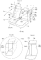
FIG. 1A is a schematic perspective view of a vehicle seat comprising a seat belt device according to one embodiment (Embodiment 1); -
FIG. 1B is a partly magnified view, showingpart 1B illustrated inFIG. 1A , and not showing the shoulder webbing for simplicity of drawing; -
FIG. 1C is a partly sectional view of thepart 1B illustrated inFIG. 1A , taken along the front-rear direction; -
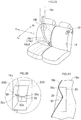
FIG. 2A is a schematic perspective view of a vehicle seat comprising a seat belt device according to another embodiment (Embodiment 2) of the present invention, not showing the lap webbing for simplicity of drawing; -
FIG. 2B is a partly magnified view, showingpart 2B illustrated inFIG. 2A , and not showing the shoulder webbing for simplicity of drawing; -
FIG. 2C is a partly sectional view of thepart 2B illustrated inFIG. 2A ; -
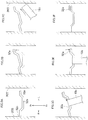
FIGS. 3A to 3E are schematic diagrams of a striker and a shoulder webbing; -
FIG. 3F is a schematic diagram showing the striker and shoulder webbing equivalent to those shown inFIG. 3A , which are used in a modification of the invention; -
FIGS. 4A and 4B are a partly rear perspective view and a partly schematic plan view, respectively, of a vehicle seat, illustrating a modification of this invention; -
FIG. 4C is a partly perspective view of a gate-shaped striker; -
FIG. 5A is a schematic front view of the locking means; -
FIGS. 5B to 5D are diagrams showing how the locking means performs latching; -
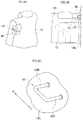
FIG. 6A is a schematic perspective view of a vehicle seat comprising a seat belt device according to an embodiment (embodiment 3) that does not form part of the invention but represents background art that is useful for understanding the invention; -
FIG. 6B is a partly magnified view, showingpart 6B illustrated inFIG. 6A , and not showing the shoulder webbing for simplicity of drawing; -
FIG. 6C is a partly sectional schematic view of thepart 6B illustrated inFIG. 6A ; and -
FIG. 7 is a partly schematic plan view of a vehicle seat comprising a striker and a stay. - The embodiments will be described in detail, with reference to the accompanying drawings. The first embodiment and
Figs. 1A-1C are only an example which contributes to understanding the present invention but do not form a part of the present invention. - As shown in
FIG. 1A , thevehicle seat 10 has two rear seats 12 (seats seats seat cushion 14 and aseatback 16. Theseatback 16 is coupled to theseat cushion 14 and can be folded forward to the seat cushion. Aheadrest 17 is mounted on the top of theseatback 16. - In the drawings, arrows Fr and Rr indicate the forward and backward directions of the
vehicle seat 10, and L and R indicate the leftward and rightward directions of thevehicle seat 10. - The
seat cushion 14 and theseatback 16 have basic structures well known in the art. Theseatback 16, for example, comprises a seatback frame and aseat pad 16a. The seatback frame is composed of left and right side frames and a connecting pipe connecting the upper ends of the left and right side frames, and is therefore shaped like letter U. (The right side frame 16c is shown inFIG. 2B .) As seen fromFIG. 1C , theseat pad 16a made of foamed material such as urethane foam is mounted on the seatback frame and is covered with atrim cover 16b having air permeability. Similarly, theseat cushion 14 comprises a seat cushion frame, a seat pad (16a, shown inFIG. 1C .), and a trim cover (16b, shown inFIG. 1C .). The seat cushion frame is composed of left and right side frames and a connecting pipe connecting the front parts of the left and right side frames, and is therefore shaped like letter U. The seat pad (16a, shown inFIG. 1C .) is mounted on the seat cushion frame and is covered with the trim cover (16b, shown inFIG. 1C .). - Either
seat belt 18 is a three-point holding seat belt and comprises awebbing 18c. Aretractor 18a is provided in thechassis pillar 18b. Theretractor 18a has taken up thewebbing 18c with a traction force, and stores thewebbing 18c. The distal end of thewebbing 18c extends from theretractor 18a, passing through thewebbing feed port 18b' made in the pillar wall and located above the upper edge of thevehicle seat 10. On the intermediate part of thewebbing 18c that extends from thewebbing feed port 18b', first and second tongues 18d1 and 18d2 are mounted and can freely slide. - Hereinafter,
reference number 18c indicates the shoulder webbing 18c1, unless otherwise specified. - Buckles (first buckles) 18e1 are provided, respectively close to the center parts of the seat backs of the left and right rear seats 12 (12L and 12R). Each buckle 18e1 has, for example, one part embedded in the associated rear seat. The first tongues 18d1 is inserted in the first buckle 18e1 and engaged therewith.
- In this embodiment, the upper-
front part 16F of each seatback is cut, providing ahole 20, which may be positioned at the tip of the occupant's shoulder. In Embodiment 1, thehole 20 is a bottomed hole, but is not limited the bottomed hole and a through hole may be used as the hole. - The
shoulder webbing 18c is set in engagement with an engagingmeans 30 provided in thehole 20, and is wrapped slantwise around the occupant from the occupant's shoulder to the buckle 18e1 provided at one side of the seat cushion. - As shown in
FIGS. 1A and 1B , the engagingmeans 30 is another buckle (second buckle) 18e2 arranged in thehole 20, and the second tongue (intermediate tongue) 18d2 mounted on theshoulder webbing 18c is inserted into the second buckle and engaged therewith. - As seen well from not only
FIGS. 1A and 1B , but alsoFIG. 1C , the seat pad (seatback member) 16a made of, for example, foamed urethane, is covered with thetrim cover 16b. The seat pad (seatback member) 16a is cut, providing thehole 20 in the upper-front part of the seatback. Thehole 20 opens at front and has a cross section shaped like a rectangle. - As shown in
FIGS. 1B and 1C , the second buckle 18e2 is arranged and embedded in thehole 20 and has an engaging port 18e2' extending in vertical direction and opening at front. The second buckle 18e2 is spaced apart from the front 16F of the seatback, and is arranged and embedded in the hole 20 (thus, in the seatback). - The shape and structure of the second buckle 18e2 are not limited to those specified above. Rather, the second buckle 18e2 may be embedded in the
hole 20, with the engaging port 18e2' of the second buckle orientated slantwise and upward, so that it may easily catch the second tongue (intermediate tongue) 18d2. Further, the second buckle 18e2 may not be embedded and immovably fitted in thehole 20, scarcely leaving a gap, as shown inFIGS. 1B and 1C . Instead, the second buckle 18e2 may rotate in the hole, around a rotation axle (not shown) provided in the hole. When the second buckle 18e2 may rotate in thehole 20 around a rotation axle, its orientation can be freely adjusted. This makes it easy to insert the second tongue 18d2 into the engaging port 18e2'. - The first buckle 18e1 and the second buckle 18e2 provided in the
hole 20 have, for example, the same shape. Nonetheless, each buckle may be changed in shape in accordance with, for example, the size of the seat - To wrap the
shoulder webbing 18c around the occupant, he or she first hold the two tongues 18d1 and 18d2 with hands, then pulls the shoulder webbing from thewebbing feed port 18b'. Then, the occupant inserts the second tongue 18d2 into the engaging port 18e2' of the second buckle provided in thehole 20. As a result, theshoulder webbing 18c is engaged. - As shown in
FIGS. 1B and 1C , theshoulder webbing 18c is wrapped around the occupant, with its widthwise direction aligned with the left-right direction. By contrast, the second buckle 18e2 is embedded in thehole 20, and its engaging port 18e2' extends in the vertical direction. Theshoulder webbing 18c is therefore twisted as shown inFIG. 1C , and its widthwise direction is therefore changed from the left-right direction to the vertical direction. The second tongue 18d2 is thereby inserted into the engaging port 18e2'. If the buckle 18e2 is embedded in thehole 20 so that the engaging port 18e2' may extend in the left-right direction, however, the second tongue 18d2 can be inserted into the engaging port without twisting theshoulder webbing 18c. - The occupant may pull the
shoulder webbing 18c after it has engaged with the engaging means 30 (i.e., buckle 18e2), and insert the first tongue 18d1 into the first buckle 18e1. The upper half 18c1 of the webbing as the shoulder webbing is thereby wrapped around the occupant, slantwise from the occupant's left shoulder. At the same time, the lower half 18c2 of the webbing as the lap webbing is wrapped around the occupant's hips, holding the occupant to one seat of thevehicle seat 10. - In this embodiment, the
shoulder webbing 18c is wrapped around the occupant, after set into engagement with the engaging means 30 (i.e., buckle 18e2) which is held in thehole 20 made in the upper-front part 16F and which is located at the occupant's shoulder. Since theshoulder webbing 18c extends from the occupant's shoulder, a gap is scarcely provided between the occupant's shoulder and the shoulder webbing and front of the seat back. Therefore, theretractor 18a can tighten theshoulder webbing 18c in the case of emergency, immediately holding the occupant to the vehicle seat even if the occupant is small in physique. The seat belt can thus control the submarine phenomenon. - If the occupant has ordinary physique, the engaging means 30 held in the hole is not used at all, and either the tongue 18d1 or the tongue 18d2 is set into engagement with the buckle 18e1 as in the seat belt device well known in the art. That is, if the occupant has ordinary physique, it suffices to wrap the
shoulder webbing 18c around the occupant, without setting theshoulder webbing 18c into engagement with the engagingmeans 30. In this case, too, theretractor 18a can tighten theshoulder webbing 18c in emergency, to hold the occupant to the vehicle seat in the same manner as usual. Needless to say, the engaging means, which is provided in the hole, would not contact, for example, the back of the occupant, not preventing the occupant from being well seated, even if the occupant has ordinary physique. - As described above, the second buckle 18e2 (engaging means 30) is embedded in the
hole 20 made by cutting the upper-front part 16F of the seatback, and the second tongue (intermediate tongue) 18d2 able to engage with the second buckle is provided on theshoulder webbing 18c. These configuration features can instantly hold the occupant to the vehicle seat in emergency, reducing the gap between the webbing and the occupant. It is therefore unnecessary to use any drive mechanism for moving the engaging means to an appropriate position in emergency, such as an electric drive mechanism or an inflator. This simplifies the structure of the seat belt device. - The second buckle 18e2 (engaging means 30) is embedded in the
hole 20 and does not protrude from the front of the seatback. The engaging means (second buckle) never contacts the back of the occupant, and would not prevent the occupant from being well seated. As long as the second buckle 18e2 remains well embedded in thehole 20, the second tongue 18d2 will not protrude from the front of the seatback even if it is inserted in the engaging port 18e2' of the second buckle. Hence, the second tongue never contact the back of the occupant seated, and the occupant wrapped with theshoulder webbing 18c is never prevented from being well seated. - Embodiment 2 shown in
FIGS. 2A to 2C will be described. The components identical to those of the embodiment described above (Embodiment 1) are designated by the same reference numbers, and will not be described. The components distinguishing Embodiment 2 form Embodiment 1 will be described in the main. - Embodiment 2 differs from Embodiment 1 in that a striker is embedded in the
hole 20, not the buckle 18e2 as in Embodiment 1. - According to the invention, in the Embodiment 2, the
striker 32 is shaped like a cantilever, and its inner end (close to the vertical centerline of the seat) is the free end. Thestriker 32 shaped like a cantilever extends in the hole in the left-right direction from, for example, theouter side 20S (pillar-side) of the hole. The distal end (inner end) of the striker is a free end, and spaced from theinner side 20S' of the hole. A part of the striker, for example themiddle part 32b, is bent twice, forming a stepped part. InFIGS. 2B and 2C , thehole 20 is shown as a bottomed hole. However, in Embodiment 2, thehole 20 is not limited to a bottomed hole and a through hole may be used as the hole. - The
shoulder webbing 18c is bent back at the intermediate part, and is substantially U-shaped. The part of the shoulder webbing, so bent back, is engaged with thestriker 32 provided in thehole 20. As a result, the shoulder webbing is wrapped slantwise around the occupant's shoulder. -
FIGS. 3A to 3E and FIG. 3F show a modification of Embodiment 2. In order to engage theshoulder webbing 18c with thestriker 32 shown inFIG. 3A , thefree end 32a is pushed rearwards (seeFIG. 3B ). Then, the part of theshoulder webbing 18c, bent back as describe above, is passed first through the gap between thefree end 32a and theinner side 20S' of the hole, is inserted, and guided through the striker 32 (seeFIG. 3C ). - After guided to the
striker 32, first at thefree end 32a thereof, theshoulder webbing 18c is pushed onto themiddle part 32b of the striker 32 (seeFIG. 3D ). When the force is released from thefree end 32a of the striker, the striker returns to the initial position shown inFIG. 3A , because of its resilient force (seeFIG. 3E ). - The bent-back part of the
shoulder webbing 18c may be inserted and engaged with thestriker 32 as the engagingmeans 30, and theshoulder webbing 18c may then be wrapped slantwise around the occupant's shoulder. Then, a gap is scarcely provided between the shoulder webbing and the occupant's shoulder and seatback, in the same way as in Embodiment 1. Theshoulder webbing 18c can therefore be tightened in emergency, holding the occupant to the vehicle seat even if the occupant is small in physique. The seat belt can thus control the submarine phenomenon. - Further, it suffices to provide the
striker 32 in thehole 20 and guide the bent-back part of theshoulder webbing 18c through the striker. This helps to simplify the structure of the configuration of the seat belt device. Needless to say, thestriker 32, which is provided in the hole, would not prevent the occupant from being well seated, even if the occupant has ordinary physique. When the shoulder webbing is wrapped around the occupant's shoulder, without being engaged with the engaging means 30 (striker 32), the occupant can be held well to the vehicle seat and submarine phenomenon can be controlled. Thestriker 32 never prevents an occupant of ordinary physique, as well as an occupant of small physique, from being seated well in the vehicle seat. - The striker may be bent twice at
middle part 32b as shown inFIGS. 3A to 3F , to have a stepped part. Then, the striker can therefore catch theshoulder webbing 18c at bent-back part more easily than otherwise, and can prevent the shoulder webbing from slipping sideways. - Further, the
free end 32a of the striker may be bent as shown inFIG. 3F . In this case, the striker can reliably prevent theshoulder webbing 18c from slipping sideways and falling down from the free end of the striker. - As seen from
FIG. 3B , thefree end 32a of the striker is bent backwards. Instead, the free end of the striker may be bent forwards and may guide theshoulder webbing 18c. Further, thefree end 32a of the striker may not be bent forwards, the bent-back part of theshoulder webbing 18c may be passed through the gap between the free end and theinner side 20S' of the hole, and may then be guided by the striker. - As shown in
FIG. 2B and3A , thestriker 32 extends from the pillar-side 20S of the hole in the left-right direction. Instead, thefixed end 32c of the striker may be secured to a locking means 40 (more precisely,bracket 49 described later) configured to lock the seatback in a standing position. Alternatively, the locking means may be used as striker. Still alternatively, thefixed end 32c of the striker may be secured to one side frame (i.e., the right side frame 16c) of the seatback frame. - As shown in
FIGS. 4A and 4B , the locking means 40 has such a known configuration as shown inFIGS. 3A to 5F appended toJP 2011-162163A striker 42 and alatch 44. Thelatch 44 can rotate to come into engagement with thestriker 42. Once thelatch 44 has been engaged with thestriker 42, theseatback 16 is fixed in the standing position. Thelatch 44 of the locking means is provided at an upper part of one side of theseatback 16. The gate-shapedstriker 42 is secured to thepillar 18b opposing thelatch 44. The gate-shapedstriker 42 has two legs (front leg 42F andrear leg 42R), and is shaped like letter U. - The
latch 44 of the locking means 40 is clamped between abase plate 46 and acover plate 48, forming a unit together with theplates bracket 49 formed integral. The bracket is secured to the frame of the seatback 16 (i.e., seatback frame). Thelatch 44 of the locking means is thereby attached to the upper part of one side of the seatback. - The
fixed end 32c of the striker is connected to thebracket 49, and is secured thereto. - A
shaft 44S extends between thebase plate 46 and thecover plate 48. Thelatch 44 is provided between the base plate and the cover plate and can rotate around theshaft 44S. A biasing means such as a torsion spring (not shown) is wound around, for example, theshaft 44S, and applies a force F to thelatch 44, biasing thelatch 44 to rotate clockwise around theshaft 44S as indicate by an arrow shown inFIG. 5A . Thelatch 44 is thereby set in at an initial position. - The gate-shaped
striker 42 is secured to thepillar 18b, with thefront leg 42F andrear leg 42R positioned in the locus of aslit 45 located at the standing position of the seatback. - How the latch of the locking means operates as the seatback assumes its standing position is well known in the art. The operation of the latch will therefore be briefly explained. As the
seatback 16 is rotated to the standing position, theslit 45 of the locking means moves along a locus 45' shown inFIG. 5B . In the locus 45' of theslit 45, thefront leg 42F andrear leg 42R of the gate-shaped striker are positioned. When thefront leg 42F slips into theslit 45, the first face 44a1 of thelatch 44, which extends across the slit, abuts on the front leg (seeFIG. 5B ). The first face 44a1 is a slope curved like an arc. Therefore, thelatch 44 rotates against the bias force F, moving away from the front leg (as seen in the direction of the arrow shown inFIG. 5C ), as thefront leg 42F is guided, sliding on the first face. - The
front leg 42F moves from the first face 44a1 to the second face 44a2 of thelatch 44 and abuts on the second face 44a2. Thefront leg 42F then slides on the second face 44a2 that is a slope curved like an arc, similar to the first face 44a1. Meanwhile, thelatch 44 further rotates against the bias force F, moving away from the front leg. When thefront leg 42F moves over beyond the second face 44a2, slipping into astorage space 44c, therear leg 42R slides on the first face 44a1, moves beyond the first face and is held in a lockinggroove 44b (seeFIG. 5D ). As a result, theseatback 16 is held in its standing position. - The
bracket 49 of the locking means 40 connects thefixed end 32c of the striker to thelatch 44. Thestriker 32 is therefore stably secured, by the locking means 40 (bracket 49), to the gate-shapedstriker 42 and thepillar 18b when theseatback 16 is rotated to its standing position. - In emergency, an inertial force acts, via the striker 32 (engaging means 30), on the occupant wearing the
shoulder webbing 18c, to move the occupant forwards. The inertial force is transmitted to the striker through the shoulder webbing. The inertial force generated in emergency escapes to the locking means 40 via the bracket if thefixed end 32c of the striker is connected and secured to thebracket 49. - The gate-shaped
striker 42 may be secured to the bracket 49 (latch 44) in any other manner. For example, thefixed end 32c of the striker is secured to thepillar 18b, and the gate-shapedstriker 42 is secure to the bracket 49 (latch 44) provided on the upper part of one side of the seatback. Alternatively, the gate-shapedstriker 42 or latch 44 provided on the seatback may be connected to one side frame (i.e., the right side frame 16c) of the seatback frame. If connected to one side frame of the seatback frame, thestriker 42 orlatch 44 is stably fixed and can therefore transmit the inertial force generated in emergency to the side frame. - Any shaft secured at a specific position and extending in the left-right direction, for example the
shaft 44S of thelatch 44, may be utilized as striker. Further, thefixed end 32c of the striker may be fixed to one side frame of the seatback frame. -
FIGS. 6A to 6C show Embodiment 3 that does not form part of the invention but represents background art that is useful for understanding the invention. The components identical to those of the embodiments described above (Embodiments 1 and 2) are designated by the same reference numbers, and will not be described. The components distinguishing Embodiment 3 from Embodiments 1 and 2 will be described in the - In Embodiments 1 and 2, a hole is made by cutting an upper-front part of the seatback. In Embodiment 3, a hole is made by cutting through an upper-front part of the seatback. Further, in Embodiment 1 the engaging means is the second buckle located in the hole (bottomed hole or through hole), and in Embodiment 2 the striker located in the hole (through hole or bottomed hole). In Embodiment 3, the engaging means is the striker arranged at the back of the hole (through hole). Embodiment 3 differs in these respects from Embodiments 1 and 2.
- In Embodiment 3, a hole (through hole) 120 is cut through the upper-
front part 16F of the seatback and may be positioned at the occupant's shoulder, and an engagingmeans 130 is spaced from the back of the seatback. Thehole 120 has a cross section shaped like a rectangle. The shape of the cross section is not limited, nonetheless, so long as the shoulder webbing can pass through the hole. - The engaging means 130 is a
striker 132 shaped like a cantilever, and its inner end (i.e., inner side of the seat) is the free end. As seen fromFIGS. 6A and 6B , thestriker 132 has a fixedend 132c on the surface of apillar 18b at the back of thehole 120, and extends toward the seat from the pillar. - As seen from
FIG. 6A , thefree end 132a of the striker is bent upwards, for example. The shape of thefree end 132a is not limited to this, nonetheless. If so bent, however, thefree end 132a can prevent theshoulder webbing 18c from slipping sideways on thestriker 132 or falling from thefree end 132a. Alternatively, as shown inFIG. 3A , the middle part of thestriker 132 may be bent twice at its middle part to have a stepped part. In this case, too, theshoulder webbing 18c can be prevented from slipping sideways or falling down. Still alternatively, thefree end 132a of the striker may be bent back as shown inFIG. 3F . - As shown in
FIG. 7 , asupport 16a' may be provided on the back of the seatback, thereby to support thestriker 132 as it is deformed (bent) toward the back of the seatback. Thesupport 16a' is mounted on the back of the seatback and located in front of thefree end 132a of the striker and is made of, for example, elastic material and is semispherical in shape. - How the engaging means 130 (striker 132) shown in
FIGS. 6A to 6C operates will be explained. As shown inFIG. 6C , a part of theshoulder webbing 18c is bent back at the intermediated part and is substantially U-shaped. The part so bent is guided from thefree end 132a of the striker through thehole 120 and is engaged with thestriker 132. So engaged by the engaging means 130, theshoulder webbing 18c is wrapped slantwise around the occupant, from the occupant's shoulder to the buckle 18e1 provided on one side of the seat cushion. - The engaging means 130 is the
striker 132 provided at the back of thehole 120. Despite this, Embodiment 3 can achieve the same technical advantage as in Embodiments 1 and 2, i.e., to reduce the gap between theshoulder webbing 18c and the occupant's shoulder. This is because theshoulder webbing 18c is first engaged with the engaging means 130 (striker 132) and then wrapped slantwise around the occupant's shoulder. Hence, theshoulder webbing 18c can be instantaneously tightened in emergency and control submarine phenomenon even if the occupant has small physique. - It suffices to make a
hole 120 in the upper-front part 16F of the seatback and to provide thestriker 132 at the back of thehole 120. This helps to simplify the configuration of the seat belt device. Needless to say, thestriker 132, which is provided at the back of thehole 120, would not prevent the occupant from being well seated. - If the occupant has ordinary physique, the shoulder webbing may be wrapped around the shoulder, without being engaged with the engaging means (striker 132). In this case, the shoulder webbing is tightened in emergency, holding the occupant well to the vehicle seat and hence preventing the submarine phenomenon. Thus, the
striker 132 never prevents an occupant of ordinary physique, as well as an occupant of small physique, from being seated well in the vehicle seat. - As shown in
FIGS. 6A to 6C , thestriker 132 extends from thepillar 18b (more precisely, from the surface thereof). The inertial force acting on the occupant in emergency is therefore transmitted through theshoulder webbing 18c to the striker. If thefixed end 132c of the striker is secured to thepillar 18b, the inertial force escapes to the pillar through the striker. - The
striker 132 is spaced from the back of the seatback. If the back of the seatback has a horizontal hole communicating with thehole 120 and thestriker 132 extends in the horizontal hole, the striker is embedded in the horizontal hole, not exposed at all. This prevents the vehicle seat from being degraded in outer appearance. - As described above, the seat belt device according to this invention can hold even an occupant of small physique to the vehicle seat in emergency, thereby to control the submarine phenomenon, without using any additional components. If the occupant has ordinary physique, he or she only needs to wrap the shoulder webbing around him or her, without engaging the shoulder webbing with the engaging means. Needless to say, the seat belt device can hold the occupant of ordinary physique, too, to the vehicle seat in emergency, thereby to control the submarine phenomenon.
- Some embodiments describe have been described to explain this invention, and are not intended to limit the scope of the invention.
- The use of this invention is not limited to vehicle seats in buses and automobiles. The invention can be applied also to train seats and airplane seats, to pull the seat-belt webbing in emergency, thereby to control the submarine phenomenon.
Claims (6)
- A system comprising a seat belt device, a vehicle seat (10) and a pillar (18b), further comprising
a webbing (18c) having a tongue (18d1) and extending from a webbing feed port (18b') made in the pillar (18b), when the tongue (18d1) is inserted into a buckle (18e1) provided on one side of a seat cushion (14), the upper half of the webbing (18c) used as a shoulder webbing (18c1) is wrapped slantwise around the shoulder of the occupant sitting on the vehicle seat (10), and the lower half of the webbing (18c) used as a lap webbing is wrapped around the hips of the occupant, thereby holding the occupant to the vehicle seat (10),
further comprising a hole (20) provided by cutting the seatback (16) at an upper-front part, and a striker (32) being shaped like a cantilever, characterized in that the striker is extending in the left-right direction in the hole (20), having a free end (32a) at an inner end, and being able to engage with the shoulder webbing (18c1), the free end (32a) is pushed, a part of the shoulder webbing (18c1) is passed through a gap between the free end (32a) and an inner side (20S') of the hole (20), inserted and guided through the striker (32), when a force is released from the free end (32a) of the striker (32), the striker (32) returns to an initial position, because of its resilient force, and the shoulder webbing (18c1) is bent back, forming a bent part at the intermediated part and is substantially U-shaped, is engaged with the striker (32) and then wrapped slantwise around the shoulder of the occupant. - The system according to claim 1,
characterized in that the striker (32) shaped like a cantilever is embedded in the hole (20) and secured to one side frame of a seatback frame. - The system according to claim 1 or 2,
characterized in that a locking means (40) is provided between the seatback (16) and the pillar (18b), has a gate-shaped striker (42) and a latch (44) able to engage with the gate-shaped striker (42), and holds the seatback (16) at a standing position while the latch (44) remains engaged with the gate-shaped striker (42); the striker (32) shaped like a cantilever is embedded in the hole (20) and connected to the gate-shaped striker (42) or the latch (44). - The system according to claim 3,
characterized in that the gate-shaped striker (42) or the latch (44), provided on the seatback (16), is connected to one side frame of the seatback frame. - The system according to any one of claims 1 to 4,
characterized in that the striker (32) shaped like a cantilever is bent twice at middle part, forming a stepped part which prevents the shoulder.webbing (18c1) from slipping sideways. - The system according to any one of claims 1 to 5,
characterized in that the free end of the striker (32) shaped like a cantilever is bent, preventing the shoulder webbing (18c1) from slipping sideways.
Applications Claiming Priority (1)
| Application Number | Priority Date | Filing Date | Title |
|---|---|---|---|
| JP2014114543A JP6308665B2 (en) | 2014-06-03 | 2014-06-03 | Seat belt device for vehicle seat |
Publications (2)
| Publication Number | Publication Date |
|---|---|
| EP2952396A1 EP2952396A1 (en) | 2015-12-09 |
| EP2952396B1 true EP2952396B1 (en) | 2018-01-10 |
Family
ID=53189727
Family Applications (1)
| Application Number | Title | Priority Date | Filing Date |
|---|---|---|---|
| EP15168445.3A Not-in-force EP2952396B1 (en) | 2014-06-03 | 2015-05-20 | Seat belt device for the vehicle seat |
Country Status (3)
| Country | Link |
|---|---|
| US (2) | US20150343931A1 (en) |
| EP (1) | EP2952396B1 (en) |
| JP (1) | JP6308665B2 (en) |
Families Citing this family (8)
| Publication number | Priority date | Publication date | Assignee | Title |
|---|---|---|---|---|
| JP6001602B2 (en) * | 2014-07-02 | 2016-10-05 | 本田技研工業株式会社 | Vehicle webbing guide structure |
| JP2017109571A (en) * | 2015-12-15 | 2017-06-22 | 株式会社東海理化電機製作所 | Seat Belt Device |
| JP6486994B2 (en) * | 2017-06-26 | 2019-03-20 | 株式会社タチエス | Vehicle seat |
| KR102532310B1 (en) * | 2017-12-13 | 2023-05-16 | 현대자동차주식회사 | Seatbelt airbag for vehicle |
| EP3569453B1 (en) * | 2018-05-16 | 2020-10-21 | Volvo Car Corporation | Vehicle seatbelt arrangement |
| KR102614153B1 (en) | 2018-11-26 | 2023-12-13 | 현대자동차주식회사 | Air bag apparatus for protecting head of passenger |
| KR200489270Y1 (en) * | 2019-03-11 | 2019-05-27 | 심규원 | Children safety belt |
| US11097686B1 (en) | 2020-04-02 | 2021-08-24 | Volvo Car Corporation | Apparatus and system for adjustable seatbelt guide |
Citations (3)
| Publication number | Priority date | Publication date | Assignee | Title |
|---|---|---|---|---|
| EP0254260A1 (en) * | 1986-07-22 | 1988-01-27 | Toyota Jidosha Kabushiki Kaisha | Webbing guide for use with seat belt apparatus |
| GB2249254A (en) * | 1990-11-02 | 1992-05-06 | Ikeda Bussan Co | Automotive seat with seat belt holder |
| EP1897766A2 (en) * | 2006-09-07 | 2008-03-12 | Rescroft Limited | Vehicle Seat with Seat Belt |
Family Cites Families (18)
| Publication number | Priority date | Publication date | Assignee | Title |
|---|---|---|---|---|
| JPS59145643A (en) * | 1983-02-09 | 1984-08-21 | Honda Motor Co Ltd | Seat-belt apparatus |
| US4817754A (en) * | 1987-04-27 | 1989-04-04 | Mazda Motor Corporation | Automotive seat belt system and retractor device for seat belt system |
| US4832366A (en) * | 1988-02-29 | 1989-05-23 | Saturn Corporation | Adjustable shoulder belt |
| JPH05112204A (en) | 1991-10-21 | 1993-05-07 | Tachi S Co Ltd | Seat belt device for seat of car etc. |
| JP3135685B2 (en) | 1992-06-16 | 2001-02-19 | タカタ株式会社 | Buckle pretensioner for seat belt device |
| US5263741A (en) * | 1992-07-17 | 1993-11-23 | Ford Motor Company | Functional belt guide with webbing locator |
| US5716073A (en) * | 1996-07-03 | 1998-02-10 | Chrysler Corporation | Two piece fabric-retaining seat belt bezel |
| GB2334240B (en) * | 1998-02-11 | 2000-05-10 | Breed Automotive Tech | Safety restraint |
| JP3497726B2 (en) * | 1998-03-26 | 2004-02-16 | 本田技研工業株式会社 | Seat belt tongue mechanism |
| US6846020B2 (en) * | 2002-09-28 | 2005-01-25 | Zhaoxia Xu | Seat belt restraint system for both adults and children |
| US20040140660A1 (en) * | 2003-01-22 | 2004-07-22 | Zhaoxia Xu | Seat belt restraint system with lap belt adjustment device |
| GB0511317D0 (en) * | 2005-06-03 | 2005-07-13 | Macliver Kevin S | Restraining |
| GB0605499D0 (en) * | 2006-03-17 | 2006-04-26 | Britax Roemer Kindersicherheit Gmbh | Belt guide |
| EP1918164B1 (en) * | 2006-10-30 | 2009-07-01 | Key Safety Systems, Inc. | Device for stepwise height adjustment of vehicle seat belt |
| TWM319868U (en) * | 2006-12-05 | 2007-10-01 | Bau-Chiuan Wang | Multi-stage positioning mechanism for seat belt used in car |
| JP2010058723A (en) | 2008-09-05 | 2010-03-18 | Toyota Motor Corp | Occupant restraint system for vehicle |
| JP2010173358A (en) | 2009-01-27 | 2010-08-12 | Toyota Boshoku Corp | Seat belt device for vehicle seat |
| JP5483339B2 (en) | 2010-02-15 | 2014-05-07 | 三菱自動車工業株式会社 | Rear seat locking mechanism |
-
2014
- 2014-06-03 JP JP2014114543A patent/JP6308665B2/en active Active
-
2015
- 2015-05-20 EP EP15168445.3A patent/EP2952396B1/en not_active Not-in-force
- 2015-06-02 US US14/728,148 patent/US20150343931A1/en not_active Abandoned
-
2017
- 2017-07-28 US US15/662,846 patent/US10272808B2/en active Active
Patent Citations (3)
| Publication number | Priority date | Publication date | Assignee | Title |
|---|---|---|---|---|
| EP0254260A1 (en) * | 1986-07-22 | 1988-01-27 | Toyota Jidosha Kabushiki Kaisha | Webbing guide for use with seat belt apparatus |
| GB2249254A (en) * | 1990-11-02 | 1992-05-06 | Ikeda Bussan Co | Automotive seat with seat belt holder |
| EP1897766A2 (en) * | 2006-09-07 | 2008-03-12 | Rescroft Limited | Vehicle Seat with Seat Belt |
Also Published As
| Publication number | Publication date |
|---|---|
| JP2015227149A (en) | 2015-12-17 |
| US20150343931A1 (en) | 2015-12-03 |
| EP2952396A1 (en) | 2015-12-09 |
| US10272808B2 (en) | 2019-04-30 |
| JP6308665B2 (en) | 2018-04-11 |
| US20170327019A1 (en) | 2017-11-16 |
Similar Documents
| Publication | Publication Date | Title |
|---|---|---|
| EP2952396B1 (en) | Seat belt device for the vehicle seat | |
| US9499074B2 (en) | Forward and rearward facing child seat with belt tensioning mechanism for improved installation | |
| US9272641B2 (en) | Child seat | |
| US8905478B2 (en) | Child safety seat with structural support | |
| US9980537B2 (en) | Locking tongue | |
| GB2491708A (en) | Child safety seat with headrest and panel to cover a portion of a backrest when the headrest is adjusted | |
| JPH0848210A (en) | Seatbelt device of vehicle | |
| CN104822561A (en) | Vehicle child safety seat | |
| JPH0228125Y2 (en) | ||
| JPH0885418A (en) | Infant restraint protection seat | |
| KR101090826B1 (en) | Seatbelt buckle for vehicle | |
| CN111137190A (en) | Vehicle seat | |
| KR101854546B1 (en) | Structure of the safe seat for children | |
| US20090014619A1 (en) | Multi adjustment for motor vehicle restriant positioning device | |
| JP6508322B1 (en) | Vehicle occupant restraint system | |
| KR20200058188A (en) | Webbing guide of rear seat for car | |
| AU2013202977B2 (en) | Child safety seat with improved recline base and adjustable headrest | |
| JP2010030462A (en) | Seat belt device for rear seat of vehicle | |
| JP2019014459A (en) | Vehicular occupant restraint device | |
| JPH07323770A (en) | Fitting structure for infant restricting and protecting seat | |
| KR20230142052A (en) | Height adjustment apparatus for seat belt of vehicles | |
| KR20240016052A (en) | Seat for vehicle | |
| JPH0741641Y2 (en) | Seat with seat belt | |
| JP2015113011A (en) | Occupant protection system | |
| JP2016107754A (en) | Seat for vehicle |
Legal Events
| Date | Code | Title | Description |
|---|---|---|---|
| PUAI | Public reference made under article 153(3) epc to a published international application that has entered the european phase |
Free format text: ORIGINAL CODE: 0009012 |
|
| AK | Designated contracting states |
Kind code of ref document: A1 Designated state(s): AL AT BE BG CH CY CZ DE DK EE ES FI FR GB GR HR HU IE IS IT LI LT LU LV MC MK MT NL NO PL PT RO RS SE SI SK SM TR |
|
| AX | Request for extension of the european patent |
Extension state: BA ME |
|
| 17P | Request for examination filed |
Effective date: 20160510 |
|
| RBV | Designated contracting states (corrected) |
Designated state(s): AL AT BE BG CH CY CZ DE DK EE ES FI FR GB GR HR HU IE IS IT LI LT LU LV MC MK MT NL NO PL PT RO RS SE SI SK SM TR |
|
| 17Q | First examination report despatched |
Effective date: 20160824 |
|
| GRAP | Despatch of communication of intention to grant a patent |
Free format text: ORIGINAL CODE: EPIDOSNIGR1 |
|
| INTG | Intention to grant announced |
Effective date: 20170630 |
|
| GRAJ | Information related to disapproval of communication of intention to grant by the applicant or resumption of examination proceedings by the epo deleted |
Free format text: ORIGINAL CODE: EPIDOSDIGR1 |
|
| GRAR | Information related to intention to grant a patent recorded |
Free format text: ORIGINAL CODE: EPIDOSNIGR71 |
|
| GRAS | Grant fee paid |
Free format text: ORIGINAL CODE: EPIDOSNIGR3 |
|
| INTC | Intention to grant announced (deleted) | ||
| GRAA | (expected) grant |
Free format text: ORIGINAL CODE: 0009210 |
|
| INTG | Intention to grant announced |
Effective date: 20171130 |
|
| AK | Designated contracting states |
Kind code of ref document: B1 Designated state(s): AL AT BE BG CH CY CZ DE DK EE ES FI FR GB GR HR HU IE IS IT LI LT LU LV MC MK MT NL NO PL PT RO RS SE SI SK SM TR |
|
| REG | Reference to a national code |
Ref country code: CH Ref legal event code: EP Ref country code: AT Ref legal event code: REF Ref document number: 962027 Country of ref document: AT Kind code of ref document: T Effective date: 20180115 |
|
| REG | Reference to a national code |
Ref country code: IE Ref legal event code: FG4D |
|
| REG | Reference to a national code |
Ref country code: DE Ref legal event code: R096 Ref document number: 602015007393 Country of ref document: DE |
|
| REG | Reference to a national code |
Ref country code: NL Ref legal event code: MP Effective date: 20180110 |
|
| REG | Reference to a national code |
Ref country code: AT Ref legal event code: MK05 Ref document number: 962027 Country of ref document: AT Kind code of ref document: T Effective date: 20180110 |
|
| PG25 | Lapsed in a contracting state [announced via postgrant information from national office to epo] |
Ref country code: NL Free format text: LAPSE BECAUSE OF FAILURE TO SUBMIT A TRANSLATION OF THE DESCRIPTION OR TO PAY THE FEE WITHIN THE PRESCRIBED TIME-LIMIT Effective date: 20180110 |
|
| PG25 | Lapsed in a contracting state [announced via postgrant information from national office to epo] |
Ref country code: FI Free format text: LAPSE BECAUSE OF FAILURE TO SUBMIT A TRANSLATION OF THE DESCRIPTION OR TO PAY THE FEE WITHIN THE PRESCRIBED TIME-LIMIT Effective date: 20180110 Ref country code: NO Free format text: LAPSE BECAUSE OF FAILURE TO SUBMIT A TRANSLATION OF THE DESCRIPTION OR TO PAY THE FEE WITHIN THE PRESCRIBED TIME-LIMIT Effective date: 20180410 Ref country code: HR Free format text: LAPSE BECAUSE OF FAILURE TO SUBMIT A TRANSLATION OF THE DESCRIPTION OR TO PAY THE FEE WITHIN THE PRESCRIBED TIME-LIMIT Effective date: 20180110 Ref country code: ES Free format text: LAPSE BECAUSE OF FAILURE TO SUBMIT A TRANSLATION OF THE DESCRIPTION OR TO PAY THE FEE WITHIN THE PRESCRIBED TIME-LIMIT Effective date: 20180110 Ref country code: LT Free format text: LAPSE BECAUSE OF FAILURE TO SUBMIT A TRANSLATION OF THE DESCRIPTION OR TO PAY THE FEE WITHIN THE PRESCRIBED TIME-LIMIT Effective date: 20180110 Ref country code: CY Free format text: LAPSE BECAUSE OF FAILURE TO SUBMIT A TRANSLATION OF THE DESCRIPTION OR TO PAY THE FEE WITHIN THE PRESCRIBED TIME-LIMIT Effective date: 20180110 |
|
| PG25 | Lapsed in a contracting state [announced via postgrant information from national office to epo] |
Ref country code: BG Free format text: LAPSE BECAUSE OF FAILURE TO SUBMIT A TRANSLATION OF THE DESCRIPTION OR TO PAY THE FEE WITHIN THE PRESCRIBED TIME-LIMIT Effective date: 20180410 Ref country code: PL Free format text: LAPSE BECAUSE OF FAILURE TO SUBMIT A TRANSLATION OF THE DESCRIPTION OR TO PAY THE FEE WITHIN THE PRESCRIBED TIME-LIMIT Effective date: 20180110 Ref country code: IS Free format text: LAPSE BECAUSE OF FAILURE TO SUBMIT A TRANSLATION OF THE DESCRIPTION OR TO PAY THE FEE WITHIN THE PRESCRIBED TIME-LIMIT Effective date: 20180510 Ref country code: SE Free format text: LAPSE BECAUSE OF FAILURE TO SUBMIT A TRANSLATION OF THE DESCRIPTION OR TO PAY THE FEE WITHIN THE PRESCRIBED TIME-LIMIT Effective date: 20180110 Ref country code: LV Free format text: LAPSE BECAUSE OF FAILURE TO SUBMIT A TRANSLATION OF THE DESCRIPTION OR TO PAY THE FEE WITHIN THE PRESCRIBED TIME-LIMIT Effective date: 20180110 Ref country code: GR Free format text: LAPSE BECAUSE OF FAILURE TO SUBMIT A TRANSLATION OF THE DESCRIPTION OR TO PAY THE FEE WITHIN THE PRESCRIBED TIME-LIMIT Effective date: 20180411 Ref country code: RS Free format text: LAPSE BECAUSE OF FAILURE TO SUBMIT A TRANSLATION OF THE DESCRIPTION OR TO PAY THE FEE WITHIN THE PRESCRIBED TIME-LIMIT Effective date: 20180110 Ref country code: AT Free format text: LAPSE BECAUSE OF FAILURE TO SUBMIT A TRANSLATION OF THE DESCRIPTION OR TO PAY THE FEE WITHIN THE PRESCRIBED TIME-LIMIT Effective date: 20180110 |
|
| REG | Reference to a national code |
Ref country code: DE Ref legal event code: R097 Ref document number: 602015007393 Country of ref document: DE |
|
| PG25 | Lapsed in a contracting state [announced via postgrant information from national office to epo] |
Ref country code: EE Free format text: LAPSE BECAUSE OF FAILURE TO SUBMIT A TRANSLATION OF THE DESCRIPTION OR TO PAY THE FEE WITHIN THE PRESCRIBED TIME-LIMIT Effective date: 20180110 Ref country code: AL Free format text: LAPSE BECAUSE OF FAILURE TO SUBMIT A TRANSLATION OF THE DESCRIPTION OR TO PAY THE FEE WITHIN THE PRESCRIBED TIME-LIMIT Effective date: 20180110 Ref country code: IT Free format text: LAPSE BECAUSE OF FAILURE TO SUBMIT A TRANSLATION OF THE DESCRIPTION OR TO PAY THE FEE WITHIN THE PRESCRIBED TIME-LIMIT Effective date: 20180110 Ref country code: RO Free format text: LAPSE BECAUSE OF FAILURE TO SUBMIT A TRANSLATION OF THE DESCRIPTION OR TO PAY THE FEE WITHIN THE PRESCRIBED TIME-LIMIT Effective date: 20180110 |
|
| PLBE | No opposition filed within time limit |
Free format text: ORIGINAL CODE: 0009261 |
|
| STAA | Information on the status of an ep patent application or granted ep patent |
Free format text: STATUS: NO OPPOSITION FILED WITHIN TIME LIMIT |
|
| PG25 | Lapsed in a contracting state [announced via postgrant information from national office to epo] |
Ref country code: CZ Free format text: LAPSE BECAUSE OF FAILURE TO SUBMIT A TRANSLATION OF THE DESCRIPTION OR TO PAY THE FEE WITHIN THE PRESCRIBED TIME-LIMIT Effective date: 20180110 Ref country code: SM Free format text: LAPSE BECAUSE OF FAILURE TO SUBMIT A TRANSLATION OF THE DESCRIPTION OR TO PAY THE FEE WITHIN THE PRESCRIBED TIME-LIMIT Effective date: 20180110 Ref country code: SK Free format text: LAPSE BECAUSE OF FAILURE TO SUBMIT A TRANSLATION OF THE DESCRIPTION OR TO PAY THE FEE WITHIN THE PRESCRIBED TIME-LIMIT Effective date: 20180110 Ref country code: DK Free format text: LAPSE BECAUSE OF FAILURE TO SUBMIT A TRANSLATION OF THE DESCRIPTION OR TO PAY THE FEE WITHIN THE PRESCRIBED TIME-LIMIT Effective date: 20180110 |
|
| REG | Reference to a national code |
Ref country code: DE Ref legal event code: R119 Ref document number: 602015007393 Country of ref document: DE |
|
| REG | Reference to a national code |
Ref country code: CH Ref legal event code: PL |
|
| 26N | No opposition filed |
Effective date: 20181011 |
|
| REG | Reference to a national code |
Ref country code: BE Ref legal event code: MM Effective date: 20180531 |
|
| PG25 | Lapsed in a contracting state [announced via postgrant information from national office to epo] |
Ref country code: MC Free format text: LAPSE BECAUSE OF FAILURE TO SUBMIT A TRANSLATION OF THE DESCRIPTION OR TO PAY THE FEE WITHIN THE PRESCRIBED TIME-LIMIT Effective date: 20180110 |
|
| REG | Reference to a national code |
Ref country code: IE Ref legal event code: MM4A |
|
| PG25 | Lapsed in a contracting state [announced via postgrant information from national office to epo] |
Ref country code: CH Free format text: LAPSE BECAUSE OF NON-PAYMENT OF DUE FEES Effective date: 20180531 Ref country code: LI Free format text: LAPSE BECAUSE OF NON-PAYMENT OF DUE FEES Effective date: 20180531 Ref country code: SI Free format text: LAPSE BECAUSE OF FAILURE TO SUBMIT A TRANSLATION OF THE DESCRIPTION OR TO PAY THE FEE WITHIN THE PRESCRIBED TIME-LIMIT Effective date: 20180110 |
|
| PG25 | Lapsed in a contracting state [announced via postgrant information from national office to epo] |
Ref country code: LU Free format text: LAPSE BECAUSE OF NON-PAYMENT OF DUE FEES Effective date: 20180520 |
|
| PG25 | Lapsed in a contracting state [announced via postgrant information from national office to epo] |
Ref country code: FR Free format text: LAPSE BECAUSE OF NON-PAYMENT OF DUE FEES Effective date: 20180531 Ref country code: DE Free format text: LAPSE BECAUSE OF NON-PAYMENT OF DUE FEES Effective date: 20181201 Ref country code: IE Free format text: LAPSE BECAUSE OF NON-PAYMENT OF DUE FEES Effective date: 20180520 |
|
| PG25 | Lapsed in a contracting state [announced via postgrant information from national office to epo] |
Ref country code: BE Free format text: LAPSE BECAUSE OF NON-PAYMENT OF DUE FEES Effective date: 20180531 |
|
| GBPC | Gb: european patent ceased through non-payment of renewal fee |
Effective date: 20190520 |
|
| PG25 | Lapsed in a contracting state [announced via postgrant information from national office to epo] |
Ref country code: MT Free format text: LAPSE BECAUSE OF NON-PAYMENT OF DUE FEES Effective date: 20180520 |
|
| PG25 | Lapsed in a contracting state [announced via postgrant information from national office to epo] |
Ref country code: TR Free format text: LAPSE BECAUSE OF FAILURE TO SUBMIT A TRANSLATION OF THE DESCRIPTION OR TO PAY THE FEE WITHIN THE PRESCRIBED TIME-LIMIT Effective date: 20180110 |
|
| PG25 | Lapsed in a contracting state [announced via postgrant information from national office to epo] |
Ref country code: GB Free format text: LAPSE BECAUSE OF NON-PAYMENT OF DUE FEES Effective date: 20190520 |
|
| PG25 | Lapsed in a contracting state [announced via postgrant information from national office to epo] |
Ref country code: PT Free format text: LAPSE BECAUSE OF FAILURE TO SUBMIT A TRANSLATION OF THE DESCRIPTION OR TO PAY THE FEE WITHIN THE PRESCRIBED TIME-LIMIT Effective date: 20180110 |
|
| PG25 | Lapsed in a contracting state [announced via postgrant information from national office to epo] |
Ref country code: MK Free format text: LAPSE BECAUSE OF NON-PAYMENT OF DUE FEES Effective date: 20180110 Ref country code: HU Free format text: LAPSE BECAUSE OF FAILURE TO SUBMIT A TRANSLATION OF THE DESCRIPTION OR TO PAY THE FEE WITHIN THE PRESCRIBED TIME-LIMIT; INVALID AB INITIO Effective date: 20150520 |