EP2952327A1 - Manufacturing device for boot for constant velocity joint, and manufacturing method for boot for constant velocity joint - Google Patents
Manufacturing device for boot for constant velocity joint, and manufacturing method for boot for constant velocity joint Download PDFInfo
- Publication number
- EP2952327A1 EP2952327A1 EP14745473.0A EP14745473A EP2952327A1 EP 2952327 A1 EP2952327 A1 EP 2952327A1 EP 14745473 A EP14745473 A EP 14745473A EP 2952327 A1 EP2952327 A1 EP 2952327A1
- Authority
- EP
- European Patent Office
- Prior art keywords
- mold
- split molds
- molded body
- constant velocity
- velocity joint
- Prior art date
- Legal status (The legal status is an assumption and is not a legal conclusion. Google has not performed a legal analysis and makes no representation as to the accuracy of the status listed.)
- Withdrawn
Links
- 238000004519 manufacturing process Methods 0.000 title claims abstract description 38
- 238000000465 moulding Methods 0.000 claims abstract description 16
- 238000001746 injection moulding Methods 0.000 claims abstract description 8
- 238000000034 method Methods 0.000 claims description 6
- 239000000126 substance Substances 0.000 claims description 5
- 230000002093 peripheral effect Effects 0.000 abstract 2
- 230000014759 maintenance of location Effects 0.000 description 12
- 230000000717 retained effect Effects 0.000 description 8
- 210000000078 claw Anatomy 0.000 description 6
- 238000000071 blow moulding Methods 0.000 description 4
- 238000005452 bending Methods 0.000 description 3
- 239000012778 molding material Substances 0.000 description 3
- 238000003825 pressing Methods 0.000 description 3
- 230000006835 compression Effects 0.000 description 2
- 238000007906 compression Methods 0.000 description 2
- 238000005520 cutting process Methods 0.000 description 2
- 229920001971 elastomer Polymers 0.000 description 2
- 239000000806 elastomer Substances 0.000 description 2
- 239000000284 extract Substances 0.000 description 2
- 229920005989 resin Polymers 0.000 description 2
- 239000011347 resin Substances 0.000 description 2
- 239000007787 solid Substances 0.000 description 2
- 239000000428 dust Substances 0.000 description 1
- 239000004519 grease Substances 0.000 description 1
- 230000001050 lubricating effect Effects 0.000 description 1
- 238000012986 modification Methods 0.000 description 1
- 230000004048 modification Effects 0.000 description 1
- 229920003002 synthetic resin Polymers 0.000 description 1
- 239000000057 synthetic resin Substances 0.000 description 1
- 229920001169 thermoplastic Polymers 0.000 description 1
- 229920006346 thermoplastic polyester elastomer Polymers 0.000 description 1
- 239000004416 thermosoftening plastic Substances 0.000 description 1
- XLYOFNOQVPJJNP-UHFFFAOYSA-N water Substances O XLYOFNOQVPJJNP-UHFFFAOYSA-N 0.000 description 1
Images









Classifications
-
- B—PERFORMING OPERATIONS; TRANSPORTING
- B29—WORKING OF PLASTICS; WORKING OF SUBSTANCES IN A PLASTIC STATE IN GENERAL
- B29C—SHAPING OR JOINING OF PLASTICS; SHAPING OF MATERIAL IN A PLASTIC STATE, NOT OTHERWISE PROVIDED FOR; AFTER-TREATMENT OF THE SHAPED PRODUCTS, e.g. REPAIRING
- B29C45/00—Injection moulding, i.e. forcing the required volume of moulding material through a nozzle into a closed mould; Apparatus therefor
- B29C45/17—Component parts, details or accessories; Auxiliary operations
- B29C45/40—Removing or ejecting moulded articles
- B29C45/44—Removing or ejecting moulded articles for undercut articles
- B29C45/4421—Removing or ejecting moulded articles for undercut articles using expansible or collapsible cores
-
- B—PERFORMING OPERATIONS; TRANSPORTING
- B29—WORKING OF PLASTICS; WORKING OF SUBSTANCES IN A PLASTIC STATE IN GENERAL
- B29C—SHAPING OR JOINING OF PLASTICS; SHAPING OF MATERIAL IN A PLASTIC STATE, NOT OTHERWISE PROVIDED FOR; AFTER-TREATMENT OF THE SHAPED PRODUCTS, e.g. REPAIRING
- B29C45/00—Injection moulding, i.e. forcing the required volume of moulding material through a nozzle into a closed mould; Apparatus therefor
- B29C45/0025—Preventing defects on the moulded article, e.g. weld lines, shrinkage marks
-
- B—PERFORMING OPERATIONS; TRANSPORTING
- B29—WORKING OF PLASTICS; WORKING OF SUBSTANCES IN A PLASTIC STATE IN GENERAL
- B29C—SHAPING OR JOINING OF PLASTICS; SHAPING OF MATERIAL IN A PLASTIC STATE, NOT OTHERWISE PROVIDED FOR; AFTER-TREATMENT OF THE SHAPED PRODUCTS, e.g. REPAIRING
- B29C45/00—Injection moulding, i.e. forcing the required volume of moulding material through a nozzle into a closed mould; Apparatus therefor
- B29C45/17—Component parts, details or accessories; Auxiliary operations
- B29C45/64—Mould opening, closing or clamping devices
-
- F—MECHANICAL ENGINEERING; LIGHTING; HEATING; WEAPONS; BLASTING
- F16—ENGINEERING ELEMENTS AND UNITS; GENERAL MEASURES FOR PRODUCING AND MAINTAINING EFFECTIVE FUNCTIONING OF MACHINES OR INSTALLATIONS; THERMAL INSULATION IN GENERAL
- F16D—COUPLINGS FOR TRANSMITTING ROTATION; CLUTCHES; BRAKES
- F16D3/00—Yielding couplings, i.e. with means permitting movement between the connected parts during the drive
- F16D3/84—Shrouds, e.g. casings, covers; Sealing means specially adapted therefor
- F16D3/843—Shrouds, e.g. casings, covers; Sealing means specially adapted therefor enclosed covers
- F16D3/845—Shrouds, e.g. casings, covers; Sealing means specially adapted therefor enclosed covers allowing relative movement of joint parts due to the flexing of the cover
-
- F—MECHANICAL ENGINEERING; LIGHTING; HEATING; WEAPONS; BLASTING
- F16—ENGINEERING ELEMENTS AND UNITS; GENERAL MEASURES FOR PRODUCING AND MAINTAINING EFFECTIVE FUNCTIONING OF MACHINES OR INSTALLATIONS; THERMAL INSULATION IN GENERAL
- F16J—PISTONS; CYLINDERS; SEALINGS
- F16J15/00—Sealings
- F16J15/50—Sealings between relatively-movable members, by means of a sealing without relatively-moving surfaces, e.g. fluid-tight sealings for transmitting motion through a wall
- F16J15/52—Sealings between relatively-movable members, by means of a sealing without relatively-moving surfaces, e.g. fluid-tight sealings for transmitting motion through a wall by means of sealing bellows or diaphragms
-
- F—MECHANICAL ENGINEERING; LIGHTING; HEATING; WEAPONS; BLASTING
- F16—ENGINEERING ELEMENTS AND UNITS; GENERAL MEASURES FOR PRODUCING AND MAINTAINING EFFECTIVE FUNCTIONING OF MACHINES OR INSTALLATIONS; THERMAL INSULATION IN GENERAL
- F16J—PISTONS; CYLINDERS; SEALINGS
- F16J3/00—Diaphragms; Bellows; Bellows pistons
- F16J3/04—Bellows
- F16J3/041—Non-metallic bellows
-
- B—PERFORMING OPERATIONS; TRANSPORTING
- B29—WORKING OF PLASTICS; WORKING OF SUBSTANCES IN A PLASTIC STATE IN GENERAL
- B29C—SHAPING OR JOINING OF PLASTICS; SHAPING OF MATERIAL IN A PLASTIC STATE, NOT OTHERWISE PROVIDED FOR; AFTER-TREATMENT OF THE SHAPED PRODUCTS, e.g. REPAIRING
- B29C45/00—Injection moulding, i.e. forcing the required volume of moulding material through a nozzle into a closed mould; Apparatus therefor
- B29C45/17—Component parts, details or accessories; Auxiliary operations
- B29C45/64—Mould opening, closing or clamping devices
- B29C2045/645—Mould opening, closing or clamping devices using magnetic means
-
- B—PERFORMING OPERATIONS; TRANSPORTING
- B29—WORKING OF PLASTICS; WORKING OF SUBSTANCES IN A PLASTIC STATE IN GENERAL
- B29C—SHAPING OR JOINING OF PLASTICS; SHAPING OF MATERIAL IN A PLASTIC STATE, NOT OTHERWISE PROVIDED FOR; AFTER-TREATMENT OF THE SHAPED PRODUCTS, e.g. REPAIRING
- B29C45/00—Injection moulding, i.e. forcing the required volume of moulding material through a nozzle into a closed mould; Apparatus therefor
- B29C45/17—Component parts, details or accessories; Auxiliary operations
- B29C45/26—Moulds
- B29C45/33—Moulds having transversely, e.g. radially, movable mould parts
-
- B—PERFORMING OPERATIONS; TRANSPORTING
- B29—WORKING OF PLASTICS; WORKING OF SUBSTANCES IN A PLASTIC STATE IN GENERAL
- B29K—INDEXING SCHEME ASSOCIATED WITH SUBCLASSES B29B, B29C OR B29D, RELATING TO MOULDING MATERIALS OR TO MATERIALS FOR MOULDS, REINFORCEMENTS, FILLERS OR PREFORMED PARTS, e.g. INSERTS
- B29K2021/00—Use of unspecified rubbers as moulding material
- B29K2021/003—Thermoplastic elastomers
-
- B—PERFORMING OPERATIONS; TRANSPORTING
- B29—WORKING OF PLASTICS; WORKING OF SUBSTANCES IN A PLASTIC STATE IN GENERAL
- B29L—INDEXING SCHEME ASSOCIATED WITH SUBCLASS B29C, RELATING TO PARTICULAR ARTICLES
- B29L2031/00—Other particular articles
- B29L2031/30—Vehicles, e.g. ships or aircraft, or body parts thereof
-
- B—PERFORMING OPERATIONS; TRANSPORTING
- B29—WORKING OF PLASTICS; WORKING OF SUBSTANCES IN A PLASTIC STATE IN GENERAL
- B29L—INDEXING SCHEME ASSOCIATED WITH SUBCLASS B29C, RELATING TO PARTICULAR ARTICLES
- B29L2031/00—Other particular articles
- B29L2031/703—Bellows
Definitions
- the present invention relates to an apparatus for manufacturing a constant velocity joint boot and a method of manufacturing the same.
- a constant velocity joint is used for transmitting torque to driving wheels moving up/down to follow a road surface.
- a constant velocity joint boot made of synthetic resin or like is mounted on the constant velocity joint in order to protect the constant velocity joint from external muddy water or dust and to hold lubricating grease supplied to the constant velocity joint.
- the constant velocity joint boot is typically constituted by a cylindrical large diameter portion, a cylindrical small diameter portion and a bellows-like portion connecting the large diameter portion and the small diameter portion with each other, and formed by a blow molding method (for example, see Patent Reference 1).
- blow molding method molten resin formed into a bag-like shape is set in an outer mold, and the bag-like molten resin is expanded and pressed onto the outer mold by air blow to be thereby molded without using an inner mold.
- the inner circumferential surface of the constant velocity joint boot cannot be formed accurately. Therefore, the blow molding method cannot be regarded as an optimal method for forming the constant velocity joint boot requiring an accurate bellows structure.
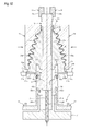
- Fig. 15 is a sectional view showing the molding mold in the aforementioned related art.
- a molding mold 100 has an inner mold 110 and a pair of left and right outer molds 120.
- the inner mold 110 includes a plurality of split molds 113 disposed radially along the outer circumferential surface of a core shaft 112 inserted into a set ring 111.
- the outer molds 120 form a cavity 130 among the outer molds 120 and the inner mold 110.
- the inner mold 110 After injection-molding a molded body W for a constant velocity joint boot, the inner mold 110 is moved onto a base 201 of a disassembling/assembling machine 200 together with the moldedbodyW, as shown in Fig. 16 .
- the disassembling/assembling machine 200 disassembles the set ring 111, the core shaft 112 and the split molds 113 in the inner mold 110, extracts the molded body W, and then assembles the inner mold 110 again.
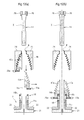
- Fig. 17(a) and Fig. 17(b) are sectional views showing a procedure in which the inner mold 110 is disassembled by the disassembling/assembling machine 200.
- retention members 202 are first engaged with the set ring 111 to retain the set ring 111 on the base 201, as shown in Fig. 16 .
- the molded body W is held by a pair of first clamps 204 after the split molds 113 are lifted up above the set ring 111 respectively by a plurality of support members 203 each formed into a sectionally L shape.
- the core shaft 112 is lifted up above the split molds 113 by a pair of second clamps 205.
- the support members 203 are pushed inward radially to move the split molds 113 inward radially, respectively as shown in Fig. 17(b) .
- the split molds 113 can be separated from the molded body W.
- Patent Reference 1 JP-A-2009-228871
- Each support member 203 in the related art is formed into a sectionally L shape. Therefore, the following problem may arise when the support member 203 is pushed inward radially as shown in Fig. 17(b) . That is, when the support member 203 is pushed inward radially, a reaction force of the split mold 113 acts on a vertical portion 203a of the support member 203. Accordingly, as shown in Fig. 18 , a large bending moment occurs at a support point P of the vertical portion 203a. Thus, when the operation of pushing the support member 203 inward radially is carried out repeatedly, the vertical portion 203a of the support member 203 may be bent as shown by the alternate long and two short dashes line in Fig. 18 , so that the split mold 113 cannot be separated from the molded body W.
- An object of the invention is to provide an apparatus for manufacturing a constant velocity joint boot and a method of manufacturing the same, capable of suppressing deformation of support members supporting split molds when the split molds are separated from a molded body.
- An apparatus for manufacturing a constant velocity joint boot includes a molding mold that injection-molds a molded body for the constant velocity joint boot using an inner mold and an outer mold, the inner mold including a plurality of split molds disposed radially along an outer circumferential surface of a core shaft extending vertically, the outer mold forming a cavity between the inner mold and the outer mold, the split molds of the inner mold being moved inward radially while being supported in a state where the core shaft is separated from the inner mold after the molded body is injection-molded, so that the split molds is separated from the molded body, characterized in that: the split molds include extension portions extending downward under the molded body; concave portions recessed inward radially are formed in outer circumferential surfaces of the extension portions; and rod-like support members include: distal end portions inserted into the concave portions of the extension portions to support the split molds; and step surfaces abutting against the outer circumferential surfaces of the extension portions in a state where the split molds
- a method of manufacturing a constant velocity joint boot is characterized by including, in this order, the steps of: injection-molding a molded body for the constant velocity joint boot using an inner mold and an outer mold, the inner mold including a plurality of split molds disposed radially along an outer circumferential surface of a core shaft extending vertically, the outer mold forming a cavity between the inner mold and the outer mold; separating the core shaft from the inner mold in a state where the inner mold and the outer mold have been separated; inserting distal endportions of rod-like support members into concave portions to thereby support the split molds, the concave portions formed to be recessed inward radially from outer circumferential surfaces of extension portions extending downward under the molded body in the split molds; and pushing the support members inward radially to thereby separate the split molds from the molded body in a state where step surfaces formed in the support members have been brought into contact with the outer circumferential surfaces of the extension portions.
- the distal end portions of the rod-like support members are inserted into the concave portions formed in the extension portions of the split molds so that the split molds can be supported. Then, in the state where the step surfaces of the support members have been brought into contact with the outer circumferentialsurfacesofthe extension portions, the support members are pushed inward radially so that the split molds can be moved inward radially.
- reaction forces from the split molds act on the rod-like support members.
- most of the reaction forces act as compression stress in the longitudinal directions of the support members respectively. It is therefore possible to reduce occurrence of a bending moment in comparison with support members each formed into an L shape in the related art. Thus, deformation of the support members can be suppressed when the split molds are separated from the molded body for the constant velocity joint boot.
- the concave portions and the distal end portions of the support members are formed into sectionally T shapes. In this case, when the distal end portions of the support members are inserted into the concave portions, the split molds can be supported stably.
- the outer circumferential surfaces of the extension portions are made of a magnetic substance, and parts or all of the step surfaces are formed of permanent magnets that can be attracted to the outer circumferential surfaces of the extension portions by magnetic forces.
- the step surfaces of the support members can be fixed to the outer circumferential surfaces of the extension portions by the magnetic force. It is therefore possible to support the split molds more stably.
- deformation of the support members can be suppressed when the split molds are separated from the molded body for the constant velocity joint boot.
- Fig. 1 is a sectional view showing a part of an apparatus for manufacturing a constant velocity joint boot according to an embodiment of the invention.
- This manufacturing apparatus has a molding mold 1 for injection-molding a molded body W for a constant velocity joint boot 9.
- the molding mold 1 is constituted by a pair of left and right outer molds 11, an inner mold 12 disposed inside the outer molds 11, and a lower mold 13 disposed under the outer molds 11.
- the constant velocity joint boot 9 is constituted by a large diameter portion 9a and a small diameter portion 9c, which are formed into cylindrical shapes, and a bellows-like portion 9b connecting the large diameter portion 9a and the small diameter portion 9c with each other.
- the outer molds 11 are disposed movably in a horizontal direction (left/right direction in Fig. 1 ) on the upper surface of the lower mold 13. Mold surfaces 11a corresponding to the shapes of outer circumferential surfaces of the large diameter portion 9a, the bellows-like portion 9b and the small diameter portion 9c in the constant velocity joint boot 9 are formed in the inner side surfaces of the outer molds 11. A cavity 19b is formed between the mold surfaces 11a and mold surfaces 152a to 152h (which will be described later) of the inner mold 12. In addition, an introduction path 11b for introducing a molding material into the cavity 19b and so on is formed in the outer molds 11.
- elastomer such as thermoplastic polyester elastomer or thermoplastic polyolefinic elastomer
- a recess portion 13a is formed in the upper surface of the lower mold 13.
- a mounting hole 13b is formed in the recess portion 13a.
- the inner mold 12 is constituted by a core shaft 14 disposed with its axis X extending vertically, a plurality of split molds 15a to 15h (see Fig. 2 ) disposed on the radially outer side of the core shaft 14, and a set ring 16 disposed under the split molds 15a to 15h.
- the core shaft 14 includes a solid columnar member, which has a circular outer circumferential surface 14a.
- An annular protrusion portion 14b (pressing means) protruding to the radially outside is formed integrally with the outer circumference of the upper end portion of the core shaft 14.
- the lower surface of the protrusion portion 14b can abut against the upper surfaces of the split molds 15a to 15h so as to press down the upper end portions of the split molds 15a to 15h (also see Fig. 2 ).
- the core shaft 14 in the embodiment is formed of a solid columnar member, the core shaft 14 may be formed of a hollow cylindrical member.
- the pressing means includes the protrusion portion 14b provided to protrude on the core shaft 14, the pressing means may be provided as a separate body from the core shaft 14.
- a mold surface 14c corresponding to the shape of the inner circumferential surface of the small diameter portion 9c in the constant velocity joint boot 9 is formed in the outer circumferential surface of the protrusion port ion 14b.
- a cavity 19a is formed between the mold surface 14c and the mold surfaces 11a of the outer molds 11.
- a plurality of concave lock portions 14d are formed in the outer circumference of the lower end portion of the core shaft 14 integrallytherewith.
- Apulling-inmeans 10 forpulling the lower end portion of the core shaft 14 downward can be locked in the lock portions 14d.
- the pulling-in means 10 includes a plurality of hook portions 10a, which can be locked in the lock portions 14d respectively.
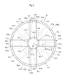
- Fig. 2 is a schematic plan view showing the inner mold 12.
- the inner mold 12 includes, as the aforementioned plurality of split molds 15a to 15h, first to fourth split molds 15a to 15d formed into rectangular shapes in planar view respectively, and fifth to eighth split molds 15e to 15h formed into fan shapes in planar view respectively.
- the split molds 15a to 15h are disposed radially along the outer circumferential surface 14a of the core shaft 14 around the axis X of the core shaft 14.
- the split molds 15a to 15d that are rectangular in planar view and the split molds 15e to 15h that are fan-shaped in planar view are disposed circumferentially alternately so as to be formed into a circle as a whole in planar view.
- inner circumferential surfaces 151a to 151h of the split molds 15a to 15h are formed into arcs respectively along the outer circumferential surface 14a of the core shaft 14.
- Mold surfaces 152a to 152h corresponding to the shapes of the inner circumferential surfaces of the large diameter portion 9a and the bellows-like portion 9b in the constant velocity joint boot 9 are formed in the outer circumferential surfaces of the split molds 15a to 15h respectively.
- Extension portions 155a to 155h extending downward under the molded body W are formed in the lower portions of the split molds 15a to 15h integrally therewith respectively.
- the extension portions 155a to 155h are made of a magnetic substance, and inserted into the recess portion 13a of the lower mold 13.
- Engagement grooves 153a to 153h to which the upper end portion of the set ring 16 is inserted are formed in the lower surfaces of the extension portions 155a to 155h respectively.
- the engagement grooves 153a to 153h are formed into an annular shape as a whole in the state where the split molds 15a to 15h have been disposed into a circle in planar view as shown in Fig. 2 .
- An annular engaged surface 15i is formed in the inner side surfaces of the engagement grooves 153a to 153h so as to be formed as a tapered surface whose diameter is reduced gradually as it goes from top to bottom.
- the outer side surfaces of the engagement grooves 153a to 153h are formed to face the outer circumferential surface of the set ring 16 in the state where the upper end portion of the set ring 16 has been inserted into the engagement grooves 153a to 153h.
- Concave portions 154a to 154h are formed to be recessed inward radially in the outer circumferential surfaces of the extension portions 155a to 155h respectively so that distal end portions 232a to 232h of first to eighth support members 23a to 23h, which will be described later, can be inserted into the concave portions 154a to 154h respectively.
- inward radially may include not only a radial direction extending toward a center point on the axis X but also a direction extending toward a point slightly displaced from the center point.
- the concave portions 154a to 154h in the embodiment extend radially toward the center point. Incidentally the concave portions 154a to 154h have similar configurations. Therefore, only the concave portion 154a will be described in the embodiment.
- Fig. 3 is a sectional view from the arrow direction A-A in Fig. 2 , showing the concave portion 154a.
- the concave portion 154a includes a groove whose lower end is open in the lower surface of the extension portion 155a, and the concave portion 154a is formed into a sectionally T shape.
- the radially outer end of the concave portion 154a is open in the outer circumferential surface of the extension portion 155a
- the radially inner end of the concave portion 154a is open in the outer circumferential surface of the engagement groove 153a.
- the distal end portion 232a of the first support member 23a can be inserted into the concave portion 154a so as to extend from its radially outer end toward its radially inner side.
- the set ring 16 is formed into a cylindrical shape as a whole, and removably attached into the mounting hole 13b of the lower mold 13.
- the lower portion of the core shaft 14 is inserted into the set ring 16 movably vertically on the inner circumferential surface 16a thereof.
- an annular engagement surface 16b is formed on the inner circumferential side of the upper end portion of the set ring 16 so that the lower end portions of the split molds 15a to 15h can be introduced and engaged to the annular engagement surface 16b in the state where the upper end portion of the set ring 16 has been inserted into the engagement grooves 153a to 153h.
- the engagement surface 16b is formed to have a larger diameter than the inner circumferential surface 16a, and composed of a tapered surface whose diameter is reduced gradually as it goes from top to bottom.
- An annular groove 16c is formed in the outer circumference of the upper end portion of the set ring 16.
- An O-ring 17 is attached to the annular groove 16c so as to be brought into pressure contact with the outer side surfaces (opposed surfaces) of the engagement grooves 153a to 153h of the split molds 15a to 15h.
- Aplurality of first lock grooves 16d are formed under the annular groove 16c in the outer circumference of the set ring 16 so that a plurality of claw portions 3a (see Fig. 4 ) of a chuck 3 can be locked in the first lock grooves 16d respectively.
- a plurality of second lock grooves 16e are formed in the outer circumference of the lower end portion of the set ring 16 so that lock claws 22c of retention members 22, which will be described later, can be locked in the second lock grooves 16e respectively.
- Fig. 4 is a sectional view showing a state where the inner mold 12 is removed from the lower mold 13 after injection molding.
- a plurality (for example, four) of ejectors 18 formed into rod-like shapes are disposed movably vertically to push up the lower surface of the set ring 16 attached into the mounting hole 13b.
- the lower surface of the set ring 16 can be pushed up when the ejectors 18 are moved upward after the paired outer molds 11 located in Fig. 1 are moved to the opposite left and right sides to thereby leave the inner mold 12.
- the core shaft 14 the split molds 15a to 15h and the molded body W move upward together with the set ring 16 so that the inner mold 12 can be separated upward from the lower mold 13.
- Fig. 5 is a sectional view showing the disassembling/assembling machine 2.
- the disassembling and assembling machine 2 is to disassemble the inner mold 12 moved from the molding mold 1 by the chuck 3 and extract the molded body W from the inner mold 12, and to assemble the disassembled inner mold 12 again.
- the disassembling and assembling machine 2 has a base 21, a pair of retention members 22, first to eighth support members 23a to 23h (see Fig. 7 ), a pair of first clamps 24 (see Fig. 9 ), an ejector 25 (see Fig. 10 ), and a pair of second clamps 26 (see Fig. 10 ).
- the base 21 includes a cylindrical portion 21a, which can support the lower end portion of the core shaft 14 inserted thereto in the state where the axis X of the core shaft 14 extends vertically.
- the upper surface of the cylindrical portion 21a abuts against the lower surface of the set ring 16 to thereby restrict the downward movement of the core shaft 14.
- a through hole 21b is formed in the bottom portion of the cylindrical portion 21a so that the ejector 25 can be inserted to the through hole 21b from below the base 21.
- the pair of retention members 22 retain the set ring 16 in the state where the set ring 16 has been disposed on the cylindrical portion 21a of the base 21.
- the retention members 22 are disposed above the base 21 movably in a horizontal direction (left/right direction of Fig. 5 ).
- the distal end portion of each retention member 22 is formed into a sectionally L shape, which includes a horizontal portion 22a and a vertical portion 22b.
- Lock claws 22c are formed in the upper end portions of the vertical portions 22b so as to be locked in the second lock grooves 16e of the set ring 16 respectively.
- the disassembling/assembling machine 2 further includes a cutting means (not shown) for cutting a runner portion 4 (the crosshatched portion in Fig. 5 ) molded in the introduction path 11b of the outer molds 11 in the state of Fig. 5 .
- Fig. 6 is a sectional view showing the operating state of the first to eighth support members 23a to 23h in the disassembling/assembling machine 2.
- the first to eighth support members 23a to 23h support the respective split molds 15a to 15h that have been separated from the set ring 16.
- Each support member 23a to 23h can move vertically and horizontally individually, for example, by a cylinder (not shown).
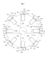
- Fig. 7 is a plan view of the first to eighth support members 23a to 23h.
- the first to eighth support members 23a to 23h are disposed radially around the axis X.
- each support member 23a to 23h is formed into a rod-like shape, which includes a body portion 231a to 231h, a distal end portion 232a to 232h formed at the distal end of the body portion 231a to 231h integrally therewith, and a step surface 234a to 234h.
- the first to eighth support members 23a to 23h have similar configurations. Therefore, only the first support member 23a will be described in the embodiment.
- Fig. 8 (a) and Fig. 8(b) show the support member 23a.
- Fig. 8(a) is a sectional view from the arrow direction B-B in Fig. 7
- Fig. 8(b) is a sectional view from the arrow direction C-C in Fig. 7 .
- the body portion 231a to 231h of the support member 23a is formed into a sectionally circular shape
- the distal end portion 232a of the support member 23a is formed into a sectionally T shape.
- the distal end portion 232a is formed to be slightly smaller than the sectional shape of the concave portion 154a so that the distal end portion 232a can be removably inserted into the concave portion 154a of the extension portion 155a (see Fig. 3 ).
- the longitudinal (radial) length of the distal end portion 232a is formed to be slightly shorter than the radial length of the concave portion 154a (see Fig. 6 ).
- a permanent magnet 233a formed into an annular plate-like shape is buried in the distal end portion of the body portion 231a.
- a distal end surface 233a1 of the permanent magnet 233a and a distal end surface 231a1 of the body portion 231a are formed to be flush with each other so as to form the step portion 234a.
- the step portion 234a abuts against the outer circumferential surface of the extension portion 155a in the state where the distal end portion 232a has supported the first split mold 15a, as described above.
- a part (end surface 233a1) of the step surface 234a is attracted and fixed to the outer circumferential surface of the extension portion 155a due to a magnetic force of the permanent magnet 233a.
- Fig. 9 is a sectional view showing an operating state of the first clamps 24 of the disassembling/assembling machine 2.
- the pair of first clamps 24 retain the molded body W when the split molds 15a to 15h are lifted up by the support members 23a to 23h respectively.
- the first clamps 24 are disposed movably horizontally (left/right direction of Fig. 9 ) and vertically.
- Retention surfaces 24a corresponding to the shapes of the outer circumferential surfaces of the large diameter portion 9a, the bellows-like portion 9b and the small diameter portion 9c in the molded body W are formed in the inner side surfaces of the first clamps 24 respectively. Due to the retention surfaces 24a, the outer circumferential surface of the molded body W can be retained in the state where the outer circumferential surface of the molded body W has been nipped from the opposite left and right sides.
- Fig. 10 is a sectional view showing the operating state of the ejector 25 and the second clamps 26 in the disassembling/assembling machine 2.
- the ejector 25 is to push up the lower surface of the core shaft 14 inserted into the cylindrical portion 21a of the base 21, and the ejector 25 includes a rod-like member that can be inserted into the through hole 21b of the base 21 from below.
- the pair of second clamps 26 are to pull up the upper end portion of the core shaft 14 pushed up by the ejector 25 while holding the upper end portion of the core shaft 14.
- the second clamps 26 are disposed movably vertically above the first clamps 24.
- Engagement portions 2 6a are formed in the distal endportions of the second clamps 26 so as to be engaged with the upper end corner portions of the protrusion portion 14b of the core shaft 14 respectively. Due to the engagement portions 26a, the upper end portion of the core shaft 14 can be retained while being nipped from the opposite left and right sides.
- the lower endportion of the core shaft 14 pulled in downward is retained in the molding mold 1 as it is.
- the protrusion portion 14b of the upper end portion of the core shaft 14 presses the split molds 15a to 15h of the inner mold 12 downward.
- the lower end portions of the split molds 15a to 15h move toward the axis X along the engagement surface 16b, which is a tapered surface of the set ring 16, so as to engage with the engagement surface 16b.
- the split molds 15a to 15h can be retained in the state where circumferentially adjacent ones of the split molds 15a to 15h have been brought into close contact with each other.
- the molded body W for the constant velocity joint boot 9 is injection-molded using the paired outer molds 11 and the inner mold 12 in the molding mold 1. Specifically, a molding material is introduced sequentially into the respective cavities 19a and 19b from the introduction path 11b of the outer molds 11 so as to injection-mold the molded body W. On that occasion, the runner portion 4 (see Fig. 4 ) is molded integrally with the molded body W in the introduction path 11b. After the injection molding of the molded body W, the aforementioned tool is removed from the lock portions 14d of the core shaft 14 so as to release the core shaft 14 from being pulling in downward.
- the paired outer molds 11 are moved to the opposite left and right sides in the state of Fig. 1 to be thereby separated from the inner mold 12, and the inner mold 12 is then separated from the lower mold 13.
- the lower surface of the set ring 16 is pushed up by the ejectors 18 so as to move the set ring 16 upward above the lower mold 13 together with the core shaft 14, the split molds 15a to 15h and the molded body W.
- the claw portions 3a of the chuck 3 are locked in the first lock grooves 16d of the set ring 16 so as to lift up the set ring 16.
- the inner mold 12 can be separated from the lower mold 13.
- the inner mold 12 is moved to the disassembling/assembling machine 2 together with the molded body W by the chuck 3.
- the lower end portion of the core shaft 14 of the inner mold 12 is inserted into the cylindrical portion 21a of the base 21, and the paired retention members 22 are locked in the second lock grooves 16e of the set ring 16.
- the set ring 16 is retained on the base 21.
- the runner portion 4 molded integrally with the molded body W is cut out.
- the first to eighth support members 23a to 23h are moved in the illustrated arrow directions respectively, and the distal end portions 232a to 232h of the first to eighth support members 23a to 23h are inserted into the concave portions 154a to 154h of the split molds 15a to 15h respectively.
- the distal end portions 232a to 232h are inserted until the step surfaces 234a to 234h abut against the outer circumferential surfaces of the extension portions 155a to 155h of the split molds 15a to 15h and the permanent magnets 233a to 233h are attracted onto the outer circumferential surfaces due to magnetic forces respectively.
- the split molds 15a to 15h can be supported by the first to eighth support members 23a to 23h respectively.
- the first to eighth support members 23a to 23h are moved upward to lift up the split molds 15a to 15h respectively.
- the inner mold 12 wants to be lifted up as a whole.
- the split molds 15a to 15h and the core shaft 14 move upward relatively to the set ring 16 as shown in Fig. 6 because the set ring 16 is retained on the base 21 by the retention members 22. In this manner, the split molds 15a to 15h can be separated from the set ring 16 together with the molded body W.
- the paired first clamps 24 are moved in the illustrated arrow directions respectively so as to hold and retain the molded body W from the opposite left and right sides.
- the ejector 25 is inserted into the through hole 21b of the base 21 from below so as to push the lower surface of the core shaft 14.
- the set ring 16 is retained by the retention members 22 while vertical movement of the split molds 15a to 15h is restricted by the first clamps 24 through the molded body W.
- the upper end portion of the core shaft 14 protrudes above the first clamps 24.
- the upper end portion of the core shaft 14 is kept to be nipped from the opposite left and right sides by the paired second clamps 26 while the second clamps 26 are moved upward.
- the core shaft 14 can be separated from the set ring 16 and the split molds 15a to 15h.
- the first clamps 24 are also being moved upward while holding the molded body W.
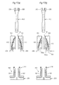
- Fig. 11(a) to Fig. 13(b) are sectional views of the disassembling/assembling machine 2, showing the manufacturing process of the aforementioned manufacturing apparatus.
- the split molds 15a to 15h are separated from the molded body W after the core shaft 14, the set ring 16 and the split molds 15a to 15h are separated vertically.
- the support members 23a to 23h are pushed inward radially so that the split molds 15a to 15h can be pressed inward radially by the step surfaces 234a to 234h respectively.
- the split molds 15a to 15h are displaced horizontally toward their center, that is, toward the axis X.
- the split molds 15a to 15h are moved to positions where the mold surfaces 152a to 152h of the split molds 15a to 15h cannot interfere with the bellows-like portion 9b of the molded body W respectively. In this manner, the split molds 15a to 15h can be separated from the molded body W. After that, as shown in Fig. 12(a) , the support members 23a to 23h are moved downward to pull out the split molds 15a to 15h downward under the molded body W respectively.
- Fig. 14(a), Fig. 14(b), Fig. 14 (c) and Fig. 14 (d) are plan views showing the detailed procedure to disassemble the inner mold 12.
- the first to fourth split molds 15a to 15d each having a rectangular shape in planar view are separated from the molded body W.
- the first split mold 15a is displaced horizontally toward the axis X to be thereby brought into a state shown in Fig. 14(b) .
- the first split mold 15a is pulled out downward under the molded body W.
- the third split mold 15c, the second split mold 15b and the fourth split mold 15d are separated from the molded body W in this order, so as to be brought into a state shown in Fig. 14(c) .
- the remaining fifth to eighth split molds 15e to 15h each having a fan shape in planar view are separated from the molded body W.
- the fifth split mold 15e is displaced horizontally toward the axis X to be thereby brought into a state shown in Fig. 14(d) .
- the fifth split mold 15e is pulled out downward under the molded body W.
- the seventh split mold 15g, the sixth split mold 15f and the eighth split mold 15h are separated from the molded body W in this order.
- the split molds 15a to 15h pulled out under the molded body W are moved horizontally in opposite directions to the aforementioned directions in which they were displaced horizontally by the support members 23a to 23h respectively, and then moved downward.
- the lower end portions of the split molds 15a to 15h are introduced into the inner circumferential side of the upper end portion of the set ring 16 while their engaged surfaces 15i move along the engagement surface 16b of the set ring 16, as shown in Fig. 12 (b) .
- the split molds 15a to 15h are introduced into the set ring 16, the split molds 15a to 15h are supported by the support members 23a to 23h respectively until the completion of the downward movement of the core shaft 14, which will be described later.
- the core shaft 14 held by the second clamps 26 is moved downward.
- the lower end portion of the core shaft 14 is inserted to the center portion of the split molds 15a to 15h formed into a circular shape in planar view, the inner circumferential surface of the set ring 16 and the inner circumferential surface of the cylindrical portion 21a of the base 21 sequentially from above.
- the lower surface of the protrusion portion 14b of the core shaft 14 abuts against the upper surfaces of the split molds 15a to 15h so as to press the split molds 15a to 15h downward simultaneously.
- the lower endportions of the split molds 15a to 15h are introduced to and engaged with the engagement surface 16b which is a tapered surface of the set ring 16.
- the split molds 15a to 15h are engaged while moving toward the axis X as they move downward due to the engagement surface 16b.
- circumferentially adjacent ones of the split molds 15a and 15h can be brought into close contact with each other.
- the split molds 15a to 15h are brought into a circular shape as a whole in planar view so that the inner mold 12 can be restored to its original state.
- the support members 23a to 23h are moved outward radially against the attraction forces of the permanent magnets 233a to 233h respectively, and the distal end portions 232a to 232h of the support members 23a to 23h are pulled out from the concave portions 154a to 154h respectively.
- the split molds 15a to 15h are released from being supported by the support members 23a to 23h respectively (seeFig. 13(b)).
- the retention members 22 are moved outward radially to release the set ring 16 from being retained.
- the claw portions 3a of the chuck 3 are locked in the first lock grooves 16d of the set ring 16 again to lift up the inner mold 12 as a whole and return the inner mold 12 to its predetermined position in the molding mold 1 as shown in Fig. 4 (where the illustrated molded body W has been removed) .
- the engagement of the chuck 3 is released while the ejectors 18 are moved downward to mount the inner mold 12 into the mounting hole 13b of the lower mold 13 as shown in Fig. 1 .
- the distal end portions 232a to 232h of the first to eighth support members 23a to 23h each having a rod-like shape are inserted into the concave portions 154a to 154h formed in the extension portions 155a to 155h of the split molds 15a to 15h respectively.
- the split molds 15a to 15h can be supported by the first to eighth support members 23a to 23h respectively.
- the first to eighth support members 23a to 23h are pushed inward radially so that the split molds 15a to 15h can be moved inward radially.
- the reaction forces of the split molds 15a to 15h act on the first to eighth support members 23a to 23h each having a rod-like shape, respectively.
- most of the reaction forces act as compression stress in the longitudinal directions of the first to eighth support members 23a to 23h. It is therefore possible to reduce a bending moment in comparison with support members each formed into an L shape in the related art. As a result, the first to eighth support members 23a to 23h can be suppressed from being deformed when the split molds 15a to 15h are separated from the molded body W for the constant velocity joint boot 9.
- the concave portions 154a to 154h of the split molds 15a to 15h and the distal end portions 232a to 232h of the first to eighth support members 23a to 23h are formed into sectionally T shapes respectively. Accordingly, when the distal end portions 232a to 232h are inserted into the concave portions 154a to 154h, the split molds 15a to 15h can be supported in a stable state.
- the permanent magnets 233a to 233h constituting parts of the step surfaces 234a to 234h of the first to eighth support members 23a to 23h can be fixed to the outer circumferential surfaces of the extension portions 155a to 155h due to magnetic forces respectively. Accordingly, the split molds 15a to 15h can be supported in a more stable state.
- the extension portions are formed in all the split molds 15a to 15h in the aforementioned embodiment. However, it will go well if such an extension portion is formed in at least one of the split molds 15a to 15h.
- the step surfaces 234a to 234h are constituted by the end surfaces of the permanent magnets 233a to 233h and the end surfaces of the body portions 231a to 231h respectively in the embodiment. However, each step surface 234a to 234h may be constituted by only one of the two end surfaces.
- the extension portions 155a to 155h are entirely made of a magnetic substance in the embodiment. However, it will go well if at least the outer circumferential of each extension portion 155a to 155h is made of a magnetic substance.
- each of the concave portions 154a to 154h of the split molds 15a to 15h and the distal end portions 232a to 232h of the first to eighth support members 23a to 23h is formed into a sectionally T shape in the embodiment.
- the shape may be any other sectional shape as long as it can support the split mold 15a to 15h.
- the concave portions 154a to 154h include grooves that are open in the lower surfaces of the extension portions 155a to 155h respectively. However, they may be holes that are not open in the lower surfaces of the extension portions 155a to 155h.
- an apparatus for manufacturing a constant velocity joint boot and a method of manufacturing the same, capable of suppressing deformation of support members supporting split molds when the split molds are separated from a molded body.
Landscapes
- Engineering & Computer Science (AREA)
- General Engineering & Computer Science (AREA)
- Mechanical Engineering (AREA)
- Manufacturing & Machinery (AREA)
- Moulds For Moulding Plastics Or The Like (AREA)
- Diaphragms And Bellows (AREA)
- Sealing Devices (AREA)
Abstract
Description
- The present invention relates to an apparatus for manufacturing a constant velocity joint boot and a method of manufacturing the same.
- For example, in a vehicle such as an automobile, a constant velocity joint is used for transmitting torque to driving wheels moving up/down to follow a road surface. A constant velocity joint boot made of synthetic resin or like is mounted on the constant velocity joint in order to protect the constant velocity joint from external muddy water or dust and to hold lubricating grease supplied to the constant velocity joint. The constant velocity joint boot is typically constituted by a cylindrical large diameter portion, a cylindrical small diameter portion and a bellows-like portion connecting the large diameter portion and the small diameter portion with each other, and formed by a blow molding method (for example, see Patent Reference 1).
- In the aforementioned blow molding method, molten resin formed into a bag-like shape is set in an outer mold, and the bag-like molten resin is expanded and pressed onto the outer mold by air blow to be thereby molded without using an inner mold. For this reason, in the blow molding method, the inner circumferential surface of the constant velocity joint boot cannot be formed accurately. Therefore, the blow molding method cannot be regarded as an optimal method for forming the constant velocity joint boot requiring an accurate bellows structure.
- Therefore, the present applicant has already proposed a related art for injection-molding a constant velocity joint boot using a molding mold including an inner mold and an outer mold forming a cavity between the inner mold and the outer mold (Japanese Patent Application No.
2012-257532 -
Fig. 15 is a sectional view showing the molding mold in the aforementioned related art. As shown inFig. 15 , amolding mold 100 has aninner mold 110 and a pair of left and rightouter molds 120. Theinner mold 110 includes a plurality ofsplit molds 113 disposed radially along the outer circumferential surface of acore shaft 112 inserted into aset ring 111. Theouter molds 120 form acavity 130 among theouter molds 120 and theinner mold 110. - After injection-molding a molded body W for a constant velocity joint boot, the
inner mold 110 is moved onto abase 201 of a disassembling/assemblingmachine 200 together with the moldedbodyW, as shown inFig. 16 . The disassembling/assemblingmachine 200 disassembles theset ring 111, thecore shaft 112 and thesplit molds 113 in theinner mold 110, extracts the molded body W, and then assembles theinner mold 110 again. -
Fig. 17(a) and Fig. 17(b) are sectional views showing a procedure in which theinner mold 110 is disassembled by the disassembling/assemblingmachine 200. When theinner mold 110 is disassembled,retention members 202 are first engaged with theset ring 111 to retain theset ring 111 on thebase 201, as shown inFig. 16 . Next as shown inFig. 17(a) , the molded body W is held by a pair offirst clamps 204 after thesplit molds 113 are lifted up above theset ring 111 respectively by a plurality ofsupport members 203 each formed into a sectionally L shape. In this state, thecore shaft 112 is lifted up above thesplit molds 113 by a pair ofsecond clamps 205. Next, in this state, thesupport members 203 are pushed inward radially to move thesplit molds 113 inward radially, respectively as shown inFig. 17(b) . Thus, thesplit molds 113 can be separated from the molded body W. - Patent Reference 1:
JP-A-2009-228871 - Each
support member 203 in the related art is formed into a sectionally L shape. Therefore, the following problem may arise when thesupport member 203 is pushed inward radially as shown inFig. 17(b) . That is, when thesupport member 203 is pushed inward radially, a reaction force of thesplit mold 113 acts on avertical portion 203a of thesupport member 203. Accordingly, as shown inFig. 18 , a large bending moment occurs at a support point P of thevertical portion 203a. Thus, when the operation of pushing thesupport member 203 inward radially is carried out repeatedly, thevertical portion 203a of thesupport member 203 may be bent as shown by the alternate long and two short dashes line inFig. 18 , so that thesplit mold 113 cannot be separated from the molded body W. - The invention has been developed in consideration of the foregoing problem. An object of the invention is to provide an apparatus for manufacturing a constant velocity joint boot and a method of manufacturing the same, capable of suppressing deformation of support members supporting split molds when the split molds are separated from a molded body.
- An apparatus for manufacturing a constant velocity joint boot according to the invention includes a molding mold that injection-molds a molded body for the constant velocity joint boot using an inner mold and an outer mold, the inner mold including a plurality of split molds disposed radially along an outer circumferential surface of a core shaft extending vertically, the outer mold forming a cavity between the inner mold and the outer mold, the split molds of the inner mold being moved inward radially while being supported in a state where the core shaft is separated from the inner mold after the molded body is injection-molded, so that the split molds is separated from the molded body, characterized in that: the split molds include extension portions extending downward under the molded body; concave portions recessed inward radially are formed in outer circumferential surfaces of the extension portions; and rod-like support members include: distal end portions inserted into the concave portions of the extension portions to support the split molds; and step surfaces abutting against the outer circumferential surfaces of the extension portions in a state where the split molds are supported by the distal end portions.
- In addition, a method of manufacturing a constant velocity joint boot is characterized by including, in this order, the steps of: injection-molding a molded body for the constant velocity joint boot using an inner mold and an outer mold, the inner mold including a plurality of split molds disposed radially along an outer circumferential surface of a core shaft extending vertically, the outer mold forming a cavity between the inner mold and the outer mold; separating the core shaft from the inner mold in a state where the inner mold and the outer mold have been separated; inserting distal endportions of rod-like support members into concave portions to thereby support the split molds, the concave portions formed to be recessed inward radially from outer circumferential surfaces of extension portions extending downward under the molded body in the split molds; and pushing the support members inward radially to thereby separate the split molds from the molded body in a state where step surfaces formed in the support members have been brought into contact with the outer circumferential surfaces of the extension portions.
- According to the apparatus for manufacturing a constant velocity joint boot and the method of manufacturing the same according to the invention, the distal end portions of the rod-like support members are inserted into the concave portions formed in the extension portions of the split molds so that the split molds can be supported. Then, in the state where the step surfaces of the support members have been brought into contact with the outer circumferentialsurfacesofthe extension portions, the support members are pushed inward radially so that the split molds can be moved inward radially. On that occasion, reaction forces from the split molds act on the rod-like support members. However, most of the reaction forces act as compression stress in the longitudinal directions of the support members respectively. It is therefore possible to reduce occurrence of a bending moment in comparison with support members each formed into an L shape in the related art. Thus, deformation of the support members can be suppressed when the split molds are separated from the molded body for the constant velocity joint boot.
- It is preferable that the concave portions and the distal end portions of the support members are formed into sectionally T shapes. In this case, when the distal end portions of the support members are inserted into the concave portions, the split molds can be supported stably.
- It is preferable that the outer circumferential surfaces of the extension portions are made of a magnetic substance, and parts or all of the step surfaces are formed of permanent magnets that can be attracted to the outer circumferential surfaces of the extension portions by magnetic forces. In this case, the step surfaces of the support members can be fixed to the outer circumferential surfaces of the extension portions by the magnetic force. It is therefore possible to support the split molds more stably.
- According to the apparatus for manufacturing a constant velocity joint boot and the method of manufacturing the same according to the invention, deformation of the support members can be suppressed when the split molds are separated from the molded body for the constant velocity joint boot.
-
- [
Fig. 1] Fig. 1 is a sectional view showing a part of an apparatus for manufacturing a constant velocity joint boot according to an embodiment of the invention. - [
Fig. 2] Fig. 2 is a schematic plan view showing an inner mold of a molding mold of the aforementioned manufacturing apparatus. - [
Fig. 3] Fig. 3 is a sectional view from the arrow direction A-A inFig. 2 . - [
Fig. 4] Fig. 4 is a sectional view showing a state in which the inner mold is removed from a lower mold of the molding mold. - [
Fig. 5] Fig. 5 is a sectional view showing a disassembling/assembling machine of the aforementioned manufacturing apparatus. - [
Fig. 6] Fig. 6 is a sectional view showing a state in which support members of the aforementioned disassembling/assembling machine are in operation. - [
Fig. 7] Fig. 7 is a plan view of the aforementioned support members. - [
Figs. 8] Fig. 8 (a) is a sectional view from the arrow direction B-B inFig. 7 , andFig. 8 (b) is a sectional view from the arrow direction C-C inFig. 7 . - [
Fig. 9] Fig. 9 is a sectional view showing a state in which first clamps of the aforementioned disassembling/assembling machine are in operation. - [
Fig. 10] Fig. 10 is a sectional view showing a state in which second clamps of the aforementioned disassembling/assembling machine are in operation. - [
Figs. 11] Fig. 11 (a) and Fig. 11 (b) are sectional views of the disassembling/assembling machine, showing a manufacturing process of the aforementioned manufacturing apparatus. - [
Figs. 12] Fig. 12 (a) and Fig. 12 (b) are sectional views of the disassembling/assembling machine, showing the manufacturing process of the aforementioned manufacturing apparatus. - [
Figs. 13] Fig. 13 (a) and Fig. 13 (b) are sectional views of the disassembling/assembling machine, showing the manufacturing process of the aforementioned manufacturing apparatus. - [
Figs. 14] Fig. 14(a), Fig. 14(b), Fig. 14 (c) and Fig. 14 (d) are plan views showing a procedure in which the inner mold is disassembled by the aforementioned disassembling/assembling machine. - [
Fig. 15] Fig. 15 is a sectional view showing a molding mold for a constant velocity joint boot in a related art. - [
Fig. 16] Fig. 16 is a sectional view showing a disassembling/assembling machine in the related art. - [
Figs. 17] Fig. 17 (a) and Fig. 17 (b) are sectional views showing a procedure in which an inner mold is disassembling by the disassembling/assembling machine in the related art. - [
Fig. 18] Fig. 18 is a sectional view showing a support member of the disassembling/assembling machine in the related art. - Next, a preferred embodiment of the invention will be described with reference to the accompanying drawings.
-
Fig. 1 is a sectional view showing a part of an apparatus for manufacturing a constant velocity joint boot according to an embodiment of the invention. This manufacturing apparatus has a molding mold 1 for injection-molding a molded body W for a constant velocityjoint boot 9. The molding mold 1 is constituted by a pair of left and rightouter molds 11, aninner mold 12 disposed inside theouter molds 11, and alower mold 13 disposed under theouter molds 11. The constant velocityjoint boot 9 is constituted by alarge diameter portion 9a and asmall diameter portion 9c, which are formed into cylindrical shapes, and a bellows-like portion 9b connecting thelarge diameter portion 9a and thesmall diameter portion 9c with each other. - The
outer molds 11 are disposed movably in a horizontal direction (left/right direction inFig. 1 ) on the upper surface of thelower mold 13. Mold surfaces 11a corresponding to the shapes of outer circumferential surfaces of thelarge diameter portion 9a, the bellows-likeportion 9b and thesmall diameter portion 9c in the constant velocityjoint boot 9 are formed in the inner side surfaces of theouter molds 11. Acavity 19b is formed between the mold surfaces 11a andmold surfaces 152a to 152h (which will be described later) of theinner mold 12. In addition, anintroduction path 11b for introducing a molding material into thecavity 19b and so on is formed in theouter molds 11. Incidentally, for example, elastomer (such as thermoplastic polyester elastomer or thermoplastic polyolefinic elastomer) is used as the molding material. - A
recess portion 13a is formed in the upper surface of thelower mold 13. A mountinghole 13b is formed in therecess portion 13a. - The
inner mold 12 is constituted by acore shaft 14 disposed with its axis X extending vertically, a plurality ofsplit molds 15a to 15h (seeFig. 2 ) disposed on the radially outer side of thecore shaft 14, and aset ring 16 disposed under thesplit molds 15a to 15h. - The
core shaft 14 includes a solid columnar member, which has a circular outercircumferential surface 14a. Anannular protrusion portion 14b (pressing means) protruding to the radially outside is formed integrally with the outer circumference of the upper end portion of thecore shaft 14. The lower surface of theprotrusion portion 14b can abut against the upper surfaces of thesplit molds 15a to 15h so as to press down the upper end portions of thesplit molds 15a to 15h (also seeFig. 2 ). - Although the
core shaft 14 in the embodiment is formed of a solid columnar member, thecore shaft 14 may be formed of a hollow cylindrical member. Inaddition, although the pressing means includes theprotrusion portion 14b provided to protrude on thecore shaft 14, the pressing means may be provided as a separate body from thecore shaft 14. - A
mold surface 14c corresponding to the shape of the inner circumferential surface of thesmall diameter portion 9c in the constant velocityjoint boot 9 is formed in the outer circumferential surface of theprotrusion port ion 14b. Acavity 19a is formed between themold surface 14c and the mold surfaces 11a of theouter molds 11. - A plurality of
concave lock portions 14d are formed in the outer circumference of the lower end portion of thecore shaft 14 integrallytherewith. Apulling-inmeans 10 forpulling the lower end portion of thecore shaft 14 downward can be locked in thelock portions 14d. The pulling-inmeans 10 includes a plurality ofhook portions 10a, which can be locked in thelock portions 14d respectively. -
Fig. 2 is a schematic plan view showing theinner mold 12. InFig. 1 andFig. 2 , theinner mold 12 includes, as the aforementioned plurality ofsplit molds 15a to 15h, first tofourth split molds 15a to 15d formed into rectangular shapes in planar view respectively, and fifth toeighth split molds 15e to 15h formed into fan shapes in planar view respectively. Thesplit molds 15a to 15h are disposed radially along the outercircumferential surface 14a of thecore shaft 14 around the axis X of thecore shaft 14. On that occasion, thesplit molds 15a to 15d that are rectangular in planar view and thesplit molds 15e to 15h that are fan-shaped in planar view are disposed circumferentially alternately so as to be formed into a circle as a whole in planar view. - In
Fig. 1 andFig. 2 , innercircumferential surfaces 151a to 151h of thesplit molds 15a to 15h are formed into arcs respectively along the outercircumferential surface 14a of thecore shaft 14.Mold surfaces 152a to 152h corresponding to the shapes of the inner circumferential surfaces of thelarge diameter portion 9a and the bellows-likeportion 9b in the constant velocityjoint boot 9 are formed in the outer circumferential surfaces of thesplit molds 15a to 15h respectively.Extension portions 155a to 155h extending downward under the molded body W are formed in the lower portions of thesplit molds 15a to 15h integrally therewith respectively. Theextension portions 155a to 155h are made of a magnetic substance, and inserted into therecess portion 13a of thelower mold 13. -
Engagement grooves 153a to 153h to which the upper end portion of theset ring 16 is inserted are formed in the lower surfaces of theextension portions 155a to 155h respectively. Theengagement grooves 153a to 153h are formed into an annular shape as a whole in the state where thesplit molds 15a to 15h have been disposed into a circle in planar view as shown inFig. 2 . An annular engagedsurface 15i is formed in the inner side surfaces of theengagement grooves 153a to 153h so as to be formed as a tapered surface whose diameter is reduced gradually as it goes from top to bottom. The outer side surfaces of theengagement grooves 153a to 153h are formed to face the outer circumferential surface of theset ring 16 in the state where the upper end portion of theset ring 16 has been inserted into theengagement grooves 153a to 153h. -
Concave portions 154a to 154h are formed to be recessed inward radially in the outer circumferential surfaces of theextension portions 155a to 155h respectively so thatdistal end portions 232a to 232h of first toeighth support members 23a to 23h, which will be described later, can be inserted into theconcave portions 154a to 154h respectively. Here "inward radially" may include not only a radial direction extending toward a center point on the axis X but also a direction extending toward a point slightly displaced from the center point. Theconcave portions 154a to 154h in the embodiment extend radially toward the center point. Incidentally theconcave portions 154a to 154h have similar configurations. Therefore, only theconcave portion 154a will be described in the embodiment. -
Fig. 3 is a sectional view from the arrow direction A-A inFig. 2 , showing theconcave portion 154a. As shown inFig. 2 andFig. 3 , theconcave portion 154a includes a groove whose lower end is open in the lower surface of theextension portion 155a, and theconcave portion 154a is formed into a sectionally T shape. In addition, the radially outer end of theconcave portion 154a is open in the outer circumferential surface of theextension portion 155a, and the radially inner end of theconcave portion 154a is open in the outer circumferential surface of theengagement groove 153a. Thedistal end portion 232a of thefirst support member 23a can be inserted into theconcave portion 154a so as to extend from its radially outer end toward its radially inner side. - In
Fig. 1 , theset ring 16 is formed into a cylindrical shape as a whole, and removably attached into the mountinghole 13b of thelower mold 13. The lower portion of thecore shaft 14 is inserted into theset ring 16 movably vertically on the innercircumferential surface 16a thereof. In addition, anannular engagement surface 16b is formed on the inner circumferential side of the upper end portion of theset ring 16 so that the lower end portions of thesplit molds 15a to 15h can be introduced and engaged to theannular engagement surface 16b in the state where the upper end portion of theset ring 16 has been inserted into theengagement grooves 153a to 153h. Theengagement surface 16b is formed to have a larger diameter than the innercircumferential surface 16a, and composed of a tapered surface whose diameter is reduced gradually as it goes from top to bottom. - An
annular groove 16c is formed in the outer circumference of the upper end portion of theset ring 16. An O-ring 17 is attached to theannular groove 16c so as to be brought into pressure contact with the outer side surfaces (opposed surfaces) of theengagement grooves 153a to 153h of thesplit molds 15a to 15h. Aplurality offirst lock grooves 16d are formed under theannular groove 16c in the outer circumference of theset ring 16 so that a plurality ofclaw portions 3a (seeFig. 4 ) of a chuck 3 can be locked in thefirst lock grooves 16d respectively. In addition, a plurality ofsecond lock grooves 16e are formed in the outer circumference of the lower end portion of theset ring 16 so thatlock claws 22c ofretention members 22, which will be described later, can be locked in thesecond lock grooves 16e respectively. -
Fig. 4 is a sectional view showing a state where theinner mold 12 is removed from thelower mold 13 after injection molding. InFig. 4 , in thelower mold 13, a plurality (for example, four) ofejectors 18 formed into rod-like shapes are disposed movably vertically to push up the lower surface of theset ring 16 attached into the mountinghole 13b. As a result, as shown inFig. 4 , the lower surface of theset ring 16 can be pushed up when theejectors 18 are moved upward after the pairedouter molds 11 located inFig. 1 are moved to the opposite left and right sides to thereby leave theinner mold 12. When theset ring 16 is pushed up in this manner, thecore shaft 14, thesplit molds 15a to 15h and the molded body W move upward together with theset ring 16 so that theinner mold 12 can be separated upward from thelower mold 13. - Further, when the
claw portions 3a of the chuck 3 locked in thefirst lock grooves 16d of theset ring 16 are lifted up in this state, theinner mold 12 and the molded body W can be moved to a disassembling/assemblingmachine 2, which will be described later. - The aforementioned manufacturing apparatus is further provided with the disassembling/assembling
machine 2 for disassembling and assembling theinner mold 12.Fig. 5 is a sectional view showing the disassembling/assemblingmachine 2. InFig. 5 , the disassembling and assemblingmachine 2 is to disassemble theinner mold 12 moved from the molding mold 1 by the chuck 3 and extract the molded body W from theinner mold 12, and to assemble the disassembledinner mold 12 again. The disassembling and assemblingmachine 2 has abase 21, a pair ofretention members 22, first toeighth support members 23a to 23h (seeFig. 7 ), a pair of first clamps 24 (seeFig. 9 ), an ejector 25 (seeFig. 10 ), and a pair of second clamps 26 (seeFig. 10 ). - In
Fig. 5 , thebase 21 includes acylindrical portion 21a, which can support the lower end portion of thecore shaft 14 inserted thereto in the state where the axis X of thecore shaft 14 extends vertically. When the lower end portion of thecore shaft 14 is inserted into thecylindrical portion 21a, the upper surface of thecylindrical portion 21a abuts against the lower surface of theset ring 16 to thereby restrict the downward movement of thecore shaft 14. A throughhole 21b is formed in the bottom portion of thecylindrical portion 21a so that theejector 25 can be inserted to the throughhole 21b from below thebase 21. - The pair of
retention members 22 retain theset ring 16 in the state where theset ring 16 has been disposed on thecylindrical portion 21a of thebase 21. Theretention members 22 are disposed above the base 21 movably in a horizontal direction (left/right direction ofFig. 5 ). The distal end portion of eachretention member 22 is formed into a sectionally L shape, which includes ahorizontal portion 22a and avertical portion 22b.Lock claws 22c are formed in the upper end portions of thevertical portions 22b so as to be locked in thesecond lock grooves 16e of theset ring 16 respectively. - Incidentally, the disassembling/assembling
machine 2 further includes a cutting means (not shown) for cutting a runner portion 4 (the crosshatched portion inFig. 5 ) molded in theintroduction path 11b of theouter molds 11 in the state ofFig. 5 . -
Fig. 6 is a sectional view showing the operating state of the first toeighth support members 23a to 23h in the disassembling/assemblingmachine 2. InFig. 5 andFig. 6 , the first toeighth support members 23a to 23h support therespective split molds 15a to 15h that have been separated from theset ring 16. Eachsupport member 23a to 23h can move vertically and horizontally individually, for example, by a cylinder (not shown). -
Fig. 7 is a plan view of the first toeighth support members 23a to 23h. As shown inFig. 7 , the first toeighth support members 23a to 23h are disposed radially around the axis X. In addition, eachsupport member 23a to 23h is formed into a rod-like shape, which includes abody portion 231a to 231h, adistal end portion 232a to 232h formed at the distal end of thebody portion 231a to 231h integrally therewith, and astep surface 234a to 234h. Incidentally, the first toeighth support members 23a to 23h have similar configurations. Therefore, only thefirst support member 23a will be described in the embodiment. -
Fig. 8 (a) and Fig. 8(b) show thesupport member 23a.Fig. 8(a) is a sectional view from the arrow direction B-B inFig. 7 , andFig. 8(b) is a sectional view from the arrow direction C-C inFig. 7 . InFig. 8(a) and Fig. 8(b) , thebody portion 231a to 231h of thesupport member 23a is formed into a sectionally circular shape, and thedistal end portion 232a of thesupport member 23a is formed into a sectionally T shape. In addition, thedistal end portion 232a is formed to be slightly smaller than the sectional shape of theconcave portion 154a so that thedistal end portion 232a can be removably inserted into theconcave portion 154a of theextension portion 155a (seeFig. 3 ). In addition, the longitudinal (radial) length of thedistal end portion 232a is formed to be slightly shorter than the radial length of theconcave portion 154a (seeFig. 6 ). Thus, when thedistal end 232a of thesupport member 23a is inserted into theconcave portion 154a, thesupport member 23a can support thefirst split mold 15a from below. - In
Fig. 8 (a) and Fig. 8(b) , apermanent magnet 233a formed into an annular plate-like shape is buried in the distal end portion of thebody portion 231a. A distal end surface 233a1 of thepermanent magnet 233a and a distal end surface 231a1 of thebody portion 231a are formed to be flush with each other so as to form thestep portion 234a. Thestep portion 234a abuts against the outer circumferential surface of theextension portion 155a in the state where thedistal end portion 232a has supported thefirst split mold 15a, as described above. On that occasion, a part (end surface 233a1) of thestep surface 234a is attracted and fixed to the outer circumferential surface of theextension portion 155a due to a magnetic force of thepermanent magnet 233a. -
Fig. 9 is a sectional view showing an operating state of the first clamps 24 of the disassembling/assemblingmachine 2. InFig. 9 , the pair offirst clamps 24 retain the molded body W when thesplit molds 15a to 15h are lifted up by thesupport members 23a to 23h respectively. The first clamps 24 are disposed movably horizontally (left/right direction ofFig. 9 ) and vertically. Retention surfaces 24a corresponding to the shapes of the outer circumferential surfaces of thelarge diameter portion 9a, the bellows-likeportion 9b and thesmall diameter portion 9c in the molded body W are formed in the inner side surfaces of the first clamps 24 respectively. Due to theretention surfaces 24a, the outer circumferential surface of the molded body W can be retained in the state where the outer circumferential surface of the molded body W has been nipped from the opposite left and right sides. -
Fig. 10 is a sectional view showing the operating state of theejector 25 and thesecond clamps 26 in the disassembling/assemblingmachine 2. InFig. 10 , theejector 25 is to push up the lower surface of thecore shaft 14 inserted into thecylindrical portion 21a of thebase 21, and theejector 25 includes a rod-like member that can be inserted into the throughhole 21b of the base 21 from below. - The pair of
second clamps 26 are to pull up the upper end portion of thecore shaft 14 pushed up by theejector 25 while holding the upper end portion of thecore shaft 14. The second clamps 26 are disposed movably vertically above thefirst clamps 24.Engagement portions 2 6a are formed in the distal endportions of thesecond clamps 26 so as to be engaged with the upper end corner portions of theprotrusion portion 14b of thecore shaft 14 respectively. Due to theengagement portions 26a, the upper end portion of thecore shaft 14 can be retained while being nipped from the opposite left and right sides. - Next, a method of manufacturing the constant velocity
joint boot 9 using the aforementioned manufacturing apparatus will be described. - First, as shown in
Fig. 1 , in the state where thehook portions 10a of the pulling-inmeans 10 have been locked in thelock portions 14d of the lower end portion of thecore shaft 14 respectively, the lower endportion of thecore shaft 14 pulled in downward is retained in the molding mold 1 as it is. On that occasion, theprotrusion portion 14b of the upper end portion of thecore shaft 14 presses thesplit molds 15a to 15h of theinner mold 12 downward. Thus, the lower end portions of thesplit molds 15a to 15h move toward the axis X along theengagement surface 16b, which is a tapered surface of theset ring 16, so as to engage with theengagement surface 16b. As a result, thesplit molds 15a to 15h can be retained in the state where circumferentially adjacent ones of thesplit molds 15a to 15h have been brought into close contact with each other. - Next, the molded body W for the constant velocity
joint boot 9 is injection-molded using the pairedouter molds 11 and theinner mold 12 in the molding mold 1. Specifically, a molding material is introduced sequentially into therespective cavities introduction path 11b of theouter molds 11 so as to injection-mold the molded body W. On that occasion, the runner portion 4 (seeFig. 4 ) is molded integrally with the molded body W in theintroduction path 11b. After the injection molding of the molded body W, the aforementioned tool is removed from thelock portions 14d of thecore shaft 14 so as to release thecore shaft 14 from being pulling in downward. - Next, the paired
outer molds 11 are moved to the opposite left and right sides in the state ofFig. 1 to be thereby separated from theinner mold 12, and theinner mold 12 is then separated from thelower mold 13. Specifically, as shown inFig. 4 , the lower surface of theset ring 16 is pushed up by theejectors 18 so as to move theset ring 16 upward above thelower mold 13 together with thecore shaft 14, thesplit molds 15a to 15h and the molded body W. In this state, theclaw portions 3a of the chuck 3 are locked in thefirst lock grooves 16d of theset ring 16 so as to lift up theset ring 16. Thus, theinner mold 12 can be separated from thelower mold 13. - Next, the
inner mold 12 is moved to the disassembling/assemblingmachine 2 together with the molded body W by the chuck 3. As shown inFig. 5 , the lower end portion of thecore shaft 14 of theinner mold 12 is inserted into thecylindrical portion 21a of thebase 21, and the pairedretention members 22 are locked in thesecond lock grooves 16e of theset ring 16. Thus, theset ring 16 is retained on thebase 21. In this state, therunner portion 4 molded integrally with the molded body W is cut out. - Next, in the state shown in
Fig. 5 , the first toeighth support members 23a to 23h are moved in the illustrated arrow directions respectively, and thedistal end portions 232a to 232h of the first toeighth support members 23a to 23h are inserted into theconcave portions 154a to 154h of thesplit molds 15a to 15h respectively. On that occasion, thedistal end portions 232a to 232h are inserted until thestep surfaces 234a to 234h abut against the outer circumferential surfaces of theextension portions 155a to 155h of thesplit molds 15a to 15h and thepermanent magnets 233a to 233h are attracted onto the outer circumferential surfaces due to magnetic forces respectively. Thus, thesplit molds 15a to 15h can be supported by the first toeighth support members 23a to 23h respectively. - In this state, the first to
eighth support members 23a to 23h are moved upward to lift up thesplit molds 15a to 15h respectively. On that occasion, theinner mold 12 wants to be lifted up as a whole. However, thesplit molds 15a to 15h and thecore shaft 14 move upward relatively to theset ring 16 as shown inFig. 6 because theset ring 16 is retained on thebase 21 by theretention members 22. In this manner, thesplit molds 15a to 15h can be separated from theset ring 16 together with the molded body W. - Next, as shown in
Fig. 9 , the paired first clamps 24 are moved in the illustrated arrow directions respectively so as to hold and retain the molded body W from the opposite left and right sides. After that, as shown inFig. 10 , theejector 25 is inserted into the throughhole 21b of the base 21 from below so as to push the lower surface of thecore shaft 14. On that occasion, theset ring 16 is retained by theretention members 22 while vertical movement of thesplit molds 15a to 15h is restricted by the first clamps 24 through the molded body W. Thus, the upper end portion of thecore shaft 14 protrudes above thefirst clamps 24. - Further, in this state, the upper end portion of the
core shaft 14 is kept to be nipped from the opposite left and right sides by the paired second clamps 26 while thesecond clamps 26 are moved upward. Thus, as shown inFig. 11(a) , thecore shaft 14 can be separated from theset ring 16 and thesplit molds 15a to 15h. Incidentally, when thesecond clamps 26 are being moved upward, thefirst clamps 24 are also being moved upward while holding the molded body W. -
Fig. 11(a) to Fig. 13(b) are sectional views of the disassembling/assemblingmachine 2, showing the manufacturing process of the aforementioned manufacturing apparatus. As shown inFig. 11(a) , thesplit molds 15a to 15h are separated from the molded body W after thecore shaft 14, theset ring 16 and thesplit molds 15a to 15h are separated vertically. Specifically, as shown inFig. 11(b) , thesupport members 23a to 23h are pushed inward radially so that thesplit molds 15a to 15h can be pressed inward radially by thestep surfaces 234a to 234h respectively. Thus, thesplit molds 15a to 15h are displaced horizontally toward their center, that is, toward the axis X. On that occasion, thesplit molds 15a to 15h are moved to positions where themold surfaces 152a to 152h of thesplit molds 15a to 15h cannot interfere with the bellows-likeportion 9b of the molded body W respectively. In this manner, thesplit molds 15a to 15h can be separated from the molded body W. After that, as shown inFig. 12(a) , thesupport members 23a to 23h are moved downward to pull out thesplit molds 15a to 15h downward under the molded body W respectively. -
Fig. 14(a), Fig. 14(b), Fig. 14 (c) and Fig. 14 (d) are plan views showing the detailed procedure to disassemble theinner mold 12. First, as shown inFig. 14(a) , of the plurality ofsplit molds 15a to 15h formed into a circular shape in planar view, the first tofourth split molds 15a to 15d each having a rectangular shape in planar view are separated from the molded body W. Specifically, first, thefirst split mold 15a is displaced horizontally toward the axis X to be thereby brought into a state shown inFig. 14(b) . In this state, thefirst split mold 15a is pulled out downward under the molded body W. In the same manner, thethird split mold 15c, thesecond split mold 15b and thefourth split mold 15d are separated from the molded body W in this order, so as to be brought into a state shown inFig. 14(c) . - Next, the remaining fifth to
eighth split molds 15e to 15h each having a fan shape in planar view are separated from the molded body W. Specifically, first, thefifth split mold 15e is displaced horizontally toward the axis X to be thereby brought into a state shown inFig. 14(d) . In this state, thefifth split mold 15e is pulled out downward under the molded body W. In the same manner, theseventh split mold 15g, thesixth split mold 15f and theeighth split mold 15h are separated from the molded body W in this order. - As shown in
Fig. 12(a) , thesplit molds 15a to 15h pulled out under the molded body W are moved horizontally in opposite directions to the aforementioned directions in which they were displaced horizontally by thesupport members 23a to 23h respectively, and then moved downward. As a result, the lower end portions of thesplit molds 15a to 15h are introduced into the inner circumferential side of the upper end portion of theset ring 16 while their engagedsurfaces 15i move along theengagement surface 16b of theset ring 16, as shown inFig. 12 (b) . - Incidentally, even after the
split molds 15a to 15h are introduced into theset ring 16, thesplit molds 15a to 15h are supported by thesupport members 23a to 23h respectively until the completion of the downward movement of thecore shaft 14, which will be described later. - When all the
split molds 15a to 15h have been introduced into theset ring 16, the first clamps 24 holding the molded body W are moved horizontally, and the molded body W is then released from being held by thefirst clamps 24 and extracted from the disassembling/assemblingmachine 2. Thus, the state shown inFig. 12 (b) is changed to the state shown inFig. 13(a) . - Next, the
core shaft 14 held by thesecond clamps 26 is moved downward. Thus, as shown inFig. 13(b) , the lower end portion of thecore shaft 14 is inserted to the center portion of thesplit molds 15a to 15h formed into a circular shape in planar view, the inner circumferential surface of theset ring 16 and the inner circumferential surface of thecylindrical portion 21a of the base 21 sequentially from above. - When the
core shaft 14 is inserted in this manner, the lower surface of theprotrusion portion 14b of thecore shaft 14 abuts against the upper surfaces of thesplit molds 15a to 15h so as to press thesplit molds 15a to 15h downward simultaneously. As a result, the lower endportions of thesplit molds 15a to 15h are introduced to and engaged with theengagement surface 16b which is a tapered surface of theset ring 16. On that occasion, thesplit molds 15a to 15h are engaged while moving toward the axis X as they move downward due to theengagement surface 16b. Thus, circumferentially adjacent ones of thesplit molds split molds 15a to 15h are brought into a circular shape as a whole in planar view so that theinner mold 12 can be restored to its original state. - When the
inner mold 12 has been completely assembled, thesupport members 23a to 23h are moved outward radially against the attraction forces of thepermanent magnets 233a to 233h respectively, and thedistal end portions 232a to 232h of thesupport members 23a to 23h are pulled out from theconcave portions 154a to 154h respectively. Thus, thesplit molds 15a to 15h are released from being supported by thesupport members 23a to 23h respectively (seeFig. 13(b)). Then theretention members 22 are moved outward radially to release theset ring 16 from being retained. - After that, the
claw portions 3a of the chuck 3 are locked in thefirst lock grooves 16d of theset ring 16 again to lift up theinner mold 12 as a whole and return theinner mold 12 to its predetermined position in the molding mold 1 as shown inFig. 4 (where the illustrated molded body W has been removed) . In the state where theinner mold 12 has been returned to the predeterminedposition, the engagement of the chuck 3 is released while theejectors 18 are moved downward to mount theinner mold 12 into the mountinghole 13b of thelower mold 13 as shown inFig. 1 . - As has been described above, according to the apparatus for manufacturing the constant velocity
joint boot 9 and the method of manufacturing the same according to the invention, thedistal end portions 232a to 232h of the first toeighth support members 23a to 23h each having a rod-like shape are inserted into theconcave portions 154a to 154h formed in theextension portions 155a to 155h of thesplit molds 15a to 15h respectively. Thus, thesplit molds 15a to 15h can be supported by the first toeighth support members 23a to 23h respectively. Then, in the state where thestep surfaces 234a to 234h of the first toeighth support members 23a to 23h have been brought into contact with the outer circumferential surfaces of the extensionportions 155a to 155h respectively, the first toeighth support members 23a to 23h are pushed inward radially so that thesplit molds 15a to 15h can be moved inward radially. On that occasion, the reaction forces of thesplit molds 15a to 15h act on the first toeighth support members 23a to 23h each having a rod-like shape, respectively. However, most of the reaction forces act as compression stress in the longitudinal directions of the first toeighth support members 23a to 23h. It is therefore possible to reduce a bending moment in comparison with support members each formed into an L shape in the related art. As a result, the first toeighth support members 23a to 23h can be suppressed from being deformed when thesplit molds 15a to 15h are separated from the molded body W for the constant velocityjoint boot 9. - In addition, the
concave portions 154a to 154h of thesplit molds 15a to 15h and thedistal end portions 232a to 232h of the first toeighth support members 23a to 23h are formed into sectionally T shapes respectively. Accordingly, when thedistal end portions 232a to 232h are inserted into theconcave portions 154a to 154h, thesplit molds 15a to 15h can be supported in a stable state. - In addition, the
permanent magnets 233a to 233h constituting parts of thestep surfaces 234a to 234h of the first toeighth support members 23a to 23h can be fixed to the outer circumferential surfaces of theextension portions 155a to 155h due to magnetic forces respectively. Accordingly, thesplit molds 15a to 15h can be supported in a more stable state. - Incidentally, the invention is not limited to the aforementioned embodiment, but suitable modifications may be carried out thereon. For example, the extension portions are formed in all the
split molds 15a to 15h in the aforementioned embodiment. However, it will go well if such an extension portion is formed in at least one of thesplit molds 15a to 15h. In addition, thestep surfaces 234a to 234h are constituted by the end surfaces of thepermanent magnets 233a to 233h and the end surfaces of thebody portions 231a to 231h respectively in the embodiment. However, eachstep surface 234a to 234h may be constituted by only one of the two end surfaces. Further, theextension portions 155a to 155h are entirely made of a magnetic substance in the embodiment. However, it will go well if at least the outer circumferential of eachextension portion 155a to 155h is made of a magnetic substance. - In addition, each of the
concave portions 154a to 154h of thesplit molds 15a to 15h and thedistal end portions 232a to 232h of the first toeighth support members 23a to 23h is formed into a sectionally T shape in the embodiment. However, the shape may be any other sectional shape as long as it can support thesplit mold 15a to 15h. In addition, theconcave portions 154a to 154h include grooves that are open in the lower surfaces of theextension portions 155a to 155h respectively. However, they may be holes that are not open in the lower surfaces of theextension portions 155a to 155h. - The present application is based on a Japanese patent application (Japanese Patent Application No.
2013-014674 - According to the invention, it is possible to obtain an apparatus for manufacturing a constant velocity joint boot and a method of manufacturing the same, capable of suppressing deformation of support members supporting split molds when the split molds are separated from a molded body.
-
- 1: molding mold, 9: constant velocity joint boot, 11: outer mold, 12: inner mold, 14: core shaft, 15a: first split mold, 15b: second split mold, 15c: third split mold, 15d: fourth split mold, 15e: fifth split mold, 15f: sixth split mold, 15g: seventh split mold, 15h: eighth split mold, 19b: cavity, 23a: first support member, 23b: second support member, 23c: third support member, 23d: fourth support member, 23e: fifth support member, 23f: sixth support member, 23g: seventh support member, 23h: eighth support member, 154a to 154h: concave portion, 155a to 155h: extension portion, 232a to 232h: distal end portions, 233a to 233h: permanent magnet; 234a to 234h: step surface, W: molded body
Claims (4)
- An apparatus for manufacturing a constant velocity joint boot, the apparatus comprising a molding mold that injection-molds a molded body for the constant velocity joint boot using an inner mold and an outer mold, the inner mold including a plurality of split molds disposed radially along an outer circumferential surface of a core shaft extending vertically, the outer mold forming a cavity between the inner mold and the outer mold, the split molds of the inner mold being supported and moved inward radially in a state where the core shaft is separated from the inner mold after the molded body is injection-molded, so that the split molds is separated from the molded body, characterized in that:the split molds include extension portions extending downward under the molded body;concave portions recessed inward radially are formed in outer circumferential surfaces of the extension portions; androd-like support members include: distal end portions inserted into the concave portions of the extension portions to support the split molds; and step surfaces abutting against the outer circumferential surfaces of the extension portions in a state where the split molds are supported by the distal end portions.
- The apparatus for manufacturing the constant velocity joint boot according to claim 1, wherein the concave portions and the distal end portions of the support members are formed into sectionally T shapes.
- The apparatus for manufacturing the constant velocity joint boot according to claim 1 or 2, wherein:the outer circumferential surfaces of the extension portions are made of a magnetic substance; andparts or all of the step surfaces are formed of permanent magnets that can be attracted to the outer circumferential surfaces of the extension portions by magnetic forces.
- A method of manufacturing a constant velocity joint boot, the method characterized by comprising, in this order, the steps of:injection-molding a molded body for the constant velocity joint boot using an inner mold and an outer mold, the inner mold including a plurality of split molds disposed radially along an outer circumferential surface of a core shaft extending vertically, the outer mold forming a cavity between the inner mold and the outer mold;separating the core shaft from the inner mold in a state where the inner mold and the outer mold have been separated;inserting distal end portions of rod-like support members into concave portions to thereby support the split molds, the concave portions formed to be recessed inward radially from outer circumferential surfaces of extension portions extending downward under the molded body in the split molds; andpushing the support members inward radially to thereby separate the split molds from the molded body in a state where step surfaces formed in the support members have been brought into contact with the outer circumferential surfaces of the extension portions.
Applications Claiming Priority (2)
| Application Number | Priority Date | Filing Date | Title |
|---|---|---|---|
| JP2013014674A JP2014144589A (en) | 2013-01-29 | 2013-01-29 | Apparatus and method for production of boot for constant-velocity joints |
| PCT/JP2014/051744 WO2014119534A1 (en) | 2013-01-29 | 2014-01-28 | Manufacturing device for boot for constant velocity joint, and manufacturing method for boot for constant velocity joint |
Publications (2)
| Publication Number | Publication Date |
|---|---|
| EP2952327A1 true EP2952327A1 (en) | 2015-12-09 |
| EP2952327A4 EP2952327A4 (en) | 2016-11-16 |
Family
ID=51262248
Family Applications (1)
| Application Number | Title | Priority Date | Filing Date |
|---|---|---|---|
| EP14745473.0A Withdrawn EP2952327A4 (en) | 2013-01-29 | 2014-01-28 | Manufacturing device for boot for constant velocity joint, and manufacturing method for boot for constant velocity joint |
Country Status (5)
| Country | Link |
|---|---|
| US (1) | US20150360405A1 (en) |
| EP (1) | EP2952327A4 (en) |
| JP (1) | JP2014144589A (en) |
| CN (1) | CN104968482A (en) |
| WO (1) | WO2014119534A1 (en) |
Cited By (2)
| Publication number | Priority date | Publication date | Assignee | Title |
|---|---|---|---|---|
| WO2018036948A1 (en) * | 2016-08-25 | 2018-03-01 | Gkn Driveline International Gmbh | Method for at least partially extracting a mould core from an injection-moulding tool, and injection-moulding tool |
| WO2018036949A1 (en) * | 2016-08-25 | 2018-03-01 | Gkn Driveline International Gmbh | Injection mould comprising at least one cavity and method for at least partial extraction of a mould core |
Families Citing this family (5)
| Publication number | Priority date | Publication date | Assignee | Title |
|---|---|---|---|---|
| KR101778470B1 (en) * | 2016-11-16 | 2017-09-13 | 허용훈 | boot's combination bush for constant velocity joint injection apparatus and combination bush injection method |
| CN109731974B (en) * | 2019-01-29 | 2020-04-14 | 上海电机学院 | VL type ball cage processing and forming component and its processing and forming method |
| USD986570S1 (en) | 2019-10-11 | 2023-05-23 | Target Brands, Inc. | Footwear |
| USD966667S1 (en) | 2019-10-11 | 2022-10-18 | Target Brands, Inc. | Footwear |
| USD934547S1 (en) | 2019-10-11 | 2021-11-02 | Target Corporation | Outsole tread |
Family Cites Families (12)
| Publication number | Priority date | Publication date | Assignee | Title |
|---|---|---|---|---|
| US4533312A (en) * | 1982-12-27 | 1985-08-06 | Holdt J W Von | Simplified collapsible mold core |
| US4731014A (en) * | 1986-03-12 | 1988-03-15 | Holdt J W Von | Rear opening mold |
| JPS6425110U (en) * | 1987-08-05 | 1989-02-10 | ||
| JPH01110117A (en) * | 1987-10-24 | 1989-04-26 | Mitsubishi Monsanto Chem Co | Apparatus for molding hollow molded product |
| JP3657944B2 (en) * | 2003-02-19 | 2005-06-08 | 株式会社フコク | Method for manufacturing resin boot for constant velocity joint Manufacturing apparatus for resin boot for constant velocity joint |
| JP4420279B2 (en) * | 2003-12-22 | 2010-02-24 | 株式会社フコク | Plastic Constant Velocity Joint Boot Manufacturing Equipment Plastic Constant Velocity Joint Boot Manufacturing Method Resin Constant Velocity Joint Boot |
| JP4446081B2 (en) * | 2003-12-25 | 2010-04-07 | 株式会社フコク | Manufacturing method of resin constant velocity joint boots |
| CN2863427Y (en) * | 2005-12-09 | 2007-01-31 | 安徽省宁国中鼎股份有限公司 | Novel plastic dirt guard die |
| DE602006010392D1 (en) * | 2006-09-26 | 2009-12-24 | Gefit Spa | Mold for making caps |
| JP2009228871A (en) | 2008-03-25 | 2009-10-08 | Toyoda Gosei Co Ltd | Boot for constant velocity joint |
| JP5201092B2 (en) * | 2009-06-26 | 2013-06-05 | 豊田合成株式会社 | Mold for molding and molding method |
| JP5464138B2 (en) * | 2010-12-16 | 2014-04-09 | 豊田合成株式会社 | CVJ boot molding die and CVJ boot molding method |
-
2013
- 2013-01-29 JP JP2013014674A patent/JP2014144589A/en active Pending
-
2014
- 2014-01-28 WO PCT/JP2014/051744 patent/WO2014119534A1/en not_active Ceased
- 2014-01-28 US US14/764,449 patent/US20150360405A1/en not_active Abandoned
- 2014-01-28 EP EP14745473.0A patent/EP2952327A4/en not_active Withdrawn
- 2014-01-28 CN CN201480006518.4A patent/CN104968482A/en active Pending
Cited By (2)
| Publication number | Priority date | Publication date | Assignee | Title |
|---|---|---|---|---|
| WO2018036948A1 (en) * | 2016-08-25 | 2018-03-01 | Gkn Driveline International Gmbh | Method for at least partially extracting a mould core from an injection-moulding tool, and injection-moulding tool |
| WO2018036949A1 (en) * | 2016-08-25 | 2018-03-01 | Gkn Driveline International Gmbh | Injection mould comprising at least one cavity and method for at least partial extraction of a mould core |
Also Published As
| Publication number | Publication date |
|---|---|
| CN104968482A (en) | 2015-10-07 |
| US20150360405A1 (en) | 2015-12-17 |
| JP2014144589A (en) | 2014-08-14 |
| WO2014119534A1 (en) | 2014-08-07 |
| EP2952327A4 (en) | 2016-11-16 |
Similar Documents
| Publication | Publication Date | Title |
|---|---|---|
| US20150360405A1 (en) | Apparatus for manufacturing constant velocity joint boot and method of manufacturing the same | |
| EP2735420B1 (en) | Molding die for molding a boot for a constant velocity joint | |
| EP2223788B1 (en) | Undercut processing mechanism | |
| EP2735422B1 (en) | Method of molding boot for constant velocity joint | |
| CA2423624A1 (en) | Method of manufacturing resin boots for constant velocity universal joint and apparatus for manufacturing resin boots for constant velocity universal joint | |
| US20130224328A1 (en) | Demolding mechanism for molded article having internal thread | |
| TW200848233A (en) | Mould device for forming objects | |
| KR101768801B1 (en) | A moulding for a product with undercut | |
| US10221878B2 (en) | Method for producing a plastic component and plastic component | |
| JPH07100869A (en) | Injection molds | |
| CN103624940A (en) | Injection molding method, and workpiece moulded using the injection molding method | |
| JP2000166190A (en) | Permanent magnet type motor rotor manufacturing apparatus and permanent magnet type motor manufacturing method | |
| KR101755985B1 (en) | Damper and production method thereof | |
| JP2018020466A (en) | Insert component holding structure | |
| JP2002052581A (en) | Mold for injection molding | |
| US8454346B2 (en) | Mold for forming a product with a through hole | |
| CN104129047A (en) | Process for producing synthetic material housing member and synthetic material housing component | |
| JP5371919B2 (en) | Stop | |
| CN222681600U (en) | Automobile interior decoration mold | |
| CN218084003U (en) | Telescopic cork | |
| CN105563710A (en) | Forced demolding structure of mold | |
| CN116175892B (en) | An injection mold | |
| JPH0239907A (en) | Releasing method for molded product with reverse tapered outer surface and undercut rib in inner surface | |
| KR200463748Y1 (en) | Injection mold assembly and dummy core for the same | |
| JP7461002B2 (en) | Molding mold for producing a molded product having an undercut shape and method for producing a molded product having an undercut shape |
Legal Events
| Date | Code | Title | Description |
|---|---|---|---|
| PUAI | Public reference made under article 153(3) epc to a published international application that has entered the european phase |
Free format text: ORIGINAL CODE: 0009012 |
|
| 17P | Request for examination filed |
Effective date: 20150729 |
|
| AK | Designated contracting states |
Kind code of ref document: A1 Designated state(s): AL AT BE BG CH CY CZ DE DK EE ES FI FR GB GR HR HU IE IS IT LI LT LU LV MC MK MT NL NO PL PT RO RS SE SI SK SM TR |
|
| AX | Request for extension of the european patent |
Extension state: BA ME |
|
| DAX | Request for extension of the european patent (deleted) | ||
| A4 | Supplementary search report drawn up and despatched |
Effective date: 20161014 |
|
| RIC1 | Information provided on ipc code assigned before grant |
Ipc: F16J 3/04 20060101ALI20161010BHEP Ipc: F16J 15/52 20060101ALI20161010BHEP Ipc: B29C 45/33 20060101AFI20161010BHEP Ipc: B29L 31/26 20060101ALI20161010BHEP Ipc: B29C 33/44 20060101ALI20161010BHEP Ipc: F16D 3/84 20060101ALI20161010BHEP |
|
| STAA | Information on the status of an ep patent application or granted ep patent |
Free format text: STATUS: REQUEST FOR EXAMINATION WAS MADE |
|
| STAA | Information on the status of an ep patent application or granted ep patent |
Free format text: STATUS: THE APPLICATION IS DEEMED TO BE WITHDRAWN |
|
| 18D | Application deemed to be withdrawn |
Effective date: 20170513 |