EP2952317B1 - Mould for the injection of an abradable track beneath the inner shroud of an axial-flow turbomachine compressor - Google Patents
Mould for the injection of an abradable track beneath the inner shroud of an axial-flow turbomachine compressor Download PDFInfo
- Publication number
- EP2952317B1 EP2952317B1 EP15170191.9A EP15170191A EP2952317B1 EP 2952317 B1 EP2952317 B1 EP 2952317B1 EP 15170191 A EP15170191 A EP 15170191A EP 2952317 B1 EP2952317 B1 EP 2952317B1
- Authority
- EP
- European Patent Office
- Prior art keywords
- shroud
- mould
- annular
- axial
- mold
- Prior art date
- Legal status (The legal status is an assumption and is not a legal conclusion. Google has not performed a legal analysis and makes no representation as to the accuracy of the status listed.)
- Active
Links
Images


Classifications
-
- F—MECHANICAL ENGINEERING; LIGHTING; HEATING; WEAPONS; BLASTING
- F01—MACHINES OR ENGINES IN GENERAL; ENGINE PLANTS IN GENERAL; STEAM ENGINES
- F01D—NON-POSITIVE DISPLACEMENT MACHINES OR ENGINES, e.g. STEAM TURBINES
- F01D9/00—Stators
- F01D9/02—Nozzles; Nozzle boxes; Stator blades; Guide conduits, e.g. individual nozzles
- F01D9/04—Nozzles; Nozzle boxes; Stator blades; Guide conduits, e.g. individual nozzles forming ring or sector
- F01D9/042—Nozzles; Nozzle boxes; Stator blades; Guide conduits, e.g. individual nozzles forming ring or sector fixing blades to stators
- F01D9/044—Nozzles; Nozzle boxes; Stator blades; Guide conduits, e.g. individual nozzles forming ring or sector fixing blades to stators permanently, e.g. by welding, brazing, casting or the like
-
- B—PERFORMING OPERATIONS; TRANSPORTING
- B29—WORKING OF PLASTICS; WORKING OF SUBSTANCES IN A PLASTIC STATE IN GENERAL
- B29C—SHAPING OR JOINING OF PLASTICS; SHAPING OF MATERIAL IN A PLASTIC STATE, NOT OTHERWISE PROVIDED FOR; AFTER-TREATMENT OF THE SHAPED PRODUCTS, e.g. REPAIRING
- B29C33/00—Moulds or cores; Details thereof or accessories therefor
- B29C33/38—Moulds or cores; Details thereof or accessories therefor characterised by the material or the manufacturing process
- B29C33/40—Plastics, e.g. foam or rubber
-
- B—PERFORMING OPERATIONS; TRANSPORTING
- B29—WORKING OF PLASTICS; WORKING OF SUBSTANCES IN A PLASTIC STATE IN GENERAL
- B29C—SHAPING OR JOINING OF PLASTICS; SHAPING OF MATERIAL IN A PLASTIC STATE, NOT OTHERWISE PROVIDED FOR; AFTER-TREATMENT OF THE SHAPED PRODUCTS, e.g. REPAIRING
- B29C70/00—Shaping composites, i.e. plastics material comprising reinforcements, fillers or preformed parts, e.g. inserts
- B29C70/68—Shaping composites, i.e. plastics material comprising reinforcements, fillers or preformed parts, e.g. inserts by incorporating or moulding on preformed parts, e.g. inserts or layers, e.g. foam blocks
- B29C70/74—Moulding material on a relatively small portion of the preformed part, e.g. outsert moulding
-
- F—MECHANICAL ENGINEERING; LIGHTING; HEATING; WEAPONS; BLASTING
- F01—MACHINES OR ENGINES IN GENERAL; ENGINE PLANTS IN GENERAL; STEAM ENGINES
- F01D—NON-POSITIVE DISPLACEMENT MACHINES OR ENGINES, e.g. STEAM TURBINES
- F01D11/00—Preventing or minimising internal leakage of working-fluid, e.g. between stages
- F01D11/001—Preventing or minimising internal leakage of working-fluid, e.g. between stages for sealing space between stator blade and rotor
-
- F—MECHANICAL ENGINEERING; LIGHTING; HEATING; WEAPONS; BLASTING
- F01—MACHINES OR ENGINES IN GENERAL; ENGINE PLANTS IN GENERAL; STEAM ENGINES
- F01D—NON-POSITIVE DISPLACEMENT MACHINES OR ENGINES, e.g. STEAM TURBINES
- F01D11/00—Preventing or minimising internal leakage of working-fluid, e.g. between stages
- F01D11/08—Preventing or minimising internal leakage of working-fluid, e.g. between stages for sealing space between rotor blade tips and stator
- F01D11/12—Preventing or minimising internal leakage of working-fluid, e.g. between stages for sealing space between rotor blade tips and stator using a rubstrip, e.g. erodible. deformable or resiliently-biased part
- F01D11/122—Preventing or minimising internal leakage of working-fluid, e.g. between stages for sealing space between rotor blade tips and stator using a rubstrip, e.g. erodible. deformable or resiliently-biased part with erodable or abradable material
-
- F—MECHANICAL ENGINEERING; LIGHTING; HEATING; WEAPONS; BLASTING
- F01—MACHINES OR ENGINES IN GENERAL; ENGINE PLANTS IN GENERAL; STEAM ENGINES
- F01D—NON-POSITIVE DISPLACEMENT MACHINES OR ENGINES, e.g. STEAM TURBINES
- F01D25/00—Component parts, details, or accessories, not provided for in, or of interest apart from, other groups
- F01D25/005—Selecting particular materials
-
- F—MECHANICAL ENGINEERING; LIGHTING; HEATING; WEAPONS; BLASTING
- F01—MACHINES OR ENGINES IN GENERAL; ENGINE PLANTS IN GENERAL; STEAM ENGINES
- F01D—NON-POSITIVE DISPLACEMENT MACHINES OR ENGINES, e.g. STEAM TURBINES
- F01D25/00—Component parts, details, or accessories, not provided for in, or of interest apart from, other groups
- F01D25/24—Casings; Casing parts, e.g. diaphragms, casing fastenings
- F01D25/246—Fastening of diaphragms or stator-rings
-
- F—MECHANICAL ENGINEERING; LIGHTING; HEATING; WEAPONS; BLASTING
- F01—MACHINES OR ENGINES IN GENERAL; ENGINE PLANTS IN GENERAL; STEAM ENGINES
- F01D—NON-POSITIVE DISPLACEMENT MACHINES OR ENGINES, e.g. STEAM TURBINES
- F01D25/00—Component parts, details, or accessories, not provided for in, or of interest apart from, other groups
- F01D25/28—Supporting or mounting arrangements, e.g. for turbine casing
- F01D25/285—Temporary support structures, e.g. for testing, assembling, installing, repairing; Assembly methods using such structures
-
- F—MECHANICAL ENGINEERING; LIGHTING; HEATING; WEAPONS; BLASTING
- F01—MACHINES OR ENGINES IN GENERAL; ENGINE PLANTS IN GENERAL; STEAM ENGINES
- F01D—NON-POSITIVE DISPLACEMENT MACHINES OR ENGINES, e.g. STEAM TURBINES
- F01D5/00—Blades; Blade-carrying members; Heating, heat-insulating, cooling or antivibration means on the blades or the members
- F01D5/02—Blade-carrying members, e.g. rotors
-
- F—MECHANICAL ENGINEERING; LIGHTING; HEATING; WEAPONS; BLASTING
- F04—POSITIVE - DISPLACEMENT MACHINES FOR LIQUIDS; PUMPS FOR LIQUIDS OR ELASTIC FLUIDS
- F04D—NON-POSITIVE-DISPLACEMENT PUMPS
- F04D29/00—Details, component parts, or accessories
- F04D29/08—Sealings
- F04D29/16—Sealings between pressure and suction sides
- F04D29/161—Sealings between pressure and suction sides especially adapted for elastic fluid pumps
- F04D29/164—Sealings between pressure and suction sides especially adapted for elastic fluid pumps of an axial flow wheel
-
- F—MECHANICAL ENGINEERING; LIGHTING; HEATING; WEAPONS; BLASTING
- F04—POSITIVE - DISPLACEMENT MACHINES FOR LIQUIDS; PUMPS FOR LIQUIDS OR ELASTIC FLUIDS
- F04D—NON-POSITIVE-DISPLACEMENT PUMPS
- F04D29/00—Details, component parts, or accessories
- F04D29/60—Mounting; Assembling; Disassembling
- F04D29/64—Mounting; Assembling; Disassembling of axial pumps
- F04D29/644—Mounting; Assembling; Disassembling of axial pumps especially adapted for elastic fluid pumps
-
- B—PERFORMING OPERATIONS; TRANSPORTING
- B29—WORKING OF PLASTICS; WORKING OF SUBSTANCES IN A PLASTIC STATE IN GENERAL
- B29K—INDEXING SCHEME ASSOCIATED WITH SUBCLASSES B29B, B29C OR B29D, RELATING TO MOULDING MATERIALS OR TO MATERIALS FOR MOULDS, REINFORCEMENTS, FILLERS OR PREFORMED PARTS, e.g. INSERTS
- B29K2083/00—Use of polymers having silicon, with or without sulfur, nitrogen, oxygen, or carbon only, in the main chain, as moulding material
-
- F—MECHANICAL ENGINEERING; LIGHTING; HEATING; WEAPONS; BLASTING
- F04—POSITIVE - DISPLACEMENT MACHINES FOR LIQUIDS; PUMPS FOR LIQUIDS OR ELASTIC FLUIDS
- F04D—NON-POSITIVE-DISPLACEMENT PUMPS
- F04D29/00—Details, component parts, or accessories
- F04D29/40—Casings; Connections of working fluid
- F04D29/52—Casings; Connections of working fluid for axial pumps
- F04D29/522—Casings; Connections of working fluid for axial pumps especially adapted for elastic fluid pumps
-
- F—MECHANICAL ENGINEERING; LIGHTING; HEATING; WEAPONS; BLASTING
- F05—INDEXING SCHEMES RELATING TO ENGINES OR PUMPS IN VARIOUS SUBCLASSES OF CLASSES F01-F04
- F05D—INDEXING SCHEME FOR ASPECTS RELATING TO NON-POSITIVE-DISPLACEMENT MACHINES OR ENGINES, GAS-TURBINES OR JET-PROPULSION PLANTS
- F05D2220/00—Application
- F05D2220/30—Application in turbines
-
- F—MECHANICAL ENGINEERING; LIGHTING; HEATING; WEAPONS; BLASTING
- F05—INDEXING SCHEMES RELATING TO ENGINES OR PUMPS IN VARIOUS SUBCLASSES OF CLASSES F01-F04
- F05D—INDEXING SCHEME FOR ASPECTS RELATING TO NON-POSITIVE-DISPLACEMENT MACHINES OR ENGINES, GAS-TURBINES OR JET-PROPULSION PLANTS
- F05D2230/00—Manufacture
- F05D2230/30—Manufacture with deposition of material
- F05D2230/31—Layer deposition
-
- F—MECHANICAL ENGINEERING; LIGHTING; HEATING; WEAPONS; BLASTING
- F05—INDEXING SCHEMES RELATING TO ENGINES OR PUMPS IN VARIOUS SUBCLASSES OF CLASSES F01-F04
- F05D—INDEXING SCHEME FOR ASPECTS RELATING TO NON-POSITIVE-DISPLACEMENT MACHINES OR ENGINES, GAS-TURBINES OR JET-PROPULSION PLANTS
- F05D2230/00—Manufacture
- F05D2230/90—Coating; Surface treatment
Definitions
- the invention relates to the injection of a layer of abradable material under an axial turbine engine inner shroud. More specifically, the invention relates to a mold angular segment for injection of a layer of abradable material inside an axial ferrule compressor inner shell. The invention also relates to a method of manufacturing a turbomachine provided with a ferrule with an injected silicone layer. The invention also relates to a method of molding a layer of abradable material inside an axial turbomachine inner shell.
- the compression stages of a compressor of an axial turbomachine are provided with seals. These seals are applied to the inner surfaces of the outer ferrules and inner ferrules. These seals are abradable or friable materials, which are able to erode in case of contact with the rotor. These seals can come into contact with the ends of rotor blades or wipers without degrading them. In this way, it is possible to reduce the dynamic clearances at the joints while preserving the mechanical integrity of the aerodynamic elements.
- the seals may be of a silicone material which is injected directly onto the shell using a mold.
- a mold can be fixed to the stator, and defines a molding cavity in combination with the inner ferrule.
- the cavity thus formed generally corresponds to the final shape of the abradable track, if necessary the abradable track can be machined following demoulding.
- the document FR2977521 A1 discloses a mold for injecting an abradable material onto a low compressor internal rectifier shroud axial turbomachine pressure.
- the mold makes it possible to inject silicone into the inner surface of the ferrule.
- the injection is carried out using a fixed mold and centered directly on the rectifier.
- the mold comprises a generally tubular wall placed inside the ferrule, and radial annular walls which cooperate with the ferrule.
- the mold combined with the inner ferrule, encloses an annular mold cavity.
- the nature of its contact with the rectifier allows an optimal concentricity with the abradable layer.
- the corresponding mold is particularly difficult to handle because of its weight.
- the cost of its components is a significant investment because of its complexity, its fasteners, its joints, the centering surfaces it needs. Its cleaning represents a significant part of its cost of use.
- the shell may have a lack of concentricity with the outer shell, which results in a variation in thickness of the abradable layer.
- the document EP 2 075 416 A1 discloses an axial turbomachine compressor.
- the compressor comprises an outer shell receiving an annular layer of silicone abradable material. This silicone layer is produced by injecting a resin into the outer shell using a mold. The layer obtained is finished.
- the document WO 2014/013190 A1 discloses an outer shell of low pressure compressor for an axial turbomachine.
- the ferrule supports an annular layer of abradable material.
- the abradable material is integrally molded. It is then glued inside the inner shell.
- the document US 4,349,313A discloses a method for producing abradable seals providing a seal between the stator and the rotor of a turbomachine.
- the method comprises the following steps: making a groove extending circumferentially inside a casing of the turbomachine, placing a mold against the casing and facing the groove, injection of a viscoelastic material, introduction of a metal ring into the groove, and finally hardening of the viscoelastic material.
- the object of the invention is to solve at least one of the problems posed by the prior art. More specifically, the invention aims to simplify an injection mold of an abradable layer inside an axial turbomachine shell. Another object of the invention is to simplify the process for molding a resin layer inside an axial turbomachine inner shell.
- the invention relates to a mold for injecting a layer of abradable material inside an axial turbomachine shell, the mold comprising a circular wall extending axially, two annular walls extending radially towards the outside from the axial ends of the axial wall; the walls being configured to form an annular mold cavity inside the ferrule in combination with the ferrule, characterized in that each radial wall of the mold comprises an annular hook intended to be in contact with the outer surface of the ferrule of the ferrule. so as to allow maintenance of the mold relative to the ferrule.
- the hooks form annular grooves open axially towards each other, each hook comprises an annular retention surface configured to allow radial retention between the hook and the ferrule, and an annular surface. stopper configured to abut radially against the ferrule, said annular surfaces being coaxial.
- the mold is segmented, optionally the mold is made of a polymeric material.
- the mold is formed of two to sixteen angular segments, preferably four to twelve angular segments, at least one of the segments comprises ends, circumferentially, planar and parallel, and at least one of segments comprises planar ends whose planes are inclined at least 60 °, preferably at least 90 °.
- the radially outer ends of the radial walls comprise outer guide surfaces, possibly conical, which move away from each other to the outside so as to facilitate the spacing of the hooks. when inserting the ferrule into the mold.
- the axial wall comprises an annular portion of smaller thickness disposed axially at its center, preferably the thickness of the axial wall is less than the thickness of the radial walls.
- the axial length of the axial wall is greater than the radial height of each radial wall, preferably the profile of revolution of the axial wall is substantially curved inwards so that during the Injection of the resin, the resin tends to arc inward the profile of revolution of the axial wall so as to further press the radial walls against the ferrule.
- the ferrule is an internal ferrule.
- the subject of the invention is also a process for molding a resin layer, in particular an abradable material, inside an axial turbomachine shell, the method comprising the steps of: (a) supply or manufacture of a turbomachine shell, said ferrule being connected to an annular row of stator vanes, (b) placing a mold against the ferrule so as to define an annular mold cavity inside the ferrule, (c ) injecting a resin inside the molding cavity, characterized in that the mold comprises annular hooks configured to hold the mold against the ferrule, and in that step (b) in place of the mold against the ferrule, the mold is deformed so as to engage the ferrule in the hooks of the mold.
- the mold comprises at least two hooks arranged upstream and downstream of the shell, and in that step (b) of placing the mold, the ferrule is engaged in the hooks by spacing them axially from each other.
- each hook ensures a seal between the mold and the ferrule, preferably a circular seal.
- step (b) placing the mold against the ferrule the mold is pressed radially against the ferrule.
- the hooks each comprise a radial abutment surface and a radial retention surface of the mold to the ferrule, said surfaces being radially opposite and possibly annular, and in that during step (b ) placing the mold against the ferrule, the radial abutment surface embraces the ferrule over its entire length.
- the mold comprises an annular wall extending axially between the hooks, and in that during step (b) placing the mold against the ferrule, the axial wall is folded, preferably the axial wall comprises a profile of revolution which is arched during the establishment of the mold against the ferrule.
- the resin exerts a pressure against the axial wall and the arch so as to bring the annular hooks together by pressing them against the ferrule, preferably the resin comprises silicone.
- the ferrule is an internal ferrule.
- the invention also relates to a method of manufacturing a turbomachine comprising a ferrule with an annular layer of abradable material molded inside the shell, the abradable layer being molded according to a molding process, remarkable in that that the molding method is in accordance with the invention, and the ferrule comprises at least one mold annular hook receiving surface intended to be attached to the shell, the at least one receiving surface being at least partially covered with a film of abradable material.
- At least one or each receiving surface is an annular or arcuate surface, and / or it is a surface oriented radially inwards.
- At least one or each receiving surface axially delimits the annular layer of abradable material, and is optionally designed to fit an abutment surface of the annular hook of the mold.
- At least one or each hook is delimited by a guide surface.
- the hooks are spaced radially from the axial wall, possibly a distance greater than the thickness of the axial wall.
- the radial height of at least one or each hook is greater than or equal to the radial height of the associated guide surface.
- At least one or each retention surface has a curved profile of revolution, which possibly forms a quarter circle.
- At least one or each abutment surface is substantially tubular and possibly parallel to the axis of the turbomachine.
- the abutment surfaces are parallel.
- the radial walls overlap radially.
- the radial walls are facing one another, and possibly generally parallel.
- the hooks are configured to lock radially on an axial end of the ferrule, preferably axially pinch the ferrule.
- At least one or each hook has an annular groove shape, possibly open axially.
- the radial height of at least one or each annular groove is greater than the axial depth of said groove.
- the mold is configured to deform elastically during the insertion of the ferrule into the hooks.
- the annular hooks allow a radial locking of the mold relative to the ferrule, and / or the hooks are disposed at opposite axial ends of the mold.
- the tubular portion is intended to be disposed inside the ferrule, and / or each annular wall is intended to be in contact with an axial end of the ferrule.
- the mold forms a spring, and / or the mold forms a clamp.
- the invention makes it possible to exploit the rigidity of the shell to reduce that of the mold, the latter then being able to be thinned; lightened. It can also become substantially flexible. The shell then becomes a positioning support and a reference for the circularity of the abradable layer. The invention also makes it possible to improve the homogeneity of the thickness of a resin layer molded inside an axial turbomachine inner shell.
- the self-stable nature of the mold segments makes it possible to reduce the holding supports, which makes it possible to reduce the heat capacity of the tooling, just like the production of the polymer mold segments. When placed in an oven, the temperature rises faster and reduces the manufacturing time.
- the use of the polymer is particularly advantageous in the case of composite shell because it limits the differential expansion.
- the weight of each segment is of the order of 100 grams. Their manual placement is as simple as the space required for their storage is reduced.
- the invention makes it possible to reduce mold costs because it makes it possible to adapt to diameters at different but close axial lengths.
- a turbomachine having different internal ferrules with sensitive geometric evolutions can receive abradable tracks using a same mold model thanks to its flexibility.
- the low cost of the segments allows a single use, as a result of which the erosion of the mold becomes negligible despite the presence of the charge in the resin.
- the mold cleaning step is also eliminated, further reducing costs.
- inner or inner and outer or outer refer to a positioning relative to the axis of rotation of an axial turbomachine.
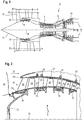
- the figure 1 represents in simplified manner an axial turbomachine. It is in this case a double-flow turbojet engine.
- the turbojet engine 2 comprises a first compression level, called a low-pressure compressor 4, a second compression level, called a high-pressure compressor 6, a combustion chamber 8 and one or more levels of turbines 10.
- a first compression level called a low-pressure compressor 4
- a second compression level called a high-pressure compressor 6
- a combustion chamber 8 and one or more levels of turbines 10.
- the compressors comprise several rows of rotor blades associated with rows of stator vanes. The rotation of the rotor about its axis of rotation 14 thus makes it possible to generate an air flow and to compress it progressively until it reaches the combustion chamber 8.
- An inlet fan commonly referred to as fan or blower 16 is coupled to the rotor 12 and generates an air flow which splits into a primary flow 18 passing through the various aforementioned levels of the turbomachine, and a secondary flow 20 passing through an annular duct (partially shown) along the machine to then join the primary flow at the turbine outlet.
- the secondary stream can be accelerated to generate a reaction.
- the primary 18 and secondary 20 streams are annular flows, they are channeled by the casing of the turbomachine.
- the casing has cylindrical walls or ferrules which can be internal and external.
- the figure 2 is a sectional view of a compressor of an axial turbomachine 2 such as that of the figure 1 .
- the compressor can be a low-pressure compressor 4.
- the rotor 12 comprises several rows of rotor blades 24, in this case three.
- the low pressure compressor 4 comprises several rectifiers, in this case four, each containing a row of stator vanes 26.
- the rectifiers are associated with the fan 16 or a row of rotor vanes to straighten the flow of air, so as to convert the speed of the flow into pressure.
- the stator vanes 26 extend substantially radially from an outer casing 28, and can be fixed thereto by means of an attachment pin 30.
- the inner ends of the stator vanes 26 can support an inner ferrule 32.
- Each inner ferrule 32 has a circular shape, and can be segmented. At least one or each inner ferrule 32 may be formed of angular segments. At least one or each inner ferrule 32 may make it possible to connect a plurality of stator vanes 26 of the same row.
- Each inner ferrule 32 can guide and / or delimit the primary flow 18.
- At least one or each inner ferrule 32 may comprise a sealing layer, such as an abradable layer 34 or friable layer, which is able to wear by friction with the rotor.
- a sealing layer such as an abradable layer 34 or friable layer, which is able to wear by friction with the rotor.
- Each abradable layer 34 may be adapted to cooperate with wipers, or annular ribs formed on the outer surface of the rotor 12 to provide a seal.
- Each abradable layer 34 may be silicone-based. The combination of wipers and an abradable layer makes it possible to limit the recirculations which reinject upstream of the inner shell 32 along the rotor 12.
- the figure 3 represents the diagram of the process for molding a resin layer inside a turbomachine shell.
- the process may be a method of molding abradable material in an axial turbomachine inner shell.
- the resin can become a layer of abradable material after polymerization.
- the polymerization can be prolonged after the demolding step 108.
- the figure 4 represents a portion or segment of mold 36 for the injection of a layer of abradable material, such as an elastomeric resin layer or silicone.
- the mold 36 may be circular and form a closed or open loop.
- the mold 36 can be placed one inside the ferrule. It can be applied gradually inside the ferrule by following the turn of the ferrule. Or again, the mold 36 can be segmented. It may be formed of several angular mold segments 36 which are arranged end to end to form a loop in the ferrule.
- the edges of the mold segments can be beveled.
- the mold 36 may be formed of at least two segments, for example eight segments.
- the edges of some segments may be parallel, other segments may have inclined edges of at least 60 °, for example forming right angles. Edge segments at right angles may be mounted, and those at parallel edges may be interspersed to form an alternation. This configuration makes it possible to form a self-stable assembly by virtue of the injection pressure. Segments with sloping edges can form keystones.
- a mold segment 36 includes an injection port or vent (not shown).
- the mold segments 36 may be made of polymer, possibly by additional manufacture, or by extrusion. This material can increase flexibility and preserve a reduced weight.
- the heat capacity is low, and may have a coefficient of expansion close to that of a composite shell.
- the mold 36 may have a profile of revolution in the general shape of the letter "U".
- the mold 36 has a circular wall 38 or annular axially extending, preferably predominantly axially.
- the mold may comprise annular walls 40 which extend generally radially, for example generally perpendicular to the axial wall 38.
- the mold 36 may comprise a radial wall 40 at each axial end of the axial wall 38. At least one or each radial wall 40 may comprise an annular hook 42.
- the mold 36 may comprise at least one annular reinforcing flange 44, for example an axial flange disposed on a radial wall 40. This flange can also facilitate the introduction of the mold 36, by providing more surface to bend the mold. 36 when it is put in place or demoulded. At least one flange 44 may be radially at the level of the associated hook 42.
- the mold 42 may have a profile of revolution about the axis of rotation of the turbomachine.
- the revolution profile is in a plane comprising the axis of rotation of the turbomachine.
- the figure 5 represents the profile of the injection mold 36.
- the axial wall 38 may have a general shape of tube, possibly conical or ogive. It can have forms of annular steps.
- the axial wall 38 may have radius variations in the axial direction. This feature allows for a layer of abradable finite dimension.
- At least one or each annular hook 42 may form an axially open annular groove.
- the annular hooks 42 may be facing each other, for example axially. They can be offset radially.
- At least one or each hook 42 may comprise a radial abutment surface 46 and / or a radial retention surface 48. These surfaces may be circular or annular, and may be coaxial.
- the mold 36 comprises an annular molding surface 50 which extends from one hook 36 to the other, and / or which is circumferentially delimited by at least one or each hook 36; possibly using a stop surface 46.
- At least one or each radially outer radial wall end 40 may have an annular guide surface 52, possibly conical.
- the guide surfaces 52 can move away from each other. They can extend mainly radially. They can give an annular tip shape to each radial wall 40.
- the axially measured length of the axial wall 38 is greater than the radially measured height of at least one, or each radial wall 40.
- the molding surface, that is to say the surface exposed to the resin, of the axial wall 38 is greater than the molding surface of each radial wall 40; which makes it possible to concentrate the effects of the pressure of the resin on the mold 36.
- the axial wall 38 may be finer than at least one or each radial wall 40, so as to promote the deformation of the wall axial 38 under the action of the pressure of the injected resin.
- the figure 6 represents a first intermediate phase of the step of (b) placing the mold 36 against the inner ferrule 32.
- the casing 28 may be a compressor casing such as that represented in FIG. figure 2 .
- the housing 28 may be made of composite, for example with an organic resin and a fiber preform.
- the stator vanes 26 are fixed on the housing 28, and arranged in annular rows.
- the blades 26 may comprise platforms 54 pressed against the inner surface of the casing 28.
- the platforms 54 may comprise fastening means 30, such as threaded rods inserted into the openings of the casing.
- the housing 28 is arranged vertically, flat against one of its axial faces; for example against the downstream face.
- the inner ends of the vanes 26 serve as a mounting support for the inner ferrules 32. These have openings in which are introduced the blade tips. Then, the ends of the blades 26 are fixed to the ferrule 32.
- the attachment can be with the aid of a retention plate.
- the clearance between the openings and the blade tips can be closed with a silicone seal, or even with the abradable material. Molding masks can then be applied to the openings, opposite the injection mold 36.
- the mold 36 is brought against the inner shell according to the arrow 56. It is brought radially from the inside. The outer ends of its radial walls 40 come into contact with the ferrule 32, for example upstream and downstream, on the upstream and downstream circular edges of the or each ferrule 32. Concerning the mold 36, the contact may be at the guide surfaces 52. The ferrule 32 may be bevelled opposite the guide surfaces. Pressing the mold 36 against the ferrule 32 can allow to spread, to open the mold 36.
- the figure 7 represents a second intermediate phase of step (b) placing the mold 36 against the shell 32. During this step, the mold revolution profile is bent, possibly arched so as to open.
- the profile of revolution of the wall 38 folds along the arrow 57.
- the guide surfaces 52 slide against the shell 32. They can be inclined relative to each other by an angle less than 90 °, preferably lower at 60 °, more preferably below 45 °; possibly less than 30 ° to reduce the radial force required for the axial opening of the mold 36.
- the axial wall 38 forms a circular virtual pivot for the hooks 42 by bending.
- the mold 36 opens so that the ferrule 32 enters the hooks 42.
- the thrust movement is prolonged until the ferrule 32 is fully engaged in the hooks 42, for example until the shell 32 comes against the abutment surfaces 46 of the hooks 42.
- the ferrule 32 may comprise corresponding receiving surfaces 47, able to receive the abutment surfaces 46 of the mold 36. These surfaces (46; 47) form the molding interface mold ferrule .
- At least one or each receiving surface 47 may be annular or arc portion, and may be oriented radially inwards.
- the retention surfaces overlap and / or partially marry the outer surface of the ferrule.
- the hooks 42 allow radial positioning, retention, blocking against the ferrule 32; in addition to indexing.
- the ferrule 32 can be inserted into the two hooks 42 at a time. Preferably, it is introduced into a hook 42 after the other, for example in the smaller diameter hook, then in the other.
- the figure 8 represents the mold 36 in position against the ferrule 32.
- the ferrule 32 and the mold 38 define a mold cavity 58.
- This cavity is an annular cavity 58 thanks to the mold when it is in one piece, or thanks to all its segments; the ferrule can also be segmented.
- the cavity 58 runs all the way around the shell. The inner ends of the blades may be present in the molding cavity.
- At least one or each hook 42 marries the upstream edge or the downstream edge of the shell 32. In this way, a seal may be created to prevent the resin from escaping despite the injection pressure which may be greater at 3 bars or even 10 bars.
- the surfaces of the hooks 42 may be sealing surfaces. This seal may be quite sufficient for the injection of a silicone resin, and a mold with at least two injection orifices and / or at least two vents; generally diametrically opposed.
- the ferrule 32 may have radial flanges upstream and downstream, the hooks can also marry these flanges to improve the seal.
- the figure 9 represents the step (c) of resin injection 60 inside the molding cavity.
- step (c) injection of the resin 60 into the molding cavity the pressure increases and remains high, at least the time that the resin is distributed.
- This pressure exerts a constraint against the axial wall 38 and deforms it so that its profile of revolution bends, arched according to the arrow 62, for example in the opposite direction that during step (b) installation of the mold 36.
- the hooks 42 are integral with the axial wall 38, they follow this deformation and increase their stress of Plating against the ferrule 32.
- the hooks 42 tend to approach one another, the revolution profiles of the axial walls swing towards one another.
- These deformations and stresses improve the seal between the hooks 42 and the shell 32, which has the effect of completing the effect of any circular seals (not shown).
- the circular seals can be removed.
- the pressure in the molding cavity may decrease as the resin polymerizes, and eventually become zero again.
- the hooks 42 of the mold 36 can substantially open.
- their abutment surfaces 46 tend to deviate radially inwardly of the receiving surfaces 47 of the shell 32.
- the molding interface opens, and resin can penetrate therethrough.
- the mold 42 can be removed from the ferrule. It can be extracted by deforming it, by removing the hooks and then pulling it radially inwards. Optionally, the mold can be destroyed for demolding. Due to the possible deformation of the hooks 42, a film of polymerized resin may cover at least partially at least one or each receiving surface of the ferrule.
Description
L'invention a trait à l'injection d'une couche de matériau abradable sous une virole interne de turbomachine axiale. Plus précisément, l'invention a trait à un segment angulaire de moule pour injection d'une couche de matériau abradable à l'intérieur d'une virole interne de compresseur de turbomachine axiale. L'invention a également trait à une méthode de fabrication d'une turbomachine munie d'une virole avec une couche de silicone injectée. L'invention traite également d'un procédé de moulage d'une couche de matériau abradable à l'intérieur d'une virole interne de turbomachine axiale.The invention relates to the injection of a layer of abradable material under an axial turbine engine inner shroud. More specifically, the invention relates to a mold angular segment for injection of a layer of abradable material inside an axial ferrule compressor inner shell. The invention also relates to a method of manufacturing a turbomachine provided with a ferrule with an injected silicone layer. The invention also relates to a method of molding a layer of abradable material inside an axial turbomachine inner shell.
Dans l'optique d'augmenter leurs taux de compression, les étages de compression d'un compresseur d'une turbomachine axiale sont munis de joints d'étanchéités. Ces joints sont appliqués sur les surfaces intérieures des viroles externes et des viroles internes. Ces joints sont en matériaux abradables ou friables, qui sont aptes à s'éroder en cas de contact avec le rotor. Ces joints peuvent entrer en contact d'extrémités d'aubes rotoriques ou de léchettes sans les dégrader. De la sorte, il est possible de réduire les jeux dynamiques au niveau des joints tout en préservant l'intégrité mécanique des éléments aérodynamiques.In order to increase their compression ratios, the compression stages of a compressor of an axial turbomachine are provided with seals. These seals are applied to the inner surfaces of the outer ferrules and inner ferrules. These seals are abradable or friable materials, which are able to erode in case of contact with the rotor. These seals can come into contact with the ends of rotor blades or wipers without degrading them. In this way, it is possible to reduce the dynamic clearances at the joints while preserving the mechanical integrity of the aerodynamic elements.
Les joints peuvent être en un matériau silicone qui est injecté directement sur la virole à l'aide d'un moule. Un tel moule peut être fixé à même le stator, et définit une cavité de moulage en combinaison avec la virole interne. La cavité ainsi formée correspond généralement à la forme définitive de la piste d'abradable, si besoin la piste d'abradable peut être usinée suite au démoulage.The seals may be of a silicone material which is injected directly onto the shell using a mold. Such a mold can be fixed to the stator, and defines a molding cavity in combination with the inner ferrule. The cavity thus formed generally corresponds to the final shape of the abradable track, if necessary the abradable track can be machined following demoulding.
Le document
Le document
Le document
Le document
L'invention a pour objectif de résoudre au moins un des problèmes posés par l'art antérieur. Plus précisément, l'invention a pour objectif de simplifier un moule d'injection d'une couche d'abradable à l'intérieur d'une virole de turbomachine axiale. L'invention a également pour objectif de simplifier le procédé de moulage d'une couche de résine à l'intérieur d'une virole interne de turbomachine axiale.The object of the invention is to solve at least one of the problems posed by the prior art. More specifically, the invention aims to simplify an injection mold of an abradable layer inside an axial turbomachine shell. Another object of the invention is to simplify the process for molding a resin layer inside an axial turbomachine inner shell.
L'invention a pour objet un moule pour injection d'une couche de matériau abradable à l'intérieur d'une virole de turbomachine axiale, le moule comprenant une paroi circulaire s'étendant axialement, deux parois annulaires s'étendant radialement vers l'extérieur depuis les extrémités axiales de la paroi axiale ; les parois étant configurées pour former une cavité annulaire de moulage à l'intérieur de la virole en combinaison avec la virole, remarquable en ce que chaque paroi radiale du moule comprend un crochet annulaire destiné à être en contact de la surface externe de la virole de sorte à permettre un maintien du moule par rapport à la virole.The invention relates to a mold for injecting a layer of abradable material inside an axial turbomachine shell, the mold comprising a circular wall extending axially, two annular walls extending radially towards the outside from the axial ends of the axial wall; the walls being configured to form an annular mold cavity inside the ferrule in combination with the ferrule, characterized in that each radial wall of the mold comprises an annular hook intended to be in contact with the outer surface of the ferrule of the ferrule. so as to allow maintenance of the mold relative to the ferrule.
Selon un mode avantageux de l'invention, les crochets forment des gorges annulaires ouvertes axialement l'une vers l'autre, chaque crochet comprend une surface annulaire de rétention configurée pour permettre une rétention radiale entre le crochet et la virole, et une surface annulaire de butée configurée pour venir en butée radialement contre la virole, lesdites surfaces annulaires étant coaxiales.According to an advantageous embodiment of the invention, the hooks form annular grooves open axially towards each other, each hook comprises an annular retention surface configured to allow radial retention between the hook and the ferrule, and an annular surface. stopper configured to abut radially against the ferrule, said annular surfaces being coaxial.
Selon un mode avantageux de l'invention, le moule est segmenté, éventuellement le moule est réalisé en un matériau polymère.According to an advantageous embodiment of the invention, the mold is segmented, optionally the mold is made of a polymeric material.
Selon un mode avantageux de l'invention, le moule est formé de deux à seize segments angulaires, préférentiellement de quatre à douze segments angulaires, au moins un des segments comprend des extrémités, selon circonférence, planes et parallèles, et au moins un des segments comprend des extrémités planes dont les plans sont inclinés d'au moins 60°, préférentiellement au moins 90°.According to an advantageous embodiment of the invention, the mold is formed of two to sixteen angular segments, preferably four to twelve angular segments, at least one of the segments comprises ends, circumferentially, planar and parallel, and at least one of segments comprises planar ends whose planes are inclined at least 60 °, preferably at least 90 °.
Selon un mode avantageux de l'invention, les extrémités radialement externes des parois radiales comprennent des surfaces extérieures de guidage, éventuellement coniques, qui s'écartent l'une de l'autre vers l'extérieur de sorte à faciliter l'écartement des crochets lors de l'insertion de la virole dans le moule.According to an advantageous embodiment of the invention, the radially outer ends of the radial walls comprise outer guide surfaces, possibly conical, which move away from each other to the outside so as to facilitate the spacing of the hooks. when inserting the ferrule into the mold.
Selon un mode avantageux de l'invention, la paroi axiale comprend une portion annulaire de moindre épaisseur disposée axialement en son centre, préférentiellement l'épaisseur de la paroi axiale est inférieure à l'épaisseur des parois radiales.According to an advantageous embodiment of the invention, the axial wall comprises an annular portion of smaller thickness disposed axially at its center, preferably the thickness of the axial wall is less than the thickness of the radial walls.
Selon un mode avantageux de l'invention, la longueur axiale de la paroi axiale est supérieure à la hauteur radiale de chaque paroi radiale, préférentiellement le profil de révolution de la paroi axiale est sensiblement incurvé vers l'intérieur de sorte que lors de l'injection de la résine, la résine tend à arquer vers l'intérieur le profil de révolution de la paroi axiale de sorte à plaquer d'avantage les parois radiales contre la virole.According to an advantageous embodiment of the invention, the axial length of the axial wall is greater than the radial height of each radial wall, preferably the profile of revolution of the axial wall is substantially curved inwards so that during the Injection of the resin, the resin tends to arc inward the profile of revolution of the axial wall so as to further press the radial walls against the ferrule.
Selon un mode avantageux de l'invention, la virole est une virole interne.According to an advantageous embodiment of the invention, the ferrule is an internal ferrule.
L'invention a également pour objet un procédé de moulage d'une couche de résine, notamment de matériau abradable, à l'intérieur d'une virole de turbomachine axiale, le procédé comprenant les étapes de : (a) fourniture ou fabrication d'une virole de turbomachine, ladite virole étant reliée à une rangée annulaire d'aubes statoriques, (b) mise en place d'un moule contre la virole de sorte à définir une cavité annulaire de moulage à l'intérieur de la virole, (c) injection d'une résine à l'intérieur de la cavité de moulage, remarquable en ce que le moule comprend des crochets annulaires configurés pour maintenir le moule contre la virole, et en ce que lors de l'étape (b) mise en place du moule contre la virole, le moule est déformé de sorte à engager la virole dans les crochets du moule.The subject of the invention is also a process for molding a resin layer, in particular an abradable material, inside an axial turbomachine shell, the method comprising the steps of: (a) supply or manufacture of a turbomachine shell, said ferrule being connected to an annular row of stator vanes, (b) placing a mold against the ferrule so as to define an annular mold cavity inside the ferrule, (c ) injecting a resin inside the molding cavity, characterized in that the mold comprises annular hooks configured to hold the mold against the ferrule, and in that step (b) in place of the mold against the ferrule, the mold is deformed so as to engage the ferrule in the hooks of the mold.
Selon un mode avantageux de l'invention, le moule comprend au moins deux crochets disposés en amont et en aval de la virole, et en ce que lors de l'étape (b) mise en place du moule, la virole est engagée dans les crochets en les écartant axialement l'un de l'autre.According to an advantageous embodiment of the invention, the mold comprises at least two hooks arranged upstream and downstream of the shell, and in that step (b) of placing the mold, the ferrule is engaged in the hooks by spacing them axially from each other.
Selon un mode avantageux de l'invention, chaque crochet assure une étanchéité entre le moule et la virole, préférentiellement une étanchéité circulaire.According to an advantageous embodiment of the invention, each hook ensures a seal between the mold and the ferrule, preferably a circular seal.
Selon un mode avantageux de l'invention, lors de l'étape (b) mise en place du moule contre la virole, le moule est pressé radialement contre la virole.According to an advantageous embodiment of the invention, during step (b) placing the mold against the ferrule, the mold is pressed radially against the ferrule.
Selon un mode avantageux de l'invention, les crochets comprennent chacun une surface de butée radiale et une surface de rétention radiale du moule à la virole, lesdites surfaces étant radialement opposées et éventuellement annulaires, et en ce que lors de l'étape (b) mise en place du moule contre la virole, la surface de butée radiale épouse la virole sur toute sa longueur.According to an advantageous embodiment of the invention, the hooks each comprise a radial abutment surface and a radial retention surface of the mold to the ferrule, said surfaces being radially opposite and possibly annular, and in that during step (b ) placing the mold against the ferrule, the radial abutment surface embraces the ferrule over its entire length.
Selon un mode avantageux de l'invention, le moule comprend une paroi annulaire s'étendant axialement entre les crochets, et en ce que lors de l'étape (b) mise en place du moule contre la virole, la paroi axiale est pliée, préférentiellement la paroi axiale comprend un profil de révolution qui est arqué lors de la mise en place du moule contre la virole.According to an advantageous embodiment of the invention, the mold comprises an annular wall extending axially between the hooks, and in that during step (b) placing the mold against the ferrule, the axial wall is folded, preferably the axial wall comprises a profile of revolution which is arched during the establishment of the mold against the ferrule.
Selon un mode avantageux de l'invention, lors de l'étape (c) injection, la résine exerce une pression contre la paroi axiale et l'arque de sorte à rapprocher les crochets annulaires en les plaquant contre la virole, préférentiellement la résine comprend du silicone.According to an advantageous embodiment of the invention, during step (c) injection, the resin exerts a pressure against the axial wall and the arch so as to bring the annular hooks together by pressing them against the ferrule, preferably the resin comprises silicone.
Selon un mode avantageux de l'invention, la virole est une virole interne.According to an advantageous embodiment of the invention, the ferrule is an internal ferrule.
L'invention a également pour objet une méthode de fabrication d'une turbomachine comprenant une virole avec une couche annulaire de matériau abradable moulée à l'intérieur de la virole, la couche d'abradable étant moulée selon un procédé de moulage, remarquable en ce que le procédé de moulage est conforme à l'invention, et la virole comprend au moins une surface de réception de crochet annulaire de moule destiné à être accroché à la virole, la au moins une surface de réception étant au moins partiellement recouverte d'un film de matériau abradable.The invention also relates to a method of manufacturing a turbomachine comprising a ferrule with an annular layer of abradable material molded inside the shell, the abradable layer being molded according to a molding process, remarkable in that that the molding method is in accordance with the invention, and the ferrule comprises at least one mold annular hook receiving surface intended to be attached to the shell, the at least one receiving surface being at least partially covered with a film of abradable material.
Selon un mode avantageux de l'invention, au moins une ou chaque surface de réception est une surface annulaire ou en arc de cercle, et/ou elle est une surface orientée radialement vers l'intérieur.According to an advantageous embodiment of the invention, at least one or each receiving surface is an annular or arcuate surface, and / or it is a surface oriented radially inwards.
Selon un mode avantageux de l'invention, au moins une ou chaque surface de réception délimite axialement la couche annulaire de matériau abradable, et est éventuellement destinée à épouser une surface de butée du crochet annulaire du moule.According to an advantageous embodiment of the invention, at least one or each receiving surface axially delimits the annular layer of abradable material, and is optionally designed to fit an abutment surface of the annular hook of the mold.
Selon un mode avantageux de l'invention, au moins un ou chaque crochet est délimité par une surface de guidage.According to an advantageous embodiment of the invention, at least one or each hook is delimited by a guide surface.
Selon un mode avantageux de l'invention, les crochets sont à distance radialement de la paroi axiale, éventuellement d'une distance supérieure à l'épaisseur de la paroi axiale.According to an advantageous embodiment of the invention, the hooks are spaced radially from the axial wall, possibly a distance greater than the thickness of the axial wall.
Selon un mode avantageux de l'invention, la hauteur radiale d'au moins un ou de chaque crochet est supérieure ou égale à la hauteur radiale de la surface de guidage associée.According to an advantageous embodiment of the invention, the radial height of at least one or each hook is greater than or equal to the radial height of the associated guide surface.
Selon un mode avantageux de l'invention, au moins une ou chaque surface de rétention présente un profil de révolution courbe, qui forme éventuellement un quart de cercle.According to an advantageous embodiment of the invention, at least one or each retention surface has a curved profile of revolution, which possibly forms a quarter circle.
Selon un mode avantageux de l'invention, au moins une ou chaque surface de butée est sensiblement tubulaire et éventuellement parallèle à l'axe de la turbomachine.According to an advantageous embodiment of the invention, at least one or each abutment surface is substantially tubular and possibly parallel to the axis of the turbomachine.
Selon un mode avantageux de l'invention, les surfaces de butée sont parallèles.According to an advantageous embodiment of the invention, the abutment surfaces are parallel.
Selon un mode avantageux de l'invention, les parois radiales se chevauchent radialement.According to an advantageous embodiment of the invention, the radial walls overlap radially.
Selon un mode avantageux de l'invention, les parois radiales sont en regard l'une de l'autre, et éventuellement généralement parallèles.According to an advantageous embodiment of the invention, the radial walls are facing one another, and possibly generally parallel.
Selon un mode avantageux de l'invention, les crochets sont configurés pour se bloquer radialement sur une extrémité axiale de la virole, préférentiellement pincer axialement la virole.According to an advantageous embodiment of the invention, the hooks are configured to lock radially on an axial end of the ferrule, preferably axially pinch the ferrule.
Selon un mode avantageux de l'invention, au moins un ou chaque crochet a une forme de gorge annulaire, éventuellement ouverte axialement.According to an advantageous embodiment of the invention, at least one or each hook has an annular groove shape, possibly open axially.
Selon un mode avantageux de l'invention, la hauteur radiale d'au moins un ou de chaque gorge annulaire est supérieure à la profondeur axiale de ladite gorge.According to an advantageous embodiment of the invention, the radial height of at least one or each annular groove is greater than the axial depth of said groove.
Selon un mode avantageux de l'invention, le moule est configuré pour se déformer de manière élastique lors de l'insertion de la virole à l'intérieur des crochets.According to an advantageous embodiment of the invention, the mold is configured to deform elastically during the insertion of the ferrule into the hooks.
Selon un mode avantageux de l'invention, les crochets annulaires permettent un blocage radial du moule par rapport à la virole, et/ou les crochets sont disposés à des extrémités axiales opposées du moule.According to an advantageous embodiment of the invention, the annular hooks allow a radial locking of the mold relative to the ferrule, and / or the hooks are disposed at opposite axial ends of the mold.
Selon un mode avantageux de l'invention, la portion tubulaire est destinée à être disposée à l'intérieur de la virole, et/ou chaque paroi annulaire est destinée à être en contact d'une extrémité axiale de la virole.According to an advantageous embodiment of the invention, the tubular portion is intended to be disposed inside the ferrule, and / or each annular wall is intended to be in contact with an axial end of the ferrule.
Selon un mode avantageux de l'invention, le moule forme un ressort, et/ou le moule forme une pince.According to an advantageous embodiment of the invention, the mold forms a spring, and / or the mold forms a clamp.
L'invention permet d'exploiter la rigidité de la virole pour réduire celle du moule, ce dernier pouvant alors être aminci ; allégé. Il peut également devenir sensiblement souple. La virole devient alors un support de positionnement et un repère pour la circularité de la couche d'abradable. L'invention permet également d'améliorer l'homogénéité de l'épaisseur d'une couche de résine moulée à l'intérieur d'une virole interne de turbomachine axiale.The invention makes it possible to exploit the rigidity of the shell to reduce that of the mold, the latter then being able to be thinned; lightened. It can also become substantially flexible. The shell then becomes a positioning support and a reference for the circularity of the abradable layer. The invention also makes it possible to improve the homogeneity of the thickness of a resin layer molded inside an axial turbomachine inner shell.
Le caractère auto-stable des segments de moule permet de réduire les supports de maintien, ce qui permet de réduire la capacité thermique de l'outillage, tout comme la réalisation des segments de moule en polymère. Lors de la mise en étuve, la température monte plus rapidement et réduit le temps de fabrication.The self-stable nature of the mold segments makes it possible to reduce the holding supports, which makes it possible to reduce the heat capacity of the tooling, just like the production of the polymer mold segments. When placed in an oven, the temperature rises faster and reduces the manufacturing time.
L'emploi du polymère est particulièrement avantageux dans le cas de virole composites car on limite la dilatation différentielle. Le poids de chaque segment est de l'ordre de 100 grammes. Leur mise en place manuelle est aussi simple que la place nécessaire à leur stockage est réduite.The use of the polymer is particularly advantageous in the case of composite shell because it limits the differential expansion. The weight of each segment is of the order of 100 grams. Their manual placement is as simple as the space required for their storage is reduced.
L'invention permet de réduite les coûts du moule car elle permet de s'adapter à des diamètres, à des longueurs axiales différents mais proches. Ainsi, une turbomachine présentant différentes viroles internes avec des évolutions géométriques sensibles pourra recevoir des pistes d'abradable à l'aide d'un même modèle de moule grâce à sa souplesse.The invention makes it possible to reduce mold costs because it makes it possible to adapt to diameters at different but close axial lengths. Thus, a turbomachine having different internal ferrules with sensitive geometric evolutions can receive abradable tracks using a same mold model thanks to its flexibility.
Le faible coût des segments permet un emploi unique, en conséquence de quoi l'érosion du moule devient négligeable malgré la présence de la charge dans la résine. L'étape de nettoyage du moule est également éliminée, ce qui réduit encore les coûts.The low cost of the segments allows a single use, as a result of which the erosion of the mold becomes negligible despite the presence of the charge in the resin. The mold cleaning step is also eliminated, further reducing costs.
-
La
figure 1 représente une turbomachine axiale selon l'invention.Thefigure 1 represents an axial turbomachine according to the invention. -
La
figure 2 est un schéma d'un compresseur de turbomachine selon l'invention.Thefigure 2 is a diagram of a turbomachine compressor according to the invention. -
La
figure 3 représente un diagramme du procédé de réalisation de moulage selon l'invention.Thefigure 3 represents a diagram of the molding production method according to the invention. -
La
figure 4 illustre un moule d'injection de résine selon l'invention.Thefigure 4 illustrates a resin injection mold according to the invention. -
La
figure 5 ébauche le profil du moule selon l'invention.Thefigure 5 roughing the profile of the mold according to the invention. -
La
figure 6 illustre une première étape intermédiaire de mise en place du moule contre la virole selon l'invention.Thefigure 6 illustrates a first intermediate step of placing the mold against the ferrule according to the invention. -
La
figure 7 illustre une deuxième étape intermédiaire de mise en place du moule contre la virole selon l'invention.Thefigure 7 illustrates a second intermediate step of placing the mold against the ferrule according to the invention. -
La
figure 8 illustre le résultat de la mise en place du moule contre la virole selon l'invention.Thefigure 8 illustrates the result of the establishment of the mold against the ferrule according to the invention. -
La
figure 9 illustre l'étape d'injection d'une résine dans la cavité de moulage selon l'invention.Thefigure 9 illustrates the step of injecting a resin into the molding cavity according to the invention.
Dans la description qui va suivre, les termes intérieur ou interne et extérieur ou externe renvoient à un positionnement par rapport à l'axe de rotation d'une turbomachine axiale.In the following description, the terms inner or inner and outer or outer refer to a positioning relative to the axis of rotation of an axial turbomachine.
La
Un ventilateur d'entrée communément désigné fan ou soufflante 16 est couplé au rotor 12 et génère un flux d'air qui se divise en un flux primaire 18 traversant les différents niveaux sus mentionnés de la turbomachine, et un flux secondaire 20 traversant un conduit annulaire (partiellement représenté) le long de la machine pour ensuite rejoindre le flux primaire en sortie de turbine. Le flux secondaire peut être accéléré de sorte à générer une réaction. Les flux primaire 18 et secondaire 20 sont des flux annulaires, ils sont canalisés par le carter de la turbomachine. A cet effet, le carter présente des parois cylindriques ou viroles qui peuvent être internes et externes.An inlet fan commonly referred to as fan or
La
Le compresseur basse pression 4 comprend plusieurs redresseurs, en l'occurrence quatre, qui contiennent chacun une rangée d'aubes statoriques 26. Les redresseurs sont associés au fan 16 ou à une rangée d'aubes rotoriques pour redresser le flux d'air, de sorte à convertir la vitesse du flux en pression.The
Les aubes statoriques 26 s'étendent essentiellement radialement depuis un carter extérieur 28, et peuvent y être fixées à l'aide d'un axe de fixation 30. Les extrémités internes des aubes statoriques 26 peuvent supporter une virole interne 32. Chaque virole interne 32 présente une forme circulaire, et peut être segmentée. Au moins une ou chaque virole interne 32 peut être formée de segments angulaires. Au moins une ou chaque virole interne 32 peut permettre de relier plusieurs aubes statoriques 26 d'une même rangée. Chaque virole interne 32 peut permettre de guider et/ou de délimiter le flux primaire 18.The stator vanes 26 extend substantially radially from an
Au moins une ou chaque virole interne 32 peut comprendre une couche d'étanchéité, telle une couche abradable 34 ou couche friable, qui est apte à s'user par frottement avec le rotor. Chaque couche d'abradable 34 peut être destinée à coopérer avec des léchettes, ou nervures annulaires formées sur la surface extérieure du rotor 12 afin d'assurer une étanchéité. Chaque couche d'abradable 34 peut être à base de silicone. La combinaison de léchettes et d'une couche d'abradable permet de limiter les recirculations qui se réinjectent en amont de la virole interne 32 en longeant le rotor 12.At least one or each
La
Le procédé peut comprendre l'enchainement des étapes suivantes ; éventuellement dans cet ordre :
- (a) fourniture
ou fabrication 100 d'une virole interne de turbomachine, ladite virole étant reliée à une rangée annulaire d'aubes statoriques, - (b) mise en
place 102 d'un moule contre la virole interne de sorte à définir une cavité annulaire de moulage à l'intérieur de la virole, - (c)
injection 104 d'une résine à l'intérieur de la cavité de moulage, - (d) polymérisation 106 de la résine ;
- (e) démoulage 108 de la virole et de la couche d'abradable.
- (a) supply or manufacture 100 of a turbomachine inner shroud, said ferrule being connected to an annular row of stator vanes,
- (b) placing a
mold 102 against the inner ferrule so as to define an annular mold cavity inside the ferrule, - (c) injecting a
resin 104 into the mold cavity, - (d) polymerizing the resin;
- (e) demolding 108 of the ferrule and the abradable layer.
Il est à noter que la polymérisation peut se prolonger après l'étape démoulage 108.It should be noted that the polymerization can be prolonged after the
La
Le moule 36 peut être circulaire et former une boucle fermée ou bien ouverte. Le moule 36 peut être placé d'un tenant à l'intérieur de la virole. Il peut être appliqué progressivement à l'intérieur de la virole en suivant le tour de la virole. Ou encore, le moule 36 peut être segmenté. Il peut être formé de plusieurs segments angulaires de moule 36 qui sont disposés bout à bout pour former une boucle dans la virole.The
Les bords des segments de moule peuvent être biseautés. Le moule 36 peut être formé d'au moins deux segments, par exemple huit segments. Les bords de certains segments peuvent être parallèles, d'autres segments peuvent avoir des bords inclinés d'au moins 60°, par exemple en formant des angles droits. Les segments à bords à angles droits peuvent être montés, puis ceux à bords à parallèles peuvent être intercalés pour former une alternance. Cette configuration permet de former un ensemble auto-stable grâce à la pression d'injection. Les segments à bords inclinés peuvent former des clés de voute. Eventuellement un segment de moule 36 comprend un orifice d'injection ou un évent (non représenté).The edges of the mold segments can be beveled. The
Les segments de moule 36 peuvent être réalisés en polymère, éventuellement par fabrication additionnelle, ou par extrusion. Ce matériau peut augmenter la souplesse et préserver un poids réduit. La capacité thermique est faible, et peut présenter un coefficient de dilatation proche de celui d'une virole composite.The
Le moule 36 peut présenter un profil de révolution en forme générale de la lettre « U ». Le moule 36 présente une paroi circulaire 38 ou annulaire qui s'étend axialement, préférentiellement majoritairement axialement. Le moule peut comprendre des parois annulaires 40 qui s'étendent généralement radialement, par exemple généralement perpendiculairement à la paroi axiale 38. Le moule 36 peut comprendre une paroi radiale 40 à chaque extrémité axiale de la paroi axiale 38. Au moins une, ou chaque paroi radiale 40 peut comprendre un crochet annulaire 42.The
Le moule 36 peut comprendre au moins une bride annulaire de renfort 44, par exemple une bride axiale disposée sur une paroi radiale 40. Cette bride peut également faciliter la mise en place du moule 36, en offrant d'avantage de surface pour plier le moule 36 lors de sa mise en place ou du démoulage. Au moins une bride 44 peut être au niveau radialement du crochet associé 42.The
Le moule 42 peut présenter un profil de révolution autour de l'axe de rotation de la turbomachine. Le profil de révolution est selon un plan comprenant l'axe de rotation de la turbomachine.The
La
La paroi axiale 38 peut présenter une forme générale de tube, éventuellement conique ou en ogive. Elle peut présenter des formes de marches annulaires. La paroi axiale 38 peut présenter des variations de rayon selon la direction axiale. Cette particularité permet de réaliser une couche d'abradable à cote finie.The
Au moins un ou chaque crochet annulaire 42 peut former une gorge annulaire ouverte axialement. Les crochets annulaires 42 peuvent être en regard l'un de l'autre, par exemple axialement. Ils peuvent être décalés radialement. Au moins un ou chaque crochet 42 peut comprendre une surface de butée radiale 46 et/ou une surface de rétention radiale 48. Ces surfaces peuvent être circulaire ou annulaires, et être coaxiales. Le moule 36 comprend une surface de moulage annulaire 50 qui s'étend d'un crochet 36 à l'autre, et/ou qui est délimitée selon la circonférence par au moins un ou chaque crochet 36 ; éventuellement à l'aide d'une surface de butée 46.At least one or each
Au moins une ou chaque extrémité radiale externe de paroi radiale 40 peut présenter une surface de guidage annulaire 52, éventuellement conique. Les surfaces de guidage 52 peuvent s'écarter l'une de l'autre vers l'extérieur. Elles peuvent s'étendre majoritairement radialement. Elles peuvent donner une forme de pointe annulaire à chaque paroi radiale 40.At least one or each radially outer
La longueur mesurée axialement de la paroi axiale 38 est supérieure à la hauteur mesurée radialement d'au moins une, ou de chaque paroi radiale 40. La surface de moulage, c'est-à-dire la surface exposée à la résine, de la paroi axiale 38 est supérieure à la surface de moulage de chaque paroi radiale 40 ; ce qui permet de concentrer les effets de la pression de la résine sur le moule 36. En complément, la paroi axiale 38 peut être plus fine qu'au moins une ou que chaque paroi radiale 40, de sorte à favoriser la déformation de la paroi axiale 38 sous l'action de la pression de la résine injectée.The axially measured length of the
La
Un carter externe 28 de compresseur avec des aubes 26 et une ou plusieurs viroles 32 est préalablement fourni ou fabriqué. Le carter 28 peut être un carter de compresseur tel que celui représenté en
Les extrémités internes des aubes 26 servent de support de fixation pour les viroles internes 32. Celles-ci présentent des ouvertures dans lesquelles sont introduites les extrémités d'aubes. Ensuite, les extrémités d'aubes 26 sont fixées à la virole 32. La fixation peut être à l'aide d'une plaquette de rétention. Le jeu entre les ouvertures et les extrémités d'aubes peut être refermé à l'aide d'un joint silicone, ou à l'aide même du matériau abradable. Des masques de moulage peuvent alors être appliqués sur les ouvertures, à l'opposé du moule 36 d'injection.The inner ends of the
Le moule 36 est amené contre la virole interne selon la flèche 56. Il est approché radialement depuis l'intérieur. Les extrémités externes de ses parois radiales 40 viennent en contact de la virole 32, par exemple en amont et en aval, sur les bords circulaires amont et aval de la ou de chaque virole 32. Concernant le moule 36, le contact peut être au niveau des surfaces de guidage 52. La virole 32 peut être biseautée en regard des surfaces de guidage. Presser le moule 36 contre la virole 32 peut permettre d'écarter, d'ouvrir le moule 36.The
La
En pressant radialement le moule vers la virole 32 selon la flèche 56, il tend à s'ouvrir axialement. Le profil de révolution de la paroi 38 se plie selon la flèche 57. Les surfaces de guidage 52 glissent contre la virole 32. Elles peuvent être inclinées l'une par rapport à l'autre d'un angle inférieur à 90°, préférentiellement inférieur à 60°, plus préférentiellement inférieur à 45° ; éventuellement inférieur à 30° pour diminuer l'effort radial nécessaire à l'ouverture axiale du moule 36. La paroi axiale 38 forme un pivot virtuel circulaire pour les crochets 42 en se pliant.By radially pressing the mold towards the
Le moule 36 s'ouvre pour que la virole 32 entre dans les crochets 42. Le mouvement de poussée est prolongé jusqu'à ce que la virole 32 soit totalement engagée dans les crochets 42, par exemple jusqu'à ce que la virole 32 vienne contre les surfaces de butée 46 des crochets 42. La virole peut 32 peut comprendre des surfaces de réception 47 correspondantes, aptes à recevoir les surfaces de butée 46 du moule 36. Ces surfaces (46 ; 47) forment l'interface de moulage moule virole. Au moins une ou chaque surface de réception 47 peut être annulaire ou une portion d'arc, et peut être orientée radialement vers l'intérieur. Les surfaces de rétention recouvrent et/ou épousent partiellement la surface externe de la virole. Ainsi, les crochets 42 permettent un positionnement radial, une rétention, un blocage contre la virole 32 ; en plus d'un indexage.The
La virole 32 peut être introduite dans les deux crochets 42 à la fois. Préférentiellement, elle est introduite dans un crochet 42 après l'autre, par exemple dans le crochet de plus petit diamètre, puis dans l'autre.The
La
Lorsque la position en butée est atteinte, la virole 32 et le moule 38 délimitent une cavité de moulage 58. Cette cavité est une cavité annulaire 58 grâce au moule lorsqu'il est d'un seul tenant, ou grâce à tous ses segments ; la virole pouvant également être segmentée. La cavité 58 parcourt tout le tour de la virole. Les extrémités internes des aubes peuvent être présentes dans la cavité de moulage.When the abutment position is reached, the
Au moins un ou chaque crochet 42 épouse le bord amont ou le bord aval de la virole 32. De la sorte, une étanchéité peut être créée afin d'éviter que la résine ne s'échappe malgré la pression d'injection qui peut être supérieure à 3 bars ou même 10 bars. Les surfaces des crochets 42 peuvent être des surfaces d'étanchéité. Cette étanchéité peut être tout à fait suffisante pour l'injection d'une résine silicone, et un moule avec au moins deux orifices d'injection et/ou au moins deux évents ; généralement diamétralement opposés. La virole 32 pouvant présenter des brides radiales en amont et en aval, les crochets peuvent également épouser ces brides pour améliorer l'étanchéité.At least one or each
La
Lors de l'étape (c) injection de la résine 60 dans la cavité de moulage, la pression augmente et reste élevée, au moins le temps que la résine se répartisse. Cette pression exerce une contrainte contre la paroi axiale 38 et la déforme de sorte que son profil de révolution se plie, s'arque selon la flèche 62, par exemple dans le sens inverse que lors de l'étape (b) mise en place du moule 36. Puisque les crochets 42 sont solidaires de la paroi axiale 38, ils suivent cette déformation et augmentent leur contrainte de plaquage contre la virole 32. Les crochets 42 tendent à se rapprocher l'un de l'autre, les profils de révolution des parois axiales basculent l'un vers l'autre. Ces déformations et contraintes améliorent l'étanchéité entre les crochets 42 et la virole 32, ce qui a pour effet de compléter l'effet d'éventuels joints circulaires (non représentés). Eventuellement, les joints circulaires peuvent être supprimés. La pression dans la cavité de moulage peut diminuer à mesure que la résine polymérise, et éventuellement redevenir nulle.During step (c) injection of the
Toujours en raison de la pression d'injection, les crochets 42 du moule 36 peuvent sensiblement s'ouvrir. Ainsi, leurs surfaces de butée 46 tendent à s'écarter radialement vers l'intérieur des surfaces de réception 47 de la virole 32. Dès lors l'interface de moulage s'ouvre, et de la résine peut y pénétrer.Still due to the injection pressure, the
Suite à la totale polymérisation de la résine, le moule 42 peut être démonté de la virole. Il peut être extrait en le déformant, en écartant les crochets puis en le tirant radialement vers l'intérieur. Eventuellement, le moule peut être détruit pour le démoulage. En raison de l'éventuelle déformation des crochets 42, une pellicule de résine polymérisée peut recouvrir au moins partiellement au moins une ou chaque surface de réception de la virole.Following the total polymerization of the resin, the
Dans la description, les caractéristiques sont présentées en relation avec une virole interne. Toutefois, l'invention s'applique en totalité à une virole externe, continue ou segmentée.In the description, the features are presented in connection with an inner ferrule. However, the invention applies in full to an outer shell, continuous or segmented.
Claims (15)
- A mould (36) for injecting a layer of abradable material (34) inside a shroud (32) of an axial-flow turbomachine (2), the mould (36) comprising a circular wall extending axially (38) and two annular walls extending radially (40) outwardly from the axial ends of the axial wall (38); the walls (38; 40) being configured to form an annular moulding cavity (58) inside the shroud (32) in combination with the shroud (32),
characterized in that
each radial wall (40) of the mould comprises an annular hook (42) intended to be in contact with the outer surface of the shroud (32) so as to allow the mould (36) to be held in relation to the shroud (32). - Mould (36) according to Claim 1, characterized in that the hooks (42) form annular grooves that are open axially towards one another, each hook (42) comprises an annular retention surface (48) configured to allow a radial retention between the hook and the shroud (32), and an annular stop surface (46) configured to come into radial abutment against the shroud (32), said annular surfaces being coaxial.
- Mould (36) according to one of Claims 1 or 2, characterized in that it is segmented, and the mould (36) is possibly made of a polymeric material.
- Mould (36) according to one of Claims 1 or 3, characterized in that it is formed from two to sixteen angular segments, preferably from four to twelve angular segments, at least one of the segments comprises planar and parallel ends, along the circumference, and at least one of the segments comprises planar ends of which the planes are inclined by at least 60°, preferably at least 90°.
- Mould (36) according to one of Claims 1 or 4, characterized in that the radially outer ends of the radial walls (40) have outer guiding surfaces (52), possibly conical, which spread apart from one another outwardly so as to facilitate the spreading of the hooks (42) as the shroud (32) is inserted into the mould (36).
- Mould (36) according to one of Claims 1 or 5, characterized in that the axial wall (38) comprises a thinner annular portion disposed axially at the centre thereof, the thickness of the axial wall (38) preferably being less than the thickness of the radial walls (40).
- Mould (36) according to one of Claims 1 or 6, characterized in that the axial length of the axial wall (38) is greater than the radial height of each radial wall (40), the revolution profile of the axial wall (38) preferably being substantially curved inwardly, such that, as the resin is injected, the resin tends to arch the revolution profile of the axial wall (38) inwardly so as to better press the radial walls (40) against the shroud (32).
- Method for moulding a resin layer (60), in particular of abradable material (34), inside a shroud (32) of an axial-flow turbomachine (2), the method comprising the steps of:(a) providing or producing (100) a shroud (32) of a turbomachine (2), said shroud being connected to an annular row of stator blades (26),(b) placing (102) a mould (36) against the shroud (32) to as to define an annular moulding cavity (58) inside the shroud (32),(c) injecting (104) a resin (60) inside the moulding cavity (58),characterized in that
the mould (36) comprises annular hooks (42) configured to hold the mould (36) against the shroud (32), and in that, during step (b), placing the mould (36) against the shroud, the mould (36) is deformed so as to engage the shroud (32) in the hooks (42) of the mould (36). - Method according to Claim 8, characterized in that the mould (36) comprises at least two hooks (42) disposed upstream and downstream of the shroud (32), and in that, during step (b), placing the mould (102), the shroud (32) is engaged in the hooks (42) by distancing these axially from one another.
- Method according to one of Claims 8 or 9, characterized in that each hook (42) provides a seal between the mould (36) and the shroud (32), preferably a circular seal.
- Method according to one of Claims 8 or 10, characterized in that, during step (b), placing (102) the mould (38) against the shroud (32), the mould (38) is pressed radially against the shroud (32).
- Method according to one of Claims 8 or 11, characterized in that the hooks (42) each have a radial stop surface (46) and a radial retention surface (48) for retaining the mould on the shroud (32), said surfaces (46; 48) being radially opposed and possibly annular, and in that, during step (b), placing (102) the mould against the shroud, the radial stop surface hugs the shroud (32) over the entire length thereof.
- Method according to one of Claims 8 or 12, characterized in that the mould (36) comprises an annular wall extending axially (38) between the hooks (42), and in that, during step (b), placing (102) the mould (36) against the shroud (32), the axial wall (38) is bent, the axial wall (38) preferably comprising a revolution profile that is arched during step (b), placing (102) the mould against the shroud.
- Method according to Claim 13, characterized in that, during step (c), injection (104), the resin (60) exerts a pressure against the axial wall (38) and arches this so as to bring the annular hooks (42) closer together, pressing them against the shroud (32), the resin (60) preferably comprising silicone.
- Axial turbomachine (2), comprising an inner shroud with an annular layer of abradable material (34) moulded inside the inner shroud (32), the abradable layer (34) being moulded in accordance with a moulding method, characterized in that that the moulding method corresponds to one of Claims 8 to 14 and the shroud (32) comprises at least one reception surface (47) of the annular hook (42) of the mould (36) intended to be engaged to the shroud (32), the at least one reception surface (47) being at least partially covered of an abatable material film.
Applications Claiming Priority (1)
| Application Number | Priority Date | Filing Date | Title |
|---|---|---|---|
| BE2014/0428A BE1022497B1 (en) | 2014-06-05 | 2014-06-05 | MOLD FOR ABRADABLE TRACK UNDER INTERNAL VIROL OF AXIAL TURBOMACHINE COMPRESSOR |
Publications (2)
| Publication Number | Publication Date |
|---|---|
| EP2952317A1 EP2952317A1 (en) | 2015-12-09 |
| EP2952317B1 true EP2952317B1 (en) | 2018-01-31 |
Family
ID=51352370
Family Applications (1)
| Application Number | Title | Priority Date | Filing Date |
|---|---|---|---|
| EP15170191.9A Active EP2952317B1 (en) | 2014-06-05 | 2015-06-02 | Mould for the injection of an abradable track beneath the inner shroud of an axial-flow turbomachine compressor |
Country Status (3)
| Country | Link |
|---|---|
| US (1) | US10132180B2 (en) |
| EP (1) | EP2952317B1 (en) |
| BE (1) | BE1022497B1 (en) |
Families Citing this family (6)
| Publication number | Priority date | Publication date | Assignee | Title |
|---|---|---|---|---|
| FR3049648B1 (en) * | 2016-03-30 | 2018-04-13 | Safran Aircraft Engines | OPTIMIZED METHOD AND DEVICE FOR THE CRIMPING FIXATION OF A CARRIER SUPPORT ABRADABLE TO A RADIALLY INTERNAL WALL OF A TURBOMACHINE AIRBORNE SECTOR |
| US10422348B2 (en) | 2017-01-10 | 2019-09-24 | General Electric Company | Unsymmetrical turbofan abradable grind for reduced rub loads |
| US11015485B2 (en) * | 2019-04-17 | 2021-05-25 | Rolls-Royce Corporation | Seal ring for turbine shroud in gas turbine engine with arch-style support |
| BE1028416B1 (en) * | 2020-06-22 | 2022-01-31 | Safran Aero Boosters | Device for overmolding a ring on a ferrule |
| FR3130675B1 (en) * | 2021-12-21 | 2023-11-03 | Safran Aircraft Engines | TOOLS AND METHOD FOR MOLDING A DUCT FOR AN AIRCRAFT TURBOMACHINE |
| CN117266938A (en) * | 2022-06-14 | 2023-12-22 | 中国航发商用航空发动机有限责任公司 | Turbine guide vane structure |
Citations (3)
| Publication number | Priority date | Publication date | Assignee | Title |
|---|---|---|---|---|
| EP2811121A1 (en) * | 2013-06-03 | 2014-12-10 | Techspace Aero S.A. | Composite casing for axial turbomachine compressor with metal flange |
| EP2886804A1 (en) * | 2013-12-20 | 2015-06-24 | Techspace Aero S.A. | Sealing device for a compressor of a turbomachine |
| EP2886802A1 (en) * | 2013-12-20 | 2015-06-24 | Techspace Aero S.A. | Gasket of the inner ferrule of the last stage of an axial turbomachine compressor |
Family Cites Families (9)
| Publication number | Priority date | Publication date | Assignee | Title |
|---|---|---|---|---|
| US3856908A (en) * | 1969-04-16 | 1974-12-24 | Dow Corning | Process for molding from a flexible mold |
| US4349313A (en) * | 1979-12-26 | 1982-09-14 | United Technologies Corporation | Abradable rub strip |
| US5735045A (en) * | 1996-01-29 | 1998-04-07 | Gasi Engine Services Corporation | Method for refurbishing a jet engine |
| FR2854198B1 (en) * | 2003-04-22 | 2005-06-24 | Snecma Services | PROCESS FOR REPLACING ABRADABLE ON THE BLOWER HOUSING OF A TURBOJETACTOR |
| EP2075416B1 (en) * | 2007-12-27 | 2011-05-18 | Techspace Aero | Method for manufacturing a turboshaft engine element and device obtained using same |
| FR2977521B1 (en) * | 2011-07-04 | 2013-08-23 | Snecma | DEVICE AND METHOD FOR MOLDING A TRACK OF ABRADABLE MATERIAL ON A VIROLE OF AN ANNULAR ASSEMBLY FOR TURBOMACHINE |
| US8784037B2 (en) * | 2011-08-31 | 2014-07-22 | Pratt & Whitney Canada Corp. | Turbine shroud segment with integrated impingement plate |
| EP2589478A1 (en) * | 2011-11-07 | 2013-05-08 | nolax AG | Method for in-situ manufacturing of a fixing element |
| FR2993577B1 (en) * | 2012-07-20 | 2016-03-11 | Snecma | ABRADABLE CORROSION RESISTANT COATING |
-
2014
- 2014-06-05 BE BE2014/0428A patent/BE1022497B1/en active
-
2015
- 2015-06-02 EP EP15170191.9A patent/EP2952317B1/en active Active
- 2015-06-02 US US14/728,362 patent/US10132180B2/en active Active
Patent Citations (3)
| Publication number | Priority date | Publication date | Assignee | Title |
|---|---|---|---|---|
| EP2811121A1 (en) * | 2013-06-03 | 2014-12-10 | Techspace Aero S.A. | Composite casing for axial turbomachine compressor with metal flange |
| EP2886804A1 (en) * | 2013-12-20 | 2015-06-24 | Techspace Aero S.A. | Sealing device for a compressor of a turbomachine |
| EP2886802A1 (en) * | 2013-12-20 | 2015-06-24 | Techspace Aero S.A. | Gasket of the inner ferrule of the last stage of an axial turbomachine compressor |
Also Published As
| Publication number | Publication date |
|---|---|
| EP2952317A1 (en) | 2015-12-09 |
| US10132180B2 (en) | 2018-11-20 |
| US20150354396A1 (en) | 2015-12-10 |
| BE1022497B1 (en) | 2016-05-12 |
Similar Documents
| Publication | Publication Date | Title |
|---|---|---|
| EP2952317B1 (en) | Mould for the injection of an abradable track beneath the inner shroud of an axial-flow turbomachine compressor | |
| EP2735707B1 (en) | Axial turbomachine guide nozzle with segmented inner shroud and corresponding compressor | |
| EP1880789B1 (en) | Method of manufacturing a single-piece bladed disc (BLISK) | |
| EP3018295B1 (en) | Mixed stator of axial turbine-engine compressor | |
| EP2586989B1 (en) | Co-injected composite shroud of an axial turbomachine compressor | |
| EP3064708B1 (en) | Composite vane of an axial turbine-engine compressor with a reinforcing sheet and turbomachine with comprising such a vane | |
| EP2811121B1 (en) | Composite casing for axial turbomachine compressor with metal flange | |
| EP2883688B1 (en) | Composite annular casing of a turbomachine compressor and method for its manufacture | |
| EP3095963B1 (en) | Blade and shroud of axial turbine engine compressor | |
| EP3351736B1 (en) | Internal ferrule of an axial turbine-engine compressor | |
| EP3273003B1 (en) | Vane segment of an axial turbomachine compressor | |
| EP2535516A1 (en) | Method for friction soldering blades to an axial compressor drum, and corresponding device | |
| EP3091201B1 (en) | Composite front separation wall of axial turbine engine compressor | |
| BE1025628B1 (en) | PROCESS FOR MANUFACTURING COMPRESSOR COMPRESSOR CASE FOR TURBOMACHINE | |
| EP2762681B1 (en) | Rotor drum of an axial turbomachine and corresponding turbomachine | |
| EP4028248B1 (en) | Method for manufacturing a hollow part and such a part | |
| EP2995783B1 (en) | Composite casing for axial turbomachine low-pressure compressor | |
| EP2886802A1 (en) | Gasket of the inner ferrule of the last stage of an axial turbomachine compressor | |
| EP2287445A1 (en) | Axial compressor rotor drum with composite web | |
| EP3382242B1 (en) | Brush seal for a turbine engine rotor | |
| EP3877160B1 (en) | Curing mold for manufacturing a turbomachine component made of composite material from a preform and method for producing a component by means of such a mold | |
| BE1023367B1 (en) | FIXING INTERNAL VIROL OF AXIAL TURBOMACHINE COMPRESSOR | |
| BE1027343B1 (en) | HYBRID ROTOR WITH PLATFORM PIONEERS PENETRATING INTO THE DRUM | |
| BE1026058B1 (en) | GASKET FOR AXIAL TURBOMACHINE COMPRESSOR | |
| BE1022808B1 (en) | ABRADABLE JOINT OF AXIAL TURBOMACHINE COMPRESSOR HOUSING |
Legal Events
| Date | Code | Title | Description |
|---|---|---|---|
| PUAI | Public reference made under article 153(3) epc to a published international application that has entered the european phase |
Free format text: ORIGINAL CODE: 0009012 |
|
| AK | Designated contracting states |
Kind code of ref document: A1 Designated state(s): AL AT BE BG CH CY CZ DE DK EE ES FI FR GB GR HR HU IE IS IT LI LT LU LV MC MK MT NL NO PL PT RO RS SE SI SK SM TR |
|
| AX | Request for extension of the european patent |
Extension state: BA ME |
|
| 17P | Request for examination filed |
Effective date: 20160506 |
|
| RBV | Designated contracting states (corrected) |
Designated state(s): AL AT BE BG CH CY CZ DE DK EE ES FI FR GB GR HR HU IE IS IT LI LT LU LV MC MK MT NL NO PL PT RO RS SE SI SK SM TR |
|
| 17Q | First examination report despatched |
Effective date: 20161021 |
|
| RAP1 | Party data changed (applicant data changed or rights of an application transferred) |
Owner name: SAFRAN AERO BOOSTERS SA |
|
| GRAP | Despatch of communication of intention to grant a patent |
Free format text: ORIGINAL CODE: EPIDOSNIGR1 |
|
| RIC1 | Information provided on ipc code assigned before grant |
Ipc: B29C 33/30 20060101AFI20170719BHEP Ipc: F01D 9/04 20060101ALI20170719BHEP Ipc: F04D 29/16 20060101ALN20170719BHEP Ipc: B29C 45/14 20060101ALN20170719BHEP Ipc: B29C 39/10 20060101ALI20170719BHEP Ipc: B29C 33/40 20060101ALN20170719BHEP Ipc: F01D 25/28 20060101ALI20170719BHEP Ipc: F01D 11/12 20060101ALN20170719BHEP |
|
| INTG | Intention to grant announced |
Effective date: 20170809 |
|
| GRAS | Grant fee paid |
Free format text: ORIGINAL CODE: EPIDOSNIGR3 |
|
| GRAA | (expected) grant |
Free format text: ORIGINAL CODE: 0009210 |
|
| AK | Designated contracting states |
Kind code of ref document: B1 Designated state(s): AL AT BE BG CH CY CZ DE DK EE ES FI FR GB GR HR HU IE IS IT LI LT LU LV MC MK MT NL NO PL PT RO RS SE SI SK SM TR |
|
| REG | Reference to a national code |
Ref country code: GB Ref legal event code: FG4D Free format text: NOT ENGLISH Ref country code: CH Ref legal event code: EP |
|
| REG | Reference to a national code |
Ref country code: AT Ref legal event code: REF Ref document number: 966936 Country of ref document: AT Kind code of ref document: T Effective date: 20180215 |
|
| REG | Reference to a national code |
Ref country code: IE Ref legal event code: FG4D Free format text: LANGUAGE OF EP DOCUMENT: FRENCH |
|
| REG | Reference to a national code |
Ref country code: DE Ref legal event code: R096 Ref document number: 602015007673 Country of ref document: DE |
|
| REG | Reference to a national code |
Ref country code: FR Ref legal event code: PLFP Year of fee payment: 4 |
|
| REG | Reference to a national code |
Ref country code: NL Ref legal event code: MP Effective date: 20180131 |
|
| REG | Reference to a national code |
Ref country code: LT Ref legal event code: MG4D |
|
| REG | Reference to a national code |
Ref country code: AT Ref legal event code: MK05 Ref document number: 966936 Country of ref document: AT Kind code of ref document: T Effective date: 20180131 |
|
| PG25 | Lapsed in a contracting state [announced via postgrant information from national office to epo] |
Ref country code: FI Free format text: LAPSE BECAUSE OF FAILURE TO SUBMIT A TRANSLATION OF THE DESCRIPTION OR TO PAY THE FEE WITHIN THE PRESCRIBED TIME-LIMIT Effective date: 20180131 Ref country code: HR Free format text: LAPSE BECAUSE OF FAILURE TO SUBMIT A TRANSLATION OF THE DESCRIPTION OR TO PAY THE FEE WITHIN THE PRESCRIBED TIME-LIMIT Effective date: 20180131 Ref country code: ES Free format text: LAPSE BECAUSE OF FAILURE TO SUBMIT A TRANSLATION OF THE DESCRIPTION OR TO PAY THE FEE WITHIN THE PRESCRIBED TIME-LIMIT Effective date: 20180131 Ref country code: LT Free format text: LAPSE BECAUSE OF FAILURE TO SUBMIT A TRANSLATION OF THE DESCRIPTION OR TO PAY THE FEE WITHIN THE PRESCRIBED TIME-LIMIT Effective date: 20180131 Ref country code: NO Free format text: LAPSE BECAUSE OF FAILURE TO SUBMIT A TRANSLATION OF THE DESCRIPTION OR TO PAY THE FEE WITHIN THE PRESCRIBED TIME-LIMIT Effective date: 20180430 Ref country code: NL Free format text: LAPSE BECAUSE OF FAILURE TO SUBMIT A TRANSLATION OF THE DESCRIPTION OR TO PAY THE FEE WITHIN THE PRESCRIBED TIME-LIMIT Effective date: 20180131 |
|
| PG25 | Lapsed in a contracting state [announced via postgrant information from national office to epo] |
Ref country code: PL Free format text: LAPSE BECAUSE OF FAILURE TO SUBMIT A TRANSLATION OF THE DESCRIPTION OR TO PAY THE FEE WITHIN THE PRESCRIBED TIME-LIMIT Effective date: 20180131 Ref country code: IS Free format text: LAPSE BECAUSE OF FAILURE TO SUBMIT A TRANSLATION OF THE DESCRIPTION OR TO PAY THE FEE WITHIN THE PRESCRIBED TIME-LIMIT Effective date: 20180531 Ref country code: LV Free format text: LAPSE BECAUSE OF FAILURE TO SUBMIT A TRANSLATION OF THE DESCRIPTION OR TO PAY THE FEE WITHIN THE PRESCRIBED TIME-LIMIT Effective date: 20180131 Ref country code: RS Free format text: LAPSE BECAUSE OF FAILURE TO SUBMIT A TRANSLATION OF THE DESCRIPTION OR TO PAY THE FEE WITHIN THE PRESCRIBED TIME-LIMIT Effective date: 20180131 Ref country code: SE Free format text: LAPSE BECAUSE OF FAILURE TO SUBMIT A TRANSLATION OF THE DESCRIPTION OR TO PAY THE FEE WITHIN THE PRESCRIBED TIME-LIMIT Effective date: 20180131 Ref country code: BG Free format text: LAPSE BECAUSE OF FAILURE TO SUBMIT A TRANSLATION OF THE DESCRIPTION OR TO PAY THE FEE WITHIN THE PRESCRIBED TIME-LIMIT Effective date: 20180430 Ref country code: AT Free format text: LAPSE BECAUSE OF FAILURE TO SUBMIT A TRANSLATION OF THE DESCRIPTION OR TO PAY THE FEE WITHIN THE PRESCRIBED TIME-LIMIT Effective date: 20180131 Ref country code: GR Free format text: LAPSE BECAUSE OF FAILURE TO SUBMIT A TRANSLATION OF THE DESCRIPTION OR TO PAY THE FEE WITHIN THE PRESCRIBED TIME-LIMIT Effective date: 20180501 |
|
| PG25 | Lapsed in a contracting state [announced via postgrant information from national office to epo] |
Ref country code: MT Free format text: LAPSE BECAUSE OF FAILURE TO SUBMIT A TRANSLATION OF THE DESCRIPTION OR TO PAY THE FEE WITHIN THE PRESCRIBED TIME-LIMIT Effective date: 20180131 |
|
| PG25 | Lapsed in a contracting state [announced via postgrant information from national office to epo] |
Ref country code: EE Free format text: LAPSE BECAUSE OF FAILURE TO SUBMIT A TRANSLATION OF THE DESCRIPTION OR TO PAY THE FEE WITHIN THE PRESCRIBED TIME-LIMIT Effective date: 20180131 Ref country code: IT Free format text: LAPSE BECAUSE OF FAILURE TO SUBMIT A TRANSLATION OF THE DESCRIPTION OR TO PAY THE FEE WITHIN THE PRESCRIBED TIME-LIMIT Effective date: 20180131 Ref country code: RO Free format text: LAPSE BECAUSE OF FAILURE TO SUBMIT A TRANSLATION OF THE DESCRIPTION OR TO PAY THE FEE WITHIN THE PRESCRIBED TIME-LIMIT Effective date: 20180131 Ref country code: AL Free format text: LAPSE BECAUSE OF FAILURE TO SUBMIT A TRANSLATION OF THE DESCRIPTION OR TO PAY THE FEE WITHIN THE PRESCRIBED TIME-LIMIT Effective date: 20180131 |
|
| REG | Reference to a national code |
Ref country code: DE Ref legal event code: R097 Ref document number: 602015007673 Country of ref document: DE |
|
| PG25 | Lapsed in a contracting state [announced via postgrant information from national office to epo] |
Ref country code: CZ Free format text: LAPSE BECAUSE OF FAILURE TO SUBMIT A TRANSLATION OF THE DESCRIPTION OR TO PAY THE FEE WITHIN THE PRESCRIBED TIME-LIMIT Effective date: 20180131 Ref country code: SK Free format text: LAPSE BECAUSE OF FAILURE TO SUBMIT A TRANSLATION OF THE DESCRIPTION OR TO PAY THE FEE WITHIN THE PRESCRIBED TIME-LIMIT Effective date: 20180131 Ref country code: DK Free format text: LAPSE BECAUSE OF FAILURE TO SUBMIT A TRANSLATION OF THE DESCRIPTION OR TO PAY THE FEE WITHIN THE PRESCRIBED TIME-LIMIT Effective date: 20180131 Ref country code: SM Free format text: LAPSE BECAUSE OF FAILURE TO SUBMIT A TRANSLATION OF THE DESCRIPTION OR TO PAY THE FEE WITHIN THE PRESCRIBED TIME-LIMIT Effective date: 20180131 |
|
| PLBE | No opposition filed within time limit |
Free format text: ORIGINAL CODE: 0009261 |
|
| STAA | Information on the status of an ep patent application or granted ep patent |
Free format text: STATUS: NO OPPOSITION FILED WITHIN TIME LIMIT |
|
| 26N | No opposition filed |
Effective date: 20181102 |
|
| REG | Reference to a national code |
Ref country code: CH Ref legal event code: PL |
|
| PG25 | Lapsed in a contracting state [announced via postgrant information from national office to epo] |
Ref country code: SI Free format text: LAPSE BECAUSE OF FAILURE TO SUBMIT A TRANSLATION OF THE DESCRIPTION OR TO PAY THE FEE WITHIN THE PRESCRIBED TIME-LIMIT Effective date: 20180131 |
|
| REG | Reference to a national code |
Ref country code: BE Ref legal event code: MM Effective date: 20180630 |
|
| REG | Reference to a national code |
Ref country code: IE Ref legal event code: MM4A |
|
| PG25 | Lapsed in a contracting state [announced via postgrant information from national office to epo] |
Ref country code: LU Free format text: LAPSE BECAUSE OF NON-PAYMENT OF DUE FEES Effective date: 20180602 Ref country code: MC Free format text: LAPSE BECAUSE OF FAILURE TO SUBMIT A TRANSLATION OF THE DESCRIPTION OR TO PAY THE FEE WITHIN THE PRESCRIBED TIME-LIMIT Effective date: 20180131 |
|
| PG25 | Lapsed in a contracting state [announced via postgrant information from national office to epo] |
Ref country code: IE Free format text: LAPSE BECAUSE OF NON-PAYMENT OF DUE FEES Effective date: 20180602 Ref country code: CH Free format text: LAPSE BECAUSE OF NON-PAYMENT OF DUE FEES Effective date: 20180630 Ref country code: LI Free format text: LAPSE BECAUSE OF NON-PAYMENT OF DUE FEES Effective date: 20180630 |
|
| PG25 | Lapsed in a contracting state [announced via postgrant information from national office to epo] |
Ref country code: BE Free format text: LAPSE BECAUSE OF NON-PAYMENT OF DUE FEES Effective date: 20180630 |
|
| PG25 | Lapsed in a contracting state [announced via postgrant information from national office to epo] |
Ref country code: TR Free format text: LAPSE BECAUSE OF FAILURE TO SUBMIT A TRANSLATION OF THE DESCRIPTION OR TO PAY THE FEE WITHIN THE PRESCRIBED TIME-LIMIT Effective date: 20180131 |
|
| PG25 | Lapsed in a contracting state [announced via postgrant information from national office to epo] |
Ref country code: PT Free format text: LAPSE BECAUSE OF FAILURE TO SUBMIT A TRANSLATION OF THE DESCRIPTION OR TO PAY THE FEE WITHIN THE PRESCRIBED TIME-LIMIT Effective date: 20180131 |
|
| PG25 | Lapsed in a contracting state [announced via postgrant information from national office to epo] |
Ref country code: HU Free format text: LAPSE BECAUSE OF FAILURE TO SUBMIT A TRANSLATION OF THE DESCRIPTION OR TO PAY THE FEE WITHIN THE PRESCRIBED TIME-LIMIT; INVALID AB INITIO Effective date: 20150602 Ref country code: CY Free format text: LAPSE BECAUSE OF FAILURE TO SUBMIT A TRANSLATION OF THE DESCRIPTION OR TO PAY THE FEE WITHIN THE PRESCRIBED TIME-LIMIT Effective date: 20180131 Ref country code: MK Free format text: LAPSE BECAUSE OF NON-PAYMENT OF DUE FEES Effective date: 20180131 |
|
| PGFP | Annual fee paid to national office [announced via postgrant information from national office to epo] |
Ref country code: FR Payment date: 20230523 Year of fee payment: 9 Ref country code: DE Payment date: 20230523 Year of fee payment: 9 |
|
| PGFP | Annual fee paid to national office [announced via postgrant information from national office to epo] |
Ref country code: GB Payment date: 20230523 Year of fee payment: 9 |