EP2951625B1 - Fibre optical laser combiner - Google Patents
Fibre optical laser combiner Download PDFInfo
- Publication number
- EP2951625B1 EP2951625B1 EP14701616.6A EP14701616A EP2951625B1 EP 2951625 B1 EP2951625 B1 EP 2951625B1 EP 14701616 A EP14701616 A EP 14701616A EP 2951625 B1 EP2951625 B1 EP 2951625B1
- Authority
- EP
- European Patent Office
- Prior art keywords
- fibre
- input
- output
- laser
- region
- Prior art date
- Legal status (The legal status is an assumption and is not a legal conclusion. Google has not performed a legal analysis and makes no representation as to the accuracy of the status listed.)
- Active
Links
Images


Classifications
-
- H—ELECTRICITY
- H01—ELECTRIC ELEMENTS
- H01S—DEVICES USING THE PROCESS OF LIGHT AMPLIFICATION BY STIMULATED EMISSION OF RADIATION [LASER] TO AMPLIFY OR GENERATE LIGHT; DEVICES USING STIMULATED EMISSION OF ELECTROMAGNETIC RADIATION IN WAVE RANGES OTHER THAN OPTICAL
- H01S3/00—Lasers, i.e. devices using stimulated emission of electromagnetic radiation in the infrared, visible or ultraviolet wave range
- H01S3/10—Controlling the intensity, frequency, phase, polarisation or direction of the emitted radiation, e.g. switching, gating, modulating or demodulating
-
- G—PHYSICS
- G02—OPTICS
- G02B—OPTICAL ELEMENTS, SYSTEMS OR APPARATUS
- G02B6/00—Light guides; Structural details of arrangements comprising light guides and other optical elements, e.g. couplings
- G02B6/24—Coupling light guides
- G02B6/26—Optical coupling means
- G02B6/28—Optical coupling means having data bus means, i.e. plural waveguides interconnected and providing an inherently bidirectional system by mixing and splitting signals
- G02B6/2804—Optical coupling means having data bus means, i.e. plural waveguides interconnected and providing an inherently bidirectional system by mixing and splitting signals forming multipart couplers without wavelength selective elements, e.g. "T" couplers, star couplers
-
- G—PHYSICS
- G02—OPTICS
- G02B—OPTICAL ELEMENTS, SYSTEMS OR APPARATUS
- G02B27/00—Optical systems or apparatus not provided for by any of the groups G02B1/00 - G02B26/00, G02B30/00
- G02B27/09—Beam shaping, e.g. changing the cross-sectional area, not otherwise provided for
- G02B27/0905—Dividing and/or superposing multiple light beams
-
- G—PHYSICS
- G02—OPTICS
- G02B—OPTICAL ELEMENTS, SYSTEMS OR APPARATUS
- G02B27/00—Optical systems or apparatus not provided for by any of the groups G02B1/00 - G02B26/00, G02B30/00
- G02B27/09—Beam shaping, e.g. changing the cross-sectional area, not otherwise provided for
- G02B27/0938—Using specific optical elements
- G02B27/0994—Fibers, light pipes
-
- G—PHYSICS
- G02—OPTICS
- G02B—OPTICAL ELEMENTS, SYSTEMS OR APPARATUS
- G02B6/00—Light guides; Structural details of arrangements comprising light guides and other optical elements, e.g. couplings
- G02B6/04—Light guides; Structural details of arrangements comprising light guides and other optical elements, e.g. couplings formed by bundles of fibres
-
- G—PHYSICS
- G02—OPTICS
- G02B—OPTICAL ELEMENTS, SYSTEMS OR APPARATUS
- G02B6/00—Light guides; Structural details of arrangements comprising light guides and other optical elements, e.g. couplings
- G02B6/24—Coupling light guides
- G02B6/255—Splicing of light guides, e.g. by fusion or bonding
-
- G—PHYSICS
- G02—OPTICS
- G02B—OPTICAL ELEMENTS, SYSTEMS OR APPARATUS
- G02B6/00—Light guides; Structural details of arrangements comprising light guides and other optical elements, e.g. couplings
- G02B6/24—Coupling light guides
- G02B6/255—Splicing of light guides, e.g. by fusion or bonding
- G02B6/2551—Splicing of light guides, e.g. by fusion or bonding using thermal methods, e.g. fusion welding by arc discharge, laser beam, plasma torch
-
- G—PHYSICS
- G02—OPTICS
- G02B—OPTICAL ELEMENTS, SYSTEMS OR APPARATUS
- G02B6/00—Light guides; Structural details of arrangements comprising light guides and other optical elements, e.g. couplings
- G02B6/24—Coupling light guides
- G02B6/26—Optical coupling means
- G02B6/28—Optical coupling means having data bus means, i.e. plural waveguides interconnected and providing an inherently bidirectional system by mixing and splitting signals
- G02B6/2804—Optical coupling means having data bus means, i.e. plural waveguides interconnected and providing an inherently bidirectional system by mixing and splitting signals forming multipart couplers without wavelength selective elements, e.g. "T" couplers, star couplers
- G02B6/2856—Optical coupling means having data bus means, i.e. plural waveguides interconnected and providing an inherently bidirectional system by mixing and splitting signals forming multipart couplers without wavelength selective elements, e.g. "T" couplers, star couplers formed or shaped by thermal heating means, e.g. splitting, branching and/or combining elements
-
- G—PHYSICS
- G02—OPTICS
- G02B—OPTICAL ELEMENTS, SYSTEMS OR APPARATUS
- G02B6/00—Light guides; Structural details of arrangements comprising light guides and other optical elements, e.g. couplings
- G02B6/24—Coupling light guides
- G02B6/42—Coupling light guides with opto-electronic elements
- G02B6/43—Arrangements comprising a plurality of opto-electronic elements and associated optical interconnections
-
- H—ELECTRICITY
- H01—ELECTRIC ELEMENTS
- H01S—DEVICES USING THE PROCESS OF LIGHT AMPLIFICATION BY STIMULATED EMISSION OF RADIATION [LASER] TO AMPLIFY OR GENERATE LIGHT; DEVICES USING STIMULATED EMISSION OF ELECTROMAGNETIC RADIATION IN WAVE RANGES OTHER THAN OPTICAL
- H01S3/00—Lasers, i.e. devices using stimulated emission of electromagnetic radiation in the infrared, visible or ultraviolet wave range
- H01S3/05—Construction or shape of optical resonators; Accommodation of active medium therein; Shape of active medium
- H01S3/06—Construction or shape of active medium
- H01S3/063—Waveguide lasers, i.e. whereby the dimensions of the waveguide are of the order of the light wavelength
- H01S3/067—Fibre lasers
-
- H—ELECTRICITY
- H01—ELECTRIC ELEMENTS
- H01S—DEVICES USING THE PROCESS OF LIGHT AMPLIFICATION BY STIMULATED EMISSION OF RADIATION [LASER] TO AMPLIFY OR GENERATE LIGHT; DEVICES USING STIMULATED EMISSION OF ELECTROMAGNETIC RADIATION IN WAVE RANGES OTHER THAN OPTICAL
- H01S3/00—Lasers, i.e. devices using stimulated emission of electromagnetic radiation in the infrared, visible or ultraviolet wave range
- H01S3/23—Arrangements of two or more lasers not provided for in groups H01S3/02 - H01S3/22, e.g. tandem arrangements of separate active media
Definitions
- This invention relates to a fibre optical laser combiner.
- it relates to a combiner for combining the output from several lasers into a single output fibre, and apparatus and methods for controlling the spatial beam profile emitted from that fibre.
- This fibre is usually radially symmetric (of circular cross-section) and has a uniform refractive index profile (otherwise known as step-index).
- the beam emitted from such a fibre is thus also circularly symmetric and produces a generally uniform distribution of light on a workpiece receiving a laser beam via the beam delivery optical fibre.
- One method of producing high power fibre laser systems is to combine the outputs from several lasers via a tapered fibre bundle, spliced to an output fibre. Each laser is delivered to the bundle via a separate input fibre, the laser beams in the separate input fibres are then combined and all their inputs exit via the same single output fibre. These are known generally as output combiners.
- One aspect of such a combining scheme is that, although the individual input fibres are located in close proximity to each other, the inputs are distinct while they remain in the tapered bundle.
- the standard output fibre collects all of the inputs and produces a uniform output as all the inputs are overlapped by the same circularly symmetric single refractive index region.
- WO 2011/048398 discloses a system having a tapered input fibre bundle.
- WO 2005/029146 describes an optical coupler that has a bundle of multimode fibers with a few-mode fiber in its centre. Such bundle is fused at one end which is the output end for the signal that is transmitted by the few-mode fiber. To make the coupler, this output end of the bundle is aligned and spliced with a large area core double clad fiber while preserving the modal content of the feed-through.
- US 2005/0105854 discloses an optical fibre pump multiplexer in which one or more single mode few-moded or multimode fibers are incorporated into a bundle to carry input to a fiber amplifier or output from a fiber amplifier or a fiber laser.
- the input is at the signal wavelength, which is the wavelength where amplification or lasing occurs.
- Each of the fibers in the bundle is cleaved individually or as a group and fiber ends are aligned in the same plane.
- the fiber amplifier or fiber laser may include a double clad fiber and the other fibers of the bundle couple light for cladding pumping.
- the device may also include a mode filter for controlling the output mode.
- WO 2009/080039 a fiber optic combiner having an input section and an output section, separated in a longitudinal direction of the combiner by an intermediate section, where said input section comprises a plurality of N individual optical fibers wherein the core of at least one of said individual fibers extends through at least part of the intermediate section from input section to output section and A core,n is reduced along at least a part of the intermediate section where said reduction is obtainable by removal of material from said core.
- GB 2307059 describes an optical star coupler that has bundling means comprising a bundle of optical fibres connected to mixing means comprising a waveguide and a diffuser-reflector means comprising a terminal mirror having a reflection plane and light diffusion layer.
- the bundling means is arranged so as to form a flat plane and has a light reflector formed on part of the plane.
- the diffuser-reflector is arranged to connect to the other end of the mixing means.
- the diffuser-reflector allows the optical signal radiated from one of the optical fibres to be distributed uniformly across the waveguide so that the optical signal is efficiently distributed to the other optical fibres.
- the present invention arose in an attempt to provide a combining arrangement which can produce a non-uniform, or tailored light distribution at a workpiece.
- the secondary regions are thereby arranged such that they provide coupling from only a subset of the input fibres.
- the first region has a diameter which is preferably equal or substantially equal to the diameter of the input fibre bundle at the splice point.
- the output fibre may be a double-clad output fibre.
- the first region may be a cladding.
- the secondary region comprises one or more annular regions.
- the input fibre bundle comprises at least one radially outer set of input fibres, and said annular region overlies said radially outer input fibres.
- the output fibre has an annular secondary region, such as a circular high-index ring that overlaps with the outer fibres of the input bundle, such that a majority of the input light is coupled directly to the annular pedestal which is formed by the high-index ring.
- This method of producing an annular beam is a robust and simple method compared to other bulk optic schemes.
- the brightness increases, typically by the ratio of the overall fibre area to the annular pedestal area. Such a profile is also beneficial for a wide range of laser processing applications.
- the invention provides a method of providing a single output from a plurality of lasers according to claim 1.
- the secondary regions may be an annular region or a plurality of annular regions, a combination of a central core and one or more annular regions, or other configurations where more than one high-index region is provided, which regions may be of different refractive indices.
- a laser system including an output combiner as described.
- Figures 1 to 3 show a previously proposed system.
- An input fibre bundle comprises a bundle of seven fibres comprising a first central fibre 1 and six outer fibres 2a to 2f. Each fibre has a cladding 4 (of diameter d) and a core 3.
- the fibre bundle is tapered in a known manner. It receives inputs from seven separate fibre lasers at a proximal end and the distal end is shown in the figure, from which the individual laser outputs are emitted via the separate fibres. This is spliced to a matching output fibre 5 typically of cladding diameter 3d.
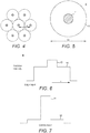
- Figure 4 again shows a similar input fibre bundle to that of Figure 1 .
- the input fibre bundles themselves are well known and comprise a central core 3 and an outer cladding region.
- This is spliced to an output fibre 6 shown in Figure 5 which differs from that of Figure 2 by having a central core 7 and a surrounding cladding 8.
- the cladding region 8 is a first region of refractive index n0
- the core 7 is a secondary region of index n1, different to n0.
- the cladding diameter is approximately equal to the outer diameter of the tapered input fibre bundle and thus is of diameter approximately 3d.
- the central core is of higher refractive index than the cladding.
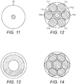
- Figure 11 also shows the output fibre of Figure 5 and Figure 12 shows this superimposed upon a cross-sectional view of the tapered input fibre, illustrating the individual input fibres 11a to 11g and the output fibre 12 having a core 13 which lies generally concentric (coaxial) with, or at least inside (or coextensive with) a central fibre 11g.
- the inner core (7, 13) acts to capture the majority of light from the central input fibre 11g and thus gives a pronounced peak 15 in the output beam profile which is shown in Figure 6 .
- a portion of the light from the outer input fibre (input ports) 11a to 11f is also captured by the central core of the output fibre.
- a profile as shown in Figure 6 or in Figure 7 for example with a central peak 15 above a plateau level 16 is obtained.
- Such a profile is beneficial for a range of laser-processing operations.
- Figure 7 shows an example of a centre input (ie where the input comes mainly or wholly from the central input fibre) and Figure 6 shows an example of an edge input, in which the majority of the input comes from the ring of fibres surrounding the central input fibre. It is seen that with a centre input a much more pronounced peak is obtained but a significant peak is still obtained with an edge input.
- a centre input a much more pronounced peak is obtained but a significant peak is still obtained with an edge input.
- Figure 8 again shows an input fibre bundle similar to that of Figure 4 .
- Figure 9 shows an output fibre 17 having an annular relatively high-index region 18.
- Figure 13 shows an annular high-index region outlet fibre similar to Figure 9
- Figure 14 shows the output fibre of Figure 13 overlapped with a tapered fibre bundle.
- this most preferably overlaps the outer fibres (11a to 11f) of the input tapered fibre bundle shown in Figure 8 . That is, the inner diameter d1 is greater than or equal to d (the diameter of an input fibre) and the outer diameter d2 of the annular region is less than or equal to 3 x d, as is shown in Figure 14 where the annulus is shown as being overlapped with the outer input fibres.
- Figure 15 shows a typical application of the invention in a material processing application.
- the laser sub units 23 shown may have an output power of up to 1.5kW and the combined beam at 26 may be up to 10kW.
- the laser source from combiner 25 is directed via coupling optics 27 onto the material to be modified 28.
- N individual fibre lasers sources 23 are coupled into the combiner 25 through their respective feed fibres 24.
- the combiner is formed by the fusion of the feed fibre 24 and the delivery fibre 26.
- the output beam profile at 28 can be controlled as described earlier in this application. Examples of the profiles are shown in figures 6, 7 and 10 .
- a further aspect of this invention is fast switching of the mode profile.
- the output beam profile at 28 can be switched.
- each laser may be switched ON or OFF, during a material processing operation, independently of the other laser, to alter or tailor the beam profile.
- the time to switch between these two profiles is limited by the response time of the control electronics for the individual lasers 23. Typically this can be of the order of tens of microseconds. This time is far faster than alternative bulk optic switching methods that have been used previously to control the beam profile. This rapid switching time enables the possibility of in process beam profile switching for optimised material processing.
- One, two or more of the N lasers may be turned ON or OFF, or their output varied, to alter the beam profile.
Landscapes
- Physics & Mathematics (AREA)
- Optics & Photonics (AREA)
- General Physics & Mathematics (AREA)
- Engineering & Computer Science (AREA)
- Plasma & Fusion (AREA)
- Electromagnetism (AREA)
- Lasers (AREA)
- Optical Couplings Of Light Guides (AREA)
Description
- This invention relates to a fibre optical laser combiner. In particular, it relates to a combiner for combining the output from several lasers into a single output fibre, and apparatus and methods for controlling the spatial beam profile emitted from that fibre.
- Many laser-processing schemes rely on beam delivery via an optical fibre. This fibre is usually radially symmetric (of circular cross-section) and has a uniform refractive index profile (otherwise known as step-index). The beam emitted from such a fibre is thus also circularly symmetric and produces a generally uniform distribution of light on a workpiece receiving a laser beam via the beam delivery optical fibre.
- For many applications it is desirable to produce tailored non-uniform light distributions on the workpiece, such as an annular profile or profiles having a central peak. Schemes are available for producing such profiles but are often complex and involve the use of free-space optics. The use of these is undesirable, particularly with high-power fibre-laser systems.
- One method of producing high power fibre laser systems is to combine the outputs from several lasers via a tapered fibre bundle, spliced to an output fibre. Each laser is delivered to the bundle via a separate input fibre, the laser beams in the separate input fibres are then combined and all their inputs exit via the same single output fibre. These are known generally as output combiners. One aspect of such a combining scheme is that, although the individual input fibres are located in close proximity to each other, the inputs are distinct while they remain in the tapered bundle. The standard output fibre collects all of the inputs and produces a uniform output as all the inputs are overlapped by the same circularly symmetric single refractive index region.
-
WO 2011/048398 discloses a system having a tapered input fibre bundle. -
WO 2005/029146 describes an optical coupler that has a bundle of multimode fibers with a few-mode fiber in its centre. Such bundle is fused at one end which is the output end for the signal that is transmitted by the few-mode fiber. To make the coupler, this output end of the bundle is aligned and spliced with a large area core double clad fiber while preserving the modal content of the feed-through. -
US 2005/0105854 discloses an optical fibre pump multiplexer in which one or more single mode few-moded or multimode fibers are incorporated into a bundle to carry input to a fiber amplifier or output from a fiber amplifier or a fiber laser. The input is at the signal wavelength, which is the wavelength where amplification or lasing occurs. Each of the fibers in the bundle is cleaved individually or as a group and fiber ends are aligned in the same plane. The fiber amplifier or fiber laser may include a double clad fiber and the other fibers of the bundle couple light for cladding pumping. The device may also include a mode filter for controlling the output mode. -
WO 2009/080039 a fiber optic combiner having an input section and an output section, separated in a longitudinal direction of the combiner by an intermediate section, where said input section comprises a plurality of N individual optical fibers wherein the core of at least one of said individual fibers extends through at least part of the intermediate section from input section to output section and Acore,n is reduced along at least a part of the intermediate section where said reduction is obtainable by removal of material from said core. Thereby improved properties of the combiner may be obtained. -
GB 2307059 - The present invention arose in an attempt to provide a combining arrangement which can produce a non-uniform, or tailored light distribution at a workpiece.
- According to the present invention in a first aspect there is an optical apparatus according to
claim 6. - The secondary regions are thereby arranged such that they provide coupling from only a subset of the input fibres.
- The first region has a diameter which is preferably equal or substantially equal to the diameter of the input fibre bundle at the splice point.
- The output fibre may be a double-clad output fibre.
- The first region may be a cladding.
- The secondary region comprises one or more annular regions.
- The input fibre bundle comprises at least one radially outer set of input fibres, and said annular region overlies said radially outer input fibres.
- The output fibre has an annular secondary region, such as a circular high-index ring that overlaps with the outer fibres of the input bundle, such that a majority of the input light is coupled directly to the annular pedestal which is formed by the high-index ring. This leads to an intensity profile of light output against the diameter which has an annular peak. This method of producing an annular beam is a robust and simple method compared to other bulk optic schemes. Furthermore, the brightness increases, typically by the ratio of the overall fibre area to the annular pedestal area. Such a profile is also beneficial for a wide range of laser processing applications.
- In a further aspect, the invention provides a method of providing a single output from a plurality of lasers according to
claim 1. The secondary regions may be an annular region or a plurality of annular regions, a combination of a central core and one or more annular regions, or other configurations where more than one high-index region is provided, which regions may be of different refractive indices. - In a further aspect, there is provided a laser system including an output combiner as described.
- In a further aspect, there is provided a method of material processing, or of tailoring a beam profile during material processing, using a method or apparatus as described.
- Embodiments of the invention will now be described, by way of example only, with reference to the accompanying schematic drawings, in which:
-
Figure 1 shows an end view of input fibre bundle; -
Figure 2 shows a matching output fibre without a secondary region; -
Figure 3 shows a plot of output intensity; -
Figure 4 shows an end view of a fibre bundle; -
Figure 5 a matching output fibre with a secondary region; -
Figure 6 shows a plot of output intensity with edge input; -
Figure 7 shows a plot of output intensity with a centre input; -
Figure 8 shows an end view of an input bundle; -
Figure 9 shows a matching output fibre a secondary region; -
Figure 10 shows a plot of output intensity; -
Figure 11 shows an output fibre similar toFigure 5 ; -
Figure 12 shows the output fibre overlapped with a tapered input fibre bundle; -
Figure 13 shows an annular high-index region output fibre similar to that ofFigure 9 ; -
Figure 14 shows the output fibre ofFigure 13 overlapped with a tapered input fibre bundle; and -
Figure 15 shows a system usable for material processing. -
Figures 1 to 3 show a previously proposed system. An input fibre bundle comprises a bundle of seven fibres comprising a firstcentral fibre 1 and sixouter fibres 2a to 2f. Each fibre has a cladding 4 (of diameter d) and acore 3. The fibre bundle is tapered in a known manner. It receives inputs from seven separate fibre lasers at a proximal end and the distal end is shown in the figure, from which the individual laser outputs are emitted via the separate fibres. This is spliced to a matching output fibre 5 typically ofcladding diameter 3d. In the output fibre, the individual outputs from the separate laser, which have been applied through the individual fibres of the fibre bundle shown inFigure 1 are combined the resulting beam is output at the output end of theoutput fibre 4.Figure 3 shows approximately the relative intensity of the output across the diameter of the output phase of the fibre and it will be seen that this is generally uniform across the entire diameter. Of course, the diagram is simplified and there may be slight variations in practice. -
Figure 4 again shows a similar input fibre bundle to that ofFigure 1 . Note that the input fibre bundles themselves are well known and comprise acentral core 3 and an outer cladding region. This is spliced to anoutput fibre 6 shown inFigure 5 which differs from that ofFigure 2 by having a central core 7 and a surroundingcladding 8. Thus, thecladding region 8 is a first region of refractive index n0, and the core 7 is a secondary region of index n1, different to n0. The cladding diameter is approximately equal to the outer diameter of the tapered input fibre bundle and thus is of diameter approximately 3d. The central core is of higher refractive index than the cladding. In one embodiment, the refractive indices are as follows:Core = 1.459 Cladding = 1.455 NA = 0.11 -
Figure 11 also shows the output fibre ofFigure 5 andFigure 12 shows this superimposed upon a cross-sectional view of the tapered input fibre, illustrating theindividual input fibres 11a to 11g and theoutput fibre 12 having a core 13 which lies generally concentric (coaxial) with, or at least inside (or coextensive with) a central fibre 11g. It is observed that the inner core (7, 13) acts to capture the majority of light from the central input fibre 11g and thus gives a pronouncedpeak 15 in the output beam profile which is shown inFigure 6 . Furthermore, it is also observed that a portion of the light from the outer input fibre (input ports) 11a to 11f is also captured by the central core of the output fibre. Thus, a profile as shown inFigure 6 or inFigure 7 for example with acentral peak 15 above aplateau level 16 is obtained. Such a profile is beneficial for a range of laser-processing operations. -
Figure 7 shows an example of a centre input (ie where the input comes mainly or wholly from the central input fibre) andFigure 6 shows an example of an edge input, in which the majority of the input comes from the ring of fibres surrounding the central input fibre. It is seen that with a centre input a much more pronounced peak is obtained but a significant peak is still obtained with an edge input. By varying the type of input and also the index and size of the central core and/or cladding different outputs can be obtained for different uses. -
Figure 8 again shows an input fibre bundle similar to that ofFigure 4 . -
Figure 9 shows anoutput fibre 17 having an annular relatively high-index region 18.Figure 13 shows an annular high-index region outlet fibre similar toFigure 9 , andFigure 14 shows the output fibre ofFigure 13 overlapped with a tapered fibre bundle. As is shown inFigure 14 , this most preferably overlaps the outer fibres (11a to 11f) of the input tapered fibre bundle shown inFigure 8 . That is, the inner diameter d1 is greater than or equal to d (the diameter of an input fibre) and the outer diameter d2 of the annular region is less than or equal to 3 x d, as is shown inFigure 14 where the annulus is shown as being overlapped with the outer input fibres. - This leads to an output profile as shown schematically in
Figure 10 having anannulus plateau 22. In such an output fibre which has an annular high-index region that overlaps with the outer fibres of the tapered input bundle, the large majority of the input light is coupled directly to this annular pedestal. The efficiency of the system tends to be very high compared with free space methods of annular beam generation. In addition, it is found that the brightness of the source actually increases (by the ratio of the overall fibre area to the annular pedestal area). -
Figure 15 shows a typical application of the invention in a material processing application. Thelaser sub units 23 shown may have an output power of up to 1.5kW and the combined beam at 26 may be up to 10kW. The laser source fromcombiner 25 is directed viacoupling optics 27 onto the material to be modified 28. - N individual
fibre lasers sources 23 are coupled into thecombiner 25 through theirrespective feed fibres 24. The combiner is formed by the fusion of thefeed fibre 24 and thedelivery fibre 26. Through the choice of refractive index profile of thedelivery fibre 26 and the orientation of thefeed fibres 24 relative to this fibre the output beam profile at 28 can be controlled as described earlier in this application. Examples of the profiles are shown infigures 6, 7 and10 . - A further aspect of this invention is fast switching of the mode profile. By individually addressing/controlling the
component lasers 23 the output beam profile at 28 can be switched. For example using the combiner described infigures 4 and 5 excitation of all the lasers produces a broad near flat top profile ideal for welding and thick section cutting. Excitation of just the central port laser on the other hand produces a narrow beam profile which is ideal for thin section cutting. Thus, each laser may be switched ON or OFF, during a material processing operation, independently of the other laser, to alter or tailor the beam profile. The time to switch between these two profiles is limited by the response time of the control electronics for theindividual lasers 23. Typically this can be of the order of tens of microseconds. This time is far faster than alternative bulk optic switching methods that have been used previously to control the beam profile. This rapid switching time enables the possibility of in process beam profile switching for optimised material processing. - One, two or more of the N lasers may be turned ON or OFF, or their output varied, to alter the beam profile.
- The embodiments shown and described are illustrative only and other embodiments may be used which lie within the scope of the claims. Some may have a central core and one or more annular or other shape regions of relatively high-index compared to the rest of the output fibre. Other shapes may be used for different beam profiles.
Claims (6)
- A method of providing a single output from a plurality of lasers, comprising providing an input fibre bundle (11g, 11a-11f) having a plurality of input fibres receiving laser outputs from each of a plurality of lasers (Laser 1, Laser 2), and splicing the bundle, at a splice point, to a single output fibre (6,17,26); said output fibre comprising a first region (8) with refractive index n0 and diameter equal to or greater than the input fibre bundle diameter and also includes one or more secondary regions (7,18) within the first region, the secondary regions each having refractive index that differs from n0, characterised by each of the secondary regions not overlying all of the input fibres, wherein the secondary region comprises an annular high-index region (18) the input fibre bundle (11g,11a-11f) comprises a central fibre(11g) and a plurality of radially outer fibres (11a-11f) wherein the annular high-index region (18) overlies the radially outer fibres (11a-11f) but does not overlie the central fibre (11g) and; the method further comprising controlling the outputs of each of the plurality of lasers (Laser 1, Laser 2) independently to select or adjust the beam profile of a beam output from the output fibre (6,17,26).
- A method as claimed in Claim 1, wherein the lasers are fibre lasers.
- A method as claimed in Claim 1, wherein the annular high-index region (18) has a diameter which is greater than or equal to the diameter of one of the input fibres (11g,11a-11f) and less than or equal to 3 times the diameter of one of the input fibres.
- A method as claimed in Claim 3, wherein the input fibres (11g, 11a-11f) are all of the same diameter.
- A method as claimed in any of Claims 1 to 4, used in a material processing operation.
- Optical apparatus, comprising an optical combiner (25), comprising a bundle of input fibres (11g, 11a-11f) spliced to an output fibre (6,17,26) said output fibre comprising a first region (8) with refractive index n0 and diameter equal to or greater than the input fibre bundle diameter and one or more secondary regions (7,18) within the first region, the secondary regions each having refractive index that differs from n0, characterised by each of the secondary regions not overlying all of the input fibres wherein the secondary region comprises at least one annular high-index region (18), the input fibre bundle comprising an inner fibre (11g) and at least one radially outer set of input fibres (11a-11f) and wherein said annular region (18) overlies said radially outer set of input fibres but does not overlie said inner fibre, and by a plurality of lasers (Laser 1, Laser 2), each laser arranged to provide a laser output to a respective input fibre, wherein the laser outputs of the lasers are independently controllable to select or adjust the beam profile of a laser beam output from the output fibre (6,17,26).
Priority Applications (1)
| Application Number | Priority Date | Filing Date | Title |
|---|---|---|---|
| PL14701616T PL2951625T3 (en) | 2013-01-31 | 2014-01-27 | Fibre optical laser combiner |
Applications Claiming Priority (2)
| Application Number | Priority Date | Filing Date | Title |
|---|---|---|---|
| GB1301745.4A GB2510370A (en) | 2013-01-31 | 2013-01-31 | Fibre Optical Laser Combiner |
| PCT/GB2014/050203 WO2014118516A1 (en) | 2013-01-31 | 2014-01-27 | Fibre optical laser combiner |
Publications (2)
| Publication Number | Publication Date |
|---|---|
| EP2951625A1 EP2951625A1 (en) | 2015-12-09 |
| EP2951625B1 true EP2951625B1 (en) | 2018-04-04 |
Family
ID=47988501
Family Applications (1)
| Application Number | Title | Priority Date | Filing Date |
|---|---|---|---|
| EP14701616.6A Active EP2951625B1 (en) | 2013-01-31 | 2014-01-27 | Fibre optical laser combiner |
Country Status (8)
| Country | Link |
|---|---|
| US (1) | US9620925B2 (en) |
| EP (1) | EP2951625B1 (en) |
| CN (1) | CN104969104B (en) |
| ES (1) | ES2670976T3 (en) |
| GB (1) | GB2510370A (en) |
| HU (1) | HUE037968T2 (en) |
| PL (1) | PL2951625T3 (en) |
| WO (1) | WO2014118516A1 (en) |
Families Citing this family (24)
| Publication number | Priority date | Publication date | Assignee | Title |
|---|---|---|---|---|
| PL3180823T3 (en) * | 2014-08-13 | 2022-08-08 | Ipg Photonics Corporation | Multibeam fiber laser system, method and use |
| US10807190B2 (en) | 2015-06-09 | 2020-10-20 | Corelase Oy | Laser processing apparatus and method and an optical component therefor |
| CA3026330C (en) | 2016-07-15 | 2020-11-24 | Corelase Oy | Laser processing apparatus and method |
| CN110087817B (en) * | 2016-12-08 | 2022-05-17 | 可利雷斯股份有限公司 | Laser processing equipment and method |
| CN107065215B (en) * | 2017-04-17 | 2019-06-21 | 西安中科中美激光科技有限公司 | Expansible array fibre output laser |
| JP6456427B2 (en) * | 2017-04-28 | 2019-01-23 | 株式会社フジクラ | Combiner and laser device |
| US11850679B2 (en) * | 2017-12-29 | 2023-12-26 | Corelase Oy | Laser processing apparatus and method |
| GB201801560D0 (en) * | 2018-01-30 | 2018-03-14 | Spi Lasers Uk Ltd | Apparatus and method for controlling the spatial beam profile of laser radiation |
| GB201801796D0 (en) * | 2018-02-02 | 2018-03-21 | Spi Lasers Uk Ltd | Apparatus and method for laser processing a material |
| US11114809B2 (en) * | 2018-02-22 | 2021-09-07 | Lumentum Operations Llc | Fiber optic device operational monitoring |
| CN108445640A (en) * | 2018-02-28 | 2018-08-24 | 北京控制工程研究所 | A kind of coaxial uniform illumination system of relative pose vision measurement sensor |
| CN108873359B (en) * | 2018-08-15 | 2023-12-29 | 南通极瓦特激光科技有限公司 | Water-cooled light spot adjustable optical cable and light spot adjusting method thereof |
| WO2020117816A1 (en) * | 2018-12-03 | 2020-06-11 | Ipg Photonics Corporation | Ultrahigh fiber laser system with controllable output beam intensity profile |
| JP7502073B2 (en) * | 2020-04-16 | 2024-06-18 | 古河電気工業株式会社 | Laser Processing Equipment |
| US12341320B2 (en) * | 2020-05-26 | 2025-06-24 | Fujikura Ltd. | Optical combiner and laser apparatus |
| WO2021240880A1 (en) * | 2020-05-26 | 2021-12-02 | 株式会社フジクラ | Optical combiner and laser device |
| WO2021241545A1 (en) * | 2020-05-26 | 2021-12-02 | 株式会社フジクラ | Optical combiner and laser device |
| US20220009027A1 (en) * | 2020-07-07 | 2022-01-13 | Panasonic Intellectual Property Management Co. Ltd | Step-core fiber structures and methods for altering beam shape and intensity |
| DE102020128186A1 (en) | 2020-10-27 | 2022-04-28 | Trumpf Werkzeugmaschinen Gmbh + Co. Kg | Process and device for laser cutting using a laser beam guided in a multi-core fiber and the associated computer program product |
| JP7763071B2 (en) * | 2020-10-27 | 2025-10-31 | 古河電気工業株式会社 | Combiner and Light Source |
| CN112310793A (en) * | 2020-10-30 | 2021-02-02 | 山东海富光子科技股份有限公司 | High-power all-fiber laser beam combiner with adjustable output beam shape |
| DE102022110078A1 (en) | 2022-04-26 | 2023-10-26 | Trumpf Laser Gmbh | Device and method for modifying the beam profile of a laser beam |
| CN117192706B (en) * | 2023-10-23 | 2024-03-19 | 中国人民解放军国防科技大学 | Supercontinuum laser system that realizes hollow beam emission |
| DE102024109598A1 (en) * | 2024-04-05 | 2025-10-09 | TRUMPF Laser- und Systemtechnik SE | Method and device for laser welding |
Family Cites Families (16)
| Publication number | Priority date | Publication date | Assignee | Title |
|---|---|---|---|---|
| US3777150A (en) | 1972-07-17 | 1973-12-04 | Bell Telephone Labor Inc | Mode detection and delay equalization in multimode optical fiber transmission systems |
| JPH09184941A (en) * | 1995-10-30 | 1997-07-15 | Fuji Electric Co Ltd | Optical star coupler |
| US5742717A (en) * | 1995-10-30 | 1998-04-21 | Fuji Electric Co., Ltd. | Optical star coupler |
| US5864644A (en) * | 1997-07-21 | 1999-01-26 | Lucent Technologies Inc. | Tapered fiber bundles for coupling light into and out of cladding-pumped fiber devices |
| US6501884B1 (en) | 2000-06-30 | 2002-12-31 | Lucent Technologies Inc. | Article comprising means for mode-selective launch into a multimode optical fiber, and method for a mode-selective launch |
| US20030072525A1 (en) * | 2001-06-29 | 2003-04-17 | Theodore Sjodin | Multi-mode fiber bandwidth enhancement using an optical fiber coupler |
| CA2441918C (en) * | 2003-09-19 | 2010-06-08 | Itf Technologies Optiques Inc./Itf Optical Technologies Inc. | Optical coupler comprising multimode fibers and method of making the same |
| US7046875B2 (en) * | 2003-10-29 | 2006-05-16 | Itf Technologies Optiques Inc. | Optical coupler comprising multimode fibers and method of making the same |
| US7016573B2 (en) * | 2003-11-13 | 2006-03-21 | Imra America, Inc. | Optical fiber pump multiplexer |
| GB0328370D0 (en) | 2003-12-05 | 2004-01-14 | Southampton Photonics Ltd | Apparatus for providing optical radiation |
| US7409128B2 (en) * | 2005-06-29 | 2008-08-05 | Lucent Technologies Inc. | Pumping arrangement for fiber amplifiers with reduced reflective feedback |
| WO2009077637A1 (en) | 2007-12-14 | 2009-06-25 | Corelase Oy | Method and device relating to optical fibers |
| WO2009080039A1 (en) | 2007-12-20 | 2009-07-02 | Crystal Fibre A/S | Optical combiner and method of producing the same |
| US9946014B2 (en) * | 2010-03-16 | 2018-04-17 | Ofs Fitel, Llc | Techniques and devices for low-loss coupling to a multicore fiber |
| DE102010003750A1 (en) | 2010-04-08 | 2011-10-13 | Trumpf Laser- Und Systemtechnik Gmbh | Method and arrangement for changing the beam profile characteristic of a laser beam by means of a multiple-clad fiber |
| US9698557B2 (en) * | 2015-03-09 | 2017-07-04 | Fujikura Ltd. | Optical fiber for amplification and optical fiber amplifier using the same |
-
2013
- 2013-01-31 GB GB1301745.4A patent/GB2510370A/en not_active Withdrawn
-
2014
- 2014-01-27 US US14/764,295 patent/US9620925B2/en active Active
- 2014-01-27 PL PL14701616T patent/PL2951625T3/en unknown
- 2014-01-27 ES ES14701616.6T patent/ES2670976T3/en active Active
- 2014-01-27 HU HUE14701616A patent/HUE037968T2/en unknown
- 2014-01-27 CN CN201480006534.3A patent/CN104969104B/en active Active
- 2014-01-27 WO PCT/GB2014/050203 patent/WO2014118516A1/en not_active Ceased
- 2014-01-27 EP EP14701616.6A patent/EP2951625B1/en active Active
Also Published As
| Publication number | Publication date |
|---|---|
| US20150372444A1 (en) | 2015-12-24 |
| GB2510370A (en) | 2014-08-06 |
| GB201301745D0 (en) | 2013-03-20 |
| ES2670976T3 (en) | 2018-06-04 |
| PL2951625T3 (en) | 2018-08-31 |
| WO2014118516A1 (en) | 2014-08-07 |
| HUE037968T2 (en) | 2018-09-28 |
| CN104969104A (en) | 2015-10-07 |
| CN104969104B (en) | 2018-12-04 |
| US9620925B2 (en) | 2017-04-11 |
| EP2951625A1 (en) | 2015-12-09 |
Similar Documents
| Publication | Publication Date | Title |
|---|---|---|
| EP2951625B1 (en) | Fibre optical laser combiner | |
| US20240139866A1 (en) | Method and arrangement for generating a laser beam having a differing beam profile characteristic by a multi-clad fiber | |
| US8472765B2 (en) | Fiber based laser combiners | |
| CN113169505B (en) | Ultra-high intensity fiber laser system with controllable output beam intensity profile | |
| US9494738B1 (en) | Single mode fiber combiners | |
| US10942311B2 (en) | Optical device | |
| US9211681B2 (en) | Fiber Based Laser Combiners | |
| US7460755B2 (en) | Method and apparatus for combining laser light | |
| WO2013165548A2 (en) | Multi-function beam delivery fibers and related system and method | |
| EP4039401B1 (en) | Optical combiner and laser device | |
| US9268095B2 (en) | All-fiber low mode beam combiner for high power and high beam quality | |
| US11133638B2 (en) | Apparatus for combining laser beams in optical fibers, and corresponding method | |
| KR20250027750A (en) | Device for laser processing of materials | |
| JP3939816B2 (en) | Laser equipment | |
| JP7402024B2 (en) | laser equipment | |
| US20250372934A1 (en) | Ultrahigh fiber laser system with controllable output beam intensity profile | |
| WO2004068204A1 (en) | Method and apparatus for coupling light | |
| KR20260003821A (en) | Engineered divergence distributions | |
| US20260057732A1 (en) | Engineered divergence distributions |
Legal Events
| Date | Code | Title | Description |
|---|---|---|---|
| PUAI | Public reference made under article 153(3) epc to a published international application that has entered the european phase |
Free format text: ORIGINAL CODE: 0009012 |
|
| 17P | Request for examination filed |
Effective date: 20150729 |
|
| AK | Designated contracting states |
Kind code of ref document: A1 Designated state(s): AL AT BE BG CH CY CZ DE DK EE ES FI FR GB GR HR HU IE IS IT LI LT LU LV MC MK MT NL NO PL PT RO RS SE SI SK SM TR |
|
| AX | Request for extension of the european patent |
Extension state: BA ME |
|
| DAX | Request for extension of the european patent (deleted) | ||
| 17Q | First examination report despatched |
Effective date: 20160805 |
|
| STAA | Information on the status of an ep patent application or granted ep patent |
Free format text: STATUS: EXAMINATION IS IN PROGRESS |
|
| REG | Reference to a national code |
Ref country code: DE Ref legal event code: R079 Ref document number: 602014023261 Country of ref document: DE Free format text: PREVIOUS MAIN CLASS: G02B0006255000 Ipc: G02B0006040000 |
|
| GRAP | Despatch of communication of intention to grant a patent |
Free format text: ORIGINAL CODE: EPIDOSNIGR1 |
|
| STAA | Information on the status of an ep patent application or granted ep patent |
Free format text: STATUS: GRANT OF PATENT IS INTENDED |
|
| RIC1 | Information provided on ipc code assigned before grant |
Ipc: H01S 3/10 20060101ALI20171110BHEP Ipc: G02B 6/04 20060101AFI20171110BHEP Ipc: H01S 3/23 20060101ALI20171110BHEP Ipc: G02B 27/09 20060101ALI20171110BHEP Ipc: G02B 6/43 20060101ALI20171110BHEP Ipc: G02B 6/28 20060101ALI20171110BHEP Ipc: G02B 6/255 20060101ALI20171110BHEP Ipc: H01S 3/067 20060101ALI20171110BHEP |
|
| INTG | Intention to grant announced |
Effective date: 20171201 |
|
| GRAS | Grant fee paid |
Free format text: ORIGINAL CODE: EPIDOSNIGR3 |
|
| GRAA | (expected) grant |
Free format text: ORIGINAL CODE: 0009210 |
|
| STAA | Information on the status of an ep patent application or granted ep patent |
Free format text: STATUS: THE PATENT HAS BEEN GRANTED |
|
| AK | Designated contracting states |
Kind code of ref document: B1 Designated state(s): AL AT BE BG CH CY CZ DE DK EE ES FI FR GB GR HR HU IE IS IT LI LT LU LV MC MK MT NL NO PL PT RO RS SE SI SK SM TR |
|
| REG | Reference to a national code |
Ref country code: GB Ref legal event code: FG4D |
|
| REG | Reference to a national code |
Ref country code: CH Ref legal event code: EP |
|
| REG | Reference to a national code |
Ref country code: AT Ref legal event code: REF Ref document number: 986184 Country of ref document: AT Kind code of ref document: T Effective date: 20180415 |
|
| REG | Reference to a national code |
Ref country code: IE Ref legal event code: FG4D |
|
| REG | Reference to a national code |
Ref country code: DE Ref legal event code: R096 Ref document number: 602014023261 Country of ref document: DE |
|
| REG | Reference to a national code |
Ref country code: NL Ref legal event code: FP |
|
| REG | Reference to a national code |
Ref country code: ES Ref legal event code: FG2A Ref document number: 2670976 Country of ref document: ES Kind code of ref document: T3 Effective date: 20180604 |
|
| REG | Reference to a national code |
Ref country code: RO Ref legal event code: EPE |
|
| REG | Reference to a national code |
Ref country code: LT Ref legal event code: MG4D |
|
| REG | Reference to a national code |
Ref country code: HU Ref legal event code: AG4A Ref document number: E037968 Country of ref document: HU |
|
| PG25 | Lapsed in a contracting state [announced via postgrant information from national office to epo] |
Ref country code: SE Free format text: LAPSE BECAUSE OF FAILURE TO SUBMIT A TRANSLATION OF THE DESCRIPTION OR TO PAY THE FEE WITHIN THE PRESCRIBED TIME-LIMIT Effective date: 20180404 Ref country code: LT Free format text: LAPSE BECAUSE OF FAILURE TO SUBMIT A TRANSLATION OF THE DESCRIPTION OR TO PAY THE FEE WITHIN THE PRESCRIBED TIME-LIMIT Effective date: 20180404 Ref country code: NO Free format text: LAPSE BECAUSE OF FAILURE TO SUBMIT A TRANSLATION OF THE DESCRIPTION OR TO PAY THE FEE WITHIN THE PRESCRIBED TIME-LIMIT Effective date: 20180704 Ref country code: AL Free format text: LAPSE BECAUSE OF FAILURE TO SUBMIT A TRANSLATION OF THE DESCRIPTION OR TO PAY THE FEE WITHIN THE PRESCRIBED TIME-LIMIT Effective date: 20180404 Ref country code: BG Free format text: LAPSE BECAUSE OF FAILURE TO SUBMIT A TRANSLATION OF THE DESCRIPTION OR TO PAY THE FEE WITHIN THE PRESCRIBED TIME-LIMIT Effective date: 20180704 |
|
| PG25 | Lapsed in a contracting state [announced via postgrant information from national office to epo] |
Ref country code: HR Free format text: LAPSE BECAUSE OF FAILURE TO SUBMIT A TRANSLATION OF THE DESCRIPTION OR TO PAY THE FEE WITHIN THE PRESCRIBED TIME-LIMIT Effective date: 20180404 Ref country code: RS Free format text: LAPSE BECAUSE OF FAILURE TO SUBMIT A TRANSLATION OF THE DESCRIPTION OR TO PAY THE FEE WITHIN THE PRESCRIBED TIME-LIMIT Effective date: 20180404 Ref country code: LV Free format text: LAPSE BECAUSE OF FAILURE TO SUBMIT A TRANSLATION OF THE DESCRIPTION OR TO PAY THE FEE WITHIN THE PRESCRIBED TIME-LIMIT Effective date: 20180404 Ref country code: GR Free format text: LAPSE BECAUSE OF FAILURE TO SUBMIT A TRANSLATION OF THE DESCRIPTION OR TO PAY THE FEE WITHIN THE PRESCRIBED TIME-LIMIT Effective date: 20180705 |
|
| PG25 | Lapsed in a contracting state [announced via postgrant information from national office to epo] |
Ref country code: PT Free format text: LAPSE BECAUSE OF FAILURE TO SUBMIT A TRANSLATION OF THE DESCRIPTION OR TO PAY THE FEE WITHIN THE PRESCRIBED TIME-LIMIT Effective date: 20180806 |
|
| REG | Reference to a national code |
Ref country code: DE Ref legal event code: R097 Ref document number: 602014023261 Country of ref document: DE |
|
| PG25 | Lapsed in a contracting state [announced via postgrant information from national office to epo] |
Ref country code: EE Free format text: LAPSE BECAUSE OF FAILURE TO SUBMIT A TRANSLATION OF THE DESCRIPTION OR TO PAY THE FEE WITHIN THE PRESCRIBED TIME-LIMIT Effective date: 20180404 Ref country code: DK Free format text: LAPSE BECAUSE OF FAILURE TO SUBMIT A TRANSLATION OF THE DESCRIPTION OR TO PAY THE FEE WITHIN THE PRESCRIBED TIME-LIMIT Effective date: 20180404 Ref country code: SK Free format text: LAPSE BECAUSE OF FAILURE TO SUBMIT A TRANSLATION OF THE DESCRIPTION OR TO PAY THE FEE WITHIN THE PRESCRIBED TIME-LIMIT Effective date: 20180404 |
|
| PLBE | No opposition filed within time limit |
Free format text: ORIGINAL CODE: 0009261 |
|
| STAA | Information on the status of an ep patent application or granted ep patent |
Free format text: STATUS: NO OPPOSITION FILED WITHIN TIME LIMIT |
|
| PG25 | Lapsed in a contracting state [announced via postgrant information from national office to epo] |
Ref country code: SM Free format text: LAPSE BECAUSE OF FAILURE TO SUBMIT A TRANSLATION OF THE DESCRIPTION OR TO PAY THE FEE WITHIN THE PRESCRIBED TIME-LIMIT Effective date: 20180404 |
|
| 26N | No opposition filed |
Effective date: 20190107 |
|
| PG25 | Lapsed in a contracting state [announced via postgrant information from national office to epo] |
Ref country code: SI Free format text: LAPSE BECAUSE OF FAILURE TO SUBMIT A TRANSLATION OF THE DESCRIPTION OR TO PAY THE FEE WITHIN THE PRESCRIBED TIME-LIMIT Effective date: 20180404 |
|
| PG25 | Lapsed in a contracting state [announced via postgrant information from national office to epo] |
Ref country code: MC Free format text: LAPSE BECAUSE OF FAILURE TO SUBMIT A TRANSLATION OF THE DESCRIPTION OR TO PAY THE FEE WITHIN THE PRESCRIBED TIME-LIMIT Effective date: 20180404 |
|
| REG | Reference to a national code |
Ref country code: CH Ref legal event code: PL |
|
| PG25 | Lapsed in a contracting state [announced via postgrant information from national office to epo] |
Ref country code: LU Free format text: LAPSE BECAUSE OF NON-PAYMENT OF DUE FEES Effective date: 20190127 |
|
| REG | Reference to a national code |
Ref country code: BE Ref legal event code: MM Effective date: 20190131 |
|
| REG | Reference to a national code |
Ref country code: IE Ref legal event code: MM4A |
|
| PG25 | Lapsed in a contracting state [announced via postgrant information from national office to epo] |
Ref country code: BE Free format text: LAPSE BECAUSE OF NON-PAYMENT OF DUE FEES Effective date: 20190131 |
|
| PG25 | Lapsed in a contracting state [announced via postgrant information from national office to epo] |
Ref country code: LI Free format text: LAPSE BECAUSE OF NON-PAYMENT OF DUE FEES Effective date: 20190131 Ref country code: CH Free format text: LAPSE BECAUSE OF NON-PAYMENT OF DUE FEES Effective date: 20190131 |
|
| PG25 | Lapsed in a contracting state [announced via postgrant information from national office to epo] |
Ref country code: IE Free format text: LAPSE BECAUSE OF NON-PAYMENT OF DUE FEES Effective date: 20190127 |
|
| PG25 | Lapsed in a contracting state [announced via postgrant information from national office to epo] |
Ref country code: MT Free format text: LAPSE BECAUSE OF NON-PAYMENT OF DUE FEES Effective date: 20190127 |
|
| PG25 | Lapsed in a contracting state [announced via postgrant information from national office to epo] |
Ref country code: CY Free format text: LAPSE BECAUSE OF FAILURE TO SUBMIT A TRANSLATION OF THE DESCRIPTION OR TO PAY THE FEE WITHIN THE PRESCRIBED TIME-LIMIT Effective date: 20180404 |
|
| PG25 | Lapsed in a contracting state [announced via postgrant information from national office to epo] |
Ref country code: IS Free format text: LAPSE BECAUSE OF FAILURE TO SUBMIT A TRANSLATION OF THE DESCRIPTION OR TO PAY THE FEE WITHIN THE PRESCRIBED TIME-LIMIT Effective date: 20180804 |
|
| REG | Reference to a national code |
Ref country code: AT Ref legal event code: UEP Ref document number: 986184 Country of ref document: AT Kind code of ref document: T Effective date: 20180404 |
|
| PG25 | Lapsed in a contracting state [announced via postgrant information from national office to epo] |
Ref country code: MK Free format text: LAPSE BECAUSE OF FAILURE TO SUBMIT A TRANSLATION OF THE DESCRIPTION OR TO PAY THE FEE WITHIN THE PRESCRIBED TIME-LIMIT Effective date: 20180404 |
|
| REG | Reference to a national code |
Ref country code: DE Ref legal event code: R081 Ref document number: 602014023261 Country of ref document: DE Owner name: TRUMPF LASER UK LTD., HEDGE END, GB Free format text: FORMER OWNER: SPI LASERS UK LIMITED, SOUTHAMPTON, GB |
|
| REG | Reference to a national code |
Ref country code: NL Ref legal event code: HC Owner name: TRUMPF LASER UK LIMITED; GB Free format text: DETAILS ASSIGNMENT: CHANGE OF OWNER(S), CHANGE OF OWNER(S) NAME; FORMER OWNER NAME: SPI LASERS UK LIMITED Effective date: 20241118 |
|
| REG | Reference to a national code |
Ref country code: HU Ref legal event code: HC9C Owner name: TRUMPF LASER UK LIMITED, GB Free format text: FORMER OWNER(S): SPI LASERS UK LIMITED, GB |
|
| REG | Reference to a national code |
Ref country code: ES Ref legal event code: PC2A Owner name: TRUMPF LASER UK LIMITED Effective date: 20250210 |
|
| REG | Reference to a national code |
Ref country code: AT Ref legal event code: HC Ref document number: 986184 Country of ref document: AT Kind code of ref document: T Owner name: TRUMPF LASER UK LIMITED, GB Effective date: 20250120 |
|
| PGFP | Annual fee paid to national office [announced via postgrant information from national office to epo] |
Ref country code: NL Payment date: 20260121 Year of fee payment: 13 |
|
| PGFP | Annual fee paid to national office [announced via postgrant information from national office to epo] |
Ref country code: HU Payment date: 20260123 Year of fee payment: 13 |
|
| PGFP | Annual fee paid to national office [announced via postgrant information from national office to epo] |
Ref country code: GB Payment date: 20260123 Year of fee payment: 13 |
|
| PGFP | Annual fee paid to national office [announced via postgrant information from national office to epo] |
Ref country code: ES Payment date: 20260227 Year of fee payment: 13 |
|
| PGFP | Annual fee paid to national office [announced via postgrant information from national office to epo] |
Ref country code: DE Payment date: 20260121 Year of fee payment: 13 |
|
| PGFP | Annual fee paid to national office [announced via postgrant information from national office to epo] |
Ref country code: AT Payment date: 20260122 Year of fee payment: 13 |
|
| PGFP | Annual fee paid to national office [announced via postgrant information from national office to epo] |
Ref country code: RO Payment date: 20260121 Year of fee payment: 13 Ref country code: FI Payment date: 20260129 Year of fee payment: 13 Ref country code: IT Payment date: 20260123 Year of fee payment: 13 |
|
| PGFP | Annual fee paid to national office [announced via postgrant information from national office to epo] |
Ref country code: FR Payment date: 20260123 Year of fee payment: 13 |
|
| PGFP | Annual fee paid to national office [announced via postgrant information from national office to epo] |
Ref country code: TR Payment date: 20260122 Year of fee payment: 13 |
|
| PGFP | Annual fee paid to national office [announced via postgrant information from national office to epo] |
Ref country code: CZ Payment date: 20260120 Year of fee payment: 13 |
|
| PGFP | Annual fee paid to national office [announced via postgrant information from national office to epo] |
Ref country code: PL Payment date: 20260105 Year of fee payment: 13 |