EP2951106B1 - Electrical protector - Google Patents
Electrical protector Download PDFInfo
- Publication number
- EP2951106B1 EP2951106B1 EP14701398.1A EP14701398A EP2951106B1 EP 2951106 B1 EP2951106 B1 EP 2951106B1 EP 14701398 A EP14701398 A EP 14701398A EP 2951106 B1 EP2951106 B1 EP 2951106B1
- Authority
- EP
- European Patent Office
- Prior art keywords
- cap
- insert
- sealant
- protector
- contemplated
- Prior art date
- Legal status (The legal status is an assumption and is not a legal conclusion. Google has not performed a legal analysis and makes no representation as to the accuracy of the status listed.)
- Active
Links
Images








Classifications
-
- B—PERFORMING OPERATIONS; TRANSPORTING
- B64—AIRCRAFT; AVIATION; COSMONAUTICS
- B64D—EQUIPMENT FOR FITTING IN OR TO AIRCRAFT; FLIGHT SUITS; PARACHUTES; ARRANGEMENT OR MOUNTING OF POWER PLANTS OR PROPULSION TRANSMISSIONS IN AIRCRAFT
- B64D37/00—Arrangements in connection with fuel supply for power plant
- B64D37/32—Safety measures not otherwise provided for, e.g. preventing explosive conditions
-
- B—PERFORMING OPERATIONS; TRANSPORTING
- B64—AIRCRAFT; AVIATION; COSMONAUTICS
- B64D—EQUIPMENT FOR FITTING IN OR TO AIRCRAFT; FLIGHT SUITS; PARACHUTES; ARRANGEMENT OR MOUNTING OF POWER PLANTS OR PROPULSION TRANSMISSIONS IN AIRCRAFT
- B64D45/00—Aircraft indicators or protectors not otherwise provided for
- B64D45/02—Lightning protectors; Static dischargers
-
- F—MECHANICAL ENGINEERING; LIGHTING; HEATING; WEAPONS; BLASTING
- F16—ENGINEERING ELEMENTS AND UNITS; GENERAL MEASURES FOR PRODUCING AND MAINTAINING EFFECTIVE FUNCTIONING OF MACHINES OR INSTALLATIONS; THERMAL INSULATION IN GENERAL
- F16B—DEVICES FOR FASTENING OR SECURING CONSTRUCTIONAL ELEMENTS OR MACHINE PARTS TOGETHER, e.g. NAILS, BOLTS, CIRCLIPS, CLAMPS, CLIPS OR WEDGES; JOINTS OR JOINTING
- F16B37/00—Nuts or like thread-engaging members
- F16B37/14—Cap nuts; Nut caps or bolt caps
-
- F—MECHANICAL ENGINEERING; LIGHTING; HEATING; WEAPONS; BLASTING
- F16—ENGINEERING ELEMENTS AND UNITS; GENERAL MEASURES FOR PRODUCING AND MAINTAINING EFFECTIVE FUNCTIONING OF MACHINES OR INSTALLATIONS; THERMAL INSULATION IN GENERAL
- F16B—DEVICES FOR FASTENING OR SECURING CONSTRUCTIONAL ELEMENTS OR MACHINE PARTS TOGETHER, e.g. NAILS, BOLTS, CIRCLIPS, CLAMPS, CLIPS OR WEDGES; JOINTS OR JOINTING
- F16B11/00—Connecting constructional elements or machine parts by sticking or pressing them together, e.g. cold pressure welding
- F16B11/006—Connecting constructional elements or machine parts by sticking or pressing them together, e.g. cold pressure welding by gluing
-
- F—MECHANICAL ENGINEERING; LIGHTING; HEATING; WEAPONS; BLASTING
- F16—ENGINEERING ELEMENTS AND UNITS; GENERAL MEASURES FOR PRODUCING AND MAINTAINING EFFECTIVE FUNCTIONING OF MACHINES OR INSTALLATIONS; THERMAL INSULATION IN GENERAL
- F16B—DEVICES FOR FASTENING OR SECURING CONSTRUCTIONAL ELEMENTS OR MACHINE PARTS TOGETHER, e.g. NAILS, BOLTS, CIRCLIPS, CLAMPS, CLIPS OR WEDGES; JOINTS OR JOINTING
- F16B33/00—Features common to bolt and nut
- F16B33/004—Sealing; Insulation
-
- Y—GENERAL TAGGING OF NEW TECHNOLOGICAL DEVELOPMENTS; GENERAL TAGGING OF CROSS-SECTIONAL TECHNOLOGIES SPANNING OVER SEVERAL SECTIONS OF THE IPC; TECHNICAL SUBJECTS COVERED BY FORMER USPC CROSS-REFERENCE ART COLLECTIONS [XRACs] AND DIGESTS
- Y10—TECHNICAL SUBJECTS COVERED BY FORMER USPC
- Y10T—TECHNICAL SUBJECTS COVERED BY FORMER US CLASSIFICATION
- Y10T29/00—Metal working
- Y10T29/49—Method of mechanical manufacture
- Y10T29/49229—Prime mover or fluid pump making
Definitions
- the present invention concerns a device that is applied to a nut, bolt, or other protruding structure to insulate the structure.
- the present invention concerns the design of a structure that establishes an electrical barrier between the protruding structure and its surrounding environment. More specifically, the present invention provides a device that insulates a nut, bolt, or other protruding structure from the surrounding environment in the event that there is a proximate lightning strike ( i.e ., Zone 2 protection).
- One known method of sealing protruding structures is to coat the structures with a suitable sealant.
- Another method involves creating a cup from the sealant by allowing a thin layer of the sealant to cure. The remaining volume of the cup is then filled with additional sealant before being applied to the protruding structure in the fuel tank of the aircraft.
- U.S. Patent No. 4,382,049 (hereinafter "the '049 Patent") describes a lightning spark isolation barrier that includes a fastener 10 that is attached to a surface 12 via rivets 20.
- the fastener 10 is located on the inner surface of an exterior skin of an aircraft in a critical fuel vapor area.
- the fastener 10 is partially surrounded by a cap 22 that is first filled with a dielectric isolation material 24 in an uncured, viscous, or plastic form.
- the cap 22 is made of plastic.
- the '049 Patent at col. 3, lines 14-16.
- U.S. Patent No. 4,905,931 (hereinafter "the '931 Patent") describes an arc suppression apparatus that is positioned around a fastener.
- the fastener 10 attaches two composite members 20, 22 together.
- the '931 Patent at col. 2, lines 33-34.
- the '931 Patent describes a plastic cap 50 that is affixed to the composite member 22 at the surface 19 and is placed over the end of the fastener to enclose a volume of air gases 41 in the void 40.
- a polysulfide rubber sealant 50 is provided outside of and around the cap 50 to ensure that an airtight seal around the void 40 exists at all times during the lifetime of the aircraft.
- the '931 Patent at col. 3, lines 20-24. The '931 Patent at col. 3, lines 20-24.
- U.S. Patent Application Publication No. 2012/0074257 (hereinafter "the '257 Application”) describes a lightning-resistant fastener, cap, and method of mounting the lightning-resistant fastener.
- the '257 Application describes that a collar 26 is screwed onto a fastener main body 25. (The '257 Application at paragraph [0040].) The collar 26 and screw 25 are encased beneath a cap 30 made from an insulating resin. (The '257 Application at paragraph [0046].) The cap 30 is filled with a sealant 34. (The '257 Application at paragraph [0052].) The cap 30 may be pre-filled with the sealant 34 in an uncured state. (The '257 Application at paragraph [0053].)
- a further protective device is known from WO 97/29289 comprising a closed cap which is pre-filled with sealant, further comprising an insert defining a ring and an insert wall and at least one protrusion that extends inwardly from an interior surface of the insert wall toward a nut/bolt and is adapted to engage the nut/bolt.
- the present invention addresses one or more of the deficiencies noted with respect to the prior art.
- the present invention provides an electrical protector with a central axis that includes a cap defining a top and a downwardly extending cap wall adapted for receiving a sealant, an insert defining a ring and an upwardly extending insert wall, a plurality of castellations for maintaining a gap between the ring and a surface on which the electrical protector sits, and at least one protrusion extending inwardly from an interior surface of the insert wall toward the central axis.
- the cap wall connects to the insert wall.
- the at least one protrusion is adapted to engage a structure, thereby securing the lightning strike protector onto the structure.
- the cap wall is frusto-conically shaped.
- the insert wall is frusto-conically shaped.
- the sealant is polysulfide.
- cap wall and the insert wall may engage one another by an interference fit.
- the structure is at least one of a nut and a bolt.
- the structure may be located inside of a fuel tank of an aircraft.
- the plurality of castellations may extend downwardly from the ring.
- the castellations may extend downwardly, through openings in the ring.
- the insert will include multiple protrusions. If so, the protrusions may be substantially evenly distributed around the interior surface of the insert wall.
- the castellations may be substantially evenly distributed around the ring or the cap.
- cap and the insert may integrally form a single structure.
- the cap and the insert may be connected to one another via an adhesive.
- the cap and the insert are made from a ceramic, a plastic, a thermoset plastic, or a polymer. It is also contemplated that the cap and insert may include glass fibers.
- the cap, the insert, and the sealant may have substantially equal dielectric properties. In alternative embodiments, the cap, the insert, and the sealant may have unequal dielectric properties.
- the electrical protector may include one or more twist discouraging tabs extending into the cap from a location proximate to a center point of the cap.
- the protrusion may be shaped as a finger-like element that extends inwardly from the insert wall. In other embodiments, the protrusion may be a triangularly-shaped element that extends inwardly from the insert wall. Separately, the protrusion may be a folded portion of the insert wall.
- the electrical protector of the present invention may protect against lightning strikes.
- three or more protrusions may extend inwardly from the insert wall.
- the electrical protector has a central axis and comprises a cap defining a top and a downwardly extending cap wall adapted for receiving a sealant.
- the electrical protector also includes an insert defining a ring and an upwardly extending insert wall and one or more protrusions extending inwardly from an interior surface of the insert wall toward the central axis.
- the cap wall connects to the insert wall.
- the protrusion is adapted to engage a structure, thereby securing the electrical protector onto the structure.
- the method includes the steps of introducing the sealant into the cap, affixing the cap and insert to the structure with the at least one protrusion in contact with the structure, and allowing the sealant to cure, thereby locking the at least one protrusion against the structure.
- Zone 2 protection refers to a device that is not contemplated to be subject to a direct lightning strike.
- the protector 10 of the present invention may be employed in other, suitable environments.
- the protector 10 may be incorporated into components associated with the generation and transmission of electricity.
- the protector may be employed within a high voltage transformer or the like.
- Fig. 1 is a perspective illustration of a first contemplated embodiment of the lightning strike protector 10 according to the present invention.
- the lightning strike protector 10 includes a cap 12 and an insert 14.
- the cap 12 and insert 14 are contemplated to fit over a bolt 16 that is interior to the fuel tank of an aircraft.
- lightning strike protector 10 may be employed in the fuel tanks of other vehicles including, but not limited to, locomotives, boats, ships, cars, etc.
- the lightning strike protector 10 may be used outside of the context of a fuel tank without departing from the scope of the present invention.
- a nut 16 also in shown.
- the nut 16 may be any structure that protrudes into the interior of the fuel tank for the aircraft. While the lightning protector 10 of the present invention is intended to cover the nut 16, the nut 16 is not considered to be a part of the present invention. Moreover, as should be apparent, the present invention should not be understood to be limited to lightning strike protection only for nuts 16.
- the nut 16 is illustrated as a hexagonal nut. As should be apparent, this is merely illustrative of one possible shape and configuration of the nut 16.
- the lightning strike protector 10 may be used with nuts 16 having different shapes without departing from the scope of the present invention.
- the cap 12 is contemplated to be an inverted, cup-shaped structure.
- the cap 12 is contemplated to include a cylindrically-shaped wall 18 and a sealed, top end 20.
- the cylindrically-shaped wall 18 connects to the top end 20 via a rounded transition region 22.
- the rounded transition region 22 is contemplated to provide a convenient transition between the wall 18 and the top 20 of the cap 12.
- the bottom edge of the wall 18 includes a lip 24, which is contemplated to provide the wall 18 with increased strength and rigidity. It is noted, however, that the lip 24 is not required to practice the present invention. To the contrary, the lip 24 may be omitted in its entirety without departing from the scope of the present invention.
- cap 12 will be made from a plastic or thermoplastic material. While any particular material may be used, it is contemplated that materials that are easy to manufacture using injection molding techniques or thermoforming techniques encompass preferred materials. As should be apparent, however, the lightning strike protector 10 of the present invention is not intended to be limited to any particular material or construction technique.
- the insert 14 is essentially a ring 26 with an upwardly-extending wall 28.
- the ring 14 also is contemplated to be made from a plastic or thermoplastic material.
- cup 12 and the ring 14 may be made from the same material. In an alternative contemplated embodiment, the cup 12 and the ring 14 may be made from different materials without departing from the scope of the present invention.
- the ring 26 is essentially a flat, circular structure that presents, enter alia , a seating surface 30 for the lip 24 on the cap 12.
- the wall 28 is frusto-conically shaped to mate with the interior surface of the cap 12.
- the walls 18 of the cap also are frusto-conically shaped.
- the walls 18, 28 are frusto-conically shaped to provide better releasablility from a mold during the manufacture of the cap 12 and insert 14.
- the walls 18, 28 also are shaped to complement one another, thereby facilitating a connection between the cap 12 and the insert 14.
- the surface 30 of the ring 26 presents a suitable surface for connecting the insert 14 to the cap 12 via any suitable attachment.
- the cap 12 may be ultrasonically welded to the ring 26.
- the cap 12 may be connected to the ring 26 via an adhesive.
- friction welding may be employed.
- Other connection means also are contemplated to fall within the scope of the present invention.
- the complimentary construction of the walls 18, 28 facilitates a connection between the cap 12 and the insert 14.
- the walls 18, 28 may be bonded to one another ultrasonically, via an adhesive, or via any other alternative means.
- a plurality of castellations 32 extend from below the ring 26.
- the castellations 32 are provided so that the ring 26 does not come into contact with the surface 34 on which the nut 16 sits.
- the castellations 32 establish a purposeful gap 50 between the ring 26 and the surface 34. This permits sealant 36 ( see Fig. 14 ) to flow within the interior of the cap 12 and insert 14 and fill the spatial volume defined therein, thereby facilitating adequate coverage of the nut 16 with the sealant 36.
- the castellations 32 may be formed as a part of the cap 12 and extend through holes in the insert 14. As should be apparent, the castellations 32 need not be part of the insert 14 in order to practice the present invention.
- the first embodiment of the lightning strike protector 10 includes five castellations 32.
- a larger or fewer number of castellations 32 may be employed without departing from the scope of the present invention.
- the castellations 32 may have any suitable shape, size or thickness without departing from the scope of the present invention.
- a minimum of two castellations 32 may be provided that extend around nearly the entire periphery of the ring 26.
- a plurality of protrusions 38 extend toward the center of the insert 14 from an interior surface of the wall 28.
- the protrusions 38 are contemplated to be flexible.
- the protrusions 38 extend a sufficient distance toward the center 40 of the insert 14 so that the protrusions 38 engage an exterior surface of the nut 16, thereby securing the lightning strike protector 10 in a fixed orientation with respect to the nut 16.
- a central axis 42 of the lightning strike protector 10 also is illustrated.
- the protrusions 38 also are provided to lock the lightning strike protector 10 in relation to the nut 16.
- the protrusions 38 also are contemplated to assist with locking the nut 16 so that the nut 16 does not become loose or dislodged during operation of the aircraft.
- the lightning strike protector 10 is contemplated to include a minimum of three protrusions 38.
- the protrusions 38 are designed as finger-shaped or tab-shaped structures (among other shapes), three is considered to be the minimum number of protrusions 38 that are needed to center the insert 14 and the cap 12 around the nut 16.
- a larger number of protrusions 38 may be employed without departing from the scope of the present invention.
- one or two protrusions may be employed in instances where the protrusions include one or more fixation elements, such as arms and/or a ring.
- the nut 16 includes a hexagonal upper portion 44 and a cylindrical lower portion 46.
- the shape of the nut 16 may be of any variety without departing from the scope of the present invention.
- the shape of the nut 16 presented in the figures is intended to be representative of one possible configuration that may be employed in the construction of an aircraft.
- a central bore 48 is shown for the nut 16.
- the central bore 48 is contemplated to engage a bolt (not shown) via a suitable engagement, such as a threaded engagement.
- a suitable engagement such as a threaded engagement.
- any suitable engagement between the bolt and the nut 16 may be employed. The exact engagement is not a part of (nor critical to) the scope of the present invention.
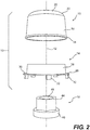
- Fig. 2 is a side view of the lightning strike protector 10 that is shown in Fig. 1 .
- Fig. 2 is an exploded view to facilitate an understanding of the various components of the present invention.
- Fig. 3 is a side view of the lightning strike protector 10, shown in an assembled condition.
- the cap 12 and the insert 14 are contemplated to engage one another via an interference fit. It is noted, however, that the cap 12 may be secured to the insert 14 via any suitable means.
- the cap 12 may be secured to the insert 14 via an adhesive.
- the cap 12 may be bonded to the insert via ultrasonic welding or friction welding.
- the cap 12 and the insert 14 may be provided with ridges that engage one another, thereby discouraging the cap 12 from dislodging from the insert 14.
- the cap 12 may threadedly engage the insert 14.
- cap 12 and the insert 14 may be integrally formed as a single piece component. As should be apparent, it is also contemplated that the cap 12 and insert 14 may be made from three or more components without departing from the scope of the present invention.
- the cap 12 and the insert 14 may be manufactured using any of a number of manufacturing techniques. It is contemplated, for example, that the cap 12 and insert 14 may be manufactured using a layer manufacturing process (i.e ., a three dimensional printing technique), a vacuum forming process, a punching process, a thermoforming process, and an injection molding process. It is also contemplated that the cap 12 and insert 14 may be machined from a block (or blocks) of material by traditional machining techniques including, but not limited to, water jet machining. As should be apparent, the cap 12 and insert 14 may be manufactured using any of a number of different methodologies without departing from the scope of the present invention.
- the gap 50 established between the ring 26 and the surface 34 by the castellations 32 is more clearly defined.
- the gap 50 permits the sealant 36 that is provided within the lightning strike protector 10 to flow around the nut 16 and fill the interior void defined by the cap 12 and the insert 14. While relatively large gaps 50 are illustrated in Fig. 3 and also in the remaining drawings, it is noted that the gaps 50 may have any size, as required or as desired, without departing from the scope of the present invention. Further details concerning this aspect of the invention are provided in connection with the discussion of Fig. 14 , below.
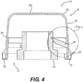
- Fig. 4 is a cross-sectional, side view of the lightning strike protector 10 illustrated in Fig. 3 .
- the cross-section is taken along the line 4 - 4 that is illustrated in Fig. 3 .
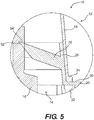
- Fig. 5 is a cross-sectional side view of a portion of the lightning strike protector 10 that is identified by the circle 5 in Fig. 4 .
- This enlarged view provides a more complete illustration of the interference engagement between one of the protrusions 38 and the nut 16.
- the finger-like protrusions 38 are contemplated to engage the surface of the nut 16 via an interference fit.
- the nut 16 may include a groove 52 into which a tip 54 of the protrusions 38 rests after the lightning strike protector 10 is fitted over the nut 16.
- other enhanced engagement features may be provided without departing from the scope of the present invention.
- Fig. 6 is a cross-sectional side view of a lightning strike protector 56 according to a second contemplated embodiment of the present invention.
- the lightning strike protector 56 is the same as the lightning strike protector 10 illustrated above in most respects.
- the lightning strike protector 56 includes one or more twist discouraging tabs 58 within the cap 12.
- the twist discouraging tabs 58 extend downwardly from the interior surface of the cap 12, at locations proximate to the central axis 42.
- the twist discouraging tabs 58 are provided to extend into the space above the nut 16 so that, when the sealant 36 cures, the twist discouraging tabs 58 will become encased in the cured resin 36.
- twist discouraging tabs 58 which are connected to the cap 12, will discourage the cap 12 from rotating with respect to the cured (i.e ., solidified) sealant 36. In this manner, the cap 12 is maintained in a fixed relationship to the cured sealant 36. While three twist discouraging tabs 58 are illustrated, a larger or a fewer number may be employed without departing from the scope of the present invention. In addition, while the twist discouraging tabs 58 are shown as extending to the top of the nut 16, this configuration is not required to practice the present invention. To the contrary, it is contemplated that the twist discouraging tabs 58 will not extend to a position less than 0.1 inches (2.54 mm) near to the nut 16. By maintaining a distance between the twist discouraging tabs 58 and the nut 16, the present invention eliminates a possible avenue for a spark to bridge the distance between the nut 16 and the twist discouraging tabs 58.
- Fig. 7 is a partial, cross-sectional side view of a third embodiment of the lightning strike protector 60 according to the present invention.
- This embodiment is intended to incorporate the same features as discussed in connection with the lightning strike protector 10.
- a plurality of stacked protrusions 62 extending inwardly from the wall 28 forming part of the insert 14. Additional protrusions 62 are contemplated to provide improved securement of the lightning strike protector 62 and the nut 16. As before, the protrusions 62 engage the top portion 46 of the nut.
- the shape of the protrusions 62 differs from the shape of the protrusions 38 that are discussed in connection with the lightning strike protector 10. As should be apparent to those skilled in the art, the exact shape of the protrusions 38, 62 is not critical to the construction and operation of the present invention. It is contemplated, however, that the protrusions 38, 62 will be shaped so as not to impede flow of the sealant 36 within the lightning strike protector 10.
- Fig. 8 is a partial, cross-sectional side view of a fourth embodiment of the lightning strike protector 64 according to the present invention. As before, this embodiment is contemplated to be similar to the lightning strike protector 10 discussed above. In this embodiment, however, a plurality of curved protrusions 66, 68 extend inwardly from the top end of the wall 28 to engage the nut 16.
- Fig. 9 is a partial, cross-sectional side view of a fifth embodiment of the lightning strike protector 70 according to the present invention.
- This embodiment also incorporates many of the features discussed in connection with the lightning strike protector 10.
- the protrusions 38 are replaced by a protrusion 72, which may be formed as a crimped section of the wall 28.
- the wall 18 of the cap 12 also may be crimped to establish a further connection between the cap 12 and the insert 14.
- only the cap 12 may be crimped to establish a connection between the cap 12 and the insert 14.
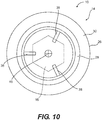
- Fig. 10 is a top view of the lightning strike protector 10, illustrating the relative positioning of the protrusions 38 with respect to one another.
- the cap 12 is not included in this view but has been removed. It is noted that the three protrusions 38 are equidistantly spaced from one another. As a result, the protrusions 38 are approximately 120° from one another. It is contemplated that, however, that the protrusions 38 need not be evenly spaced from one another to practice the present invention.
- Fig. 11 is a top view of a sixth embodiment of the lightning strike protector 74 according to the present invention. As with Fig. 10 , this illustration does not include the cap 12. In this embodiment, the lightning strike protector includes four (4) protrusions 38, disposed approximately 90° from one another.
- Fig. 12 is a top view of a seventh embodiment of the lightning strike protector 76 according to the present invention.
- This embodiment includes six protrusions 78 that are triangularly shaped.
- This embodiment illustrates that the shape of the protrusions 78 is not critical to the construction and operation of the present invention. In other words, the protrusions 78 may have any of a number of different shapes while remaining within the scope of the present invention.
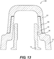
- Fig. 13 is a graphical illustration of a cross-sectional side view of an eighth embodiment of the lightning strike protector 80 according to the present invention.
- the cap 82 includes a recess 84 that accommodates the wall 28 therein.
- the castellations 32 are illustrated as being taller than the castellations 32 shown in the embodiment illustrated in Fig. 1 .
- the protrusions 38 and the castellations 32 may be aligned radially with one another. Alternatively, the protrusions 38 and the castellations 32 may not be aligned radially. Still further, some of the protrusions 38 and castellations 32 may be aligned, while others are not. It is contemplated that the radial alignment or misalignment of the protrusions and castellations will depend upon a number of variables including, but not limited to, the flow of the sealant 36 within the cap 12 and around the protrusions 38. The locations shapes, and number of the protrusions 38 and the castellations 32 is contemplated to affect the flow of the sealant 36 within the cap 12, which may have a bearing on the placement of the protrusion 38 and castellations 32.
- Fig. 14 is a cross-sectional side view of the lightning strike protector 10 that is shown in Fig. 1 .
- the lightning strike protector 10 is illustrated in a position separate and apart from the nut 16.
- the cap 12 is shown as having been partially filled with the sealant 36.
- Fig. 14 will now be used to discuss one way in which the lightning strike protector 10 is fitted over the nut 16. This illustration also assists with a discussion of one or more aspects of the present invention.
- the composition of the sealant 36 that is used as a protective coating on bolts in the fuel tanks on aircraft is not critical to the construction or operation of the present invention.
- the sealant 36 is understood to exhibit one or more of the following properties.
- First, the sealant is understood to begin in a fluid (or liquid) state where the sealant has the consistency of a silicone caulk, for example. The sealant cures (or hardens) to create a solid mass.
- the sealant possesses a sufficiently high dielectric property to resist transitioning into a plasma when exposed to the energy from a lightning strike on the aircraft.
- the sealant is contemplated to remain in the aircraft's fuel tank for an extended period of time (i.e ., the lifetime of the fuel tank). As such, the sealant resists degradation from the fuel and also resists the formation of cracks and other defects over time.
- cap 12 and the insert 14 concerns their ability to resist degradation in response to environmental conditions. For example, it may be prudent to add an ultraviolet (“UV”) stabilizer (or a UV coating) to the cap 12 and/or the insert 14 to protect against UV degradation. Still further, it may be advisable to add other stabilizers (and/or coatings) to increase the longevity and stability of the cap 12 and/or the insert 14 over an extended period of time, possibly for the operational lifetime of the aircraft.
- UV ultraviolet
- other stabilizers and/or coatings
- the protector 10 of the present invention is discussed in connection with lighting strike protection and electricity protection, the present invention should not be understood to be limited thereto.
- the protector 10 of the present invention also may function to provide protection against weathering, such as from moisture (i.e ., prevent oxidation and rusting of the components covered thereby).
- the protector 10 may be employed in a position where the nut 16 and bolt (not shown) are to be insulated from contact with fuel and other liquids. As such, it is contemplated that the protector 10 may be employed as a liquid barrier in addition to providing electrical insulation.
- the sealant 36 typically is applied to nuts 16 and bolts so that the sealant has a thickness of 0.1 inches (2.54 mm) or more. This thickness is understood to be sufficient to provide lightning strike protection in the fuel tanks on board an aircraft.
- the thickness of 0.1 inches (2.54 mm) is considered to be a minimum thickness for the sealant 36 at locations where the electrical spark may leak from the nut 16 or associated bolt. Spark leakage locations include, but are not limited to, the top of the nut 16, the connection seam between the nut 16 and associated bolt, and the contact point between the nut 16 and the surface 34. Where a washer (not shown) is disposed between the nut 16 and the surface 34, additional spark leakage locations include the contact point between the washer and the surface 34 and the contact point between the washer and the nut 16.
- the sealant 36 is contemplated to be provided with a thickness of at least 0.1 inches (2.54 mm) at each of these locations, when present.
- the thickness of the sealant 36 is contemplated to be at least 0.1 inches (2.54 mm) at the locations where spark leakage is contemplated to occur. As noted, this includes, but is not limited to, the contact point A between the nut 16 ( i.e ., the cylindrical lower portion 46) and the surface 34. This also includes the contact point B between the nut 16 ( i.e ., the hexagonal upper portion 44) and the bolt (not shown) that is contemplated to be disposed in the central bore 48.
- Fig. 7 illustrates radii r that are intended to illustrate the zone of minimum thickness for the sealant 36 around the contact points A, B. It is contemplated that, the thickness of the sealant 36 adjacent to a location where spark leakage is possible will not be less than 0.1 inches (2.54 mm).
- the 0.1 inch (2.54 mm) minimum is contemplated for the present invention, it is noted that sealants with a higher capacity to insulate against spark leakage may be employed. If so, the radius r around the contact points A, B (etc.) may be less than 0.1 inches (2.54 mm). In other words, a smaller radius r is contemplated to fall within the scope of the present invention.
- the radius r (which is also referred to as the minimum sealant thickness) is contemplated to fall within a range of 0.1 inches (2.54 mm) ⁇ 50 %.
- the minimum sealant thickness may be 0.1 inches (2.54 mm) ⁇ 40 %.
- the minimum sealant thickness may be 0.1 inches (2.54 mm) ⁇ 30 % without departing from the present invention.
- Minimum sealant thicknesses of 0.1 inches (2.54 mm) ⁇ 20 %, ⁇ 10 %, and ⁇ 5 % also are contemplated for the present invention.
- one aspect of the present invention concerns the distance of the protrusions 38 from the surface 34 (or the bottoms of the castellations 32. It is contemplated that the minimum distance from the protrusions 38 to the surface 34 is at least 0.1 inches (2.54 mm) to assure that the minimum thickness of the sealant 36 is deposited at the bottom of the nut 16, adjacent to the surface 34. Of course, as indicated above, a larger distance may be employed without departing from the scope of the present invention.
- the dimensions and structure of the protector 10 of the present invention concern the ability to manufacture the various components that comprise the protector 10. Since it is contemplated that the components of the protector 10 may be made from a material that is injection-molded (i.e ., plastics), the dimensions and shapes of the parts of the protector 10 necessarily will be determined, at least in part, by geometries that are readily formed and released from a mold. As should be apparent, however, these variables are not considered to be limiting of the scope of the present invention.
- the lighting strike protector 10 of the present invention is contemplated first to be filled with a predetermined quantity of the sealant, as shown in Fig. 14 .
- the lightning strike protector 10 is then positioned over the exposed nut 16, as indicated by the arrow 86.
- the protrusions 38 grip onto the nut to hold the lightning strike protector 10 in the correct orientation.
- the protrusions 38 also ensure that the spacing around the nut 16 is substantially the same around the entire periphery of the nut 16.
- the sealant 36 flows from the initial position proximate to the top end 20 of the cap 12 and proceeds to fill the remaining volume of the interior of the lightning strike protector 10 not occupied by the nut 16. In this manner, the sealant 36 fills the spatial volume defined between the lightning strike protector 10 and the nut 16.
- the sealant 36 occupies the entire volume under the cap 12, the space in the gap 50, and the space beneath the ring 26 of the insert 14.
- the sealant 36 is contemplated to fill the gap 50 up to the interior wall defined by the castellations 32 under the ring 26. This assures that a proper amount of sealant 36 is employed. It is also contemplated that an excess of sealant 36 may be employed so that the sealant 36 occupies the gaps 50 between the castellations 32 without departing from the scope of the present invention.
- the cap 12 may include a marking on the interior surface that acts as a fill line. If the cap 12 is filled with sealant 36 to the line, it is understood that the sealant will occupy the entirety of the volume between the lightning strike protector 10 and the nut 16.
- the lightning strike protector 10 may be used for nuts 16 with different sizes and shapes. If so, a suitable fill line may be provided for each different shape or size of nut 16.
- the present invention may include several variants for the insert 14 to accommodate the different configurations of nuts 16.
- a first insert 14 may be used for a first type of bolt 16 and a second insert 14 may be used for a second type of bolt 16.
- the cap 12 may be the same for both nuts 16.
- the present invention offers an economy of manufacture: one cap 12 may be made for a large variety of nuts 16 and a plurality of different inserts 14 may be manufactured for the different types of nuts expected to be covered by the lightning strike protector 10 of the present invention.
- the protrusions 38 hold the lightning strike protector 10 in place until the sealant 36 cures. Once cured, the sealant 36 and the protrusions 38 cooperate to discourage removal of the lightning strike protector 10 from the nut 16. Specifically, the cured sealant 36 reinforces the positions of the protrusions 38 and holds the protrusions 38 against the nut 16. In this manner, the sealant 36 helps the cap 12 and insert 14 remain attached to the bolt 16.
- the protrusions 38 also are anticipated to hold the cap 12 in place, should a failure develop between the sealant 36 and the cap 12. For example, during use, if an air gap should develop between the walls of the cap 12 and the sealant 36, the protrusions 38, which become locked in place when the sealant 36 cures, are contemplated to hold the lightning strike protector 10 in the proper orientation. As a result, the protrusions 38 act as a safety feature for the lighting strike protector 10.
- the cap 12 may be filled with an amount of sealant 36 in excess of the amount needed to fill the void established between the lightning strike protector 10 and the nut 16. In this instance, the sealant 36 is permitted to ooze out of the gap 50. The installer may then remove the excess sealant 36 after installation but before the sealant 36 cures.
- the gap 50 provides a visual indicator of a faulty installation.
- the gap 50 also provides a convenient way to remove excess sealant 36 for those installations where excess sealant 36 had been intentionally provided.
- the cap 12 may be made from a transparent or a translucent material. If so, a person may be able to visually determine if any air bubbles have developed in the sealant 36 inside of the lightning strike protector 10.
- the cap 12 may include an abraded interior surface so that the sealant 36, when cured, will adhere more strongly to the interior of the cap 12, thereby enhancing the efficacy of the seal for an extended period of time.
- the interior of the cap may be provided with a plurality of hair-like cilia, bumps, castellations, hollows, etc., on its interior surface to facilitate bonding between the sealant 36 and the cap 12.
- the interior of the cap 12 may be machined, plasma treated, exposed to a corona discharge, or mechanically abraded to establish an interior surface that has a greater affinity for adhesion to the sealant 36.
- the caps 12 may be color coded.
- the color coding may indicate that the lightning strike protector 10 meets specific safety requirements.
- the color coding might also indicate other aspects such as the thickness of the sealant 36 under the cap 12, the type of nut 16 under the cap, etc.
- Identifying indicia may be molded into the surface of the cap 12, as required or as desired.
- the shape of the cap 12 and insert 14 are not considered to be critical to the operation of the lightning strike protector 10 of the present invention. However, to minimize the amount of sealant employed, it may be desirable to fashion the cap 12 and insert 14 so that the components compliment the shape of the bolt 16.
- the protrusions 38 will assist with protection of the nut 16 in the event of a lightning strike. Specifically, the protrusions 38 are contemplated to provide an extra gripping force to prevent the lightning strike protector 10 from blowing off of the nut 16 in the event of a lightning strike.
- the exterior surface of the cap 12 may be provided with a roughened, exterior surface to facilitate installation of the lightning strike protector 10.
- the cap 12 may be provided with striations akin to the striations found on the cap of a toothpaste tube. If provided, the striations are expected to assist the installer to grip the lightning strike protector 10 during installation, thereby assuring a proper installation and fit.
- the striations (or similar external features) are contemplated to assist, should the placement of the lightning strike protector 10 be made via an automated process and/or device.
- the cap 12 and insert may be made from a non-metallic material.
- Non-metallic materials include, but are not limited to, ceramics, plastics, thermoset plastics, polymers, etc.
- the non-metallic materials may include non-metallic fillers, such as glass fibers, for example.
- the material selected for the cap 12 and insert 14 will have dielectric properties similar to the sealant, this is not required for practice of the present invention.
- the cap 12 and insert 14 may have a dielectric constant that is less than or greater than the sealant 36 without departing from the scope of the present invention.
- cap 12 and insert 14 may be manufactured by any of a number of different techniques.
- Contemplated manufacturing methods include injection molding, thermoforming, vacuum forming, and additive layer manufacturing, among others.
- the sealant 36 will be filled into the cap 12 immediately prior to installation, it is contemplated that the lightning strike protector 10 may be filled with sealant 10, frozen, and stored until required for use. In this embodiment, it is contemplated that an automated manufacturing method may be used to assure that each lightning strike protector 10 includes precisely the required amount of sealant 36, thereby avoiding waste (among other things).
- the sealant 36 may be polysulfide with or without additional ingredients and/or components.
- Fig. 15 is a top view of a further contemplated embodiment of the present invention.
- the insert 14 includes two protrusions 88.
- Each protrusion includes arms 90 that extend outwardly therefrom.
- the protrusions 88 and arms 90 engage the nut 16 and discourage rotation with respect thereto.
- the arms 90 on the protrusions 88 are separated from one another by gaps 92.
- This embodiment contemplates that the lightning strike protector 10 need have only two protrusions 88 associated with the insert 14.
- the configuration of the protrusions and the arms 90 is but one possible configuration when two protrusions 88 are employed.
- Fig. 16 is a top view of a further embodiment of the lightning strike protector 10 of the present invention.
- the insert 14 includes only one protrusion 94.
- the protrusion 94 include a ring 96 that encircles the nut 16, thereby providing engagement between the nut 16 and the insert 14.
- This embodiment illustrates that the present invention need only include one protrusion 94 for its operation.
- the shape and size of the protrusion 94 and ring 96 is not critical to the present invention.
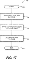
- Fig. 17 is a flow chart that illustrates a method 100 associated with the operation of the present invention.
- the method 100 begins at step 102.
- the method 100 proceeds to step 104 where the sealant 36 is introduced into the cap 12.
- step 104 the method 100 proceeds to step 106 where the cap 12 is positioned over the structure, such as the nut 16.
- the method then proceeds to step 108, where the sealant 36 is permitted to cure.
- the method ends at step 110.
- the cap 12 is understood as having been pre-filled with the sealant 36 before the cap 12 is affixed to the nut 16.
- the insert 14 may or may not be affixed to the nut 16 prior to attachment of the cap 12.
- step 104 follows step 106.
- the sealant 36 may be injected into the lightning strike protector 10 after the cap 12 and insert 14 are placed on the nut 16.
Landscapes
- Engineering & Computer Science (AREA)
- Aviation & Aerospace Engineering (AREA)
- General Engineering & Computer Science (AREA)
- Mechanical Engineering (AREA)
- Gasket Seals (AREA)
- Pressure Vessels And Lids Thereof (AREA)
Description
- This patent application claims priority from a first-filed United States Provisional Patent Application,
US 61/758,477 - The present invention concerns a device that is applied to a nut, bolt, or other protruding structure to insulate the structure. In particular, the present invention concerns the design of a structure that establishes an electrical barrier between the protruding structure and its surrounding environment. More specifically, the present invention provides a device that insulates a nut, bolt, or other protruding structure from the surrounding environment in the event that there is a proximate lightning strike (i.e., Zone 2 protection).
- It is known to provide protection for nuts and bolts within the interior of an aircraft's fuel tank from lightning strikes on the aircraft.
- As should be apparent to those skilled in the art, if an aircraft is struck by lightning, it is possible that a portion of the energy from the lightning may travel to a nut or bolt within the fuel tank on the aircraft. While remote, the energy from the lightning might initiate a spark that could ignite the fuel in the fuel tank.
- To prevent the occurrence of such an event, however remote the occurrence might be, it is customary for aircraft manufacturers to cover any protruding nuts and/or bolts with a sealant that isolates the nut or bolt from the environment within the fuel tank.
- One known method of sealing protruding structures is to coat the structures with a suitable sealant.
- Another method involves creating a cup from the sealant by allowing a thin layer of the sealant to cure. The remaining volume of the cup is then filled with additional sealant before being applied to the protruding structure in the fuel tank of the aircraft.
-
U.S. Patent No. 4,382,049 (hereinafter "the '049 Patent") describes a lightning spark isolation barrier that includes afastener 10 that is attached to asurface 12 viarivets 20. (The '049 Patent at col. 3, lines 1-2.) Thefastener 10 is located on the inner surface of an exterior skin of an aircraft in a critical fuel vapor area. (The '049 Patent at col. 3, lines 2-4.) Thefastener 10 is partially surrounded by acap 22 that is first filled with adielectric isolation material 24 in an uncured, viscous, or plastic form. (The '049 Patent at col. 3, lines 5-14.) Thecap 22 is made of plastic. (The '049 Patent at col. 3, lines 14-16.) -
U.S. Patent No. 4,905,931 (hereinafter "the '931 Patent") describes an arc suppression apparatus that is positioned around a fastener. Thefastener 10 attaches twocomposite members plastic cap 50 that is affixed to thecomposite member 22 at the surface 19 and is placed over the end of the fastener to enclose a volume of air gases 41 in thevoid 40. (The '931 Patent at col. 3, lines 15-20.) Apolysulfide rubber sealant 50 is provided outside of and around thecap 50 to ensure that an airtight seal around thevoid 40 exists at all times during the lifetime of the aircraft. (The '931 Patent at col. 3, lines 20-24.) -
U.S. Patent Application Publication No. 2012/0074257 (hereinafter "the '257 Application") describes a lightning-resistant fastener, cap, and method of mounting the lightning-resistant fastener. The '257 Application describes that acollar 26 is screwed onto a fastenermain body 25. (The '257 Application at paragraph [0040].) Thecollar 26 andscrew 25 are encased beneath acap 30 made from an insulating resin. (The '257 Application at paragraph [0046].) Thecap 30 is filled with asealant 34. (The '257 Application at paragraph [0052].) Thecap 30 may be pre-filled with thesealant 34 in an uncured state. (The '257 Application at paragraph [0053].) - While these methods are effective, there remains a desire for a simple, cost effective lightning strike protector.
- A further protective device is known from
WO 97/29289 - The present invention addresses one or more of the deficiencies noted with respect to the prior art.
- In particular, the present invention, provides an electrical protector with a central axis that includes a cap defining a top and a downwardly extending cap wall adapted for receiving a sealant, an insert defining a ring and an upwardly extending insert wall, a plurality of castellations for maintaining a gap between the ring and a surface on which the electrical protector sits, and at least one protrusion extending inwardly from an interior surface of the insert wall toward the central axis. The cap wall connects to the insert wall. The at least one protrusion is adapted to engage a structure, thereby securing the lightning strike protector onto the structure.
- According to one aspect of the present invention, the cap wall is frusto-conically shaped.
- According to another aspect of the present invention, the insert wall is frusto-conically shaped.
- In one embodiment of the present invention, the sealant is polysulfide.
- It is contemplated that the cap wall and the insert wall may engage one another by an interference fit.
- It is contemplated that the structure is at least one of a nut and a bolt. In addition, the structure may be located inside of a fuel tank of an aircraft.
- The plurality of castellations may extend downwardly from the ring. In an alternative construction, the castellations may extend downwardly, through openings in the ring.
- In another embodiment, it is contemplated that the insert will include multiple protrusions. If so, the protrusions may be substantially evenly distributed around the interior surface of the insert wall.
- Similarly, it is contemplated that the castellations may be substantially evenly distributed around the ring or the cap.
- It is contemplated that the cap and the insert may integrally form a single structure. Alternatively, the cap and the insert may be connected to one another via an adhesive.
- In one embodiment, it is contemplated that the cap and the insert are made from a ceramic, a plastic, a thermoset plastic, or a polymer. It is also contemplated that the cap and insert may include glass fibers.
- In one embodiment, the cap, the insert, and the sealant may have substantially equal dielectric properties. In alternative embodiments, the cap, the insert, and the sealant may have unequal dielectric properties.
- It is contemplated that the electrical protector may include one or more twist discouraging tabs extending into the cap from a location proximate to a center point of the cap.
- In another embodiment, the protrusion may be shaped as a finger-like element that extends inwardly from the insert wall. In other embodiments, the protrusion may be a triangularly-shaped element that extends inwardly from the insert wall. Separately, the protrusion may be a folded portion of the insert wall.
- It is contemplated that the electrical protector of the present invention may protect against lightning strikes.
- In one contemplated embodiment, three or more protrusions may extend inwardly from the insert wall.
- There is disclosed a method for positioning an electrical protector over a structure to be protected. The electrical protector has a central axis and comprises a cap defining a top and a downwardly extending cap wall adapted for receiving a sealant. The electrical protector also includes an insert defining a ring and an upwardly extending insert wall and one or more protrusions extending inwardly from an interior surface of the insert wall toward the central axis. The cap wall connects to the insert wall. The protrusion is adapted to engage a structure, thereby securing the electrical protector onto the structure. The method includes the steps of introducing the sealant into the cap, affixing the cap and insert to the structure with the at least one protrusion in contact with the structure, and allowing the sealant to cure, thereby locking the at least one protrusion against the structure.
- Still other aspects of the present invention will be made apparent from the discussion that follows.
- The present invention will now be described in connection with the drawings appended hereto, in which:
-
Fig. 1 is an exploded, perspective illustration of a first embodiment of the lightning strike protector according to the present invention; -
Fig. 2 is an exploded, side view of the embodiment of the lightning strike protector illustrated inFig. 1 ; -
Fig. 3 is a side view of the lighting strike protector shown inFig. 1 , with the components depicted in an assembled condition; -
Fig. 4 is a cross-sectional side view of the lightning strike protector illustrated inFig. 3 ; -
Fig. 5 is an enlarged detail of selected interior features of the lightning strike protector illustrated inFig. 4 ; -
Fig. 6 is a cross-sectional side view of a second embodiment of a lightning strike protector according to the present invention; -
Fig. 7 is an enlarged, cross-sectional side view of a third embodiment of a lightning strike protector according to the present invention; -
Fig. 8 is an enlarged, cross-sectional side view of a fourth embodiment of a lightning strike protector according to the present invention; -
Fig. 9 is an enlarged, cross-sectional side view of a fifth embodiment of a lightning strike protector according to the present invention; -
Fig. 10 is a top view of the insert portion of the lightning strike protector illustrated inFig. 1 ; -
Fig. 11 is a top view of a sixth embodiment of a lightning strike protector according to the present invention, specifically the insert portion thereof; -
Fig. 12 is a top view of a seventh embodiment of a lightning strike protector according to the present invention, specifically the insert portion thereof; -
Fig. 13 is a cross-sectional, side view of an eighth embodiment of a lightning strike protector according to the present invention; -
Fig. 14 is a cross-sectional side view of the first embodiment of the lightning strike protector of the present invention, illustrating a contemplated method of use thereof; -
Fig. 15 is a top view of an eighth embodiment of a lightning strike protector according to the present invention, specifically the insert portion thereof; -
Fig. 16 is a top view of a ninth embodiment of a lightning strike protector according to the present invention, specifically the insert portion thereof; and -
Fig. 17 is a graphical depiction of one contemplated method employable with the lightning strike protector of the present invention. - The present invention will now be described in connection with one or more embodiments. The discussion of any one particular embodiment or associated feature is not intended to be limiting of the present invention. To the contrary, the discussion of particular embodiments and features is intended to illustrate the breadth and scope of the present invention. There are numerous variations and equivalents that will be made apparent from the discussion that follows. Those variations and equivalents are intended to be encompassed by the scope of the present invention as if described herein.
- With respect to various features that are discussed in connection with specific embodiments, it is noted that the features are not intended to be exclusive of one another. To the contrary, as should be apparent to those skilled in the art, several of the features may be combinable in arrangements that differ from the specific embodiments described below. Those combinations are contemplated to fall within the scope of the present invention.
- It is noted that the present invention is described in connection with one or more embodiments of a
lightning strike protector 10. With respect to lightning strike protection, it is noted that the present invention is intended for Zone 2 protection. As should be apparent to those skilled in the art, Zone 2 protection refers to a device that is not contemplated to be subject to a direct lightning strike. - While the present invention is discussed in connection with lighting strike protection, the present invention should not be understood to be limited thereto. It is contemplated that the
protector 10 of the present invention may be employed in other, suitable environments. For example, it is contemplated that theprotector 10 may be incorporated into components associated with the generation and transmission of electricity. For example, the protector may be employed within a high voltage transformer or the like. -
Fig. 1 is a perspective illustration of a first contemplated embodiment of thelightning strike protector 10 according to the present invention. Thelightning strike protector 10 includes acap 12 and aninsert 14. Thecap 12 and insert 14 are contemplated to fit over abolt 16 that is interior to the fuel tank of an aircraft. - While the present invention has been designed for installation in the fuel tank(s) of an aircraft, the present invention should not be understood to be limited to use in aircraft. To the contrary, it is contemplated that the
lightning strike protector 10 may be employed in the fuel tanks of other vehicles including, but not limited to, locomotives, boats, ships, cars, etc. - In addition, while the present invention has been designed for installation in the fuel tanks for an aircraft, it is contemplated that the
lightning strike protector 10 may be used outside of the context of a fuel tank without departing from the scope of the present invention. - In various ones of the figures that are discussed herein, a
nut 16 also in shown. As a general definition for purposes of the instant discussion, thenut 16 may be any structure that protrudes into the interior of the fuel tank for the aircraft. While thelightning protector 10 of the present invention is intended to cover thenut 16, thenut 16 is not considered to be a part of the present invention. Moreover, as should be apparent, the present invention should not be understood to be limited to lightning strike protection only for nuts 16. - In addition, the
nut 16 is illustrated as a hexagonal nut. As should be apparent, this is merely illustrative of one possible shape and configuration of thenut 16. Thelightning strike protector 10 may be used withnuts 16 having different shapes without departing from the scope of the present invention. - Referring to
Fig. 1 , thecap 12 is contemplated to be an inverted, cup-shaped structure. As such, thecap 12 is contemplated to include a cylindrically-shapedwall 18 and a sealed,top end 20. In the illustrated embodiment, the cylindrically-shapedwall 18 connects to thetop end 20 via arounded transition region 22. Therounded transition region 22 is contemplated to provide a convenient transition between thewall 18 and the top 20 of thecap 12. - In the illustrated embodiment, the bottom edge of the
wall 18 includes alip 24, which is contemplated to provide thewall 18 with increased strength and rigidity. It is noted, however, that thelip 24 is not required to practice the present invention. To the contrary, thelip 24 may be omitted in its entirety without departing from the scope of the present invention. - It is contemplated that the
cap 12 will be made from a plastic or thermoplastic material. While any particular material may be used, it is contemplated that materials that are easy to manufacture using injection molding techniques or thermoforming techniques encompass preferred materials. As should be apparent, however, thelightning strike protector 10 of the present invention is not intended to be limited to any particular material or construction technique. - With continued reference to
Fig. 1 , the other half of thelightning strike protector 10 is theinsert 14. Theinsert 14 is essentially aring 26 with an upwardly-extendingwall 28. Thering 14 also is contemplated to be made from a plastic or thermoplastic material. - It is contemplated that the
cup 12 and thering 14 may be made from the same material. In an alternative contemplated embodiment, thecup 12 and thering 14 may be made from different materials without departing from the scope of the present invention. - The
ring 26 is essentially a flat, circular structure that presents, enter alia, aseating surface 30 for thelip 24 on thecap 12. Thewall 28 is frusto-conically shaped to mate with the interior surface of thecap 12. Thewalls 18 of the cap also are frusto-conically shaped. Thewalls cap 12 andinsert 14. Thewalls cap 12 and theinsert 14. - With respect to the
insert 14, it is also noted that thesurface 30 of thering 26 presents a suitable surface for connecting theinsert 14 to thecap 12 via any suitable attachment. For example, thecap 12 may be ultrasonically welded to thering 26. Alternatively, thecap 12 may be connected to thering 26 via an adhesive. Still further, friction welding may be employed. Other connection means also are contemplated to fall within the scope of the present invention. As should be apparent, the complimentary construction of thewalls cap 12 and theinsert 14. As also should be apparent, thewalls - A plurality of
castellations 32 extend from below thering 26. Thecastellations 32 are provided so that thering 26 does not come into contact with thesurface 34 on which thenut 16 sits. As discussed in greater detail below, thecastellations 32 establish apurposeful gap 50 between thering 26 and thesurface 34. This permits sealant 36 (seeFig. 14 ) to flow within the interior of thecap 12 and insert 14 and fill the spatial volume defined therein, thereby facilitating adequate coverage of thenut 16 with thesealant 36. - In an alternative contemplated embodiment, the
castellations 32 may be formed as a part of thecap 12 and extend through holes in theinsert 14. As should be apparent, thecastellations 32 need not be part of theinsert 14 in order to practice the present invention. - It is noted that the first embodiment of the
lightning strike protector 10 includes fivecastellations 32. As should be understood, a larger or fewer number ofcastellations 32 may be employed without departing from the scope of the present invention. Moreover, thecastellations 32 may have any suitable shape, size or thickness without departing from the scope of the present invention. For example, without limitation of the present invention, a minimum of twocastellations 32 may be provided that extend around nearly the entire periphery of thering 26. - A plurality of
protrusions 38 extend toward the center of theinsert 14 from an interior surface of thewall 28. Theprotrusions 38 are contemplated to be flexible. Theprotrusions 38 extend a sufficient distance toward thecenter 40 of theinsert 14 so that theprotrusions 38 engage an exterior surface of thenut 16, thereby securing thelightning strike protector 10 in a fixed orientation with respect to thenut 16. For reference, acentral axis 42 of thelightning strike protector 10 also is illustrated. - As should be apparent, the
protrusions 38 also are provided to lock thelightning strike protector 10 in relation to thenut 16. In addition, theprotrusions 38 also are contemplated to assist with locking thenut 16 so that thenut 16 does not become loose or dislodged during operation of the aircraft. - In one or more embodiments of the present invention, it is noted that the
lightning strike protector 10 is contemplated to include a minimum of threeprotrusions 38. When theprotrusions 38 are designed as finger-shaped or tab-shaped structures (among other shapes), three is considered to be the minimum number ofprotrusions 38 that are needed to center theinsert 14 and thecap 12 around thenut 16. As should be apparent, a larger number ofprotrusions 38 may be employed without departing from the scope of the present invention. Moreover, as discussed in connection withFigs. 15 and16 , one or two protrusions may be employed in instances where the protrusions include one or more fixation elements, such as arms and/or a ring. - The
nut 16 includes a hexagonalupper portion 44 and a cylindricallower portion 46. The shape of thenut 16, however, may be of any variety without departing from the scope of the present invention. The shape of thenut 16 presented in the figures is intended to be representative of one possible configuration that may be employed in the construction of an aircraft. Acentral bore 48 is shown for thenut 16. Thecentral bore 48 is contemplated to engage a bolt (not shown) via a suitable engagement, such as a threaded engagement. As should be apparent, any suitable engagement between the bolt and thenut 16 may be employed. The exact engagement is not a part of (nor critical to) the scope of the present invention. -
Fig. 2 is a side view of thelightning strike protector 10 that is shown inFig. 1 .Fig. 2 is an exploded view to facilitate an understanding of the various components of the present invention. -
Fig. 3 is a side view of thelightning strike protector 10, shown in an assembled condition. Thecap 12 and theinsert 14 are contemplated to engage one another via an interference fit. It is noted, however, that thecap 12 may be secured to theinsert 14 via any suitable means. For example, thecap 12 may be secured to theinsert 14 via an adhesive. Alternatively, thecap 12 may be bonded to the insert via ultrasonic welding or friction welding. Still further, thecap 12 and theinsert 14 may be provided with ridges that engage one another, thereby discouraging thecap 12 from dislodging from theinsert 14. In yet another contemplated embodiment, thecap 12 may threadedly engage theinsert 14. As should be apparent, there are numerous ways in which thecap 12 may engage theinsert 14. The present invention is not intended to be limited to any particular engagement between thecap 12 and theinsert 14. - In an alternative construction, it is contemplated that the
cap 12 and theinsert 14 may be integrally formed as a single piece component. As should be apparent, it is also contemplated that thecap 12 and insert 14 may be made from three or more components without departing from the scope of the present invention. - Concerning the manufacture of the
cap 12 and theinsert 14, it is contemplated that any of a number of manufacturing techniques may be employed therefor. It is contemplated, for example, that thecap 12 and insert 14 may be manufactured using a layer manufacturing process (i.e., a three dimensional printing technique), a vacuum forming process, a punching process, a thermoforming process, and an injection molding process. It is also contemplated that thecap 12 and insert 14 may be machined from a block (or blocks) of material by traditional machining techniques including, but not limited to, water jet machining. As should be apparent, thecap 12 and insert 14 may be manufactured using any of a number of different methodologies without departing from the scope of the present invention. - With continued reference to
Fig. 3 , thegap 50 established between thering 26 and thesurface 34 by thecastellations 32 is more clearly defined. As noted, thegap 50 permits thesealant 36 that is provided within thelightning strike protector 10 to flow around thenut 16 and fill the interior void defined by thecap 12 and theinsert 14. While relativelylarge gaps 50 are illustrated inFig. 3 and also in the remaining drawings, it is noted that thegaps 50 may have any size, as required or as desired, without departing from the scope of the present invention. Further details concerning this aspect of the invention are provided in connection with the discussion ofFig. 14 , below. -
Fig. 4 is a cross-sectional, side view of thelightning strike protector 10 illustrated inFig. 3 . The cross-section is taken along the line 4 - 4 that is illustrated inFig. 3 . -
Fig. 5 is a cross-sectional side view of a portion of thelightning strike protector 10 that is identified by the circle 5 inFig. 4 . This enlarged view provides a more complete illustration of the interference engagement between one of theprotrusions 38 and thenut 16. It is noted that the finger-like protrusions 38 are contemplated to engage the surface of thenut 16 via an interference fit. However, to provide enhanced securement between thenut 16 and theprotrusions 38, it is contemplated that thenut 16 may include agroove 52 into which atip 54 of theprotrusions 38 rests after thelightning strike protector 10 is fitted over thenut 16. As should be apparent to those skilled in the art, other enhanced engagement features may be provided without departing from the scope of the present invention. -
Fig. 6 is a cross-sectional side view of alightning strike protector 56 according to a second contemplated embodiment of the present invention. Thelightning strike protector 56 is the same as thelightning strike protector 10 illustrated above in most respects. Thelightning strike protector 56, however, includes one or moretwist discouraging tabs 58 within thecap 12. Specifically, thetwist discouraging tabs 58 extend downwardly from the interior surface of thecap 12, at locations proximate to thecentral axis 42. The twistdiscouraging tabs 58 are provided to extend into the space above thenut 16 so that, when thesealant 36 cures, thetwist discouraging tabs 58 will become encased in the curedresin 36. Once the sealant cures, thetwist discouraging tabs 58, which are connected to thecap 12, will discourage thecap 12 from rotating with respect to the cured (i.e., solidified)sealant 36. In this manner, thecap 12 is maintained in a fixed relationship to the curedsealant 36. While threetwist discouraging tabs 58 are illustrated, a larger or a fewer number may be employed without departing from the scope of the present invention. In addition, while thetwist discouraging tabs 58 are shown as extending to the top of thenut 16, this configuration is not required to practice the present invention. To the contrary, it is contemplated that thetwist discouraging tabs 58 will not extend to a position less than 0.1 inches (2.54 mm) near to thenut 16. By maintaining a distance between thetwist discouraging tabs 58 and thenut 16, the present invention eliminates a possible avenue for a spark to bridge the distance between thenut 16 and thetwist discouraging tabs 58. -
Fig. 7 is a partial, cross-sectional side view of a third embodiment of thelightning strike protector 60 according to the present invention. This embodiment is intended to incorporate the same features as discussed in connection with thelightning strike protector 10. In this embodiment, a plurality of stackedprotrusions 62 extending inwardly from thewall 28 forming part of theinsert 14.Additional protrusions 62 are contemplated to provide improved securement of thelightning strike protector 62 and thenut 16. As before, theprotrusions 62 engage thetop portion 46 of the nut. - It is noted that the shape of the
protrusions 62 differs from the shape of theprotrusions 38 that are discussed in connection with thelightning strike protector 10. As should be apparent to those skilled in the art, the exact shape of theprotrusions protrusions sealant 36 within thelightning strike protector 10. -
Fig. 8 is a partial, cross-sectional side view of a fourth embodiment of thelightning strike protector 64 according to the present invention. As before, this embodiment is contemplated to be similar to thelightning strike protector 10 discussed above. In this embodiment, however, a plurality ofcurved protrusions wall 28 to engage thenut 16. -
Fig. 9 is a partial, cross-sectional side view of a fifth embodiment of thelightning strike protector 70 according to the present invention. This embodiment also incorporates many of the features discussed in connection with thelightning strike protector 10. In this embodiment, however, theprotrusions 38 are replaced by aprotrusion 72, which may be formed as a crimped section of thewall 28. While not illustrated, it is contemplated that thewall 18 of thecap 12 also may be crimped to establish a further connection between thecap 12 and theinsert 14. In still another contemplated embodiment, only thecap 12 may be crimped to establish a connection between thecap 12 and theinsert 14. -
Fig. 10 is a top view of thelightning strike protector 10, illustrating the relative positioning of theprotrusions 38 with respect to one another. To facilitate an understanding of the invention, thecap 12 is not included in this view but has been removed. It is noted that the threeprotrusions 38 are equidistantly spaced from one another. As a result, theprotrusions 38 are approximately 120° from one another. It is contemplated that, however, that theprotrusions 38 need not be evenly spaced from one another to practice the present invention. -
Fig. 11 is a top view of a sixth embodiment of thelightning strike protector 74 according to the present invention. As withFig. 10 , this illustration does not include thecap 12. In this embodiment, the lightning strike protector includes four (4)protrusions 38, disposed approximately 90° from one another. -
Fig. 12 is a top view of a seventh embodiment of the lightning strike protector 76 according to the present invention. This embodiment includes sixprotrusions 78 that are triangularly shaped. This embodiment illustrates that the shape of theprotrusions 78 is not critical to the construction and operation of the present invention. In other words, theprotrusions 78 may have any of a number of different shapes while remaining within the scope of the present invention. -
Fig. 13 is a graphical illustration of a cross-sectional side view of an eighth embodiment of thelightning strike protector 80 according to the present invention. In this embodiment, thecap 82 includes arecess 84 that accommodates thewall 28 therein. In addition, thecastellations 32 are illustrated as being taller than thecastellations 32 shown in the embodiment illustrated inFig. 1 . - With respect to the various embodiments described herein, it is noted that the
protrusions 38 and thecastellations 32 may be aligned radially with one another. Alternatively, theprotrusions 38 and thecastellations 32 may not be aligned radially. Still further, some of theprotrusions 38 andcastellations 32 may be aligned, while others are not. It is contemplated that the radial alignment or misalignment of the protrusions and castellations will depend upon a number of variables including, but not limited to, the flow of thesealant 36 within thecap 12 and around theprotrusions 38. The locations shapes, and number of theprotrusions 38 and thecastellations 32 is contemplated to affect the flow of thesealant 36 within thecap 12, which may have a bearing on the placement of theprotrusion 38 andcastellations 32. -
Fig. 14 is a cross-sectional side view of thelightning strike protector 10 that is shown inFig. 1 . In this view, thelightning strike protector 10 is illustrated in a position separate and apart from thenut 16. In addition, thecap 12 is shown as having been partially filled with thesealant 36. -
Fig. 14 will now be used to discuss one way in which thelightning strike protector 10 is fitted over thenut 16. This illustration also assists with a discussion of one or more aspects of the present invention. - The composition of the
sealant 36 that is used as a protective coating on bolts in the fuel tanks on aircraft is not critical to the construction or operation of the present invention. As should be apparent to those skilled in the art, thesealant 36 is understood to exhibit one or more of the following properties. First, the sealant is understood to begin in a fluid (or liquid) state where the sealant has the consistency of a silicone caulk, for example. The sealant cures (or hardens) to create a solid mass. Second, the sealant possesses a sufficiently high dielectric property to resist transitioning into a plasma when exposed to the energy from a lightning strike on the aircraft. Third, the sealant is contemplated to remain in the aircraft's fuel tank for an extended period of time (i.e., the lifetime of the fuel tank). As such, the sealant resists degradation from the fuel and also resists the formation of cracks and other defects over time. - One further consideration for the
cap 12 and theinsert 14 concerns their ability to resist degradation in response to environmental conditions. For example, it may be prudent to add an ultraviolet ("UV") stabilizer (or a UV coating) to thecap 12 and/or theinsert 14 to protect against UV degradation. Still further, it may be advisable to add other stabilizers (and/or coatings) to increase the longevity and stability of thecap 12 and/or theinsert 14 over an extended period of time, possibly for the operational lifetime of the aircraft. - While the
protector 10 of the present invention is discussed in connection with lighting strike protection and electricity protection, the present invention should not be understood to be limited thereto. Theprotector 10 of the present invention also may function to provide protection against weathering, such as from moisture (i.e., prevent oxidation and rusting of the components covered thereby). Still further, theprotector 10 may be employed in a position where thenut 16 and bolt (not shown) are to be insulated from contact with fuel and other liquids. As such, it is contemplated that theprotector 10 may be employed as a liquid barrier in addition to providing electrical insulation. - Taking into account various aviation guidelines, the
sealant 36 typically is applied tonuts 16 and bolts so that the sealant has a thickness of 0.1 inches (2.54 mm) or more. This thickness is understood to be sufficient to provide lightning strike protection in the fuel tanks on board an aircraft. - The thickness of 0.1 inches (2.54 mm) is considered to be a minimum thickness for the
sealant 36 at locations where the electrical spark may leak from thenut 16 or associated bolt. Spark leakage locations include, but are not limited to, the top of thenut 16, the connection seam between thenut 16 and associated bolt, and the contact point between thenut 16 and thesurface 34. Where a washer (not shown) is disposed between thenut 16 and thesurface 34, additional spark leakage locations include the contact point between the washer and thesurface 34 and the contact point between the washer and thenut 16. Thesealant 36 is contemplated to be provided with a thickness of at least 0.1 inches (2.54 mm) at each of these locations, when present. - With renewed reference to
Fig. 7 , it is noted that the thickness of thesealant 36 is contemplated to be at least 0.1 inches (2.54 mm) at the locations where spark leakage is contemplated to occur. As noted, this includes, but is not limited to, the contact point A between the nut 16 (i.e., the cylindrical lower portion 46) and thesurface 34. This also includes the contact point B between the nut 16 (i.e., the hexagonal upper portion 44) and the bolt (not shown) that is contemplated to be disposed in thecentral bore 48.Fig. 7 illustrates radii r that are intended to illustrate the zone of minimum thickness for thesealant 36 around the contact points A, B. It is contemplated that, the thickness of thesealant 36 adjacent to a location where spark leakage is possible will not be less than 0.1 inches (2.54 mm). - While the 0.1 inch (2.54 mm) minimum is contemplated for the present invention, it is noted that sealants with a higher capacity to insulate against spark leakage may be employed. If so, the radius r around the contact points A, B (etc.) may be less than 0.1 inches (2.54 mm). In other words, a smaller radius r is contemplated to fall within the scope of the present invention.
- In this regard, at least for the present invention, the radius r (which is also referred to as the minimum sealant thickness) is contemplated to fall within a range of 0.1 inches (2.54 mm) ± 50 %. In an alternative embodiment, the minimum sealant thickness may be 0.1 inches (2.54 mm) ± 40 %. In still another embodiment, the minimum sealant thickness may be 0.1 inches (2.54 mm) ± 30 % without departing from the present invention. Minimum sealant thicknesses of 0.1 inches (2.54 mm) ± 20 %, ± 10 %, and ± 5 % also are contemplated for the present invention.
- Taking the minimum thickness of the
sealant 36 into account, one aspect of the present invention concerns the distance of theprotrusions 38 from the surface 34 (or the bottoms of thecastellations 32. It is contemplated that the minimum distance from theprotrusions 38 to thesurface 34 is at least 0.1 inches (2.54 mm) to assure that the minimum thickness of thesealant 36 is deposited at the bottom of thenut 16, adjacent to thesurface 34. Of course, as indicated above, a larger distance may be employed without departing from the scope of the present invention. - As also should be apparent to those skilled in the art, other considerations associated with the dimensions and structure of the
protector 10 of the present invention concern the ability to manufacture the various components that comprise theprotector 10. Since it is contemplated that the components of theprotector 10 may be made from a material that is injection-molded (i.e., plastics), the dimensions and shapes of the parts of theprotector 10 necessarily will be determined, at least in part, by geometries that are readily formed and released from a mold. As should be apparent, however, these variables are not considered to be limiting of the scope of the present invention. - Taking advantage of the flowable property of the
uncured sealant 36, thelighting strike protector 10 of the present invention is contemplated first to be filled with a predetermined quantity of the sealant, as shown inFig. 14 . Thelightning strike protector 10 is then positioned over the exposednut 16, as indicated by thearrow 86. - As the
lightning strike protector 10 is pressed onto thenut 16, theprotrusions 38 grip onto the nut to hold thelightning strike protector 10 in the correct orientation. Theprotrusions 38 also ensure that the spacing around thenut 16 is substantially the same around the entire periphery of thenut 16. - When the
lightning strike protector 10 is pressed onto the nut, thesealant 36 flows from the initial position proximate to thetop end 20 of thecap 12 and proceeds to fill the remaining volume of the interior of thelightning strike protector 10 not occupied by thenut 16. In this manner, thesealant 36 fills the spatial volume defined between thelightning strike protector 10 and thenut 16. - When filled properly, the
sealant 36 occupies the entire volume under thecap 12, the space in thegap 50, and the space beneath thering 26 of theinsert 14. In other words, thesealant 36 is contemplated to fill thegap 50 up to the interior wall defined by thecastellations 32 under thering 26. This assures that a proper amount ofsealant 36 is employed. It is also contemplated that an excess ofsealant 36 may be employed so that thesealant 36 occupies thegaps 50 between thecastellations 32 without departing from the scope of the present invention. - During installation, if any
sealant 36 oozes out from thegap 50, this suggests that the volume within thelightning strike protector 10 has not been properly filled with thesealant 36. In other words, if excessive sealant oozes out from thegap 50, this suggests the formation of an air bubble within thelightning strike protector 10. - In connection with the
cap 12, and with an eye to providing an appropriate amount of sealant, it is contemplated that thecap 12 may include a marking on the interior surface that acts as a fill line. If thecap 12 is filled withsealant 36 to the line, it is understood that the sealant will occupy the entirety of the volume between thelightning strike protector 10 and thenut 16. - In a further contemplated embodiment, it is contemplated that the
lightning strike protector 10 may be used fornuts 16 with different sizes and shapes. If so, a suitable fill line may be provided for each different shape or size ofnut 16. - With respect to the use of the
lightning strike protector 10 withnuts 16 of different sizes, the present invention may include several variants for theinsert 14 to accommodate the different configurations of nuts 16. In this embodiment, afirst insert 14 may be used for a first type ofbolt 16 and asecond insert 14 may be used for a second type ofbolt 16. Thecap 12 may be the same for both nuts 16. In this manner, the present invention offers an economy of manufacture: onecap 12 may be made for a large variety ofnuts 16 and a plurality ofdifferent inserts 14 may be manufactured for the different types of nuts expected to be covered by thelightning strike protector 10 of the present invention. - Once the
lightning strike protector 10 is placed onto thenut 16, theprotrusions 38 hold thelightning strike protector 10 in place until thesealant 36 cures. Once cured, thesealant 36 and theprotrusions 38 cooperate to discourage removal of thelightning strike protector 10 from thenut 16. Specifically, the curedsealant 36 reinforces the positions of theprotrusions 38 and holds theprotrusions 38 against thenut 16. In this manner, thesealant 36 helps thecap 12 and insert 14 remain attached to thebolt 16. - Separately, it is noted that the
protrusions 38 also are anticipated to hold thecap 12 in place, should a failure develop between thesealant 36 and thecap 12. For example, during use, if an air gap should develop between the walls of thecap 12 and thesealant 36, theprotrusions 38, which become locked in place when thesealant 36 cures, are contemplated to hold thelightning strike protector 10 in the proper orientation. As a result, theprotrusions 38 act as a safety feature for thelighting strike protector 10. - It is also contemplated that the
cap 12 may be filled with an amount ofsealant 36 in excess of the amount needed to fill the void established between thelightning strike protector 10 and thenut 16. In this instance, thesealant 36 is permitted to ooze out of thegap 50. The installer may then remove theexcess sealant 36 after installation but before thesealant 36 cures. - As noted above, when the
lightning strike protector 10 is not properly installed, it is likely that somesealant 36 will ooze out from under thecap 12 through thegap 50. As a result, thegap 50 provides a visual indicator of a faulty installation. Thegap 50 also provides a convenient way to removeexcess sealant 36 for those installations whereexcess sealant 36 had been intentionally provided. - As should be apparent to those skilled in the art, it is often necessary to seal
nuts 16 that hang downwardly from anoverhead surface 34. Since thesealant 36 is flowable until it cures, thelightning strike protector 10 holds thesealant 36 in its inverted position until thesealant 36 cures. - With respect to the
cap 12, it is contemplated in one embodiment, that thecap 12 may be made from a transparent or a translucent material. If so, a person may be able to visually determine if any air bubbles have developed in thesealant 36 inside of thelightning strike protector 10. - In another contemplated embodiment, it is contemplated that the
cap 12 may include an abraded interior surface so that thesealant 36, when cured, will adhere more strongly to the interior of thecap 12, thereby enhancing the efficacy of the seal for an extended period of time. Alternatively, it is contemplated that the interior of the cap may be provided with a plurality of hair-like cilia, bumps, castellations, hollows, etc., on its interior surface to facilitate bonding between thesealant 36 and thecap 12. Separately, it is contemplated that the interior of thecap 12 may be machined, plasma treated, exposed to a corona discharge, or mechanically abraded to establish an interior surface that has a greater affinity for adhesion to thesealant 36. - Another embodiment of the present invention contemplates that the
caps 12 may be color coded. In this embodiment, the color coding may indicate that thelightning strike protector 10 meets specific safety requirements. The color coding might also indicate other aspects such as the thickness of thesealant 36 under thecap 12, the type ofnut 16 under the cap, etc. - Identifying indicia (i.e., a part number) may be molded into the surface of the
cap 12, as required or as desired. - As noted above, the shape of the
cap 12 and insert 14 are not considered to be critical to the operation of thelightning strike protector 10 of the present invention. However, to minimize the amount of sealant employed, it may be desirable to fashion thecap 12 and insert 14 so that the components compliment the shape of thebolt 16. - It is contemplated that the
protrusions 38 will assist with protection of thenut 16 in the event of a lightning strike. Specifically, theprotrusions 38 are contemplated to provide an extra gripping force to prevent thelightning strike protector 10 from blowing off of thenut 16 in the event of a lightning strike. - In yet another contemplated embodiment, the exterior surface of the
cap 12 may be provided with a roughened, exterior surface to facilitate installation of thelightning strike protector 10. For example, thecap 12 may be provided with striations akin to the striations found on the cap of a toothpaste tube. If provided, the striations are expected to assist the installer to grip thelightning strike protector 10 during installation, thereby assuring a proper installation and fit. Separately, the striations (or similar external features) are contemplated to assist, should the placement of thelightning strike protector 10 be made via an automated process and/or device. - While not considered to be limiting of the present invention, it is contemplated that the
cap 12 and insert may be made from a non-metallic material. Non-metallic materials include, but are not limited to, ceramics, plastics, thermoset plastics, polymers, etc. The non-metallic materials may include non-metallic fillers, such as glass fibers, for example. While it is contemplated that the material selected for thecap 12 and insert 14 will have dielectric properties similar to the sealant, this is not required for practice of the present invention. Specifically, thecap 12 and insert 14 may have a dielectric constant that is less than or greater than thesealant 36 without departing from the scope of the present invention. - It is noted that the
cap 12 and insert 14 may be manufactured by any of a number of different techniques. Contemplated manufacturing methods include injection molding, thermoforming, vacuum forming, and additive layer manufacturing, among others. - While it is contemplated that the
sealant 36 will be filled into thecap 12 immediately prior to installation, it is contemplated that thelightning strike protector 10 may be filled withsealant 10, frozen, and stored until required for use. In this embodiment, it is contemplated that an automated manufacturing method may be used to assure that eachlightning strike protector 10 includes precisely the required amount ofsealant 36, thereby avoiding waste (among other things). - While not considered to be limiting of the present invention, the
sealant 36 may be polysulfide with or without additional ingredients and/or components. -
Fig. 15 is a top view of a further contemplated embodiment of the present invention. In this top view, theinsert 14 includes twoprotrusions 88. Each protrusion includesarms 90 that extend outwardly therefrom. As such, theprotrusions 88 andarms 90 engage thenut 16 and discourage rotation with respect thereto. As illustrated, thearms 90 on theprotrusions 88 are separated from one another bygaps 92. This embodiment contemplates that thelightning strike protector 10 need have only twoprotrusions 88 associated with theinsert 14. As should be apparent, the configuration of the protrusions and thearms 90 is but one possible configuration when twoprotrusions 88 are employed. -
Fig. 16 is a top view of a further embodiment of thelightning strike protector 10 of the present invention. Here, theinsert 14 includes only oneprotrusion 94. Theprotrusion 94 include aring 96 that encircles thenut 16, thereby providing engagement between thenut 16 and theinsert 14. This embodiment illustrates that the present invention need only include oneprotrusion 94 for its operation. As should be apparent, the shape and size of theprotrusion 94 andring 96 is not critical to the present invention. -
Fig. 17 is a flow chart that illustrates amethod 100 associated with the operation of the present invention. - The
method 100 begins atstep 102. Themethod 100 proceeds to step 104 where thesealant 36 is introduced into thecap 12. Fromstep 104, themethod 100 proceeds to step 106 where thecap 12 is positioned over the structure, such as thenut 16. The method then proceeds to step 108, where thesealant 36 is permitted to cure. The method ends atstep 110. - As should be apparent from the foregoing, when the steps 104-108 are performed in the order delineated in
Fig. 17 , thecap 12 is understood as having been pre-filled with thesealant 36 before thecap 12 is affixed to thenut 16. Theinsert 14 may or may not be affixed to thenut 16 prior to attachment of thecap 12. - It is also contemplated that the
cap 12 and theinsert 14 may be affixed to thenut 16 before the sealant is added. In this contemplated variation,step 104 followsstep 106. In this contemplated variant, thesealant 36 may be injected into thelightning strike protector 10 after thecap 12 and insert 14 are placed on thenut 16. - As noted above, the present invention has been described in connection with several embodiments and variations. The present invention is not intended to be limited to any one particular embodiment or to any one particular feature described herein. To the contrary, there are numerous variations and equivalents that those skilled in the art would appreciate in connection with the present invention. Those variations and equivalents are intended to be encompassed by the present invention.
Claims (15)
- An electrical protector (10) with a central axis, comprising:a cap defining a top (20) and a downwardly extending cap wall (18) adapted for receiving a sealant (36);an insert (14) defining a ring (26) and an upwardly extending insert wall (28);a plurality of castellations (32) for maintaining a gap between the ring (26) and a surface (34) on which the electrical protector sits; andat least one protrusion (38) extending inwardly from an interior surface of the insert wall (28) toward the central axis;wherein the cap wall (18) connects to the insert wall (28), andwherein the at least one protrusion (38) is adapted to engage a structure (16), thereby securing the electrical protector onto the structure (16).
- The electrical protector of claim 1, wherein the cap wall (18) is frusto-conically shaped.
- The electrical protector of claim 1, wherein the insert wall (28) is frusto-conically shaped.
- The electrical protector of claim 1, wherein the sealant (36) comprises polysulfide.
- The electrical protector of claim 1, wherein the cap wall (18) and the insert wall (28) engage one another by an interference fit.
- The electrical protector of claim 1, wherein the structure (16) is at least one of a nut and a bolt.
- The electrical protector of claim 6, wherein the structure is located inside of a fuel tank of an aircraft.
- The electrical protector of claim 1, wherein the plurality of castellations (32) extend downwardly from the ring (26) of the insert.
- The electrical protector of claim 1, wherein the plurality of castellations (32) extend from the cap, through openings in the ring.
- The electrical protector of claim 1, wherein the protrusions (38) comprise a plurality of protrusions.
- The electrical protector of claim 10, wherein the plurality of protrusions (38) are substantially evenly distributed around the interior surface of the insert wall (28).
- The electrical protector of claim 8, wherein the plurality of castellations (32) are substantially evenly distributed around the ring (26).
- The electrical protector of claim 1, wherein the at least one protrusion (38) comprises a finger-like element that extends inwardly from the insert wall (28).
- The electrical protector of claim 1, wherein the at least one protrusion (38) comprises a triangularly-shaped element that extends inwardly from the insert wall (28).
- The electrical protector of claim 1, wherein the at least one protrusion (38) comprises a folded portion of the insert wall.
Applications Claiming Priority (2)
| Application Number | Priority Date | Filing Date | Title |
|---|---|---|---|
| US201361758477P | 2013-01-30 | 2013-01-30 | |
| PCT/EP2014/051491 WO2014118117A1 (en) | 2013-01-30 | 2014-01-27 | Electrical protector |
Publications (2)
| Publication Number | Publication Date |
|---|---|
| EP2951106A1 EP2951106A1 (en) | 2015-12-09 |
| EP2951106B1 true EP2951106B1 (en) | 2017-04-05 |
Family
ID=48326638
Family Applications (1)
| Application Number | Title | Priority Date | Filing Date |
|---|---|---|---|
| EP14701398.1A Active EP2951106B1 (en) | 2013-01-30 | 2014-01-27 | Electrical protector |
Country Status (6)
| Country | Link |
|---|---|
| US (1) | US10040568B2 (en) |
| EP (1) | EP2951106B1 (en) |
| CN (1) | CN104981412B (en) |
| CA (1) | CA2898673C (en) |
| GB (1) | GB201305459D0 (en) |
| WO (1) | WO2014118117A1 (en) |
Families Citing this family (31)
| Publication number | Priority date | Publication date | Assignee | Title |
|---|---|---|---|---|
| KR101254138B1 (en) * | 2011-03-16 | 2013-04-15 | 진재호 | Bolt And Nut Protection Cap |
| EP2986529B1 (en) * | 2013-04-19 | 2017-08-02 | Airbus Operations Limited | Injectable cap |
| GB2535518A (en) * | 2015-02-20 | 2016-08-24 | Airbus Operations Ltd | Cap with injected sealant |
| US9939006B2 (en) * | 2015-10-14 | 2018-04-10 | The Boeing Company | Sealing system for fasteners |
| US9879711B2 (en) | 2016-06-16 | 2018-01-30 | Honda Motor Co., Ltd. | Wheel bolt cap |
| US10655667B2 (en) | 2017-09-28 | 2020-05-19 | The Boeing Company | Rapid installation thermoplastic EME protection cap |
| GB2568890A (en) | 2017-11-29 | 2019-06-05 | Airbus Operations Ltd | Spark containment cap |
| US10843642B2 (en) * | 2018-03-21 | 2020-11-24 | Camisasca Automotive Manufacturing, Inc. | License plate fastener head cap assembly |
| GB2572376A (en) * | 2018-03-28 | 2019-10-02 | Airbus Operations Ltd | Cap with sealant flow path |
| US11199215B2 (en) | 2018-04-06 | 2021-12-14 | Novaria Holdings, LLC | Nut clip |
| US10962043B2 (en) | 2018-04-24 | 2021-03-30 | The Boeing Company | Anchoring nut for an EME protection cap system |
| US10920818B2 (en) | 2018-04-27 | 2021-02-16 | The Boeing Company | Anchoring washer for an EME protection cap system |
| US10948004B2 (en) | 2018-07-26 | 2021-03-16 | The Boeing Company | Anchoring bolt head for an EME protection cap system |
| GB2576701C (en) * | 2018-08-15 | 2023-03-29 | Short Brothers Plc | Electrical isolator fitting |
| US11078947B2 (en) * | 2018-09-11 | 2021-08-03 | The Boeing Company | Combustion quenching fastener caps with holes |
| US11022164B2 (en) | 2018-09-11 | 2021-06-01 | The Boeing Company | Double shell fastener caps |
| EP3623649A1 (en) * | 2018-09-14 | 2020-03-18 | Ruspa Officine S.P.A. | Anti-unscrewing and covering system for heads of bolts used to fix a rim of the wheel of an industrial vehicle |
| US11248647B2 (en) | 2018-11-09 | 2022-02-15 | The Boeing Company | EME cap for preventing uncured sealant squeeze out |
| US10989244B2 (en) | 2018-11-20 | 2021-04-27 | The Boeing Company | EME protection cap system with push sealant extrusion mechanism |
| US10982704B2 (en) | 2019-01-03 | 2021-04-20 | The Boeing Company | EME protection cap system with screw sealant mechanism |
| EP3924167B1 (en) * | 2019-02-11 | 2024-07-24 | PPG Industries Ohio Inc. | 3d printing of seal caps |
| US11236777B2 (en) | 2019-05-06 | 2022-02-01 | The Boeing Company | Friction fit electromagnetic effect protection cap system |
| US11788573B2 (en) | 2019-05-23 | 2023-10-17 | The Boeing Company | Multi-component melt electromagnetic effect protection cap system |
| US20210071704A1 (en) * | 2019-09-11 | 2021-03-11 | Pf Waterworks Lp | Toilet Bolt Cap |
| DE102019135416A1 (en) * | 2019-12-20 | 2021-06-24 | Rheinmetall Landsysteme Gmbh | Screw head protection |
| GB2591116B (en) * | 2020-01-16 | 2023-12-27 | Woolstencroft David | Method of protecting a fixing |
| WO2021155039A1 (en) * | 2020-01-29 | 2021-08-05 | Novaria Holdings, LLC | One-piece nut cap |
| US11754111B2 (en) | 2020-03-16 | 2023-09-12 | The Boeing Company | Compression fit EME protection seal cap |
| US11519451B2 (en) * | 2020-04-11 | 2022-12-06 | Atlas Tube Connections, Llc | Nut restrainer, and methods of use |
| US12264699B2 (en) * | 2021-01-13 | 2025-04-01 | The Boeing Company | Attachment of ignition suppression or quenching device to a fastener stack |
| US12391399B1 (en) * | 2023-09-27 | 2025-08-19 | United States Of America As Represented By The Secretary Of The Air Force | Temporary back-shell cover for an aircraft fuel tank |
Family Cites Families (19)
| Publication number | Priority date | Publication date | Assignee | Title |
|---|---|---|---|---|
| US4235147A (en) * | 1978-08-16 | 1980-11-25 | The Atlas Bolt & Screw Company | Fastener having sealing head |
| GB2058335B (en) | 1979-05-18 | 1983-09-01 | Atomic Energy Authority Uk | Soldering apparatus |
| US4382049A (en) | 1981-11-30 | 1983-05-03 | Mcdonnell Douglas Corporation | Forming a lightning spark isolation barrier |
| US4826380A (en) * | 1988-01-19 | 1989-05-02 | Ltv Aerospace & Defense Company | Pre-cast sealant dome and method |
| US4905931A (en) | 1988-02-18 | 1990-03-06 | The Boeing Company | Arc suppression around fasteners |
| US5082409A (en) | 1990-10-26 | 1992-01-21 | Aluminum Company Of America | Vehicular lug nut cover and clip |
| US5707113A (en) * | 1995-03-08 | 1998-01-13 | Aluminum Company Of America | Wheel cover assembly for a vehicle wheel |
| MY135737A (en) * | 1996-02-09 | 2008-06-30 | Petronas Res & Scient Services Sdn Bhd | Protective caps for bolts with nuts |
| US6238158B1 (en) * | 1999-03-22 | 2001-05-29 | Alcoa Inc. | Hub retention for lug nut covers |
| FR2825427B1 (en) * | 2001-06-05 | 2004-05-28 | Gen Exp Ind Sogexi | PROTECTIVE CAP FOR A SEALING ROD AND METHODS OF MANUFACTURING AND PLACING SUCH A CAP |
| BRPI0520793A2 (en) | 2005-12-23 | 2009-05-26 | Airbus Espana Sl | current isolation device for fuel systems |
| CN100511336C (en) * | 2007-05-28 | 2009-07-08 | 黄俊兴 | Bolt nailhead lead-sealing method and device |
| ES2334735B1 (en) * | 2007-11-15 | 2011-01-26 | Airbus España S.L. | PROTECTIVE DEVICE AGAINST ELECTRIC SHOCK IN DEFIJEMENT ELEMENTS. |
| CN101450728B (en) * | 2007-11-30 | 2011-11-30 | 丁志超 | Safety protection package bag for flammable and explosive object and packaging method thereof |
| US8003014B2 (en) | 2008-07-02 | 2011-08-23 | Eaton Corporation | Dielectric isolators |
| JP5610758B2 (en) | 2009-04-02 | 2014-10-22 | 三菱航空機株式会社 | Lightning-resistant fastener, cap, lightning-fastener installation method, aircraft |
| JP2011098675A (en) | 2009-11-06 | 2011-05-19 | Mitsubishi Aircraft Corp | Thunder resistant fastener, cap, fastener member and installation method of thunder resistant fastener |
| US8388293B2 (en) | 2011-02-28 | 2013-03-05 | Physical Systems, Inc. | Insulated and sealed cap for a fastener component |
| WO2012147645A1 (en) * | 2011-04-28 | 2012-11-01 | 三菱重工業株式会社 | Cap and affixation structure section using same |
-
2013
- 2013-03-26 GB GBGB1305459.8A patent/GB201305459D0/en not_active Ceased
-
2014
- 2014-01-27 EP EP14701398.1A patent/EP2951106B1/en active Active
- 2014-01-27 WO PCT/EP2014/051491 patent/WO2014118117A1/en not_active Ceased
- 2014-01-27 CA CA2898673A patent/CA2898673C/en active Active
- 2014-01-27 US US14/762,083 patent/US10040568B2/en active Active
- 2014-01-27 CN CN201480006769.2A patent/CN104981412B/en not_active Expired - Fee Related
Non-Patent Citations (1)
| Title |
|---|
| None * |
Also Published As
| Publication number | Publication date |
|---|---|
| WO2014118117A1 (en) | 2014-08-07 |
| US20150367954A1 (en) | 2015-12-24 |
| CA2898673A1 (en) | 2014-08-07 |
| EP2951106A1 (en) | 2015-12-09 |
| CN104981412B (en) | 2018-04-20 |
| US10040568B2 (en) | 2018-08-07 |
| CA2898673C (en) | 2021-01-12 |
| GB201305459D0 (en) | 2013-05-08 |
| CN104981412A (en) | 2015-10-14 |
Similar Documents
| Publication | Publication Date | Title |
|---|---|---|
| CA2898673C (en) | Electrical protector | |
| CA2827997C (en) | Insulated and sealed cap assembly for a fastener component | |
| JP5611097B2 (en) | Lightning and explosion-proof fastener | |
| EP3027917B1 (en) | Cap to accommodate washers | |
| US9951804B2 (en) | Spark containment cap | |
| ES2824152T3 (en) | Rivet sealing system | |
| JP5822493B2 (en) | Lightning-resistant fastener, aircraft assembly, and method of manufacturing aircraft assembly | |
| US9400007B2 (en) | Injectable nut cap | |
| EP2673193B1 (en) | Cap for forming sealed cavity around fastener | |
| EP3560839B1 (en) | Anchoring nut for an eme protection cap system | |
| EP2917110B1 (en) | Cap with channels for forming a sealed cavity around fastener | |
| JPS62143800A (en) | Structure of aircraft and attaching method between structure | |
| EP3546375B1 (en) | Cap with sealant flow path | |
| JP2011098675A (en) | Thunder resistant fastener, cap, fastener member and installation method of thunder resistant fastener | |
| US10215216B2 (en) | Method of installing a spark containment cap | |
| WO2014173687A1 (en) | Contacting device for an electrical contact arrangement, and also method for production thereof | |
| CN119812622B (en) | Underwater sealed battery and underwater robot | |
| US10968944B2 (en) | Cap for a fastener | |
| JPH08320011A (en) | Anti-rust cap | |
| JP2006224991A (en) | Connecting part attaching structure in fuel tank made of synthetic resin |
Legal Events
| Date | Code | Title | Description |
|---|---|---|---|
| PUAI | Public reference made under article 153(3) epc to a published international application that has entered the european phase |
Free format text: ORIGINAL CODE: 0009012 |
|
| 17P | Request for examination filed |
Effective date: 20150723 |
|
| AK | Designated contracting states |
Kind code of ref document: A1 Designated state(s): AL AT BE BG CH CY CZ DE DK EE ES FI FR GB GR HR HU IE IS IT LI LT LU LV MC MK MT NL NO PL PT RO RS SE SI SK SM TR |
|
| AX | Request for extension of the european patent |
Extension state: BA ME |
|
| DAX | Request for extension of the european patent (deleted) | ||
| GRAP | Despatch of communication of intention to grant a patent |
Free format text: ORIGINAL CODE: EPIDOSNIGR1 |
|
| INTG | Intention to grant announced |
Effective date: 20161024 |
|
| GRAS | Grant fee paid |
Free format text: ORIGINAL CODE: EPIDOSNIGR3 |
|
| GRAA | (expected) grant |
Free format text: ORIGINAL CODE: 0009210 |
|
| AK | Designated contracting states |
Kind code of ref document: B1 Designated state(s): AL AT BE BG CH CY CZ DE DK EE ES FI FR GB GR HR HU IE IS IT LI LT LU LV MC MK MT NL NO PL PT RO RS SE SI SK SM TR |
|
| REG | Reference to a national code |
Ref country code: GB Ref legal event code: FG4D |
|
| REG | Reference to a national code |
Ref country code: CH Ref legal event code: EP |
|
| REG | Reference to a national code |
Ref country code: AT Ref legal event code: REF Ref document number: 881578 Country of ref document: AT Kind code of ref document: T Effective date: 20170415 |
|
| REG | Reference to a national code |
Ref country code: IE Ref legal event code: FG4D |
|
| REG | Reference to a national code |
Ref country code: DE Ref legal event code: R096 Ref document number: 602014008290 Country of ref document: DE |
|
| REG | Reference to a national code |
Ref country code: NL Ref legal event code: MP Effective date: 20170405 |
|
| REG | Reference to a national code |
Ref country code: LT Ref legal event code: MG4D |
|
| REG | Reference to a national code |
Ref country code: AT Ref legal event code: MK05 Ref document number: 881578 Country of ref document: AT Kind code of ref document: T Effective date: 20170405 |
|
| PG25 | Lapsed in a contracting state [announced via postgrant information from national office to epo] |
Ref country code: NL Free format text: LAPSE BECAUSE OF FAILURE TO SUBMIT A TRANSLATION OF THE DESCRIPTION OR TO PAY THE FEE WITHIN THE PRESCRIBED TIME-LIMIT Effective date: 20170405 |
|
| PG25 | Lapsed in a contracting state [announced via postgrant information from national office to epo] |
Ref country code: AT Free format text: LAPSE BECAUSE OF FAILURE TO SUBMIT A TRANSLATION OF THE DESCRIPTION OR TO PAY THE FEE WITHIN THE PRESCRIBED TIME-LIMIT Effective date: 20170405 Ref country code: GR Free format text: LAPSE BECAUSE OF FAILURE TO SUBMIT A TRANSLATION OF THE DESCRIPTION OR TO PAY THE FEE WITHIN THE PRESCRIBED TIME-LIMIT Effective date: 20170706 Ref country code: ES Free format text: LAPSE BECAUSE OF FAILURE TO SUBMIT A TRANSLATION OF THE DESCRIPTION OR TO PAY THE FEE WITHIN THE PRESCRIBED TIME-LIMIT Effective date: 20170405 Ref country code: FI Free format text: LAPSE BECAUSE OF FAILURE TO SUBMIT A TRANSLATION OF THE DESCRIPTION OR TO PAY THE FEE WITHIN THE PRESCRIBED TIME-LIMIT Effective date: 20170405 Ref country code: NO Free format text: LAPSE BECAUSE OF FAILURE TO SUBMIT A TRANSLATION OF THE DESCRIPTION OR TO PAY THE FEE WITHIN THE PRESCRIBED TIME-LIMIT Effective date: 20170705 Ref country code: LT Free format text: LAPSE BECAUSE OF FAILURE TO SUBMIT A TRANSLATION OF THE DESCRIPTION OR TO PAY THE FEE WITHIN THE PRESCRIBED TIME-LIMIT Effective date: 20170405 Ref country code: HR Free format text: LAPSE BECAUSE OF FAILURE TO SUBMIT A TRANSLATION OF THE DESCRIPTION OR TO PAY THE FEE WITHIN THE PRESCRIBED TIME-LIMIT Effective date: 20170405 |
|
| PG25 | Lapsed in a contracting state [announced via postgrant information from national office to epo] |
Ref country code: SE Free format text: LAPSE BECAUSE OF FAILURE TO SUBMIT A TRANSLATION OF THE DESCRIPTION OR TO PAY THE FEE WITHIN THE PRESCRIBED TIME-LIMIT Effective date: 20170405 Ref country code: RS Free format text: LAPSE BECAUSE OF FAILURE TO SUBMIT A TRANSLATION OF THE DESCRIPTION OR TO PAY THE FEE WITHIN THE PRESCRIBED TIME-LIMIT Effective date: 20170405 Ref country code: IS Free format text: LAPSE BECAUSE OF FAILURE TO SUBMIT A TRANSLATION OF THE DESCRIPTION OR TO PAY THE FEE WITHIN THE PRESCRIBED TIME-LIMIT Effective date: 20170805 Ref country code: LV Free format text: LAPSE BECAUSE OF FAILURE TO SUBMIT A TRANSLATION OF THE DESCRIPTION OR TO PAY THE FEE WITHIN THE PRESCRIBED TIME-LIMIT Effective date: 20170405 Ref country code: BG Free format text: LAPSE BECAUSE OF FAILURE TO SUBMIT A TRANSLATION OF THE DESCRIPTION OR TO PAY THE FEE WITHIN THE PRESCRIBED TIME-LIMIT Effective date: 20170705 Ref country code: PL Free format text: LAPSE BECAUSE OF FAILURE TO SUBMIT A TRANSLATION OF THE DESCRIPTION OR TO PAY THE FEE WITHIN THE PRESCRIBED TIME-LIMIT Effective date: 20170405 |
|
| REG | Reference to a national code |
Ref country code: DE Ref legal event code: R097 Ref document number: 602014008290 Country of ref document: DE |
|
| REG | Reference to a national code |
Ref country code: FR Ref legal event code: PLFP Year of fee payment: 5 |
|
| PG25 | Lapsed in a contracting state [announced via postgrant information from national office to epo] |
Ref country code: DK Free format text: LAPSE BECAUSE OF FAILURE TO SUBMIT A TRANSLATION OF THE DESCRIPTION OR TO PAY THE FEE WITHIN THE PRESCRIBED TIME-LIMIT Effective date: 20170405 Ref country code: EE Free format text: LAPSE BECAUSE OF FAILURE TO SUBMIT A TRANSLATION OF THE DESCRIPTION OR TO PAY THE FEE WITHIN THE PRESCRIBED TIME-LIMIT Effective date: 20170405 Ref country code: CZ Free format text: LAPSE BECAUSE OF FAILURE TO SUBMIT A TRANSLATION OF THE DESCRIPTION OR TO PAY THE FEE WITHIN THE PRESCRIBED TIME-LIMIT Effective date: 20170405 Ref country code: SK Free format text: LAPSE BECAUSE OF FAILURE TO SUBMIT A TRANSLATION OF THE DESCRIPTION OR TO PAY THE FEE WITHIN THE PRESCRIBED TIME-LIMIT Effective date: 20170405 Ref country code: RO Free format text: LAPSE BECAUSE OF FAILURE TO SUBMIT A TRANSLATION OF THE DESCRIPTION OR TO PAY THE FEE WITHIN THE PRESCRIBED TIME-LIMIT Effective date: 20170405 |
|
| PLBE | No opposition filed within time limit |
Free format text: ORIGINAL CODE: 0009261 |
|
| STAA | Information on the status of an ep patent application or granted ep patent |
Free format text: STATUS: NO OPPOSITION FILED WITHIN TIME LIMIT |
|
| PG25 | Lapsed in a contracting state [announced via postgrant information from national office to epo] |
Ref country code: IT Free format text: LAPSE BECAUSE OF FAILURE TO SUBMIT A TRANSLATION OF THE DESCRIPTION OR TO PAY THE FEE WITHIN THE PRESCRIBED TIME-LIMIT Effective date: 20170405 Ref country code: SM Free format text: LAPSE BECAUSE OF FAILURE TO SUBMIT A TRANSLATION OF THE DESCRIPTION OR TO PAY THE FEE WITHIN THE PRESCRIBED TIME-LIMIT Effective date: 20170405 |
|
| 26N | No opposition filed |
Effective date: 20180108 |
|
| PG25 | Lapsed in a contracting state [announced via postgrant information from national office to epo] |
Ref country code: SI Free format text: LAPSE BECAUSE OF FAILURE TO SUBMIT A TRANSLATION OF THE DESCRIPTION OR TO PAY THE FEE WITHIN THE PRESCRIBED TIME-LIMIT Effective date: 20170405 |
|
| REG | Reference to a national code |
Ref country code: CH Ref legal event code: PL |
|
| PG25 | Lapsed in a contracting state [announced via postgrant information from national office to epo] |
Ref country code: LU Free format text: LAPSE BECAUSE OF NON-PAYMENT OF DUE FEES Effective date: 20180127 |
|
| REG | Reference to a national code |
Ref country code: IE Ref legal event code: MM4A |
|
| REG | Reference to a national code |
Ref country code: BE Ref legal event code: MM Effective date: 20180131 |
|
| PG25 | Lapsed in a contracting state [announced via postgrant information from national office to epo] |
Ref country code: CH Free format text: LAPSE BECAUSE OF NON-PAYMENT OF DUE FEES Effective date: 20180131 Ref country code: BE Free format text: LAPSE BECAUSE OF NON-PAYMENT OF DUE FEES Effective date: 20180131 Ref country code: LI Free format text: LAPSE BECAUSE OF NON-PAYMENT OF DUE FEES Effective date: 20180131 |
|
| PG25 | Lapsed in a contracting state [announced via postgrant information from national office to epo] |
Ref country code: IE Free format text: LAPSE BECAUSE OF NON-PAYMENT OF DUE FEES Effective date: 20180127 |
|
| PG25 | Lapsed in a contracting state [announced via postgrant information from national office to epo] |
Ref country code: MC Free format text: LAPSE BECAUSE OF FAILURE TO SUBMIT A TRANSLATION OF THE DESCRIPTION OR TO PAY THE FEE WITHIN THE PRESCRIBED TIME-LIMIT Effective date: 20170405 |
|
| PG25 | Lapsed in a contracting state [announced via postgrant information from national office to epo] |
Ref country code: MT Free format text: LAPSE BECAUSE OF NON-PAYMENT OF DUE FEES Effective date: 20180127 |
|
| PG25 | Lapsed in a contracting state [announced via postgrant information from national office to epo] |
Ref country code: TR Free format text: LAPSE BECAUSE OF FAILURE TO SUBMIT A TRANSLATION OF THE DESCRIPTION OR TO PAY THE FEE WITHIN THE PRESCRIBED TIME-LIMIT Effective date: 20170405 |
|
| PG25 | Lapsed in a contracting state [announced via postgrant information from national office to epo] |
Ref country code: PT Free format text: LAPSE BECAUSE OF FAILURE TO SUBMIT A TRANSLATION OF THE DESCRIPTION OR TO PAY THE FEE WITHIN THE PRESCRIBED TIME-LIMIT Effective date: 20170405 |
|
| PG25 | Lapsed in a contracting state [announced via postgrant information from national office to epo] |
Ref country code: MK Free format text: LAPSE BECAUSE OF NON-PAYMENT OF DUE FEES Effective date: 20170405 Ref country code: CY Free format text: LAPSE BECAUSE OF FAILURE TO SUBMIT A TRANSLATION OF THE DESCRIPTION OR TO PAY THE FEE WITHIN THE PRESCRIBED TIME-LIMIT Effective date: 20170405 Ref country code: HU Free format text: LAPSE BECAUSE OF FAILURE TO SUBMIT A TRANSLATION OF THE DESCRIPTION OR TO PAY THE FEE WITHIN THE PRESCRIBED TIME-LIMIT; INVALID AB INITIO Effective date: 20140127 |
|
| PG25 | Lapsed in a contracting state [announced via postgrant information from national office to epo] |
Ref country code: AL Free format text: LAPSE BECAUSE OF FAILURE TO SUBMIT A TRANSLATION OF THE DESCRIPTION OR TO PAY THE FEE WITHIN THE PRESCRIBED TIME-LIMIT Effective date: 20170405 |
|
| REG | Reference to a national code |
Ref country code: DE Ref legal event code: R082 Ref document number: 602014008290 Country of ref document: DE Representative=s name: HGF EUROPE LLP, DE Ref country code: DE Ref legal event code: R082 Ref document number: 602014008290 Country of ref document: DE Representative=s name: HGF EUROPE LP, DE |
|
| PGFP | Annual fee paid to national office [announced via postgrant information from national office to epo] |
Ref country code: FR Payment date: 20240103 Year of fee payment: 11 |
|
| PGFP | Annual fee paid to national office [announced via postgrant information from national office to epo] |
Ref country code: GB Payment date: 20241202 Year of fee payment: 12 |
|
| PGFP | Annual fee paid to national office [announced via postgrant information from national office to epo] |
Ref country code: DE Payment date: 20250108 Year of fee payment: 12 |
|
| PG25 | Lapsed in a contracting state [announced via postgrant information from national office to epo] |
Ref country code: FR Free format text: LAPSE BECAUSE OF NON-PAYMENT OF DUE FEES Effective date: 20250131 |