EP2917110B1 - Cap with channels for forming a sealed cavity around fastener - Google Patents
Cap with channels for forming a sealed cavity around fastener Download PDFInfo
- Publication number
- EP2917110B1 EP2917110B1 EP13786734.7A EP13786734A EP2917110B1 EP 2917110 B1 EP2917110 B1 EP 2917110B1 EP 13786734 A EP13786734 A EP 13786734A EP 2917110 B1 EP2917110 B1 EP 2917110B1
- Authority
- EP
- European Patent Office
- Prior art keywords
- cap member
- cap
- channels
- inner cap
- ridges
- Prior art date
- Legal status (The legal status is an assumption and is not a legal conclusion. Google has not performed a legal analysis and makes no representation as to the accuracy of the status listed.)
- Active
Links
- 239000000565 sealant Substances 0.000 claims description 44
- 239000012812 sealant material Substances 0.000 claims description 18
- 238000000034 method Methods 0.000 claims description 8
- 239000011324 bead Substances 0.000 claims description 5
- 241000237509 Patinopecten sp. Species 0.000 claims description 3
- 235000020637 scallop Nutrition 0.000 claims description 3
- 238000009434 installation Methods 0.000 description 16
- 239000004593 Epoxy Substances 0.000 description 6
- 239000000758 substrate Substances 0.000 description 6
- 239000000463 material Substances 0.000 description 5
- 239000002131 composite material Substances 0.000 description 4
- 239000004697 Polyetherimide Substances 0.000 description 3
- 239000012790 adhesive layer Substances 0.000 description 3
- 239000010410 layer Substances 0.000 description 3
- 239000002184 metal Substances 0.000 description 3
- 238000010943 off-gassing Methods 0.000 description 3
- 229920003023 plastic Polymers 0.000 description 3
- 239000004033 plastic Substances 0.000 description 3
- 229920001601 polyetherimide Polymers 0.000 description 3
- UCKMPCXJQFINFW-UHFFFAOYSA-N Sulphide Chemical compound [S-2] UCKMPCXJQFINFW-UHFFFAOYSA-N 0.000 description 2
- 238000010276 construction Methods 0.000 description 2
- 230000007423 decrease Effects 0.000 description 2
- 230000000694 effects Effects 0.000 description 2
- 239000000446 fuel Substances 0.000 description 2
- 230000005484 gravity Effects 0.000 description 2
- 230000001629 suppression Effects 0.000 description 2
- 229920004786 ULTEM® 2400 Polymers 0.000 description 1
- 239000000853 adhesive Substances 0.000 description 1
- 230000001070 adhesive effect Effects 0.000 description 1
- 230000015572 biosynthetic process Effects 0.000 description 1
- 229920001971 elastomer Polymers 0.000 description 1
- 239000000806 elastomer Substances 0.000 description 1
- 230000001788 irregular Effects 0.000 description 1
- 238000012986 modification Methods 0.000 description 1
- 230000004048 modification Effects 0.000 description 1
- 229920000642 polymer Polymers 0.000 description 1
- 229920002379 silicone rubber Polymers 0.000 description 1
- 239000004945 silicone rubber Substances 0.000 description 1
- 239000010409 thin film Substances 0.000 description 1
Images


Classifications
-
- F—MECHANICAL ENGINEERING; LIGHTING; HEATING; WEAPONS; BLASTING
- F16—ENGINEERING ELEMENTS AND UNITS; GENERAL MEASURES FOR PRODUCING AND MAINTAINING EFFECTIVE FUNCTIONING OF MACHINES OR INSTALLATIONS; THERMAL INSULATION IN GENERAL
- F16B—DEVICES FOR FASTENING OR SECURING CONSTRUCTIONAL ELEMENTS OR MACHINE PARTS TOGETHER, e.g. NAILS, BOLTS, CIRCLIPS, CLAMPS, CLIPS OR WEDGES; JOINTS OR JOINTING
- F16B37/00—Nuts or like thread-engaging members
- F16B37/14—Cap nuts; Nut caps or bolt caps
-
- B—PERFORMING OPERATIONS; TRANSPORTING
- B64—AIRCRAFT; AVIATION; COSMONAUTICS
- B64D—EQUIPMENT FOR FITTING IN OR TO AIRCRAFT; FLIGHT SUITS; PARACHUTES; ARRANGEMENTS OR MOUNTING OF POWER PLANTS OR PROPULSION TRANSMISSIONS IN AIRCRAFT
- B64D45/00—Aircraft indicators or protectors not otherwise provided for
- B64D45/02—Lightning protectors; Static dischargers
Definitions
- the present invention relates to a cap for forming a sealed cavity around one end of a fastener and a method of installing such a cap.
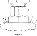
- Figure 1 is a side view of part of a fastener assembly passing through a composite panel 1.
- the assembly comprises an externally threaded bolt 2, an internally threaded nut 3, and a washer 4.
- sparking, plasma or out-gassing may occur at the locations 5 shown in Figure 1 .
- a known method of providing spark suppression is described in WO 2012/107741 .
- a volume of gas is enclosed by a cap around the fastener.
- the gas provides spark suppression for arcing that may occur between the composite structure and the metal fastener during any lightning strike.
- WO 2012/107741 describes a two-piece construction comprising an outer cap member and an inner cap member.
- the required quantity of sealant is measured into the base of the outer cap member and the inner cap member is then either partially nested within the outer cap and placed over one end of the fastener.
- the sealant is forced to flow between the inner and outer caps and exit from around the base of the outer cap over the surface of the structure.
- the sealant is distributed without voids between the inner and outer cap members, and a portion of sealant collects at the base of the outer cap member, to form a bead of sealant around the circumference of the cap, sufficient to adhere the cap to the structure when the sealant cures.
- the installation force increases approximately proportional to the cross sectional area and surface area of the space between the inner and outer caps and there is no mechanical advantage.
- an unreasonably high installation force is required to install the nut cap by hand.
- US 2012/219380 A1 discloses an insulated, sealed cap which overlies and protects a fastener component or the like on a substrate in association with a substrate opening.
- the sealed cap includes an outer cap component filled partially with a selected sealant material and assembled with an inner collet sized and shaped to fit with a slip fit about the fastener component such as a nut or the like at one side of a selected substrate, such as the skin of an aircraft.
- An inboard edge of the inner collet seats on and substantially seals with the substrate.
- the outer cap component is then displaced toward the substrate to extrude the sealant material into a thin and substantially uniform layer joined with an extruded outer bead on the substrate, and then permitted to cure. Tapered ribs on the inner collet effectively lock with the outer cap component during sealant material curing and subsequently.
- a first aspect of the invention provides a cap for forming a sealed cavity around one end of a fastener, the cap comprising an inner cap member with a base terminating at an edge which surrounds an opening into a central cavity; an outer cap member which fits over the inner cap member and has a base; and a sealant material between the inner cap member and the outer cap member, wherein either: the inner cap member has side walls with a substantially uniform wall thickness around the entire circumference of the inner cap member and a plurality of channels formed in an outer surface of the inner cap member and a plurality of corresponding ridges formed in an inner surface of the inner cap member, the channels and the ridges extending longitudinally along a substantial portion of the inner cap member; or the outer cap member has side walls with a substantially uniform wall thickness and a plurality of channels formed in an inner surface of the outer cap member and a corresponding plurality of ridges formed in an outer surface of the outer cap member, the channels and the ridges extending longitudinally along a substantial portion of the outer cap member.
- the plurality of channels form a path along which the sealant may flow more freely as compared to the nominal gap provided between the side walls of the inner and outer cap members. This is due to the reduced effect of friction of the sealant with the walls, thanks to the reduced sealant to wall contact for a given cross-sectional area of sealant flow.
- the invention is therefore particularly advantageous when applied to caps for larger diameter fasteners, e.g. fasteners larger than approximately 3 ⁇ 4" diameter, which may otherwise not be suitable for hand installation, but enables a reduced installation force for all fastener diameters.
- the size of the channels can be varied to control the amount of force required to install the nut cap.
- the channel depth may diminish towards the top of the cap. This further facilitates the motion of the sealant from the top of the cap to the base by providing a graduated channel and therefore decreases the installation force.. It also reduces the amount of sealant held near the top of the cap, where it is desirable to have only a thin film to ensure good adhesion of the entire surface of the outer surface of the inner cap member to the inner surface of the outer cap member.
- the channel width may flare outwardly towards the base.
- the flares may join to form a substantially annular aperture between the inner and outer cap members adjacent their respective bases. This arrangement further supports sealant flow and even distribution of sealant at the bond line with the structure.
- the plurality of longitudinal channels may emanate from a common point at the top of the cap. This encourages equal flow of sealant at all points around the circumference of the cap so reducing or eliminating voids formation in the sealant.
- the cap may have at least three locating features disposed around the inner surface of the inner cap member. These locating features ensure an interference fit of the inner cap with the one end of the fastener.
- the channels and corresponding ridges are on the inner cap member and the locating feature is the ridge on the inner surface of the inner cap member. This arrangement produces a point contact with the fastener and does not restrict out-gassing into the inner cavity.
- the inner cap member has the channels and ridges, and a cross-section of the side walls of the outer cap member when viewed longitudinally, is annular.
- the cross-section of the side walls of the inner cap member when viewed longitudinally is a repeating pattern of channels and ridges around the circumference of the inner cap member.
- the adjacent ones of the channels may meet forming a cusp.
- the adjacent ones of the channels may meet forming a crest between the channels, i.e. the channels meet without an abrupt change in curvature of the side wall.
- the channels may be circumferentially interspersed between regions where the inner and outer surfaces have constant diameter.
- the specific arrangements chosen will be a function of many factors, including for example fastener size, required adhesion properties and viscosity of uncured sealant. Whilst a repeating pattern of similar channels will often be preferred, an arrangement of dissimilar channels and/or dissimilar spacing between adjacent channels may be appropriate for some installations.
- the cross section of the channel when viewed in the longitudinal direction is substantially scallop shaped.
- the scalloped shape of the inner cap permits some radial stretching which enables an interference fit to be maintained over the tolerance range of the fastener base.
- the base of the outer cap member may form a flange extending outwardly from the inner cap member at a point which is set back from the edge of the base of the inner cap member so as to define a pocket between the flange and the base of the inner cap member. This arrangement provides a greater surface for the bead to adhere to the structure.
- the outer cap member has a substantially cylindrical side wall and the base of the outer cap member forms a flange extending outwardly from the inner cap member at a point which is set back from the edge of the base of the inner cap member so as to define a pocket between the flange and the base.
- the cap members may be substantially dome-shaped. This arrangement both minimizes stress concentrations and assists in the flow of sealant towards the structure.
- the cap members may be substantially top-hat shaped. This arrangement may facilitate storage of the cap in an inverted position.
- the outer surface of the inner cap member and the inner surface of the outer cap member may be substantially dome-shaped, whilst the inner surface of the inner cap member and/or the outer surface of the outer cap member may have a shape which is not dome-shaped, e.g. top-hat shaped.
- the cap members may be made of plastics material.
- the plastics material may be polyetherimide (PEI), for example.
- PEI polyetherimide
- Plastic materials are generally cheap, light and easy to form whilst having the required resilience for the application.
- the sealant material may be a material such as a two-part epoxy which is normally used in applications where its primary (or sole) purpose is to act as an adhesive.
- the sealant material may be a material such as poly-sulphide or silicone rubber which is normally used in applications where its primary (or sole) purpose is to act as a sealant. In the latter case the sealant material is typically an elastomer.
- a yet further aspect of the invention provides a method of installing a cap to form a sealed cavity around one end of a fastener, the fastener passing through a structure, the cap comprising an inner cap member with a base terminating at an edge which surrounds an opening into a central cavity; an outer cap member which fits over the inner cap member and has a base; and a sealant material between the inner cap member and the outer cap member, wherein either: the inner cap member has side walls with a substantially uniform wall thickness around the entire circumference of the inner cap member and a plurality of channels formed in an outer surface of the inner cap member and a plurality of corresponding ridges formed in an inner surface of the inner cap member, the channels and the ridges extending longitudinally along a substantial portion of the inner cap member; or the outer cap member has side walls with a substantially uniform wall thickness and a plurality of channels formed in an inner surface of the outer cap member and a corresponding plurality of ridges formed in an outer surface of the outer cap member, the channels and the ridges
- the inner cap can be fully installed on the fastener prior to installation of the outer cap over the inner cap.
- the inner cap may be partially nested within the outer cap so that the cap is partially engaged and the sealant material moves partially along the channels prior to installation over the fastener.
- the sealant material may be disposed inside the outer cap prior to installation over the fastener.
- the sealant material may be disposed over the outer surface of the inner cap prior to installation of the outer cap over the inner cap.
- Figure 2 is a side section view showing a metal bolt 10 passing through a composite panel 11.
- the panel has a raised feature 12 on one side, which may be for example fillets, ribs or spar caps.
- An internally threaded metal nut 13 is screwed onto the bolt 10 and has a convex spherical surface 14 which engages a concave spherical surface 15 of a washer 40.
- the spherical nut and washer enable the fastener to be securely fixed to the panel and permits angular misalignment if the bolt shank is not perpendicular to the panel.
- a spark containment cap is fitted over the fastener.
- the cap has a two-part construction with an outer cap 20 fit onto an inner cap 16 so that the inner cap 16 is nested within the outer cap 20.
- the caps 16, 20 have a domed shaped as indicated at 27 which reduces exposure to damage (for instance by being kicked by the foot of an installer) and minimises stress concentration.
- the caps 16, 20 are formed from a polymer such as polyetherimide ULTEM 2400.
- the inner cap 16 has a base 17 terminating at an edge 18 which surrounds an opening into a central cavity 19 which contains the nut 13, bolt 10 and washer 40.
- the upper part of the outer cap 20 has a domed shape and is bonded to the inner cap 16 by a thin two-part epoxy interfay adhesive layer 21.
- the interfay adhesive layer 21 between the inner and outer caps creates a bonded double layer with enhanced flexibility and strength.
- the lower part of the outer cap 20 has a flared base (or skirt) 22 which forms an annular flange extending outwardly from the inner cap 16.
- the point 23 where the flange 22 begins to extend outwardly from the cap 16 is set back vertically from the edge 18 of the base 17.
- An annular sealant pocket 24 between the flange 22 and the base 17 is filled with the same two-part epoxy sealant as the interfay layer 21.
- the cap may be immersed in fuel, in which case the sealant also prevents the ingress of fuel into the main cavity 19.
- the inner cap member 16 has a side wall 28 with a substantially uniform wall thickness around the entire circumference of the inner cap member 16.
- the side walls 28 are generally cylindrical but have eight identical and evenly distributed channels 26 formed in an outer surface 27 thereof and eight corresponding ridges 29 formed in an inner surface 30 thereof.
- the cross section of the channels 26 when viewed in the longitudinal direction is substantially scallop shaped.
- the channels 26 and ridges 29 extend longitudinally towards the base 18 of the inner cap member 16. Each channel and ridge pair is separated from their adjacent channel and ridge pairs by regions where the inner and outer surfaces of the inner cap member 20 have constant diameter.
- the outer surface of the side wall 28 inner cap member 16 intermediate the channels 26 is sized to form a clearance fit with the inner surface of the side wall of the outer cap member 20. This clearance fit centralizes and orientates the outer cap.
- the eight ridges 29 of the inner cap member 16 engage the washer 40 at eight single point of contact locations and allow the inner cap member 16 to flex to accommodate expansion around the washer.
- the cap By locating the cap on the washer 40, the cap can be installed against the surface of the structure 11 even if the bolt 10 is not perpendicular to the surface, i.e. the surface is a sloping surface.
- caps are principally bonded together by the domed interfay adhesive layer 21 which is located outside the pocket 24, but they are also bonded together by the sealant within the pocket 24.
- the caps 16, 20 are supplied as a kit of parts.
- a metered quantity of two-part epoxy sealant is provided between the inner and outer caps.
- a poly-sulphide sealant may be used, optionally in a frozen state.
- the inner cap 16 is pushed onto the fastener assembly with the ridges 29 acting as location lugs to engage the washer 40 as a slight interference fit and the edge 18 of the cap engaging the panel 11. The interference fit prevents the inner cap from falling off under the action of gravity if the panel 11 is downward facing.
- the outer cap 20 is pushed over the inner cap 16.
- the two-part epoxy sealant is squeezed between the outer and inner caps and flows predominantly via the channels 26 down to the base of the cap, completely filling the pocket 24 without entering the central cavity.
- the channels form a path along which the sealant may flow more freely as compared to the nominal gap provided between the side walls of the inner and outer caps. This is due to the reduced effect of friction of the sealant with the walls, thanks to the reduced sealant to wall contact for a given cross-sectional area of sealant flow.
- the number of channels may be increased.
- the number of channels may be increased to twelve, or indeed any other suitable number.
- the increased number of channels may aid distribution of the sealant at the bond line.
- the greater the number of channels the greater the sealant to wall contact for a given cross-sectional area of sealant flow, and so an optimal number of channels for a particular channel depth can be selected for a given installation force.
- the ratio of the channel size to the diameter of the outer cap cavity can be tailored to produce a mechanical advantage, i.e. the same amount of sealant can be dispensed over a longer stroke length during as the outer cap is sleeved over the inner cap.
- the channel width may flare outwardly towards the base.
- the flares may join to form a substantially annular aperture between the inner and outer cap members adjacent their respective bases. This arrangement further supports sealant flow and even distribution of sealant at the bond line with the structure.
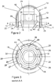
- FIGS 4 and 5 illustrate a second embodiment of the spark containment cap.
- Like reference numerals have been used to denote like parts with the first embodiment of Figures 2 and 3 and only the differences will be described in the following.
- the second embodiment differs only in that the side wall of the inner cap 116 has channels 126 and corresponding ridges 129 which extend to the top of the inner cap, and the depth of the channels diminishes towards the top of the cap.
- the channels 126 emanate from a common point at the top of the cap. This may decrease the installation force and help ensure even supply of sealant along each channel. Installation of the spark containment cap of the second embodiment can be effected in an identical manner to that described above with reference to the first embodiment.
- FIG. 6 illustrates a third embodiment of the spark containment cap.
- Like reference numerals have been used to denote like parts with the first embodiment of Figures 2 and 3 and only the differences will be described in the following.
- the third embodiment differs only in that the side wall of the inner cap 216 has channels and ridges 226, 227 formed continuously around the circumference of the inner cap, and not interspersed between regions where the inner and outer surfaces of the inner cap member have constant diameter.
- the channels 226 in the outer surface of the inner cap are generally v-shaped so forming a cusp at the base of each channel, which defines the ridge 227 of the reverse (inner) surface of the inner cap.
- the adjacent channels 226 meet at a crest with a substantially continuous curvature defining the maximum outer diameter of the inner cap.
- the crests form a clearance fit with the inner surface of the outer cap.
- the channels and ridges are continuous around the circumference of the inner cap member and the crest of one channel meets the cusp of the adjacent channel, so as to approximate a sinusoidal wave around the circumference of the inner cap.
- Figure 7 illustrates a fourth embodiment of the spark containment cap.
- the fourth embodiment differs in that the inner cap 416 has a substantially cylindrical side wall and the outer cap 420 has a faceted side wall.
- the outer cap 420 may have any number of facets three or greater, and in the particular example shown in Figure 7 has an octagonal section with eight facets.
- eight channels 426 are formed between the outer surface of the inner cap and the inner surface of the outer cap.
- the channels function in a substantially identical manner to that described above to facilitate the flow of the sealant material towards the base of the cap.
- the faceted side wall of the outer cap may be formed as any regular polygon, or alternatively may be formed as an irregular polygon, or a star-shaped polygon.
- a plurality of locating lugs or ridges 427 are formed extending inwardly at regularly spaced locations around the inner surface of the inner cap. In the particular example shown in Figure 7 there are 8 locating lugs 427 but any number of lugs three or greater may be provided. These engage the washer 40 as a slight interference fit to prevent the inner cap from falling off under the action of gravity if installed upside down. Installation of the spark containment cap of the fourth embodiment can be effected in an identical manner to that described above with reference to the first embodiment.
Description
- The present invention relates to a cap for forming a sealed cavity around one end of a fastener and a method of installing such a cap.
-
Figure 1 is a side view of part of a fastener assembly passing through a composite panel 1. The assembly comprises an externally threaded bolt 2, an internally threaded nut 3, and a washer 4. In the event of a lightning strike hitting the composite panel 1 and attaching to the fastener, sparking, plasma or out-gassing may occur at thelocations 5 shown inFigure 1 . - A known method of providing spark suppression is described in
WO 2012/107741 . A volume of gas is enclosed by a cap around the fastener. The gas provides spark suppression for arcing that may occur between the composite structure and the metal fastener during any lightning strike. -
WO 2012/107741 describes a two-piece construction comprising an outer cap member and an inner cap member. In one example the required quantity of sealant is measured into the base of the outer cap member and the inner cap member is then either partially nested within the outer cap and placed over one end of the fastener. By exerting hand pressure to urge the outer cap over the inner cap, towards the structure, the sealant is forced to flow between the inner and outer caps and exit from around the base of the outer cap over the surface of the structure. - Ideally, the sealant is distributed without voids between the inner and outer cap members, and a portion of sealant collects at the base of the outer cap member, to form a bead of sealant around the circumference of the cap, sufficient to adhere the cap to the structure when the sealant cures.
- The installation force increases approximately proportional to the cross sectional area and surface area of the space between the inner and outer caps and there is no mechanical advantage. On larger installations, e.g. fasteners larger than approximately ¾" diameter, an unreasonably high installation force is required to install the nut cap by hand.
-
US 2012/219380 A1 discloses an insulated, sealed cap which overlies and protects a fastener component or the like on a substrate in association with a substrate opening. The sealed cap includes an outer cap component filled partially with a selected sealant material and assembled with an inner collet sized and shaped to fit with a slip fit about the fastener component such as a nut or the like at one side of a selected substrate, such as the skin of an aircraft. An inboard edge of the inner collet seats on and substantially seals with the substrate. The outer cap component is then displaced toward the substrate to extrude the sealant material into a thin and substantially uniform layer joined with an extruded outer bead on the substrate, and then permitted to cure. Tapered ribs on the inner collet effectively lock with the outer cap component during sealant material curing and subsequently. - A first aspect of the invention provides a cap for forming a sealed cavity around one end of a fastener, the cap comprising an inner cap member with a base terminating at an edge which surrounds an opening into a central cavity; an outer cap member which fits over the inner cap member and has a base; and a sealant material between the inner cap member and the outer cap member, wherein either: the inner cap member has side walls with a substantially uniform wall thickness around the entire circumference of the inner cap member and a plurality of channels formed in an outer surface of the inner cap member and a plurality of corresponding ridges formed in an inner surface of the inner cap member, the channels and the ridges extending longitudinally along a substantial portion of the inner cap member; or the outer cap member has side walls with a substantially uniform wall thickness and a plurality of channels formed in an inner surface of the outer cap member and a corresponding plurality of ridges formed in an outer surface of the outer cap member, the channels and the ridges extending longitudinally along a substantial portion of the outer cap member.
- The plurality of channels form a path along which the sealant may flow more freely as compared to the nominal gap provided between the side walls of the inner and outer cap members. This is due to the reduced effect of friction of the sealant with the walls, thanks to the reduced sealant to wall contact for a given cross-sectional area of sealant flow. The invention is therefore particularly advantageous when applied to caps for larger diameter fasteners, e.g. fasteners larger than approximately ¾" diameter, which may otherwise not be suitable for hand installation, but enables a reduced installation force for all fastener diameters.
- The size of the channels can be varied to control the amount of force required to install the nut cap.
- The channel depth may diminish towards the top of the cap. This further facilitates the motion of the sealant from the top of the cap to the base by providing a graduated channel and therefore decreases the installation force.. It also reduces the amount of sealant held near the top of the cap, where it is desirable to have only a thin film to ensure good adhesion of the entire surface of the outer surface of the inner cap member to the inner surface of the outer cap member.
- The channel width may flare outwardly towards the base. The flares may join to form a substantially annular aperture between the inner and outer cap members adjacent their respective bases. This arrangement further supports sealant flow and even distribution of sealant at the bond line with the structure.
- The plurality of longitudinal channels may emanate from a common point at the top of the cap. This encourages equal flow of sealant at all points around the circumference of the cap so reducing or eliminating voids formation in the sealant.
- The cap may have at least three locating features disposed around the inner surface of the inner cap member. These locating features ensure an interference fit of the inner cap with the one end of the fastener.
- In a preferred embodiment the channels and corresponding ridges are on the inner cap member and the locating feature is the ridge on the inner surface of the inner cap member. This arrangement produces a point contact with the fastener and does not restrict out-gassing into the inner cavity.
- In a preferred embodiment the inner cap member has the channels and ridges, and a cross-section of the side walls of the outer cap member when viewed longitudinally, is annular.
- In a preferred embodiment the cross-section of the side walls of the inner cap member when viewed longitudinally, is a repeating pattern of channels and ridges around the circumference of the inner cap member. The adjacent ones of the channels may meet forming a cusp. In another preferred embodiment the adjacent ones of the channels may meet forming a crest between the channels, i.e. the channels meet without an abrupt change in curvature of the side wall. In yet another preferred embodiment the channels may be circumferentially interspersed between regions where the inner and outer surfaces have constant diameter. The specific arrangements chosen will be a function of many factors, including for example fastener size, required adhesion properties and viscosity of uncured sealant. Whilst a repeating pattern of similar channels will often be preferred, an arrangement of dissimilar channels and/or dissimilar spacing between adjacent channels may be appropriate for some installations.
- The cross section of the channel when viewed in the longitudinal direction is substantially scallop shaped. The scalloped shape of the inner cap permits some radial stretching which enables an interference fit to be maintained over the tolerance range of the fastener base.
- The base of the outer cap member may form a flange extending outwardly from the inner cap member at a point which is set back from the edge of the base of the inner cap member so as to define a pocket between the flange and the base of the inner cap member. This arrangement provides a greater surface for the bead to adhere to the structure.
- In a preferred embodiment of the present invention the outer cap member has a substantially cylindrical side wall and the base of the outer cap member forms a flange extending outwardly from the inner cap member at a point which is set back from the edge of the base of the inner cap member so as to define a pocket between the flange and the base.
- The cap members may be substantially dome-shaped. This arrangement both minimizes stress concentrations and assists in the flow of sealant towards the structure.
- Alternatively the cap members may be substantially top-hat shaped. This arrangement may facilitate storage of the cap in an inverted position.
- Alternatively the outer surface of the inner cap member and the inner surface of the outer cap member may be substantially dome-shaped, whilst the inner surface of the inner cap member and/or the outer surface of the outer cap member may have a shape which is not dome-shaped, e.g. top-hat shaped.
- The cap members may be made of plastics material. The plastics material may be polyetherimide (PEI), for example. Plastic materials are generally cheap, light and easy to form whilst having the required resilience for the application.
- The sealant material may be a material such as a two-part epoxy which is normally used in applications where its primary (or sole) purpose is to act as an adhesive. Alternatively the sealant material may be a material such as poly-sulphide or silicone rubber which is normally used in applications where its primary (or sole) purpose is to act as a sealant. In the latter case the sealant material is typically an elastomer.
- A yet further aspect of the invention provides a method of installing a cap to form a sealed cavity around one end of a fastener, the fastener passing through a structure, the cap comprising an inner cap member with a base terminating at an edge which surrounds an opening into a central cavity; an outer cap member which fits over the inner cap member and has a base; and a sealant material between the inner cap member and the outer cap member, wherein either: the inner cap member has side walls with a substantially uniform wall thickness around the entire circumference of the inner cap member and a plurality of channels formed in an outer surface of the inner cap member and a plurality of corresponding ridges formed in an inner surface of the inner cap member, the channels and the ridges extending longitudinally along a substantial portion of the inner cap member; or the outer cap member has side walls with a substantially uniform wall thickness and a plurality of channels formed in an inner surface of the outer cap member and a corresponding plurality of ridges formed in an outer surface of the outer cap member, the channels and the ridges extending longitudinally along a substantial portion of the outer cap member, said method comprising the steps of: (a) fitting the cap over one end of the fastener so that the end of the fastener is enclosed by the inner cap member and a plurality of channels are defined between the inner and outer cap members; (b) pushing the outer cap member towards the structure so that the sealant material flows substantially via the channels towards the structure so as to form a bead of sealant around the base of the cap; and (c) adhering the cap to the structure with the sealant material.
- In the method, the inner cap can be fully installed on the fastener prior to installation of the outer cap over the inner cap. Alternatively the inner cap may be partially nested within the outer cap so that the cap is partially engaged and the sealant material moves partially along the channels prior to installation over the fastener. The sealant material may be disposed inside the outer cap prior to installation over the fastener. Alternatively, the sealant material may be disposed over the outer surface of the inner cap prior to installation of the outer cap over the inner cap.
- Embodiments of the invention will now be described with reference to the accompanying drawings, in which:
-
Figure 1 is a side view of a nut and bolt assembly; -
Figure 2 is a side section view of a fastener assembly and spark containment cap according to a first embodiment of the invention; -
Figure 3 is a cross-sectional view of the assembly ofFigure 2 along A-A; -
Figure 4 is a side section view of a fastener assembly and spark containment cap according to a second embodiment of the invention; -
Figure 5 is a cross-sectional view of the assembly ofFigure 4 along B-B; and -
Figure 6 is a cross-sectional view of a fastener assembly and spark containment cap according to a third embodiment of the invention. -
Figure 7 is a cross-sectional view of a fastener assembly and spark containment cap according to a fourth embodiment of the invention. -
Figure 2 is a side section view showing ametal bolt 10 passing through acomposite panel 11. The panel has a raisedfeature 12 on one side, which may be for example fillets, ribs or spar caps. An internally threadedmetal nut 13 is screwed onto thebolt 10 and has a convexspherical surface 14 which engages a concavespherical surface 15 of awasher 40. The spherical nut and washer enable the fastener to be securely fixed to the panel and permits angular misalignment if the bolt shank is not perpendicular to the panel. - A spark containment cap is fitted over the fastener. The cap has a two-part construction with an
outer cap 20 fit onto aninner cap 16 so that theinner cap 16 is nested within theouter cap 20. Thecaps caps inner cap 16 has a base 17 terminating at anedge 18 which surrounds an opening into acentral cavity 19 which contains thenut 13,bolt 10 andwasher 40. The upper part of theouter cap 20 has a domed shape and is bonded to theinner cap 16 by a thin two-part epoxyinterfay adhesive layer 21. Theinterfay adhesive layer 21 between the inner and outer caps creates a bonded double layer with enhanced flexibility and strength. - The lower part of the
outer cap 20 has a flared base (or skirt) 22 which forms an annular flange extending outwardly from theinner cap 16. Thepoint 23 where theflange 22 begins to extend outwardly from thecap 16 is set back vertically from theedge 18 of thebase 17. Anannular sealant pocket 24 between theflange 22 and thebase 17 is filled with the same two-part epoxy sealant as theinterfay layer 21. The sealant in thesealant pocket 24 bonds thecaps panel 11 and the sealedmain cavity 19 contains any sparking, plasma or out-gassing caused by a lightning strike. The cap may be immersed in fuel, in which case the sealant also prevents the ingress of fuel into themain cavity 19. - As best shown in the section view A-A of
Figure 3 theinner cap member 16 has aside wall 28 with a substantially uniform wall thickness around the entire circumference of theinner cap member 16. Theside walls 28 are generally cylindrical but have eight identical and evenly distributedchannels 26 formed in anouter surface 27 thereof and eight correspondingridges 29 formed in aninner surface 30 thereof. The cross section of thechannels 26 when viewed in the longitudinal direction is substantially scallop shaped. - The
channels 26 andridges 29 extend longitudinally towards thebase 18 of theinner cap member 16. Each channel and ridge pair is separated from their adjacent channel and ridge pairs by regions where the inner and outer surfaces of theinner cap member 20 have constant diameter. The outer surface of theside wall 28inner cap member 16 intermediate thechannels 26 is sized to form a clearance fit with the inner surface of the side wall of theouter cap member 20. This clearance fit centralizes and orientates the outer cap. - The eight
ridges 29 of theinner cap member 16 engage thewasher 40 at eight single point of contact locations and allow theinner cap member 16 to flex to accommodate expansion around the washer. - By locating the cap on the
washer 40, the cap can be installed against the surface of thestructure 11 even if thebolt 10 is not perpendicular to the surface, i.e. the surface is a sloping surface. - Note that the caps are principally bonded together by the domed
interfay adhesive layer 21 which is located outside thepocket 24, but they are also bonded together by the sealant within thepocket 24. - A method of installing the spark containment cap of
Figures 2 and 3 will now be described. Thecaps inner cap 16 is pushed onto the fastener assembly with theridges 29 acting as location lugs to engage thewasher 40 as a slight interference fit and theedge 18 of the cap engaging thepanel 11. The interference fit prevents the inner cap from falling off under the action of gravity if thepanel 11 is downward facing. - Next, the
outer cap 20 is pushed over theinner cap 16. The two-part epoxy sealant is squeezed between the outer and inner caps and flows predominantly via thechannels 26 down to the base of the cap, completely filling thepocket 24 without entering the central cavity. The channels form a path along which the sealant may flow more freely as compared to the nominal gap provided between the side walls of the inner and outer caps. This is due to the reduced effect of friction of the sealant with the walls, thanks to the reduced sealant to wall contact for a given cross-sectional area of sealant flow. - To improve the flow of sealant between the inner and outer caps the number of channels (and corresponding ridges) may be increased. For example, instead of the eight channels shown in the embodiment of
Figures 2 and 3 the number of channels may be increased to twelve, or indeed any other suitable number. The increased number of channels may aid distribution of the sealant at the bond line. Of course, the greater the number of channels the greater the sealant to wall contact for a given cross-sectional area of sealant flow, and so an optimal number of channels for a particular channel depth can be selected for a given installation force. The ratio of the channel size to the diameter of the outer cap cavity can be tailored to produce a mechanical advantage, i.e. the same amount of sealant can be dispensed over a longer stroke length during as the outer cap is sleeved over the inner cap. - The channel width may flare outwardly towards the base. The flares may join to form a substantially annular aperture between the inner and outer cap members adjacent their respective bases. This arrangement further supports sealant flow and even distribution of sealant at the bond line with the structure.
-
Figures 4 and 5 illustrate a second embodiment of the spark containment cap. Like reference numerals have been used to denote like parts with the first embodiment ofFigures 2 and 3 and only the differences will be described in the following. The second embodiment differs only in that the side wall of theinner cap 116 haschannels 126 andcorresponding ridges 129 which extend to the top of the inner cap, and the depth of the channels diminishes towards the top of the cap. Thechannels 126 emanate from a common point at the top of the cap. This may decrease the installation force and help ensure even supply of sealant along each channel. Installation of the spark containment cap of the second embodiment can be effected in an identical manner to that described above with reference to the first embodiment. -
Figure 6 illustrates a third embodiment of the spark containment cap. Like reference numerals have been used to denote like parts with the first embodiment ofFigures 2 and 3 and only the differences will be described in the following. The third embodiment differs only in that the side wall of theinner cap 216 has channels andridges - The
channels 226 in the outer surface of the inner cap are generally v-shaped so forming a cusp at the base of each channel, which defines theridge 227 of the reverse (inner) surface of the inner cap. Theadjacent channels 226 meet at a crest with a substantially continuous curvature defining the maximum outer diameter of the inner cap. The crests form a clearance fit with the inner surface of the outer cap. Installation of the spark containment cap of the third embodiment can be effected in an identical manner to that described above with reference to the first embodiment. - In another alternate embodiment (not shown), the channels and ridges are continuous around the circumference of the inner cap member and the crest of one channel meets the cusp of the adjacent channel, so as to approximate a sinusoidal wave around the circumference of the inner cap.
-
Figure 7 illustrates a fourth embodiment of the spark containment cap. Like reference numerals have been used to denote like parts with the first embodiment ofFigures 2 and 3 and only the differences will be described in the following. The fourth embodiment differs in that the inner cap 416 has a substantially cylindrical side wall and theouter cap 420 has a faceted side wall. Theouter cap 420 may have any number of facets three or greater, and in the particular example shown inFigure 7 has an octagonal section with eight facets. When the inner cap is nested within the outer cap eightchannels 426 are formed between the outer surface of the inner cap and the inner surface of the outer cap. The channels function in a substantially identical manner to that described above to facilitate the flow of the sealant material towards the base of the cap. - The faceted side wall of the outer cap may be formed as any regular polygon, or alternatively may be formed as an irregular polygon, or a star-shaped polygon.
- A plurality of locating lugs or
ridges 427 are formed extending inwardly at regularly spaced locations around the inner surface of the inner cap. In the particular example shown inFigure 7 there are 8 locating lugs 427 but any number of lugs three or greater may be provided. These engage thewasher 40 as a slight interference fit to prevent the inner cap from falling off under the action of gravity if installed upside down. Installation of the spark containment cap of the fourth embodiment can be effected in an identical manner to that described above with reference to the first embodiment. - Any features of the first to fourth embodiments described above may be appropriately combined. For example, flaring of the channels adjacent the base of the cap to aid sealant distribution at the bond line may be incorporated into any of the embodiments.
- Although the invention has been described above with reference to one or more preferred embodiments, it will be appreciated that various changes or modifications may be made without departing from the scope of the invention as defined in the appended claims.
Claims (14)
- A cap for forming a sealed cavity around one end of a fastener, the cap comprising an inner cap member (16) with a base terminating at an edge which surrounds an opening into a central cavity (19); and an outer cap member (20) which fits over the inner cap member and has a base; and a sealant material between the inner cap member and the outer cap member, characterised in that either: the inner cap member has side walls with a substantially uniform wall thickness around the entire circumference of the inner cap member and a plurality of channels (26) formed in an outer surface of the inner cap member and a plurality of corresponding ridges (29) formed in an inner surface of the inner cap member, the channels and the ridges extending longitudinally along a substantial portion of the inner cap member; or the outer cap member has side walls with a substantially uniform wall thickness and a plurality of channels formed in an inner surface of the outer cap member and a corresponding plurality of ridges formed in an outer surface of the outer cap member, the channels and the ridges extending longitudinally along a substantial portion of the outer cap member.
- A cap according to claim 1, wherein the channel depth diminishes towards the top of the cap.
- A cap according to any preceding claim, wherein the channel width flares outwardly towards the base.
- A cap according to claim 3, wherein the channel flares join to form a substantially annular aperture between the inner and outer cap members adjacent their respective bases.
- A cap according to any preceding claim, wherein the plurality of longitudinal channels (26) emanate from a common point at the top of the cap.
- A cap according to any preceding claim having at least three locating features disposed around the inner surface of the inner cap member.
- A cap according to claim 6, wherein the channels and corresponding ridges are on the inner cap member and the locating features are the ridges (29) on the inner surface of the inner cap member.
- A cap according to any preceding claim, wherein the inner cap member (16) has the channels and ridges, and a cross-section of the side walls of the outer cap member when viewed longitudinally, is annular.
- A cap according to claim 8, wherein a cross-section of the side walls of the inner cap member when viewed longitudinally, is a repeating pattern of channels (26) and ridges (29) around the circumference of the inner cap member.
- A cap according to claim 9, wherein the channels are circumferentially interspersed between regions where the inner and outer surfaces of the inner cap have constant diameter.
- A cap according to any preceding claim, wherein the cross section of the channel when viewed in the longitudinal direction is substantially scallop shaped.
- A cap according to any preceding claim, wherein the base of the outer cap member forms a flange (22) extending outwardly from the inner cap member at a point which is set back from the edge of the base of the inner cap member so as to define a pocket between the flange and the base of the inner cap member.
- A cap according to any preceding claim, wherein the cap members are substantially dome-shaped.
- A method of installing a cap to form a sealed cavity around one end of a fastener, the fastener passing through a structure, the cap comprising an inner cap member (16) with a base terminating at an edge which surrounds an opening into a central cavity; an outer cap member (20) which fits over the inner cap member and has a base; and a sealant material between the inner cap member and the outer cap member, wherein either: the inner cap member has side walls with a substantially uniform wall thickness around the entire circumference of the inner cap member and a plurality of channels (26) formed in an outer surface of the inner cap member and a plurality of corresponding ridges (29) formed in an inner surface of the inner cap member, the channels and the ridges extending longitudinally along a substantial portion of the inner cap member; or the outer cap member has side walls with a substantially uniform wall thickness and a plurality of channels formed in an inner surface of the outer cap member and a corresponding plurality of ridges formed in an outer surface of the outer cap member, the channels and the ridges extending longitudinally along a substantial portion of the outer cap member, said method comprising the steps of: (a) fitting the cap over one end of the fastener so that the end of the fastener is enclosed by the inner cap member and a plurality of channels are defined between the inner and outer cap members; (b) pushing the outer cap member towards the structure so that the sealant material flows substantially via the channels towards the structure so as to form a bead of sealant around the base of the cap; and (c) adhering the cap to the structure with the sealant material.
Applications Claiming Priority (2)
| Application Number | Priority Date | Filing Date | Title |
|---|---|---|---|
| GBGB1220002.8A GB201220002D0 (en) | 2012-11-06 | 2012-11-06 | Cap with channels for forming a sealed cavity around fastener |
| PCT/GB2013/052868 WO2014072687A2 (en) | 2012-11-06 | 2013-11-01 | Cap with channels for forming a sealed cavity around fastener |
Publications (2)
| Publication Number | Publication Date |
|---|---|
| EP2917110A2 EP2917110A2 (en) | 2015-09-16 |
| EP2917110B1 true EP2917110B1 (en) | 2019-08-28 |
Family
ID=47429273
Family Applications (1)
| Application Number | Title | Priority Date | Filing Date |
|---|---|---|---|
| EP13786734.7A Active EP2917110B1 (en) | 2012-11-06 | 2013-11-01 | Cap with channels for forming a sealed cavity around fastener |
Country Status (7)
| Country | Link |
|---|---|
| US (2) | US9599141B2 (en) |
| EP (1) | EP2917110B1 (en) |
| JP (1) | JP2016502039A (en) |
| CN (1) | CN104768850A (en) |
| CA (1) | CA2890051A1 (en) |
| GB (1) | GB201220002D0 (en) |
| WO (1) | WO2014072687A2 (en) |
Families Citing this family (12)
| Publication number | Priority date | Publication date | Assignee | Title |
|---|---|---|---|---|
| EP2989335B1 (en) * | 2013-04-22 | 2018-04-04 | PRC-Desoto International, Inc. | Sealant caps including internal barrier rings |
| US9541118B2 (en) | 2013-09-23 | 2017-01-10 | The Boeing Company | Systems and methods for use in covering a portion of a fastener protruding from a surface |
| GB2523125B (en) | 2014-02-13 | 2016-10-19 | Airbus Operations Ltd | Lobed nut cap |
| GB2535519A (en) | 2015-02-20 | 2016-08-24 | Airbus Operations Ltd | Two part cap |
| US10087974B2 (en) | 2016-12-06 | 2018-10-02 | David Szymczak | Protection cap assembly for one or more bolts |
| GB2568890A (en) * | 2017-11-29 | 2019-06-05 | Airbus Operations Ltd | Spark containment cap |
| GB2569315A (en) * | 2017-12-13 | 2019-06-19 | Airbus Operations Ltd | Assembly with captive nut |
| GB2572376A (en) | 2018-03-28 | 2019-10-02 | Airbus Operations Ltd | Cap with sealant flow path |
| GB2572377A (en) * | 2018-03-28 | 2019-10-02 | Airbus Operations Ltd | Cap with sealant flow path |
| US10800468B2 (en) * | 2018-08-02 | 2020-10-13 | Ford Global Technologies, Llc | Fifth-wheel assembly |
| US10982704B2 (en) * | 2019-01-03 | 2021-04-20 | The Boeing Company | EME protection cap system with screw sealant mechanism |
| GB202017193D0 (en) * | 2020-10-29 | 2020-12-16 | Airbus Operations Ltd | Spark containment cap |
Family Cites Families (14)
| Publication number | Priority date | Publication date | Assignee | Title |
|---|---|---|---|---|
| FI863590A (en) * | 1985-09-13 | 1987-03-14 | Confon Ag | GLIDSKYDDSANORDNING SPECIELLT FOER LUFTFYLLDA FORDONSDAECK PAO IS- OCH SNOEYTOR SAMT ADAPTER FOER SKRUVHUVUDEN OCH LIKNANDE. |
| US4826380A (en) * | 1988-01-19 | 1989-05-02 | Ltv Aerospace & Defense Company | Pre-cast sealant dome and method |
| US4905931A (en) * | 1988-02-18 | 1990-03-06 | The Boeing Company | Arc suppression around fasteners |
| US5082409A (en) * | 1990-10-26 | 1992-01-21 | Aluminum Company Of America | Vehicular lug nut cover and clip |
| US5810532A (en) * | 1997-05-09 | 1998-09-22 | Grand General Accessories Manufacturing Inc. | Vehicle lug nut covers |
| US6398471B1 (en) * | 2000-06-15 | 2002-06-04 | Illinois Tool Works Inc. | Utility lug nut tension indicator |
| US6318942B1 (en) * | 2000-08-16 | 2001-11-20 | Mckechnie Vehicle Components (Usa), Inc. | Lug cap having retention detents |
| ITTO20010468A1 (en) * | 2001-05-18 | 2002-11-18 | Ruspa S P A | COVER ELEMENT FOR THREADED CONNECTION DEVICE. |
| GB0128820D0 (en) * | 2001-12-01 | 2002-01-23 | Matrice Material Systems Ltd | Fixing cover |
| US20050100425A1 (en) * | 2003-11-07 | 2005-05-12 | Hung-Ming Wu | Fastener assembly |
| US8366367B2 (en) * | 2008-12-30 | 2013-02-05 | Brian Matlock | Nut and bolt cover |
| JP5610758B2 (en) | 2009-04-02 | 2014-10-22 | 三菱航空機株式会社 | Lightning-resistant fastener, cap, lightning-fastener installation method, aircraft |
| EP3366593B1 (en) * | 2011-02-10 | 2019-10-23 | Airbus Operations Limited | Cap for forming sealed cavity around fastener |
| US8388293B2 (en) * | 2011-02-28 | 2013-03-05 | Physical Systems, Inc. | Insulated and sealed cap for a fastener component |
-
2012
- 2012-11-06 GB GBGB1220002.8A patent/GB201220002D0/en not_active Ceased
-
2013
- 2013-11-01 CN CN201380058060.2A patent/CN104768850A/en active Pending
- 2013-11-01 US US14/440,714 patent/US9599141B2/en not_active Expired - Fee Related
- 2013-11-01 CA CA2890051A patent/CA2890051A1/en not_active Abandoned
- 2013-11-01 JP JP2015540212A patent/JP2016502039A/en not_active Withdrawn
- 2013-11-01 EP EP13786734.7A patent/EP2917110B1/en active Active
- 2013-11-01 WO PCT/GB2013/052868 patent/WO2014072687A2/en active Application Filing
-
2017
- 2017-02-02 US US15/423,111 patent/US10240628B2/en active Active
Non-Patent Citations (1)
| Title |
|---|
| None * |
Also Published As
| Publication number | Publication date |
|---|---|
| CA2890051A1 (en) | 2014-05-15 |
| GB201220002D0 (en) | 2012-12-19 |
| CN104768850A (en) | 2015-07-08 |
| EP2917110A2 (en) | 2015-09-16 |
| US20150300397A1 (en) | 2015-10-22 |
| US20170146048A1 (en) | 2017-05-25 |
| US10240628B2 (en) | 2019-03-26 |
| WO2014072687A2 (en) | 2014-05-15 |
| US9599141B2 (en) | 2017-03-21 |
| JP2016502039A (en) | 2016-01-21 |
| WO2014072687A3 (en) | 2014-07-10 |
Similar Documents
| Publication | Publication Date | Title |
|---|---|---|
| EP2917110B1 (en) | Cap with channels for forming a sealed cavity around fastener | |
| US8894338B2 (en) | Flanged cap for forming sealed cavity around fastener | |
| EP2673193B1 (en) | Cap for forming sealed cavity around fastener | |
| US9764854B2 (en) | Cap to accommodate washers | |
| US11130591B2 (en) | Lobed nut cap | |
| US8388293B2 (en) | Insulated and sealed cap for a fastener component | |
| US8882423B2 (en) | Lightning-resistant fastener and mounting structure of lightning-resistant fastener | |
| WO2014118510A1 (en) | Fastener cap assembly | |
| US9290276B2 (en) | Lightning protection fastener and aircraft | |
| JP2011098675A (en) | Thunder resistant fastener, cap, fastener member and installation method of thunder resistant fastener | |
| US11125263B2 (en) | Cap with sealant flow path | |
| WO2014118509A1 (en) | Cap assembly | |
| US20080237238A1 (en) | Closure and package with flexible base wall panel | |
| US10053855B2 (en) | Cluster cap sealing mechanism and method | |
| US20160131169A1 (en) | Fastening element | |
| GB2520774A (en) | Cap with injected sealant |
Legal Events
| Date | Code | Title | Description |
|---|---|---|---|
| PUAI | Public reference made under article 153(3) epc to a published international application that has entered the european phase |
Free format text: ORIGINAL CODE: 0009012 |
|
| 17P | Request for examination filed |
Effective date: 20150508 |
|
| AK | Designated contracting states |
Kind code of ref document: A2 Designated state(s): AL AT BE BG CH CY CZ DE DK EE ES FI FR GB GR HR HU IE IS IT LI LT LU LV MC MK MT NL NO PL PT RO RS SE SI SK SM TR |
|
| AX | Request for extension of the european patent |
Extension state: BA ME |
|
| DAX | Request for extension of the european patent (deleted) | ||
| STAA | Information on the status of an ep patent application or granted ep patent |
Free format text: STATUS: EXAMINATION IS IN PROGRESS |
|
| 17Q | First examination report despatched |
Effective date: 20180419 |
|
| GRAP | Despatch of communication of intention to grant a patent |
Free format text: ORIGINAL CODE: EPIDOSNIGR1 |
|
| STAA | Information on the status of an ep patent application or granted ep patent |
Free format text: STATUS: GRANT OF PATENT IS INTENDED |
|
| INTG | Intention to grant announced |
Effective date: 20190321 |
|
| GRAS | Grant fee paid |
Free format text: ORIGINAL CODE: EPIDOSNIGR3 |
|
| GRAA | (expected) grant |
Free format text: ORIGINAL CODE: 0009210 |
|
| STAA | Information on the status of an ep patent application or granted ep patent |
Free format text: STATUS: THE PATENT HAS BEEN GRANTED |
|
| AK | Designated contracting states |
Kind code of ref document: B1 Designated state(s): AL AT BE BG CH CY CZ DE DK EE ES FI FR GB GR HR HU IE IS IT LI LT LU LV MC MK MT NL NO PL PT RO RS SE SI SK SM TR |
|
| REG | Reference to a national code |
Ref country code: GB Ref legal event code: FG4D |
|
| REG | Reference to a national code |
Ref country code: CH Ref legal event code: EP |
|
| REG | Reference to a national code |
Ref country code: AT Ref legal event code: REF Ref document number: 1172106 Country of ref document: AT Kind code of ref document: T Effective date: 20190915 |
|
| REG | Reference to a national code |
Ref country code: IE Ref legal event code: FG4D |
|
| REG | Reference to a national code |
Ref country code: DE Ref legal event code: R096 Ref document number: 602013059781 Country of ref document: DE |
|
| REG | Reference to a national code |
Ref country code: NL Ref legal event code: MP Effective date: 20190828 |
|
| REG | Reference to a national code |
Ref country code: LT Ref legal event code: MG4D |
|
| PG25 | Lapsed in a contracting state [announced via postgrant information from national office to epo] |
Ref country code: FI Free format text: LAPSE BECAUSE OF FAILURE TO SUBMIT A TRANSLATION OF THE DESCRIPTION OR TO PAY THE FEE WITHIN THE PRESCRIBED TIME-LIMIT Effective date: 20190828 Ref country code: LT Free format text: LAPSE BECAUSE OF FAILURE TO SUBMIT A TRANSLATION OF THE DESCRIPTION OR TO PAY THE FEE WITHIN THE PRESCRIBED TIME-LIMIT Effective date: 20190828 Ref country code: HR Free format text: LAPSE BECAUSE OF FAILURE TO SUBMIT A TRANSLATION OF THE DESCRIPTION OR TO PAY THE FEE WITHIN THE PRESCRIBED TIME-LIMIT Effective date: 20190828 Ref country code: NO Free format text: LAPSE BECAUSE OF FAILURE TO SUBMIT A TRANSLATION OF THE DESCRIPTION OR TO PAY THE FEE WITHIN THE PRESCRIBED TIME-LIMIT Effective date: 20191128 Ref country code: BG Free format text: LAPSE BECAUSE OF FAILURE TO SUBMIT A TRANSLATION OF THE DESCRIPTION OR TO PAY THE FEE WITHIN THE PRESCRIBED TIME-LIMIT Effective date: 20191128 Ref country code: SE Free format text: LAPSE BECAUSE OF FAILURE TO SUBMIT A TRANSLATION OF THE DESCRIPTION OR TO PAY THE FEE WITHIN THE PRESCRIBED TIME-LIMIT Effective date: 20190828 Ref country code: NL Free format text: LAPSE BECAUSE OF FAILURE TO SUBMIT A TRANSLATION OF THE DESCRIPTION OR TO PAY THE FEE WITHIN THE PRESCRIBED TIME-LIMIT Effective date: 20190828 Ref country code: PT Free format text: LAPSE BECAUSE OF FAILURE TO SUBMIT A TRANSLATION OF THE DESCRIPTION OR TO PAY THE FEE WITHIN THE PRESCRIBED TIME-LIMIT Effective date: 20191230 |
|
| PG25 | Lapsed in a contracting state [announced via postgrant information from national office to epo] |
Ref country code: ES Free format text: LAPSE BECAUSE OF FAILURE TO SUBMIT A TRANSLATION OF THE DESCRIPTION OR TO PAY THE FEE WITHIN THE PRESCRIBED TIME-LIMIT Effective date: 20190828 Ref country code: AL Free format text: LAPSE BECAUSE OF FAILURE TO SUBMIT A TRANSLATION OF THE DESCRIPTION OR TO PAY THE FEE WITHIN THE PRESCRIBED TIME-LIMIT Effective date: 20190828 Ref country code: LV Free format text: LAPSE BECAUSE OF FAILURE TO SUBMIT A TRANSLATION OF THE DESCRIPTION OR TO PAY THE FEE WITHIN THE PRESCRIBED TIME-LIMIT Effective date: 20190828 Ref country code: IS Free format text: LAPSE BECAUSE OF FAILURE TO SUBMIT A TRANSLATION OF THE DESCRIPTION OR TO PAY THE FEE WITHIN THE PRESCRIBED TIME-LIMIT Effective date: 20191228 Ref country code: GR Free format text: LAPSE BECAUSE OF FAILURE TO SUBMIT A TRANSLATION OF THE DESCRIPTION OR TO PAY THE FEE WITHIN THE PRESCRIBED TIME-LIMIT Effective date: 20191129 Ref country code: RS Free format text: LAPSE BECAUSE OF FAILURE TO SUBMIT A TRANSLATION OF THE DESCRIPTION OR TO PAY THE FEE WITHIN THE PRESCRIBED TIME-LIMIT Effective date: 20190828 |
|
| REG | Reference to a national code |
Ref country code: AT Ref legal event code: MK05 Ref document number: 1172106 Country of ref document: AT Kind code of ref document: T Effective date: 20190828 |
|
| PG25 | Lapsed in a contracting state [announced via postgrant information from national office to epo] |
Ref country code: TR Free format text: LAPSE BECAUSE OF FAILURE TO SUBMIT A TRANSLATION OF THE DESCRIPTION OR TO PAY THE FEE WITHIN THE PRESCRIBED TIME-LIMIT Effective date: 20190828 |
|
| PG25 | Lapsed in a contracting state [announced via postgrant information from national office to epo] |
Ref country code: EE Free format text: LAPSE BECAUSE OF FAILURE TO SUBMIT A TRANSLATION OF THE DESCRIPTION OR TO PAY THE FEE WITHIN THE PRESCRIBED TIME-LIMIT Effective date: 20190828 Ref country code: IT Free format text: LAPSE BECAUSE OF FAILURE TO SUBMIT A TRANSLATION OF THE DESCRIPTION OR TO PAY THE FEE WITHIN THE PRESCRIBED TIME-LIMIT Effective date: 20190828 Ref country code: PL Free format text: LAPSE BECAUSE OF FAILURE TO SUBMIT A TRANSLATION OF THE DESCRIPTION OR TO PAY THE FEE WITHIN THE PRESCRIBED TIME-LIMIT Effective date: 20190828 Ref country code: RO Free format text: LAPSE BECAUSE OF FAILURE TO SUBMIT A TRANSLATION OF THE DESCRIPTION OR TO PAY THE FEE WITHIN THE PRESCRIBED TIME-LIMIT Effective date: 20190828 Ref country code: AT Free format text: LAPSE BECAUSE OF FAILURE TO SUBMIT A TRANSLATION OF THE DESCRIPTION OR TO PAY THE FEE WITHIN THE PRESCRIBED TIME-LIMIT Effective date: 20190828 Ref country code: DK Free format text: LAPSE BECAUSE OF FAILURE TO SUBMIT A TRANSLATION OF THE DESCRIPTION OR TO PAY THE FEE WITHIN THE PRESCRIBED TIME-LIMIT Effective date: 20190828 |
|
| PG25 | Lapsed in a contracting state [announced via postgrant information from national office to epo] |
Ref country code: SK Free format text: LAPSE BECAUSE OF FAILURE TO SUBMIT A TRANSLATION OF THE DESCRIPTION OR TO PAY THE FEE WITHIN THE PRESCRIBED TIME-LIMIT Effective date: 20190828 Ref country code: SM Free format text: LAPSE BECAUSE OF FAILURE TO SUBMIT A TRANSLATION OF THE DESCRIPTION OR TO PAY THE FEE WITHIN THE PRESCRIBED TIME-LIMIT Effective date: 20190828 Ref country code: IS Free format text: LAPSE BECAUSE OF FAILURE TO SUBMIT A TRANSLATION OF THE DESCRIPTION OR TO PAY THE FEE WITHIN THE PRESCRIBED TIME-LIMIT Effective date: 20200224 Ref country code: CZ Free format text: LAPSE BECAUSE OF FAILURE TO SUBMIT A TRANSLATION OF THE DESCRIPTION OR TO PAY THE FEE WITHIN THE PRESCRIBED TIME-LIMIT Effective date: 20190828 |
|
| REG | Reference to a national code |
Ref country code: DE Ref legal event code: R097 Ref document number: 602013059781 Country of ref document: DE |
|
| REG | Reference to a national code |
Ref country code: CH Ref legal event code: PL |
|
| PLBE | No opposition filed within time limit |
Free format text: ORIGINAL CODE: 0009261 |
|
| STAA | Information on the status of an ep patent application or granted ep patent |
Free format text: STATUS: NO OPPOSITION FILED WITHIN TIME LIMIT |
|
| PG2D | Information on lapse in contracting state deleted |
Ref country code: IS |
|
| PG25 | Lapsed in a contracting state [announced via postgrant information from national office to epo] |
Ref country code: MC Free format text: LAPSE BECAUSE OF FAILURE TO SUBMIT A TRANSLATION OF THE DESCRIPTION OR TO PAY THE FEE WITHIN THE PRESCRIBED TIME-LIMIT Effective date: 20190828 Ref country code: CH Free format text: LAPSE BECAUSE OF NON-PAYMENT OF DUE FEES Effective date: 20191130 Ref country code: LI Free format text: LAPSE BECAUSE OF NON-PAYMENT OF DUE FEES Effective date: 20191130 Ref country code: LU Free format text: LAPSE BECAUSE OF NON-PAYMENT OF DUE FEES Effective date: 20191101 |
|
| 26N | No opposition filed |
Effective date: 20200603 |
|
| REG | Reference to a national code |
Ref country code: BE Ref legal event code: MM Effective date: 20191130 |
|
| PG25 | Lapsed in a contracting state [announced via postgrant information from national office to epo] |
Ref country code: SI Free format text: LAPSE BECAUSE OF FAILURE TO SUBMIT A TRANSLATION OF THE DESCRIPTION OR TO PAY THE FEE WITHIN THE PRESCRIBED TIME-LIMIT Effective date: 20190828 |
|
| PG25 | Lapsed in a contracting state [announced via postgrant information from national office to epo] |
Ref country code: IE Free format text: LAPSE BECAUSE OF NON-PAYMENT OF DUE FEES Effective date: 20191101 |
|
| PG25 | Lapsed in a contracting state [announced via postgrant information from national office to epo] |
Ref country code: BE Free format text: LAPSE BECAUSE OF NON-PAYMENT OF DUE FEES Effective date: 20191130 |
|
| PG25 | Lapsed in a contracting state [announced via postgrant information from national office to epo] |
Ref country code: CY Free format text: LAPSE BECAUSE OF FAILURE TO SUBMIT A TRANSLATION OF THE DESCRIPTION OR TO PAY THE FEE WITHIN THE PRESCRIBED TIME-LIMIT Effective date: 20190828 |
|
| PG25 | Lapsed in a contracting state [announced via postgrant information from national office to epo] |
Ref country code: MT Free format text: LAPSE BECAUSE OF FAILURE TO SUBMIT A TRANSLATION OF THE DESCRIPTION OR TO PAY THE FEE WITHIN THE PRESCRIBED TIME-LIMIT Effective date: 20190828 Ref country code: HU Free format text: LAPSE BECAUSE OF FAILURE TO SUBMIT A TRANSLATION OF THE DESCRIPTION OR TO PAY THE FEE WITHIN THE PRESCRIBED TIME-LIMIT; INVALID AB INITIO Effective date: 20131101 |
|
| PG25 | Lapsed in a contracting state [announced via postgrant information from national office to epo] |
Ref country code: MK Free format text: LAPSE BECAUSE OF FAILURE TO SUBMIT A TRANSLATION OF THE DESCRIPTION OR TO PAY THE FEE WITHIN THE PRESCRIBED TIME-LIMIT Effective date: 20190828 |
|
| PGFP | Annual fee paid to national office [announced via postgrant information from national office to epo] |
Ref country code: GB Payment date: 20231123 Year of fee payment: 11 |
|
| PGFP | Annual fee paid to national office [announced via postgrant information from national office to epo] |
Ref country code: FR Payment date: 20231120 Year of fee payment: 11 Ref country code: DE Payment date: 20231121 Year of fee payment: 11 |