EP2951069B1 - Method for reducing the energy of the acceleration-boosting torque of a hybrid vehicle - Google Patents
Method for reducing the energy of the acceleration-boosting torque of a hybrid vehicle Download PDFInfo
- Publication number
- EP2951069B1 EP2951069B1 EP14705852.3A EP14705852A EP2951069B1 EP 2951069 B1 EP2951069 B1 EP 2951069B1 EP 14705852 A EP14705852 A EP 14705852A EP 2951069 B1 EP2951069 B1 EP 2951069B1
- Authority
- EP
- European Patent Office
- Prior art keywords
- energy
- torque
- electrical
- battery
- coefficient
- Prior art date
- Legal status (The legal status is an assumption and is not a legal conclusion. Google has not performed a legal analysis and makes no representation as to the accuracy of the status listed.)
- Active
Links
- 238000000034 method Methods 0.000 title claims description 12
- 230000001133 acceleration Effects 0.000 claims description 7
- 238000005265 energy consumption Methods 0.000 claims description 4
- 238000013507 mapping Methods 0.000 claims 1
- 230000000063 preceeding effect Effects 0.000 claims 1
- 238000007726 management method Methods 0.000 description 14
- 238000005457 optimization Methods 0.000 description 3
- 230000007423 decrease Effects 0.000 description 1
- 238000010586 diagram Methods 0.000 description 1
- 238000007599 discharging Methods 0.000 description 1
- 230000005611 electricity Effects 0.000 description 1
- 238000004146 energy storage Methods 0.000 description 1
- 238000011084 recovery Methods 0.000 description 1
Images
Classifications
-
- B—PERFORMING OPERATIONS; TRANSPORTING
- B60—VEHICLES IN GENERAL
- B60W—CONJOINT CONTROL OF VEHICLE SUB-UNITS OF DIFFERENT TYPE OR DIFFERENT FUNCTION; CONTROL SYSTEMS SPECIALLY ADAPTED FOR HYBRID VEHICLES; ROAD VEHICLE DRIVE CONTROL SYSTEMS FOR PURPOSES NOT RELATED TO THE CONTROL OF A PARTICULAR SUB-UNIT
- B60W20/00—Control systems specially adapted for hybrid vehicles
- B60W20/10—Controlling the power contribution of each of the prime movers to meet required power demand
- B60W20/13—Controlling the power contribution of each of the prime movers to meet required power demand in order to stay within battery power input or output limits; in order to prevent overcharging or battery depletion
- B60W20/14—Controlling the power contribution of each of the prime movers to meet required power demand in order to stay within battery power input or output limits; in order to prevent overcharging or battery depletion in conjunction with braking regeneration
-
- B—PERFORMING OPERATIONS; TRANSPORTING
- B60—VEHICLES IN GENERAL
- B60W—CONJOINT CONTROL OF VEHICLE SUB-UNITS OF DIFFERENT TYPE OR DIFFERENT FUNCTION; CONTROL SYSTEMS SPECIALLY ADAPTED FOR HYBRID VEHICLES; ROAD VEHICLE DRIVE CONTROL SYSTEMS FOR PURPOSES NOT RELATED TO THE CONTROL OF A PARTICULAR SUB-UNIT
- B60W10/00—Conjoint control of vehicle sub-units of different type or different function
- B60W10/04—Conjoint control of vehicle sub-units of different type or different function including control of propulsion units
- B60W10/06—Conjoint control of vehicle sub-units of different type or different function including control of propulsion units including control of combustion engines
-
- B—PERFORMING OPERATIONS; TRANSPORTING
- B60—VEHICLES IN GENERAL
- B60W—CONJOINT CONTROL OF VEHICLE SUB-UNITS OF DIFFERENT TYPE OR DIFFERENT FUNCTION; CONTROL SYSTEMS SPECIALLY ADAPTED FOR HYBRID VEHICLES; ROAD VEHICLE DRIVE CONTROL SYSTEMS FOR PURPOSES NOT RELATED TO THE CONTROL OF A PARTICULAR SUB-UNIT
- B60W10/00—Conjoint control of vehicle sub-units of different type or different function
- B60W10/04—Conjoint control of vehicle sub-units of different type or different function including control of propulsion units
- B60W10/08—Conjoint control of vehicle sub-units of different type or different function including control of propulsion units including control of electric propulsion units, e.g. motors or generators
-
- B—PERFORMING OPERATIONS; TRANSPORTING
- B60—VEHICLES IN GENERAL
- B60W—CONJOINT CONTROL OF VEHICLE SUB-UNITS OF DIFFERENT TYPE OR DIFFERENT FUNCTION; CONTROL SYSTEMS SPECIALLY ADAPTED FOR HYBRID VEHICLES; ROAD VEHICLE DRIVE CONTROL SYSTEMS FOR PURPOSES NOT RELATED TO THE CONTROL OF A PARTICULAR SUB-UNIT
- B60W10/00—Conjoint control of vehicle sub-units of different type or different function
- B60W10/24—Conjoint control of vehicle sub-units of different type or different function including control of energy storage means
- B60W10/26—Conjoint control of vehicle sub-units of different type or different function including control of energy storage means for electrical energy, e.g. batteries or capacitors
-
- B—PERFORMING OPERATIONS; TRANSPORTING
- B60—VEHICLES IN GENERAL
- B60W—CONJOINT CONTROL OF VEHICLE SUB-UNITS OF DIFFERENT TYPE OR DIFFERENT FUNCTION; CONTROL SYSTEMS SPECIALLY ADAPTED FOR HYBRID VEHICLES; ROAD VEHICLE DRIVE CONTROL SYSTEMS FOR PURPOSES NOT RELATED TO THE CONTROL OF A PARTICULAR SUB-UNIT
- B60W20/00—Control systems specially adapted for hybrid vehicles
- B60W20/10—Controlling the power contribution of each of the prime movers to meet required power demand
- B60W20/13—Controlling the power contribution of each of the prime movers to meet required power demand in order to stay within battery power input or output limits; in order to prevent overcharging or battery depletion
-
- B—PERFORMING OPERATIONS; TRANSPORTING
- B60—VEHICLES IN GENERAL
- B60W—CONJOINT CONTROL OF VEHICLE SUB-UNITS OF DIFFERENT TYPE OR DIFFERENT FUNCTION; CONTROL SYSTEMS SPECIALLY ADAPTED FOR HYBRID VEHICLES; ROAD VEHICLE DRIVE CONTROL SYSTEMS FOR PURPOSES NOT RELATED TO THE CONTROL OF A PARTICULAR SUB-UNIT
- B60W20/00—Control systems specially adapted for hybrid vehicles
- B60W20/10—Controlling the power contribution of each of the prime movers to meet required power demand
- B60W20/15—Control strategies specially adapted for achieving a particular effect
- B60W20/19—Control strategies specially adapted for achieving a particular effect for achieving enhanced acceleration
-
- B—PERFORMING OPERATIONS; TRANSPORTING
- B60—VEHICLES IN GENERAL
- B60W—CONJOINT CONTROL OF VEHICLE SUB-UNITS OF DIFFERENT TYPE OR DIFFERENT FUNCTION; CONTROL SYSTEMS SPECIALLY ADAPTED FOR HYBRID VEHICLES; ROAD VEHICLE DRIVE CONTROL SYSTEMS FOR PURPOSES NOT RELATED TO THE CONTROL OF A PARTICULAR SUB-UNIT
- B60W2510/00—Input parameters relating to a particular sub-units
- B60W2510/24—Energy storage means
- B60W2510/242—Energy storage means for electrical energy
- B60W2510/244—Charge state
-
- B—PERFORMING OPERATIONS; TRANSPORTING
- B60—VEHICLES IN GENERAL
- B60W—CONJOINT CONTROL OF VEHICLE SUB-UNITS OF DIFFERENT TYPE OR DIFFERENT FUNCTION; CONTROL SYSTEMS SPECIALLY ADAPTED FOR HYBRID VEHICLES; ROAD VEHICLE DRIVE CONTROL SYSTEMS FOR PURPOSES NOT RELATED TO THE CONTROL OF A PARTICULAR SUB-UNIT
- B60W2710/00—Output or target parameters relating to a particular sub-units
- B60W2710/08—Electric propulsion units
- B60W2710/083—Torque
-
- Y—GENERAL TAGGING OF NEW TECHNOLOGICAL DEVELOPMENTS; GENERAL TAGGING OF CROSS-SECTIONAL TECHNOLOGIES SPANNING OVER SEVERAL SECTIONS OF THE IPC; TECHNICAL SUBJECTS COVERED BY FORMER USPC CROSS-REFERENCE ART COLLECTIONS [XRACs] AND DIGESTS
- Y02—TECHNOLOGIES OR APPLICATIONS FOR MITIGATION OR ADAPTATION AGAINST CLIMATE CHANGE
- Y02T—CLIMATE CHANGE MITIGATION TECHNOLOGIES RELATED TO TRANSPORTATION
- Y02T10/00—Road transport of goods or passengers
- Y02T10/60—Other road transportation technologies with climate change mitigation effect
- Y02T10/62—Hybrid vehicles
-
- Y—GENERAL TAGGING OF NEW TECHNOLOGICAL DEVELOPMENTS; GENERAL TAGGING OF CROSS-SECTIONAL TECHNOLOGIES SPANNING OVER SEVERAL SECTIONS OF THE IPC; TECHNICAL SUBJECTS COVERED BY FORMER USPC CROSS-REFERENCE ART COLLECTIONS [XRACs] AND DIGESTS
- Y02—TECHNOLOGIES OR APPLICATIONS FOR MITIGATION OR ADAPTATION AGAINST CLIMATE CHANGE
- Y02T—CLIMATE CHANGE MITIGATION TECHNOLOGIES RELATED TO TRANSPORTATION
- Y02T10/00—Road transport of goods or passengers
- Y02T10/60—Other road transportation technologies with climate change mitigation effect
- Y02T10/72—Electric energy management in electromobility
Definitions
- the present invention relates to the technical field of hybrid vehicles, and more specifically that of their energy management.
- It relates to a method for limiting the assisting torque to the acceleration of a hybrid vehicle equipped with a powertrain comprising at least one heat engine and a traction machine, capable of providing together or separately a torque at the wheel, under the control of management laws optimizing the energy consumption of the vehicle, and a traction battery able to recover as electrical energy at least a portion of the kinetic energy of the vehicle in deceleration, and rechargeable via the thermal motor.
- a particularly popular feature of hybrid vehicles is the ability to provide more torque to the wheel, with the assistance of the electric machine, than the heat engine alone can provide.
- overtorque or assistance in electric torque.
- the engine is assisted by the electric machine operating in "engine” mode to maximize the torque supplied to the wheel.
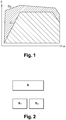
- This service illustrated by the figure 1 , is very consumer of electric energy. It may therefore empty the traction battery quickly. Then, the Energy Management Law (LGE) no longer has the possibility to fully apply, so that the overall consumption of the GMP increases. This situation appears all the more frequently as the capacity of the battery is low.
- LGE Energy Management Law
- a micro-hybrid system for a motor vehicle whose control system comprises means able to define and authorize different modes of operation, including a "recuperative" braking mode of the rotating electrical machine and a mode of assistance in torque of the rotating electric machine.
- the publication EP 1 428 711 A1 describes a control device of a hybrid vehicle, according to which the level of the electric assist torque decreases as a function of the charge level of the battery.
- the present invention aims to control the overall consumption of the powertrain, including the energy expenditure related to torque assistance, according to its energy capacity, so as not to penalize the gain in consumption associated with the hybrid vehicle.
- the electric assist torque available for torque assistance is reduced by a limiting coefficient of between 0 and 1, depending on the amount of energy remaining in a battery energy range reserved for the first time.
- torque assistance which is calculated by integrating the electric power supplied by the electric machine in torque assistance.
- One of the objects of the present invention is thus to control the torque assistance made available to the driver, to limit the impact of this service on the energy optimization of the vehicle.
- the control mechanism introduced in the control dynamically manages the amount of energy that one wishes to allocate to improve the acceleration. It continues to optimize consumption, even if the driver regularly requests performance of the powertrain.
- a hybrid vehicle equipped with a powertrain comprising at least one heat engine and an electric machine, capable of providing together or separately a torque to the wheel
- these two energy sources are placed under the control of management laws (LGE ) optimizing the energy consumption of the vehicle.
- LGE management laws
- a traction battery generally able to recover under form of electrical energy at least a portion of the kinetic energy of the decelerating vehicle, and rechargeable via the engine, feeds the electric machine.
- a hybrid vehicle therefore has at least two actuators capable of providing torque to the wheel: the torque demand of the driver can thus be satisfied by the sum of the torques supplied by the electric machine and the heat engine.
- GMP hybrid powertrain
- LGE energy management law
- the traction battery must always have a sufficient energy reserve to apply the optimal distribution.
- the maximum torque of the powertrain is defined from the maximum torque provided by the engine, to which is added the over-torque provided by the electric machine.
- the curves C 1 , C 2 of the figure 1 respectively show the evolution of the maximum torque of the engine according to its speed ⁇ , and the envelope of maximum torque available to the wheel with the contribution of assistance in electric torque.
- the difference between the two curves C 1 and C 2 represents the electric torque assistance available.
- it is proposed to limit the available electric assist torque by applying a limiting coefficient C, between 0 and 1.
- the electric assistance torque available for the first time. assistance in torque is thus reduced by the limitation coefficient C, according to the remaining amount in a battery power range, which is reserved for assistance in couple.
- the limiting coefficient C is calculated as a function of the remaining energy, in an energy range reserved for the torque assistance.
- the energy stored in the traction battery B is distributed between two energy ranges (B 1 , B 2 ), reserved respectively for the application of the powertrain energy management law outside the electrical assistance in couple, and electrical assistance in couple.
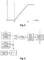
- FIG. 2 The distinction between the two energy ranges is illustrated by the figure 2 : its upper part corresponds to a physical representation of the traction battery B of the vehicle, while its lower part introduces the proposed control mode with the distinction of two fictitious batteries.
- a first battery B 1 whose energy is unreservedly involved in the energy management law in order to reduce the overall consumption of the GMP, and a second battery B 2 , reserved for assistance in couples.
- the coefficient K makes it possible to allocate the energy recovered by the electrical machine in "generator" mode, either in the battery B 1 or in the battery B 2 .
- K 1. All the energy recovered is then allocated to the battery B 2 . The driver can spend the recovered energy, in electric torque assistance.
- K 0. All the energy recovered is allocated to the battery B 1 : it is recharged with the recovered energy, without allocating any energy.
- fictitious battery energy B 2 the driver no longer benefits from electrical assistance during strong acceleration. This prioritizes the reduction of consumption, rather than the performance of the GMP. The driver no longer has all the performance of the electrical assistance since he has already spent all the energy allocated to it.
- the weighting coefficient K defines the order of priority of the energy storage between the battery B 1 and the battery B 2 , in order to improve either the performance or the consumption.
- the difference between the first and the second quantity of energy, weighted by the coefficient K depending on the state of charge of the SOC battery, is integrated.
- the amount of energy I allocated to the energy range B 2 is calculated by integrating the electric power supplied by the electric machine in torque assistance. This power is calculated by difference between the electrical power actually consumed in torque assistance and the electrical power recovered during deceleration or by charging via the heat engine. The recovered electrical power is thus weighted by the weighting coefficient K , calculated as a function of the state of charge of the traction battery.
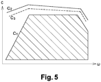
- the value of the integral I corresponding to the reserve of energy reserved for the electric assistance, makes it possible to obtain by cartography, the coefficient of limitation C, limiting the electrical assistance, which is returned in loop on the instruction of electric power available in torque assistance.
- the figure 5 introduced the limitation of the power available for assistance on the figure 1 .
- the physical battery charge state sets the K coefficient to 0.
- the LGE does not have enough energy to optimize power consumption.
- the entirety of the 30 Wh recovered will therefore be allocated to it (battery B 1 ), without allocating energy to the battery B 2 for assistance.
Landscapes
- Engineering & Computer Science (AREA)
- Chemical & Material Sciences (AREA)
- Combustion & Propulsion (AREA)
- Transportation (AREA)
- Mechanical Engineering (AREA)
- Automation & Control Theory (AREA)
- Electric Propulsion And Braking For Vehicles (AREA)
- Hybrid Electric Vehicles (AREA)
Description
La présente invention concerne le domaine technique des véhicules hybrides, et plus précisément celui de leur gestion énergétique.The present invention relates to the technical field of hybrid vehicles, and more specifically that of their energy management.
Elle a pour objet un procédé de limitation du couple d'assistance à l'accélération d'un véhicule hybride équipé d'un groupe motopropulseur comprenant au moins un moteur thermique et une machine de traction, susceptibles de fournir ensemble ou séparément un couple à la roue, sous le contrôle de lois de gestion optimisant la consommation énergétique du véhicule, et d'une batterie de traction apte à récupérer sous forme d'énergie électrique au moins une partie de l'énergie cinétique du véhicule en décélération, et rechargeable via le moteur thermique.It relates to a method for limiting the assisting torque to the acceleration of a hybrid vehicle equipped with a powertrain comprising at least one heat engine and a traction machine, capable of providing together or separately a torque at the wheel, under the control of management laws optimizing the energy consumption of the vehicle, and a traction battery able to recover as electrical energy at least a portion of the kinetic energy of the vehicle in deceleration, and rechargeable via the thermal motor.
Lorsque l'énergie de la batterie d'un véhicule hybride est mise à disposition de toutes les prestations du véhicule, sans gestion de priorité, ni limitation d'usage, l'utilisation du véhicule est limitée par la capacité de stockage des batteries. C'est notamment le cas pour les véhicules non rechargeables sur le réseau électrique, dits « mild-hybrid », dont la capacité énergétique embarquée reste encore assez faible actuellement.When the battery power of a hybrid vehicle is made available to all the vehicle services, without priority management or limitation of use, the use of the vehicle is limited by the storage capacity of the batteries. This is particularly the case for non-rechargeable vehicles on the electricity grid, called "mild-hybrid", whose embedded energy capacity is still quite low at present.
Sans limitation énergétique de sa réponse, le système de contrôle du groupe motopropulseur réalise toujours la demande de couple du conducteur, au risque de vider intégralement la batterie de traction. Lorsque les possibilités de rechargement de la batterie se limitent à la récupération partielle d'énergie cinétique en décélération, elles sont réduites et lentes, même si la batterie est aussi rechargeable par le moteur thermique. Ainsi, un utilisateur relativement "actif", épuisera rapidement la batterie, sans réduire sa consommation, sa conduite « sportive » écartant les gains de consommation inhérents aux véhicules hybrides. Or la réduction de la consommation énergétique est un objectif prioritaire des véhicules hybrides.Without energy limitation of its response, the control system of the powertrain always realizes the torque demand of the driver, at the risk of emptying the traction battery completely. When the recharging possibilities of the battery are limited to the partial recovery of kinetic energy in deceleration, they are reduced and slow, even if the battery is also rechargeable by the engine. Thus, a relatively "active" user, will quickly deplete the battery, without reducing its consumption, its "sporty" driving away the consumption gains inherent in hybrid vehicles. But the reduction of energy consumption is a priority objective of hybrid vehicles.
Une prestation particulièrement appréciée des véhicules hybrides est la possibilité de fournir plus de couple à la roue, avec l'assistance de la machine électrique, que ce que le moteur thermique peut fournir seul. On parle d' « overtorque » ou d'assistance en couple électrique. Lorsque le conducteur accélère à fond, le moteur thermique est assisté par la machine électrique fonctionnant en mode « moteur » pour maximiser le couple fourni à la roue. Cette prestation, illustrée par la
Toutefois, il n'est pas prévu de limiter le couple d'assistance à l'accélération mis à la disposition du conducteur, pour optimiser l'utilisation de la batterie de traction.However, it is not intended to limit the acceleration assistance torque available to the driver, to optimize the use of the traction battery.
La
La présente invention vise à contrôler la consommation globale du groupe motopropulseur, y compris les dépenses énergétiques liées à l'assistance en couple, en fonction de ses capacités énergétiques, de manière à ne pas pénaliser le gain de consommation associé au véhicule hybride.The present invention aims to control the overall consumption of the powertrain, including the energy expenditure related to torque assistance, according to its energy capacity, so as not to penalize the gain in consumption associated with the hybrid vehicle.
Dans ce but, elle propose que le couple d'assistance électrique disponible pour l'assistance en couple est réduit par un coefficient de limitation compris entre 0 et 1, selon la quantité d'énergie restante dans une plage énergétique de la batterie réservée pour l'assistance en couple, qui est calculée en intégrant la puissance électrique fournie par la machine électrique en assistance en couple.For this purpose, it proposes that the electric assist torque available for torque assistance is reduced by a limiting coefficient of between 0 and 1, depending on the amount of energy remaining in a battery energy range reserved for the first time. torque assistance, which is calculated by integrating the electric power supplied by the electric machine in torque assistance.
Un des objets de la présente invention, est ainsi de contrôler l'assistance en couple mise à la disposition du conducteur, pour limiter l'impact de cette prestation sur l'optimisation énergétique du véhicule.One of the objects of the present invention is thus to control the torque assistance made available to the driver, to limit the impact of this service on the energy optimization of the vehicle.
Ces dispositions permettent d'introduire dans la gestion énergétique du véhicule des règles de priorité entre le respect de la demande de couple à la roue du conducteur, et la réduction de la consommation du groupe motopropulseur.These provisions make it possible to introduce in the energy management of the vehicle priority rules between the respect of the torque demand at the driver's wheel, and the reduction of the consumption of the powertrain.
Le mécanisme de contrôle introduit dans la commande gère dynamiquement la quantité d'énergie que l'on souhaite allouer pour améliorer l'accélération. Il continue ainsi à optimiser la consommation, même si le conducteur sollicite régulièrement les performances du groupe motopropulseur.The control mechanism introduced in the control dynamically manages the amount of energy that one wishes to allocate to improve the acceleration. It continues to optimize consumption, even if the driver regularly requests performance of the powertrain.
D'autres caractéristiques et avantages de la présente invention apparaîtront clairement à la lecture de la description suivante d'un mode de réalisation non limitatif de celle-ci, en se reportant aux dessins annexés, sur lesquels :
- la
figure 1 montre l'apport en couple de l'assistance électrique en couple sur le couple maximum du moteur thermique, - la
figure 2 illustre le mode de gestion énergétique proposé, - la
figure 3 illustre le calcul de répartition de l'énergie récupérée sur lequel repose ce mode de gestion, - la
figure 4 est un schéma de calcul de l'intégrale limitant l'assistance en couple électrique, et - la
figure 5 illustre la réduction du couple obtenue par rapport à lafigure 1 .
- the
figure 1 shows the torque contribution of the electrical assistance in torque on the maximum torque of the heat engine, - the
figure 2 illustrates the proposed mode of energy management, - the
figure 3 illustrates the calculation of the distribution of the recovered energy on which this management method is based, - the
figure 4 is a calculation diagram of the integral limiting the assistance in electric torque, and - the
figure 5 illustrates the reduction of the obtained torque compared to thefigure 1 .
Dans un véhicule hybride équipé d'un groupe motopropulseur comprenant au moins un moteur thermique et une machine électrique, susceptibles de fournir ensemble ou séparément un couple à la roue, ces deux sources d'énergie sont placées sous le contrôle de lois de gestion (LGE) optimisant la consommation énergétique du véhicule. Une batterie de traction, généralement apte à récupérer sous forme d'énergie électrique au moins une partie de l'énergie cinétique du véhicule en décélération, et rechargeable via le moteur thermique, alimente la machine électrique.In a hybrid vehicle equipped with a powertrain comprising at least one heat engine and an electric machine, capable of providing together or separately a torque to the wheel, these two energy sources are placed under the control of management laws (LGE ) optimizing the energy consumption of the vehicle. A traction battery, generally able to recover under form of electrical energy at least a portion of the kinetic energy of the decelerating vehicle, and rechargeable via the engine, feeds the electric machine.
Un véhicule hybride dispose donc d'au moins deux actionneurs capables de fournir du couple à la roue : la demande de couple du conducteur peut ainsi être satisfaite par la somme des couples fournis par la machine électrique et le moteur thermique. Comme indiqué ci-dessus, il est possible d'améliorer la consommation globale d'un groupe motopropulseur (GMP) hybride en optimisant la répartition de couple entre les deux actionneurs, grâce à une loi de gestion énergétique (LGE) appropriée. Toutefois, pour que cette loi puisse jouer pleinement son rôle, la batterie de traction doit disposer en permanence d'une réserve d'énergie suffisante pour appliquer la répartition optimale.A hybrid vehicle therefore has at least two actuators capable of providing torque to the wheel: the torque demand of the driver can thus be satisfied by the sum of the torques supplied by the electric machine and the heat engine. As indicated above, it is possible to improve the overall consumption of a hybrid powertrain (GMP) by optimizing the torque distribution between the two actuators, thanks to an appropriate energy management law (LGE). However, for this law to play its full role, the traction battery must always have a sufficient energy reserve to apply the optimal distribution.
Le couple maximum du groupe motopropulseur est défini à partir du couple maximum fourni par le moteur thermique, auquel vient s'ajouter le sur-couple fourni par la machine électrique. Les courbes C1, C2 de la
La distinction entre les deux plages énergétiques est illustrée par la
Pour calculer la quantité d'énergie disponible dans la plage B2, on intègre la puissance déjà fournie par la machine électrique en assistance en couple. La valeur de cette intégrale, nommée I, se calcule de la façon suivante : 
- PElecOVT = max((PGMP - PMAXthermique )*η Elec ;0) est la puissance électrique dissipée en assistance en couple,
- ηElec est un rendement électrique global, comprenant le rendement de la machine électrique, de l'onduleur, et de la batterie, PGMP est la puissance demandé au GMP par le conducteur,
- PMAXthermique est la puissance maximum que peut fournir le moteur thermique,
-

- K est un coefficient de pondération calculé en fonction de l'état de charge de la batterie physique, et
- T est le temps passé en mission.
- P ElecOVT = max (( P GMP - P MAXthermic ) * η Elec ; 0) is the electrical power dissipated in torque assistance,
- η Elec is a total electrical efficiency, including the efficiency of the electrical machine, the inverter, and the battery, P GMP is the power demanded by the driver from the GMP,
- P MAXthermique is the maximum power that can provide the engine,
-
- K is a weighting coefficient calculated according to the state of charge of the physical battery, and
- T is the time spent on a mission.
Le coefficient K permet d'attribuer l'énergie récupérée par la machine électrique en mode « générateur », soit dans la batterie B1, soit dans la batterie B2.The coefficient K makes it possible to allocate the energy recovered by the electrical machine in "generator" mode, either in the battery B 1 or in the battery B 2 .
Lorsque la réserve d'énergie pour l'assistance en couple est pleine, I = 0 [Wh]. Lorsque la réserve d'énergie est vide, I = EMAX [Wh], EMAX étant la quantité d'énergie mise à la disposition du conducteur, c'est-à-dire la capacité de la batterie fictive B2.When the energy reserve for torque assistance is full, I = 0 [Wh]. When the energy reserve is empty, I = E MAX [Wh], E MAX being the amount of energy available to the driver, that is to say the capacity of the dummy battery B 2 .
Si la batterie B1 contient suffisamment d'énergie pour permettre l'optimisation énergétique, alors K = 1. Toute l'énergie récupérée est alors attribuée à la batterie B2. Le conducteur peut dépenser l'énergie récupérée, en assistance en couple électrique.If the battery B 1 contains enough energy to allow energy optimization, then K = 1. All the energy recovered is then allocated to the battery B 2 . The driver can spend the recovered energy, in electric torque assistance.
Si la batterie B1 ne contient pas suffisamment d'énergie pour permettre l'optimisation énergétique, alors K = 0. Toute l'énergie récupérée est attribuée à la batterie B1 : on la recharge avec l'énergie récupérée, sans allouer d'énergie à la batterie fictive B2 : le conducteur ne bénéficie plus de l'assistance électrique lors de fortes accélérations. On donne ainsi la priorité à la réduction de la consommation, plutôt qu'à la performance du GMP. Le conducteur n'a plus toutes les performances de l'assistance électrique dès lors qu'il a déjà dépensé toute l'énergie allouée à celle-ci.If the battery B 1 does not contain enough energy to allow energy optimization, then K = 0. All the energy recovered is allocated to the battery B 1 : it is recharged with the recovered energy, without allocating any energy. fictitious battery energy B 2 : the driver no longer benefits from electrical assistance during strong acceleration. This prioritizes the reduction of consumption, rather than the performance of the GMP. The driver no longer has all the performance of the electrical assistance since he has already spent all the energy allocated to it.
Le coefficient de pondération K définit l'ordre de priorité du stockage d'énergie entre la batterie B1 et la batterie B2, en vue d'améliorer soit la performance, soit la consommation. Le schéma de la
Conformément à la
La valeur de l'intégrale I, correspondant à la réserve d'énergie réservée à l'assistance électrique, permet d'obtenir par cartographie, le coefficient de limitation C, limitant l'assistance électrique, qui est renvoyé en boucle sur la consigne de puissance électrique disponible en assistance en couple.The value of the integral I , corresponding to the reserve of energy reserved for the electric assistance, makes it possible to obtain by cartography, the coefficient of limitation C, limiting the electrical assistance, which is returned in loop on the instruction of electric power available in torque assistance.
La
Comme indiqué plus haut, lorsque l'intégrale I atteint EMAX , le couple électrique en assistance en couple devient nul. L'exemple suivant illustre la mise en oeuvre du procédé à partir de plusieurs exemples.As indicated above, when the integral I reaches E MAX , the electric torque couple becomes zero. The following example illustrates the implementation of the method from several examples.
Dans une première situation, avec une intégrale I (batterie fictive B2) de 30Wh, et une batterie physique B rechargée de 30Wh, on considère son état de charge (SOC) est élevé, K = 1. La loi de gestion de l'énergie (LGE) dispose de suffisamment d'énergie pour optimiser la consommation. Les 30Wh récupérés peuvent être affectés à la batterie fictive B2, pour être dépensés intégralement en assistance.In a first situation, with an integral I (fictitious battery B 2 ) of 30Wh, and a physical battery B recharged by 30Wh, one considers its state of charge (SOC) is high, K = 1. The law of management of the Energy (LGE) has enough energy to optimize consumption. The recovered 30Wh can be assigned to the fictional battery B 2 , to be spent entirely in assistance.
Dans une deuxième situation, avec une même valeur d'intégrale I 30Wh de B2, on a un état de charge de batterie physique faible, plaçant par exemple le coefficient K à 0,33). La LGE ne dispose pas suffisamment d'énergie pour optimiser la consommation. 20Wh des 30Wh de la batterie fictive sont alloués à la LGE (batterie B1) en déchargeant la batterie fictive de seulement 10Wh pour l'assistance (batterie B2).In a second situation, with the same integral value I 30Wh of B 2 , there is a low physical battery charge state, for example placing the coefficient K at 0.33). LGE does not have enough energy to optimize consumption. 20Wh of the fictional battery 30Wh are allocated to the LGE (Battery B 1 ) by discharging the dummy battery of only 10Wh for assistance (Battery B 2 ).
Dans une troisième situation, avec toujours la même valeur d'intégrale de 30Wh, l'état de charge de batterie physique place le coefficient K à la valeur 0. La LGE ne dispose pas suffisamment d'énergie pour optimiser la consommation. L'intégralité des 30 Wh récupérés va donc lui être allouée (batterie B1), sans attribuer d'énergie à la batterie B2 pour l'assistance.In a third situation, with the same 30Wh integral value, the physical battery charge state sets the K coefficient to 0. The LGE does not have enough energy to optimize power consumption. The entirety of the 30 Wh recovered will therefore be allocated to it (battery B 1 ), without allocating energy to the battery B 2 for assistance.
Les avantages de l'invention sont nombreux :
- elle permet de limiter le couple d'assistance électrique mis à la disposition du conducteur pour faire de fortes accélérations, pour ne pas impacter la gestion de l'énergie, en particulier sur les véhicules hybrides avec peu d'énergie embarquée, et
- elle facilite le typage de le la machine électrique entre des cibles de performance ou de consommation.
- it makes it possible to limit the electric assist torque made available to the driver to make strong accelerations, so as not to impact energy management, in particular on hybrid vehicles with little onboard energy, and
- it facilitates the typing of the electric machine between performance targets or consumption.
Claims (8)
- Method for limiting the energy of the torque for electrically boosting the acceleration of a hybrid vehicle equipped with a power train comprising at least one heat engine and one electric machine capable of jointly or separately supplying a torque to the wheel under the control of management laws (LGE) optimizing the energy consumption of the vehicle, and a traction battery (B) capable of recovering at least a part of the kinetic energy of the vehicle in deceleration in the form of electrical energy, and that can be recharged via the heat engine, characterized in that the electrical boosting torque available for torque boost is reduced by a limiting coefficient (C) of between 0 and 1, according to the quantity of the energy remaining within an energy band (B2) of the battery (B), reserved for the torque boost, which is computed by integrating the electrical power supplied by the electrical machine in torque boost mode.
- Energy limiting method according to Claim 1, characterized in that the energy stored in the traction battery is distributed by two energy bands (B1 , B2 ), reserved respectively for the application of the energy management law (LGE) of the power train outwith the electrical torque boost, and with the electrical torque boost.
- Energy limiting method according to Claim 2, characterized in that the electrical power supplied by the electrical machine in torque boost mode is computed by the difference between the electrical power effectively consumed in torque boost mode and the electrical power recovered in deceleration or by recharging via the heat engine.
- Energy limiting method according to Claim 3, characterized in that the electrical power recovered in deceleration or by recharging via the heat engine is weighted by a weighting coefficient (K) computed as a function of the state of charge of the traction battery.
- Energy limiting method according to Claim 4, characterized in that the weighting coefficient (K) is 0 below a first threshold (S1 ) of the percentage of charge (SOC%) of the battery.
- Energy limiting method according to claim 5, characterized in that the coefficient (K) increases from the value 0 to the value 1, between the first threshold (S1 ) and a second threshold (S2) higher than (S1 ).
- Energy limiting method according to one of the preceeding claims, characterized in that the limiting coefficient (C) is obtained by mapping, from the value of the integral (I).
- Energy limiting method according to one of the preceding claims, characterized in that the limiting coefficient (C) of the electrical boost is returned in a loop on the electrical boost torque setpoint.
Applications Claiming Priority (2)
| Application Number | Priority Date | Filing Date | Title |
|---|---|---|---|
| FR1350810A FR3001427B1 (en) | 2013-01-31 | 2013-01-31 | METHOD FOR ENERGETIC LIMITATION OF THE ACCELERATION ASSISTANCE TORQUE OF A HYBRID VEHICLE |
| PCT/FR2014/050171 WO2014118470A1 (en) | 2013-01-31 | 2014-01-30 | Method for reducing the energy of the acceleration-boosting torque of a hybrid vehicle |
Publications (2)
| Publication Number | Publication Date |
|---|---|
| EP2951069A1 EP2951069A1 (en) | 2015-12-09 |
| EP2951069B1 true EP2951069B1 (en) | 2017-01-25 |
Family
ID=48741281
Family Applications (1)
| Application Number | Title | Priority Date | Filing Date |
|---|---|---|---|
| EP14705852.3A Active EP2951069B1 (en) | 2013-01-31 | 2014-01-30 | Method for reducing the energy of the acceleration-boosting torque of a hybrid vehicle |
Country Status (7)
| Country | Link |
|---|---|
| US (1) | US10017171B2 (en) |
| EP (1) | EP2951069B1 (en) |
| JP (1) | JP6444889B2 (en) |
| KR (1) | KR102032215B1 (en) |
| CN (1) | CN104903171B (en) |
| FR (1) | FR3001427B1 (en) |
| WO (1) | WO2014118470A1 (en) |
Families Citing this family (22)
| Publication number | Priority date | Publication date | Assignee | Title |
|---|---|---|---|---|
| FR3001427B1 (en) * | 2013-01-31 | 2016-01-22 | Renault Sas | METHOD FOR ENERGETIC LIMITATION OF THE ACCELERATION ASSISTANCE TORQUE OF A HYBRID VEHICLE |
| US9694684B2 (en) * | 2014-12-03 | 2017-07-04 | Honda Motor Co., Ltd. | Priority based power management system and method for an electric vehicle |
| DE102015006820A1 (en) | 2015-05-22 | 2016-11-24 | Man Truck & Bus Ag | Method for selecting a mode of operation of a hybrid vehicle |
| US9722518B2 (en) * | 2015-12-22 | 2017-08-01 | Faraday & Future Inc. | System and method for improving acceleration performance of an electric vehicle |
| FR3049249B1 (en) * | 2016-03-23 | 2019-06-14 | Renault S.A.S | METHOD OF CONTROLLING A TORQUE OF ELECTRICAL ASSISTANCE |
| DE102018208425B4 (en) | 2018-05-28 | 2026-01-29 | Bayerische Motoren Werke Aktiengesellschaft | Powertrain for a motor vehicle, in particular for a motor car, and methods for operating such a powertrain |
| US10543739B1 (en) * | 2018-07-25 | 2020-01-28 | Fca Us Llc | Mode transition control techniques for an electrically all-wheel drive hybrid vehicle |
| CN112440756B (en) * | 2019-08-29 | 2022-06-17 | 北京新能源汽车股份有限公司 | Constant-speed cruise torque control method, controller, constant-speed cruise system and vehicle |
| FR3104100B1 (en) | 2019-12-06 | 2023-11-24 | Psa Automobiles Sa | VEHICLE WITH TOTAL TORQUE CONTROL PROVIDED BY THE HYBRID GMP IN CASE OF HIGH DEMAND, AND ASSOCIATED CONTROL METHOD |
| CN111775924B (en) * | 2020-07-23 | 2021-05-04 | 厦门金龙联合汽车工业有限公司 | A control method for maximizing braking energy recovery in a hybrid hybrid system |
| US12319160B1 (en) | 2021-08-13 | 2025-06-03 | Oshkosh Defense, Llc | Convoy operations for electrified military vehicles |
| US12060053B1 (en) | 2021-08-13 | 2024-08-13 | Oshkosh Defense, Llc | Military vehicle with control modes |
| US12351028B1 (en) | 2021-08-13 | 2025-07-08 | Oshkosh Defense, Llc | Military vehicle with modular battery units |
| US12083995B1 (en) | 2021-08-13 | 2024-09-10 | Oshkosh Defense, Llc | Power export system for a military vehicle |
| US12311754B1 (en) | 2021-08-13 | 2025-05-27 | Oshkosh Defense, Llc | Power export system for a military vehicle |
| US12358361B1 (en) | 2021-08-13 | 2025-07-15 | Oshkosh Defense, Llc | Electrified military vehicle with electric weaponry support system |
| US11377089B1 (en) | 2021-08-13 | 2022-07-05 | Oshkosh Defense, Llc | Electrified military vehicle |
| US11498409B1 (en) | 2021-08-13 | 2022-11-15 | Oshkosh Defense, Llc | Electrified military vehicle |
| CN115092108B (en) * | 2022-07-31 | 2023-05-12 | 东风商用车有限公司 | Integral architecture auxiliary brake control system |
| CN116142167B (en) * | 2022-12-30 | 2025-02-11 | 东风商用车有限公司 | A vehicle driving mode control method based on virtual dual batteries |
| US20250074392A1 (en) | 2023-09-05 | 2025-03-06 | GM Global Technology Operations LLC | Dynamic acceleration limiting system for electrified vehicles |
| FR3155182A1 (en) * | 2023-11-09 | 2025-05-16 | Stellantis Auto Sas | CONTROLLED DELIVERY OF INCREASED ENGINE TORQUE IN A TWO-POWER LAND VEHICLE |
Family Cites Families (30)
| Publication number | Priority date | Publication date | Assignee | Title |
|---|---|---|---|---|
| JP3425730B2 (en) * | 1998-03-31 | 2003-07-14 | 本田技研工業株式会社 | Control device for hybrid vehicle |
| DE60201615T8 (en) * | 2001-03-14 | 2006-08-24 | Conception Et Development Michelin S.A. | Vehicle with super-capacitor for braking energy recovery |
| JP3827980B2 (en) * | 2001-09-21 | 2006-09-27 | 本田技研工業株式会社 | Control device for hybrid vehicle |
| US6827167B2 (en) * | 2002-03-28 | 2004-12-07 | Ford Global Technologies, Llc | Hybrid electric vehicle torque distribution |
| US7608011B2 (en) * | 2003-01-04 | 2009-10-27 | Ford Global Technologies, Llc | Hydrogen fuelled hybrid powertrain and vehicle |
| US6831429B2 (en) * | 2003-03-10 | 2004-12-14 | Visteon Global Technologies, Inc. | Prediction of available torque and power from battery-powered traction motor |
| JP2004335343A (en) * | 2003-05-09 | 2004-11-25 | Nissan Motor Co Ltd | Control device for fuel cell system |
| JP4013905B2 (en) * | 2003-05-21 | 2007-11-28 | トヨタ自動車株式会社 | POWER OUTPUT DEVICE, ITS CONTROL METHOD, AND AUTOMOBILE |
| EP1695883B1 (en) * | 2003-12-01 | 2013-09-04 | Nissan Motor Company Limited | Braking device for vehicle |
| JP4259403B2 (en) * | 2004-06-04 | 2009-04-30 | トヨタ自動車株式会社 | POWER OUTPUT DEVICE, HYBRID VEHICLE HAVING THE SAME, AND METHOD FOR CONTROLLING POWER OUTPUT DEVICE |
| CA2623398A1 (en) * | 2005-09-23 | 2007-04-05 | Afs Trinity Power Corporation | Method and apparatus for power electronics and control of plug-in hybrid propulsion with fast energy storage |
| US7640744B2 (en) * | 2005-12-02 | 2010-01-05 | Ford Global Technologies, Llc | Method for compensating compressor lag of a hybrid powertrain |
| JP4685655B2 (en) * | 2006-02-15 | 2011-05-18 | トヨタ自動車株式会社 | Control device for electric vehicle |
| US7581528B2 (en) * | 2006-03-17 | 2009-09-01 | Ford Global Technologies, Llc | Control strategy for engine employng multiple injection types |
| DE102006016133A1 (en) * | 2006-04-06 | 2007-10-11 | Robert Bosch Gmbh | Mode and torque coordination for hybrid vehicle drives |
| US8140204B2 (en) * | 2007-12-10 | 2012-03-20 | Ford Global Technologies, Llc | Charge depleting energy management strategy for plug-in hybrid electric vehicles |
| JP5029915B2 (en) * | 2008-07-31 | 2012-09-19 | アイシン・エィ・ダブリュ株式会社 | Rotating electrical machine control system and vehicle drive system |
| US8337359B2 (en) * | 2008-08-27 | 2012-12-25 | EcoMotors International | Hybrid engine system |
| JP4805329B2 (en) * | 2008-11-07 | 2011-11-02 | ファナック株式会社 | Control device for calculating power consumption of industrial machinery |
| DE102008054699A1 (en) * | 2008-12-16 | 2010-06-24 | Robert Bosch Gmbh | Method for reducing a drive power of a vehicle drive |
| JP5177552B2 (en) * | 2008-12-26 | 2013-04-03 | アイシン・エィ・ダブリュ株式会社 | Control device |
| US8744716B2 (en) * | 2009-12-16 | 2014-06-03 | GM Global Technology Operations LLC | Speed control systems and methods for internal combustion engines |
| WO2011079246A2 (en) * | 2009-12-23 | 2011-06-30 | Indiana University Research & Technology Corporation | Central wind turbine power generation |
| US8412396B2 (en) * | 2010-06-07 | 2013-04-02 | GM Global Technology Operations LLC | Electric launch of a hybrid vehicle having a belt alternator starter and a dual clutch transmission |
| GB2486177A (en) * | 2010-12-02 | 2012-06-13 | Land Rover Uk Ltd | Traction control method that allows for processing time delays |
| CN103283103B (en) * | 2010-12-24 | 2015-11-25 | 丰田自动车株式会社 | Power-supply system, carry its vehicle and the control method of electrical storage device |
| CN102556056A (en) * | 2012-01-16 | 2012-07-11 | 河南科技大学 | Double fuzzy energy control management system of hybrid power automobile |
| JP5966376B2 (en) * | 2012-01-20 | 2016-08-10 | トヨタ自動車株式会社 | Control device for hybrid vehicle |
| FR3001427B1 (en) * | 2013-01-31 | 2016-01-22 | Renault Sas | METHOD FOR ENERGETIC LIMITATION OF THE ACCELERATION ASSISTANCE TORQUE OF A HYBRID VEHICLE |
| US9216707B2 (en) * | 2014-03-13 | 2015-12-22 | GM Global Technology Operations LLC | Motor generator unit with multiplexed output |
-
2013
- 2013-01-31 FR FR1350810A patent/FR3001427B1/en not_active Expired - Fee Related
-
2014
- 2014-01-30 WO PCT/FR2014/050171 patent/WO2014118470A1/en not_active Ceased
- 2014-01-30 EP EP14705852.3A patent/EP2951069B1/en active Active
- 2014-01-30 CN CN201480004130.0A patent/CN104903171B/en active Active
- 2014-01-30 JP JP2015555771A patent/JP6444889B2/en active Active
- 2014-01-30 US US14/759,021 patent/US10017171B2/en active Active
- 2014-01-30 KR KR1020157018940A patent/KR102032215B1/en active Active
Also Published As
| Publication number | Publication date |
|---|---|
| KR20150115735A (en) | 2015-10-14 |
| JP2016508468A (en) | 2016-03-22 |
| US10017171B2 (en) | 2018-07-10 |
| KR102032215B1 (en) | 2019-10-15 |
| WO2014118470A1 (en) | 2014-08-07 |
| JP6444889B2 (en) | 2018-12-26 |
| US20150360678A1 (en) | 2015-12-17 |
| CN104903171A (en) | 2015-09-09 |
| FR3001427B1 (en) | 2016-01-22 |
| CN104903171B (en) | 2017-10-10 |
| EP2951069A1 (en) | 2015-12-09 |
| FR3001427A1 (en) | 2014-08-01 |
Similar Documents
| Publication | Publication Date | Title |
|---|---|---|
| EP2951069B1 (en) | Method for reducing the energy of the acceleration-boosting torque of a hybrid vehicle | |
| CN101460726B (en) | Hybrid vehicle control device and hybrid vehicle | |
| JP6596480B2 (en) | Control device for hybrid vehicle | |
| EP2429854B1 (en) | System for controlling the torque applied to the wheels of a vehicle provided with at least one electric motor | |
| EP2885146B1 (en) | Method for limiting the torque of an electric machine of a hybrid vehicle, in case of a high torque request | |
| US9002561B2 (en) | Drive control apparatus and drive control method for hybrid vehicles and hybrid vehicle | |
| JPWO2011125865A1 (en) | Control device for hybrid vehicle | |
| US9260106B2 (en) | Method and device for controlling an internal combustion engine | |
| WO2022117857A1 (en) | Method and device for controlling an electric drive system for an electric vehicle | |
| EP2079623A2 (en) | Method for controlling the operation of a hybrid vehicle | |
| De Jager et al. | An adaptive sub-optimal energy management strategy for hybrid drive-trains | |
| FR3049249B1 (en) | METHOD OF CONTROLLING A TORQUE OF ELECTRICAL ASSISTANCE | |
| EP2271532B1 (en) | Method for acceleration control of a hybrid vehicle | |
| FR3015411A1 (en) | TORQUE SETTING CALCULATION METHOD FOR AN ELECTRIC MACHINE COUPLED TO A THERMAL MOTOR OF A HYBRID VEHICLE | |
| JP2010016956A (en) | Device and method for managing electric storage device | |
| EP3044060B1 (en) | Method for a hybrid or electric vehicle for regulating the distance with a preceding vehicle | |
| JP6149720B2 (en) | Hybrid vehicle | |
| EP2758292B1 (en) | Method for monitoring the electric energy supplied by hybrid vehicle batteries | |
| FR3078204A1 (en) | MANAGEMENT OF ELECTRICAL ENERGY IN A HYBRID MOTOR VEHICLE | |
| JP6527062B2 (en) | Charge control device | |
| FR2989839A1 (en) | Method for optimizing charging of batteries during storage in e.g. electric car, involves performing refilling of batteries if factor for current level is higher and deferring recharging of batteries if factor for load level is lower | |
| JP2019119395A (en) | Control device |
Legal Events
| Date | Code | Title | Description |
|---|---|---|---|
| PUAI | Public reference made under article 153(3) epc to a published international application that has entered the european phase |
Free format text: ORIGINAL CODE: 0009012 |
|
| 17P | Request for examination filed |
Effective date: 20150623 |
|
| AK | Designated contracting states |
Kind code of ref document: A1 Designated state(s): AL AT BE BG CH CY CZ DE DK EE ES FI FR GB GR HR HU IE IS IT LI LT LU LV MC MK MT NL NO PL PT RO RS SE SI SK SM TR |
|
| AX | Request for extension of the european patent |
Extension state: BA ME |
|
| DAX | Request for extension of the european patent (deleted) | ||
| REG | Reference to a national code |
Ref country code: DE Ref legal event code: R079 Ref document number: 602014006357 Country of ref document: DE Free format text: PREVIOUS MAIN CLASS: B60W0020000000 Ipc: B60W0020130000 |
|
| RIC1 | Information provided on ipc code assigned before grant |
Ipc: B60W 10/26 20060101ALI20160622BHEP Ipc: B60W 20/13 20160101AFI20160622BHEP Ipc: B60W 20/14 20160101ALI20160622BHEP Ipc: B60W 10/06 20060101ALI20160622BHEP Ipc: B60W 20/19 20160101ALI20160622BHEP Ipc: B60W 10/08 20060101ALI20160622BHEP |
|
| GRAP | Despatch of communication of intention to grant a patent |
Free format text: ORIGINAL CODE: EPIDOSNIGR1 |
|
| INTG | Intention to grant announced |
Effective date: 20160812 |
|
| RIN1 | Information on inventor provided before grant (corrected) |
Inventor name: LE ROY, LOIC Inventor name: RUEL, JEAN-MARTIN |
|
| GRAS | Grant fee paid |
Free format text: ORIGINAL CODE: EPIDOSNIGR3 |
|
| STAA | Information on the status of an ep patent application or granted ep patent |
Free format text: STATUS: GRANT OF PATENT IS INTENDED |
|
| GRAA | (expected) grant |
Free format text: ORIGINAL CODE: 0009210 |
|
| STAA | Information on the status of an ep patent application or granted ep patent |
Free format text: STATUS: THE PATENT HAS BEEN GRANTED |
|
| AK | Designated contracting states |
Kind code of ref document: B1 Designated state(s): AL AT BE BG CH CY CZ DE DK EE ES FI FR GB GR HR HU IE IS IT LI LT LU LV MC MK MT NL NO PL PT RO RS SE SI SK SM TR |
|
| REG | Reference to a national code |
Ref country code: GB Ref legal event code: FG4D Free format text: NOT ENGLISH |
|
| REG | Reference to a national code |
Ref country code: CH Ref legal event code: EP Ref country code: FR Ref legal event code: PLFP Year of fee payment: 4 |
|
| REG | Reference to a national code |
Ref country code: AT Ref legal event code: REF Ref document number: 863916 Country of ref document: AT Kind code of ref document: T Effective date: 20170215 |
|
| REG | Reference to a national code |
Ref country code: IE Ref legal event code: FG4D Free format text: LANGUAGE OF EP DOCUMENT: FRENCH |
|
| REG | Reference to a national code |
Ref country code: DE Ref legal event code: R096 Ref document number: 602014006357 Country of ref document: DE |
|
| REG | Reference to a national code |
Ref country code: LT Ref legal event code: MG4D |
|
| PG25 | Lapsed in a contracting state [announced via postgrant information from national office to epo] |
Ref country code: BE Free format text: LAPSE BECAUSE OF NON-PAYMENT OF DUE FEES Effective date: 20170131 |
|
| REG | Reference to a national code |
Ref country code: NL Ref legal event code: MP Effective date: 20170125 |
|
| REG | Reference to a national code |
Ref country code: AT Ref legal event code: MK05 Ref document number: 863916 Country of ref document: AT Kind code of ref document: T Effective date: 20170125 |
|
| PG25 | Lapsed in a contracting state [announced via postgrant information from national office to epo] |
Ref country code: NL Free format text: LAPSE BECAUSE OF FAILURE TO SUBMIT A TRANSLATION OF THE DESCRIPTION OR TO PAY THE FEE WITHIN THE PRESCRIBED TIME-LIMIT Effective date: 20170125 |
|
| PG25 | Lapsed in a contracting state [announced via postgrant information from national office to epo] |
Ref country code: LT Free format text: LAPSE BECAUSE OF FAILURE TO SUBMIT A TRANSLATION OF THE DESCRIPTION OR TO PAY THE FEE WITHIN THE PRESCRIBED TIME-LIMIT Effective date: 20170125 Ref country code: GR Free format text: LAPSE BECAUSE OF FAILURE TO SUBMIT A TRANSLATION OF THE DESCRIPTION OR TO PAY THE FEE WITHIN THE PRESCRIBED TIME-LIMIT Effective date: 20170426 Ref country code: FI Free format text: LAPSE BECAUSE OF FAILURE TO SUBMIT A TRANSLATION OF THE DESCRIPTION OR TO PAY THE FEE WITHIN THE PRESCRIBED TIME-LIMIT Effective date: 20170125 Ref country code: HR Free format text: LAPSE BECAUSE OF FAILURE TO SUBMIT A TRANSLATION OF THE DESCRIPTION OR TO PAY THE FEE WITHIN THE PRESCRIBED TIME-LIMIT Effective date: 20170125 Ref country code: NO Free format text: LAPSE BECAUSE OF FAILURE TO SUBMIT A TRANSLATION OF THE DESCRIPTION OR TO PAY THE FEE WITHIN THE PRESCRIBED TIME-LIMIT Effective date: 20170425 Ref country code: IS Free format text: LAPSE BECAUSE OF FAILURE TO SUBMIT A TRANSLATION OF THE DESCRIPTION OR TO PAY THE FEE WITHIN THE PRESCRIBED TIME-LIMIT Effective date: 20170525 |
|
| PG25 | Lapsed in a contracting state [announced via postgrant information from national office to epo] |
Ref country code: PL Free format text: LAPSE BECAUSE OF FAILURE TO SUBMIT A TRANSLATION OF THE DESCRIPTION OR TO PAY THE FEE WITHIN THE PRESCRIBED TIME-LIMIT Effective date: 20170125 Ref country code: ES Free format text: LAPSE BECAUSE OF FAILURE TO SUBMIT A TRANSLATION OF THE DESCRIPTION OR TO PAY THE FEE WITHIN THE PRESCRIBED TIME-LIMIT Effective date: 20170125 Ref country code: BG Free format text: LAPSE BECAUSE OF FAILURE TO SUBMIT A TRANSLATION OF THE DESCRIPTION OR TO PAY THE FEE WITHIN THE PRESCRIBED TIME-LIMIT Effective date: 20170425 Ref country code: SE Free format text: LAPSE BECAUSE OF FAILURE TO SUBMIT A TRANSLATION OF THE DESCRIPTION OR TO PAY THE FEE WITHIN THE PRESCRIBED TIME-LIMIT Effective date: 20170125 Ref country code: PT Free format text: LAPSE BECAUSE OF FAILURE TO SUBMIT A TRANSLATION OF THE DESCRIPTION OR TO PAY THE FEE WITHIN THE PRESCRIBED TIME-LIMIT Effective date: 20170525 Ref country code: AT Free format text: LAPSE BECAUSE OF FAILURE TO SUBMIT A TRANSLATION OF THE DESCRIPTION OR TO PAY THE FEE WITHIN THE PRESCRIBED TIME-LIMIT Effective date: 20170125 Ref country code: RS Free format text: LAPSE BECAUSE OF FAILURE TO SUBMIT A TRANSLATION OF THE DESCRIPTION OR TO PAY THE FEE WITHIN THE PRESCRIBED TIME-LIMIT Effective date: 20170125 Ref country code: LV Free format text: LAPSE BECAUSE OF FAILURE TO SUBMIT A TRANSLATION OF THE DESCRIPTION OR TO PAY THE FEE WITHIN THE PRESCRIBED TIME-LIMIT Effective date: 20170125 |
|
| REG | Reference to a national code |
Ref country code: CH Ref legal event code: PL |
|
| REG | Reference to a national code |
Ref country code: DE Ref legal event code: R097 Ref document number: 602014006357 Country of ref document: DE |
|
| PG25 | Lapsed in a contracting state [announced via postgrant information from national office to epo] |
Ref country code: RO Free format text: LAPSE BECAUSE OF FAILURE TO SUBMIT A TRANSLATION OF THE DESCRIPTION OR TO PAY THE FEE WITHIN THE PRESCRIBED TIME-LIMIT Effective date: 20170125 Ref country code: IT Free format text: LAPSE BECAUSE OF FAILURE TO SUBMIT A TRANSLATION OF THE DESCRIPTION OR TO PAY THE FEE WITHIN THE PRESCRIBED TIME-LIMIT Effective date: 20170125 Ref country code: SK Free format text: LAPSE BECAUSE OF FAILURE TO SUBMIT A TRANSLATION OF THE DESCRIPTION OR TO PAY THE FEE WITHIN THE PRESCRIBED TIME-LIMIT Effective date: 20170125 Ref country code: CZ Free format text: LAPSE BECAUSE OF FAILURE TO SUBMIT A TRANSLATION OF THE DESCRIPTION OR TO PAY THE FEE WITHIN THE PRESCRIBED TIME-LIMIT Effective date: 20170125 Ref country code: LI Free format text: LAPSE BECAUSE OF NON-PAYMENT OF DUE FEES Effective date: 20170131 Ref country code: EE Free format text: LAPSE BECAUSE OF FAILURE TO SUBMIT A TRANSLATION OF THE DESCRIPTION OR TO PAY THE FEE WITHIN THE PRESCRIBED TIME-LIMIT Effective date: 20170125 Ref country code: CH Free format text: LAPSE BECAUSE OF NON-PAYMENT OF DUE FEES Effective date: 20170131 |
|
| REG | Reference to a national code |
Ref country code: IE Ref legal event code: MM4A |
|
| PG25 | Lapsed in a contracting state [announced via postgrant information from national office to epo] |
Ref country code: SM Free format text: LAPSE BECAUSE OF FAILURE TO SUBMIT A TRANSLATION OF THE DESCRIPTION OR TO PAY THE FEE WITHIN THE PRESCRIBED TIME-LIMIT Effective date: 20170125 Ref country code: MC Free format text: LAPSE BECAUSE OF FAILURE TO SUBMIT A TRANSLATION OF THE DESCRIPTION OR TO PAY THE FEE WITHIN THE PRESCRIBED TIME-LIMIT Effective date: 20170125 Ref country code: LU Free format text: LAPSE BECAUSE OF NON-PAYMENT OF DUE FEES Effective date: 20170130 Ref country code: DK Free format text: LAPSE BECAUSE OF FAILURE TO SUBMIT A TRANSLATION OF THE DESCRIPTION OR TO PAY THE FEE WITHIN THE PRESCRIBED TIME-LIMIT Effective date: 20170125 |
|
| PLBE | No opposition filed within time limit |
Free format text: ORIGINAL CODE: 0009261 |
|
| STAA | Information on the status of an ep patent application or granted ep patent |
Free format text: STATUS: NO OPPOSITION FILED WITHIN TIME LIMIT |
|
| 26N | No opposition filed |
Effective date: 20171026 |
|
| REG | Reference to a national code |
Ref country code: FR Ref legal event code: PLFP Year of fee payment: 5 |
|
| REG | Reference to a national code |
Ref country code: BE Ref legal event code: MM Effective date: 20170131 |
|
| PG25 | Lapsed in a contracting state [announced via postgrant information from national office to epo] |
Ref country code: IE Free format text: LAPSE BECAUSE OF NON-PAYMENT OF DUE FEES Effective date: 20170130 Ref country code: SI Free format text: LAPSE BECAUSE OF FAILURE TO SUBMIT A TRANSLATION OF THE DESCRIPTION OR TO PAY THE FEE WITHIN THE PRESCRIBED TIME-LIMIT Effective date: 20170125 |
|
| PG25 | Lapsed in a contracting state [announced via postgrant information from national office to epo] |
Ref country code: MT Free format text: LAPSE BECAUSE OF FAILURE TO SUBMIT A TRANSLATION OF THE DESCRIPTION OR TO PAY THE FEE WITHIN THE PRESCRIBED TIME-LIMIT Effective date: 20170125 |
|
| PG25 | Lapsed in a contracting state [announced via postgrant information from national office to epo] |
Ref country code: HU Free format text: LAPSE BECAUSE OF FAILURE TO SUBMIT A TRANSLATION OF THE DESCRIPTION OR TO PAY THE FEE WITHIN THE PRESCRIBED TIME-LIMIT; INVALID AB INITIO Effective date: 20140130 |
|
| PG25 | Lapsed in a contracting state [announced via postgrant information from national office to epo] |
Ref country code: CY Free format text: LAPSE BECAUSE OF FAILURE TO SUBMIT A TRANSLATION OF THE DESCRIPTION OR TO PAY THE FEE WITHIN THE PRESCRIBED TIME-LIMIT Effective date: 20170125 |
|
| PG25 | Lapsed in a contracting state [announced via postgrant information from national office to epo] |
Ref country code: MK Free format text: LAPSE BECAUSE OF FAILURE TO SUBMIT A TRANSLATION OF THE DESCRIPTION OR TO PAY THE FEE WITHIN THE PRESCRIBED TIME-LIMIT Effective date: 20170125 |
|
| PG25 | Lapsed in a contracting state [announced via postgrant information from national office to epo] |
Ref country code: TR Free format text: LAPSE BECAUSE OF FAILURE TO SUBMIT A TRANSLATION OF THE DESCRIPTION OR TO PAY THE FEE WITHIN THE PRESCRIBED TIME-LIMIT Effective date: 20170125 |
|
| PG25 | Lapsed in a contracting state [announced via postgrant information from national office to epo] |
Ref country code: AL Free format text: LAPSE BECAUSE OF FAILURE TO SUBMIT A TRANSLATION OF THE DESCRIPTION OR TO PAY THE FEE WITHIN THE PRESCRIBED TIME-LIMIT Effective date: 20170125 |
|
| P01 | Opt-out of the competence of the unified patent court (upc) registered |
Effective date: 20230608 |
|
| REG | Reference to a national code |
Ref country code: GB Ref legal event code: 732E Free format text: REGISTERED BETWEEN 20231228 AND 20240103 |
|
| REG | Reference to a national code |
Ref country code: DE Ref legal event code: R081 Ref document number: 602014006357 Country of ref document: DE Owner name: NEW H POWERTRAIN HOLDING, S.L.U., ES Free format text: FORMER OWNER: RENAULT S.A.S., BOULOGNE-BILLANCOURT, FR |
|
| PGFP | Annual fee paid to national office [announced via postgrant information from national office to epo] |
Ref country code: DE Payment date: 20250121 Year of fee payment: 12 |
|
| PGFP | Annual fee paid to national office [announced via postgrant information from national office to epo] |
Ref country code: FR Payment date: 20250127 Year of fee payment: 12 |
|
| PGFP | Annual fee paid to national office [announced via postgrant information from national office to epo] |
Ref country code: GB Payment date: 20250128 Year of fee payment: 12 |