EP2950876B1 - Improved medical connector - Google Patents
Improved medical connector Download PDFInfo
- Publication number
- EP2950876B1 EP2950876B1 EP14704617.1A EP14704617A EP2950876B1 EP 2950876 B1 EP2950876 B1 EP 2950876B1 EP 14704617 A EP14704617 A EP 14704617A EP 2950876 B1 EP2950876 B1 EP 2950876B1
- Authority
- EP
- European Patent Office
- Prior art keywords
- needle
- seal
- cavity
- connector
- hole
- Prior art date
- Legal status (The legal status is an assumption and is not a legal conclusion. Google has not performed a legal analysis and makes no representation as to the accuracy of the status listed.)
- Active
Links
- 238000011144 upstream manufacturing Methods 0.000 claims description 46
- 239000011324 bead Substances 0.000 claims description 31
- 230000002093 peripheral effect Effects 0.000 claims description 30
- 239000012530 fluid Substances 0.000 claims description 29
- 230000000295 complement effect Effects 0.000 claims description 11
- 239000007788 liquid Substances 0.000 description 28
- 230000000694 effects Effects 0.000 description 9
- 230000006835 compression Effects 0.000 description 7
- 238000007906 compression Methods 0.000 description 7
- 239000008280 blood Substances 0.000 description 4
- 210000004369 blood Anatomy 0.000 description 4
- 230000014509 gene expression Effects 0.000 description 3
- 239000000463 material Substances 0.000 description 3
- 230000015572 biosynthetic process Effects 0.000 description 2
- 238000007790 scraping Methods 0.000 description 2
- LFQSCWFLJHTTHZ-UHFFFAOYSA-N Ethanol Chemical compound CCO LFQSCWFLJHTTHZ-UHFFFAOYSA-N 0.000 description 1
- 238000004026 adhesive bonding Methods 0.000 description 1
- 230000005540 biological transmission Effects 0.000 description 1
- 239000002131 composite material Substances 0.000 description 1
- 238000011109 contamination Methods 0.000 description 1
- 229940082150 encore Drugs 0.000 description 1
- 238000004519 manufacturing process Methods 0.000 description 1
- 230000007935 neutral effect Effects 0.000 description 1
- 239000002504 physiological saline solution Substances 0.000 description 1
- 229920001296 polysiloxane Polymers 0.000 description 1
- 210000003462 vein Anatomy 0.000 description 1
Images

Classifications
-
- A—HUMAN NECESSITIES
- A61—MEDICAL OR VETERINARY SCIENCE; HYGIENE
- A61M—DEVICES FOR INTRODUCING MEDIA INTO, OR ONTO, THE BODY; DEVICES FOR TRANSDUCING BODY MEDIA OR FOR TAKING MEDIA FROM THE BODY; DEVICES FOR PRODUCING OR ENDING SLEEP OR STUPOR
- A61M39/00—Tubes, tube connectors, tube couplings, valves, access sites or the like, specially adapted for medical use
- A61M39/10—Tube connectors; Tube couplings
-
- A—HUMAN NECESSITIES
- A61—MEDICAL OR VETERINARY SCIENCE; HYGIENE
- A61M—DEVICES FOR INTRODUCING MEDIA INTO, OR ONTO, THE BODY; DEVICES FOR TRANSDUCING BODY MEDIA OR FOR TAKING MEDIA FROM THE BODY; DEVICES FOR PRODUCING OR ENDING SLEEP OR STUPOR
- A61M39/00—Tubes, tube connectors, tube couplings, valves, access sites or the like, specially adapted for medical use
- A61M39/22—Valves or arrangement of valves
- A61M39/26—Valves closing automatically on disconnecting the line and opening on reconnection thereof
Definitions
- the present invention relates to the technical sector of connectors for medical use, and more particularly relates to a connector for medical use of the type comprising a chamber integral with a connector provided with a needle for dispensing a fluid, the needle being sheathed in an elastic joint.
- this connector has a chamber integral with its base with a connector constituting the upstream end of the connector itself.
- the free end of the chamber, opposite the base, is intended to receive, by friction, the tip of a connector of the male luer type.
- the passage of the liquid between the catheter connected to the upstream end of the connector and the end of the male luer is ensured by means of a needle secured to the body of the connector. The needle extends into the chamber and opens into the terminal end of said chamber.
- the needle is sheathed and held in the imprint of an elastic seal having, in the thickness of its free terminal end, a slot or equivalent allowing the passage of the needle when the elastic seal is compressed in the connected position of the connector .
- this type of connector is used both for taking blood samples but especially for injecting parenteral bags.
- the catheter is cleaned with physiological saline or alcohol.
- the document WO2008 / 052140 describes a connector, the needle of which is provided with two longitudinal slots in which, when not connected, protuberances arranged on the internal wall of the elastic joint are inserted.
- protuberances are formed only over only part of the circumference of the seal, the liquid coming from the slots when these are uncovered, flows on either side of the slots, both in the upstream direction as downstream.
- all the available volume existing between the barrel of the needle and the internal wall of the elastic seal is filled with liquid.
- a residual volume of liquid between the strands on either side of the lateral orifices will remain in the disconnected position. This stagnant liquid cannot be purged since the orifices are blocked after disconnection. There follows an obvious risk of contamination.
- the object of the invention is to remedy the aforementioned drawbacks by proposing a connector for medical use which does not cause any undesirable rise in liquid when it is disconnected and which leaves as little residual volume as possible, advantageously no residual volume.
- the objective of the invention is to provide a connector capable of generating, when it is disconnected, a pressure making it possible to return a volume of liquid in the needle at least equal to the volume of additional liquid drawn from the catheter . More generally, either the volume returned corresponds to the volume sucked (we speak of a neutral valve). In this case, the volume of the catheter is exclusively filled with the injected liquid. Either the volume returned is slightly greater than the volume aspirated (we speak of a positive valve). In the latter case, a small volume of the injected liquid enters the patient's vein.
- a connector for medical use comprising a connection integral with a chamber, the connection being provided in its center with a needle extending in said chamber and opening out at its terminal end, which has a section capable of receiving, by friction, a connector of the male luer type for the circulation of a fluid, the needle having a distal part provided with at least one lateral orifice opening out and being contained in the imprint of a elastic seal having, in the thickness of its free end, a slot or the like, the elastic seal being compressed during connection to uncover the distal part of the needle and ensuring the transfer of fluid, and released offline.
- distal end of the needle denotes the part of the needle not covered by the elastic seal in the connected position of the connector.
- connection means that there is a passage of liquid between the male luer and the needle.
- the expression “the elastic seal in the compressed state forms with the needle, immediately upstream of the upper level of the additional orifice and only over a portion of the distance separating said orifice from the upstream end of the seal” expresses the fact that the sealed cavity does not extend, upstream of the upper level of the additional orifice, over the entire length of the needle but only over part. This means that the orifice is contained in the sealed cavity in the connected position and that the liquid cannot flow between the wall of the elastic seal and the barrel of the needle on either side of the cavity thus delimited.
- the cavity is present in the connected position of the connector, regardless of whether or not it exists before connection.
- the cavity When the cavity does not exist before connection, it forms immediately upstream of the upper level of said additional orifice, the volume of the cavity increasing as the elastic seal is compressed over only a portion of the length of this one.
- the cavity exists before connection, it moves along the needle, under the effect of the compression of the elastic seal, in the upstream direction of the device.
- the elastic seal undergoes compression under the effect of the force exerted by the terminal end of the male luer type connector coming to be inserted in the terminal end of the chamber.
- This compression has the effect of releasing the additional orifice and forming immediately upstream of its upper level (in the direction of flow), a sealed dead volume between the internal wall of the seal and the wall of the needle on only part of the distance from the additional hole to the base of the seal or needle.
- Part of the fluid circulating in the needle is sucked through the additional orifice into the cavity thus formed.
- the seal gradually returns to its initial position by spring effect.
- the part of the elastic seal downstream of the additional orifices rises along the needle at the time of disconnection more quickly than the part upstream.
- the reintroduction of the liquid into the barrel of the needle through the additional orifice creates resistance and necessarily slows the rise of the seal.
- the sealed cavity contains practically no more liquid within the tolerances close to the manufacture of the elastic seal.
- the additional orifice is formed on the barrel of the needle, advantageously in its middle part.
- the cavity is formed only at the time of connection, by compression of the elastic seal.
- the portion of the seal in contact with the needle downstream of the orifice undergoes an upstream translational movement. While freeing up the additional orifice, a space is created between the wall of the seal and the barrel of the needle which is at this level, of shape which is not complementary with the shape of the internal wall of the elastic seal.
- the needle and the internal wall of the seal are of complementary shape over only part of the distance separating said orifice from the distal end of the needle.
- the wall of the part of the seal of shape complementary to that of the needle is more rigid than that of the rest of the seal. Consequently, the part of the elastic seal in contact with the needle undergoes a translational movement under the effect of the force exerted by the connector at the time of connection, causing the formation of the cavity upstream of the additional orifice.
- the needle immediately upstream of the additional orifice, the needle successively has a first section of cylindrical external section then a second conical section of external section increasing in the direction of the base of the needle.
- the external section of the second section at its birth is greater than the external section of the first section so as to form a peripheral support and end-of-travel rim of the peripheral bead capable of closing the at least one additional orifice in the compressed position. elastic seal, thus guaranteeing the tightness of the chamber.
- the elastic seal has a preformed cavity before connection.
- the internal wall of the joint immediately downstream of the peripheral bead, has a tubular section delimited downstream by a second peripheral bead maintained in close contact with the needle in the released position of the joint.
- the preformed cavity performs a translational movement upstream relative to the needle.
- the cavity fills with fluid. Due to the presence of the peripheral rim, the wall of the cavity is in close contact with said rim so that the cavity formed below the upper level of the additional orifice is filled with liquid and remains sealed.
- the peripheral rim serves as a support and end of travel for the second peripheral bead in the compressed position of the elastic seal.
- the wall of the tubular section is more rigid than that of the rest of the joint.
- the section of the tubular joint is grooved.
- the wall of the joint upstream and downstream of the cavity is in the form of a succession of beads giving the parts of the joint downstream and upstream of the cavity an identical rigidity.
- the number of additional orifices is not limited provided that their positioning is compatible with the functioning of the connector.
- the additional orifices are 2 in number and positioned opposite one another.
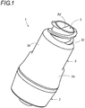
- FIG 1 representing a connector (1) for medical use according to the invention, it comprises a connector (2) integral with a chamber (3) as well as a ring (4) / elastic joint (5) assembly.
- the connector (2) is in the form of a composite part associating the body of the connector (2) proper and a needle (6).
- the chamber (3) includes a proximal compartment (3a), a central compartment (3b) and a distal compartment (3c).
- the distal compartment (3c) of the chamber (3) has a section capable of receiving, by friction, a connector (7) of the male luer type.
- the proximal compartment (3a) of the chamber (3) cooperates with the connector (2), intended to receive a catheter connecting the patient and in which a fluid circulates.
- the body of the connector (2) comprises a recess (2a), provided on its internal face with a screw pitch intended to cooperate with a corresponding screw pitch of a catheter or other female luer connector in which can circulate a fluid.
- the body of the connector (2) is provided in its center with a needle (6) extending from the proximal compartment (3a) to the distal compartment (3c).
- the needle (6) proper is provided, near its free end, itself closed, with two lateral upper orifices (6a) through which the fluid flows when its distal part is uncovered, that is to say - say in the connected position.
- the needle (6) is in fact sheathed over its entire length in the imprint of an elastic seal (5) whose end part is encircled by a ring (4).
- the distal end at least of the needle (6) has a substantially conical shape so as to favor its release under the effect of the push exerted by the connector (7) male luer type on the ring assembly (4) / elastic seal (5).
- the needle (6) comprises according to the invention, two additional lateral lower orifices (6b), formed in its middle part. They are diametrically opposed to each other.
- the needle has downstream of the orifices (6b) a conical section (6c). Upstream of the orifices (6b), the needle successively has a first section (6d) of cylindrical external section and then a second section (6e) of conical external section increasing towards the base of the needle. At its birth, the second section has a diameter greater than that of the first section so as to form a peripheral rim (6f).
- the elastic seal (5) is made of silicone and is in the form of a tube of external section of generally conical shape, intended to extend in the chamber (3) from the body of the fitting (2) to the free end of the terminal compartment (3c) of the chamber (3).
- the seal (5) comprises a base part (5a), a middle part (5b) and an end part (5c).
- the base part (5a) of the elastic seal (5) is intended to rest on the body of the fitting (2). In the uncompressed position, that is to say in the relaxed position, neither the base part (5a) of the elastic seal (5), nor the middle part (5b) are in contact with the walls of the chamber (3 ).
- the inner wall of the middle part (5b) of the elastic seal (5) comprises a peripheral bead (5b1) positioned so as to close the lower lateral orifices (6b) of the needle in the released position of the seal, i.e. - say offline.
- the internal wall of the seal has a conical shape (5b2) complementary to that of the needle, in contact with the latter.
- the outer face of the joint at this level is straight and more rigid than the rest of the joint.
- the rigid nature can be reinforced by providing longitudinal grooves on the corresponding joint portion.
- the wall of the elastic seal 5b3 up to its distal end consists of a succession of beads.
- the wall of the seal in its part 5b4 located upstream of the peripheral bead (5b1), the wall of the seal consists of a succession of beads up to its upstream end.
- the kinematics of the elastic joint at the time of connection and disconnection is as follows.
- the part downstream of the lower bead (5b1) compresses more quickly than the part upstream.
- the lower bead (5b1) undergoes a translational movement over a very short distance, making it possible to release the additional orifices (6b).
- the downstream part undergoes a translational movement over a greater distance, thus allowing the distal end of the needle to be gradually released.
- the translational movement which then undergoes the lower bead (5b1) causes its movement to the peripheral rim (6f) of the needle (6).
- a sealed dead volume (9), delimited by the cylindrical wall of the needle (6d), the internal wall (5b2) of the middle part (5b) of the elastic seal (5) and said bead (5b1) is formed simultaneously and fills with liquid flowing through the needle.
- the seal has ended its stroke when the bead (5b1) comes to bear on the peripheral rim (6f).
- the part of the elastic seal downstream of the additional orifices is sufficiently compressed to reveal the upper lateral orifices (6a). The liquid can then flow from the male luer connector into the needle of the connector of the invention.
- the volume of the cavity, the elastic characteristics of the parts 5b3 and 5b4 of the seal as well as the size of the additional orifice are calculated so that the part 5b3 of the seal downstream of the cavity rises faster than the part upstream of the cavity. Consequently, the cavity does not empty completely before the orifices opening out of the needle are completely closed by the seal in the disconnected position.
- the reinjection of the contents of the cavity into the barrel of the needle when the seal returns to its rest position thus makes it possible to compensate for the rise of liquid generated by the disconnection, in particular of blood, in the tubing.
- the elastic seal includes a preformed cavity.
- the elastic seal also has on its internal wall, a peripheral bead (5b1) designated in this case "first bead” capable of closing the two additional orifices (6b).
- the internal wall of the joint Immediately downstream of the first peripheral bead (5b1), the internal wall of the joint has a tubular section (10) delimited downstream by a second peripheral bead (5b2) maintained in close contact with the needle.
- the assembly thus forms a cavity (11) whose wall (10) is more rigid than that of the rest of the joint.
- the needle has, directly downstream of the additional orifice, a peripheral rim (6c) for supporting and end of travel of the second peripheral bead (5b2) in the compressed position of the elastic seal.
- This bead (6c) makes it possible to give the dead volume (9) an optimal seal in the connected position. It also acts as a stop for the lower bead (5b1) in the relaxed position of the elastic seal (5). In this way, the liquid cannot circulate downstream of the peripheral rim (6c) in the downstream direction, between the elastic wall and the barrel of the needle.
- the volume of the cavity, the elastic characteristics of the parts of the seal upstream and downstream of the cavity as well as the size of the additional orifice are calculated so that the part of the seal downstream of the cavity rises faster than the upstream part of the cavity.
- the cavity (11) undergoes a translational movement in the upstream direction of the connector.
- the lower bead (5b1) thus uncovers the orifices (6c), so that the cavity gradually fills with the fluid circulating in the barrel of the needle.
- the cavity ends its stroke when the second peripheral bead (5b2) comes to bear on the peripheral rim of the needle (6c).
- the volume of fluid thus reintroduced into the barrel of the needle creates a pressure making it possible to compensate for the depression generated by the disconnection at the level of the terminal part of the needle (6) and thus avoid any risk of undesirable rise of fluid.
- the end part (5c) of the elastic seal (5) is further provided with a slot (5d), allowing the passage of the needle (6), when the elastic seal (5) is in a position called “compressed".
- the end portion (5c) of the elastic seal (5) further comprises a recess (5e) upstream of the end of the needle (6) in the uncompressed position of the elastic seal (5).
- the end part (5c) also has a flange (5f), which allows the guiding and centering of said end part (5c) of the elastic seal (5) in the central compartment (3b) of the chamber (3). To take account of the shape and dimensions of the central compartment (3b) of the chamber (3), this flange (5f) is also surrounded by the ring (4).
- the ring (4) is positioned at the end of the elastic seal (5) and has two sections of different sections, respectively a first cylindrical section (4a) encircling the end part (5c) of the elastic seal (5) over a corresponding length the length of the terminal compartment (3c) and of section substantially equal to the section of said terminal compartment (3c) and a second cylindrical section (4b), of upper section substantially equal to the corresponding section of the central compartment (3b) and covering the flange (5f) of the elastic seal (5).
- the ring (4) is made of a rigid or semi-rigid material, possibly made of two materials with the elastic seal (5), or separately, ring (4) and seal (5) being made integral with one of the other in particular by gluing or simple affixing.
- the external section of the seal (5) is substantially equal to the internal section of the ring (4) on their overlap zone.
- the terminal part and more particularly the first cylindrical section (4a) of the ring (4) has two openings (4c) intended to promote the delivery of the plastic material when the needle (6) passes under the effect of the thrust created by the fitting of the male luer type connector (7).
- the central compartment (3b) and the terminal compartment (3c) are connected by a shoulder serving as a stop for the ring (4) encircling the terminal end (5c) of the elastic seal (5) in the rest position, that is ie in the released position of the seal.
- the connected position is more precisely represented in figure 6 and 13 by fitting a male luer type connector (7).
- This connector (7) is further provided with a luer cone (7a), intended to be inserted into the lumen of the terminal compartment (3c) of the chamber (3). In practice, the cone (7a) comes to bear at its end on the free end of the ring (4) / elastic seal (5) assembly.
- This support causes the elastic seal (5) to move along the barrel of the needle (6) in the direction of the fitting (2), then the passage of the tip of the needle (6) through the slot (5d ), facilitated by the recesses (5e), and finally the release of the upper lateral orifices (6a) and allowing the passage of the fluid.
- the distal end of the needle (6) is therefore in its entirety, contained in the inner channel of the cone (7a), thus allowing the transmission of the fluid from connector (1) to connector (7).
- the movement of the ring (4) during this operation is a homogeneous and uniform axial movement due to the permanent contact of the walls of the section of the ring (4) with the central compartment (3b) of the chamber (3) at the along the movement, with minimal friction.
- the invention provides a connector (1) for medical use giving complete satisfaction of use.
- the compensation for the undesirable rise of fluid linked to the disconnection of the connector (1) was noted in particular the compensation for the undesirable rise of fluid linked to the disconnection of the connector (1).
Description
La présente invention se rapporte au secteur technique des connecteurs à usage médical, et concerne plus particulièrement un connecteur à usage médical du type comprenant une chambre solidaire d'un raccord muni d'une aiguille pour la distribution d'un fluide, l'aiguille étant gainée dans un joint élastique.The present invention relates to the technical sector of connectors for medical use, and more particularly relates to a connector for medical use of the type comprising a chamber integral with a connector provided with a needle for dispensing a fluid, the needle being sheathed in an elastic joint.
On connait du document
En pratique, ce connecteur présente une chambre solidaire à sa base d'un raccord constituant l'extrémité amont du connecteur proprement dit. L'extrémité libre de la chambre, à l'opposé de la base, est destinée à recevoir, par friction, l'embout d'un connecteur du type luer mâle. Le passage du liquide entre le cathéter connecté à l'extrémité amont du connecteur et l'extrémité du luer mâle est assuré par le biais d'une aiguille solidaire du corps du raccord. L'aiguille s'étend dans la chambre et débouche dans l'extrémité terminale de ladite chambre.In practice, this connector has a chamber integral with its base with a connector constituting the upstream end of the connector itself. The free end of the chamber, opposite the base, is intended to receive, by friction, the tip of a connector of the male luer type. The passage of the liquid between the catheter connected to the upstream end of the connector and the end of the male luer is ensured by means of a needle secured to the body of the connector. The needle extends into the chamber and opens into the terminal end of said chamber.
L'aiguille est gainée et maintenue dans l'empreinte d'un joint élastique présentant, dans l'épaisseur de son extrémité terminale libre, une fente ou équivalent permettant le passage de l'aiguille lorsque le joint élastique est compressé en position connectée du connecteur.The needle is sheathed and held in the imprint of an elastic seal having, in the thickness of its free terminal end, a slot or equivalent allowing the passage of the needle when the elastic seal is compressed in the connected position of the connector .
En pratique, ce type de connecteur est utilisé à la fois pour effectuer des prélèvements de sang mais surtout pour l'injection de poches parentérales. Dans les deux cas, une fois l'opération achevée, on nettoie le cathéter avec du sérum physiologique ou de l'alcool.In practice, this type of connector is used both for taking blood samples but especially for injecting parenteral bags. In both cases, once the operation is completed, the catheter is cleaned with physiological saline or alcohol.
Cependant, le connecteur qui vient d'être décrit, qui donne une certaine satisfaction peut encore être amélioré.However, the connector which has just been described, which gives a certain satisfaction, can still be improved.
En effet, le retour du joint élastique à sa position initiale lors de la déconnexion du connecteur provoque une dépression au niveau de l'extrémité terminale de l'aiguille. Ce phénomène génère ainsi une aspiration du liquide présent dans le cathéter et entraine dans le même temps, une remontée de sang du patient à la base dudit cathéter, ce qui pose des problèmes d'hygiène évidents. En effet, le cathéter s'obstrue et crée un biofilm susceptible de s'infecter.Indeed, the return of the elastic seal to its initial position when the connector is disconnected causes a vacuum at the terminal end of the needle. This phenomenon thus generates an aspiration of the liquid present in the catheter and causes at the same time, a rise in blood of the patient at the base of said catheter, which poses obvious hygiene problems. In fact, the catheter becomes blocked and creates a biofilm capable of becoming infected.
Pour résoudre ce problème, le document
Le document
Le but de l'invention est de remédier aux inconvénients précités en proposant un connecteur à usage médical n'entrainant aucune remontée indésirable de liquide lors de sa déconnexion et ne laissant subsister le moins possible de volume résiduel, avantageusement, aucun volume résiduel.The object of the invention is to remedy the aforementioned drawbacks by proposing a connector for medical use which does not cause any undesirable rise in liquid when it is disconnected and which leaves as little residual volume as possible, advantageously no residual volume.
Pour ce faire, l'objectif de l'invention est de fournir un connecteur capable de générer, lors de sa déconnexion, une pression permettant de renvoyer un volume de liquide dans l'aiguille au moins égal au volume de liquide supplémentaire aspiré depuis le cathéter. Plus généralement, soit le volume renvoyé correspond au volume aspiré (on parle de valve neutre). Dans ce cas, le volume du cathéter est exclusivement rempli du liquide injecté. Soit le volume renvoyé est légèrement supérieur au volume aspiré (on parle de valve positive). Dans ce dernier cas, un faible volume du liquide injecté pénètre dans la veine du patient.To do this, the objective of the invention is to provide a connector capable of generating, when it is disconnected, a pressure making it possible to return a volume of liquid in the needle at least equal to the volume of additional liquid drawn from the catheter . More generally, either the volume returned corresponds to the volume sucked (we speak of a neutral valve). In this case, the volume of the catheter is exclusively filled with the injected liquid. Either the volume returned is slightly greater than the volume aspirated (we speak of a positive valve). In the latter case, a small volume of the injected liquid enters the patient's vein.
Pour atteindre cet objectif, il a été mis au point un connecteur à usage médical comprenant un raccord solidaire d'une chambre, le raccord étant muni en son centre d'une aiguille s'étendant dans ladite chambre et débouchant dans son extrémité terminale, laquelle présente une section apte à recevoir, par friction, un connecteur du type luer mâle pour la circulation d'un fluide, l'aiguille présentant une partie distale munie d'au moins un orifice latéral débouchant et étant contenue dans l'empreinte d'un joint élastique présentant, dans l'épaisseur de son extrémité libre, une fente ou équivalent, le joint élastique étant comprimé pendant la connexion pour découvrir la partie distale de l'aiguille et assurer le transfert de fluide, et relâché hors connexion.To achieve this objective, a connector has been developed for medical use comprising a connection integral with a chamber, the connection being provided in its center with a needle extending in said chamber and opening out at its terminal end, which has a section capable of receiving, by friction, a connector of the male luer type for the circulation of a fluid, the needle having a distal part provided with at least one lateral orifice opening out and being contained in the imprint of a elastic seal having, in the thickness of its free end, a slot or the like, the elastic seal being compressed during connection to uncover the distal part of the needle and ensuring the transfer of fluid, and released offline.
L'aiguille présente, en dehors de sa partie distale, au moins un orifice supplémentaire et en ce que le joint élastique et l'aiguille sont conformés de telle sorte à ce que :
- lorsque le connecteur n'est pas connecté, le au moins un orifice supplémentaire est obturé par le joint élastique, et
- lorsque le connecteur est connecté, le au moins un orifice supplémentaire n'est pas obturé par le joint élastique.
- when the connector is not connected, the at least one additional orifice is closed by the elastic seal, and
- when the connector is connected, the at least one additional orifice is not blocked by the elastic seal.
Le connecteur se caractérise en ce que le joint élastique et l'aiguille sont conformés de telle sorte à ce que :
- lorsque le connecteur est connecté, le joint élastique à l'état comprimé forme avec l'aiguille, immédiatement en amont du niveau supérieur de l'orifice supplémentaire et sur portion seulement de la distance séparant ledit orifice de l'extrémité amont du joint, une cavité étanche destinée à recevoir par passage dans l'orifice supplémentaire une partie du fluide contenu dans l'aiguille,
- lorsque le joint élastique passe de l'état comprimé à l'état relâché :
- la cavité contient encore du fluide lorsque le au moins un orifice latéral débouchant de l'aiguille est obturé par le joint élastique,
- les parties du joint élastique, respectivement en aval et en amont de la cavité, de même que l'orifice supplémentaire sont conformés de sorte à ce que la partie aval du joint élastique obture le au moins un orifice latéral débouchant alors même que la cavité continue à déverser le fluide qu'elle contient dans l'aiguille.
- when the connector is connected, the elastic seal in the compressed state forms with the needle, immediately upstream of the upper level of the additional orifice and only over a portion of the distance separating said orifice from the upstream end of the seal, a sealed cavity intended to receive, by passing through the additional orifice, part of the fluid contained in the needle,
- when the elastic seal changes from the compressed state to the relaxed state:
- the cavity still contains fluid when the at least one lateral orifice opening out of the needle is closed by the elastic seal,
- the parts of the elastic seal, respectively downstream and upstream of the cavity, as well as the additional orifice are shaped so that the downstream part of the elastic seal closes the at least one lateral orifice opening out while the cavity continues pour the fluid it contains into the needle.
Dans la description et dans les revendications, par l'expression « extrémité distale de l'aiguille », on désigne la partie de l'aiguille non recouverte par le joint élastique en position connectée du connecteur.In the description and in the claims, the expression “distal end of the needle” denotes the part of the needle not covered by the elastic seal in the connected position of the connector.
De même, le terme « connecté » signifie qu'il y a passage de liquide entre le luer mâle et l'aiguille.Similarly, the term "connected" means that there is a passage of liquid between the male luer and the needle.
Par ailleurs, l'expression « le joint élastique à l'état comprimé forme avec l'aiguille, immédiatement en amont du niveau supérieur de l'orifice supplémentaire et sur portion seulement de la distance séparant ledit orifice de l'extrémité amont du joint » exprime le fait que la cavité étanche ne s'étend pas, en amont du niveau supérieur de l'orifice supplémentaire, sur toute la longueur de l'aiguille mais sur partie seulement. Cela signifie que l'orifice est contenu dans la cavité étanche en position connectée et que le liquide ne peut s'écouler entre la paroi du joint élastique et le fut de l'aiguille de part et d'autre de la cavité ainsi délimitée.Furthermore, the expression “the elastic seal in the compressed state forms with the needle, immediately upstream of the upper level of the additional orifice and only over a portion of the distance separating said orifice from the upstream end of the seal” expresses the fact that the sealed cavity does not extend, upstream of the upper level of the additional orifice, over the entire length of the needle but only over part. This means that the orifice is contained in the sealed cavity in the connected position and that the liquid cannot flow between the wall of the elastic seal and the barrel of the needle on either side of the cavity thus delimited.
Selon une caractéristique essentielle, la cavité est présente en position connectée du connecteur, peu importe qu'elle existe ou non avant connexion.According to an essential characteristic, the cavity is present in the connected position of the connector, regardless of whether or not it exists before connection.
Lorsque la cavité n'existe pas avant connexion, celle-ci se forme immédiatement en amont du niveau supérieur dudit orifice supplémentaire, le volume de la cavité augmentant au fur et à mesure de la compression du joint élastique sur une portion seulement de la longueur de celui-ci. Lorsque la cavité existe avant connexion, celle-ci se déplace le long de l'aiguille, sous l'effet de la compression du joint élastique, en direction amont du dispositif.When the cavity does not exist before connection, it forms immediately upstream of the upper level of said additional orifice, the volume of the cavity increasing as the elastic seal is compressed over only a portion of the length of this one. When the cavity exists before connection, it moves along the needle, under the effect of the compression of the elastic seal, in the upstream direction of the device.
Dès lors et en pratique, lors de la connexion, le joint élastique subit une compression sous l'effet de la force exercée par l'extrémité terminale du connecteur type luer mâle venant s'insérer dans l'extrémité terminale de la chambre. Cette compression a pour effet de libérer l'orifice supplémentaire et de former immédiatement en amont de son niveau supérieur (dans le sens du flux), un volume mort étanche entre la paroi interne du joint et la paroi de l'aiguille sur partie seulement de la distance séparant l'orifice supplémentaire de la base du joint ou de l'aiguille. Une partie du fluide circulant dans l'aiguille est aspiré par l'orifice supplémentaire dans la cavité ainsi formée. Au moment de la déconnexion, le joint retourne progressivement à sa position initiale par effet ressort. Ce relâchement entraine la remontée du fluide présent dans la cavité par raclage du bord inférieur de la cavité le long du fut de l'aiguille et la réintroduction de la totalité du volume dans le fut de l'aiguille via l'orifice supplémentaire. Selon une caractéristique essentielle, lorsque le joint élastique passe de l'état comprimé à l'état relâché, la cavité contient encore du fluide au moins jusqu'à ce que l'orifice débouchant de l'aiguille soit obturé par le joint élastique. Pour ce faire, les parties du joint élastique, respectivement en aval et en amont de la cavité, de même que l'orifice supplémentaire sont conformés de sorte à ce que la partie aval du joint élastique obture les orifices latéraux débouchant alors même que la cavité continue à déverser le fluide qu'elle contient dans l'aiguille. Dans ces conditions, on renvoie un certain volume de fluide dans l'aiguille destiné à venir compenser la dépression qui se produit au niveau de la partie terminale de l'aiguille au moment de la déconnexion et ainsi éviter toute remontée indésirable de fluide et/ou sang depuis le cathéter. En pratique, la partie du joint élastique en aval des orifices supplémentaires remonte le long de l'aiguille au moment de la déconnexion plus rapidement que la partie en amont. Notamment, la réintroduction du liquide dans le fut de l'aiguille par le biais de l'orifice supplémentaire, en fonction de son dimensionnement crée une résistance et freine nécessairement la remontée du joint. A l'issue de la manipulation, la cavité étanche ne contient pratiquement plus de liquide aux tolérances près de fabrication du joint elastique.Therefore and in practice, during the connection, the elastic seal undergoes compression under the effect of the force exerted by the terminal end of the male luer type connector coming to be inserted in the terminal end of the chamber. This compression has the effect of releasing the additional orifice and forming immediately upstream of its upper level (in the direction of flow), a sealed dead volume between the internal wall of the seal and the wall of the needle on only part of the distance from the additional hole to the base of the seal or needle. Part of the fluid circulating in the needle is sucked through the additional orifice into the cavity thus formed. At the time of disconnection, the seal gradually returns to its initial position by spring effect. This relaxation leads to the rise of the fluid present in the cavity by scraping the lower edge of the cavity along the barrel of the needle and the reintroduction of the entire volume into the barrel of the needle via the additional orifice. According to an essential characteristic, when the elastic seal passes from the compressed state to the relaxed state, the cavity still contains fluid at least until the opening opening of the needle is closed by the elastic seal. To do this, the parts of the elastic seal, respectively downstream and upstream of the cavity, as well as the additional orifice, are shaped so that the downstream part of the elastic seal closes the lateral orifices opening out even while the cavity continues to pour the fluid it contains into the needle. Under these conditions, a certain volume of fluid is returned to the needle intended to compensate for the depression which produced at the terminal part of the needle at the time of disconnection and thus avoid any undesirable rise of fluid and / or blood from the catheter. In practice, the part of the elastic seal downstream of the additional orifices rises along the needle at the time of disconnection more quickly than the part upstream. In particular, the reintroduction of the liquid into the barrel of the needle through the additional orifice, depending on its size, creates resistance and necessarily slows the rise of the seal. At the end of the manipulation, the sealed cavity contains practically no more liquid within the tolerances close to the manufacture of the elastic seal.
Selon l'invention, l'orifice supplémentaire est ménagé sur le fut de l'aiguille, avantageusement dans sa partie médiane.According to the invention, the additional orifice is formed on the barrel of the needle, advantageously in its middle part.
Selon un premier mode de réalisation du connecteur (en position non connectée) :
- le joint élastique présente sur sa paroi interne un bourrelet périphérique apte à obturer le au moins un orifice supplémentaire,
- immédiatement en aval de l'orifice, sur partie au moins de la distance séparant ledit orifice de l'extrémité distale de l'aiguille, l'aiguille et la paroi interne du joint sont de forme complémentaire,
- immédiatement en amont de l'orifice supplémentaire, l'aiguille et la paroi interne du joint sont de forme non complémentaire.
- the elastic seal has on its internal wall a peripheral bead capable of closing the at least one additional orifice,
- immediately downstream of the orifice, over at least part of the distance separating said orifice from the distal end of the needle, the needle and the internal wall of the seal are of complementary shape,
- immediately upstream of the additional orifice, the needle and the internal wall of the seal are of non-complementary shape.
En d'autres termes, la cavité se forme uniquement au moment de la connexion, par compression du joint élastique. En effet, la portion du joint en contact avec l'aiguille en aval de l'orifice subit un mouvement de translation amont. Tout en libérant l'orifice supplémentaire, un espace se crée entre la paroi du joint et le fut de l'aiguille qui est à ce niveau, de forme non complémentaire avec la forme de la paroi interne du joint élastique.In other words, the cavity is formed only at the time of connection, by compression of the elastic seal. Indeed, the portion of the seal in contact with the needle downstream of the orifice undergoes an upstream translational movement. While freeing up the additional orifice, a space is created between the wall of the seal and the barrel of the needle which is at this level, of shape which is not complementary with the shape of the internal wall of the elastic seal.
Dans un mode de réalisation préféré, l'aiguille et la paroi interne du joint sont de forme complémentaire sur partie seulement de la distance séparant ledit orifice de l'extrémité distale de l'aiguille.In a preferred embodiment, the needle and the internal wall of the seal are of complementary shape over only part of the distance separating said orifice from the distal end of the needle.
Pour garantir la formation de la cavité en amont de l'orifice supplémentaire au moment de la compression du joint, la paroi de la partie du joint de forme complémentaire à celle de l'aiguille est plus rigide que celle du reste du joint. Dès lors, la partie du joint élastique en contact avec l'aiguille subit un mouvement de translation sous l'effet de la force exercée par le connecteur au moment de la connexion, entrainant la formation de la cavité en amont de l'orifice supplémentaire.To guarantee the formation of the cavity upstream of the additional orifice during the compression of the seal, the wall of the part of the seal of shape complementary to that of the needle is more rigid than that of the rest of the seal. Consequently, the part of the elastic seal in contact with the needle undergoes a translational movement under the effect of the force exerted by the connector at the time of connection, causing the formation of the cavity upstream of the additional orifice.
Avantageusement,
- la paroi interne du joint élastique présente une forme générale conique sur toute sa longueur,
- immédiatement en amont de l'orifice supplémentaire, l'aiguille présente une section externe cylindrique.
- the internal wall of the elastic seal has a generally conical shape over its entire length,
- immediately upstream of the additional orifice, the needle has a cylindrical external section.
Dans un mode de réalisation particulier, immédiatement en amont de l'orifice supplémentaire, l'aiguille présente successivement un premier tronçon de section externe cylindrique puis un second tronçon conique de section externe croissante en direction de la base de l'aiguille.In a particular embodiment, immediately upstream of the additional orifice, the needle successively has a first section of cylindrical external section then a second conical section of external section increasing in the direction of the base of the needle.
Avantageusement, la section externe du second tronçon à sa naissance est supérieure à la section externe du premier tronçon de sorte à former un rebord périphérique d'appui et de fin de course du bourrelet périphérique apte à obturer le au moins un orifice supplémentaire en position comprimée du joint élastique, garantissant ainsi l'étanchéité de la chambre.Advantageously, the external section of the second section at its birth is greater than the external section of the first section so as to form a peripheral support and end-of-travel rim of the peripheral bead capable of closing the at least one additional orifice in the compressed position. elastic seal, thus guaranteeing the tightness of the chamber.
Dans un second mode de réalisation, le joint élastique présente une cavité préformée avant connexion.In a second embodiment, the elastic seal has a preformed cavity before connection.
Plus précisément et dans ce cas avantageusement (en position non connectée du connecteur) :
- le joint élastique présente sur sa paroi interne un premier bourrelet périphérique apte à obturer le au moins un orifice supplémentaire,
- immédiatement en aval de l'orifice supplémentaire, sur partie au moins de la distance séparant ledit orifice de l'extrémité distale de l'aiguille, l'aiguille et la paroi interne du joint sont de forme non complémentaire et délimitent une cavité étanche rigide,
- l'aiguille présente immédiatement en aval de l'orifice supplémentaire, un rebord périphérique de section identique ou presque à celle de la cavité.
- the elastic seal has on its internal wall a first peripheral bead capable of closing the at least one additional orifice,
- immediately downstream of the additional orifice, over at least part of the distance separating said orifice from the distal end of the needle, the needle and the internal wall of the seal are of non-complementary shape and delimit a rigid sealed cavity,
- the needle has, immediately downstream of the additional orifice, a peripheral rim of section identical or almost to that of the cavity.
Avantageusement, immédiatement en aval du bourrelet périphérique, la paroi interne du joint présente un tronçon de forme tubulaire délimité en aval par un second bourrelet périphérique maintenu en contact serré avec l'aiguille en position relâchée du joint.Advantageously, immediately downstream of the peripheral bead, the internal wall of the joint has a tubular section delimited downstream by a second peripheral bead maintained in close contact with the needle in the released position of the joint.
Dans ce cas, au moment de la connexion, la cavité préformée effectue un mouvement de translation en amont par rapport à l'aiguille. En découvrant l'orifice, la cavité se remplit de fluide. Du fait de la présence du rebord périphérique, la paroi de la cavité est en contact serré avec ledit rebord de sorte que la cavité formée en dessous du niveau supérieur de l'orifice supplémentaire se remplit de liquide et reste étanche. Le rebord périphérique sert d'appui et de fin de course au second bourrelet périphérique en position comprimée du joint élastique. Lorsque le joint reprend sa position initiale, la cavité se vide en subissant le même mouvement de translation mais en direction aval et ce, sans que le liquide ne circule entre la paroi élastique et le fut de l'aiguille au-delà du rebord périphérique. De même que précédemment, dans ces conditions aucun liquide ne subsiste dans la cavité après déconnexionIn this case, at the time of connection, the preformed cavity performs a translational movement upstream relative to the needle. Upon discovering the orifice, the cavity fills with fluid. Due to the presence of the peripheral rim, the wall of the cavity is in close contact with said rim so that the cavity formed below the upper level of the additional orifice is filled with liquid and remains sealed. The peripheral rim serves as a support and end of travel for the second peripheral bead in the compressed position of the elastic seal. When the seal returns to its initial position, the cavity empties undergoing the same translational movement but in the downstream direction, without the liquid circulating between the elastic wall and the barrel of the needle beyond the peripheral rim. As before, under these conditions no liquid remains in the cavity after disconnection
Selon une autre caractéristique, la paroi du tronçon de forme tubulaire est plus rigide que celle du reste du joint. Avantageusement, le tronçon du joint de forme tubulaire est rainuré. Comme déjà dit, dans tous les modes de réalisation, pour garantir que la cavité continue à déverser du fluide dans l'aiguille lorsque l'orifice débouchant de l'aiguille est obturé par le joint élastique, les parties du joint élastique, respectivement en aval et en amont de la cavité, de même que l'orifice supplémentaire sont conformés de sorte à ce que, lorsque le joint passe de l'état comprimé à l'état relâché, la partie aval du joint élastique remonte plus rapidement que la partie amont. Pour ce faire, il est nécessaire de trouver un compromis entre l'élasticité de la partie du joint en amont de la cavité et celle située en aval de ladite cavité, le tout en considérant la taille de l'orifice qui constitue une résistance supplémentaire lorsque le fluide repart dans l'aiguille.According to another characteristic, the wall of the tubular section is more rigid than that of the rest of the joint. Advantageously, the section of the tubular joint is grooved. As already said, in all the embodiments, to guarantee that the cavity continues to pour fluid into the needle when the opening opening of the needle is closed by the elastic seal, the parts of the elastic seal, respectively downstream and upstream of the cavity, as well as the additional orifice, are shaped so that, when the seal passes from the compressed state to the relaxed state, the downstream part of the elastic seal rises faster than the upstream part . To do this, it is necessary to find a compromise between the elasticity of the part of the seal upstream of the cavity and that located downstream of said cavity, all while considering the size of the orifice which constitutes additional resistance when the fluid returns to the needle.
Dans un mode de réalisation préféré, la paroi du joint en amont et en aval de la cavité se présente sous la forme d'une succession de bourrelets conférant aux parties du joint en aval et en amont de la cavité une rigidité identique.In a preferred embodiment, the wall of the joint upstream and downstream of the cavity is in the form of a succession of beads giving the parts of the joint downstream and upstream of the cavity an identical rigidity.
Le nombre d'orifice supplémentaire n'est pas limité à la condition que leur positionnement soit compatible avec le fonctionnement du connecteur.The number of additional orifices is not limited provided that their positioning is compatible with the functioning of the connector.
En pratique, les orifices supplémentaires sont au nombre de 2 et positionnés en regard l'un de l'autre.In practice, the additional orifices are 2 in number and positioned opposite one another.
L'invention sera bien comprise et d'autres caractéristiques et avantages de l'invention ressortiront clairement de la description qui en est faite ci-après, à titre indicatif et nullement limitatif, en référence aux figures annexées, dans lesquelles :
- la
figure 1 est une représentation schématique en perspective d'un connecteur à usage médical selon l'invention. - les
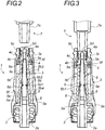
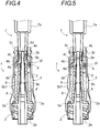
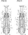
figures 2 à 10 sont des représentations schématiques en coupe longitudinale du connecteur selon l'invention selon un premier mode de réalisation. - les
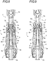
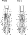
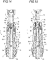
figures 11 à 15 sont des représentations schématiques en coupe longitudinale du connecteur selon l'invention selon un second mode de réalisation.
- the
figure 1 is a schematic perspective representation of a connector for medical use according to the invention. - the
figures 2 to 10 are schematic representations in longitudinal section of the connector according to the invention according to a first embodiment. - the
Figures 11 to 15 are schematic representations in longitudinal section of the connector according to the invention according to a second embodiment.
En référence notamment à la
Le compartiment distal (3c) de la chambre (3) présente une section apte à recevoir, par friction, un connecteur (7) de type luer mâle. Le compartiment proximal (3a) de la chambre (3) coopère avec le raccord (2), destiné à recevoir un cathéter reliant le patient et dans lequel circule un fluide.The distal compartment (3c) of the chamber (3) has a section capable of receiving, by friction, a connector (7) of the male luer type. The proximal compartment (3a) of the chamber (3) cooperates with the connector (2), intended to receive a catheter connecting the patient and in which a fluid circulates.
Comme le montrent les
L'aiguille (6) proprement dite est munie, à proximité de son extrémité libre, elle-même obturée, de deux orifices supérieurs latéraux (6a) par lesquels s'écoule le fluide lorsque sa partie distale est découverte, c'est-à-dire en position connectée. L'aiguille (6) est en effet gainée sur toute sa longueur dans l'empreinte d'un joint élastique (5) dont la partie terminale est cerclée par une bague (4). L'extrémité distale au moins de l'aiguille (6) présente une forme sensiblement conique de manière à favoriser son dégagement sous l'effet de la poussée exercée par le connecteur (7) type luer mâle sur l'ensemble bague (4)/joint élastique (5).The needle (6) proper is provided, near its free end, itself closed, with two lateral upper orifices (6a) through which the fluid flows when its distal part is uncovered, that is to say - say in the connected position. The needle (6) is in fact sheathed over its entire length in the imprint of an elastic seal (5) whose end part is encircled by a ring (4). The distal end at least of the needle (6) has a substantially conical shape so as to favor its release under the effect of the push exerted by the connector (7) male luer type on the ring assembly (4) / elastic seal (5).
L'aiguille (6) comprend selon l'invention, deux orifices supplémentaires inférieurs latéraux (6b), ménagés dans sa partie médiane. Ils sont diamétralement opposés l'un à l'autre.The needle (6) comprises according to the invention, two additional lateral lower orifices (6b), formed in its middle part. They are diametrically opposed to each other.
Dans le mode de réalisation objet des
Le joint élastique (5) est réalisé en silicone et se présente sous la forme d'un tube de section externe de forme générale conique, destiné à s'étendre dans la chambre (3) depuis le corps du raccord (2) jusqu'à l'extrémité libre du compartiment terminal (3c) de la chambre (3). Le joint (5) comprend une partie formant base (5a), une partie médiane (5b) et une partie terminale (5c).The elastic seal (5) is made of silicone and is in the form of a tube of external section of generally conical shape, intended to extend in the chamber (3) from the body of the fitting (2) to the free end of the terminal compartment (3c) of the chamber (3). The seal (5) comprises a base part (5a), a middle part (5b) and an end part (5c).
La partie formant base (5a) du joint élastique (5) est destinée à reposer sur le corps du raccord (2). En position non comprimée, c'est-à-dire en position relâchée, ni la partie formant base (5a) du joint élastique (5), ni la partie médiane (5b) ne sont en contact avec les parois de la chambre (3).The base part (5a) of the elastic seal (5) is intended to rest on the body of the fitting (2). In the uncompressed position, that is to say in the relaxed position, neither the base part (5a) of the elastic seal (5), nor the middle part (5b) are in contact with the walls of the chamber (3 ).
La paroi interne de la partie médiane (5b) du joint élastique (5) comprend un bourrelet périphérique (5b1) positionné de sorte à obturer les orifices latéraux inférieurs (6b) de l'aiguille en position relâchée du joint, c'est-à-dire hors connexion.The inner wall of the middle part (5b) of the elastic seal (5) comprises a peripheral bead (5b1) positioned so as to close the lower lateral orifices (6b) of the needle in the released position of the seal, i.e. - say offline.
Directement en aval de ce bourrelet, la paroi interne du joint présente une forme conique (5b2) complémentaire de celle de l'aiguille, en contact avec celle-ci. La face externe du joint à ce niveau est rectiligne et plus rigide que le reste du joint. Le caractère rigide peut être renforcé en ménageant des rainures longitudinales sur la portion de joint correspondante. En aval de cette zone rectiligne 5b2, la paroi du joint élastique 5b3 jusqu'à son extrémité distale est constituée d'une succession de bourrelets. De même, dans sa partie 5b4 située en amont du bourrelet périphérique (5b1), la paroi du joint est constituée d'une succession de bourrelets jusqu'à son extrémité amont.Directly downstream of this bead, the internal wall of the seal has a conical shape (5b2) complementary to that of the needle, in contact with the latter. The outer face of the joint at this level is straight and more rigid than the rest of the joint. The rigid nature can be reinforced by providing longitudinal grooves on the corresponding joint portion. Downstream of this rectilinear zone 5b2, the wall of the elastic seal 5b3 up to its distal end consists of a succession of beads. Similarly, in its part 5b4 located upstream of the peripheral bead (5b1), the wall of the seal consists of a succession of beads up to its upstream end.
La cinématique du joint élastique au moment de la connexion et de la déconnexion est la suivante.The kinematics of the elastic joint at the time of connection and disconnection is as follows.
Comme le montrent les
Lorsque le joint élastique (5) retourne dans une position relâchée, le bourrelet inférieur (5b1) remonte progressivement et pousse le liquide présent dans le volume mort étanche (9) à l'intérieur de l'aiguille (6) par les orifices latéraux inférieurs (6b). La cinématique du joint élastique (
Dans une seconde forme de réalisation de l'invention, représentée aux
Dans ce mode de réalisation, le joint élastique présente encore sur sa paroi interne, un bourrelet périphérique (5b1) désigné dans ce cas «premier bourrelet » apte à obturer les deux orifices supplémentaires (6b).In this embodiment, the elastic seal also has on its internal wall, a peripheral bead (5b1) designated in this case "first bead" capable of closing the two additional orifices (6b).
Immédiatement en aval du premier bourrelet périphérique (5b1), la paroi interne du joint présente un tronçon de forme tubulaire (10) délimité en aval par un second bourrelet périphérique (5b2) maintenu en contact serré avec l'aiguille. L'ensemble forme ainsi une cavité (11) dont la paroi (10) est plus rigide que celle du reste du joint.Immediately downstream of the first peripheral bead (5b1), the internal wall of the joint has a tubular section (10) delimited downstream by a second peripheral bead (5b2) maintained in close contact with the needle. The assembly thus forms a cavity (11) whose wall (10) is more rigid than that of the rest of the joint.
Toujours dans ce second mode de réalisation, l'aiguille présente directement en aval de l'orifice supplémentaire, un rebord périphérique (6c) d'appui et de fin de course du second bourrelet périphérique (5b2) en position comprimée du joint élastique. Ce bourrelet (6c) permet de conférer au volume mort (9) une étanchéité optimale en position connectée. Il fait également office de butée pour le bourrelet inférieur (5b1) en position relâchée du joint élastique (5). De la sorte, le liquide ne peut circuler en aval du rebord périphérique (6c) en direction aval, entre la paroi élastique et le fut de l'aiguille.Still in this second embodiment, the needle has, directly downstream of the additional orifice, a peripheral rim (6c) for supporting and end of travel of the second peripheral bead (5b2) in the compressed position of the elastic seal. This bead (6c) makes it possible to give the dead volume (9) an optimal seal in the connected position. It also acts as a stop for the lower bead (5b1) in the relaxed position of the elastic seal (5). In this way, the liquid cannot circulate downstream of the peripheral rim (6c) in the downstream direction, between the elastic wall and the barrel of the needle.
De même que précédemment, le volume de la cavité, les caractéristiques élastiques des parties du joint en amont et en aval de la cavité de même que la taille de l'orifice supplémentaire sont calculés pour que la partie du joint en aval de la cavité remonte plus vite que la partie en amont de la cavité.As previously, the volume of the cavity, the elastic characteristics of the parts of the seal upstream and downstream of the cavity as well as the size of the additional orifice are calculated so that the part of the seal downstream of the cavity rises faster than the upstream part of the cavity.
En pratique, lors de la compression du joint élastique (5), c'est-à-dire au moment de la connexion avec un connecteur (7) type luer mâle, la cavité (11) subit un mouvement de translation en direction amont du connecteur. Le bourrelet inférieur (5b1) découvre ainsi les orifices (6c), de sorte que la cavité se remplit progressivement du fluide circulant dans le fut de l'aiguille. La cavité termine sa course lorsque le second bourrelet périphérique (5b2) vient en appui sur le rebord périphérique de l'aiguille (6c).In practice, during compression of the elastic seal (5), that is to say at the time of connection with a connector (7) of the male luer type, the cavity (11) undergoes a translational movement in the upstream direction of the connector. The lower bead (5b1) thus uncovers the orifices (6c), so that the cavity gradually fills with the fluid circulating in the barrel of the needle. The cavity ends its stroke when the second peripheral bead (5b2) comes to bear on the peripheral rim of the needle (6c).
Lorsque le joint élastique (5) retourne dans une position initiale par effet ressort, le bourrelet inférieur (5b1) remonte et pousse le liquide, par un phénomène de raclage, à l'intérieur de l'aiguille (6) via les orifices latéraux inférieurs (6b), et ce, jusqu'à que ledit bourrelet inférieur (5b1) retourne dans sa position d'origine d'obturation des orifices latéraux inférieurs (6b) de l'aiguille (6). Avant que les orifices latéraux inférieurs ne soit obturés, la partie du joint en aval de la cavité a déjà obturé les orifices débouchant de l'aiguille. Comme déjà mentionné, le volume de liquide est confiné dans la partie de la cavité située en amont de l'orifice supplémentaire et ne peut circuler au-delà du rebord périphérique (6b) que ce soit lors de la connexion ou de la deconnexion.When the elastic seal (5) returns to an initial position by spring effect, the lower bead (5b1) rises and pushes the liquid, by a scraping phenomenon, inside the needle (6) via the lower lateral orifices (6b), and this, until said lower bead (5b1) returns to its original position for closing the lower lateral orifices (6b) of the needle (6). Before the lower lateral openings are closed, the part of the seal downstream of the cavity has already closed the openings opening out from the needle. As already mentioned, the volume of liquid is confined in the part of the cavity located upstream of the additional orifice and cannot circulate beyond the peripheral rim (6b) either during connection or disconnection.
Le volume de fluide ainsi réintroduit dans le fut de l'aiguille crée une pression permettant de compenser la dépression engendrée par la déconnexion au niveau de la partie terminale de l'aiguille (6) et ainsi éviter tout risque de remontée indésirable de fluide.The volume of fluid thus reintroduced into the barrel of the needle creates a pressure making it possible to compensate for the depression generated by the disconnection at the level of the terminal part of the needle (6) and thus avoid any risk of undesirable rise of fluid.
Dans le connecteur (1) selon l'invention, quel que soit le mode de réalisation, la partie terminale (5c) du joint élastique (5) est en outre munie d'une fente (5d), permettant le passage de l'aiguille (6), lorsque le joint élastique (5) se trouve dans une position dite « comprimée ». La partie terminale (5c) du joint élastique (5) comprend en outre un évidement (5e) en amont de l'extrémité de l'aiguille (6) en position non comprimée du joint élastique (5). La partie terminale (5c) présente également une collerette (5f), qui permet le guidage et le centrage de ladite partie terminale (5c) du joint élastique (5) dans le compartiment central (3b) de la chambre (3). Pour tenir compte de la forme et des dimensions du compartiment central (3b) de la chambre (3), cette collerette (5f) est également cerclée par la bague (4).In the connector (1) according to the invention, whatever the embodiment, the end part (5c) of the elastic seal (5) is further provided with a slot (5d), allowing the passage of the needle (6), when the elastic seal (5) is in a position called "compressed". The end portion (5c) of the elastic seal (5) further comprises a recess (5e) upstream of the end of the needle (6) in the uncompressed position of the elastic seal (5). The end part (5c) also has a flange (5f), which allows the guiding and centering of said end part (5c) of the elastic seal (5) in the central compartment (3b) of the chamber (3). To take account of the shape and dimensions of the central compartment (3b) of the chamber (3), this flange (5f) is also surrounded by the ring (4).
La bague (4) est positionnée à l'extrémité du joint élastique (5) et présente deux tronçons de sections différentes, respectivement un premier tronçon cylindrique (4a) cerclant la partie terminale (5c) du joint élastique (5) sur une longueur correspondant à la longueur du compartiment terminal (3c) et de section sensiblement égale à la section dudit compartiment terminal (3c) et un second tronçon cylindrique (4b), de section supérieure sensiblement égale à la section correspondante du compartiment central (3b) et recouvrant la collerette (5f) du joint élastique (5). La bague (4) est réalisée en un matériau rigide ou semi-rigide, éventuellement en bi-matière avec le joint élastique (5), ou séparément, bague (4) et joint (5) étant rendus solidaires l'un de l'autre notamment par collage ou simple apposition. La section externe du joint (5) est sensiblement égale à la section interne de la bague (4) sur leur zone de recouvrement.The ring (4) is positioned at the end of the elastic seal (5) and has two sections of different sections, respectively a first cylindrical section (4a) encircling the end part (5c) of the elastic seal (5) over a corresponding length the length of the terminal compartment (3c) and of section substantially equal to the section of said terminal compartment (3c) and a second cylindrical section (4b), of upper section substantially equal to the corresponding section of the central compartment (3b) and covering the flange (5f) of the elastic seal (5). The ring (4) is made of a rigid or semi-rigid material, possibly made of two materials with the elastic seal (5), or separately, ring (4) and seal (5) being made integral with one of the other in particular by gluing or simple affixing. The external section of the seal (5) is substantially equal to the internal section of the ring (4) on their overlap zone.
Telle que représenté aux
Le compartiment central (3b) et le compartiment terminal (3c) sont reliés par un épaulement servant de butée à la bague (4) cerclant l'extrémité terminale (5c) du joint élastique (5) en position de repos, c'est-à-dire en position de relâchement du joint.
La position connectée est plus précisément représentée aux
The connected position is more precisely represented in
En position connectée, l'extrémité distale de l'aiguille (6) est donc dans sa totalité, contenue dans le canal intérieur du cône (7a), permettant ainsi la transmission du fluide de connecteur (1) à connecteur (7). Le mouvement de la bague (4) pendant cette opération, est un mouvement axial homogène et uniforme de par le contact permanent des parois de la section de la bague (4) avec le compartiment central (3b) de la chambre (3) tout au long du mouvement, moyennant un minimum de friction.In the connected position, the distal end of the needle (6) is therefore in its entirety, contained in the inner channel of the cone (7a), thus allowing the transmission of the fluid from connector (1) to connector (7). The movement of the ring (4) during this operation is a homogeneous and uniform axial movement due to the permanent contact of the walls of the section of the ring (4) with the central compartment (3b) of the chamber (3) at the along the movement, with minimal friction.
Comme il ressort de ce qui précède, l'invention fournit un connecteur (1) à usage médical donnant entière satisfaction d'utilisation. On note en particulier la compensation de la remontée indésirable de fluide liée à la déconnexion du connecteur (1).As appears from the above, the invention provides a connector (1) for medical use giving complete satisfaction of use. We note in particular the compensation for the undesirable rise of fluid linked to the disconnection of the connector (1).
Claims (12)
- Medical connector (1) comprising a joint (2) fixed to a chamber (3), the joint (2) being provided at its centre with a needle (6) extending into said chamber (3) and opening into its terminal end, which has a section suitable for receiving, by friction, a male luer connector (7) for the circulation of a fluid; the needle (6) has a distal portion with at least one lateral hole (6a) opening into and contained in a cavity (5g) of a resilient seal (5) having, in the thickness of its free end, a slit (5d) or a similar opening, the resilient seal being compressed when connected to uncover the distal portion of the needle and ensure the transfer of fluid, and released when disconnected, the needle having, apart from its distal portion, at least one additional hole (6b), the resilient seal and the needle (6) being shaped so that:- when the connector is not connected, at least one additional hole (6b) is closed by the resilient seal (5), and- when the connector is connected, at least one additional hole (6b) is not closed by the resilient seal (5);characterised in that the resilient seal and the needle (6) are also shaped so that:- when the connector (1) is connected, the resilient seal (5) in the compressed state forms with the needle (6), immediately upstream of the upper level of the additional hole (6b) and only on the portion of the distance separating the said hole of the upstream end from the seal, a sealed cavity (9) for receiving by way of passage in the additional hole (6b) a part of the fluid contained in the needle (6), and- when the resilient seal (5) goes from the compressed state to the released state:• the cavity (9) still contains fluid when the at least one lateral hole (6b) opening into the needle (6) is sealed by the resilient seal (5),• the portions of the resilient seal (5), downstream and upstream of the cavity (9) respectively, as well as the additional hole (6b) are shaped so that the downstream portion of the resilient seal (5) closes at least one lateral hole (6a) while the same cavity (9) continues to discharge the fluid contained therein into the needle (6).
- Connector according to claim 1, characterised in that the additional hole (6b) is formed in the middle portion of the needle (6).
- Connector according to one of claims 1 or 2, characterised in that:- the resilient seal (5) has on its inner wall a peripheral pad (5b 1) adapted to close at least one additional hole (6b),- immediately downstream of the hole (6b), on at least part of the distance separating said hole from the distal end of the needle (6), the needle (6) and the inner wall of the seal (5) are of complementary shape,- immediately upstream of the additional hole, the needle (6) and the inner wall of the seal (5) do not have a complementary shape.
- Connector according to claim 3, characterised in that the needle (6) and the inner wall of the seal (5) are of complementary shape on only part of the distance separating said hole from the distal end of the needle.
- Connector according to one of claims 3 or 4, characterised in that the wall of the part of the seal whose shape complements that of the needle (6) is stiffer than that of the rest of the seal.
- Connector according to one of claims 3 to 5, characterised in that:- the inner wall of the resilient seal (5) has a generally conical shape over its entire length,- immediately upstream of the additional hole (6b), the needle (6) has a cylindrical outer section.
- Connector according to claim 6, characterized in that immediately upstream of the additional hole (6b), the needle (6) has a first part with a cylindrical outer section (6d) and a second conical part with an outer section (6e) that increases towards the base of the needle.
- Connector according to one of claims 1 or 2, characterised in that:- the resilient seal (5) has on its inner wall a first peripheral pad (5b 1) adapted to close at least one additional hole (6b),- immediately downstream of the additional hole (6b), on at least part of the distance separating said hole from the distal end of the needle (6), the needle and the inner wall of the seal (5) are of non-complementary shape and demarcate a rigid, sealed cavity (9),- immediately downstream of the additional orifice, the needle has a peripheral edge with a section substantially identical or almost identical to that of the cavity.
- Connector according to claim 8, characterised in that immediately downstream of the first peripheral pad (5b 1), the inner wall of the seal (5) has a tubular portion demarcated downstream by a second peripheral bead (5b) held in tight contact with the needle (6).
- Connector according to one of claims 8 or 9, characterised in that the wall of the tubular portion is more rigid than the rest of the seal.
- Connector according to one of the preceding claims, characterised in that the wall of the seal upstream and downstream of the cavity is in the form of a succession of pads giving the parts of the seal identical rigidity downstream and upstream of the cavity.
- Connector according to one of the preceding claims, characterised in that there are two additional holes which are positioned opposite one another.
Priority Applications (1)
| Application Number | Priority Date | Filing Date | Title |
|---|---|---|---|
| PL14704617T PL2950876T3 (en) | 2013-01-31 | 2014-01-28 | Improved medical connector |
Applications Claiming Priority (2)
| Application Number | Priority Date | Filing Date | Title |
|---|---|---|---|
| FR1350836A FR3001393B1 (en) | 2013-01-31 | 2013-01-31 | IMPROVED MEDICAL CONNECTOR |
| PCT/FR2014/050153 WO2014118462A1 (en) | 2013-01-31 | 2014-01-28 | Improved medical connector |
Publications (2)
| Publication Number | Publication Date |
|---|---|
| EP2950876A1 EP2950876A1 (en) | 2015-12-09 |
| EP2950876B1 true EP2950876B1 (en) | 2020-04-15 |
Family
ID=48083367
Family Applications (1)
| Application Number | Title | Priority Date | Filing Date |
|---|---|---|---|
| EP14704617.1A Active EP2950876B1 (en) | 2013-01-31 | 2014-01-28 | Improved medical connector |
Country Status (6)
| Country | Link |
|---|---|
| US (1) | US9931497B2 (en) |
| EP (1) | EP2950876B1 (en) |
| ES (1) | ES2785318T3 (en) |
| FR (1) | FR3001393B1 (en) |
| PL (1) | PL2950876T3 (en) |
| WO (1) | WO2014118462A1 (en) |
Families Citing this family (10)
| Publication number | Priority date | Publication date | Assignee | Title |
|---|---|---|---|---|
| US8323249B2 (en) | 2009-08-14 | 2012-12-04 | The Regents Of The University Of Michigan | Integrated vascular delivery system |
| WO2011146769A2 (en) | 2010-05-19 | 2011-11-24 | Tangent Medical Technologies Llc | Integrated vascular delivery system |
| US8814833B2 (en) | 2010-05-19 | 2014-08-26 | Tangent Medical Technologies Llc | Safety needle system operable with a medical device |
| CN105163796B (en) | 2013-03-15 | 2018-06-01 | Icu医学有限公司 | Medical connector |
| AU2014364218B2 (en) | 2013-12-11 | 2019-06-06 | Icu Medical, Inc. | Check valve |
| EP3102258A4 (en) | 2014-02-04 | 2017-12-27 | ICU Medical, Inc. | Self-priming systems and methods |
| USD786427S1 (en) | 2014-12-03 | 2017-05-09 | Icu Medical, Inc. | Fluid manifold |
| USD793551S1 (en) | 2014-12-03 | 2017-08-01 | Icu Medical, Inc. | Fluid manifold |
| ITUB20152902A1 (en) * | 2015-08-05 | 2017-02-05 | Borla Ind | VALVE VALVE FOR MEDICAL LINES |
| GB2589134A (en) * | 2019-11-22 | 2021-05-26 | Overx Medical Ltd | A connector |
Family Cites Families (4)
| Publication number | Priority date | Publication date | Assignee | Title |
|---|---|---|---|---|
| US5776113A (en) * | 1996-03-29 | 1998-07-07 | Becton Dickinson And Company | Valved PRN adapter for medical access devices |
| ITTO20040524A1 (en) * | 2004-07-27 | 2004-10-27 | Borla Ind | VALVE CONNECTOR FOR MEDICAL INFUSION LINES |
| FR2894150B1 (en) | 2005-12-05 | 2008-01-04 | Ace Dev Solution Soc A Respons | CONNECTOR FOR MEDICAL USE |
| DE602007014252D1 (en) * | 2006-10-25 | 2011-06-09 | Icu Medical Inc | MEDICAL CONNECTOR |
-
2013
- 2013-01-31 FR FR1350836A patent/FR3001393B1/en active Active
-
2014
- 2014-01-28 EP EP14704617.1A patent/EP2950876B1/en active Active
- 2014-01-28 WO PCT/FR2014/050153 patent/WO2014118462A1/en active Application Filing
- 2014-01-28 PL PL14704617T patent/PL2950876T3/en unknown
- 2014-01-28 ES ES14704617T patent/ES2785318T3/en active Active
- 2014-01-28 US US14/652,612 patent/US9931497B2/en active Active
Non-Patent Citations (1)
| Title |
|---|
| None * |
Also Published As
| Publication number | Publication date |
|---|---|
| ES2785318T3 (en) | 2020-10-06 |
| EP2950876A1 (en) | 2015-12-09 |
| FR3001393B1 (en) | 2015-01-23 |
| US9931497B2 (en) | 2018-04-03 |
| WO2014118462A1 (en) | 2014-08-07 |
| US20160001057A1 (en) | 2016-01-07 |
| PL2950876T3 (en) | 2020-09-21 |
| FR3001393A1 (en) | 2014-08-01 |
Similar Documents
| Publication | Publication Date | Title |
|---|---|---|
| EP2950876B1 (en) | Improved medical connector | |
| EP1890760B1 (en) | Connector for medical use | |
| CA2843149C (en) | Non-drip, direct-flow connectors with secure locking | |
| EP2170448B1 (en) | Device for introducing a catheter guide wire into a vessel | |
| CA2790033C (en) | Set of easily cleanable connectors for a liquid circuit | |
| CA2083670C (en) | Composite coupling unit for liquid circuit especially for medical use | |
| EP2882487B1 (en) | Connector for medical use | |
| EP2296733B1 (en) | Device for injecting fluid for medical use | |
| FR2988006A1 (en) | SECURE LIQUID TRANSFER ASSEMBLY FOR MEDICAL USE | |
| FR2931681A1 (en) | SYRINGE WITH UNIVERSAL TIP | |
| CA2982611A1 (en) | Medical valve, kit comprising such a valve, and method for preparing a mixture or an emulsion | |
| EP3164223A1 (en) | Device for dispensing a fluid product | |
| CA2793097A1 (en) | Secure transfer process for a medical use liquid | |
| FR2475903A1 (en) | Safety coupling for cannulae or catheters - comprises cone penetrating elastomeric disc with slit, which closes passage if coupling breaks | |
| EP3319667B1 (en) | Syringe and method for assembling it | |
| EP2341975B1 (en) | Multipurpose male fluidic coupling for a coupling device and device such as this incorporating it | |
| FR2923393A1 (en) | DEVICE FOR ADMINISTERING MULTIPLE MEDICAL TREATMENT LIQUIDS TO A PATIENT | |
| FR2644349A1 (en) | SINGLE USE SYRINGE | |
| FR2952813A1 (en) | Device for connecting containers for transforming e.g. liquid during medical intervention, has obturation unit movably mounted between rest position and active position in which obturation unit brings valve in opened position | |
| FR2929123A1 (en) | CONNECTOR FOR IMPROVED MEDICAL USE | |
| FR2794651A1 (en) | SAFETY SINGLE USE SYRINGE |
Legal Events
| Date | Code | Title | Description |
|---|---|---|---|
| PUAI | Public reference made under article 153(3) epc to a published international application that has entered the european phase |
Free format text: ORIGINAL CODE: 0009012 |
|
| 17P | Request for examination filed |
Effective date: 20150623 |
|
| AK | Designated contracting states |
Kind code of ref document: A1 Designated state(s): AL AT BE BG CH CY CZ DE DK EE ES FI FR GB GR HR HU IE IS IT LI LT LU LV MC MK MT NL NO PL PT RO RS SE SI SK SM TR |
|
| AX | Request for extension of the european patent |
Extension state: BA ME |
|
| DAX | Request for extension of the european patent (deleted) | ||
| STAA | Information on the status of an ep patent application or granted ep patent |
Free format text: STATUS: EXAMINATION IS IN PROGRESS |
|
| 17Q | First examination report despatched |
Effective date: 20180612 |
|
| GRAP | Despatch of communication of intention to grant a patent |
Free format text: ORIGINAL CODE: EPIDOSNIGR1 |
|
| STAA | Information on the status of an ep patent application or granted ep patent |
Free format text: STATUS: GRANT OF PATENT IS INTENDED |
|
| INTG | Intention to grant announced |
Effective date: 20191106 |
|
| RIN1 | Information on inventor provided before grant (corrected) |
Inventor name: LOPEZ, GEORGES ANTOINE Inventor name: DELORME, PATRICK |
|
| GRAS | Grant fee paid |
Free format text: ORIGINAL CODE: EPIDOSNIGR3 |
|
| GRAA | (expected) grant |
Free format text: ORIGINAL CODE: 0009210 |
|
| STAA | Information on the status of an ep patent application or granted ep patent |
Free format text: STATUS: THE PATENT HAS BEEN GRANTED |
|
| AK | Designated contracting states |
Kind code of ref document: B1 Designated state(s): AL AT BE BG CH CY CZ DE DK EE ES FI FR GB GR HR HU IE IS IT LI LT LU LV MC MK MT NL NO PL PT RO RS SE SI SK SM TR |
|
| REG | Reference to a national code |
Ref country code: CH Ref legal event code: EP |
|
| REG | Reference to a national code |
Ref country code: NL Ref legal event code: FP |
|
| REG | Reference to a national code |
Ref country code: DE Ref legal event code: R096 Ref document number: 602014063747 Country of ref document: DE |
|
| REG | Reference to a national code |
Ref country code: IE Ref legal event code: FG4D Free format text: LANGUAGE OF EP DOCUMENT: FRENCH |
|
| REG | Reference to a national code |
Ref country code: AT Ref legal event code: REF Ref document number: 1256535 Country of ref document: AT Kind code of ref document: T Effective date: 20200515 |
|
| REG | Reference to a national code |
Ref country code: LT Ref legal event code: MG4D |
|
| REG | Reference to a national code |
Ref country code: ES Ref legal event code: FG2A Ref document number: 2785318 Country of ref document: ES Kind code of ref document: T3 Effective date: 20201006 |
|
| PG25 | Lapsed in a contracting state [announced via postgrant information from national office to epo] |
Ref country code: LT Free format text: LAPSE BECAUSE OF FAILURE TO SUBMIT A TRANSLATION OF THE DESCRIPTION OR TO PAY THE FEE WITHIN THE PRESCRIBED TIME-LIMIT Effective date: 20200415 Ref country code: FI Free format text: LAPSE BECAUSE OF FAILURE TO SUBMIT A TRANSLATION OF THE DESCRIPTION OR TO PAY THE FEE WITHIN THE PRESCRIBED TIME-LIMIT Effective date: 20200415 Ref country code: IS Free format text: LAPSE BECAUSE OF FAILURE TO SUBMIT A TRANSLATION OF THE DESCRIPTION OR TO PAY THE FEE WITHIN THE PRESCRIBED TIME-LIMIT Effective date: 20200815 Ref country code: SE Free format text: LAPSE BECAUSE OF FAILURE TO SUBMIT A TRANSLATION OF THE DESCRIPTION OR TO PAY THE FEE WITHIN THE PRESCRIBED TIME-LIMIT Effective date: 20200415 Ref country code: GR Free format text: LAPSE BECAUSE OF FAILURE TO SUBMIT A TRANSLATION OF THE DESCRIPTION OR TO PAY THE FEE WITHIN THE PRESCRIBED TIME-LIMIT Effective date: 20200716 Ref country code: PT Free format text: LAPSE BECAUSE OF FAILURE TO SUBMIT A TRANSLATION OF THE DESCRIPTION OR TO PAY THE FEE WITHIN THE PRESCRIBED TIME-LIMIT Effective date: 20200817 Ref country code: NO Free format text: LAPSE BECAUSE OF FAILURE TO SUBMIT A TRANSLATION OF THE DESCRIPTION OR TO PAY THE FEE WITHIN THE PRESCRIBED TIME-LIMIT Effective date: 20200715 |
|
| REG | Reference to a national code |
Ref country code: AT Ref legal event code: MK05 Ref document number: 1256535 Country of ref document: AT Kind code of ref document: T Effective date: 20200415 |
|
| PG25 | Lapsed in a contracting state [announced via postgrant information from national office to epo] |
Ref country code: RS Free format text: LAPSE BECAUSE OF FAILURE TO SUBMIT A TRANSLATION OF THE DESCRIPTION OR TO PAY THE FEE WITHIN THE PRESCRIBED TIME-LIMIT Effective date: 20200415 Ref country code: BG Free format text: LAPSE BECAUSE OF FAILURE TO SUBMIT A TRANSLATION OF THE DESCRIPTION OR TO PAY THE FEE WITHIN THE PRESCRIBED TIME-LIMIT Effective date: 20200715 Ref country code: LV Free format text: LAPSE BECAUSE OF FAILURE TO SUBMIT A TRANSLATION OF THE DESCRIPTION OR TO PAY THE FEE WITHIN THE PRESCRIBED TIME-LIMIT Effective date: 20200415 Ref country code: HR Free format text: LAPSE BECAUSE OF FAILURE TO SUBMIT A TRANSLATION OF THE DESCRIPTION OR TO PAY THE FEE WITHIN THE PRESCRIBED TIME-LIMIT Effective date: 20200415 |
|
| PG25 | Lapsed in a contracting state [announced via postgrant information from national office to epo] |
Ref country code: AL Free format text: LAPSE BECAUSE OF FAILURE TO SUBMIT A TRANSLATION OF THE DESCRIPTION OR TO PAY THE FEE WITHIN THE PRESCRIBED TIME-LIMIT Effective date: 20200415 |
|
| REG | Reference to a national code |
Ref country code: DE Ref legal event code: R097 Ref document number: 602014063747 Country of ref document: DE |
|
| PG25 | Lapsed in a contracting state [announced via postgrant information from national office to epo] |
Ref country code: CZ Free format text: LAPSE BECAUSE OF FAILURE TO SUBMIT A TRANSLATION OF THE DESCRIPTION OR TO PAY THE FEE WITHIN THE PRESCRIBED TIME-LIMIT Effective date: 20200415 Ref country code: RO Free format text: LAPSE BECAUSE OF FAILURE TO SUBMIT A TRANSLATION OF THE DESCRIPTION OR TO PAY THE FEE WITHIN THE PRESCRIBED TIME-LIMIT Effective date: 20200415 Ref country code: EE Free format text: LAPSE BECAUSE OF FAILURE TO SUBMIT A TRANSLATION OF THE DESCRIPTION OR TO PAY THE FEE WITHIN THE PRESCRIBED TIME-LIMIT Effective date: 20200415 Ref country code: SM Free format text: LAPSE BECAUSE OF FAILURE TO SUBMIT A TRANSLATION OF THE DESCRIPTION OR TO PAY THE FEE WITHIN THE PRESCRIBED TIME-LIMIT Effective date: 20200415 Ref country code: AT Free format text: LAPSE BECAUSE OF FAILURE TO SUBMIT A TRANSLATION OF THE DESCRIPTION OR TO PAY THE FEE WITHIN THE PRESCRIBED TIME-LIMIT Effective date: 20200415 Ref country code: DK Free format text: LAPSE BECAUSE OF FAILURE TO SUBMIT A TRANSLATION OF THE DESCRIPTION OR TO PAY THE FEE WITHIN THE PRESCRIBED TIME-LIMIT Effective date: 20200415 |
|
| PLBE | No opposition filed within time limit |
Free format text: ORIGINAL CODE: 0009261 |
|
| STAA | Information on the status of an ep patent application or granted ep patent |
Free format text: STATUS: NO OPPOSITION FILED WITHIN TIME LIMIT |
|
| PG25 | Lapsed in a contracting state [announced via postgrant information from national office to epo] |
Ref country code: SK Free format text: LAPSE BECAUSE OF FAILURE TO SUBMIT A TRANSLATION OF THE DESCRIPTION OR TO PAY THE FEE WITHIN THE PRESCRIBED TIME-LIMIT Effective date: 20200415 |
|
| 26N | No opposition filed |
Effective date: 20210118 |
|
| PG25 | Lapsed in a contracting state [announced via postgrant information from national office to epo] |
Ref country code: SI Free format text: LAPSE BECAUSE OF FAILURE TO SUBMIT A TRANSLATION OF THE DESCRIPTION OR TO PAY THE FEE WITHIN THE PRESCRIBED TIME-LIMIT Effective date: 20200415 |
|
| PG25 | Lapsed in a contracting state [announced via postgrant information from national office to epo] |
Ref country code: MC Free format text: LAPSE BECAUSE OF FAILURE TO SUBMIT A TRANSLATION OF THE DESCRIPTION OR TO PAY THE FEE WITHIN THE PRESCRIBED TIME-LIMIT Effective date: 20200415 |
|
| PG25 | Lapsed in a contracting state [announced via postgrant information from national office to epo] |
Ref country code: LU Free format text: LAPSE BECAUSE OF NON-PAYMENT OF DUE FEES Effective date: 20210128 |
|
| PG25 | Lapsed in a contracting state [announced via postgrant information from national office to epo] |
Ref country code: IE Free format text: LAPSE BECAUSE OF NON-PAYMENT OF DUE FEES Effective date: 20210128 |
|
| PGFP | Annual fee paid to national office [announced via postgrant information from national office to epo] |
Ref country code: PL Payment date: 20221220 Year of fee payment: 10 |
|
| PGFP | Annual fee paid to national office [announced via postgrant information from national office to epo] |
Ref country code: FR Payment date: 20230127 Year of fee payment: 10 Ref country code: ES Payment date: 20230206 Year of fee payment: 10 Ref country code: CH Payment date: 20230130 Year of fee payment: 10 |
|
| PG25 | Lapsed in a contracting state [announced via postgrant information from national office to epo] |
Ref country code: HU Free format text: LAPSE BECAUSE OF FAILURE TO SUBMIT A TRANSLATION OF THE DESCRIPTION OR TO PAY THE FEE WITHIN THE PRESCRIBED TIME-LIMIT; INVALID AB INITIO Effective date: 20140128 |
|
| PGFP | Annual fee paid to national office [announced via postgrant information from national office to epo] |
Ref country code: TR Payment date: 20230123 Year of fee payment: 10 Ref country code: IT Payment date: 20230111 Year of fee payment: 10 Ref country code: GB Payment date: 20230123 Year of fee payment: 10 Ref country code: DE Payment date: 20230112 Year of fee payment: 10 Ref country code: BE Payment date: 20230117 Year of fee payment: 10 |
|
| PG25 | Lapsed in a contracting state [announced via postgrant information from national office to epo] |
Ref country code: CY Free format text: LAPSE BECAUSE OF FAILURE TO SUBMIT A TRANSLATION OF THE DESCRIPTION OR TO PAY THE FEE WITHIN THE PRESCRIBED TIME-LIMIT Effective date: 20200415 |
|
| PGFP | Annual fee paid to national office [announced via postgrant information from national office to epo] |
Ref country code: NL Payment date: 20231229 Year of fee payment: 11 |
|
| PGFP | Annual fee paid to national office [announced via postgrant information from national office to epo] |
Ref country code: PL Payment date: 20231219 Year of fee payment: 11 |
|
| PGFP | Annual fee paid to national office [announced via postgrant information from national office to epo] |
Ref country code: ES Payment date: 20240207 Year of fee payment: 11 |