EP2950088A1 - Electrochemical measurement device - Google Patents
Electrochemical measurement device Download PDFInfo
- Publication number
- EP2950088A1 EP2950088A1 EP14743319.7A EP14743319A EP2950088A1 EP 2950088 A1 EP2950088 A1 EP 2950088A1 EP 14743319 A EP14743319 A EP 14743319A EP 2950088 A1 EP2950088 A1 EP 2950088A1
- Authority
- EP
- European Patent Office
- Prior art keywords
- current value
- electrochemical measurement
- measurement
- unit
- flow cell
- Prior art date
- Legal status (The legal status is an assumption and is not a legal conclusion. Google has not performed a legal analysis and makes no representation as to the accuracy of the status listed.)
- Granted
Links
Images


Classifications
-
- G—PHYSICS
- G01—MEASURING; TESTING
- G01N—INVESTIGATING OR ANALYSING MATERIALS BY DETERMINING THEIR CHEMICAL OR PHYSICAL PROPERTIES
- G01N27/00—Investigating or analysing materials by the use of electric, electrochemical, or magnetic means
- G01N27/26—Investigating or analysing materials by the use of electric, electrochemical, or magnetic means by investigating electrochemical variables; by using electrolysis or electrophoresis
- G01N27/416—Systems
- G01N27/4163—Systems checking the operation of, or calibrating, the measuring apparatus
Definitions
- the present invention relates to an electrochemical measurement device that performs electrochemical measurement using a flow cell.
- Electrochemical measurement means a method of measuring properties of chemical substances electrically.
- an electrochemical measurement flow cell disclosed in PTL 1 is known.
- the electrochemical measurement flow cell has a structure in which a flow channel is provided in a body having chemical resistance such as PEEK and electrodes are arranged to contact the flow channel and is mainly used as a detector of liquid chromatography or flow injection analysis.
- the electrodes used for the electrochemical measurement generally include three kinds of electrodes to be a working electrode, a counter electrode, and a reference electrode.
- the working electrode and the counter electrode among these electrodes stable metals such as platinum are used to prevent the electrodes from affecting a reaction of the measurement target.
- the reference electrode is an electrode having a special function of maintaining a potential constantly and a silver/silver chloride electrode is used as the reference electrode.
- the electrochemical measurement flow cell is generally used for the repetitive measurement after the appropriate cleaning. Because the electrochemical measurement flow cell has a relatively complicated structure with the electrodes and the flow channel, it is not preferable to use the electrochemical measurement flow cell as a disposable product, from the viewpoint of a cost and maintenance. As the electrochemical measurement flow cell is repetitively used, a measurement value may be changed due to a change of an electrode property, a change of a flow channel structure, and contamination of an inner portion of the flow cell. In addition, the measurement value may not be correctly obtained due to unexpected events such as adhesion of a chemical substance to an electrode surface, mixture of air bubbles in the flow channel, and damages of the electrodes. As described above, in the abnormal case, it may be predicted that a current flowing between the electrodes changes as compared with the normal case, the abnormality may be detected by monitoring a current value, and the possibility of incorrect measurement may be communicated.
- a value of a current flowing between the electrodes at the time of applying a voltage in the electrochemical measurement flow cell may not be necessarily the same value by an individual difference of such as the electrochemical measurement flow cell, the measurement device, and the measurement target solution or a combination thereof. For this reason, it is difficult to determine a constant threshold value common to all flow cells and detect the possibility of measurement abnormality by a comparison with the threshold value.
- a main characteristic of the present invention is that an electrochemical measurement device performing measurement using a flow cell for electrochemical measurement which introduces a sample solution, applies a voltage between a working electrode and a counter electrode to analyze the sample solution electrochemically, discharges the sample solution, and performs the electrochemical measurement continuously
- the electrochemical measurement device includes: a control device including a current measurement unit which measures a value of a current flowing between electrodes at the time of applying a voltage, a storage unit which records the measured current value, a comparison unit which compares a current value measured at a cycle of a measurement target with a determination standard based on a current value obtained at a cycle before the cycle and stored in the storage unit, and a determination unit which determines whether the current value measured at the cycle of the measurement target is normal by the comparison unit; and a communication device which, when it is determined that the measured current value is not normal, communicates abnormality of the current value to an operator.
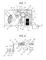
- FIG. 1 An electrochemical measurement flow cell and a measurement device to which the present invention is applied will be described using FIG. 1 .
- An automatic immunological analyzer includes a sample rack 100 to load a sample, a reagent disk 102 to store a reagent vessel 101, a sample dispensation mechanism 103 to fractionate/dispense the sample, a reagent dispensation mechanism 104 to fractionate/dispense reagents, a magnetic particle stirring mechanism 105 to stir a magnetic particle solution among the reagents, a reaction vessel 106 to put the fractionated sample and reagent and perform a reaction, a disposable dispensation chip 107 to be attached to a tip of the sample dispensation mechanism and to be used when the sample is fractionated/dispensed, a magazine 108 to store the reaction vessel and the dispensation chip, an incubator 109 to load the reagent and sample dispensed reaction vessel, maintain a temperature constantly, and perform the reaction, a conveyance mechanism 113 to convey the reaction vessel to the incubator and a reaction vessel disposing unit 110 and convey the dispensation chip to a dispensation chip mounting position 111 and a dispensation chip
- the electrochemical flow cell described in the present invention is mounted in a detector.
- Individual functions of controlling a voltage, measuring a current, recording a measured current, comparing a current value with a current value used as a determination standard, setting the current value used as the determination standard, and determining whether the current value is normal, which are described below, are realized by a microcomputer 121.
- the microcomputer 121 has functions of controlling an application voltage control unit, a current measurement unit, a current recording unit, a comparison unit with the determination standard, and a determination standard setting unit and determining whether the measured current value is normal.
- an electrochemical measurement flow cell 201 three kinds of electrodes including a working electrode 202, a counter electrode 203, and a reference electrode 204 are arranged to face a flow channel 205.
- a platinum electrode is used as the working electrode and the counter electrode and a silver/silver chloride electrode is used as the reference electrode.
- the electrochemical measurement flow cell and a nozzle 206 for solution suction are connected by an external flow channel 207 such as a tube.
- An external flow channel 208 is attached to the side of an outlet of the electrochemical measurement flow cell and a solution driving unit 209 such as a syringe pump is connected to a front portion thereof.
- a wiring line 210 is extracted from the three kinds of electrodes of the electrochemical measurement flow cell and the wiring line is connected to a voltage application/current measurement unit 211.
- the voltage application/current measurement unit is configured by a voltage control device such as a potentiostat and a power supply, for example.
- control of an application voltage and measurement of a current are performed by a control/operation/recording unit 212 realized by a computer and a computer program.
- current measurement values corresponding to a plurality of cycles needed in the present invention are recorded and operated by the control/operation/recording unit.
- the nozzle is driven in vertical and horizontal directions by a nozzle driving mechanism not illustrated in the drawings and can suck each of a solution 213 containing a measurement target substance, a cleaning liquid 214, and a buffering solution 215.
- the electrochemical measurement is repetitively performed including cleaning by the cleaning liquid while a plurality of measurement target substance solutions is measured.
- FIG. 3 a horizontal axis shows a time in a cycle and a vertical axis shows an application voltage of the working electrode for the reference electrode.
- a horizontal axis shows a time in a cycle
- a vertical axis shows an application voltage of the working electrode for the reference electrode.
- a buffering liquid is filled between the electrodes, a negative voltage is applied for 0.3 seconds, and an oxide film generated on a surface of the platinum electrode of the working electrode is removed. This process is called conditioning.
- a solution containing the measurement target substance is introduced between the electrodes, a positive voltage is applied to the working electrode for 1.4 seconds, and a current flowing at that time is measured. Because the flown current is proportional to an amount of the measurement target substance, the amount of the measurement target substance can be determined by measuring the current. This process is called the electrochemical measurement.
- a voltage higher than the voltage at the time of the electrochemical measurement is applied for 3.0 seconds in a state in which the cleaning liquid is filled between the electrodes and the measurement target substances remaining on the surfaces of the electrodes are removed. This process is called cleaning.
- a series of measurement manipulations described above is called a cycle.
- the oxide film is removed as a voltage application time passes and a current flowing between the electrodes increases. Voltages after 0.1, 0.2 and 0.3 seconds pass from application of a conditioning voltage are measured and recorded. At the time of the conditioning, if there is no large change in an electrode state, the current does not generally change greatly during several cycles. Therefore, it is determined that, when a current at a determination target cycle is compared with an average of currents at one cycle to three cycles before the determination target cycle and a difference of a predetermined threshold value, here, ⁇ 0.5 mA or more exists, the electrode state is abnormal.
- an amount determination result is not obtained normally and an erroneous result may be communicated.
- an alarm showing "abnormality of a current value is detected and measurement may not be correctly performed" is added to the result to urge a user to examine the measurement result carefully.
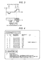
- FIG. 4 illustrates an example of a communication method for the user.
- current abnormality is detected by a method described in the present patent in fifth measurement, using the case in which a series of measurement results is displayed in a form of a list as an example.
- a field of a note of a measurement result display portion of No. 5 in a measurement value list "* current abnormality" is displayed.
- occurrence of "current abnormality” in the measurement of No. 5 and details of the abnormality and calling attention for the measurement result are displayed in a different field of alarm information.
- the user can know that the result may include a measurement error and can take a necessary countermeasure such as remeasurement and comparison with other measurement value.
- FIG. 5 illustrates currents after 0.1 seconds, 0.2 seconds, and 0.3 seconds pass from a voltage application start at a determination target cycle, one cycle before the determination target cycle, two cycles before the determination target cycle, and three cycles before the determination target cycle.
- an average value of the currents corresponding to the three cycles at each timing is illustrated.
- a difference of the current value of the determination target cycle and the average value is computed, the difference is compared with the predetermined threshold value, and propriety of the determination target cycle is determined.
- the current value at the determination target cycle decreases as compared with the current values at the cycles before the determination target cycle. For example, after 0.1 seconds, a difference with the average is 0.7 mA and is more than 0.5 mA to be the threshold value and thus, it is determined that there is the current abnormality at the determination target cycle.
- the electrode state it is necessary to use at least one point during application of a voltage when the electrode state is determined.
- three points (after 0.1 seconds, after 0.2 seconds, and after 0.3 seconds) are used.
- more points can be used. More points are used, so that the possibility of erroneously determining abnormality of a current value not including measurement abnormality occurred accidentally by electrical noise can be decreased.
- the current value becomes abnormal due to the abnormality of the measurement, it is predicted that values different from values in a normal state are obtained at all of a plurality of measurement points.
- the measurement may be determined as the abnormality.
- the normality or the abnormality of the measurement can be determined by recognizing patterns of waveforms using all of the points at which the current has been measured.
- the three cycles before the determination target cycle are used as the cycles to calculate the reference value to determine the propriety of the electrode state at the determination target cycle.
- the cycle immediately before the determination target cycle can be used or more cycles can be used. Even in any case, a determination method is the same as the method described herein.
- the threshold value used for the determination can be calculated from the value measured immediately after the electrochemical measurement flow cell is mounted in the device. In this case, the threshold value based on the previous measurement current value does not need to be calculated for each measurement while the same electrochemical measurement flow cell is continuously used and an operation can be simplified.
- a method of predicting an exchange time of an electrochemical measurement flow cell using the phenomenon of a current value or a voltage value at timing of application of a constant voltage increasing or decreasing continuously according to an ordinal scale will be described. According to an effect of this embodiment, a user or a manager of an electrochemical measurement device can easily obtain a prospect of an action plan other than preventive maintenance and a periodic exchange.
- a cleaning process 303 if a positive voltage is applied to electrodes, an oxide film of surfaces of the electrodes is removed and a positive current value is generated between the electrodes.
- the current value is generated continuously during application of the positive voltage in the cleaning process while being converged after generating a large positive value in synchronization with the application of the positive voltage in the cleaning process.
- An example of a waveform of the obtained current value is shown by a broken line in FIG. 6 .
- the current value generated in the cleaning process generally shows a stable value even when cycles are different. However, a minute change in the current value may be accepted as the electrochemical measurement flow cell is continuously used.
- a generation time of the current value in which a change for each cycle is easily confirmed is set as a specific time and the current value generated in the specific time is set as a specific current value.
- the current value obtained at the timing is defined as the specific current value
- the current value is measured by a current value measurement unit 403 for each cycle
- the current value is accumulated by a control/operation/recording unit 212, and a statistical operation process is executed.
- the statistical operation process When the statistical operation process is executed on the specific current value generated by the cleaning process at any continuous cycle and the specific current value increases or decreases continuously according to a predetermined ordinal scale, it can be determined that an electrode state changes temporally and the exchange time of the electrochemical measurement flow cell can be predicted.
- the prediction of the exchange time of the electrochemical measurement flow cell can be performed by a combination with the number of cycles used by the electrochemical measurement flow cell.
- the ordinal scale is set by accumulating current value information whenever a cycle is repeated from a first cycle at which continuous measurement is performed by the electrochemical measurement flow cell. For example, in an initial period of a use start, a specific current value at timing where a change in the current value is largest is used for each cycle.
- a threshold value of the continuous number of times of the specific current value determined by the ordinal scale is defined as 7 and is set to an automatic immunological analyzer to which a control/operation/recording unit 212 is connected through an input unit 402.
- a voltage application/current measurement unit is controlled by the control/operation/recording unit 212 realized by a computer and a computer program and performs control of an application voltage and measurement of a current.
- the control/operation/recording unit is used such that a measurement cycle number from timing immediately after the use start of the electrochemical measurement flow cell is counted and current value information accumulated for each measurement cycle and a count value of the measurement cycle number are accumulated or displayed.
- FIG. 7 a current value after 0.5 seconds pass from the start of the voltage application in the cleaning process is stored as an example of the specific current value in time series.
- the specific current value generated by the voltage application at the time of the cleaning process of the electrochemical flow cell is minute, but gradually increases or decreases.
- the current value increases or decreases continuously at 7 cycles or more, it is determined that the flow cell needs to be exchanged.
- a current value from when the electrochemical measurement flow cell is mounted is monitored constantly by the control/operation/recording unit 212 and is displayed on a screen together with a count value of a cycle number to be an interval scale.
- the cycles and the specific measurement value are extracted as a specific current value measurement feature 404 and are displayed for the user or the manager of the device.
- Three categories of A, B, and C are previously provided for an error rate, in order of high exchange emergency of the electrochemical measurement flow cell.
- the categories may be provided to be set to the control/operation/recording feature 212 by the input unit 402.
- An alarm of the category A is an alarm to be given when a specific current value increases or decreases continuously seven times or more and the electrochemical flow cell is used the predetermined number of times or more, as a minute error rate of the electrochemical measurement flow cell.
- information for recommending that the flow cell is exchanged in two weeks to one month is displayed.
- An alarm of the category B is an alarm to be given when a specific current value increases or decreases continuously four times to six times and the electrochemical flow cell is used the predetermined number of times or more, as a minute error rate of the electrochemical measurement flow cell.
- information for recommending that the flow cell is exchanged in one month to three months is displayed.
- An alarm of the category C is an alarm to be given when a variation of a specific current value increases or decreases continuously three times or less and the electrochemical flow cell is used the predetermined number of times or more, as a minute error rate of the electrochemical measurement flow cell.
- information for recommending that the flow cell is exchanged in three months to twelve months is displayed.
- the alarms A to C are given before a start of a next cycle, when the continuous number of times of the specific current value determined by the previously set ordinal scale in the electrochemical measurement device is matched with any category.
- all of the generated alarms are stored in the control/operation/recording unit 212 of the electrochemical measurement device in ascending order or descending order of the count value of the measurement cycle number and are displayed on a display unit 401 according to necessity.
- the alarm when the electrochemical measurement flow cell is used the predetermined number of times or more, the alarm is generated.
- the electrochemical measurement flow cell is used in a predetermined period or more, the alarm may be generated.
- the categories of the alarms A to C based on the minute change of the electrode property of the electrochemical measurement flow cell and the number of times of use of the electrochemical measurement flow cell are set to the control/operation/recording feature 212.
- a predictive probability maximization feature 406 by a matrix correspondence format is used.
- the predictive probability maximization feature it is determined whether the specific current value and the number of times of use monitored constantly by the control/operation/recording unit 212 correspond to the alarms A to C and the specific current value and the number of times of use are displayed on a display screen 401 according to necessity.
- FIG. 7 illustrates an example of the display screen.
- the minute error rate, the number of times of use of the electrochemical measurement flow cell, and the category may be set to the control/operation/recording unit 212 by an operator through the input unit 402 or may be changed.
- the cases in which occurrence numbers of a variation of the continuous increase or decrease of the specific current value are 1: not less than 7 times, 2: not less than 4 times and less than 7 times, and 3: less than 4 times are set as an error rate axis.
- An axis of the number of times of use is set in five steps of a to e on the basis of the number of times of use of the electrochemical flow cell. The number of times of use to distinguish each step can be arbitrarily set.
- the categories of A to C are set to corresponding matrixes on the basis of the error rate axis and the axis of the number of times of use and the exchange time predictive probability of the electrochemical measurement flow cell is maximized.
- Matrix display is illustrated in FIG. 9 .
- Alarm display is transmitted to the user or the manager of the electrochemical measurement device and the electrochemical measurement flow cell by an alarm display unit 405 through the display screen 401.
- An example of an alarm display screen is illustrated in FIG. 10 .
- the alarm display screen displays category information on the display unit 401.
- alarm information may be stored as electronic information in the control/operation/recording unit 212 to be a non-display unit of the electrochemical measurement device, such that the user or the manager of the electrochemical measurement device can search the alarm information according to necessity.
- the electronic information may be output to an external display device 407 connected to the outside of a measurement device by the user or the manager of the electrochemical measurement device through a communication unit provided in the electrochemical measurement device, according to necessity, or may be output automatically and may be stored in an external recording unit 408.
- FIG. 11 An example of a mutual relation of the measurement device, the control/operation/recording device 212, the display device 401, the input device 402, the current value measurement device 403, the external display device 407, and the external recording device 408 configured as described above is illustrated in FIG. 11 .
- the change tendency of the electrode can be detected in the continuous measurement using the electrochemical measurement flow cell.
Landscapes
- Chemical & Material Sciences (AREA)
- Life Sciences & Earth Sciences (AREA)
- Health & Medical Sciences (AREA)
- Biochemistry (AREA)
- General Physics & Mathematics (AREA)
- Electrochemistry (AREA)
- Physics & Mathematics (AREA)
- Analytical Chemistry (AREA)
- Molecular Biology (AREA)
- General Health & Medical Sciences (AREA)
- Chemical Kinetics & Catalysis (AREA)
- Immunology (AREA)
- Pathology (AREA)
- Automatic Analysis And Handling Materials Therefor (AREA)
- Secondary Cells (AREA)
- Investigating Or Analysing Biological Materials (AREA)
- Testing Resistance To Weather, Investigating Materials By Mechanical Methods (AREA)
Abstract
Description
- The present invention relates to an electrochemical measurement device that performs electrochemical measurement using a flow cell.
- Electrochemical measurement means a method of measuring properties of chemical substances electrically. As an example of a measuring instrument to perform the electrochemical measurement, an electrochemical measurement flow cell disclosed in
PTL 1 is known. The electrochemical measurement flow cell has a structure in which a flow channel is provided in a body having chemical resistance such as PEEK and electrodes are arranged to contact the flow channel and is mainly used as a detector of liquid chromatography or flow injection analysis. - In the electrochemical measurement flow cell, a solution containing a measurement target substance is introduced into the flow channel and measurement is performed. After the measurement, appropriate cleaning is performed and the electrochemical measurement flow cell is repetitively used. The electrodes used for the electrochemical measurement generally include three kinds of electrodes to be a working electrode, a counter electrode, and a reference electrode. For the working electrode and the counter electrode among these electrodes, stable metals such as platinum are used to prevent the electrodes from affecting a reaction of the measurement target. The reference electrode is an electrode having a special function of maintaining a potential constantly and a silver/silver chloride electrode is used as the reference electrode.
- The electrochemical measurement flow cell is generally used for the repetitive measurement after the appropriate cleaning. Because the electrochemical measurement flow cell has a relatively complicated structure with the electrodes and the flow channel, it is not preferable to use the electrochemical measurement flow cell as a disposable product, from the viewpoint of a cost and maintenance. As the electrochemical measurement flow cell is repetitively used, a measurement value may be changed due to a change of an electrode property, a change of a flow channel structure, and contamination of an inner portion of the flow cell. In addition, the measurement value may not be correctly obtained due to unexpected events such as adhesion of a chemical substance to an electrode surface, mixture of air bubbles in the flow channel, and damages of the electrodes. As described above, in the abnormal case, it may be predicted that a current flowing between the electrodes changes as compared with the normal case, the abnormality may be detected by monitoring a current value, and the possibility of incorrect measurement may be communicated.
- PTL 1:
JP 6-109687 A - A value of a current flowing between the electrodes at the time of applying a voltage in the electrochemical measurement flow cell may not be necessarily the same value by an individual difference of such as the electrochemical measurement flow cell, the measurement device, and the measurement target solution or a combination thereof. For this reason, it is difficult to determine a constant threshold value common to all flow cells and detect the possibility of measurement abnormality by a comparison with the threshold value.
- A main characteristic of the present invention is that an electrochemical measurement device performing measurement using a flow cell for electrochemical measurement which introduces a sample solution, applies a voltage between a working electrode and a counter electrode to analyze the sample solution electrochemically, discharges the sample solution, and performs the electrochemical measurement continuously, the electrochemical measurement device includes: a control device including a current measurement unit which measures a value of a current flowing between electrodes at the time of applying a voltage, a storage unit which records the measured current value, a comparison unit which compares a current value measured at a cycle of a measurement target with a determination standard based on a current value obtained at a cycle before the cycle and stored in the storage unit, and a determination unit which determines whether the current value measured at the cycle of the measurement target is normal by the comparison unit; and a communication device which, when it is determined that the measured current value is not normal, communicates abnormality of the current value to an operator.
- According to the invention, it is possible to decrease the possibility of incorrect analysis due to an abnormal electrode state or an abnormal flow channel state caused by any factor in continuous measurement using an electrochemical measurement flow cell.
-
- [
FIG. 1] FIG. 1 is a diagram illustrating an electrochemical measurement flow cell and a measurement device to which the present invention is applied. - [
FIG. 2] FIG. 2 is a diagram illustrating an electrochemical flow cell and a measurement system using the same. - [
FIG. 3] FIG. 3 is a diagram illustrating a measurement cycle. - [
FIG. 4] FIG. 4 is a diagram illustrating a screen to communicate the possibility of measurement abnormality. - [
FIG. 5] FIG. 5 is a diagram illustrating an example of the case in which current values at a determination target cycle and cycles before the determination target cycle are compared and propriety is determined. - [
FIG. 6] FIG. 6 is a diagram illustrating a measurement cycle and an applied voltage and a generated current value. - [
FIG. 7] FIG. 7 is a diagram illustrating an example of the case in which a measurement cycle number of an electrochemical measurement flow cell and a current value are compared and an exchange time is determined. - [
FIG. 8] FIG. 8 is a diagram illustrating an example of the case in which a category showing an exchange time of an electrochemical measurement flow cell predicted from an error rate is communicated to a user or a manager of an electrochemical measurement device. - [
FIG. 9] FIG. 9 is a diagram illustrating an example of the case in which the predictive probability of an exchange time of an electrochemical measurement flow cell is maximized. - [
FIG. 10] FIG. 10 is a diagram illustrating an example of the case in which an exchange time of an electrochemical measurement flow cell is displayed. - [
FIG. 11] FIG. 11 is a diagram illustrating a relation of an electrochemical measurement flow cell, a measurement device, an input unit, and a display unit of an alarm. - First, an electrochemical measurement flow cell and a measurement device to which the present invention is applied will be described using
FIG. 1 . - An automatic immunological analyzer includes a
sample rack 100 to load a sample, areagent disk 102 to store areagent vessel 101, asample dispensation mechanism 103 to fractionate/dispense the sample, areagent dispensation mechanism 104 to fractionate/dispense reagents, a magneticparticle stirring mechanism 105 to stir a magnetic particle solution among the reagents, areaction vessel 106 to put the fractionated sample and reagent and perform a reaction, adisposable dispensation chip 107 to be attached to a tip of the sample dispensation mechanism and to be used when the sample is fractionated/dispensed, amagazine 108 to store the reaction vessel and the dispensation chip, anincubator 109 to load the reagent and sample dispensed reaction vessel, maintain a temperature constantly, and perform the reaction, aconveyance mechanism 113 to convey the reaction vessel to the incubator and a reactionvessel disposing unit 110 and convey the dispensation chip to a dispensationchip mounting position 111 and a dispensationchip disposing place 112, aconveyance mechanism 115 for BF separation to convey the reaction vessel from the incubator to a magnetic separation unit 114, a reaction solution suction mechanism 116 to suck a reaction solution from the reaction vessel conveyed to the magnetic separation unit, a cleaningliquid ejection mechanism 117 to eject a cleaning liquid to the reaction vessel conveyed to the magnetic separation unit, a detectingunit conveyance mechanism 119 to convey the reaction vessel from the incubator to a detectingunit 118 or from the detecting unit to the incubator, and a detectionreagent ejection mechanism 120 to eject a reagent for detection to the reaction vessel conveyed to the detecting unit. The electrochemical flow cell described in the present invention is mounted in a detector. Individual functions of controlling a voltage, measuring a current, recording a measured current, comparing a current value with a current value used as a determination standard, setting the current value used as the determination standard, and determining whether the current value is normal, which are described below, are realized by amicrocomputer 121. Themicrocomputer 121 has functions of controlling an application voltage control unit, a current measurement unit, a current recording unit, a comparison unit with the determination standard, and a determination standard setting unit and determining whether the measured current value is normal. - Next, an electrochemical measurement flow cell portion will be described in detail using
FIG. 2 . - In an electrochemical
measurement flow cell 201, three kinds of electrodes including a workingelectrode 202, acounter electrode 203, and areference electrode 204 are arranged to face aflow channel 205. Here, a platinum electrode is used as the working electrode and the counter electrode and a silver/silver chloride electrode is used as the reference electrode. The electrochemical measurement flow cell and anozzle 206 for solution suction are connected by anexternal flow channel 207 such as a tube. Anexternal flow channel 208 is attached to the side of an outlet of the electrochemical measurement flow cell and asolution driving unit 209 such as a syringe pump is connected to a front portion thereof. Awiring line 210 is extracted from the three kinds of electrodes of the electrochemical measurement flow cell and the wiring line is connected to a voltage application/current measurement unit 211. The voltage application/current measurement unit is configured by a voltage control device such as a potentiostat and a power supply, for example. In the voltage application/current measurement unit, control of an application voltage and measurement of a current are performed by a control/operation/recording unit 212 realized by a computer and a computer program. In addition, current measurement values corresponding to a plurality of cycles needed in the present invention are recorded and operated by the control/operation/recording unit. The nozzle is driven in vertical and horizontal directions by a nozzle driving mechanism not illustrated in the drawings and can suck each of asolution 213 containing a measurement target substance, acleaning liquid 214, and abuffering solution 215. The electrochemical measurement is repetitively performed including cleaning by the cleaning liquid while a plurality of measurement target substance solutions is measured. - Next, the electrochemical measurement performed in the electrochemical measurement flow cell will be described using
FIG. 3 . InFIG. 3 , a horizontal axis shows a time in a cycle and a vertical axis shows an application voltage of the working electrode for the reference electrode. For the same horizontal axis and time, kinds of liquids existing between the working electrode and the counter electrode at timing thereof are illustrated. - First, at timing shown by 301, a buffering liquid is filled between the electrodes, a negative voltage is applied for 0.3 seconds, and an oxide film generated on a surface of the platinum electrode of the working electrode is removed. This process is called conditioning. Next, at timing shown by 302, a solution containing the measurement target substance is introduced between the electrodes, a positive voltage is applied to the working electrode for 1.4 seconds, and a current flowing at that time is measured. Because the flown current is proportional to an amount of the measurement target substance, the amount of the measurement target substance can be determined by measuring the current. This process is called the electrochemical measurement. Next, at timing shown by 303, a voltage higher than the voltage at the time of the electrochemical measurement is applied for 3.0 seconds in a state in which the cleaning liquid is filled between the electrodes and the measurement target substances remaining on the surfaces of the electrodes are removed. This process is called cleaning. A series of measurement manipulations described above is called a cycle.
- A method of determining propriety of an electrode state according to a first embodiment of the present invention will be described.
- At the time of the conditioning, the oxide film is removed as a voltage application time passes and a current flowing between the electrodes increases. Voltages after 0.1, 0.2 and 0.3 seconds pass from application of a conditioning voltage are measured and recorded. At the time of the conditioning, if there is no large change in an electrode state, the current does not generally change greatly during several cycles. Therefore, it is determined that, when a current at a determination target cycle is compared with an average of currents at one cycle to three cycles before the determination target cycle and a difference of a predetermined threshold value, here, ±0.5 mA or more exists, the electrode state is abnormal.
- When the electrode state is not normal, an amount determination result is not obtained normally and an erroneous result may be communicated. In this case, an alarm showing "abnormality of a current value is detected and measurement may not be correctly performed" is added to the result to urge a user to examine the measurement result carefully.
-
FIG. 4 illustrates an example of a communication method for the user. Here, it is assumed that current abnormality is detected by a method described in the present patent in fifth measurement, using the case in which a series of measurement results is displayed in a form of a list as an example. In a field of a note of a measurement result display portion of No. 5 in a measurement value list, "* current abnormality" is displayed. In addition, occurrence of "current abnormality" in the measurement of No. 5 and details of the abnormality and calling attention for the measurement result are displayed in a different field of alarm information. Thereby, the user can know that the result may include a measurement error and can take a necessary countermeasure such as remeasurement and comparison with other measurement value. - Next, a specific determination method will be described using
FIG. 5. FIG. 5 illustrates currents after 0.1 seconds, 0.2 seconds, and 0.3 seconds pass from a voltage application start at a determination target cycle, one cycle before the determination target cycle, two cycles before the determination target cycle, and three cycles before the determination target cycle. In addition, an average value of the currents corresponding to the three cycles at each timing is illustrated. A difference of the current value of the determination target cycle and the average value is computed, the difference is compared with the predetermined threshold value, and propriety of the determination target cycle is determined. - In an example 1a of
FIG. 5 , at any timing after 0.1 seconds, 0.2 seconds, and 0.3 seconds, because the difference of the current at the determination target cycle and the average of the currents at one cycle, two cycles, and three cycles before the determination target cycle is equal to or smaller than 0.5 mA to be the threshold value, it is determined that there is no abnormality in the current value. Meanwhile, in an example 1b ofFIG. 5 , the current value at the determination target cycle decreases as compared with the current values at the cycles before the determination target cycle. For example, after 0.1 seconds, a difference with the average is 0.7 mA and is more than 0.5 mA to be the threshold value and thus, it is determined that there is the current abnormality at the determination target cycle. - In an example 2 of
FIG. 5 , the case in which a current value measured by a combination of a different electrochemical measurement flow cell and a measurement device decreases as compared with the case of the example 1 is assumed. In this case, at the determination target cycle, the same value as the value determined as the abnormality in the example 1b, that is, 4.5 mA is detected. However, an average of current values at three cycles before the determination target cycle is 4.7 mA and a difference of the current value at the determination target cycle and the average value is 0.2 mA. Because the difference is smaller than 0.5 mA to be the threshold value, it is determined that the determination target cycle is normal in the case of the example 2. By applying the present invention, appropriate propriety determination is enabled without erroneously determining the case illustrated in the example 2 as the abnormality. - Here, it is necessary to use at least one point during application of a voltage when the electrode state is determined. Here, three points (after 0.1 seconds, after 0.2 seconds, and after 0.3 seconds) are used. However, more points can be used. More points are used, so that the possibility of erroneously determining abnormality of a current value not including measurement abnormality occurred accidentally by electrical noise can be decreased. In actuality, when the current value becomes abnormal due to the abnormality of the measurement, it is predicted that values different from values in a normal state are obtained at all of a plurality of measurement points. Meanwhile, when only one point is used and an abnormal current value is accidentally measured at a measurement point thereof, the measurement may be determined as the abnormality. The normality or the abnormality of the measurement can be determined by recognizing patterns of waveforms using all of the points at which the current has been measured.
- In addition, the three cycles before the determination target cycle are used as the cycles to calculate the reference value to determine the propriety of the electrode state at the determination target cycle. However, only the cycle immediately before the determination target cycle can be used or more cycles can be used. Even in any case, a determination method is the same as the method described herein.
- When a temporal change of the current value is small to a degree to which the temporal change can be ignored, the threshold value used for the determination can be calculated from the value measured immediately after the electrochemical measurement flow cell is mounted in the device. In this case, the threshold value based on the previous measurement current value does not need to be calculated for each measurement while the same electrochemical measurement flow cell is continuously used and an operation can be simplified.
- A second embodiment of the present invention will be described.
- In this embodiment, a method of predicting an exchange time of an electrochemical measurement flow cell using the phenomenon of a current value or a voltage value at timing of application of a constant voltage increasing or decreasing continuously according to an ordinal scale will be described. According to an effect of this embodiment, a user or a manager of an electrochemical measurement device can easily obtain a prospect of an action plan other than preventive maintenance and a periodic exchange.
- In a
cleaning process 303, if a positive voltage is applied to electrodes, an oxide film of surfaces of the electrodes is removed and a positive current value is generated between the electrodes. The current value is generated continuously during application of the positive voltage in the cleaning process while being converged after generating a large positive value in synchronization with the application of the positive voltage in the cleaning process. An example of a waveform of the obtained current value is shown by a broken line inFIG. 6 . The current value generated in the cleaning process generally shows a stable value even when cycles are different. However, a minute change in the current value may be accepted as the electrochemical measurement flow cell is continuously used. Among the current values generated at the time of the cleaning process, a generation time of the current value in which a change for each cycle is easily confirmed is set as a specific time and the current value generated in the specific time is set as a specific current value. In this embodiment, 0.5 seconds after the voltage application in the cleaning process are sets the specific time, the current value obtained at the timing is defined as the specific current value, the current value is measured by a currentvalue measurement unit 403 for each cycle, the current value is accumulated by a control/operation/recording unit 212, and a statistical operation process is executed. - When the statistical operation process is executed on the specific current value generated by the cleaning process at any continuous cycle and the specific current value increases or decreases continuously according to a predetermined ordinal scale, it can be determined that an electrode state changes temporally and the exchange time of the electrochemical measurement flow cell can be predicted. The prediction of the exchange time of the electrochemical measurement flow cell can be performed by a combination with the number of cycles used by the electrochemical measurement flow cell.
- Next, the ordinal scale to detect a temporal change of the electrodes will be described. The ordinal scale is set by accumulating current value information whenever a cycle is repeated from a first cycle at which continuous measurement is performed by the electrochemical measurement flow cell. For example, in an initial period of a use start, a specific current value at timing where a change in the current value is largest is used for each cycle. In this embodiment, a threshold value of the continuous number of times of the specific current value determined by the ordinal scale is defined as 7 and is set to an automatic immunological analyzer to which a control/operation/
recording unit 212 is connected through aninput unit 402. - A voltage application/current measurement unit is controlled by the control/operation/
recording unit 212 realized by a computer and a computer program and performs control of an application voltage and measurement of a current. In this embodiment, the control/operation/recording unit is used such that a measurement cycle number from timing immediately after the use start of the electrochemical measurement flow cell is counted and current value information accumulated for each measurement cycle and a count value of the measurement cycle number are accumulated or displayed. - Next, monitoring of the specific current value and counting of the measurement cycle number from the timing immediately after the use state of the electrochemical measurement flow cell to any measurement cycle number will be described using
FIG. 7 . InFIG. 7 , a current value after 0.5 seconds pass from the start of the voltage application in the cleaning process is stored as an example of the specific current value in time series. - When the electrode state changes, the specific current value generated by the voltage application at the time of the cleaning process of the electrochemical flow cell is minute, but gradually increases or decreases. In this embodiment, for example, when the current value increases or decreases continuously at 7 cycles or more, it is determined that the flow cell needs to be exchanged. A current value from when the electrochemical measurement flow cell is mounted is monitored constantly by the control/operation/
recording unit 212 and is displayed on a screen together with a count value of a cycle number to be an interval scale. As a result obtained by executing a statistical operation process on the specific measurement value according to the ordinal scale, when the specific measurement value increases or decreases continuously in the seven cycles or more, the cycles and the specific measurement value are extracted as a specific currentvalue measurement feature 404 and are displayed for the user or the manager of the device. - Next, an alarm to communicate the exchange time of the electrochemical measurement flow cell and a determination method thereof will be described using
FIG. 8 . - Three categories of A, B, and C are previously provided for an error rate, in order of high exchange emergency of the electrochemical measurement flow cell. The categories may be provided to be set to the control/operation/
recording feature 212 by theinput unit 402. - An alarm of the category A is an alarm to be given when a specific current value increases or decreases continuously seven times or more and the electrochemical flow cell is used the predetermined number of times or more, as a minute error rate of the electrochemical measurement flow cell. In the case of corresponding to the category of the alarm A, information for recommending that the flow cell is exchanged in two weeks to one month is displayed.
- An alarm of the category B is an alarm to be given when a specific current value increases or decreases continuously four times to six times and the electrochemical flow cell is used the predetermined number of times or more, as a minute error rate of the electrochemical measurement flow cell. In the case of corresponding to the category of the alarm B, information for recommending that the flow cell is exchanged in one month to three months is displayed.
- An alarm of the category C is an alarm to be given when a variation of a specific current value increases or decreases continuously three times or less and the electrochemical flow cell is used the predetermined number of times or more, as a minute error rate of the electrochemical measurement flow cell. In the case of corresponding to the category of the alarm C, information for recommending that the flow cell is exchanged in three months to twelve months is displayed.
- The alarms A to C are given before a start of a next cycle, when the continuous number of times of the specific current value determined by the previously set ordinal scale in the electrochemical measurement device is matched with any category. In addition, all of the generated alarms are stored in the control/operation/
recording unit 212 of the electrochemical measurement device in ascending order or descending order of the count value of the measurement cycle number and are displayed on adisplay unit 401 according to necessity. In this embodiment, when the electrochemical measurement flow cell is used the predetermined number of times or more, the alarm is generated. However, when the electrochemical measurement flow cell is used in a predetermined period or more, the alarm may be generated. - Next, a method of predicting the exchange time of the electrochemical measurement flow cell and communicating the exchange time to the user will be described using
FIGS. 9 and 10 . - The categories of the alarms A to C based on the minute change of the electrode property of the electrochemical measurement flow cell and the number of times of use of the electrochemical measurement flow cell are set to the control/operation/
recording feature 212. In this embodiment, a predictiveprobability maximization feature 406 by a matrix correspondence format is used. - In the predictive probability maximization feature, it is determined whether the specific current value and the number of times of use monitored constantly by the control/operation/
recording unit 212 correspond to the alarms A to C and the specific current value and the number of times of use are displayed on adisplay screen 401 according to necessity.FIG. 7 illustrates an example of the display screen. The minute error rate, the number of times of use of the electrochemical measurement flow cell, and the category may be set to the control/operation/recording unit 212 by an operator through theinput unit 402 or may be changed. - In this embodiment, the cases in which occurrence numbers of a variation of the continuous increase or decrease of the specific current value are 1: not less than 7 times, 2: not less than 4 times and less than 7 times, and 3: less than 4 times are set as an error rate axis. An axis of the number of times of use is set in five steps of a to e on the basis of the number of times of use of the electrochemical flow cell. The number of times of use to distinguish each step can be arbitrarily set. The categories of A to C are set to corresponding matrixes on the basis of the error rate axis and the axis of the number of times of use and the exchange time predictive probability of the electrochemical measurement flow cell is maximized. Matrix display is illustrated in
FIG. 9 . - Alarm display is transmitted to the user or the manager of the electrochemical measurement device and the electrochemical measurement flow cell by an
alarm display unit 405 through thedisplay screen 401. An example of an alarm display screen is illustrated inFIG. 10 . In the case of corresponding to any category, the alarm display screen displays category information on thedisplay unit 401. - In addition, alarm information may be stored as electronic information in the control/operation/
recording unit 212 to be a non-display unit of the electrochemical measurement device, such that the user or the manager of the electrochemical measurement device can search the alarm information according to necessity. The electronic information may be output to anexternal display device 407 connected to the outside of a measurement device by the user or the manager of the electrochemical measurement device through a communication unit provided in the electrochemical measurement device, according to necessity, or may be output automatically and may be stored in anexternal recording unit 408. An example of a mutual relation of the measurement device, the control/operation/recording device 212, thedisplay device 401, theinput device 402, the currentvalue measurement device 403, theexternal display device 407, and theexternal recording device 408 configured as described above is illustrated inFIG. 11 . - According to this embodiment, the change tendency of the electrode can be detected in the continuous measurement using the electrochemical measurement flow cell.
-
- 100
- sample rack
- 101
- reagent vessel
- 102
- reagent disk
- 103
- sample dispensation mechanism
- 104
- reagent dispensation mechanism
- 105
- particle stirring mechanism
- 106
- reaction vessel
- 107
- dispensation chip
- 108
- magazine
- 109
- incubator
- 110
- reaction vessel disposing unit
- 111
- dispensation chip mounting position
- 112
- dispensation chip disposing place
- 113
- conveyance mechanism
- 114
- magnetic separation unit
- 115
- conveyance mechanism for BF separation
- 116
- reaction solution suction mechanism
- 117
- cleaning liquid ejection mechanism
- 118
- detecting unit
- 119
- detecting unit conveyance mechanism
- 120
- detection reagent ejection mechanism
- 121
- microcomputer
- 201
- electrochemical measurement flow cell
- 202
- working electrode
- 203
- counter electrode
- 204
- reference electrode
- 205
- flow channel
- 206
- nozzle for solution suction
- 207
- inlet-side external flow channel
- 208
- outlet-side external flow channel
- 209
- solution driving unit
- 210
- wiring line
- 211
- voltage application/current measurement unit
- 212
- control/operation/recording unit
- 213
- solution containing measurement target substance
- 214
- cleaning liquid
- 215
- buffering liquid
- 301
- timing of conditioning
- 302
- timing of electrochemical measurement
- 303
- timing of cleaning
Claims (12)
- An electrochemical measurement device using a flow cell for electrochemical measurement which introduces a sample solution, applies a voltage between a working electrode and a counter electrode to analyze the sample solution electrochemically, discharges the sample solution, and performs the electrochemical measurement continuously, the electrochemical measurement device comprising:a control device including:a current measurement unit which measures a value of a current flowing between electrodes at the time of applying a voltage;a storage unit which records the measured current value;a comparison unit which compares a current value measured at a cycle of a measurement target with a determination standard based on a current value obtained at a cycle before the cycle and stored in the storage unit; anda determination unit which determines whether the current value measured at the cycle of the measurement target is normal by the comparison unit; anda communication device which, when it is determined that the measured current value is not normal, communicates abnormality of the current value to an operator.
- The electrochemical measurement device according to claim 1, wherein
the determination unit performs determination on the basis of current values measured at timings other than execution timing of the electrochemical measurement and recorded. - The electrochemical measurement device according to claim 2, wherein
the determination standard is a standard value based on a current value obtained when a solvent is introduced into the electrochemical measurement flow cell. - The electrochemical measurement device according to claim 2, wherein
the determination standard is a standard value based on a current value obtained when the sample solution of which measurement has ended is cleaned. - The electrochemical measurement device according to claim 1, wherein
the determination standard is calculated using current values measured at one or more cycles before the cycle of the measurement target and recorded. - The electrochemical measurement device according to claim 1, further comprising:a unit which sets the current value set as the determination standard again, whereinthe unit calculates the current value set as the determination standard for each measurement cycle and uses the current value.
- The electrochemical measurement device according to claim 1, wherein
the communication device includes a display unit which displays abnormality of the current value, when it is determined by the determination unit that the current value is abnormal. - The electrochemical measurement device according to claim 1, wherein
the storage unit stores the current value obtained from a use start in time series,
the determination unit detects a tendency of the current value stored in the storage unit increasing or decreasing continuously the predetermined number of times or more, and
the communication unit communicates alarm information to the operator, on the basis of the tendency detected by the determination unit. - The electrochemical measurement device according to claim 8, wherein
the determination unit determines an electrode state, on the basis of the tendency of the current value increasing or decreasing continuously, the number of times of use of the electrochemical flow cell, or a combination thereof. - The electrochemical measurement device according to claim 6, wherein
an alarm showing an exchange time of the electrochemical flow cell is stored. - A system, comprising:an electrochemical measurement device using a flow cell for electrochemical measurement which introduces a sample solution, applies a voltage between a working electrode and a counter electrode to analyze the sample solution electrochemically, discharges the sample solution, and performs the electrochemical measurement continuously;a display device which is provided in a remote place;a storage device which is provided in a remote place; anda communication unit which connects the electrochemical measurement device and the display device and the storage device,wherein operator alarm information has a function of being output to the display device or the storage device and being stored in an external recording unit, when necessary.
- A method of controlling an electrochemical measurement device using a flow cell for electrochemical measurement which introduces a sample solution, applies a voltage between a working electrode and a counter electrode to analyze the sample solution electrochemically, discharges the sample solution, and performs the electrochemical measurement continuously, the method comprising:measuring a value of a current generated at the time of applying a voltage in a cleaning process for introducing a cleaning liquid into the flow cell and applying the voltage;accumulating the current value measured in the current value measurement process;comparing a current value obtained at a cycle of a measurement target with a determination standard based on a current value obtained at a cycle before the cycle and accumulated;determining whether the current value measured at the cycle of the measurement target is normal as a result of the comparison; andwhen it is determined that the measured current value is not normal, communicating abnormality of the current value to an operator.
Applications Claiming Priority (2)
| Application Number | Priority Date | Filing Date | Title |
|---|---|---|---|
| JP2013009733 | 2013-01-23 | ||
| PCT/JP2014/050393 WO2014115591A1 (en) | 2013-01-23 | 2014-01-14 | Electrochemical measurement device |
Publications (4)
| Publication Number | Publication Date |
|---|---|
| EP2950088A1 true EP2950088A1 (en) | 2015-12-02 |
| EP2950088A4 EP2950088A4 (en) | 2016-08-24 |
| EP2950088B1 EP2950088B1 (en) | 2020-06-10 |
| EP2950088B8 EP2950088B8 (en) | 2020-07-15 |
Family
ID=51227383
Family Applications (1)
| Application Number | Title | Priority Date | Filing Date |
|---|---|---|---|
| EP14743319.7A Active EP2950088B8 (en) | 2013-01-23 | 2014-01-14 | Electrochemical measurement device |
Country Status (5)
| Country | Link |
|---|---|
| US (1) | US10018586B2 (en) |
| EP (1) | EP2950088B8 (en) |
| JP (1) | JP6055847B2 (en) |
| CN (1) | CN104903714B (en) |
| WO (1) | WO2014115591A1 (en) |
Families Citing this family (9)
| Publication number | Priority date | Publication date | Assignee | Title |
|---|---|---|---|---|
| US11214476B2 (en) | 2006-03-06 | 2022-01-04 | Deka Products Limited Partnership | System and method for generating a drive signal |
| KR102659974B1 (en) * | 2015-07-06 | 2024-04-22 | 엘리멘탈 사이언티픽, 인코포레이티드 | Mounting structures and components of interchangeable, visually marked sample introduction systems for inductively coupled plasma systems |
| JP7113371B2 (en) * | 2018-09-21 | 2022-08-05 | パナソニックIpマネジメント株式会社 | air purifier |
| CN109100598B (en) * | 2018-10-23 | 2021-01-26 | 攀钢集团攀枝花钢铁研究院有限公司 | Method for judging single-cell running state of assembly line type magnesium electrolytic cell |
| CN113287022B (en) * | 2018-12-27 | 2023-12-12 | 株式会社日立高新技术 | Automatic analysis device, automatic analysis system and automatic analysis method of sample |
| CN111982235B (en) * | 2019-05-21 | 2023-03-17 | 上海汽车集团股份有限公司 | Oil liquid detection method and device |
| CN110646631B (en) * | 2019-10-28 | 2025-03-07 | 南京晶捷生物科技有限公司 | Calibration liquid, sample liquid conveying and heating device and POCT detection equipment |
| US20210396705A1 (en) * | 2020-06-17 | 2021-12-23 | Board Of Trustees Of Michigan State University | Microfluidic respirometry of metabolic functions in biological samples |
| WO2025258698A1 (en) * | 2024-06-11 | 2025-12-18 | 株式会社日立ハイテク | Automatic analysis device, abnormality detection system, and abnormality detection method |
Family Cites Families (27)
| Publication number | Priority date | Publication date | Assignee | Title |
|---|---|---|---|---|
| JPS5774654A (en) * | 1980-10-29 | 1982-05-10 | Fuji Electric Co Ltd | Blood sugar value analyzer |
| DE3120773A1 (en) * | 1981-05-25 | 1982-12-09 | Franz-Josef Prof. Dr. 3550 Marburg Haberich | Method of cleaning a membrane-type selective matrix in an ion-selective measuring electrode and system for carrying out said method |
| US4496454A (en) * | 1983-10-19 | 1985-01-29 | Hewlett-Packard Company | Self cleaning electrochemical detector and cell for flowing stream analysis |
| JPS6131951A (en) * | 1984-07-25 | 1986-02-14 | Horiba Ltd | Concentration meter with abnormality judging function |
| JPH0442771Y2 (en) * | 1984-11-30 | 1992-10-09 | ||
| US4713618A (en) * | 1985-10-02 | 1987-12-15 | Westinghouse Electric Corp. | On-line calibration system for chemical monitors |
| JPS62156553A (en) * | 1985-12-27 | 1987-07-11 | Daikin Ind Ltd | concentration measuring device |
| JPS63169551A (en) * | 1987-01-07 | 1988-07-13 | Hitachi Ltd | liquid sample analyzer |
| JPS63173950A (en) * | 1987-01-14 | 1988-07-18 | Toshiba Corp | Control of flow coulometric type densitometer |
| JPH04230841A (en) * | 1990-06-12 | 1992-08-19 | Daikin Ind Ltd | Method and apparatus for maintaining activity of enzyme electrode |
| US5288387A (en) | 1990-06-12 | 1994-02-22 | Daikin Industries, Ltd. | Apparatus for maintaining the activity of an enzyme electrode |
| JP2783449B2 (en) * | 1990-07-27 | 1998-08-06 | 日本電子株式会社 | Analyzer line control system |
| JPH04301556A (en) * | 1991-03-29 | 1992-10-26 | Power Reactor & Nuclear Fuel Dev Corp | Flow claw-type concentration measuring apparatus |
| JPH06109687A (en) | 1992-09-30 | 1994-04-22 | New Oji Paper Co Ltd | Flow cell for electrochemical measurement |
| US5620579A (en) * | 1995-05-05 | 1997-04-15 | Bayer Corporation | Apparatus for reduction of bias in amperometric sensors |
| JPH10142195A (en) * | 1996-11-15 | 1998-05-29 | Matsushita Electric Ind Co Ltd | BOD sensing device |
| EP0859228A3 (en) * | 1997-02-17 | 1999-02-10 | Hitachi, Ltd. | Electrochemical analyzing apparatus |
| JP3449906B2 (en) * | 1997-02-17 | 2003-09-22 | ロッシュ ディアグノスティクス ゲゼルシャフト ミット ベシュレンクテル ハフツング | Electrochemical analyzer |
| JP3531436B2 (en) * | 1997-09-02 | 2004-05-31 | 松下電器産業株式会社 | Acidity measuring device |
| DE10135237A1 (en) * | 2001-07-24 | 2003-02-06 | Mettler Toledo Gmbh | Device for treating a measuring probe and its uses |
| ES2633729T3 (en) * | 2001-08-22 | 2017-09-25 | Instrumentation Laboratory Company | Method for calibrating electrochemical sensors |
| JP3957619B2 (en) * | 2002-11-22 | 2007-08-15 | シャープ株式会社 | Ion elution unit and equipment equipped with the same |
| DE10260046B4 (en) * | 2002-12-19 | 2004-11-25 | Gerald Scharrer | Method for checking the reactivity of an electronic sensor and device for carrying out the method |
| WO2007013915A1 (en) * | 2005-07-20 | 2007-02-01 | Bayer Healthcare Llc | Gated amperometry |
| CA2699386C (en) * | 2007-09-13 | 2016-08-09 | Abbott Point Of Care Inc. | Improved quality assurance system and method for point-of-care testing |
| JP5830230B2 (en) * | 2010-07-20 | 2015-12-09 | アークレイ株式会社 | Analysis apparatus and analysis method |
| JP5824281B2 (en) * | 2010-08-10 | 2015-11-25 | アークレイ株式会社 | Electrophoresis apparatus and method for controlling electrophoresis apparatus |
-
2014
- 2014-01-14 EP EP14743319.7A patent/EP2950088B8/en active Active
- 2014-01-14 CN CN201480004245.XA patent/CN104903714B/en active Active
- 2014-01-14 US US14/760,032 patent/US10018586B2/en active Active
- 2014-01-14 JP JP2014558523A patent/JP6055847B2/en active Active
- 2014-01-14 WO PCT/JP2014/050393 patent/WO2014115591A1/en not_active Ceased
Also Published As
| Publication number | Publication date |
|---|---|
| JP6055847B2 (en) | 2016-12-27 |
| EP2950088A4 (en) | 2016-08-24 |
| WO2014115591A1 (en) | 2014-07-31 |
| EP2950088B1 (en) | 2020-06-10 |
| US10018586B2 (en) | 2018-07-10 |
| JPWO2014115591A1 (en) | 2017-01-26 |
| EP2950088B8 (en) | 2020-07-15 |
| US20150355140A1 (en) | 2015-12-10 |
| CN104903714A (en) | 2015-09-09 |
| CN104903714B (en) | 2017-05-10 |
Similar Documents
| Publication | Publication Date | Title |
|---|---|---|
| EP2950088B1 (en) | Electrochemical measurement device | |
| US12474295B2 (en) | Analysis device and analysis method | |
| EP2891888B1 (en) | Automatic analysis device | |
| US4591568A (en) | Liquid distributing device for use in chemical analyzer | |
| US9857388B2 (en) | Automatic analyzer | |
| US20240374177A1 (en) | Blood testing method and apparatus | |
| EP2708880B1 (en) | Biological sample measuring device and method for measuring biological sample using same | |
| EP3144678A1 (en) | Automated analysis device | |
| CN102047120A (en) | Method for assisting judgment of abnormality of reaction process data and automatic analyzer | |
| US5027661A (en) | Liquid flow metering | |
| EP3786635A1 (en) | Techniques for checking state of lc/ms analyzers | |
| US20150107994A1 (en) | Biosensor | |
| TWI731240B (en) | Liquid delivery pump operation monitor | |
| EP4102540B1 (en) | A mass spectrometer comprising a control unit for detecting electric discharge and an associated method | |
| EP2876448B1 (en) | Maintenance support system | |
| JPS60213850A (en) | Particle analyzer | |
| EP4303576A1 (en) | Electrolyte measurement device, and method for determining abnormality in electrolyte concentration measurement unit | |
| US9039875B2 (en) | Liquid sample measuring device | |
| JP3909050B2 (en) | Blood cell counter | |
| EP4119937B1 (en) | Device for measuring electrolyte concentration | |
| JPS61181953A (en) | Flow-through type electrochemical analyzer | |
| CN116990532B (en) | Quality control method and related equipment | |
| EP4303590A1 (en) | Automated analysis device, and sample dispensing method | |
| CN108459007A (en) | A kind of medicine material concentration device for fast detecting | |
| EP4726360A1 (en) | Fine particle measurement device and fine particle measurement method |
Legal Events
| Date | Code | Title | Description |
|---|---|---|---|
| PUAI | Public reference made under article 153(3) epc to a published international application that has entered the european phase |
Free format text: ORIGINAL CODE: 0009012 |
|
| 17P | Request for examination filed |
Effective date: 20150820 |
|
| AK | Designated contracting states |
Kind code of ref document: A1 Designated state(s): AL AT BE BG CH CY CZ DE DK EE ES FI FR GB GR HR HU IE IS IT LI LT LU LV MC MK MT NL NO PL PT RO RS SE SI SK SM TR |
|
| AX | Request for extension of the european patent |
Extension state: BA ME |
|
| DAX | Request for extension of the european patent (deleted) | ||
| A4 | Supplementary search report drawn up and despatched |
Effective date: 20160721 |
|
| RIC1 | Information provided on ipc code assigned before grant |
Ipc: G01N 27/27 20060101AFI20160715BHEP Ipc: G01N 27/26 20060101ALI20160715BHEP Ipc: G01N 27/416 20060101ALI20160715BHEP Ipc: G01N 27/28 20060101ALI20160715BHEP |
|
| STAA | Information on the status of an ep patent application or granted ep patent |
Free format text: STATUS: EXAMINATION IS IN PROGRESS |
|
| 17Q | First examination report despatched |
Effective date: 20180208 |
|
| GRAP | Despatch of communication of intention to grant a patent |
Free format text: ORIGINAL CODE: EPIDOSNIGR1 |
|
| STAA | Information on the status of an ep patent application or granted ep patent |
Free format text: STATUS: GRANT OF PATENT IS INTENDED |
|
| INTG | Intention to grant announced |
Effective date: 20200306 |
|
| GRAS | Grant fee paid |
Free format text: ORIGINAL CODE: EPIDOSNIGR3 |
|
| GRAA | (expected) grant |
Free format text: ORIGINAL CODE: 0009210 |
|
| STAA | Information on the status of an ep patent application or granted ep patent |
Free format text: STATUS: THE PATENT HAS BEEN GRANTED |
|
| REG | Reference to a national code |
Ref country code: DE Ref legal event code: R081 Ref document number: 602014066479 Country of ref document: DE Owner name: HITACHI HIGH-TECH CORPORATION, JP Free format text: FORMER OWNER: HITACHI HIGH-TECHNOLOGIES CORPORATION, TOKYO, JP Ref country code: DE Ref legal event code: R082 Ref document number: 602014066479 Country of ref document: DE Representative=s name: STREHL SCHUEBEL-HOPF & PARTNER MBB PATENTANWAE, DE |
|
| AK | Designated contracting states |
Kind code of ref document: B1 Designated state(s): AL AT BE BG CH CY CZ DE DK EE ES FI FR GB GR HR HU IE IS IT LI LT LU LV MC MK MT NL NO PL PT RO RS SE SI SK SM TR |
|
| REG | Reference to a national code |
Ref country code: GB Ref legal event code: FG4D |
|
| REG | Reference to a national code |
Ref country code: AT Ref legal event code: REF Ref document number: 1279588 Country of ref document: AT Kind code of ref document: T Effective date: 20200615 Ref country code: CH Ref legal event code: EP |
|
| RAP2 | Party data changed (patent owner data changed or rights of a patent transferred) |
Owner name: HITACHI HIGH-TECH CORPORATION |
|
| REG | Reference to a national code |
Ref country code: CH Ref legal event code: PK Free format text: BERICHTIGUNG B8 |
|
| REG | Reference to a national code |
Ref country code: DE Ref legal event code: R096 Ref document number: 602014066479 Country of ref document: DE |
|
| REG | Reference to a national code |
Ref country code: IE Ref legal event code: FG4D |
|
| REG | Reference to a national code |
Ref country code: LT Ref legal event code: MG4D |
|
| PG25 | Lapsed in a contracting state [announced via postgrant information from national office to epo] |
Ref country code: GR Free format text: LAPSE BECAUSE OF FAILURE TO SUBMIT A TRANSLATION OF THE DESCRIPTION OR TO PAY THE FEE WITHIN THE PRESCRIBED TIME-LIMIT Effective date: 20200911 Ref country code: NO Free format text: LAPSE BECAUSE OF FAILURE TO SUBMIT A TRANSLATION OF THE DESCRIPTION OR TO PAY THE FEE WITHIN THE PRESCRIBED TIME-LIMIT Effective date: 20200910 Ref country code: LT Free format text: LAPSE BECAUSE OF FAILURE TO SUBMIT A TRANSLATION OF THE DESCRIPTION OR TO PAY THE FEE WITHIN THE PRESCRIBED TIME-LIMIT Effective date: 20200610 Ref country code: SE Free format text: LAPSE BECAUSE OF FAILURE TO SUBMIT A TRANSLATION OF THE DESCRIPTION OR TO PAY THE FEE WITHIN THE PRESCRIBED TIME-LIMIT Effective date: 20200610 Ref country code: FI Free format text: LAPSE BECAUSE OF FAILURE TO SUBMIT A TRANSLATION OF THE DESCRIPTION OR TO PAY THE FEE WITHIN THE PRESCRIBED TIME-LIMIT Effective date: 20200610 |
|
| REG | Reference to a national code |
Ref country code: NL Ref legal event code: MP Effective date: 20200610 |
|
| PG25 | Lapsed in a contracting state [announced via postgrant information from national office to epo] |
Ref country code: HR Free format text: LAPSE BECAUSE OF FAILURE TO SUBMIT A TRANSLATION OF THE DESCRIPTION OR TO PAY THE FEE WITHIN THE PRESCRIBED TIME-LIMIT Effective date: 20200610 Ref country code: RS Free format text: LAPSE BECAUSE OF FAILURE TO SUBMIT A TRANSLATION OF THE DESCRIPTION OR TO PAY THE FEE WITHIN THE PRESCRIBED TIME-LIMIT Effective date: 20200610 Ref country code: LV Free format text: LAPSE BECAUSE OF FAILURE TO SUBMIT A TRANSLATION OF THE DESCRIPTION OR TO PAY THE FEE WITHIN THE PRESCRIBED TIME-LIMIT Effective date: 20200610 Ref country code: BG Free format text: LAPSE BECAUSE OF FAILURE TO SUBMIT A TRANSLATION OF THE DESCRIPTION OR TO PAY THE FEE WITHIN THE PRESCRIBED TIME-LIMIT Effective date: 20200910 |
|
| REG | Reference to a national code |
Ref country code: AT Ref legal event code: MK05 Ref document number: 1279588 Country of ref document: AT Kind code of ref document: T Effective date: 20200610 |
|
| PG25 | Lapsed in a contracting state [announced via postgrant information from national office to epo] |
Ref country code: NL Free format text: LAPSE BECAUSE OF FAILURE TO SUBMIT A TRANSLATION OF THE DESCRIPTION OR TO PAY THE FEE WITHIN THE PRESCRIBED TIME-LIMIT Effective date: 20200610 Ref country code: AL Free format text: LAPSE BECAUSE OF FAILURE TO SUBMIT A TRANSLATION OF THE DESCRIPTION OR TO PAY THE FEE WITHIN THE PRESCRIBED TIME-LIMIT Effective date: 20200610 |
|
| PG25 | Lapsed in a contracting state [announced via postgrant information from national office to epo] |
Ref country code: PT Free format text: LAPSE BECAUSE OF FAILURE TO SUBMIT A TRANSLATION OF THE DESCRIPTION OR TO PAY THE FEE WITHIN THE PRESCRIBED TIME-LIMIT Effective date: 20201012 Ref country code: CZ Free format text: LAPSE BECAUSE OF FAILURE TO SUBMIT A TRANSLATION OF THE DESCRIPTION OR TO PAY THE FEE WITHIN THE PRESCRIBED TIME-LIMIT Effective date: 20200610 Ref country code: IT Free format text: LAPSE BECAUSE OF FAILURE TO SUBMIT A TRANSLATION OF THE DESCRIPTION OR TO PAY THE FEE WITHIN THE PRESCRIBED TIME-LIMIT Effective date: 20200610 Ref country code: RO Free format text: LAPSE BECAUSE OF FAILURE TO SUBMIT A TRANSLATION OF THE DESCRIPTION OR TO PAY THE FEE WITHIN THE PRESCRIBED TIME-LIMIT Effective date: 20200610 Ref country code: EE Free format text: LAPSE BECAUSE OF FAILURE TO SUBMIT A TRANSLATION OF THE DESCRIPTION OR TO PAY THE FEE WITHIN THE PRESCRIBED TIME-LIMIT Effective date: 20200610 Ref country code: SM Free format text: LAPSE BECAUSE OF FAILURE TO SUBMIT A TRANSLATION OF THE DESCRIPTION OR TO PAY THE FEE WITHIN THE PRESCRIBED TIME-LIMIT Effective date: 20200610 Ref country code: ES Free format text: LAPSE BECAUSE OF FAILURE TO SUBMIT A TRANSLATION OF THE DESCRIPTION OR TO PAY THE FEE WITHIN THE PRESCRIBED TIME-LIMIT Effective date: 20200610 Ref country code: AT Free format text: LAPSE BECAUSE OF FAILURE TO SUBMIT A TRANSLATION OF THE DESCRIPTION OR TO PAY THE FEE WITHIN THE PRESCRIBED TIME-LIMIT Effective date: 20200610 |
|
| PG25 | Lapsed in a contracting state [announced via postgrant information from national office to epo] |
Ref country code: IS Free format text: LAPSE BECAUSE OF FAILURE TO SUBMIT A TRANSLATION OF THE DESCRIPTION OR TO PAY THE FEE WITHIN THE PRESCRIBED TIME-LIMIT Effective date: 20201010 Ref country code: PL Free format text: LAPSE BECAUSE OF FAILURE TO SUBMIT A TRANSLATION OF THE DESCRIPTION OR TO PAY THE FEE WITHIN THE PRESCRIBED TIME-LIMIT Effective date: 20200610 Ref country code: SK Free format text: LAPSE BECAUSE OF FAILURE TO SUBMIT A TRANSLATION OF THE DESCRIPTION OR TO PAY THE FEE WITHIN THE PRESCRIBED TIME-LIMIT Effective date: 20200610 |
|
| REG | Reference to a national code |
Ref country code: DE Ref legal event code: R097 Ref document number: 602014066479 Country of ref document: DE |
|
| PLBE | No opposition filed within time limit |
Free format text: ORIGINAL CODE: 0009261 |
|
| STAA | Information on the status of an ep patent application or granted ep patent |
Free format text: STATUS: NO OPPOSITION FILED WITHIN TIME LIMIT |
|
| PG25 | Lapsed in a contracting state [announced via postgrant information from national office to epo] |
Ref country code: DK Free format text: LAPSE BECAUSE OF FAILURE TO SUBMIT A TRANSLATION OF THE DESCRIPTION OR TO PAY THE FEE WITHIN THE PRESCRIBED TIME-LIMIT Effective date: 20200610 |
|
| 26N | No opposition filed |
Effective date: 20210311 |
|
| PG25 | Lapsed in a contracting state [announced via postgrant information from national office to epo] |
Ref country code: SI Free format text: LAPSE BECAUSE OF FAILURE TO SUBMIT A TRANSLATION OF THE DESCRIPTION OR TO PAY THE FEE WITHIN THE PRESCRIBED TIME-LIMIT Effective date: 20200610 |
|
| PG25 | Lapsed in a contracting state [announced via postgrant information from national office to epo] |
Ref country code: MC Free format text: LAPSE BECAUSE OF FAILURE TO SUBMIT A TRANSLATION OF THE DESCRIPTION OR TO PAY THE FEE WITHIN THE PRESCRIBED TIME-LIMIT Effective date: 20200610 |
|
| REG | Reference to a national code |
Ref country code: CH Ref legal event code: PL |
|
| GBPC | Gb: european patent ceased through non-payment of renewal fee |
Effective date: 20210114 |
|
| PG25 | Lapsed in a contracting state [announced via postgrant information from national office to epo] |
Ref country code: LU Free format text: LAPSE BECAUSE OF NON-PAYMENT OF DUE FEES Effective date: 20210114 |
|
| REG | Reference to a national code |
Ref country code: BE Ref legal event code: MM Effective date: 20210131 |
|
| PG25 | Lapsed in a contracting state [announced via postgrant information from national office to epo] |
Ref country code: CH Free format text: LAPSE BECAUSE OF NON-PAYMENT OF DUE FEES Effective date: 20210131 Ref country code: GB Free format text: LAPSE BECAUSE OF NON-PAYMENT OF DUE FEES Effective date: 20210114 Ref country code: LI Free format text: LAPSE BECAUSE OF NON-PAYMENT OF DUE FEES Effective date: 20210131 |
|
| PG25 | Lapsed in a contracting state [announced via postgrant information from national office to epo] |
Ref country code: IE Free format text: LAPSE BECAUSE OF NON-PAYMENT OF DUE FEES Effective date: 20210114 |
|
| PGFP | Annual fee paid to national office [announced via postgrant information from national office to epo] |
Ref country code: FR Payment date: 20211217 Year of fee payment: 9 |
|
| PG25 | Lapsed in a contracting state [announced via postgrant information from national office to epo] |
Ref country code: IS Free format text: LAPSE BECAUSE OF FAILURE TO SUBMIT A TRANSLATION OF THE DESCRIPTION OR TO PAY THE FEE WITHIN THE PRESCRIBED TIME-LIMIT Effective date: 20201010 |
|
| PG25 | Lapsed in a contracting state [announced via postgrant information from national office to epo] |
Ref country code: BE Free format text: LAPSE BECAUSE OF NON-PAYMENT OF DUE FEES Effective date: 20210131 |
|
| PG25 | Lapsed in a contracting state [announced via postgrant information from national office to epo] |
Ref country code: HU Free format text: LAPSE BECAUSE OF FAILURE TO SUBMIT A TRANSLATION OF THE DESCRIPTION OR TO PAY THE FEE WITHIN THE PRESCRIBED TIME-LIMIT; INVALID AB INITIO Effective date: 20140114 |
|
| PG25 | Lapsed in a contracting state [announced via postgrant information from national office to epo] |
Ref country code: CY Free format text: LAPSE BECAUSE OF FAILURE TO SUBMIT A TRANSLATION OF THE DESCRIPTION OR TO PAY THE FEE WITHIN THE PRESCRIBED TIME-LIMIT Effective date: 20200610 |
|
| PG25 | Lapsed in a contracting state [announced via postgrant information from national office to epo] |
Ref country code: FR Free format text: LAPSE BECAUSE OF NON-PAYMENT OF DUE FEES Effective date: 20230131 |
|
| PG25 | Lapsed in a contracting state [announced via postgrant information from national office to epo] |
Ref country code: MK Free format text: LAPSE BECAUSE OF FAILURE TO SUBMIT A TRANSLATION OF THE DESCRIPTION OR TO PAY THE FEE WITHIN THE PRESCRIBED TIME-LIMIT Effective date: 20200610 |
|
| PG25 | Lapsed in a contracting state [announced via postgrant information from national office to epo] |
Ref country code: MT Free format text: LAPSE BECAUSE OF FAILURE TO SUBMIT A TRANSLATION OF THE DESCRIPTION OR TO PAY THE FEE WITHIN THE PRESCRIBED TIME-LIMIT Effective date: 20200610 |
|
| PG25 | Lapsed in a contracting state [announced via postgrant information from national office to epo] |
Ref country code: TR Free format text: LAPSE BECAUSE OF FAILURE TO SUBMIT A TRANSLATION OF THE DESCRIPTION OR TO PAY THE FEE WITHIN THE PRESCRIBED TIME-LIMIT Effective date: 20200610 |
|
| PGFP | Annual fee paid to national office [announced via postgrant information from national office to epo] |
Ref country code: DE Payment date: 20251217 Year of fee payment: 13 |