EP2950059A1 - Abschlusselement für füllstandmessgerät und füllstandmessgerät - Google Patents
Abschlusselement für füllstandmessgerät und füllstandmessgerät Download PDFInfo
- Publication number
- EP2950059A1 EP2950059A1 EP15168974.2A EP15168974A EP2950059A1 EP 2950059 A1 EP2950059 A1 EP 2950059A1 EP 15168974 A EP15168974 A EP 15168974A EP 2950059 A1 EP2950059 A1 EP 2950059A1
- Authority
- EP
- European Patent Office
- Prior art keywords
- cylinder
- conductor
- cup
- plug
- measuring device
- Prior art date
- Legal status (The legal status is an assumption and is not a legal conclusion. Google has not performed a legal analysis and makes no representation as to the accuracy of the status listed.)
- Granted
Links
Images



Classifications
-
- H—ELECTRICITY
- H01—ELECTRIC ELEMENTS
- H01P—WAVEGUIDES; RESONATORS, LINES, OR OTHER DEVICES OF THE WAVEGUIDE TYPE
- H01P1/00—Auxiliary devices
- H01P1/22—Attenuating devices
- H01P1/222—Waveguide attenuators
-
- G—PHYSICS
- G01—MEASURING; TESTING
- G01F—MEASURING VOLUME, VOLUME FLOW, MASS FLOW OR LIQUID LEVEL; METERING BY VOLUME
- G01F23/00—Indicating or measuring liquid level or level of fluent solid material, e.g. indicating in terms of volume or indicating by means of an alarm
- G01F23/22—Indicating or measuring liquid level or level of fluent solid material, e.g. indicating in terms of volume or indicating by means of an alarm by measuring physical variables, other than linear dimensions, pressure or weight, dependent on the level to be measured, e.g. by difference of heat transfer of steam or water
- G01F23/28—Indicating or measuring liquid level or level of fluent solid material, e.g. indicating in terms of volume or indicating by means of an alarm by measuring physical variables, other than linear dimensions, pressure or weight, dependent on the level to be measured, e.g. by difference of heat transfer of steam or water by measuring the variations of parameters of electromagnetic or acoustic waves applied directly to the liquid or fluent solid material
- G01F23/284—Electromagnetic waves
-
- H—ELECTRICITY
- H03—ELECTRONIC CIRCUITRY
- H03H—IMPEDANCE NETWORKS, e.g. RESONANT CIRCUITS; RESONATORS
- H03H7/00—Multiple-port networks comprising only passive electrical elements as network components
- H03H7/38—Impedance-matching networks
-
- H—ELECTRICITY
- H04—ELECTRIC COMMUNICATION TECHNIQUE
- H04B—TRANSMISSION
- H04B3/00—Line transmission systems
- H04B3/52—Systems for transmission between fixed stations via waveguides
Definitions
- the invention relates to a termination element for a conductor device of a fill-level measuring device operating according to the transit time method. Furthermore, the invention relates to a working according to the transit time method level measuring device with a at least one outer conductor and an inner conductor formed conductor device for guiding electromagnetic signals.
- the so-called TDR measuring principle (Time Domain Reflectometry) is applied by evaluating the transit time of electromagnetic signals guided along a conductor device.
- the signals are in this case along the conductor device - or in particular along at least one of the two conductors forming the conductor device - in the direction of the surface of the medium whose level is to be determined, emitted. If the signals hit the surface of the medium, they are partially reflected there. From the transit time between the transmission and the reception of the reflected signals can then determine the level of the medium.
- the great advantage of guiding the microwave signals is that changing environmental conditions (eg rising or falling ambient pressure, rising or falling temperature) do not affect the accuracy of measurement and that, in addition, the propagation time of the signal is independent of the dielectric constant of the medium.
- the ladder usually have a mounting end, with which they are attached to a port or flange, and a free, the medium-facing end. Via the connection, the conductors are connected to an electronic system which generates the signals to be transmitted and receives and evaluates the reflected signals.
- the conductor assembly consists of two conductors, with one conductor coaxially surrounding the other conductor.
- Such coaxial conductors have the advantage of a constant over their geometric impedance.
- such conductors can generally be easily adapted to the impedance of the downstream of the conductor assembly electronics, which is often 50 ohms.
- impedance matching components for the free end of the conductor device, it is known in the art to provide impedance matching components, termination resistors or different electrical components - resistors, capacitors, coils, etc. - existing impedance matching networks.
- impedance matching components for example, we refer to the EP 2 711 673 A1 , the DE 100 43 838 A1 or the EP 2 154 496 A1 , Especially in the EP 2 711 673 A1 it is envisaged that an inner conductor is extended by an end piece and that the terminating resistor is located in the end piece serving as a conductor.
- the elements for impedance matching are located in the region of the free end of the conductor device and are therefore also exposed to the process conditions.
- the invention is therefore based on the object to propose a final element, which represents an alternative to the prior art.
- the closure element according to the invention in which the previously derived and indicated object is achieved, is initially and essentially characterized in that at least one carrier element is arranged between a first cylinder element and a second cylinder element and that at least one impedance matching component is arranged on the carrier element.
- the first and the second cylinder element are designed substantially cylindrical, wherein the basic cross-section z. B. is a circle or a polygon.
- the side of at least one cylinder element is provided in one embodiment with recesses and / or protuberances. Overall, however, results in a cylinder-like overall impression, wherein cylinder can be generally understood in such a way that the height is greater than the extension of the base.
- at least one cylinder element has on at least one end face a foot with a larger or smaller outer circumference than the cylinder which describes the corresponding cylinder element.
- the first and / or the second cylinder element is / are electrically conductive. In one embodiment, the first and the second cylinder element are electrically conductively connected to each other. Accordingly, if at least the first cylinder element is electrically conductively connected to a conductor of the conductor device, the electromagnetic signals from the conductor are also transmitted via the two cylinder elements. Alternatively, only one cylindrical element is connected to a conductor of the conductor device.
- the at least one impedance matching component is located on the carrier element outside this extension and in particular also laterally to the longitudinal axis of the inner conductor.
- the carrier element is designed as a printed circuit board and, in a further embodiment, has at least one printed circuit board.
- the impedance matching component is at least one electrical component and, in another embodiment, forms part of a matching network.
- a cup element is provided, that the cup element has a recess for at least partially receiving the first cylinder element, that the cup element has an inner periphery adjoining the recess and that the carrier element is arranged in the interior of the cup element is.
- the cup element is configured rotationally symmetrical. In a further embodiment, the cup element has a continuous recess. In another embodiment, the interior of the cup element is designed substantially circular cylindrical.
- a plug element is provided.
- the plug element has a recess for at least partially receiving the second cylinder element.
- the cup element and the plug element are firmly connected to each other. This is done for example by welding, gluing or screwing. In this case, a positive and / or non-positive connection is generated.
- the overall result is a compact end element that can be assembled and then connected or fixed only with the conductor device. Therefore, the production of a level gauge is significantly simplified.
- the plug element has a central section arranged in the interior of the cup element. In one embodiment, the plug element is rotationally symmetrical. In a further embodiment, the plug element has a continuous recess. In a further embodiment, the plug element has a support section, wherein an outer circumference of the support section is greater than the inner circumference of the interior of the cup element. In one embodiment, the support section adjoins the central section.
- the impedance matching component is arranged on the side of the carrier element facing away from the plug element.
- the impedance matching component is located between the bottom of the cup element and the carrier element.
- Above the carrier element is also still the plug element.
- the impedance matching component is preferably located outside the cylinder elements and, moreover, preferably arranged laterally to the cylinder elements due to the design and arrangement of the carrier element.
- the first cylinder element has at least one blind hole. In an alternative or additional embodiment, it is provided that the second cylinder element has at least one blind hole.
- One embodiment consists in that a recess for at least one sealing element is provided between the first cylinder element and the cup element.
- the sealing element is, for example, an O-ring.
- a complementary or alternative embodiment is that at least one recess for at least one sealing element is provided between the second cylinder element and the plug element.
- At least one recess for receiving at least one sealing element is provided in each case.
- the transition between a cylinder element and the respective surrounding component - ie cup element or plug element - sealed by the sealing element is provided.
- first cylinder element and the second cylinder element are arranged in alignment with one another and mirror-symmetrical to the carrier element.
- the invention relates to a fill level measuring device operating according to the transit time method with a conductor device for guiding electromagnetic signals formed at least of an outer conductor and an inner conductor, which is characterized at least in that a terminating element follows at a free end of the conductor device one of the embodiments outlined above is arranged.
- the first cylinder element is electrically contacted with the inner conductor via a pin element.
- the second cylinder element is connected via a fastening element with a fixing element.
- the fixing element is connected to the outer conductor via at least one further fastening element.
- the impedance matching component is electrically contacted with the inner conductor and the outer conductor.
- the fixing element is connected to the outer conductor via two fastening elements, which are, for example, screws.
- the fixing element is strip-like or beam-like design in one embodiment and is alternatively carried out substantially plate-like.
- the outer conductor is inclined at least partially in the direction of the end element in the region of the free end.
- a termination element 1 for the conductor device 2 of a level gauge 3 is shown.
- the level measurement is carried out by evaluating the transit time of electromagnetic signals that propagate along the conductor device 2.
- an outer conductor 4 coaxially surrounds an inner conductor 5.
- holes 6 are provided, through which the medium can penetrate into the cavity 7 around the inner conductor 5 around.
- the free end 8 is usually the medium - not shown here - facing.
- a connection 10 is provided for attachment, for example, on the wall of the container comprising the medium.
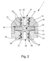
- the Fig. 2 shows a section through a closure element 1 according to a first embodiment.
- first cylinder member 11 and the second cylinder member 12 are arranged in alignment with each other and in the installed state, in particular, an extension of the inner conductor.
- the support member 13 Between the two is the support member 13, in the middle of which there is an opening 14 and to which the two cylinder member 11, 12 are arranged mirror-symmetrically.
- the cylinder elements 11, 12 extend here along the longitudinal axis of the closure element. 1
- impedance matching components 15 On the support member 13 are two impedance matching components 15, which serve the impedance matching of outer and inner conductors.
- the carrier element 13 is located within a cup element 16, which has a continuous recess 17 and an adjoining interior 18.
- the interior space 18 is designed essentially as a circular hollow cylinder, wherein the impedance matching components 15 are located between the bottom of the cup element 16 and the carrier element 13.
- the impedance matching components 15 are thus also arranged laterally to the longitudinal axis of the closure element 1.
- the cup element 16 is covered or closed by a plug element 19 which has a recess 20 for the second cylinder element 12 and which is inserted in the cup element 16 via a central section 21.
- a support portion 22 Adjacent to the central portion 21, a support portion 22 is provided, whose outer diameter corresponds to the outer diameter of the adjoining him cup member 16 and therefore terminates flush with it.
- the plug element 19 is welded to the cup element 16 by means of laser welding. Therefore, the end element 1 forms a compact and self-contained unit, which only has to be introduced into the conductor device of a level gauge.
- a blind hole 23 is provided, each having an internal thread here.
- both cylinder elements 11, 12 each have two circular recesses 24 on their sides, in each of which an O-ring is provided as a sealing element 25.
- the cylinder members 11, 12 are made of steel - or generally of an electrically conductive material - and the cup member 16 and the plug member 19 are each made of a polyetheretherketone (PEEK) as an example of an electrically insulating material.
- PEEK polyetheretherketone
- Fig. 3 a further variant of the closure element 1 is shown, which is very similar to that in the Fig. 2 variant is shown. Therefore, the description of the identical elements is omitted.
- the cylinder elements 11, 12 are here free of lateral recesses and are instead each surrounded by a holding element 26 and connected thereto by laser welding.
- the holding elements 26 have inside a continuous circular cylindrical shape and have on the outside an alternating structure of projections and recesses. In this case, the holding elements 26 are configured rotationally symmetrical and inserted into the cup element 16 or the plug element 19, respectively.
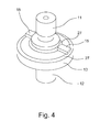
- the Fig. 4 shows the two cylinder element 11, 12 and the support member 13 of the end element 1 of Fig. 3 ,
- the annular carrier element 13 comprises at the outer and the inner boundary each have a contact surface 27, with which the two impedance matching components 15 are electrically connected.
- a terminating element 1 is connected to a conductor device 2.
- a pin member 28 which serves for electrical contacting of the inner conductor 5.
- a fastening element 29 is provided in the form of a screw, with a fixing element 30 in the form of a bar between the closing element 1 and the fastening element 29.
- the fixing member 30 extends laterally to the outer conductor 4, where two other fasteners 29 realize a fixation.
- the two cylinder elements 11, 12 are in the illustrated variant a Vermotherning the inner conductor 5, wherein the impedance matching components are outside this extension and here even perpendicular to the longitudinal axis.
Landscapes
- Physics & Mathematics (AREA)
- Electromagnetism (AREA)
- Thermal Sciences (AREA)
- Fluid Mechanics (AREA)
- General Physics & Mathematics (AREA)
- Engineering & Computer Science (AREA)
- Computer Networks & Wireless Communication (AREA)
- Signal Processing (AREA)
- Measurement Of Levels Of Liquids Or Fluent Solid Materials (AREA)
- Measurement Of Resistance Or Impedance (AREA)
- Details Of Connecting Devices For Male And Female Coupling (AREA)
Abstract
Description
- Die Erfindung betrifft ein Abschlusselement für eine Leitervorrichtung eines nach dem Laufzeit-Verfahren arbeitenden Füllstandmessgeräts. Weiterhin betrifft die Erfindung ein nach dem Laufzeit-Verfahren arbeitendes Füllstandmessgerät mit einer mindestens aus einem Außenleiter und einem Innenleiter gebildeten Leitervorrichtung zum Führen von elektromagnetischen Signalen.
- Bei einem Füllstandmessgerät, das nach dem Laufzeit-Verfahren arbeitet, wird das sogenannte TDR-Messprinzip (Time Domain Reflectometry) angewendet, indem die Laufzeit von entlang einer Leitervorrichtung geführten elektromagnetischen Signalen ausgewertet wird. Die Signale werden dabei entlang der Leitervorrichtung - bzw. insbesondere entlang mindestens einem der zwei die Leitervorrichtung bildenden Leitern - in Richtung der Oberfläche des Mediums, dessen Füllstand ermittelt werden soll, ausgesandt. Treffen die Signale auf die Oberfläche des Mediums, so werden sie dort teilweise reflektiert. Aus der Laufzeit zwischen dem Aussenden und dem Empfang der reflektierten Signale lässt sich dann der Füllstand des Mediums ermitteln. Der große Vorteil des Führens der Mikrowellensignale besteht darin, dass sich ändernde Umgebungsbedingungen (z. B. steigender oder ein fallender Umgebungsdruck, steigende oder fallende Temperatur) die Messgenauigkeit nicht beeinträchtigen und dass zudem die Laufzeit des Signals unabhängig von der Dielektrizitätszahl des Mediums ist.
- Die Leiter verfügen zumeist über ein Befestigungsende, mit dem sie an einem Anschluss oder Flansch befestigt sind, und über ein freies, dem Medium zugewandtes Ende. Über den Anschluss sind die Leiter mit einer Elektronik verbunden, die die zu übertragenden Signale erzeugt und die reflektierten Signale empfängt und auswertet.
- Bei den beschriebenen Füllstandmessgeräten existieren sogenannte "Totzonen", die Füllstandbereiche des Mediums beschreiben, in denen eine Messung nicht oder nur mit großer Ungenauigkeit möglich ist. Die Ursache für die "Totzonen" liegt in Impedanzsprüngen der für die Leitung der Signale verwenden Leiteranordnung, die sich durch die mechanische Konstruktion oder durch geometrische Gegebenheiten einstellen.
- Dabei wird zwischen einer "obere Totzone" in dem Bereich, in dem die Leiteranordnung in den Behälter hineingeführt ist, und einer "unteren Totzone" am freien Ende unterschieden.
- Um der Problematik der oberen Totzone zu begegnen, ist es teilweise vorgesehen, dass die Leiteranordnung aus zwei Leitern besteht, wobei ein Leiter den anderen Leiter koaxial umgibt. Solche Koaxialleiter haben den Vorteil einer über ihren geometrischen Verlauf gleichbleibenden Impedanz. Zudem lassen sich solche Leiter auch im Allgemeinen leicht an die Impedanz der der Leiteranordnung nachgeschalteten Elektronik anpassen, die häufig bei 50 Ohm liegt.
- Für das freie Ende der Leitervorrichtung ist es im Stand der Technik bekannt, Impedanzanpassungskomponenten, Abschlusswiderstände oder aus unterschiedlichen elektrischen Bauteilen - Widerstände, Kondensatoren, Spulen usw. - bestehende Impedanzanpassungenetzwerke vorzusehen. Hingewiesen sei beispielsweise auf die
EP 2 711 673 A1 , dieDE 100 43 838 A1 oder dieEP 2 154 496 A1 . Insbesondere in derEP 2 711 673 A1 ist vorgesehen, dass ein Innenleiter durch ein Endstück verlängert wird und dass sich der Abschlusswiderstand in dem als Leiter dienenden Endstück befindet. - Die Elemente zur Impedanzanpassung befinden sich dabei im Bereich des freien Endes der Leitervorrichtung und sind daher auch den Prozessbedingungen ausgesetzt.
- Der Erfindung liegt daher die Aufgabe zugrunde, ein Abschlusselement vorzuschlagen, das eine Alternative zum Stand der Technik darstellt.
- Das erfindungsgemäße Abschlusselement, bei dem die zuvor hergeleitete und aufgezeigte Aufgabe gelöst ist, ist zunächst und im Wesentlichen dadurch gekennzeichnet, dass zwischen einem ersten Zylinderelement und einem zweiten Zylinderelement mindestens ein Trägerelement angeordnet ist und dass auf dem Trägerelement mindestens eine Impedanzanpassungskomponente angeordnet ist.
- Das erste und das zweite Zylinderelement sind im Wesentlichen Zylinderförmig ausgestaltet, wobei der Grundquerschnitt z. B. ein Kreis oder ein Polygon ist. Die Seite mindestens eines Zylinderelements ist in einer Ausgestaltung mit Aussparungen und/oder Ausstülpungen versehen. Insgesamt ergibt sich jedoch ein zylinderartiger Gesamteindruck, wobei Zylinder allgemein derartig verstanden werden kann, dass die Höhe größer als die Erstreckung der Grundfläche ist. In einer Ausgestaltung verfügt mindestens ein Zylinderelement an mindestens einer Stirnseite über einen Fuß mit einem größeren oder kleineren Außenumfang als der Zylinder, der das entsprechende Zylinderelement beschreibt.
- In einer Ausgestaltung sind/ist das erste und/oder das zweite Zylinderelement elektrisch leitfähig. In einer Ausgestaltung sind das erste und das zweite Zylinderelement elektrisch leitend miteinander verbunden. Ist entsprechend wenigstens das erste Zylinderelement elektrisch leitend mit einem Leiter der Leitervorrichtung verbunden, so werden die elektromagnetischen Signale von dem Leiter auch über die zwei Zylinderelemente übertragen. Alternativ ist nur ein Zylinderelement mit einem Leiter der Leitervorrichtung verbunden.
- Stellen die zwei Zylinderelemente im verbauten Zustand eine Verlängerung oder eine Art Endstück des Innenleiters dar, so befindet sich die mindestens eine Impedanzanpassungskomponente auf dem Trägerelement außerhalb dieser Verlängerung und insbesondere auch seitlich zur Längsachse des Innenleiters.
- In einer Ausgestaltung ist das Trägerelement als Leiterplatte ausgeführt und weist in einer weiteren Ausgestaltung wenigstens eine Leiterplatte auf.
- Die Impedanzanpassungskomponente ist in einer Ausgestaltung zumindest ein elektrisches Bauteil und bildet in einer weiteren Ausgestaltung einen Teil eines Anpassungsnetzwerkes.
- Eine Ausgestaltung besteht darin, dass ein Becherelement vorgesehen ist, dass das Becherelement eine Aussparung zur zumindest teilweisen Aufnahme des ersten Zylinderelements aufweist, dass das Becherelement über einen sich an die Aussparung anschließenden Innenraum mit einem Innenumfang verfügt und dass das Trägerelement in dem Innenraum des Becherelements angeordnet ist.
- In einer Ausgestaltung ist das Becherelement rotationssymmetrisch ausgestaltet. In einer weiteren Ausgestaltung verfügt das Becherelement über eine durchgehende Aussparung. In einer anderen Ausgestaltung ist der Innenraum des Becherelements im Wesentlichen kreiszylindrischen ausgestaltet.
- In einer Ausgestaltung ist ein Stopfenelement vorgesehen. Das Stopfenelement weist eine Aussparung zur zumindest teilweisen Aufnahme des zweiten Zylinderelements auf.
- In einer Ausgestaltung sind das Becherelement und das Stopfenelement fest miteinander verbunden. Dies erfolgt beispielsweise durch Schweißen, Kleben oder Verschrauben. Dabei wird ein form- und/oder kraftschlüssige Verbindung erzeugt.
- Sind Becher- und Stopfenelement fest miteinander verbunden, so schützen sie das Trägerelement und insbesondere die mindestens eine Impedanzanpassungskomponente. Für die Verbindung zwischen der Impedanzanpassungskomponente und den Leitern der Leitervorrichtung sind passende Strukturen vorzusehen.
- Weiterhin ergibt sich insgesamt ein kompaktes Abschlusselement, das fertig montiert werden kann und dann nur noch mit der Leitervorrichtung verbunden bzw. fixiert werden muss. Daher wird die Herstellung eines Füllstandmessgerätes deutlich vereinfacht.
- In einer Ausgestaltung verfügt das Stopfenelement über einen im Innenraum des Becherelements angeordneten Zentralabschnitt. In einer Ausgestaltung ist das Stopfenelement rotationssymmetrisch ausgeführt. In einer weiteren Ausgestaltung verfügt das Stopfenelement über eine durchgehende Aussparung. In einer weiteren Ausgestaltung weist das Stopfenelement einen Auflageabschnitt auf, wobei ein Außenumfang des Auflageabschnitts größer als der Innenumfang des Innenraums des Becherelements ist. In einer Ausgestaltung grenzt der Auflageabschnitt an den Zentralabschnitt an.
- In einer Ausgestaltung ist die Impedanzanpassungskomponente auf der von dem Stopfenelement abgewandten Seite des Trägerelements angeordnet. Dadurch befindet sich die Impedanzanpassungskomponente zwischen dem Boden des Becherelements und dem Trägerelement. Oberhalb des Trägerelements befindet sich zudem noch das Stopfenelement. Die Impedanzanpassungskomponente befindet sich vorzugsweise außerhalb der Zylinderelemente und überdies vorzugsweise bedingt durch die Ausgestaltung und Anordnung des Trägerelements seitlich zu den Zylinderelementen angeordnet.
- In einer Ausgestaltung ist vorgesehen, dass das erste Zylinderelement mindestens eine Sacklochbohrung aufweist. In einer alternativen oder ergänzenden Ausgestaltung ist vorgesehen, dass das zweite Zylinderelement mindestens eine Sacklochbohrung aufweist.
- Eine Ausgestaltung besteht darin, dass zwischen dem ersten Zylinderelement und dem Becherelement eine Aussparung für mindestens ein Dichtelement vorgesehen ist. Bei dem Dichtelement handelt es sich beispielweise um einen O-Ring. Eine ergänzende oder alternative Ausgestaltung besteht darin, dass zwischen dem zweiten Zylinderelement und dem Stopfenelement mindestens eine Aussparung für mindestens ein Dichtelement vorgesehen ist.
- Bei den beiden Ausgestaltungen ist jeweils mindestens eine Aussparung zur Aufnahme mindestens eines Dichtelements vorgesehen. Dabei wird durch das Dichtelement der Übergang zwischen einem Zylinderelement und dem jeweils umgebenden Bauteil - also Becherelement bzw. Stopfenelement - abgedichtet.
- In einer Ausgestaltung sind das erste Zylinderelement und das zweite Zylinderelement zueinander fluchtend und spiegelsymmetrisch zum Trägerelement angeordnet.
- Gemäß einer weiteren Lehre bezieht sich die Erfindung auf ein nach dem Laufzeit-Verfahren arbeitendes Füllstandmessgerät mit einer mindestens aus einem Außenleiter und einem Innenleiter gebildeten Leitervorrichtung zum Führen von elektromagnetischen Signalen, das zumindest dadurch gekennzeichnet ist, dass an einem freien Ende der Leitervorrichtung ein Abschlusselement nach einem der oben ausgeführten Ausgestaltungen angeordnet ist.
- In einer Ausgestaltung ist vorgesehen, dass das erste Zylinderelement über ein Stiftelement elektrisch mit dem Innenleiter kontaktiert ist. Weiterhin ist das zweite Zylinderelement über ein Befestigungselement mit einem Fixierelement verbunden ist. Zudem ist das Fixierelement über mindestens ein weiteres Befestigungselement mit dem Außenleiter verbunden. Für die Impedanzanpassung ist schließlich die Impedanzanpassungskomponente elektrisch mit dem Innenleiter und dem Außenleiter kontaktiert.
- In einer Ausgestaltung ist das Fixierelement über zwei Befestigungselemente, bei denen es sich beispielsweise um Schrauben handelt, mit dem Außenleiter verbunden.
- Das Fixierelement ist in einer Ausgestaltung streifen- oder balkenähnlich ausgestaltet und ist alternativ im Wesentlichen tellerartig ausgeführt.
- In einer Ausgestaltung ist der Außenleiter im Bereich des freien Endes zumindest teilweise in Richtung des Abschlusselements geneigt.
- Im Einzelnen gibt es eine Vielzahl von Möglichkeiten, das erfindungsgemäße Abschlusselement und das erfindungsgemäße Füllstandmessgerät auszugestalten und weiterzubilden. Dazu wird verwiesen einerseits auf die den Patentansprüchen 1 und 9 nachgeordneten Patentansprüche, andererseits auf die folgende Beschreibung von Ausführungsbeispielen in Verbindung mit der Zeichnung. In der Zeichnung zeigen
- Fig. 1
- einen Schnitt durch eine schematische Darstellung eines Füllstandmessgerätes,
- Fig. 2
- einen Schnitt durch ein schematisch dargestelltes Abschlusselement in einer ersten Variante,
- Fig. 3
- einen Schnitt durch ein Abschlusselement in einer zweiten Variante,
- Fig. 4
- eine räumliche Darstellung eines Teils des in der
Fig. 3 dargestellten Abschlusselements und - Fig. 5
- einen Schnitt durch einen vergrößerten Ausschnitt eines Füllstandmessgerätes.
- In der
Fig. 1 ist ein Abschlusselement 1 für die Leitervorrichtung 2 eines Füllstandmessgeräts 3 dargestellt. - Die Füllstandmessung erfolgt durch die Auswertung der Laufzeit von elektromagnetischen Signalen, die sich entlang der Leitervorrichtung 2 ausbreiten. Dabei umgibt ein Außenleiter 4 koaxial einen Innenleiter 5.
- In dem Außenleiter 4 sind Löcher 6 vorhanden, durch die das Medium in den Hohlraum 7 um den Innenleiter 5 herum eindringen kann.
- In der Anwendung ist üblicherweise das freie Ende 8 dem - hier nicht dargestellten - Medium zugewandt. An dem gegenüberliegenden Befestigungsende 9 ist ein Anschluss 10 zur Befestigung beispielsweise an der Wandung des das Medium umfassenden Behälters vorgesehen.
- Die
Fig. 2 zeigt einen Schnitt durch ein Abschlusselement 1 gemäß einer ersten Ausgestaltung. - Mittig sind das erste Zylinderelement 11 und das zweite Zylinderelement 12 fluchtend zueinander angeordnet und stellen im eingebauten Zustand insbesondere eine Verlängerung des Innenleiters dar. Zwischen beiden befindet sich das Trägerelement 13, in dessen Mitte eine Öffnung 14 vorhanden ist und zu dem die zwei Zylinderelement 11, 12 spiegelsymmetrisch angeordnet sind. Die Zylinderelemente 11, 12 erstrecken sich hier längs der Längsachse des Abschlusselements 1.
- Auf dem Trägerelement 13 befinden sich zwei Impedanzanpassungskomponenten 15, die der Impedanzanpassung von Außen- und Innenleiter dienen.
- Das Trägerelement 13 befindet sich innerhalb eines Becherelements 16, das über eine durchgehende Aussparung 17 sowie einen sich daran anschließenden Innenraum 18 verfügt. Der Innenraum 18 ist dabei im Wesentlichen als kreisförmiger Hohlzylinder ausgestaltet, wobei sich zwischen dem Boden des Becherelements 16 und dem Trägerelement 13 die Impedanzanpassungskomponenten 15 befinden. Die Impedanzanpassungskomponenten 15 sind damit auch seitlich zur Längsachse des Abschlusselements 1 angeordnet.
- Abgedeckt bzw. verschlossen wird das Becherelement 16 durch ein Stopfenelement 19, das über eine Aussparung 20 für das zweite Zylinderelement 12 verfügt und das über einen Zentralabschnitt 21 in dem Becherelement 16 steckt.
- Angrenzend an den Zentralabschnitt 21 ist ein Auflageabschnitt 22 vorgesehen, dessen Außendurchmesser dem Außendurchmesser des an ihn angrenzenden Becherelements 16 entspricht und daher bündig mit ihm abschließt.
- Im Bereich des Auflageabschnitts 22 ist das Stopfenelement 19 mit dem Becherelement 16 mittels Laserschweißung verschweißt. Daher bildet das Abschlusselement 1 eine kompakte und in sich geschlossene Einheit, die nur noch in die Leitervorrichtung eines Füllstandmessgeräts eingebracht werden muss.
- An den Auflageabschnitt 22 des Stopfenelements 19 grenzt hier noch eine Erhöhung an.
- Mittig in den Zylinderelementen 11, 12 ist jeweils eine Sacklochbohrung 23 vorgesehen, die hier jeweils über ein Innengewinde verfügen.
- Um den Übergang zwischen den Zylinderelementen 11, 12 und dem Becherelement 16 bzw. dem Stopfenelement 19 abzudichten, verfügen beide Zylinderelemente 11, 12 an ihren Seiten jeweils über zwei kreisförmig umlaufende Aussparungen 24, in denen jeweils ein O-Ring als Dichtelement 25 vorgesehen ist.
- In Bezug auf die Materialauswahl bestehen die Zylinderelemente 11, 12 hier aus Stahl - bzw. allgemein aus einem elektrisch leitfähigen Material - und das Becherelement 16 und das Stopfenelement 19 jeweils aus einem Polyetheretherketon (PEEK) als einem Beispiel für ein elektrisch isolierendes Material.
- In der
Fig. 3 ist eine weitere Variante des Abschlusselements 1 dargestellt, das sehr ähnlich der in derFig. 2 dargestellten Variante ist. Daher wird auf die Beschreibung der identischen Elemente verzichtet. - Die Zylinderelemente 11, 12 sind hier frei von seitlichen Aussparungen und sind stattdessen jeweils von einem Halteelement 26 umgeben und mit diesem durch Laserschweißung verbunden. Die Halteelemente 26 haben innen eine durchgehend kreiszylindrische Form und verfügen außen über eine sich abwechselnde Struktur aus Vorsprüngen und Aussparungen. Dabei sind die Halteelemente 26 rotationssymmetrisch ausgestaltet und passend in das Becherelement 16 bzw. das Stopfenelement 19 eingefügt.
- Die
Fig. 4 zeigt die zwei Zylinderelement 11, 12 und das Trägerelement 13 des Abschlusselements 1 derFig. 3 . - Zu erkennen ist hier am ersten Zylinderelement 11 der Fuß unterhalb der Verengung, die sich an den hier glatt verlaufenden Außenzylinderabsatz anschließt.
- Das ringförmige Trägerelement 13 umfasst an der Außen- und der Innenberandung jeweils eine Kontaktfläche 27, mit der die beiden Impedanzanpassungskomponenten 15 elektrisch leitend verbunden sind.
- In der
Fig. 5 ist dargestellt, wie ein Abschlusselement 1 mit einer Leitervorrichtung 2 verbunden ist. - In der Sacklochbohrung 23 des ersten Zylinderelements 11 befindet sich ein Stiftelement 28, das einer elektrischen Kontaktierung des Innenleiters 5 dient.
- In der Sacklochbohrung 23 des zweiten Zylinderelements 12 ist ein Befestigungselement 29 in Form einer Schraube vorgesehen, wobei sich zwischen dem Abschlusselement 1 und dem Befestigungselement 29 ein Fixierelement 30 in Form eines Balkens befindet. Das Fixierelement 30 erstreckt sich seitlich bis zum Außenleiter 4, wo zwei weitere Befestigungselemente 29 eine Fixierung realisieren.
- Die zwei Zylinderelement 11, 12 sind in der dargestellten Variante eine Verlängening des Innenleiters 5, wobei sich die Impedanzanpassungskomponenten außerhalb dieser Verlängerung und hier sogar senkrecht zur Längsachse befinden.
Claims (10)
- Abschlusselement (1) für eine Leitervorrichtung (2) eines nach dem Laufzeit-Verfahren arbeitenden Füllstandmessgeräts (3),
dadurch gekennzeichnet,
dass zwischen einem - insbesondere elektrisch leitfähigen - ersten Zylinderelement (11) und einem - insbesondere elektrisch leitfähigen - zweiten Zylinderelement (12) mindestens ein - insbesondere als Leiterplatte ausgestaltetes oder eine Leiterplatte aufweisendes - Trägerelement (13) angeordnet ist und dass auf dem Trägerelement (13) mindestens eine Impedanzanpassungskomponente (15) angeordnet ist. - Abschlusselement (1) nach Anspruch 1, dadurch gekennzeichnet, dass ein - insbesondere rotationssymmetrisches - Becherelement (16) vorgesehen ist, dass das Becherelement (16) eine - insbesondere durchgehende - Aussparung (17) zur zumindest teilweisen Aufnahme des ersten Zylinderelements (11) aufweist, dass das Becherelement (16) über einen sich an die - insbesondere durchgehende - Aussparung (17) anschließenden - insbesondere im Wesentlichen kreiszylindrischen - Innenraum (18) mit einem Innenumfang verfügt und dass das Trägerelement (13) in dem Innenraum (18) des Becherelements (16) angeordnet ist.
- Abschlusselement (1) nach Anspruch 2, dadurch gekennzeichnet, dass ein - insbesondere rotationssymmetrisches - Stopfenelement (19) vorgesehen ist und dass das Stopfenelement (19) eine - insbesondere durchgehende - Aussparung (20) zur zumindest teilweisen Aufnahme des zweiten Zylinderelements (12) aufweist.
- Abschlusselement (1) nach Anspruch 3, dadurch gekennzeichnet, dass das Stopfenelement (19) einen im Innenraum (18) des Becherelements (16) angeordneten Zentralabschnitt (21) aufweist und dass das Stopfenelement (19) einen Auflageabschnitt (22) aufweist, wobei ein Außenumfang des Auflageabschnitts (22) größer als der Innenumfang des Innenraums (18) des Becherelements (16) ist.
- Abschlusselement (1) nach Anspruch 3 oder 4, dadurch gekennzeichnet, dass zwischen dem ersten Zylinderelement (11) und dem Becherelement (16) und/oder zwischen dem zweiten Zylinderelement (12) und dem Stopfenelement (19) mindestens eine Aussparung (24) für mindestens ein Dichtelement (25) vorgesehen ist.
- Abschlusselement (1) nach einem der Ansprüche 3 bis 5, dadurch gekennzeichnet, dass die Impedanzanpassungskomponente (15) auf der von dem Stopfenelement (19) abgewandten Seite des Trägerelements (13) angeordnet ist.
- Abschlusselement (1) nach einem der Ansprüche 1 bis 6, dadurch gekennzeichnet, dass das erste Zylinderelement (11) und/oder das zweite Zylinderelement (12) mindestens eine Sacklochbohrung (23) aufweiseuaufweist.
- Abschlusselement (1) nach einem der Ansprüche 1 bis 7, dadurch gekennzeichnet, dass das erste Zylinderelement (11) und das zweite Zylinderelement (12) zueinander fluchtend und spiegelsymmetrisch zum Trägerelement (13) angeordnet sind.
- Nach dem Laufzeit-Verfahren arbeitendes Füllstandmessgerät (3) mit einer mindestens aus einem Außenleiter (4) und einem Innenleiter (5) gebildeten Leitervorrichtung (2) zum Führen von elektromagnetischen Signalen,
dadurch gekennzeichnet,
dass an einem freien Ende (8) der Leitervorrichtung (2) ein Abschlusselement (1) nach einem der Ansprüche 1 bis 8 angeordnet ist. - Füllstandmessgerät (3) nach Anspruch 9, dadurch gekennzeichnet, dass das erste Zylinderelement (11) über ein Stiftelement (28) elektrisch mit dem Innenleiter (5) kontaktiert ist, dass das zweite Zylinderelement (12) über ein Befestigungselement (29) mit einem Fixierelement (30) verbunden ist, dass das Fixierelement (30) über mindestens ein weiteres Befestigungselement (29) mit dem Außenleiter (4) verbunden ist und dass die Impedanzanpassungskomponente (15) elektrisch mit dem Innenleiter (5) und dem Außenleiter (4) kontaktiert ist.
Applications Claiming Priority (1)
| Application Number | Priority Date | Filing Date | Title |
|---|---|---|---|
| DE102014107393.2A DE102014107393B4 (de) | 2014-05-26 | 2014-05-26 | Abschlusselement für Füllstandmessgerät und Füllstandmessgerät |
Publications (2)
| Publication Number | Publication Date |
|---|---|
| EP2950059A1 true EP2950059A1 (de) | 2015-12-02 |
| EP2950059B1 EP2950059B1 (de) | 2019-07-10 |
Family
ID=53199847
Family Applications (1)
| Application Number | Title | Priority Date | Filing Date |
|---|---|---|---|
| EP15168974.2A Active EP2950059B1 (de) | 2014-05-26 | 2015-05-22 | Abschlusselement für füllstandmessgerät und füllstandmessgerät |
Country Status (5)
| Country | Link |
|---|---|
| US (1) | US9698456B2 (de) |
| EP (1) | EP2950059B1 (de) |
| CN (1) | CN105203182B (de) |
| DE (1) | DE102014107393B4 (de) |
| DK (1) | DK2950059T3 (de) |
Families Citing this family (2)
| Publication number | Priority date | Publication date | Assignee | Title |
|---|---|---|---|---|
| US10281314B2 (en) * | 2016-03-30 | 2019-05-07 | Hella Kgaa Hueck & Co. | Device for measuring a fill level of a liquid |
| DE102017102587A1 (de) * | 2017-02-09 | 2018-08-09 | Krohne Messtechnik Gmbh | Füllstandsschalter und Verfahren zur Bestimmung eines Grenzstandes eines Mediums in einem Behälter |
Citations (5)
| Publication number | Priority date | Publication date | Assignee | Title |
|---|---|---|---|---|
| US4035748A (en) * | 1974-09-26 | 1977-07-12 | Bunker Ramo Corporation | Coaxial impedance transducer pad |
| DE10043838A1 (de) | 2000-09-06 | 2002-04-04 | Grieshaber Vega Kg | Füllstandsmeßvorrichtung |
| US20100007441A1 (en) * | 2008-07-11 | 2010-01-14 | Fujitsu Limited | Coaxial connector having a dielectric material for impedance matching |
| EP2154496A1 (de) | 2008-08-15 | 2010-02-17 | Sick Ag | TDR-Sensor und -Messverfahren |
| EP2711673A1 (de) | 2012-09-25 | 2014-03-26 | VEGA Grieshaber KG | Koaxialsonde mit Abschlusswiderstand |
Family Cites Families (17)
| Publication number | Priority date | Publication date | Assignee | Title |
|---|---|---|---|---|
| JPS6129775A (ja) * | 1984-07-20 | 1986-02-10 | Mitsubishi Electric Corp | 高周波磁場発生・検出器 |
| IT1187521B (it) * | 1985-01-09 | 1987-12-23 | Zanussi Zeltron Inst | Procedimento di misurazione del livello di un liquido tramite onde elastiche e dispositivo effettuante tale procedimento |
| EP0201298A3 (de) | 1985-05-03 | 1988-08-03 | Sheffer Collet Company | Automatischer richtender ersetzbarer Werkstückträger |
| US5554936A (en) * | 1994-12-01 | 1996-09-10 | Mohr; Charles L. | Mixed fluid time domain reflectometry sensors |
| GB2306003B (en) * | 1995-10-02 | 1999-09-29 | Federal Ind Ind Group Inc | Level detector for solids |
| US6662648B2 (en) | 2000-09-06 | 2003-12-16 | Vega Grieshaber Kg | Filling level measuring device |
| US6993967B2 (en) * | 2002-07-12 | 2006-02-07 | Ti Group Automotive Systems, L.L.C. | Fluid level sensor |
| US7255002B2 (en) * | 2005-04-07 | 2007-08-14 | Rosemount, Inc. | Tank seal for guided wave radar level measurement |
| DE102007030847A1 (de) * | 2007-07-03 | 2009-01-15 | Sick Ag | Sensor nach dem TDR-Prinzip mit einer koaxialen Sonde und Herstellungsverfahren dafür |
| DE202008006344U1 (de) * | 2008-05-08 | 2008-10-16 | Sensorentechnologie Gettorf Gmbh | Abschlussteil |
| US7636059B1 (en) * | 2008-06-04 | 2009-12-22 | Rosemount Tank Radar Ab | Impedance matched guided wave radar level gauge system |
| DE102008057755B4 (de) * | 2008-11-17 | 2015-12-17 | Krohne Ag | Magnetisch-induktives Durchflußmeßgerät |
| US8218396B2 (en) * | 2010-03-16 | 2012-07-10 | Ut-Battelle, Llc | Torsional ultrasonic wave based level measurement system |
| DE102012003373B4 (de) * | 2012-02-22 | 2018-11-22 | Krohne Messtechnik Gmbh | Verfahren zur Überwachung und Verfahren zum Betreiben eines nach dem Radar-Prinzip arbeitenden Füllstandmesssystems und entsprechendes Füllstandmesssystem |
| US9212942B2 (en) * | 2012-07-04 | 2015-12-15 | Vega Grieshaber Kg | Waveguide coupling, high-frequency module, fill-level radar and use |
| CN202793306U (zh) * | 2012-09-11 | 2013-03-13 | 北京经纬恒润科技有限公司 | 一种高度测量装置 |
| JP6097119B2 (ja) * | 2013-03-29 | 2017-03-15 | 東京計器株式会社 | 電波レベル計 |
-
2014
- 2014-05-26 DE DE102014107393.2A patent/DE102014107393B4/de active Active
-
2015
- 2015-05-22 DK DK15168974.2T patent/DK2950059T3/da active
- 2015-05-22 US US14/719,712 patent/US9698456B2/en active Active
- 2015-05-22 EP EP15168974.2A patent/EP2950059B1/de active Active
- 2015-05-26 CN CN201510513919.5A patent/CN105203182B/zh active Active
Patent Citations (5)
| Publication number | Priority date | Publication date | Assignee | Title |
|---|---|---|---|---|
| US4035748A (en) * | 1974-09-26 | 1977-07-12 | Bunker Ramo Corporation | Coaxial impedance transducer pad |
| DE10043838A1 (de) | 2000-09-06 | 2002-04-04 | Grieshaber Vega Kg | Füllstandsmeßvorrichtung |
| US20100007441A1 (en) * | 2008-07-11 | 2010-01-14 | Fujitsu Limited | Coaxial connector having a dielectric material for impedance matching |
| EP2154496A1 (de) | 2008-08-15 | 2010-02-17 | Sick Ag | TDR-Sensor und -Messverfahren |
| EP2711673A1 (de) | 2012-09-25 | 2014-03-26 | VEGA Grieshaber KG | Koaxialsonde mit Abschlusswiderstand |
Also Published As
| Publication number | Publication date |
|---|---|
| US9698456B2 (en) | 2017-07-04 |
| US20150340750A1 (en) | 2015-11-26 |
| DK2950059T3 (da) | 2019-10-07 |
| CN105203182B (zh) | 2021-03-09 |
| DE102014107393A1 (de) | 2015-11-26 |
| CN105203182A (zh) | 2015-12-30 |
| EP2950059B1 (de) | 2019-07-10 |
| DE102014107393B4 (de) | 2020-04-23 |
Similar Documents
| Publication | Publication Date | Title |
|---|---|---|
| WO2008055758A1 (de) | Messsonde für ein messgerät | |
| DE102013202090A1 (de) | Druckmessgerät | |
| EP3649392B1 (de) | Messrohr zur bestimmung und/oder überwachung zumindest einer prozessgrösse eines mediums | |
| EP4174450B1 (de) | Magnetisch-induktives durchflussmessgerät | |
| DE102004032965B4 (de) | Vorrichtung zum Ausrichten und Zentrieren eines stab- oder seilförmigen Oberflächenwellenleiters eines Feldgerätes | |
| EP2950059B1 (de) | Abschlusselement für füllstandmessgerät und füllstandmessgerät | |
| WO2016012337A1 (de) | Magnetisch-induktives durchflussmessgerät | |
| DE102006045940A1 (de) | Abstandshalter für Koaxialinnenleiter | |
| WO2019038266A1 (de) | Modulares feldgerät | |
| DE102018104843A1 (de) | Erdungsanschlusselement zur Abschirmung von in Kunststoffgehäusen angeordneten elektrischen Komponenten sowie Verfahren zu seinem Einbau | |
| DE102012112318B4 (de) | Vorrichtung zum Ausrichten und Zentrieren eines Oberflächenwellenleiters eines Feldgerätes | |
| DE102011085128A1 (de) | Vorrichtung zur Bestimmung und/oder Überwachung mindestens einer Prozessgröße | |
| EP3258224B1 (de) | Abstandhalter zum halten eines abstandes zwischen einem stabförmigen innenleiter und einem aussenleiter einer füllstand-messsonde | |
| DE102004061357A1 (de) | Vorrichtung zur Überwachung eines Behälterfüllstandes | |
| EP3857082B1 (de) | Wälzkörper mit integrierter elektronik zur verwendung in einem wälzlager | |
| EP3391468B1 (de) | Kuppler zwischen einem koaxialen verbinder und einem koaxialkabel | |
| DE10219880A1 (de) | Rotationssensor | |
| DE102004062314A1 (de) | Füllstands-Messvorrichtung | |
| EP4385292A1 (de) | Transmittergehäuse eines feldgeräts | |
| WO2017220258A1 (de) | Kontaktsystem, leiterplattenanordnung und steckeranordnung | |
| EP3029430A1 (de) | Sensor mit Nutenstein | |
| WO2003048695A1 (de) | Zentriervorrichtung für eine stab- oder seilförmige sonde | |
| DE102009036527A1 (de) | Nach dem Radar-Prinzip arbeitendes Füllstandsmessgerät | |
| DE19831894C2 (de) | Magnetisch induktiver Durchflussmesser | |
| EP3853621B1 (de) | Formteil zur aufnahme eines c-förmigen magnetfeldkonzentrationselements, magnetfeldkonzentrationsvorrichtung und stromrichter |
Legal Events
| Date | Code | Title | Description |
|---|---|---|---|
| AK | Designated contracting states |
Kind code of ref document: A1 Designated state(s): AL AT BE BG CH CY CZ DE DK EE ES FI FR GB GR HR HU IE IS IT LI LT LU LV MC MK MT NL NO PL PT RO RS SE SI SK SM TR |
|
| AX | Request for extension of the european patent |
Extension state: BA ME |
|
| PUAI | Public reference made under article 153(3) epc to a published international application that has entered the european phase |
Free format text: ORIGINAL CODE: 0009012 |
|
| 17P | Request for examination filed |
Effective date: 20160602 |
|
| RBV | Designated contracting states (corrected) |
Designated state(s): AL AT BE BG CH CY CZ DE DK EE ES FI FR GB GR HR HU IE IS IT LI LT LU LV MC MK MT NL NO PL PT RO RS SE SI SK SM TR |
|
| STAA | Information on the status of an ep patent application or granted ep patent |
Free format text: STATUS: EXAMINATION IS IN PROGRESS |
|
| 17Q | First examination report despatched |
Effective date: 20170818 |
|
| REG | Reference to a national code |
Ref country code: DE Ref legal event code: R079 Ref document number: 502015009571 Country of ref document: DE Free format text: PREVIOUS MAIN CLASS: G01F0023284000 Ipc: H03H0007380000 |
|
| GRAP | Despatch of communication of intention to grant a patent |
Free format text: ORIGINAL CODE: EPIDOSNIGR1 |
|
| STAA | Information on the status of an ep patent application or granted ep patent |
Free format text: STATUS: GRANT OF PATENT IS INTENDED |
|
| GRAS | Grant fee paid |
Free format text: ORIGINAL CODE: EPIDOSNIGR3 |
|
| RIC1 | Information provided on ipc code assigned before grant |
Ipc: H03H 7/38 20060101AFI20190207BHEP Ipc: H04B 3/52 20060101ALI20190207BHEP |
|
| INTG | Intention to grant announced |
Effective date: 20190228 |
|
| GRAA | (expected) grant |
Free format text: ORIGINAL CODE: 0009210 |
|
| STAA | Information on the status of an ep patent application or granted ep patent |
Free format text: STATUS: THE PATENT HAS BEEN GRANTED |
|
| AK | Designated contracting states |
Kind code of ref document: B1 Designated state(s): AL AT BE BG CH CY CZ DE DK EE ES FI FR GB GR HR HU IE IS IT LI LT LU LV MC MK MT NL NO PL PT RO RS SE SI SK SM TR |
|
| REG | Reference to a national code |
Ref country code: GB Ref legal event code: FG4D Free format text: NOT ENGLISH |
|
| REG | Reference to a national code |
Ref country code: CH Ref legal event code: EP Ref country code: AT Ref legal event code: REF Ref document number: 1154567 Country of ref document: AT Kind code of ref document: T Effective date: 20190715 |
|
| REG | Reference to a national code |
Ref country code: DE Ref legal event code: R096 Ref document number: 502015009571 Country of ref document: DE |
|
| REG | Reference to a national code |
Ref country code: IE Ref legal event code: FG4D Free format text: LANGUAGE OF EP DOCUMENT: GERMAN |
|
| REG | Reference to a national code |
Ref country code: DK Ref legal event code: T3 Effective date: 20191004 |
|
| REG | Reference to a national code |
Ref country code: NL Ref legal event code: MP Effective date: 20190710 |
|
| REG | Reference to a national code |
Ref country code: LT Ref legal event code: MG4D |
|
| PG25 | Lapsed in a contracting state [announced via postgrant information from national office to epo] |
Ref country code: PT Free format text: LAPSE BECAUSE OF FAILURE TO SUBMIT A TRANSLATION OF THE DESCRIPTION OR TO PAY THE FEE WITHIN THE PRESCRIBED TIME-LIMIT Effective date: 20191111 Ref country code: HR Free format text: LAPSE BECAUSE OF FAILURE TO SUBMIT A TRANSLATION OF THE DESCRIPTION OR TO PAY THE FEE WITHIN THE PRESCRIBED TIME-LIMIT Effective date: 20190710 Ref country code: SE Free format text: LAPSE BECAUSE OF FAILURE TO SUBMIT A TRANSLATION OF THE DESCRIPTION OR TO PAY THE FEE WITHIN THE PRESCRIBED TIME-LIMIT Effective date: 20190710 Ref country code: NO Free format text: LAPSE BECAUSE OF FAILURE TO SUBMIT A TRANSLATION OF THE DESCRIPTION OR TO PAY THE FEE WITHIN THE PRESCRIBED TIME-LIMIT Effective date: 20191010 Ref country code: FI Free format text: LAPSE BECAUSE OF FAILURE TO SUBMIT A TRANSLATION OF THE DESCRIPTION OR TO PAY THE FEE WITHIN THE PRESCRIBED TIME-LIMIT Effective date: 20190710 Ref country code: NL Free format text: LAPSE BECAUSE OF FAILURE TO SUBMIT A TRANSLATION OF THE DESCRIPTION OR TO PAY THE FEE WITHIN THE PRESCRIBED TIME-LIMIT Effective date: 20190710 Ref country code: BG Free format text: LAPSE BECAUSE OF FAILURE TO SUBMIT A TRANSLATION OF THE DESCRIPTION OR TO PAY THE FEE WITHIN THE PRESCRIBED TIME-LIMIT Effective date: 20191010 Ref country code: LT Free format text: LAPSE BECAUSE OF FAILURE TO SUBMIT A TRANSLATION OF THE DESCRIPTION OR TO PAY THE FEE WITHIN THE PRESCRIBED TIME-LIMIT Effective date: 20190710 |
|
| PG25 | Lapsed in a contracting state [announced via postgrant information from national office to epo] |
Ref country code: IS Free format text: LAPSE BECAUSE OF FAILURE TO SUBMIT A TRANSLATION OF THE DESCRIPTION OR TO PAY THE FEE WITHIN THE PRESCRIBED TIME-LIMIT Effective date: 20191110 Ref country code: RS Free format text: LAPSE BECAUSE OF FAILURE TO SUBMIT A TRANSLATION OF THE DESCRIPTION OR TO PAY THE FEE WITHIN THE PRESCRIBED TIME-LIMIT Effective date: 20190710 Ref country code: GR Free format text: LAPSE BECAUSE OF FAILURE TO SUBMIT A TRANSLATION OF THE DESCRIPTION OR TO PAY THE FEE WITHIN THE PRESCRIBED TIME-LIMIT Effective date: 20191011 Ref country code: AL Free format text: LAPSE BECAUSE OF FAILURE TO SUBMIT A TRANSLATION OF THE DESCRIPTION OR TO PAY THE FEE WITHIN THE PRESCRIBED TIME-LIMIT Effective date: 20190710 Ref country code: LV Free format text: LAPSE BECAUSE OF FAILURE TO SUBMIT A TRANSLATION OF THE DESCRIPTION OR TO PAY THE FEE WITHIN THE PRESCRIBED TIME-LIMIT Effective date: 20190710 Ref country code: ES Free format text: LAPSE BECAUSE OF FAILURE TO SUBMIT A TRANSLATION OF THE DESCRIPTION OR TO PAY THE FEE WITHIN THE PRESCRIBED TIME-LIMIT Effective date: 20190710 |
|
| PG25 | Lapsed in a contracting state [announced via postgrant information from national office to epo] |
Ref country code: TR Free format text: LAPSE BECAUSE OF FAILURE TO SUBMIT A TRANSLATION OF THE DESCRIPTION OR TO PAY THE FEE WITHIN THE PRESCRIBED TIME-LIMIT Effective date: 20190710 |
|
| PG25 | Lapsed in a contracting state [announced via postgrant information from national office to epo] |
Ref country code: PL Free format text: LAPSE BECAUSE OF FAILURE TO SUBMIT A TRANSLATION OF THE DESCRIPTION OR TO PAY THE FEE WITHIN THE PRESCRIBED TIME-LIMIT Effective date: 20190710 Ref country code: IT Free format text: LAPSE BECAUSE OF FAILURE TO SUBMIT A TRANSLATION OF THE DESCRIPTION OR TO PAY THE FEE WITHIN THE PRESCRIBED TIME-LIMIT Effective date: 20190710 Ref country code: RO Free format text: LAPSE BECAUSE OF FAILURE TO SUBMIT A TRANSLATION OF THE DESCRIPTION OR TO PAY THE FEE WITHIN THE PRESCRIBED TIME-LIMIT Effective date: 20190710 Ref country code: EE Free format text: LAPSE BECAUSE OF FAILURE TO SUBMIT A TRANSLATION OF THE DESCRIPTION OR TO PAY THE FEE WITHIN THE PRESCRIBED TIME-LIMIT Effective date: 20190710 |
|
| PG25 | Lapsed in a contracting state [announced via postgrant information from national office to epo] |
Ref country code: SM Free format text: LAPSE BECAUSE OF FAILURE TO SUBMIT A TRANSLATION OF THE DESCRIPTION OR TO PAY THE FEE WITHIN THE PRESCRIBED TIME-LIMIT Effective date: 20190710 Ref country code: IS Free format text: LAPSE BECAUSE OF FAILURE TO SUBMIT A TRANSLATION OF THE DESCRIPTION OR TO PAY THE FEE WITHIN THE PRESCRIBED TIME-LIMIT Effective date: 20200224 Ref country code: CZ Free format text: LAPSE BECAUSE OF FAILURE TO SUBMIT A TRANSLATION OF THE DESCRIPTION OR TO PAY THE FEE WITHIN THE PRESCRIBED TIME-LIMIT Effective date: 20190710 Ref country code: SK Free format text: LAPSE BECAUSE OF FAILURE TO SUBMIT A TRANSLATION OF THE DESCRIPTION OR TO PAY THE FEE WITHIN THE PRESCRIBED TIME-LIMIT Effective date: 20190710 |
|
| REG | Reference to a national code |
Ref country code: DE Ref legal event code: R097 Ref document number: 502015009571 Country of ref document: DE |
|
| PLBE | No opposition filed within time limit |
Free format text: ORIGINAL CODE: 0009261 |
|
| STAA | Information on the status of an ep patent application or granted ep patent |
Free format text: STATUS: NO OPPOSITION FILED WITHIN TIME LIMIT |
|
| PG2D | Information on lapse in contracting state deleted |
Ref country code: IS |
|
| 26N | No opposition filed |
Effective date: 20200603 |
|
| PG25 | Lapsed in a contracting state [announced via postgrant information from national office to epo] |
Ref country code: SI Free format text: LAPSE BECAUSE OF FAILURE TO SUBMIT A TRANSLATION OF THE DESCRIPTION OR TO PAY THE FEE WITHIN THE PRESCRIBED TIME-LIMIT Effective date: 20190710 |
|
| PG25 | Lapsed in a contracting state [announced via postgrant information from national office to epo] |
Ref country code: MC Free format text: LAPSE BECAUSE OF FAILURE TO SUBMIT A TRANSLATION OF THE DESCRIPTION OR TO PAY THE FEE WITHIN THE PRESCRIBED TIME-LIMIT Effective date: 20190710 |
|
| REG | Reference to a national code |
Ref country code: BE Ref legal event code: MM Effective date: 20200531 |
|
| PG25 | Lapsed in a contracting state [announced via postgrant information from national office to epo] |
Ref country code: LU Free format text: LAPSE BECAUSE OF NON-PAYMENT OF DUE FEES Effective date: 20200522 |
|
| PG25 | Lapsed in a contracting state [announced via postgrant information from national office to epo] |
Ref country code: IE Free format text: LAPSE BECAUSE OF NON-PAYMENT OF DUE FEES Effective date: 20200522 |
|
| PG25 | Lapsed in a contracting state [announced via postgrant information from national office to epo] |
Ref country code: BE Free format text: LAPSE BECAUSE OF NON-PAYMENT OF DUE FEES Effective date: 20200531 |
|
| REG | Reference to a national code |
Ref country code: AT Ref legal event code: MM01 Ref document number: 1154567 Country of ref document: AT Kind code of ref document: T Effective date: 20200522 |
|
| PG25 | Lapsed in a contracting state [announced via postgrant information from national office to epo] |
Ref country code: AT Free format text: LAPSE BECAUSE OF NON-PAYMENT OF DUE FEES Effective date: 20200522 |
|
| PG25 | Lapsed in a contracting state [announced via postgrant information from national office to epo] |
Ref country code: MT Free format text: LAPSE BECAUSE OF FAILURE TO SUBMIT A TRANSLATION OF THE DESCRIPTION OR TO PAY THE FEE WITHIN THE PRESCRIBED TIME-LIMIT Effective date: 20190710 Ref country code: CY Free format text: LAPSE BECAUSE OF FAILURE TO SUBMIT A TRANSLATION OF THE DESCRIPTION OR TO PAY THE FEE WITHIN THE PRESCRIBED TIME-LIMIT Effective date: 20190710 |
|
| PG25 | Lapsed in a contracting state [announced via postgrant information from national office to epo] |
Ref country code: MK Free format text: LAPSE BECAUSE OF FAILURE TO SUBMIT A TRANSLATION OF THE DESCRIPTION OR TO PAY THE FEE WITHIN THE PRESCRIBED TIME-LIMIT Effective date: 20190710 |
|
| P01 | Opt-out of the competence of the unified patent court (upc) registered |
Effective date: 20230607 |
|
| PGFP | Annual fee paid to national office [announced via postgrant information from national office to epo] |
Ref country code: GB Payment date: 20240627 Year of fee payment: 10 |
|
| PGFP | Annual fee paid to national office [announced via postgrant information from national office to epo] |
Ref country code: DK Payment date: 20250526 Year of fee payment: 11 |
|
| PGFP | Annual fee paid to national office [announced via postgrant information from national office to epo] |
Ref country code: FR Payment date: 20250528 Year of fee payment: 11 |
|
| PGFP | Annual fee paid to national office [announced via postgrant information from national office to epo] |
Ref country code: CH Payment date: 20250601 Year of fee payment: 11 |
|
| PGFP | Annual fee paid to national office [announced via postgrant information from national office to epo] |
Ref country code: DE Payment date: 20250717 Year of fee payment: 11 |
|
| GBPC | Gb: european patent ceased through non-payment of renewal fee |
Effective date: 20250522 |
|
| PG25 | Lapsed in a contracting state [announced via postgrant information from national office to epo] |
Ref country code: GB Free format text: LAPSE BECAUSE OF NON-PAYMENT OF DUE FEES Effective date: 20250522 |