EP2950004A1 - Mounting element for mounting a component of a household appliance - Google Patents
Mounting element for mounting a component of a household appliance Download PDFInfo
- Publication number
- EP2950004A1 EP2950004A1 EP15167453.8A EP15167453A EP2950004A1 EP 2950004 A1 EP2950004 A1 EP 2950004A1 EP 15167453 A EP15167453 A EP 15167453A EP 2950004 A1 EP2950004 A1 EP 2950004A1
- Authority
- EP
- European Patent Office
- Prior art keywords
- mounting element
- household appliance
- component
- opening
- mounting
- Prior art date
- Legal status (The legal status is an assumption and is not a legal conclusion. Google has not performed a legal analysis and makes no representation as to the accuracy of the status listed.)
- Withdrawn
Links
- 239000002184 metal Substances 0.000 claims abstract description 21
- 238000007789 sealing Methods 0.000 claims description 53
- 238000010438 heat treatment Methods 0.000 claims description 8
- 238000004891 communication Methods 0.000 claims description 3
- 235000013305 food Nutrition 0.000 claims description 3
- 238000003780 insertion Methods 0.000 description 10
- 230000037431 insertion Effects 0.000 description 10
- 239000000463 material Substances 0.000 description 4
- 238000004080 punching Methods 0.000 description 3
- 101001121408 Homo sapiens L-amino-acid oxidase Proteins 0.000 description 1
- 101000827703 Homo sapiens Polyphosphoinositide phosphatase Proteins 0.000 description 1
- 102100026388 L-amino-acid oxidase Human genes 0.000 description 1
- 102100023591 Polyphosphoinositide phosphatase Human genes 0.000 description 1
- 101100012902 Saccharomyces cerevisiae (strain ATCC 204508 / S288c) FIG2 gene Proteins 0.000 description 1
- 230000006978 adaptation Effects 0.000 description 1
- 230000005494 condensation Effects 0.000 description 1
- 238000009833 condensation Methods 0.000 description 1
- 238000010411 cooking Methods 0.000 description 1
- 238000001816 cooling Methods 0.000 description 1
- 230000007797 corrosion Effects 0.000 description 1
- 238000005260 corrosion Methods 0.000 description 1
- 230000001419 dependent effect Effects 0.000 description 1
- 238000005265 energy consumption Methods 0.000 description 1
- 239000007788 liquid Substances 0.000 description 1
- 230000001404 mediated effect Effects 0.000 description 1
- 229920002994 synthetic fiber Polymers 0.000 description 1
Images




Classifications
-
- F—MECHANICAL ENGINEERING; LIGHTING; HEATING; WEAPONS; BLASTING
- F24—HEATING; RANGES; VENTILATING
- F24C—DOMESTIC STOVES OR RANGES ; DETAILS OF DOMESTIC STOVES OR RANGES, OF GENERAL APPLICATION
- F24C15/00—Details
- F24C15/16—Shelves, racks or trays inside ovens; Supports therefor
Definitions
- the present invention relates to a household appliance with a component and with a support part attached to said component by means of at least one mounting element made from sheet metal and such mounting element.
- mounting elements are arranged for mounting supporting parts, such as side grids, for supporting accessory parts, such as baking trays.
- mounting elements are either, difficult to handle, e.g. have to be screwed, often consist of many parts, or have further disadvantages.
- a sheet metal part is known as mounting element for a side grid of an oven, where the side grid, more particularly rod or bar ends thereof, is to be put through a hole in the sheet metal part and a hole of the wall of the oven muffle.
- the hole in the muffle wall is not tight and condensate and/or moisture leaks through the hole in the muffle wall and thus into the inner parts of the oven, where e.g. wires are fixed, which may lead to damage of the oven.
- Other solutions e.g. comprising screws or bolts, are disadvantageous due to high costs and not easy to handle.
- the grid particularly the end of a rod or bar thereof, is to be put through a hole in the sheet metal part and a hole of the wall of the oven muffle.
- condensate and/or moisture may leak through the hole in the muffle wall and thus into the inner parts of the oven.
- a household appliance comprises a component and a support part attached to said component by means of at least one mounting element made from sheet metal, wherein said mounting element comprises a connecting portion comprising at least one fixation means for fixating said mounting element inside an opening of said component , wherein said mounting element further comprises a support portion comprising at least one holding means for holding said support part , and wherein said mounting element comprises a continuous base portion , wherein said connecting portion comprising the at least one fixation means and said support portion comprising the at least one holding means are arranged at respective opposing sides of said base portion.
- a mounting element as used herein is for mounting a support part, e.g. a side grid of a household appliance on a component of the household appliance or a part thereof, e.g. an inner compartment od said household appliance , for example a muffle or a cavity of an oven, or a part thereof.
- connection portion and the support portion are arranged at respective opposing sides of said base portion of the mounting element.
- Such connecting portion preferably is for insertion of said connecting portion into an opening of the component of the household appliance or a part thereof
- an opening as used herein preferably refers to an opening in said component or in at least a part thereof.
- an opening is a hole, for example a hole in said component, e.g. a hole in an oven cavity, or a hole in an oven cavity wall.
- a household appliance according to the present invention comprises at least one such opening in the component of the household appliance or a part thereof, preferably in a sidewall of such inner compartment thereof, for insertion of a connecting portion of a mounting element according to the present invention.
- the opening is an opening in a wall of an oven cavity, preferably the wall is a sidewall of said oven cavity.
- a wall is a sidewall of a muffle or cavity of an oven, to which a support part, such as a support grid for a baking tray is to be mounted by the mounting element.
- a wall is any wall of an oven cavity, preferably a top wall of an oven cavity to which a support part, such as a heating element for heating the oven cavity is to be mounted by the mounting element.
- Said connecting portion comprises at least one fixation means for fixing said mounting element to the component of the household appliance or a part thereof.
- the mounting element further comprises a support portion, wherein said support portion comprises the at least one holding means for holding said support part.
- the present inventors surprisingly found that such mounting element according to the present invention allows for an easy mounting of the mounting element and, moreover of the support part to said mounting element. More particularly, the insertion of a connecting portion into an opening of the component of the household appliance or a part thereof allows for an easy mounting of the mounting element and, preferably leads to a fixation, preferably a self-retaining fixation, of the position of the mounting element by the at least one fixation means.
- the at least one fixation means connects the mounting element to the component of the household appliance or a part thereof after insertion of the connecting portion of the mounting element into an opening of the component of the household appliance or a part thereof.
- the connecting portion is located at a first side of the base portion of the mounting element which is to be introduced into the opening of the component of the household appliance or a part thereof, whereas the support portion, more preferably is located at a second side of the base portion, more specifically, the opposite side of the base portion of the mounting element.
- the mounting element is inserted into the opening of the component of the household appliance or a part thereof from one side or the component, preferably the side where the support part is to be mounted.
- This side preferably, is the side facing an inner compartment of the household appliance, e.g. an oven cavity, and is referred to herein, preferably as the front side or front surface of the component.
- the opposing side of the component e.g. the opposing side of an oven cavity wall
- the opposing side of an oven cavity wall is the side facing away from the oven cavity and facing, for example, the inner structure of the household appliance.
- This opposing side is referred to herein, preferably as the rear side or rear surface.
- the connecting portion is inserted through the opening, whereas the connecting portion is located at the side of the opening where the support part is to be mounted to the mounting element, i.e. the side of the front side.
- the support portion of the mounting element according to the present invention comprises at least one, preferably at least two, more preferably two, holding means.
- one holding means of one first mounting element may be sufficient for mounting a support part of a household appliance on a component of the household appliance or a part thereof, particularly, if said one holding means of said one first mounting element is applied in combination with one further holding means of one second mounting element, however, two or more than two holding means being part of one mounting element are advantageous in that the usability of such mounting element comprising at least two, preferably two, holding means is considered to be, in general, higher.
- the inventive mounting element is made out of one sheet metal part, preferably a folded sheet metal.
- said mounting element is one integral piece of sheet metal.
- each element and part of the mounting element is formed as an integral part thereof.
- the mounting element is manufactured from one single sheet metal part by folding and/or punching the elements, portions and parts of the mounting element. Thereby, the mounting element is manufactured, preferably, in one piece.
- the mounting element according to the present invention may be manufactured from other materials within the scope of the present invention.
- the mounting element in one piece from a synthetic material, such as plastic, preferably a heat and/or corrosion resistant material.
- said base portion of said mounting element is arranged to cover said opening of said component when the mounting element is fixated inside said opening of the component by means of said at least one fixation means, preferably, wherein said household appliance is an oven, said component is a heated oven cavity and said opening that is covered by said base portion of the mounting element is a hole in a wall of said oven cavity.
- a continuous base portion as used herein preferably refers to a portion of said mounting element, being essentially plate-shaped.
- Such base portion preferably has a continuous surface, more preferably without a hole or recess or the like.
- the support portion or at least a part thereof is or is also formed to be a substantially plate-shaped.
- Such plate-shape of the support portion and/or the base portion is of advantage in that, the opening is covered, preferably, in a substantially tighter manner reducing, more preferably, the leakage of moisture or steam out of the opening.
- the mounting element of the present invention which effectively closes the hole in a wall of the oven cavity in that it comprises a continuous base portion, wherein the fixation means of its connecting portion and the holding means of its support portion are arranged at respective opposing sides of its continuous base portion, which allows to arrange said base portion to cover, in particular to essentially seal, said hole in the wall of the oven cavity inside which said fixation means of the connecting portion of the mounting element can be fixed.
- said base portion more preferably being substantially plate-shaped base portion is a substantially round disc element.
- the support portion and/or a part thereof and/or the base portion and/or a part thereof is formed such that it is for covering the opening.
- a fixation means is designed as a latch member, in that the opening is covered and less moisture and/or condensate may escape through the opening.
- the base portion In a mounted situation of the mounting element according to the present invention, where the connecting portion is inserted into the opening from the front side, the base portion, preferably by fixation due to the at least one fixation means, is abutting to a surface of the component of the household appliance or a part thereof, thereby the base portion or a part thereof, preferably, covers the opening.
- This is of particular advantage as the leaking of moisture and/or condensate out of the opening is less, preferably totally avoided.
- the side is a side or surface of the component of the household appliance or a part thereof on the side of the opening where the connecting portion is located and where the support part is to be mounted to the mounting element, preferably the front side.
- the base portion is configured for abutting to a surface of the component of the household appliance or a part thereof, preferably at the front side, the opening is covered by a part of the mounting element, preferably the base portion, and thus less condensation leaks out of said opening.
- the mounting element according to the present invention is of particular advantage as it is easily mounted to the component of the household appliance or a part thereof by inserting the support part into the opening of the component of the household appliance or a part thereof. By said easy insertion and mountability, also fewer costs arise.
- the inventive mounting element closes the opening, which is used for fixation of the mounting element by itself, more particularly by the base portion and/or the support portion, or at least parts thereof.
- said mounting element comprises at least one sealing portion arranged adjacent to said base portion of said mounting element , wherein said sealing portion is in contact with a surface surrounding said opening.
- sealing portion is arranged adjacent to said base portion, however, it will be understood that such sealing portion, preferably is formed integrally by the base portion and/or may be formed as a separate part. In an embodiment, such sealing portion is manufactured from sheet metal.
- a sealing portion is in contact with a surface surrounding said opening.
- the at least one sealing portion is formed to be a sealing lip, preferably an at least partially circumferential sealing lip.
- sealing lip may be formed integrally by the base portion or may be formed as a separate part.
- such sealing portion and, more particularly, a rim of the base forms such sealing lip, portion, preferably by the rim of a substantially plate-shaped base portion. More preferably, where the connecting portion is located at a first side of the base portion of the mounting element which is to be introduced into the opening of the component of the household appliance or a part thereof, and where the support portion, more preferably is located at a second side, preferably the opposite side, of the base portion of the mounting element, there the at least one sealing portion and/or sealing lip is formed by the rim of the base portion or a part thereof, in that, preferably, said rim is first bend towards the connecting portion and/or towards the first side of the mounting element.
- the lip may have a substantially U-shape in that the free end of the rim of the base portion may be bend back towards the second side of the mounting element.
- the bottom of the "U” will form the lip, which is to be in contact with the side of the component of the household appliance or a part thereof, surrounding at least partially the opening and thus, preferably sealing at least partially the opening.
- said fixation means comprises at least one locking means.
- the fixation means are preferably configured such that the mounting element is secured against such unwanted removal out of the opening, particularly secured against an unwanted removal by a pulling of the mounting element out of the opening.
- said sealing portion is arranged as a spring-loaded sealing portion , preferably cooperating with said locking means.
- said locking means comprise at least one detent in communication with a rear side of said component.
- said detent is designed as latch member or a tongue-shaped latch member.
- Such detent is of particular advantage in further securing the mounting element against unwanted removal out of the opening, particularly securing against an unwanted removal by a pulling of the mounting element out of the opening. Such pulling out of the mounting element out of the opening is only possible, if at first the detent is pressed and/or released.
- the fixation means comprises at least one such locking means, preferably for latching of the fixation means, preferably designed as detent, more preferably a latch member or a tongue-shaped latch member, a sealing portion and/or sealing lip is advantageously contacted to and/or pressed onto the side and thus sealing the opening.
- the mounting element is fixed in the opening in its position in a self-retaining manner.
- fixation means preferably being tongue-shaped
- the fixation means may incline in the direction of the opening and the base portion.
- the fixation means may exhibit a force directed away from the opening and the base portion and may thus lead to abutting the base portion to a side of the component of the household appliance or a part thereof.
- the fixation means is located on the opposite side of the opening compared to the base portion, i.e. the rear side of the opening.
- Such fixation means particularly being tongue-shaped, is also manufactured easily, for example, by punching out the tongue element.
- latch member is advantageous in that the abutting of a base portion to a side of the component of the household appliance or a part thereof may lead to a more tight covering of the opening and, thus to a less leaky passage for moisture and/or condensate.
- said opening in said component has an asymmetric shape, wherein said fixation means are adapted to communicate with said asymmetry of said opening.
- Such asymmetric shape advantageously secures the mounting element from unwanted turning or rattling.
- Such asymmetrically shaped opening may thus have various shapes, for example, a rectangular shape.
- said holding means are arranged for detachable clamping of said support part.
- the support part is for supporting an accessory part, wherein preferably, the accessory part is a support for a food product, more preferably, selected from the group comprising a support tray, such as a baking tray, and a grid.
- the support part is a heating element for heating the oven cavity, wherein the heating element can be fixed to a wall of the oven cavity by the mounting element of the invention.
- the support part is selected from the group comprising a side grid and a rail system for an oven cavity.
- the mounting element according to the present invention is also advantageous in allowing an easy mounting of the support part in that the support portion of the mounting element further comprises at least one holding means for mounting the support part, characterized in that said holding means are arranged for detachable clamping of said support part.
- an at least one fixation means is a holding profile, more preferably a holding bracket.
- such support part or a part thereof e.g. the rails or bars of a side grid
- the holding means of the mounting element(s) which are arranged for detachable clamping of said support part or a part thereof, preferably wherein said support part is a side grid for an oven cavity.
- a first holding means and an at least one further holding means are arranged on the support portion such that the holding means are facing away from each other.
- Such arrangement is configured such, that, preferably, the sides where the holding element will be in contact with the support part, is facing away from a center and/or a central axis of said mounting element, more preferably of said base portion. It will be immediately understood that such configuration is of particular advantage for mounting a support part, such as a grid or rail.
- a grid or rail is to be mounted the first holding means and the at least one further holding means may function as clamps which receive and support parts of a grid or rail, particularly, where rods or bars of such grid or rail are, at least partially configured in parallel to each other each substantially C-shaped support structure receives and supports one rod or bar of such grid or rail. More particularly, such arrangement is configured such, that, preferably, each substantially C-shaped support structure presses the received and supported rod or bar of such grid or rail from the center of the mounting element outwards. Where the received and supported rods or bars of such support part are connected the support part is easily mounted to the mounting element by plugging the support part onto the mounting element in that the mounting element is located and clamped in between the two rods or bars of such support part.
- said holding means are arranged for form-fit and/or force-fit clamping of said support part.
- the holding means may have a substantially C-shaped form, wherein the C-shaped form is fitting to a bar or rod of a guide rail.
- Such substantially C-shaped form of the at least one holding means is of particular advantage if the holding means are arranged such, that the holding means may clamp said support part.
- the C-shape of such holding means may be formed as at least partially circumferential C-shaped notch in the rim of the base portion, particularly, where the base portion is formed as a disc.
- Said form-fit and/or force-fit clamping of said support part supports the fixation of the support part by the fixation means.
- the support part may be suspended and/or supported by the form-fit and/or force-fit clamping.
- a receiving side of a holding means e.g. an open side of a "C" of a substantially C-shaped holding means
- the support part may be a side grid for supporting a baking tray in an oven. It will be understood that in such case a rod or a bar of said side grid, or a part thereof may be received by such receiving side of the holding means, e.g. a C-shaped support structure, more preferably, by the open side of the "C", and thus the holding means supports the support part in a form fit clamping manner.
- said holding means comprise at least two spring-loaded latches.
- the holding means alternatively or additionally are designed as spring elements, and, more preferably, are arranged to exhibit a spring force directed against the support part or a part thereof and thus mediate advantageous spring-force mediated clamping of said support part or part thereof.
- the mounting element also allows for an easy mounting of the support part of a household appliance on a component of the household appliance or a part thereof, in that the support part or at least parts thereof are received and/or supported by the holding means , preferably additionally in a form-fit and/or force-fit clamping of said support part.
- the holding means is formed as a retaining spring-loaded latch.
- Such spring-loaded latches preferably retaining spring-loaded latches
- a flexibility of such retaining spring is of advantage.
- the holding means formed as a spring-loaded latch is formed by a bended leaf portion projecting from the rim of the support portion.
- Such bended leaf portion projects at least from a part of the circumference of the rim of the support portion, particularly where the support portion and/or the base portion or at least a part thereof is formed to be a substantially plate-shaped base portion. More particularly, the bended leaf portion may project at least from a part of the circumference of the rim of the flange element and/or may project of at least a part thereof or may project at least from a part of the circumference of the rim of the substantially plate-shaped base portion.
- Such bend leaf portion may project from the rim of a base portion formed for abutting to a side or surface of the component of the household appliance or a part thereof. Where such base portion comprises at least one sealing portion for sealing the opening and/or a sealing lip, said bend leaf portion may be connected thereto.
- a rim of a base portion and/or of an at least one sealing portion for sealing the opening and/or of a sealing lip or a portion thereof, may be continued in a said bend leaf portion.
- such rim may be bend to form a sealing lip having, for example, a substantially U-shaped form, in that a first end of the "U” is connected to or formed by the base portion, whereas the bend or base of the "U” forms the sealing lip, and the second end of the "U” is connected to or continued to the bend leaf portion of a holding means, for example, a substantially C-shaped support structure.
- a bended structure having an overall "S"-shaped cross-section may be formed, wherein the upper bend of the "S” represents the holding means, e.g. a substantially C-shaped support structure, and wherein the lower bend of the "S” represents the "U"-shaped sealing lip.
- the rim of a the support portion and/or the base portion and/or a substantially plate-shaped base portion or at least a part may be bend first towards the connecting portion and second back towards the front side comprising the support portion, thus forming a "U"-shaped sealing lip, and then, at third, bend forming a substantially C-shaped support structure.
- Said bended leaf portion preferably projects away from and/or in the direction opposite to the connecting portion, preferably away from a first end of the mounting element. Accordingly, a substantially C-shaped support structure is located such that the base and the lower end of the "C" is, preferably connected to the support portion, and more preferably to the base portion.
- the second upper end of the "C" is, in a mounted situation, projecting away from the component of the household appliance or a part thereof, i.e., for example, away from the wall of the muffle to which the mounting element is mounted.
- the holding means e.g. the C-shaped support structure, preferably the inner radius of the C-shaped support structure, is adapted to the shape of the respective part of the support part to be received by the holding means, e.g. the C-shaped support structure.
- Such adaptation may, for example, be such that the inner radius of the C-shaped support structure is adapted to the shape, radius and/or circumference of a part of the support part, such as a rod or bar or a part thereof of a side grid or rail to be mounted. Accordingly, the C-shaped support structure is formed to support and/or receive the support part optimally.
- said support part is attached to said component by at least two mounting elements.
- a household appliance according to the present invention may comprise thus, at least one mounting element according to the present invention, preferably, a household appliance according to the present invention comprises more than one mounting elements according to the present invention. Where more than one mounting elements according to the present invention are applied in a household appliance according to the present invention said mounting elements may be same or different and be adapted to the particular needs.
- said component is an inner compartment or a part thereof, e.g. a cavity or a sidewall of a cavity of said household appliance , wherein, preferably, said sidewall is part of a muffle.
- a component as used herein preferably is a part of a household appliance , such as a cavity or a muffle, or a sidewall of a cavity or of a muffle.
- Such household appliance comprises a component of the household appliance or a part thereof to which a support part is to be mounted.
- Such component of the household appliance or a part thereof preferably is an inner compartment of the household appliance , more preferably a muffle, most preferably a muffle of an oven.
- the component of the household appliance or a part thereof is an inner compartment of the household appliance , preferably a muffle, more preferably a muffle of an oven.
- the covering of the opening is of particular advantage in that the leaking of moisture and/or condensate is reduced.
- said support part is a side grid, preferably arranged inside said component.
- Such support part is formed to be mountable on a component of the household appliance or a part thereof using a mounting element, wherein the mounting element is a mounting element according to the present invention.
- such support part is configured such that the mounting on a mounting element according to the present invention is possible. Accordingly, such support part may be adjusted to the dimension and shape of the mounting element according to the present invention.
- the support part is a support rail for a baking tray or the like
- the distance between two rods or bars, or at least at a part thereof is chosen according to the dimensions of the support portion and/or, for example, the distance between two holding means.
- Such mounting element is for mounting a support part of a household appliance according to the present invention.
- a household appliance according to the present invention is a kitchen appliance, more preferably for preparing and/or storing food.
- a household appliance according to the present invention is selected from the group comprising an oven.
- All described embodiments of the invention have the advantage, that an easy mounting of a support part of a household appliance , e.g. a side grid, on a component of the household appliance or a part thereof, e.g. a cavity or cavity sidewall, is provided. More particularly, the leak of moisture and/or condensate through an opening in said component, e.g. a hole in a cavity sidewall, is reduced. Moreover, the present invention provides a cost and effort optimized solution for mounting such support part of a household appliance on a component of the household appliance or a part thereof.
- Such mounting element is for mounting and/or attaching a support part 2, here a side grid to a component 4, here a cavity wall, of a household appliance 3, here an oven, by means of at least one mounting elements 1 made from sheet metal.
- a support part 2 here a side grid to a component 4, here a cavity wall
- a household appliance 3 here an oven
- mounting elements 1 are used to attach the side grid 2' to one wall 4" of the oven cavity 4'.
- a second side grid 2' may be attached as well.
- such oven 3 according to the first inventive embodiment may comprise four mounting elements 1 according to the present invention.
- Said mounting elements 1 comprise a connecting portion 5, which comprises at least one fixation means 7 for fixating said mounting element 1 inside an opening 6 of said cavity wall 4''.
- Said opening 6 may be best seen in FIGs 6A and 6B .
- the mounting element 1 further comprises a support portion 8 comprising at least one holding means 11 for holding said side grid 2, wherein said mounting element 1 comprises a continuous base portion 13, wherein said connecting portion 5 comprises the at least one fixation means 7 and said support portion 8 comprising the at least one holding means 11 are arranged at respective opposing sides of said base portion 13, which may be best seen from FIGs 1A and FIG 2 .
- the inventive mounting element 1 is one integral piece of sheet metal.
- the base portion 13 of said mounting element 1 is arranged to cover said opening 6 of said cavity wall 4".
- the mounting element 1 further comprises at least one sealing portion 14 arranged adjacent to said base portion 13 of said mounting element 1, which may be best seen from FIG2 .
- Said sealing portion 14 is in contact with a side surrounding said opening 6.
- the sealing portion 14 is arranged as a spring-loaded sealing portion 14, which cooperates with said locking means 16.
- Each fixation means 7, here comprises such locking means 16, which comprises a detent in communication with a rear side of said cavity wall 4'', which may also be best seen from FIG 2 .
- the opening 6 in said cavity wall 4'' has an asymmetric shape, which may be taken from FIG 6A and FIG 6B .
- Said fixation means 7 are adapted to communicate with said asymmetry of said opening 6.
- the mounting element may be inserted into an opening in different orientations. It will be immediately understood, that the orientation is also dependent on the orientation of such asymmetric opening 6.
- the holding means 11 are arranged for detachable clamping of said side grid 2', and, particularly, for form-fit and force-fit clamping of said side grid 2'. This may, in particular, be taken from FIG 2 and FIG4 .
- the holding means 11 comprise two spring-loaded latches 15.
- each side grid 2' is attached to said cavity wall 4'' by two mounting elements 1. It will be understood, however, that at least one, but also more than two mounting elements 1 can be applied in accordance with the present invention.
- the side grid 2 is arranged inside the cavity, and an accessory part 12, e.g. a baking tray, can be guided in on said side grid 2'.
- an accessory part 12 e.g. a baking tray
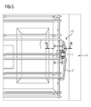
- FIG 2 illustrates the mounting element 1 as shown in Fig 1 schematically as a first side sectional view along the intersectional line (A-A) according to FIG 5
- FIG 3 illustrates the mounting element 1 as shown in Fig 1 schematically as a second side sectional view along the intersectional line (B-B) according to FIG 5
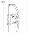
- FIG 4 illustrates schematically a perspective top view of the mounting element 1 shown in FIG1 , FIG 2 and FIG 3 .
- a mounting element 1 according to the first inventive embodiment is mounted on sidewall 4'' of a cavity 4' of an oven 3'.
- a support part 2 here a side grid 2' for an accessory part 12 such as a baking tray, is mounted on the cavity wall 4'' of the oven 3' using the inventive mounting element 1.
- the support portion 8 further comprises at least one holding means 11 for mounting the side grid 2', here formed as a retaining spring 11.
- retaining spring is of particular advantage in that the receiving and supporting of the side grid 2 and/or parts thereof is facilitated and improved, particularly where a side grid 2 and/or a part thereof, such as a rod or a bar is to be clamped.
- a flexibility of such retaining spring e.g. formed by a flexible sheet metal part, is of advantage.
- two holding means 11a and 11b are provided being substantially C-shaped support structures 15.
- Such mounting element 1 allows for an easy mounting of the mounting element 1 and the side grid 2'. More particularly, the insertion of a connecting portion 5 into an opening 6 of the cavity wall 4'' of the oven 3' allows for an easy mounting of the mounting element 1 and leads to a self-retaining fixation of the position of the mounting element 1 by the two tongue-shaped latch members 16.
- the two tongue-shaped latch members 16 connect the mounting element 1 to the cavity wall 4'' of the oven 3 after insertion of the connecting portion 5 of the mounting element 1 into the opening 6 of the cavity wall 4'' of the oven 3.
- the connecting portion 5 is located at a first side of the mounting element 1, which is to be introduced into the opening 6 of the cavity wall 4" of the oven 3, whereas the support portion 8 is located at a second side at the opposite side of the mounting element 1.
- Such mounting element 1 allows an easy mounting of the side grid 2' in that the support portion 8 of the mounting element 1 further comprises two holding means 11a and 11b for mounting the side grid 2', wherein said holding means 11a and 11b have a substantially C-shaped support structure.
- the substantially C-shaped support structure 15 supports the side grid 2'.
- the side grid 2' is suspended and supported by the C-shaped support structure 15.
- the open side of the "C" receives and supports the side grid 2', more specifically a part of a rod of said side grid 2'.
- the rod of said side grid is received by the C-shaped support structure 15, more specifically, by the open side of the "C", and thus the C-shaped support structure 15 supports the side grid 2' in a form-fit and force-fit clamping manner.
- the mounting element 1 also allows for an easy mounting of the side grid 2' of an oven 3' on a cavity wall 4'' of the oven 3', in that the side grid 2' or at least parts thereof are received and/or supported by the holding elements 11a and 11b, having substantially C-shaped support structure 15.
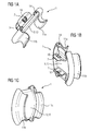
- the entire mounting element 1 is integrally formed and made out of one single sheet metal part by folding and punching the various elements and parts of the mounting element 1, which may be best seen from FIG 1b .
- Such configuration where the mounting element 1 is manufactured as a one piece and where each element and part thereof is formed as an integral part is of particular advantage as it is even more easy to mount said mounting element 1 and the number of pieces thus also costs is significantly reduced.
- the design of the fixation means 7 having tongue-shaped latch members 16 allows an easy mounting of the mounting element 1 on the cavity wall 4'' of the oven 3', particularly as the insertion of the connecting portion 5 into the opening 6 of the cavity wall 4'' of the oven 3', more precisely the sidewall of the cavity wall 4" of the oven 3' leads to a latching of the tongue-shaped latch members 16.
- the mounting element 1 is fixed in the opening 6 in its position in a self-retaining manner.
- the tongue-shaped latch members 16 are formed such that the tongue part thereof is movable relative to the connecting portion 5, particularly in a resilient manner.
- the tongue part of the tongue-shaped latch members 16 inclines in the direction of the opening 6 and the base portion 13.
- the tongue-shaped latch members 16 exhibit a force directed away from the opening 6 and the base portion 13 and thus lead to abutting the base portion 13 to the inner surface 10 of the cavity wall 4'' of the oven 3'. It will be immediately understood that in the mounted situation shown in FIGs 2 to 4 , 7 and 8 , the tongue-shaped latch members 16 are located on the opposite side of the opening 6 compared to the base portion 13.
- the use of such tongue-shaped latch members 16 is advantageous in that the abutting of the base portion 13 to the inner surface 10 of the cavity wall 4'' of the oven 3' leads to a more tight covering of the opening 6 and, thus to a less leaky passage for moisture and/or condensate.
- the support portion 8 and, particularly, the base portion 13 is formed to have a substantially round plate-shaped disc element 13 which covers the opening 6 in a tighter manner.
- the base portion 13 comprises an integrally formed circumferential sealing lip 14 for sealing the opening 6, which is formed by the rim of the base portion 13. It can be immediately seen that said sealing lip 14 is formed in that said rim is first bend towards the connecting portion 5 and, thus towards the first end of the mounting element 1. The lip thereby has a substantially U-shape in that the free end of the rim is bend back towards the second end of the mounting element 1.
- the bottom of the "U” forms the lip which is in contact with the surface 10 surrounding the opening 6 and thus seals the opening 6 against leak of moisture and/or condensate.
- the fixation means 7 are designed as tongue-shaped latch members 16, the sealing lip 14 is advantageously contacted to and pressed onto the surface 10 and thus seals the opening 6.
- the substantially C-shaped support structure 15 of the at least one holding means 11 for mounting the side grid 2 is formed by a bended leaf portion 15 projecting from the rim of the support portion 8.
- the bended leaf portion 15 projects from a part of the circumference of the rim of the support portion 8.
- the bend leaf portion 15 projects from the rim of the base portion 13 formed for abutting to the surface 10 of the cavity wall 4 of the oven 3.
- the bend leaf portions 15 are connected to the sealing lip. Accordingly, the rim of the sealing lip 14 at least at a part of the circumference of the substantially plate-shaped basis portion 13 is continued in, here two, bend leaf portions 15.
- the rim is bend to form the sealing lip 14, which has a substantially U-shaped form, in that a first end of the "U” is connected to or formed by the base portion 13, whereas the bend or basis of the "U” forms the sealing lip 14, and the second end of the "U” is connected to or continued to the bend leaf portion 15 of the substantially C-shaped support structure 15.
- a bended structure having an overall "S"-shaped cross-section is formed, wherein the upper bend of the "S” represents the substantially C-shaped support structure 15, and wherein the lower bend of the "S” represents the "U”-shaped sealing lip.
- the rim of the substantially plate-shaped basis portion 13 is bend first towards the connecting portion 5 and second back towards the frontal end comprising the support portion 8, thus forming a "U"-shaped sealing lip, and then, at third, in parts, here at two opposing positions, bend forming two substantially C-shaped support structures 15.
- the bended leaf portion 15 thereby projects away from and in the direction opposite to the connecting portion 5, i.e. away from a first side of the mounting element 1.
- the substantially C-shaped support structure 15 is located such that the basis and the lower end of the "C" is connected to the support portion 8, and, particularly, to the base portion 13.
- the second upper end of the "C” is, in the shown mounted situation projecting away from the cavity wall 4'' of the oven 3', i.e. away from the wall of the cavity to which the mounting element 1 is mounted and towards the inner part of the cavity, i.e. the heating compartment.
- the substantially C-shaped support structures 15 function as holding profiles and holding bracket, whereby the C-shaped support structures 15 with their inner radius are adapted to the shape, radius and circumference of the respective part of the side grid 2 to be received by the C-shaped support structure 15, here the bars of the side grid 2. Accordingly, the C-shaped support structure 15 is formed to support and receive the side grid 2, more precisely the bars thereof optimally.
- the two holding means 11a and 11b are arranged such that the receiving sides of said holding means 11a and 11b are facing away from each other.
- Such arrangement is configured such, that the opening of each "C" is facing away from the center and a central axis of the mounting element 1.
- the holding means 11a and 11b function as clamps which receive and support the bars of the grid 2'.
- two bars of the grid 2' are at least where they are connected to the mounting element 1 in parallel to each other and each substantially C-shaped support structure 15 receives and supports one bar of the grid 2'.
- each substantially C-shaped support structure 15 presses the received and supported bar of the grid 2' from the center of the mounting element 1 outwards.
- the side grid 2' is easily mounted to the mounting element 1 by plugging the side grid 2' onto the mounting element 1 in that the mounting element 1 is located and clamped in between the two bars of such side grid 2' as may be best seen in FIG 4 .
- the embodiment of the invention described with reference to the drawings has the advantage, that an easy mounting of the side grid 2' of the oven 3' on a cavity wall 4'' of the oven 3' is provided. More particularly, the leak of moisture and/or condensate through the opening 6 is reduced. Moreover, the described embodiment provides a cost and effort optimized solution for mounting a side grid 2' of the oven 3' on a cavity wall 4" of the oven 3'. Moreover, in the prior art an open hole was left in the sidewall of the cavity of an oven through which moisture and/or condensate may leak, whereas the mounting element 1 according to the described embodiment closes the fixation opening by itself. One side of the sheet metal is bent into a hook, which latches into the cavity, the other side is bent into carrying structure, supporting the side grid.
Landscapes
- Engineering & Computer Science (AREA)
- Chemical & Material Sciences (AREA)
- Combustion & Propulsion (AREA)
- Mechanical Engineering (AREA)
- General Engineering & Computer Science (AREA)
- Cookers (AREA)
Abstract
said mounting element comprising fixation means for fixating said mounting element inside an opening of said component ,
said mounting element further comprising holding means for holding said support part ,
characterized in that
said mounting element comprises a continuous base portion , wherein said fixation means and said holding means are arranged at respective opposing sides of said base portion.


Description
- The present invention relates to a household appliance with a component and with a support part attached to said component by means of at least one mounting element made from sheet metal and such mounting element.
- In a household appliance and particularly in a kitchen appliance, such as an oven, mounting elements are arranged for mounting supporting parts, such as side grids, for supporting accessory parts, such as baking trays. In the known solutions, such mounting elements are either, difficult to handle, e.g. have to be screwed, often consist of many parts, or have further disadvantages. For example, a sheet metal part is known as mounting element for a side grid of an oven, where the side grid, more particularly rod or bar ends thereof, is to be put through a hole in the sheet metal part and a hole of the wall of the oven muffle. Thereby, the hole in the muffle wall is not tight and condensate and/or moisture leaks through the hole in the muffle wall and thus into the inner parts of the oven, where e.g. wires are fixed, which may lead to damage of the oven. Other solutions, e.g. comprising screws or bolts, are disadvantageous due to high costs and not easy to handle.
- The documents
EP 2 522 914 A1 andDE 10 2011 081 587 A1 describe fixation elements for a grid comprising a rear connecting portion for insertion into a recess in a household appliance component, wherein at the connecting portion a tongue-shaped latch member is formed. - However, also according to the description of said document the grid, particularly the end of a rod or bar thereof, is to be put through a hole in the sheet metal part and a hole of the wall of the oven muffle. Thus condensate and/or moisture may leak through the hole in the muffle wall and thus into the inner parts of the oven.
- It is an object of the present invention to provide a mounting element, which allows an easy and cost effective mounting of a support part of a household appliance, such as a side grid of an oven.
- It is a further object of the present invention to provide a mounting element where no condensate and/or moisture may leak out, particularly through a hole of a component the household appliance, such as a cavity or muffle.
- The above objects of the invention are achieved by a household appliance according to
claim 1 and a mounting element according to claim 15. - A household appliance according to
claim 1 comprises a component and a support part attached to said component by means of at least one mounting element made from sheet metal, wherein said mounting element comprises a connecting portion comprising at least one fixation means for fixating said mounting element inside an opening of said component , wherein said mounting element further comprises a support portion comprising at least one holding means for holding said support part , and wherein said mounting element comprises a continuous base portion , wherein said connecting portion comprising the at least one fixation means and said support portion comprising the at least one holding means are arranged at respective opposing sides of said base portion. - A mounting element as used herein is for mounting a support part, e.g. a side grid of a household appliance on a component of the household appliance or a part thereof, e.g. an inner compartment od said household appliance , for example a muffle or a cavity of an oven, or a part thereof.
- It will be understood that the connection portion and the support portion are arranged at respective opposing sides of said base portion of the mounting element.
- Such connecting portion, preferably is for insertion of said connecting portion into an opening of the component of the household appliance or a part thereof
- An opening as used herein, preferably refers to an opening in said component or in at least a part thereof. For example, an opening is a hole, for example a hole in said component, e.g. a hole in an oven cavity, or a hole in an oven cavity wall.
- A household appliance according to the present invention, comprises at least one such opening in the component of the household appliance or a part thereof, preferably in a sidewall of such inner compartment thereof, for insertion of a connecting portion of a mounting element according to the present invention.
- It is an embodiment of the present invention that the opening is an opening in a wall of an oven cavity, preferably the wall is a sidewall of said oven cavity.
- For example, a wall is a sidewall of a muffle or cavity of an oven, to which a support part, such as a support grid for a baking tray is to be mounted by the mounting element.
- In alternative, a wall is any wall of an oven cavity, preferably a top wall of an oven cavity to which a support part, such as a heating element for heating the oven cavity is to be mounted by the mounting element.
- Said connecting portion comprises at least one fixation means for fixing said mounting element to the component of the household appliance or a part thereof.
- The mounting element further comprises a support portion, wherein said support portion comprises the at least one holding means for holding said support part.
- The present inventors surprisingly found that such mounting element according to the present invention allows for an easy mounting of the mounting element and, moreover of the support part to said mounting element. More particularly, the insertion of a connecting portion into an opening of the component of the household appliance or a part thereof allows for an easy mounting of the mounting element and, preferably leads to a fixation, preferably a self-retaining fixation, of the position of the mounting element by the at least one fixation means. Thus, the at least one fixation means connects the mounting element to the component of the household appliance or a part thereof after insertion of the connecting portion of the mounting element into an opening of the component of the household appliance or a part thereof.
- It will be understood that preferably the connecting portion is located at a first side of the base portion of the mounting element which is to be introduced into the opening of the component of the household appliance or a part thereof, whereas the support portion, more preferably is located at a second side of the base portion, more specifically, the opposite side of the base portion of the mounting element. Thereby it is to be understood that the mounting element is inserted into the opening of the component of the household appliance or a part thereof from one side or the component, preferably the side where the support part is to be mounted. This side preferably, is the side facing an inner compartment of the household appliance, e.g. an oven cavity, and is referred to herein, preferably as the front side or front surface of the component. Accordingly, the opposing side of the component, e.g. the opposing side of an oven cavity wall, is the side facing away from the oven cavity and facing, for example, the inner structure of the household appliance. This opposing side is referred to herein, preferably as the rear side or rear surface.
- Accordingly, in a mounted situation, where the connecting portion is inserted into the opening from the front side, the connecting portion is inserted through the opening, whereas the connecting portion is located at the side of the opening where the support part is to be mounted to the mounting element, i.e. the side of the front side.
- Preferably, the support portion of the mounting element according to the present invention comprises at least one, preferably at least two, more preferably two, holding means.
- It will be understood that one holding means of one first mounting element may be sufficient for mounting a support part of a household appliance on a component of the household appliance or a part thereof, particularly, if said one holding means of said one first mounting element is applied in combination with one further holding means of one second mounting element, however, two or more than two holding means being part of one mounting element are advantageous in that the usability of such mounting element comprising at least two, preferably two, holding means is considered to be, in general, higher.
Preferably, the inventive mounting element is made out of one sheet metal part, preferably a folded sheet metal. - In an advantageous embodiment of the inventive household appliance according to the present invention, said mounting element is one integral piece of sheet metal.
- Such configuration where the mounting element is manufactured as one piece, and/or where each element is formed as integral piece of sheet metal is of particular advantage as it is even easier to mount said mounting element and the number of pieces thus also costs is significantly reduced.
- It will be immediately understood that such configuration is of particular advantage. Preferably, each element and part of the mounting element is formed as an integral part thereof. Preferably, the mounting element is manufactured from one single sheet metal part by folding and/or punching the elements, portions and parts of the mounting element. Thereby, the mounting element is manufactured, preferably, in one piece.
- However, it will also be understood that, although metal is preferred as material of the inventive mounting element, the mounting element according to the present invention may be manufactured from other materials within the scope of the present invention.
- It is also an embodiment of the present invention that the mounting element in one piece from a synthetic material, such as plastic, preferably a heat and/or corrosion resistant material.
- In a further advantageous embodiment of the inventive household appliance according to the present invention, said base portion of said mounting element is arranged to cover said opening of said component when the mounting element is fixated inside said opening of the component by means of said at least one fixation means, preferably, wherein said household appliance is an oven, said component is a heated oven cavity and said opening that is covered by said base portion of the mounting element is a hole in a wall of said oven cavity.
- A continuous base portion as used herein, preferably refers to a portion of said mounting element, being essentially plate-shaped. Such base portion preferably has a continuous surface, more preferably without a hole or recess or the like.
- Preferably, the support portion or at least a part thereof is or is also formed to be a substantially plate-shaped.
- Such plate-shape of the support portion and/or the base portion is of advantage in that, the opening is covered, preferably, in a substantially tighter manner reducing, more preferably, the leakage of moisture or steam out of the opening. In particular in a heated oven cavity, an important reduction in the energy consumption can be achieved by the mounting element of the present invention which effectively closes the hole in a wall of the oven cavity in that it comprises a continuous base portion, wherein the fixation means of its connecting portion and the holding means of its support portion are arranged at respective opposing sides of its continuous base portion, which allows to arrange said base portion to cover, in particular to essentially seal, said hole in the wall of the oven cavity inside which said fixation means of the connecting portion of the mounting element can be fixed.
- In a preferred embodiment of the mounting element according to the present invention said base portion, more preferably being substantially plate-shaped base portion is a substantially round disc element.
- It will be understood that it is particularly preferred that the support portion and/or a part thereof and/or the base portion and/or a part thereof is formed such that it is for covering the opening.
- This is advantageous, particularly, where a fixation means is designed as a latch member, in that the opening is covered and less moisture and/or condensate may escape through the opening.
- In a mounted situation of the mounting element according to the present invention, where the connecting portion is inserted into the opening from the front side, the base portion, preferably by fixation due to the at least one fixation means, is abutting to a surface of the component of the household appliance or a part thereof, thereby the base portion or a part thereof, preferably, covers the opening. This is of particular advantage as the leaking of moisture and/or condensate out of the opening is less, preferably totally avoided. It will also be immediately understood that the side is a side or surface of the component of the household appliance or a part thereof on the side of the opening where the connecting portion is located and where the support part is to be mounted to the mounting element, preferably the front side.
- It will be immediately understood that the base portion is configured for abutting to a surface of the component of the household appliance or a part thereof, preferably at the front side, the opening is covered by a part of the mounting element, preferably the base portion, and thus less condensation leaks out of said opening.
- The mounting element according to the present invention is of particular advantage as it is easily mounted to the component of the household appliance or a part thereof by inserting the support part into the opening of the component of the household appliance or a part thereof. By said easy insertion and mountability, also fewer costs arise.
- In other words, where earlier solutions left an open hole or passage in the component of the household appliance or a part thereof, the inventive mounting element closes the opening, which is used for fixation of the mounting element by itself, more particularly by the base portion and/or the support portion, or at least parts thereof.
- In a further advantageous embodiment of the inventive household appliance according to the present invention, said mounting element comprises at least one sealing portion arranged adjacent to said base portion of said mounting element , wherein said sealing portion is in contact with a surface surrounding said opening.
- Such sealing portion is arranged adjacent to said base portion, however, it will be understood that such sealing portion, preferably is formed integrally by the base portion and/or may be formed as a separate part. In an embodiment, such sealing portion is manufactured from sheet metal.
- A sealing portion is in contact with a surface surrounding said opening.
- Preferably, the at least one sealing portion, is formed to be a sealing lip, preferably an at least partially circumferential sealing lip.
- It will be understood that such sealing lip may be formed integrally by the base portion or may be formed as a separate part.
- In a preferred embodiment such sealing portion and, more particularly, a rim of the base forms such sealing lip, portion, preferably by the rim of a substantially plate-shaped base portion. More preferably, where the connecting portion is located at a first side of the base portion of the mounting element which is to be introduced into the opening of the component of the household appliance or a part thereof, and where the support portion, more preferably is located at a second side, preferably the opposite side, of the base portion of the mounting element, there the at least one sealing portion and/or sealing lip is formed by the rim of the base portion or a part thereof, in that, preferably, said rim is first bend towards the connecting portion and/or towards the first side of the mounting element.
- The lip may have a substantially U-shape in that the free end of the rim of the base portion may be bend back towards the second side of the mounting element. Thus, it will be understood that the bottom of the "U" will form the lip, which is to be in contact with the side of the component of the household appliance or a part thereof, surrounding at least partially the opening and thus, preferably sealing at least partially the opening.
- In a further advantageous embodiment of the inventive household appliance according to the present invention, said fixation means comprises at least one locking means.
- This preferably is for locking the mounting element and, particularly the fixation means in the opening and, more particularly, for avoiding an unwanted removal of said mounting element from said opening. Therefore, the fixation means are preferably configured such that the mounting element is secured against such unwanted removal out of the opening, particularly secured against an unwanted removal by a pulling of the mounting element out of the opening.
- In a further advantageous embodiment of the inventive household appliance according to the present invention, said sealing portion is arranged as a spring-loaded sealing portion , preferably cooperating with said locking means.
- This is of particular advantage for the sealing capacity of such sealing portion, as the spring force further leads to an improved contact of the sealing portion and a side of the compartment.
- In a further advantageous embodiment of the inventive household appliance according to the present invention, said locking means comprise at least one detent in communication with a rear side of said component.
- Preferably, said detent is designed as latch member or a tongue-shaped latch member.
- Such detent is of particular advantage in further securing the mounting element against unwanted removal out of the opening, particularly securing against an unwanted removal by a pulling of the mounting element out of the opening. Such pulling out of the mounting element out of the opening is only possible, if at first the detent is pressed and/or released.
- It is to be understood that, as the base portion is abutting to a side of the component of the household appliance or a part thereof, and particularly, where the fixation means comprises at least one such locking means, preferably for latching of the fixation means, preferably designed as detent, more preferably a latch member or a tongue-shaped latch member, a sealing portion and/or sealing lip is advantageously contacted to and/or pressed onto the side and thus sealing the opening.
- This allows an easy mounting of the mounting element on the component of the household appliance or a part thereof, particularly as the insertion of the connecting portion into an opening of the component of the household appliance or a part thereof, e.g. the sidewall of a cavity or muffle of an oven, leads to a latching of the fixation means.
- In accordance therewith, the mounting element is fixed in the opening in its position in a self-retaining manner.
- It will be understood that such fixation means, preferably being tongue-shaped, is formed such that it or a part thereof is movable relative to the connecting portion, particularly in a resilient manner. The fixation means may incline in the direction of the opening and the base portion. Thus, the fixation means may exhibit a force directed away from the opening and the base portion and may thus lead to abutting the base portion to a side of the component of the household appliance or a part thereof. It will be immediately understood that in a mounted situation the fixation means is located on the opposite side of the opening compared to the base portion, i.e. the rear side of the opening. Such fixation means, particularly being tongue-shaped, is also manufactured easily, for example, by punching out the tongue element.
- It is to be understood that such latch member is advantageous in that the abutting of a base portion to a side of the component of the household appliance or a part thereof may lead to a more tight covering of the opening and, thus to a less leaky passage for moisture and/or condensate.
- In a further advantageous embodiment of the inventive household appliance according to the present invention, said opening in said component has an asymmetric shape, wherein said fixation means are adapted to communicate with said asymmetry of said opening.
- Such asymmetric shape advantageously secures the mounting element from unwanted turning or rattling.
Such asymmetrically shaped opening may thus have various shapes, for example, a rectangular shape. - In a further advantageous embodiment of the inventive household appliance according to the present invention, said holding means are arranged for detachable clamping of said support part.
- It will be immediately understood that the support part is for supporting an accessory part, wherein preferably, the accessory part is a support for a food product, more preferably, selected from the group comprising a support tray, such as a baking tray, and a grid.
- In an alternative embodiment, the support part is a heating element for heating the oven cavity, wherein the heating element can be fixed to a wall of the oven cavity by the mounting element of the invention.
- In a preferred embodiment, the support part is selected from the group comprising a side grid and a rail system for an oven cavity.
- It will be immediately understood that the mounting element according to the present invention is also advantageous in allowing an easy mounting of the support part in that the support portion of the mounting element further comprises at least one holding means for mounting the support part, characterized in that said holding means are arranged for detachable clamping of said support part.
- In a preferred embodiment an at least one fixation means is a holding profile, more preferably a holding bracket.
- Preferably, such support part or a part thereof, e.g. the rails or bars of a side grid, are clamped onto the holding means of the mounting element(s) which are arranged for detachable clamping of said support part or a part thereof, preferably wherein said support part is a side grid for an oven cavity.
- Preferably, a first holding means and an at least one further holding means are arranged on the support portion such that the holding means are facing away from each other.
- Such arrangement is configured such, that, preferably, the sides where the holding element will be in contact with the support part, is facing away from a center and/or a central axis of said mounting element, more preferably of said base portion. It will be immediately understood that such configuration is of particular advantage for mounting a support part, such as a grid or rail.
- Where, for example, a grid or rail is to be mounted the first holding means and the at least one further holding means may function as clamps which receive and support parts of a grid or rail, particularly, where rods or bars of such grid or rail are, at least partially configured in parallel to each other each substantially C-shaped support structure receives and supports one rod or bar of such grid or rail. More particularly, such arrangement is configured such, that, preferably, each substantially C-shaped support structure presses the received and supported rod or bar of such grid or rail from the center of the mounting element outwards. Where the received and supported rods or bars of such support part are connected the support part is easily mounted to the mounting element by plugging the support part onto the mounting element in that the mounting element is located and clamped in between the two rods or bars of such support part.
- In a further advantageous embodiment of the inventive household appliance according to the present invention, said holding means are arranged for form-fit and/or force-fit clamping of said support part.
- This is of particular advantage in that form-fit and/or force-fit clamping is advantageous in fixing the support part or parts thereof in the fixation means.
- By way of an example, the holding means may have a substantially C-shaped form, wherein the C-shaped form is fitting to a bar or rod of a guide rail. Such substantially C-shaped form of the at least one holding means is of particular advantage if the holding means are arranged such, that the holding means may clamp said support part. For example, the C-shape of such holding means may be formed as at least partially circumferential C-shaped notch in the rim of the base portion, particularly, where the base portion is formed as a disc.
- Said form-fit and/or force-fit clamping of said support part supports the fixation of the support part by the fixation means.
- The support part may be suspended and/or supported by the form-fit and/or force-fit clamping. Preferably, a receiving side of a holding means , e.g. an open side of a "C" of a substantially C-shaped holding means , may receive and/or support the support part and/or parts thereof. In way of example, the support part may be a side grid for supporting a baking tray in an oven. It will be understood that in such case a rod or a bar of said side grid, or a part thereof may be received by such receiving side of the holding means, e.g. a C-shaped support structure, more preferably, by the open side of the "C", and thus the holding means supports the support part in a form fit clamping manner.
- In a further advantageous embodiment of the inventive household appliance according to the present invention, said holding means comprise at least two spring-loaded latches.
- In a preferred embodiment of the inventive mounting element, the holding means alternatively or additionally are designed as spring elements, and, more preferably, are arranged to exhibit a spring force directed against the support part or a part thereof and thus mediate advantageous spring-force mediated clamping of said support part or part thereof.
- Thus, the mounting element also allows for an easy mounting of the support part of a household appliance on a component of the household appliance or a part thereof, in that the support part or at least parts thereof are received and/or supported by the holding means , preferably additionally in a form-fit and/or force-fit clamping of said support part.
- Preferably, the holding means is formed as a retaining spring-loaded latch.
- Such spring-loaded latches, preferably retaining spring-loaded latches, is of particular advantage in that the receiving and supporting of the support part and/or parts thereof is facilitated and improved, particularly where a support part and/or a part thereof, such as a rod or a bar is to be clamped. Here, a flexibility of such retaining spring, e.g. formed by a flexible sheet metal part, is of advantage.
- Preferably, the holding means formed as a spring-loaded latch is formed by a bended leaf portion projecting from the rim of the support portion.
- Such bended leaf portion projects at least from a part of the circumference of the rim of the support portion, particularly where the support portion and/or the base portion or at least a part thereof is formed to be a substantially plate-shaped base portion. More particularly, the bended leaf portion may project at least from a part of the circumference of the rim of the flange element and/or may project of at least a part thereof or may project at least from a part of the circumference of the rim of the substantially plate-shaped base portion.
Such bend leaf portion may project from the rim of a base portion formed for abutting to a side or surface of the component of the household appliance or a part thereof. Where such base portion comprises at least one sealing portion for sealing the opening and/or a sealing lip, said bend leaf portion may be connected thereto. - Accordingly, a rim of a base portion and/or of an at least one sealing portion for sealing the opening and/or of a sealing lip or a portion thereof, may be continued in a said bend leaf portion.
- For example, such rim may be bend to form a sealing lip having, for example, a substantially U-shaped form, in that a first end of the "U" is connected to or formed by the base portion, whereas the bend or base of the "U" forms the sealing lip, and the second end of the "U" is connected to or continued to the bend leaf portion of a holding means, for example, a substantially C-shaped support structure.
- As a result, a bended structure having an overall "S"-shaped cross-section may be formed, wherein the upper bend of the "S" represents the holding means, e.g. a substantially C-shaped support structure, and wherein the lower bend of the "S" represents the "U"-shaped sealing lip.
- In other words the rim of a the support portion and/or the base portion and/or a substantially plate-shaped base portion or at least a part may be bend first towards the connecting portion and second back towards the front side comprising the support portion, thus forming a "U"-shaped sealing lip, and then, at third, bend forming a substantially C-shaped support structure.
- Said bended leaf portion, preferably projects away from and/or in the direction opposite to the connecting portion, preferably away from a first end of the mounting element. Accordingly, a substantially C-shaped support structure is located such that the base and the lower end of the "C" is, preferably connected to the support portion, and more preferably to the base portion.
- The second upper end of the "C" is, in a mounted situation, projecting away from the component of the household appliance or a part thereof, i.e., for example, away from the wall of the muffle to which the mounting element is mounted.
- Preferably, the holding means, e.g. the C-shaped support structure, preferably the inner radius of the C-shaped support structure, is adapted to the shape of the respective part of the support part to be received by the holding means, e.g. the C-shaped support structure.
- Such adaptation may, for example, be such that the inner radius of the C-shaped support structure is adapted to the shape, radius and/or circumference of a part of the support part, such as a rod or bar or a part thereof of a side grid or rail to be mounted. Accordingly, the C-shaped support structure is formed to support and/or receive the support part optimally.
- In a further advantageous embodiment of the inventive household appliance according to the present invention, said support part is attached to said component by at least two mounting elements. It will be immediately understood that for mounting a support part of a household appliance on a component of the household appliance or a part thereof one or more than one mounting elements according to present invention may be used, and accordingly may be inserted each in one separate opening of the component of the household appliance or a part thereof. A household appliance according to the present invention may comprise thus, at least one mounting element according to the present invention, preferably, a household appliance according to the present invention comprises more than one mounting elements according to the present invention. Where more than one mounting elements according to the present invention are applied in a household appliance according to the present invention said mounting elements may be same or different and be adapted to the particular needs.
- In a further advantageous embodiment of the inventive household appliance according to the present invention, said component is an inner compartment or a part thereof, e.g. a cavity or a sidewall of a cavity of said household appliance , wherein, preferably, said sidewall is part of a muffle.
- A component as used herein, preferably is a part of a household appliance , such as a cavity or a muffle, or a sidewall of a cavity or of a muffle.
- Such household appliance comprises a component of the household appliance or a part thereof to which a support part is to be mounted. Such component of the household appliance or a part thereof, preferably is an inner compartment of the household appliance , more preferably a muffle, most preferably a muffle of an oven.
- Preferably, of the inventive mounting element the component of the household appliance or a part thereof is an inner compartment of the household appliance , preferably a muffle, more preferably a muffle of an oven.
- In connection therewith it is to be understood that where the component of the household appliance or a part thereof is an inner compartment of the household appliance , particularly with regard to the muffle of an oven where usually high temperatures are reached and, particularly, cooking liquids will vaporize to moisture, or the interior of a fridge, where due to cooling moisture and/or condensate is formed, the covering of the opening is of particular advantage in that the leaking of moisture and/or condensate is reduced.
- In a further advantageous embodiment of the inventive household appliance according to the present invention, said support part is a side grid, preferably arranged inside said component.
- Such support part is formed to be mountable on a component of the household appliance or a part thereof using a mounting element, wherein the mounting element is a mounting element according to the present invention.
- It will be understood that such support part is configured such that the mounting on a mounting element according to the present invention is possible. Accordingly, such support part may be adjusted to the dimension and shape of the mounting element according to the present invention. For example, where the support part is a support rail for a baking tray or the like, the distance between two rods or bars, or at least at a part thereof is chosen according to the dimensions of the support portion and/or, for example, the distance between two holding means.
- The above described problems are also advantageously solved by am mounting element according to claim 15. Such mounting element is for mounting a support part of a household appliance according to the present invention.
- Preferably, a household appliance according to the present invention is a kitchen appliance, more preferably for preparing and/or storing food. Preferably, a household appliance according to the present invention is selected from the group comprising an oven.
- All described embodiments of the invention have the advantage, that an easy mounting of a support part of a household appliance , e.g. a side grid, on a component of the household appliance or a part thereof, e.g. a cavity or cavity sidewall, is provided. More particularly, the leak of moisture and/or condensate through an opening in said component, e.g. a hole in a cavity sidewall, is reduced. Moreover, the present invention provides a cost and effort optimized solution for mounting such support part of a household appliance on a component of the household appliance or a part thereof.
- The present invention will be described in further detail with reference to the drawings, in which
-
FIGs 1A, 1B and 1C illustrate a series of perspective schematically views of a mounting element according to the present invention showing the first inventive embodiment; -
FIG 2 illustrates schematically a first side sectional view of a mounting element according to the present invention showing the first inventive embodiment; -
FIG 3 illustrates schematically a second side sectional view of a mounting element according to the present invention showing the first inventive embodiment; -
FIG 4 illustrates schematically a perspective top view of a part of a side grid mounted on a mounting element according to the present invention showing the first inventive embodiment. -
FIG 5 illustrates a perspective schematically view of a side grid mounted on a mounting element according to the present invention showing the first inventive embodiment; -
FIG 6A and 6B illustrates a perspective schematically view of a part of a component having an opening for inserting the mounting element according to the first inventive embodiment; -
FIG 7 illustrates a perspective schematically view of a side grid mounted on two mounting elements according to the present invention showing the first inventive embodiment; and -
FIG 8 illustrates a perspective schematically view of a side grid mounted on two mounting elements according to the present invention showing the first inventive embodiment. -
FIGs 1A, 1B and 1C shown a first inventive embodiment of a mountingelement 1 according to the present invention. - Such mounting element is for mounting and/or attaching a
support part 2, here a side grid to acomponent 4, here a cavity wall, of a household appliance 3, here an oven, by means of at least one mountingelements 1 made from sheet metal. As may be best seen fromFIGs 7 or8 , here to mountingelements 1 are used to attach the side grid 2' to onewall 4" of the oven cavity 4'. However, at the opposing wall of the cavity 4', a second side grid 2' may be attached as well. Thus, such oven 3 according to the first inventive embodiment may comprise four mountingelements 1 according to the present invention. - Said mounting
elements 1 comprise a connectingportion 5, which comprises at least one fixation means 7 for fixating said mountingelement 1 inside anopening 6 of said cavity wall 4''. Saidopening 6 may be best seen inFIGs 6A and 6B . - The mounting
element 1 further comprises asupport portion 8 comprising at least one holding means 11 for holding saidside grid 2, wherein said mountingelement 1 comprises acontinuous base portion 13, wherein said connectingportion 5 comprises the at least one fixation means 7 and saidsupport portion 8 comprising the at least one holding means 11 are arranged at respective opposing sides of saidbase portion 13, which may be best seen fromFIGs 1A andFIG 2 . - As may be best seen from
FIG 1B the inventive mountingelement 1 is one integral piece of sheet metal. - In a mounted stage, as may be best seen in
FIG 4 ,FIG 5 ,FIG 7 andFIG 8 , thebase portion 13 of said mountingelement 1 is arranged to cover saidopening 6 of saidcavity wall 4". - The mounting
element 1 further comprises at least one sealingportion 14 arranged adjacent to saidbase portion 13 of said mountingelement 1, which may be best seen fromFIG2 . Said sealingportion 14 is in contact with a side surrounding saidopening 6. The sealingportion 14 is arranged as a spring-loadedsealing portion 14, which cooperates with said locking means 16. - Each fixation means 7, here comprises such locking means 16, which comprises a detent in communication with a rear side of said cavity wall 4'', which may also be best seen from
FIG 2 . - The
opening 6 in said cavity wall 4'' has an asymmetric shape, which may be taken fromFIG 6A and FIG 6B . Said fixation means 7 are adapted to communicate with said asymmetry of saidopening 6. As may be seen fromFIG 7 andFIG 8 , the mounting element may be inserted into an opening in different orientations. It will be immediately understood, that the orientation is also dependent on the orientation of suchasymmetric opening 6. - In the inventive first embodiment shown in the present Figures, the holding means 11 are arranged for detachable clamping of said side grid 2', and, particularly, for form-fit and force-fit clamping of said side grid 2'. This may, in particular, be taken from
FIG 2 andFIG4 . Here, the holding means 11 comprise two spring-loaded latches 15. - As may be best seen from
FIG 7 andFIG 8 , in the embodiment shown here, each side grid 2' is attached to said cavity wall 4'' by two mountingelements 1. It will be understood, however, that at least one, but also more than two mountingelements 1 can be applied in accordance with the present invention. - Here, the
side grid 2 is arranged inside the cavity, and an accessory part 12, e.g. a baking tray, can be guided in on said side grid 2'. - More particularly,
FIG 2 illustrates the mountingelement 1 as shown inFig 1 schematically as a first side sectional view along the intersectional line (A-A) according toFIG 5 , andFIG 3 illustrates the mountingelement 1 as shown inFig 1 schematically as a second side sectional view along the intersectional line (B-B) according toFIG 5 .FIG 4 illustrates schematically a perspective top view of the mountingelement 1 shown inFIG1 ,FIG 2 andFIG 3 . - As may be best seen from
FIG 5 ,FIG 7 andFIG 8 a mountingelement 1 according to the first inventive embodiment is mounted on sidewall 4'' of a cavity 4' of an oven 3'. Asupport part 2, here a side grid 2' for an accessory part 12 such as a baking tray, is mounted on the cavity wall 4'' of the oven 3' using the inventive mountingelement 1. - The
support portion 8 further comprises at least one holding means 11 for mounting the side grid 2', here formed as a retainingspring 11. Such retaining spring is of particular advantage in that the receiving and supporting of theside grid 2 and/or parts thereof is facilitated and improved, particularly where aside grid 2 and/or a part thereof, such as a rod or a bar is to be clamped. Here, a flexibility of such retaining spring, e.g. formed by a flexible sheet metal part, is of advantage. Here two holding means 11a and 11b are provided being substantially C-shaped support structures 15. - Such mounting
element 1 allows for an easy mounting of the mountingelement 1 and the side grid 2'. More particularly, the insertion of a connectingportion 5 into anopening 6 of the cavity wall 4'' of the oven 3' allows for an easy mounting of the mountingelement 1 and leads to a self-retaining fixation of the position of the mountingelement 1 by the two tongue-shapedlatch members 16. Thus, the two tongue-shapedlatch members 16 connect the mountingelement 1 to the cavity wall 4'' of the oven 3 after insertion of the connectingportion 5 of the mountingelement 1 into theopening 6 of the cavity wall 4'' of the oven 3. - It can be immediately seen that the connecting
portion 5 is located at a first side of the mountingelement 1, which is to be introduced into theopening 6 of thecavity wall 4" of the oven 3, whereas thesupport portion 8 is located at a second side at the opposite side of the mountingelement 1. Thereby it is immediately clear that the mountingelement 1 was inserted into theopening 6 of the cavity wall 4'' of the oven 3' from the side where theside grid 2 is mounted, i.e. from the side of the inner room of the oven cavity'. Accordingly, in the mounted situation as shown in theFIGs 2 to 5 ,7 and8 , where the connectingportion 5 is inserted into theopening 6, the connectingportion 5 is inserted through theopening 6, whereas the connectingportion 5 is located at the side of theopening 6 where the side grid 2' is mounted to the mountingelement 1. Thereby thebase portion 13, by fixation due to the at least one fixation means 7, is abutting to theinner surface 10 of the cavity wall 4'' of the oven 3, thereby thebase portion 13 covers theopening 6 entirely. This is of particular advantage as the leaking of moisture and/or condensate out of theopening 6 is avoided. - Such mounting
element 1 allows an easy mounting of the side grid 2' in that thesupport portion 8 of the mountingelement 1 further comprises two holding means 11a and 11b for mounting the side grid 2', wherein said holding means 11a and 11b have a substantially C-shaped support structure. The substantially C-shaped support structure 15 supports the side grid 2'. The side grid 2' is suspended and supported by the C-shaped support structure 15. As may be best seen inFIG 2 the open side of the "C" receives and supports the side grid 2', more specifically a part of a rod of said side grid 2'. The rod of said side grid is received by the C-shaped support structure 15, more specifically, by the open side of the "C", and thus the C-shaped support structure 15 supports the side grid 2' in a form-fit and force-fit clamping manner. Thus, the mountingelement 1 also allows for an easy mounting of the side grid 2' of an oven 3' on a cavity wall 4'' of the oven 3', in that the side grid 2' or at least parts thereof are received and/or supported by the holdingelements - Here the entire mounting
element 1 is integrally formed and made out of one single sheet metal part by folding and punching the various elements and parts of the mountingelement 1, which may be best seen fromFIG 1b . - Such configuration where the mounting
element 1 is manufactured as a one piece and where each element and part thereof is formed as an integral part is of particular advantage as it is even more easy to mount said mountingelement 1 and the number of pieces thus also costs is significantly reduced. - The design of the fixation means 7 having tongue-shaped
latch members 16 allows an easy mounting of the mountingelement 1 on the cavity wall 4'' of the oven 3', particularly as the insertion of the connectingportion 5 into theopening 6 of the cavity wall 4'' of the oven 3', more precisely the sidewall of thecavity wall 4" of the oven 3' leads to a latching of the tongue-shapedlatch members 16. In accordance therewith, the mountingelement 1 is fixed in theopening 6 in its position in a self-retaining manner. It will be understood that the tongue-shapedlatch members 16 are formed such that the tongue part thereof is movable relative to the connectingportion 5, particularly in a resilient manner. The tongue part of the tongue-shapedlatch members 16 inclines in the direction of theopening 6 and thebase portion 13. Thus, the tongue-shapedlatch members 16 exhibit a force directed away from theopening 6 and thebase portion 13 and thus lead to abutting thebase portion 13 to theinner surface 10 of the cavity wall 4'' of the oven 3'. It will be immediately understood that in the mounted situation shown inFIGs 2 to 4 ,7 and8 , the tongue-shapedlatch members 16 are located on the opposite side of theopening 6 compared to thebase portion 13. The use of such tongue-shapedlatch members 16 is advantageous in that the abutting of thebase portion 13 to theinner surface 10 of the cavity wall 4'' of the oven 3' leads to a more tight covering of theopening 6 and, thus to a less leaky passage for moisture and/or condensate. - Here the
support portion 8 and, particularly, thebase portion 13 is formed to have a substantially round plate-shapeddisc element 13 which covers theopening 6 in a tighter manner. Moreover, thebase portion 13 comprises an integrally formedcircumferential sealing lip 14 for sealing theopening 6, which is formed by the rim of thebase portion 13. It can be immediately seen that said sealinglip 14 is formed in that said rim is first bend towards the connectingportion 5 and, thus towards the first end of the mountingelement 1. The lip thereby has a substantially U-shape in that the free end of the rim is bend back towards the second end of the mountingelement 1. Thus, it will be understood that the bottom of the "U" forms the lip which is in contact with thesurface 10 surrounding theopening 6 and thus seals theopening 6 against leak of moisture and/or condensate. As the fixation means 7 are designed as tongue-shapedlatch members 16, the sealinglip 14 is advantageously contacted to and pressed onto thesurface 10 and thus seals theopening 6. - It can also be immediately seen that the substantially C-shaped support structure 15 of the at least one holding means 11 for mounting the
side grid 2 is formed by a bended leaf portion 15 projecting from the rim of thesupport portion 8. The bended leaf portion 15 projects from a part of the circumference of the rim of thesupport portion 8. The bend leaf portion 15 projects from the rim of thebase portion 13 formed for abutting to thesurface 10 of thecavity wall 4 of the oven 3. It can also be immediately seen that the bend leaf portions 15 are connected to the sealing lip. Accordingly, the rim of the sealinglip 14 at least at a part of the circumference of the substantially plate-shapedbasis portion 13 is continued in, here two, bend leaf portions 15. The rim is bend to form the sealinglip 14, which has a substantially U-shaped form, in that a first end of the "U" is connected to or formed by thebase portion 13, whereas the bend or basis of the "U" forms the sealinglip 14, and the second end of the "U" is connected to or continued to the bend leaf portion 15 of the substantially C-shaped support structure 15. As a result a bended structure having an overall "S"-shaped cross-section is formed, wherein the upper bend of the "S" represents the substantially C-shaped support structure 15, and wherein the lower bend of the "S" represents the "U"-shaped sealing lip. In other words, the rim of the substantially plate-shapedbasis portion 13 is bend first towards the connectingportion 5 and second back towards the frontal end comprising thesupport portion 8, thus forming a "U"-shaped sealing lip, and then, at third, in parts, here at two opposing positions, bend forming two substantially C-shaped support structures 15. The bended leaf portion 15 thereby projects away from and in the direction opposite to the connectingportion 5, i.e. away from a first side of the mountingelement 1. Accordingly, the substantially C-shaped support structure 15 is located such that the basis and the lower end of the "C" is connected to thesupport portion 8, and, particularly, to thebase portion 13. The second upper end of the "C" is, in the shown mounted situation projecting away from the cavity wall 4'' of the oven 3', i.e. away from the wall of the cavity to which the mountingelement 1 is mounted and towards the inner part of the cavity, i.e. the heating compartment. Here the substantially C-shaped support structures 15 function as holding profiles and holding bracket, whereby the C-shaped support structures 15 with their inner radius are adapted to the shape, radius and circumference of the respective part of theside grid 2 to be received by the C-shaped support structure 15, here the bars of theside grid 2. Accordingly, the C-shaped support structure 15 is formed to support and receive theside grid 2, more precisely the bars thereof optimally. - As may be best seen from
FIG 4 , the two holding means 11a and 11b are arranged such that the receiving sides of said holding means 11a and 11b are facing away from each other. Such arrangement is configured such, that the opening of each "C" is facing away from the center and a central axis of the mountingelement 1. It will be immediately seen that such configuration is of particular advantage for mounting the side grid 2'. This is, as the holding means 11a and 11b function as clamps which receive and support the bars of the grid 2'. Here two bars of the grid 2' are at least where they are connected to the mountingelement 1 in parallel to each other and each substantially C-shaped support structure 15 receives and supports one bar of the grid 2'. More particularly, such arrangement is configured such, that each substantially C-shaped support structure 15 presses the received and supported bar of the grid 2' from the center of the mountingelement 1 outwards. Where the received and supported bars of the side grid 2' are connected, the side grid 2' is easily mounted to the mountingelement 1 by plugging the side grid 2' onto the mountingelement 1 in that the mountingelement 1 is located and clamped in between the two bars of such side grid 2' as may be best seen inFIG 4 . - The embodiment of the invention described with reference to the drawings has the advantage, that an easy mounting of the side grid 2' of the oven 3' on a cavity wall 4'' of the oven 3' is provided. More particularly, the leak of moisture and/or condensate through the
opening 6 is reduced. Moreover, the described embodiment provides a cost and effort optimized solution for mounting a side grid 2' of the oven 3' on acavity wall 4" of the oven 3'. Moreover, in the prior art an open hole was left in the sidewall of the cavity of an oven through which moisture and/or condensate may leak, whereas the mountingelement 1 according to the described embodiment closes the fixation opening by itself. One side of the sheet metal is bent into a hook, which latches into the cavity, the other side is bent into carrying structure, supporting the side grid. - The features of the present invention disclosed in the specification, the claims, and/or the figures may both separately and in any combination thereof be material for realizing the invention in various forms thereof.
-
- 1
- Mounting element
- 2
- support part
- 2'
- side grid
- 2"
- heating element
- 3
- household appliance
- 3'
- oven
- 4
- component
- 4'
- oven cavity
- 4''
- wall of the oven cavity
- 5
- connecting portion
- 6
- opening, hole
- 7
- fixation means
- 8
- support portion
- 9
- flange element
- 10
- side
- 11, 11a, 11b
- holding means
- 12
- accessory part, support tray
- 13
- base portion
- 14
- sealing portion, circumferential sealing lip
- 15
- spring-loaded latches, bended leaf portion
- 16
- locking means
Claims (15)
- Household appliance (3) with a component (4) and with a support part (2) attached to said component (4) by means of at least one mounting element (1) made from sheet metal,
said mounting element (1) comprising a connecting portion (5) comprising at least one fixation means (7) for fixating said mounting element (1) inside an opening (6) of said component (4),
said mounting element (1) further comprising a support portion (8) comprising at least one holding means (11) for holding said support part (2), wherein
said mounting element (1) comprises a continuous base portion (13), wherein said connecting portion (5) comprising the at least one fixation means (7) and said support portion (8) comprising the at least one holding means (11) are arranged at respective opposing sides of said base portion (13). - Household appliance (3) according to claim 1, wherein said mounting element (1) is one integral piece of sheet metal.
- Household appliance (3) according to claim 1 or 2, wherein said base portion (13) of said mounting element (1) is arranged to cover said opening (6) of said component (4) when the mounting element (1) is fixated inside said opening (6) of the component (4) by means of said at least one fixation means (7), in particular wherein said household appliance is an oven, said component is an oven cavity (4') and said opening (6) is a hole in a wall (4'') of said oven cavity (4').
- Household appliance (3) according to any one of claims 1 to 3, wherein said mounting element (1) comprises at least one sealing portion (14) arranged adjacent to said base portion (13) of said mounting element (1), wherein said sealing portion (14) is in contact with a side surrounding said opening (6).
- Household appliance (3) according to any one of claims 1 to 4, wherein said fixation means (7) comprises at least one locking means (16).
- Household appliance (3) according to claim 4 and 5, wherein said sealing portion (14) is arranged as a spring-loaded sealing portion (14) preferably cooperating with said locking means (16).
- Household appliance (3) according to claim 5 or 6, wherein said locking means (16) comprise at least one detent in communication with a rear side of said component (4).
- Household appliance (3) according to any one of claims 1 to 7, wherein said opening (6) in said component (4) has an asymmetric shape, wherein said fixation means (7) are adapted to communicate with said asymmetry of said opening (6).
- Household appliance (3) according to any one of claims 1 to 8, wherein said holding means (11) is arranged for detachable clamping of said support part (2).
- Household appliance (3) according to any one of claims 1 to 9, wherein said holding means (11) is arranged for form-fit and/or force-fit clamping of said support part (2).
- Household appliance (3) according to claim 9 or 10, wherein said holding means (11) comprises at least two spring-loaded latches (15).
- Household appliance (3) according to any one of claims 1 to 11, wherein said support part (2) is attached to said component (4) by at least two mounting elements (1).
- Household appliance (3) according to any one of claims 1 to 12, characterized in that said component (4) is an oven cavity (4') and said support part (2) is a heating element (2'') or a side grid (2') that is arranged inside said oven cavity (4') on a wall (4'') of the oven cavity (4').
- Household appliance (3) according to claim 13, characterized in that said support part (2) is a side grid (2') that can be removeably arranged on a side wall (4'') of said oven cavity (4'), and is adapted for supporting at least one food stuff carrier, in particular wherein a pair of side grids (2') can be removeably arranged on opposing side walls (4'') of an oven cavity (4') and is adapted to support at least one baking tray or wire rack on at least one height level within the oven cavity (4').
- Mounting element (1) for mounting a support part (2) of a household appliance (3) according to any one of the preceding claims.
Priority Applications (1)
| Application Number | Priority Date | Filing Date | Title |
|---|---|---|---|
| EP15167453.8A EP2950004A1 (en) | 2014-05-27 | 2015-05-13 | Mounting element for mounting a component of a household appliance |
Applications Claiming Priority (2)
| Application Number | Priority Date | Filing Date | Title |
|---|---|---|---|
| EP14169937 | 2014-05-27 | ||
| EP15167453.8A EP2950004A1 (en) | 2014-05-27 | 2015-05-13 | Mounting element for mounting a component of a household appliance |
Publications (1)
| Publication Number | Publication Date |
|---|---|
| EP2950004A1 true EP2950004A1 (en) | 2015-12-02 |
Family
ID=50972438
Family Applications (1)
| Application Number | Title | Priority Date | Filing Date |
|---|---|---|---|
| EP15167453.8A Withdrawn EP2950004A1 (en) | 2014-05-27 | 2015-05-13 | Mounting element for mounting a component of a household appliance |
Country Status (1)
| Country | Link |
|---|---|
| EP (1) | EP2950004A1 (en) |
Citations (8)
| Publication number | Priority date | Publication date | Assignee | Title |
|---|---|---|---|---|
| JPS5257968U (en) * | 1975-10-21 | 1977-04-26 | ||
| US20080217266A1 (en) * | 2007-03-09 | 2008-09-11 | Electrolux Home Products, Inc. | Turntable oven rack |
| WO2010089553A1 (en) * | 2009-02-05 | 2010-08-12 | Accuride International Limited | Means for mounting an article |
| EP2522914A1 (en) | 2011-05-10 | 2012-11-14 | BSH Bosch und Siemens Hausgeräte GmbH | Bushing designed for supporting a section of a domestic appliance component |
| DE102011081587A1 (en) | 2011-08-25 | 2013-02-28 | BSH Bosch und Siemens Hausgeräte GmbH | Bearing bush for bearing of household appliance part at household appliance component of household appliance for preparation of food, is made of ceramic in area-wise manner, where ceramic material has two predetermined breaking points |
| DE102011056304A1 (en) * | 2011-12-12 | 2013-06-13 | Paul Hettich Gmbh & Co. Kg | Fastener and side rails |
| DE202014100932U1 (en) * | 2014-01-28 | 2014-03-27 | Accuride International Gmbh | Quick-fastening element and guide rail |
| DE102012217358A1 (en) * | 2012-09-26 | 2014-03-27 | BSH Bosch und Siemens Hausgeräte GmbH | Bearing bush, which is designed for storing a household appliance component on a household appliance component, and household appliance with such a bushing |
-
2015
- 2015-05-13 EP EP15167453.8A patent/EP2950004A1/en not_active Withdrawn
Patent Citations (8)
| Publication number | Priority date | Publication date | Assignee | Title |
|---|---|---|---|---|
| JPS5257968U (en) * | 1975-10-21 | 1977-04-26 | ||
| US20080217266A1 (en) * | 2007-03-09 | 2008-09-11 | Electrolux Home Products, Inc. | Turntable oven rack |
| WO2010089553A1 (en) * | 2009-02-05 | 2010-08-12 | Accuride International Limited | Means for mounting an article |
| EP2522914A1 (en) | 2011-05-10 | 2012-11-14 | BSH Bosch und Siemens Hausgeräte GmbH | Bushing designed for supporting a section of a domestic appliance component |
| DE102011081587A1 (en) | 2011-08-25 | 2013-02-28 | BSH Bosch und Siemens Hausgeräte GmbH | Bearing bush for bearing of household appliance part at household appliance component of household appliance for preparation of food, is made of ceramic in area-wise manner, where ceramic material has two predetermined breaking points |
| DE102011056304A1 (en) * | 2011-12-12 | 2013-06-13 | Paul Hettich Gmbh & Co. Kg | Fastener and side rails |
| DE102012217358A1 (en) * | 2012-09-26 | 2014-03-27 | BSH Bosch und Siemens Hausgeräte GmbH | Bearing bush, which is designed for storing a household appliance component on a household appliance component, and household appliance with such a bushing |
| DE202014100932U1 (en) * | 2014-01-28 | 2014-03-27 | Accuride International Gmbh | Quick-fastening element and guide rail |
Similar Documents
| Publication | Publication Date | Title |
|---|---|---|
| KR101527345B1 (en) | Quick-action fastening element | |
| US9078517B2 (en) | Quick fastening device | |
| US20120063708A1 (en) | Fastening arrangement | |
| US6643900B2 (en) | Quick fixing element | |
| CN102105748A (en) | Quick-action fastening element | |
| CN106163331B (en) | Quick fastening element, guide rail and use thereof | |
| CN102918329B (en) | Pull-out guide | |
| US20170303685A1 (en) | Side grid for furniture or a household appliance, and method for fastening a drawer slide to a side grid | |
| EP2940360A1 (en) | Support collar for long articles, in particular cables, pipes and/or the like | |
| US20030079615A1 (en) | Rail system for food supports in a baking oven | |
| EP2160960A2 (en) | Means for mounting a sliding support | |
| CN104736935B (en) | Pull-out guide, home appliances and furniture and additional tool set | |
| US20120138041A1 (en) | Pull-out system and household appliance | |
| EP3225919A1 (en) | Fastening element and household appliance comprising said fastening element | |
| CA2597187C (en) | Full depth rack | |
| US20160195281A1 (en) | Oven rack storage | |
| ES2395791B1 (en) | Support bushing of a piece of household appliance, household appliance with said bushing and procedure for mounting said bushing bushing | |
| US10634416B2 (en) | Domestic refrigeration device comprising a machine chamber having a carrier shell, on which carrier shell a further part is retained | |
| EP2390585B1 (en) | An oven cavity for a cooking oven | |
| CN111480035B (en) | Cooking fume extractor with fixing device for loading into hanging cabinet | |
| CN118633004A (en) | Household appliance and pull-out guide for a household appliance | |
| CN106983379B (en) | Stand structures and household appliances | |
| EP3351859B1 (en) | Cooking hob | |
| CN117156778A (en) | Quick fastening system for telescopic extensions | |
| CN116897262B (en) | Household oven including the arrangement of the lower heating element |
Legal Events
| Date | Code | Title | Description |
|---|---|---|---|
| AK | Designated contracting states |
Kind code of ref document: A1 Designated state(s): AL AT BE BG CH CY CZ DE DK EE ES FI FR GB GR HR HU IE IS IT LI LT LU LV MC MK MT NL NO PL PT RO RS SE SI SK SM TR |
|
| AX | Request for extension of the european patent |
Extension state: BA ME |
|
| PUAI | Public reference made under article 153(3) epc to a published international application that has entered the european phase |
Free format text: ORIGINAL CODE: 0009012 |
|
| 17P | Request for examination filed |
Effective date: 20160602 |
|
| RBV | Designated contracting states (corrected) |
Designated state(s): AL AT BE BG CH CY CZ DE DK EE ES FI FR GB GR HR HU IE IS IT LI LT LU LV MC MK MT NL NO PL PT RO RS SE SI SK SM TR |
|
| 17Q | First examination report despatched |
Effective date: 20161221 |
|
| STAA | Information on the status of an ep patent application or granted ep patent |
Free format text: STATUS: THE APPLICATION IS DEEMED TO BE WITHDRAWN |
|
| 18D | Application deemed to be withdrawn |
Effective date: 20171115 |