EP2949618B1 - Verfahren und Vorrichtung zum Kontaktfüllen eines Artikels mit einem fliessfähigen Produkt - Google Patents
Verfahren und Vorrichtung zum Kontaktfüllen eines Artikels mit einem fliessfähigen Produkt Download PDFInfo
- Publication number
- EP2949618B1 EP2949618B1 EP14170711.7A EP14170711A EP2949618B1 EP 2949618 B1 EP2949618 B1 EP 2949618B1 EP 14170711 A EP14170711 A EP 14170711A EP 2949618 B1 EP2949618 B1 EP 2949618B1
- Authority
- EP
- European Patent Office
- Prior art keywords
- article
- filling
- pourable product
- measuring
- control unit
- Prior art date
- Legal status (The legal status is an assumption and is not a legal conclusion. Google has not performed a legal analysis and makes no representation as to the accuracy of the status listed.)
- Not-in-force
Links
Images


Classifications
-
- B—PERFORMING OPERATIONS; TRANSPORTING
- B67—OPENING, CLOSING OR CLEANING BOTTLES, JARS OR SIMILAR CONTAINERS; LIQUID HANDLING
- B67C—CLEANING, FILLING WITH LIQUIDS OR SEMILIQUIDS, OR EMPTYING, OF BOTTLES, JARS, CANS, CASKS, BARRELS, OR SIMILAR CONTAINERS, NOT OTHERWISE PROVIDED FOR; FUNNELS
- B67C3/00—Bottling liquids or semiliquids; Filling jars or cans with liquids or semiliquids using bottling or like apparatus; Filling casks or barrels with liquids or semiliquids
- B67C3/02—Bottling liquids or semiliquids; Filling jars or cans with liquids or semiliquids using bottling or like apparatus
- B67C3/22—Details
- B67C3/28—Flow-control devices, e.g. using valves
- B67C3/282—Flow-control devices, e.g. using valves related to filling level control
- B67C3/283—Flow-control devices, e.g. using valves related to filling level control using pressure sensing means
Definitions
- the present invention relates to a method and filling device for contact filling of an article with pourable product, in particular a carbonated pourable food product such as beer or mineral water.
- Filling machines comprising a filling station, which is fed at the input with empty articles, and supplies at the output articles filled with the pourable product.
- the filling station substantially comprises a carousel conveyor rotating about an axis of rotation; a tank containing the pourable product; and a number of filling devices fluidly connected to the tank and fitted to the conveyor, radially outwards of the axis of rotation of the conveyor.
- the conveyor comprises a number of supports for positioning the mouths of the relative articles beneath the respective valves, and for moving the relative articles along an arc-shaped path about the axis of rotation and integrally with the respective valves.
- Each support is also movable parallel to a respective second axis, which is parallel to and spaced from the axis of rotation of the carousel, between a lowered rest position and a raised operative position.
- Each filling device substantially comprises a fastening body for attachment to the conveyor and defining a filling chamber connected fluidly to the tank; and a filling head fitted to the relative fastening body.
- Each filling head comprises a shutter movable inside the chamber between a closed position cutting off flow of the pourable product to the mouth of the relative article, and an open position connecting the chamber fluidly to the mouth to allow flow of the pourable product into the article.
- Each support receives the article to be filled at an inlet station of the arc-shaped path and discharges the filled articles at an outlet station of the arc-shaped path. Furthermore, each article is filled by relative filling head with the pourable product, as it is advanced by relative support along the arc-shaped path.
- each support is arranged in the respective lowered rest position at the inlet station and the outlet station of the arc-shaped path.
- relative mouth is spaced along respective second axis from the body of the relative filling device.
- Each support is arranged in the relative raised operative position along the arc-shaped path. Due to the fact that each article is contact filled by relative filling device, it is arranged in tight-fluid contact with the body of relative filling device along the arc-shaped path.
- the filling device comprises a flow-meter for measuring the flow of the pourable product which fills the article and the shutter is moved back into the closed position when the flow-meter has detected that a desired volume of pourable product has filled the article.
- the filling device with a probe, e.g. an inductive probe, for determining the level of the pourable product, and which projects inside the relative article once the article is positioned beneath the relative filling valve.
- a probe e.g. an inductive probe
- the shutter is moved in the closed position.
- a first drawback of the filling devices of the type described above is that, given the position of the probes projecting inside the relative articles, the explosion of or damage to the articles during the filling process may easily result in damage to the probe, thus resulting in stoppage of the filling machine.
- the glass of damaged articles can break the isolation of the probes and/or can remain between the corresponding probes and the corresponding filling bodies.
- a second drawback of the filling devices of the type described above is that they require a considerable stroke of the supports between the relative lowered rest position and the relative raised operative position.
- each probe protrudes downwardly into the relative container for a given height, associated to the desired level to be attained.
- the supports are required to move below the probe, when they are in the relative lowered rest position.
- a third drawback of the filling devices of the type described above is that they require a longer cleaning device, commonly known as "dummy bottle” for sterilizing the probe with a sterilizing agent, with respect to the filling devices normally used for contact filling pourable product inside plastic articles. This is due to the fact that each cleaning device must be shaped to accommodate also the relative probe, which protrudes from the relative filling head.
- a fourth drawback of the filling devices of the type described above is that they require the whole replacement of the probe in order to vary the desired filling level to be attained.
- a fifth drawback of the filling devices of the type described above is that they are quite different with respect to the filling devices normally used for contact filling pourable product inside plastic articles, mainly for comprising the probe.
- JP H07-A-267297 discloses a filling method for contact filling an article with a pourable product according to the preamble of claim 1, and a filling unit for contact filling an article with a pourable product according to the preamble of claim 4.
- a filling method for contact filling an article with a pourable product as claimed in claim 1.
- the present invention also relates to a filling device for contact filling an article with a pourable product, as claimed in claim 4.
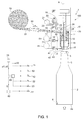
- number 1 indicates a filling device for contact filling an article, hereinafter referred to as container 2, with a pourable product, especially a carbonated food pourable product, beer in the embodiment shown.
- Container 2 comprises, in a known manner,:
- Filling device 1 substantially comprises:
- Tank 13 is filled, in the embodiment shown, with the pourable product.
- Support 20 is movable parallel to axis A between:
- container 2 When support 20 is in the raised operative position, container 2 preferably undergoes the following operations according the so-called contact filling modality:
- Body 10 further comprises:
- fluidic line 19 comprises:
- Valves 22, 23 are arranged along relative ducts 28, 29.
- valves 22, 23 can be selectively set in:
- Valves 22, 23 are set in the respective open positions, during the pressurization step of container 2 ( Figure 3 ), while they are set in the respective closed positions when the vacuum-generation step ( Figure 2 ) and during the de-pressurization step ( Figure 7 ).
- Body 10 further comprises:
- Valve 42 is set in the open position, during the de-pressurization step of container 2, while is set in the closed position while the other operations are carried out on container 2.
- body 10 comprises
- Section 43 is, in particular, interposed between valve 41 and opening 14 along fluidic line 40.
- fluidic line 50 is formed as a derivation of fluidic line 40.
- Section 43 is fluidly connected with opening 14 also when shutter 15 is in the closed position.
- fluidic line 40 opens into opening 14 below the position reached by shutter 15 in the closed position.
- Valve 52 is set in the open position during the vacuum generation step of container 2 ( Figure 2 ); and is set in the closed position ( Figures 1 and 3 to 8 ) during the other operations on container 2.
- Filling device 1 further comprises a control unit 60 (only schematically shown in Figures 1 to 8 ), which is programmed for measuring a quantity associated to the level reached by the pourable product that has been filled inside container 2.
- control unit 60 is programmed for detecting that the pourable product has reached a desired level L ( Figures 6 to 8 ) inside container 2.
- control unit 60 is programmed for measuring a quantity associated to the empty volume V1, V2 ( Figure 5 ) of container 2, i.e. the volume not-filled with pourable product, during the filling of container 2.
- control unit 60 is programmed for associating to empty volume V1, V2, the level reached by the pourable product inside container 2, on the basis of the size of the diameter of neck 5 of container 2.
- control unit 60 is programmed for associating empty volume V2 to the attainment of desired level L of pourable product inside container 2 ( Figures 6 to 8 ).
- V1 will indicate a general value of empty volume greater than value V2 and which is reached before that level of pourable product inside container 2 equals desired level L, i.e. when the level of the pourable product inside container 2 is smaller than desired level L.
- empty volume V2 defines a head-space in neck 5 of container 2 ( Figures 6 to 8 ).
- control unit 60 is programmed to set shutter 15 in the closed position when it has detected that the desired level L has been reached by the pourable product inside container 2.
- Filling device 1 preferably comprises a flow-meter 80, which is arranged along a duct 81 extending between tank 13 and opening 12, and is adapted to measure the flow Q - and, therefore, the quantity - of pourable product filled inside container 2, when shutter 15 is in the open position.
- control unit 60 when control unit 60 has set shutter 15 in the open position,:
- volume V is measured by flow-meter 80 up to when it reaches 80% of desired volume and the level reached is then measured by control unit 60 by measuring empty volume V2, up to when desired level L is reached.
- control unit 60 sets at least one valve (22 in the embodiment shown) in the open position, so as to allow the return of the aeriform - carbon dioxide in the embodiment shown - escaping from the inner volume of container 2 inside collector 21.
- control unit 60 sets both valves 22, 23 in the respective closed position, so as to prevent the return of the aeriform - carbon dioxide in the embodiment shown - escaping from the inner volume of container 2 inside collector 21 ( Figures 5 and 6 ).
- Body 10 of filling device 1 comprises a sensor 70, which is configured to generate a signal associated to the pressure inside empty volume of container 2 and is functionally connected with control unit 60.
- body 10 comprises a fluidic line 71, which extends between section 27 and discharge collector 41.
- Sensor 70 is arranged along fluidic line 71.
- sensor 70 generates a signal associated to the pressure inside ducts 24, 25 - and, therefore, inside the empty volume V2 of container 2 -, when shutter 15 is in the closed position and valves 22, 23 are in respective closed positions.
- sensor 70 is, by a way of example, a piezo-electric sensor.
- filling device 1 comprise a single housing (not-shown) which houses sensor 70 and valve 72.
- body 10 comprises a valve 72, which is arranged along fluidic line 71 and in a position interposed between sensor 70 and discharge collector 41.
- control unit 60 is preferably programmed for selectively moving valve 72, when shutter 15 is in the open position and valves 22, 23 are in respective closed positions, between:
- fluidic line 71 and ducts 24, 25 define a single way for the aeriform contained in the empty volume of container 2, when valves 22, 23 are in respective closed positions.
- the switch of valve 72 from the open position to the closed position causes an increase in the pressure of the aeriform in ducts 24, 25 and empty volume V2 of container 2, due to the fact that the pourable product filling container 2 is reducing the volume available for the aeriform.
- valve 72 from the closed position to the open position causes a decrease in the pressure of the aeriform in ducts 24, 25 and in empty volume V1, V2 of container 2, due to the fact that the switch increases the volume available for that aeriform.
- control unit 60 measures empty volume V1, V2 of container 2 by:
- control unit 60 is programmed for cyclically:
- control unit 60 is programmed for calculating the empty volume on the basis of time interval ⁇ t necessary to register fixed increase p2-p1, where:
- sensor 70 measures an increase from pressure p1 to pressure p2 inside fluidic line 71.
- control unit 60 is programmed for calculating V2, on the basis of:
- Equation (1) can be justified in the following way, on the basis of the assumption that the aeriform contained in ducts 23, 24 and empty volume V2 behaves as a perfect gas, that the variation of temperature of that aeriform are neglectable during time interval ⁇ t, and that both container 2 and pourable product are not compressible.
- control unit 60 which, when executed implements equations (1) to (4).
- Figure 9 further shows the variation of time interval ⁇ t, when the empty volume decreases, and the operation of shutter 15, which is the open position when line 101 assumes value 1 and is in the closed position when line 101 assume value 0.
- Filling device 1 is preferably incorporated in a filling station 100, which substantially comprises:
- Axes A of filling devices are spaced from and parallel axis of rotation of carousel.
- Supports 20 are driven in rotation by carousel, receive relative empty containers 2 at an inlet station (not-shown), convey relative containers 2 along an arc-shaped trajectory, and output filled containers 2 at an outlet station (not-shown).
- each support 20 is arranged in the relative rest position at inlet station and at the outlet station, and moves from the relative rest position to the lowered position and vice-versa along the arc-shaped trajectory.
- Filling station 100 further defines a single tank 13, a single flow-meter 80 and duct 81, and single collectors 41, 51 for all filling devices 1.
- support 20 is in the rest position and mouth 3 of empty container 2 is spaced along axis A from opening 14 and body 10.
- control unit 60 sets shutter 15 and valves 22, 23, 42, 52, 72 in respective closed position.
- support 20 moves along axis A up to reach the operative position ( Figure 2 ), in which mouth 3 of container 2 is pressed and in tight-fluid contact with opening 14 and body 10.
- Control unit 60 sets valve 52 in the open position, so as to create a fluidic connection between vacuum collector 51 and opening 14 and, therefore, between vacuum collector 51 and the inner volume of container 2. As a result, the vacuum is generated inside the inner volume of container 2, so as to prevent the risk of oxidation of the pourable product.
- control unit 60 sets valve 52 in the closed position and sets valves 22, 23 in the respective open positions, while keeping shutter 15 in the closed position ( Figure 3 ).
- the pressurizing gas carbon dioxide in the embodiment shown, flows from collector 21 towards ducts 28, 29, 23, 24, opening 14 and mouth 3, up to reach the inner volume of container 2.
- the inner volume of container 2 is pressurized to the same pressure as the pourable product in tank 13.
- control unit 60 sets shutter 15 in the open position ( Figures 4 to 6 ), so as to fill container 2 with the pourable product.
- the filling of container 2 comprises:
- control unit 60 sets at least one (23) of valves 22, 23 in respective open position and sets shutter 15 in the open position ( Figure 4 ).
- the pourable product can flow from tank 13 to mouth 3 of container 2, thus filling the latter, while the aeriform - carbon dioxide in the embodiment shown - in container 2 escapes from container 2 through mouth 3 and ducts 24, 25 and returns inside collector 21 by one (or both) ducts 28, 29.
- Flow-meter 80 measures the amount of flow Q of the pourable product along duct 81.
- control unit 60 can adjust the filling speed of container 2.
- control unit 60 valves 22, 23 in respective open position, keeps shutter 15 in the open position, and cyclically move valve 72 between the open position ( Figure 6 ) and the closed position ( Figure 5 ).
- the aeriform - carbon dioxide in the embodiment shown - escapes from container 2 through mouth 3 and ducts 24, 25 and is prevented from returning inside collector 21.
- control unit 60 measures empty volume V1, V2 of container 2, and measures the level reached by the pourable product inside container 2 on the basis of the measure of the empty volume.
- control unit 60 cyclically switches valve 72 between the open position ( Figure 5 ) and the closed position ( Figure 6 ).
- sensor 70 detects an increase in the pressure inside ducts 24, 25 - and, therefore, inside empty volume V2 -, when valve 72 is in the closed position.
- sensor 70 detects a sudden decrease in the pressure inside ducts 24, 25 - and, therefore, inside empty volume V1, V2, when control unit 60 sets valve 72 in the open position.
- control unit 60 cyclically:
- control unit 60 measures that desired level L has been reached by pourable product inside container 2, on the basis of the attainment of empty volume V2 and of the size of the diameter of neck 5.
- control unit 60 When control unit 60 detects that the level of pourable product that has filled container 2 equals desired value L, it sets shutter 15 in the closed position ( Figure 6 ) .
- control unit 60 sets valve 42 in the open position, so as to fluidly connect discharge collector with opening 14 and the inner volume of container 2 through fluidic line 40. In this way, the aeriform in container 2 is discharge, up to when the pressure inside container 2 reaches the environment pressure ( Figure 7 ).
- control unit 60 sets valve 42 in the closed position and support 20 moves from the operative position to the rest position, as shown in Figure 8 .
- Filled container 2 is now discharged from support 20.
- control unit 60 is programmed for detecting that pourable product has reached desired level L of filling by measuring empty volume V1, V2 of container 2, during the filling of container 2.
- filling device 1 can fill containers 2 with the desired level L of pourable product, by simply measuring that empty volume V2 has been reached therein, and without requiring the presence of an inductive probe, as in the known solutions discussed in the introductory part of the present description.
- Support 20 moved along a narrower stroke parallel to axis A between the rest position and the operative position, when compared with the known solutions described in the introductory part of the present description.
- filling device 1 requires the same cleaning device as the filling device that fills plastic containers 2.
- Filling device 1 can also be efficiently used for filling container 2 with a broader range of desired levels L than the known filling devices described in the introductory part of the present description.
- Filling device 1 is more similar to filling devices than the known filling devices described in introductory part of the present description and used for filling plastic containers 2 with carbonated products other.
- filling device 1 reduces the manufacturing and supplying cost, when compared with those known solution.
- flow-meter 80 is efficiently used, during the first initial step of filling of container 2, for detecting that a given amount of pourable product has filled container 2 ( Figure 4 ).
- valve 72 is kept in the closed position and one (22) of valves (22, 23) is kept in the open position, so that the aeriform which escapes from the inner volume of container 2 returns inside collector 21.
- control unit 60 sets valves 22, 23 in the closed position and switches valve 72 between the open position and closed position, so as to measure that value V2 of empty volume has been reached and, accordingly, detect that desired level L has been reached ( Figures 5 and 6 ).
- valve 72 is required to switch between the open and the closed position only during the second step of filling, thus correspondingly increasing the life-time of valve 72.
- the aeriform escapes from the inner volume of container 2 inside collector 41 - and is, therefore, not recovered in collector 21 - only during the second step of filling, thus reducing the consumption of carbon dioxide.
- the first step of the filling cycle of container 2 could be not present.
- filling device 1 could use a component other than flow-meter 80 to detect flow Q of pourable product.
- control unit 60 could use interval time ⁇ t for measuring flow Q.
- control unit 60 would be programmed for moving one of valves 22, 23 between the respective open position and the respective closed position and to leave the other valves 22, 23 in the respective open position, so that to cyclically increase and reduce the pressure inside ducts 24, 25 and empty volume V1, V2 of container 2.
Landscapes
- Basic Packing Technique (AREA)
- Filling Of Jars Or Cans And Processes For Cleaning And Sealing Jars (AREA)
Claims (6)
- Ein Verfahren zum Kontaktfüllen zumindest eines Gegenstands (2) mit einem fließfähigen Produkt, umfassend die folgenden Schritte:i) Anordnen einer Mündung (3) des Gegenstands (2) in Kontakt mit einem Füllkörper (10), der eine erste Fluidleitung (11) für das fließfähige Produkt definiert,ii) Befüllen des Gegenstands (2) durch Herstellen einer Fluidverbindung zwischen der ersten Fluidleitung (11) und dem Gegenstand (2), undiii) Messen eines von dem fließfähigen Produkt in dem Gegenstand (2) erreichten Füllstandes (L) während Schritt ii),
wobei Schritt iii) den Schritt iv) des Messens einer ersten physikalischen Größe (V1, V2) in Bezug auf das Leervolumen des Gegenstands (2) umfasst,
wobei Schritt iv) während Schritt ii) durchgeführt wird,
wobei Schritt iv) den Schritt v) des Messens einer zweiten physikalischen Größe (p1, p2) in Bezug auf den Druck in dem Leervolumen umfasst,
wobei Schritt iv) den Schritt vi) des Messens einer dritten physikalischen Größe (p2-p1) in Bezug auf die zeitliche Schwankung des Drucks in dem Leervolumen umfasst,
dadurch gekennzeichnet, dass Schritt vi) den Schritt vii) des Messens einer vierten physikalischen Größe (Δt) in Bezug auf das benötigte Zeitintervall zum Erreichen einer gegebenen Erhöhung (p2-p1) des Drucks in dem Leervolumen während Schritt ii) umfasst,
wobei das Verfahren ferner die folgenden Schritte umfasst:viii) Zulassen des Austretens eines in dem Gegenstand (2) enthaltenen gasförmigen Stoffes entlang einer zweiten Fluidleitung (24, 25) während Schritt ii), undix) Messen der dritten Größe (p1, p2) entlang der zweiten Fluidleitung (24, 25),
wobei Schritt vi) den Schritt x) des zyklischen Unterbrechens der Strömung des gasförmigen Stoffes entlang der zweiten Fluidleitung (24, 25) umfasst. - Das Verfahren gemäß Anspruch 1, dadurch gekennzeichnet, dass Schritt vi) die folgenden Schritte umfasst:xi) fluidisches Isolieren der zweiten Leitung (24, 25) von einem Sammelbehälter (21) für den gasförmigen Stoff, undxii) zyklisches Verbinden der zweiten Leitung (24, 25) mit einem Auslass (41) in fluidischer Weise.
- Das Verfahren gemäß Anspruch 1 oder 2, dadurch gekennzeichnet, dass es einen Schritt xiii) des Messens einer fünften physikalischen Größe (Q) in Bezug auf das Volumen des fließfähigen Produkts, das den Gegenstand (2) befüllt hat, während eines ersten Abschnitts von Schritt ii),
wobei Schritt vi) nach Schritt xiii) und während eines zweiten Abschnitts von Schritt ii) durchgeführt wird. - Eine Füllvorrichtung (1) zum Kontaktfüllen zumindest eines Gegenstands (2) mit einem fließfähigen Produkt, umfassend:- einen Körper (10), der eine erste Fluidleitung (11) für das fließfähige Produkt definiert.- eine Absperrvorrichtung (15), die wahlweise in eine erste Position gesetzt werden kann, in der sie es dem fließfähigen Produkt ermöglicht, von der Fluidleitung (11) in den Gegenstand (2) zu fließen, um den Gegenstand (2) mit dem fließfähigen Produkt zu befüllen, oder in eine zweite Position, in der sie das fließfähige Produkt daran hindert, von der Fluidleitung (11) in den Gegenstand (2) zu fließen, wobei der Gegenstand (2) so ausgeführt ist, dass er in Kontakt mit dem Körper (2) gebracht werden kann, und- eine Steuereinheit (60), die so programmiert ist, dass sie einen von dem fließfähigen Produkt in dem Gegenstand (2) erreichten Füllstand (L) misst, wenn die Absperrvorrichtung (15) sich in der ersten Position befindet,
wobei die Steuereinheit (60) so programmiert ist, dass sie eine erste physikalische Größe (V1, V2) in Bezug auf das Leervolumen des Gegenstands (2) misst, wenn die Absperrvorrichtung (15) sich in der ersten Position befindet, und den Füllstand (L) auf Basis der ersten physikalischen Größe (V1, V2) misst,
wobei die Füllvorrichtung (1) einen Sensor (70) umfasst, der so ausgelegt ist, dass er ein mit einer zweiten physikalischen Größe (p1, p2) in Bezug auf den Druck in dem Leervolumen verknüpftes Signal erzeugt, wobei der Sensor (70) funktional mit der Steuereinheit (60) verbunden ist,
wobei die Steuereinheit (60) so programmiert ist, dass sie die erste physikalische Größe (V1, V2) auch auf Basis der zweiten physikalischen Größe (p1, p2) misst,
wobei die Füllvorrichtung (1) ferner eine zweite Fluidleitung (24, 25) umfasst, die fluidisch mit dem Innenvolumen des Gegenstands (2) verbindbar ist und das Austreten des gasförmigen Stoffes zulassen kann, wenn die Absperrvorrichtung (15) sich in der ersten Position befindet, wobei der Sensor (70) entlang der zweiten Fluidleitung (24, 25) angeordnet ist,
dadurch gekennzeichnet, dass sie ein erstes Ventil (72) umfasst, das entlang der zweiten Leitung (24, 25) eingebaut ist und wahlweise beweglich ist zwischen:- einer ersten Position, in der es das Strömen des gasförmigen Stoffes entlang der zweiten Fluidleitung (24, 25) zulässt, oder- einer zweiten Position, in der es das Strömen des gasförmigen Stoffes entlang der zweiten Fluidleitung (24, 25) verhindert, um den Druck entlang der zweiten Fluidleitung (24, 25) und das Leervolumen zyklisch zur erhöhen und zu senken,
wobei das erste Ventil (72) so ansteuerbar ist, dass es das Strömen des gasförmigen Stoffes für ein Zeitintervall (Δt) unterbricht, das nötig ist, um eine gegebene Erhöhung (p1-p2) des Drucks in dem Leervolumen zu erreichen,
wobei die Steuereinheit (60) so programmiert ist, dass sie die erste physikalische Größe (V1, V2) auch auf Basis des Zeitintervalls (Δt) misst. - Die Füllvorrichtung gemäß Anspruch 4, dadurch gekennzeichnet, dass sie umfasst:- einen Sammelbehälter (21) für den gasförmigen Stoff,- zumindest ein zweites Ventil (22, 23), das wahlweise in eine erste Position gesetzt werden kann, in der es den Sammelbehälter (21) und die zweite Fluidleitung (24, 25) fluidisch miteinander verbindet, oder in eine zweite Position, in der es den Sammelbehälter (21) und die zweite Fluidleitung (24, 25) fluidisch voneinander isoliert,- einen Auslass (41), der fluidisch mit dem Gegenstand (2) verbindbar ist, wenn die Absperrvorrichtung (15) sich in der zweiten Position befindet und wenn der Gegenstand (2) sich während der Anwendung in Kontakt mit dem Füllkörper befindet,- eine dritte Fluidleitung (71), die sich zwischen dem Auslass (41) und der zweiten Fluidleitung (24, 25) erstreckt,
wobei die Steuereinheit (60) so programmiert ist, dass sie- das erste Ventil (72) in die erste Position setzt,- das zumindest eine zweite Ventil (22, 23) in die zweite Position setzt, und- die Absperrvorrichtung (15) in die erste Position setzt, so dass der gasförmige Stoff entlang der dritten Fluidleitung (71) zu dem Auslass (41) gefördert wird, wenn der Gegenstand (2) während der Anwendung mit dem fließfähigen Produkt befüllt wird. - Die Füllvorrichtung gemäß Anspruch 4 oder 5, dadurch gekennzeichnet, dass sie umfasst:- einen Durchflusssensor (80) zum Messen einer dritten physikalischen Größe (Q) in Bezug auf die Menge des fließfähigen Produkts, das während der Anwendung den Gegenstand (2) befüllt hat, wenn die Absperrvorrichtung (15) sich während der Anwendung in der ersten Position befindet,
wobei die Steuereinheit (60) so programmiert ist, dass sie das Volumen des fließfähigen Produkts, das den Gegenstand (2) während eines ersten Abschnitts des Zeitintervalls, in dem sich die Absperrvorrichtung (15) während der Anwendung in der ersten Position befindet, misst, wobei die Steuereinheit (60) so programmiert ist, dass sie die erste physikalische Größe (V1, V2) während eines zweiten, dem ersten Teil nachfolgenden Abschnitts des Zeitintervalls, in dem die Absperrvorrichtung (15) sich während der Anwendung in der ersten Position befindet, misst,
wobei die Steuereinheit (60) so programmiert ist, dass sie zumindest ein zweites Ventil (22, 23) während des ersten Abschnitts in die erste Position und während das zweiten Abschnitts in die zweite Position setzt.
Priority Applications (1)
| Application Number | Priority Date | Filing Date | Title |
|---|---|---|---|
| EP14170711.7A EP2949618B1 (de) | 2014-05-30 | 2014-05-30 | Verfahren und Vorrichtung zum Kontaktfüllen eines Artikels mit einem fliessfähigen Produkt |
Applications Claiming Priority (1)
| Application Number | Priority Date | Filing Date | Title |
|---|---|---|---|
| EP14170711.7A EP2949618B1 (de) | 2014-05-30 | 2014-05-30 | Verfahren und Vorrichtung zum Kontaktfüllen eines Artikels mit einem fliessfähigen Produkt |
Publications (2)
| Publication Number | Publication Date |
|---|---|
| EP2949618A1 EP2949618A1 (de) | 2015-12-02 |
| EP2949618B1 true EP2949618B1 (de) | 2016-08-31 |
Family
ID=51162421
Family Applications (1)
| Application Number | Title | Priority Date | Filing Date |
|---|---|---|---|
| EP14170711.7A Not-in-force EP2949618B1 (de) | 2014-05-30 | 2014-05-30 | Verfahren und Vorrichtung zum Kontaktfüllen eines Artikels mit einem fliessfähigen Produkt |
Country Status (1)
| Country | Link |
|---|---|
| EP (1) | EP2949618B1 (de) |
Cited By (3)
| Publication number | Priority date | Publication date | Assignee | Title |
|---|---|---|---|---|
| EP3326962A1 (de) * | 2016-11-24 | 2018-05-30 | Sidel Participations | Verfahren und füllvorrichtung zum kontaktfüllen eines artikels mit einem schüttfähigen produkt |
| EP3326961A1 (de) | 2016-11-24 | 2018-05-30 | Sidel Participations | Verfahren und füllvorrichtung zum kontaktfüllen eines artikels mit einem schüttfähigen produkt |
| WO2023110121A1 (en) * | 2021-12-17 | 2023-06-22 | Sidel Participations | System and method for monitoring a process for filling containers, corresponding filling device and filling machine |
Families Citing this family (1)
| Publication number | Priority date | Publication date | Assignee | Title |
|---|---|---|---|---|
| EP3202704B1 (de) | 2016-02-08 | 2018-09-26 | Sidel Participations | Verfahren zur erkennung des defekten zustands eines produkts, das mit einem giessbaren produkt kontaktbefüllt werden soll, und füllvorrichtung |
Family Cites Families (4)
| Publication number | Priority date | Publication date | Assignee | Title |
|---|---|---|---|---|
| JPH07267297A (ja) * | 1994-03-30 | 1995-10-17 | Mitsubishi Heavy Ind Ltd | 充填バルブ |
| JP2633820B2 (ja) * | 1995-06-16 | 1997-07-23 | ボッシュ包装機株式会社 | 液体の圧力充填方法 |
| DE10306751B4 (de) * | 2003-02-17 | 2005-06-09 | Endress + Hauser Flowtec Ag, Reinach | Vorrichtung zum Abfüllen eines Mediums |
| WO2012137317A1 (ja) * | 2011-04-06 | 2012-10-11 | 三菱重工食品包装機械株式会社 | 回転式充填機及び回転式充填機の充填量演算方法 |
-
2014
- 2014-05-30 EP EP14170711.7A patent/EP2949618B1/de not_active Not-in-force
Cited By (5)
| Publication number | Priority date | Publication date | Assignee | Title |
|---|---|---|---|---|
| EP3326962A1 (de) * | 2016-11-24 | 2018-05-30 | Sidel Participations | Verfahren und füllvorrichtung zum kontaktfüllen eines artikels mit einem schüttfähigen produkt |
| EP3326961A1 (de) | 2016-11-24 | 2018-05-30 | Sidel Participations | Verfahren und füllvorrichtung zum kontaktfüllen eines artikels mit einem schüttfähigen produkt |
| WO2018095715A1 (en) * | 2016-11-24 | 2018-05-31 | Sidel Participations | Method and filling device for contact filling an article with pourable product |
| WO2018095714A1 (en) | 2016-11-24 | 2018-05-31 | Sidel Participations | Method and filling device for contact filling an article with pourable product |
| WO2023110121A1 (en) * | 2021-12-17 | 2023-06-22 | Sidel Participations | System and method for monitoring a process for filling containers, corresponding filling device and filling machine |
Also Published As
| Publication number | Publication date |
|---|---|
| EP2949618A1 (de) | 2015-12-02 |
Similar Documents
| Publication | Publication Date | Title |
|---|---|---|
| EP2949618B1 (de) | Verfahren und Vorrichtung zum Kontaktfüllen eines Artikels mit einem fliessfähigen Produkt | |
| US9963335B2 (en) | Method and system for filling containers | |
| CN106829836B (zh) | 用于填充机的填充装置 | |
| US20130105041A1 (en) | Filling element, method and filling system for filling containers | |
| US9695028B2 (en) | Filling unit and method for filling an article with a pourable product | |
| WO2018100004A1 (en) | Modular machine for filling bottles and cans. | |
| WO2015055397A1 (en) | A method for a filling valve, and a filling valve system | |
| CN112537741A (zh) | 用于用填充产品填充容器的方法及设备 | |
| US4254804A (en) | Filling device for filling containers | |
| CN108996452A (zh) | 高效负压灌装装置 | |
| US6142169A (en) | Sterile tank venting system for a filling machine | |
| JP4008574B2 (ja) | 液体充填装置及び方法 | |
| CN111003230B (zh) | 一种负压法非接触式液体灌装控制液位方法 | |
| CN110979771B (zh) | 一种非接触式液体灌装装置 | |
| WO2010131271A1 (en) | Filling method and valve | |
| GB1151245A (en) | Improvements in Apparatus for Processing Beer Kegs or like Containers | |
| EP3326961A1 (de) | Verfahren und füllvorrichtung zum kontaktfüllen eines artikels mit einem schüttfähigen produkt | |
| KR101522928B1 (ko) | 압력센서를 구비한 고속 유체 회전 충진시스템 | |
| US20170166429A1 (en) | Machine and method for filling containers with pourable product | |
| EP1156965B1 (de) | Verfahren und vorrichtung zum dosieren von flüssigkeiten | |
| EP3326962A1 (de) | Verfahren und füllvorrichtung zum kontaktfüllen eines artikels mit einem schüttfähigen produkt | |
| EP2942288B1 (de) | Füllmaschine, insbesondere vom wägefülltyp, zum befüllen von behältern, wie etwa fässer, flaschen, dosen und/oder dergleichen, und zugehöriges füllverfahren | |
| EP3473588A1 (de) | Vorrichtung und verfahren zum füllen von behältern mit einem fliessfähigen produkt unter druck | |
| EP3421411B1 (de) | Fülleinheit zum füllen eines artikels mit einem fliessfähigen produkt | |
| EP3202704B1 (de) | Verfahren zur erkennung des defekten zustands eines produkts, das mit einem giessbaren produkt kontaktbefüllt werden soll, und füllvorrichtung |
Legal Events
| Date | Code | Title | Description |
|---|---|---|---|
| 17P | Request for examination filed |
Effective date: 20150227 |
|
| AK | Designated contracting states |
Kind code of ref document: A1 Designated state(s): AL AT BE BG CH CY CZ DE DK EE ES FI FR GB GR HR HU IE IS IT LI LT LU LV MC MK MT NL NO PL PT RO RS SE SI SK SM TR |
|
| AX | Request for extension of the european patent |
Extension state: BA ME |
|
| PUAI | Public reference made under article 153(3) epc to a published international application that has entered the european phase |
Free format text: ORIGINAL CODE: 0009012 |
|
| GRAP | Despatch of communication of intention to grant a patent |
Free format text: ORIGINAL CODE: EPIDOSNIGR1 |
|
| GRAP | Despatch of communication of intention to grant a patent |
Free format text: ORIGINAL CODE: EPIDOSNIGR1 |
|
| INTG | Intention to grant announced |
Effective date: 20160301 |
|
| INTG | Intention to grant announced |
Effective date: 20160315 |
|
| GRAS | Grant fee paid |
Free format text: ORIGINAL CODE: EPIDOSNIGR3 |
|
| GRAA | (expected) grant |
Free format text: ORIGINAL CODE: 0009210 |
|
| AK | Designated contracting states |
Kind code of ref document: B1 Designated state(s): AL AT BE BG CH CY CZ DE DK EE ES FI FR GB GR HR HU IE IS IT LI LT LU LV MC MK MT NL NO PL PT RO RS SE SI SK SM TR |
|
| REG | Reference to a national code |
Ref country code: CH Ref legal event code: EP Ref country code: GB Ref legal event code: FG4D |
|
| REG | Reference to a national code |
Ref country code: IE Ref legal event code: FG4D |
|
| REG | Reference to a national code |
Ref country code: DE Ref legal event code: R096 Ref document number: 602014003350 Country of ref document: DE |
|
| REG | Reference to a national code |
Ref country code: AT Ref legal event code: REF Ref document number: 824805 Country of ref document: AT Kind code of ref document: T Effective date: 20161015 |
|
| REG | Reference to a national code |
Ref country code: LT Ref legal event code: MG4D |
|
| REG | Reference to a national code |
Ref country code: NL Ref legal event code: MP Effective date: 20160831 |
|
| REG | Reference to a national code |
Ref country code: AT Ref legal event code: MK05 Ref document number: 824805 Country of ref document: AT Kind code of ref document: T Effective date: 20160831 |
|
| PG25 | Lapsed in a contracting state [announced via postgrant information from national office to epo] |
Ref country code: RS Free format text: LAPSE BECAUSE OF FAILURE TO SUBMIT A TRANSLATION OF THE DESCRIPTION OR TO PAY THE FEE WITHIN THE PRESCRIBED TIME-LIMIT Effective date: 20160831 Ref country code: LT Free format text: LAPSE BECAUSE OF FAILURE TO SUBMIT A TRANSLATION OF THE DESCRIPTION OR TO PAY THE FEE WITHIN THE PRESCRIBED TIME-LIMIT Effective date: 20160831 Ref country code: FI Free format text: LAPSE BECAUSE OF FAILURE TO SUBMIT A TRANSLATION OF THE DESCRIPTION OR TO PAY THE FEE WITHIN THE PRESCRIBED TIME-LIMIT Effective date: 20160831 Ref country code: NO Free format text: LAPSE BECAUSE OF FAILURE TO SUBMIT A TRANSLATION OF THE DESCRIPTION OR TO PAY THE FEE WITHIN THE PRESCRIBED TIME-LIMIT Effective date: 20161130 Ref country code: HR Free format text: LAPSE BECAUSE OF FAILURE TO SUBMIT A TRANSLATION OF THE DESCRIPTION OR TO PAY THE FEE WITHIN THE PRESCRIBED TIME-LIMIT Effective date: 20160831 |
|
| PG25 | Lapsed in a contracting state [announced via postgrant information from national office to epo] |
Ref country code: GR Free format text: LAPSE BECAUSE OF FAILURE TO SUBMIT A TRANSLATION OF THE DESCRIPTION OR TO PAY THE FEE WITHIN THE PRESCRIBED TIME-LIMIT Effective date: 20161201 Ref country code: NL Free format text: LAPSE BECAUSE OF FAILURE TO SUBMIT A TRANSLATION OF THE DESCRIPTION OR TO PAY THE FEE WITHIN THE PRESCRIBED TIME-LIMIT Effective date: 20160831 Ref country code: SE Free format text: LAPSE BECAUSE OF FAILURE TO SUBMIT A TRANSLATION OF THE DESCRIPTION OR TO PAY THE FEE WITHIN THE PRESCRIBED TIME-LIMIT Effective date: 20160831 Ref country code: AT Free format text: LAPSE BECAUSE OF FAILURE TO SUBMIT A TRANSLATION OF THE DESCRIPTION OR TO PAY THE FEE WITHIN THE PRESCRIBED TIME-LIMIT Effective date: 20160831 Ref country code: ES Free format text: LAPSE BECAUSE OF FAILURE TO SUBMIT A TRANSLATION OF THE DESCRIPTION OR TO PAY THE FEE WITHIN THE PRESCRIBED TIME-LIMIT Effective date: 20160831 Ref country code: LV Free format text: LAPSE BECAUSE OF FAILURE TO SUBMIT A TRANSLATION OF THE DESCRIPTION OR TO PAY THE FEE WITHIN THE PRESCRIBED TIME-LIMIT Effective date: 20160831 |
|
| REG | Reference to a national code |
Ref country code: FR Ref legal event code: PLFP Year of fee payment: 4 |
|
| PG25 | Lapsed in a contracting state [announced via postgrant information from national office to epo] |
Ref country code: EE Free format text: LAPSE BECAUSE OF FAILURE TO SUBMIT A TRANSLATION OF THE DESCRIPTION OR TO PAY THE FEE WITHIN THE PRESCRIBED TIME-LIMIT Effective date: 20160831 Ref country code: RO Free format text: LAPSE BECAUSE OF FAILURE TO SUBMIT A TRANSLATION OF THE DESCRIPTION OR TO PAY THE FEE WITHIN THE PRESCRIBED TIME-LIMIT Effective date: 20160831 |
|
| PG25 | Lapsed in a contracting state [announced via postgrant information from national office to epo] |
Ref country code: CZ Free format text: LAPSE BECAUSE OF FAILURE TO SUBMIT A TRANSLATION OF THE DESCRIPTION OR TO PAY THE FEE WITHIN THE PRESCRIBED TIME-LIMIT Effective date: 20160831 Ref country code: BG Free format text: LAPSE BECAUSE OF FAILURE TO SUBMIT A TRANSLATION OF THE DESCRIPTION OR TO PAY THE FEE WITHIN THE PRESCRIBED TIME-LIMIT Effective date: 20161130 Ref country code: SM Free format text: LAPSE BECAUSE OF FAILURE TO SUBMIT A TRANSLATION OF THE DESCRIPTION OR TO PAY THE FEE WITHIN THE PRESCRIBED TIME-LIMIT Effective date: 20160831 Ref country code: SK Free format text: LAPSE BECAUSE OF FAILURE TO SUBMIT A TRANSLATION OF THE DESCRIPTION OR TO PAY THE FEE WITHIN THE PRESCRIBED TIME-LIMIT Effective date: 20160831 Ref country code: PT Free format text: LAPSE BECAUSE OF FAILURE TO SUBMIT A TRANSLATION OF THE DESCRIPTION OR TO PAY THE FEE WITHIN THE PRESCRIBED TIME-LIMIT Effective date: 20170102 Ref country code: BE Free format text: LAPSE BECAUSE OF FAILURE TO SUBMIT A TRANSLATION OF THE DESCRIPTION OR TO PAY THE FEE WITHIN THE PRESCRIBED TIME-LIMIT Effective date: 20160831 Ref country code: PL Free format text: LAPSE BECAUSE OF FAILURE TO SUBMIT A TRANSLATION OF THE DESCRIPTION OR TO PAY THE FEE WITHIN THE PRESCRIBED TIME-LIMIT Effective date: 20160831 Ref country code: DK Free format text: LAPSE BECAUSE OF FAILURE TO SUBMIT A TRANSLATION OF THE DESCRIPTION OR TO PAY THE FEE WITHIN THE PRESCRIBED TIME-LIMIT Effective date: 20160831 |
|
| REG | Reference to a national code |
Ref country code: DE Ref legal event code: R097 Ref document number: 602014003350 Country of ref document: DE |
|
| PLBE | No opposition filed within time limit |
Free format text: ORIGINAL CODE: 0009261 |
|
| STAA | Information on the status of an ep patent application or granted ep patent |
Free format text: STATUS: NO OPPOSITION FILED WITHIN TIME LIMIT |
|
| 26N | No opposition filed |
Effective date: 20170601 |
|
| PG25 | Lapsed in a contracting state [announced via postgrant information from national office to epo] |
Ref country code: LU Free format text: LAPSE BECAUSE OF NON-PAYMENT OF DUE FEES Effective date: 20170531 Ref country code: SI Free format text: LAPSE BECAUSE OF FAILURE TO SUBMIT A TRANSLATION OF THE DESCRIPTION OR TO PAY THE FEE WITHIN THE PRESCRIBED TIME-LIMIT Effective date: 20160831 |
|
| REG | Reference to a national code |
Ref country code: CH Ref legal event code: PL |
|
| PG25 | Lapsed in a contracting state [announced via postgrant information from national office to epo] |
Ref country code: MC Free format text: LAPSE BECAUSE OF FAILURE TO SUBMIT A TRANSLATION OF THE DESCRIPTION OR TO PAY THE FEE WITHIN THE PRESCRIBED TIME-LIMIT Effective date: 20160831 |
|
| REG | Reference to a national code |
Ref country code: IE Ref legal event code: MM4A |
|
| PG25 | Lapsed in a contracting state [announced via postgrant information from national office to epo] |
Ref country code: CH Free format text: LAPSE BECAUSE OF NON-PAYMENT OF DUE FEES Effective date: 20170531 Ref country code: LI Free format text: LAPSE BECAUSE OF NON-PAYMENT OF DUE FEES Effective date: 20170531 |
|
| PG25 | Lapsed in a contracting state [announced via postgrant information from national office to epo] |
Ref country code: LU Free format text: LAPSE BECAUSE OF NON-PAYMENT OF DUE FEES Effective date: 20170530 |
|
| REG | Reference to a national code |
Ref country code: FR Ref legal event code: PLFP Year of fee payment: 5 |
|
| PG25 | Lapsed in a contracting state [announced via postgrant information from national office to epo] |
Ref country code: IE Free format text: LAPSE BECAUSE OF NON-PAYMENT OF DUE FEES Effective date: 20170530 |
|
| PG25 | Lapsed in a contracting state [announced via postgrant information from national office to epo] |
Ref country code: MT Free format text: LAPSE BECAUSE OF NON-PAYMENT OF DUE FEES Effective date: 20170530 |
|
| PG25 | Lapsed in a contracting state [announced via postgrant information from national office to epo] |
Ref country code: AL Free format text: LAPSE BECAUSE OF FAILURE TO SUBMIT A TRANSLATION OF THE DESCRIPTION OR TO PAY THE FEE WITHIN THE PRESCRIBED TIME-LIMIT Effective date: 20160831 |
|
| GBPC | Gb: european patent ceased through non-payment of renewal fee |
Effective date: 20180530 |
|
| PG25 | Lapsed in a contracting state [announced via postgrant information from national office to epo] |
Ref country code: GB Free format text: LAPSE BECAUSE OF NON-PAYMENT OF DUE FEES Effective date: 20180530 |
|
| PG25 | Lapsed in a contracting state [announced via postgrant information from national office to epo] |
Ref country code: HU Free format text: LAPSE BECAUSE OF FAILURE TO SUBMIT A TRANSLATION OF THE DESCRIPTION OR TO PAY THE FEE WITHIN THE PRESCRIBED TIME-LIMIT; INVALID AB INITIO Effective date: 20140530 |
|
| PG25 | Lapsed in a contracting state [announced via postgrant information from national office to epo] |
Ref country code: CY Free format text: LAPSE BECAUSE OF FAILURE TO SUBMIT A TRANSLATION OF THE DESCRIPTION OR TO PAY THE FEE WITHIN THE PRESCRIBED TIME-LIMIT Effective date: 20160831 |
|
| PG25 | Lapsed in a contracting state [announced via postgrant information from national office to epo] |
Ref country code: MK Free format text: LAPSE BECAUSE OF FAILURE TO SUBMIT A TRANSLATION OF THE DESCRIPTION OR TO PAY THE FEE WITHIN THE PRESCRIBED TIME-LIMIT Effective date: 20160831 |
|
| PG25 | Lapsed in a contracting state [announced via postgrant information from national office to epo] |
Ref country code: TR Free format text: LAPSE BECAUSE OF FAILURE TO SUBMIT A TRANSLATION OF THE DESCRIPTION OR TO PAY THE FEE WITHIN THE PRESCRIBED TIME-LIMIT Effective date: 20160831 |
|
| PG25 | Lapsed in a contracting state [announced via postgrant information from national office to epo] |
Ref country code: IS Free format text: LAPSE BECAUSE OF FAILURE TO SUBMIT A TRANSLATION OF THE DESCRIPTION OR TO PAY THE FEE WITHIN THE PRESCRIBED TIME-LIMIT Effective date: 20161231 |
|
| PGFP | Annual fee paid to national office [announced via postgrant information from national office to epo] |
Ref country code: IT Payment date: 20210422 Year of fee payment: 8 Ref country code: FR Payment date: 20210421 Year of fee payment: 8 Ref country code: DE Payment date: 20210421 Year of fee payment: 8 |
|
| REG | Reference to a national code |
Ref country code: DE Ref legal event code: R119 Ref document number: 602014003350 Country of ref document: DE |
|
| PG25 | Lapsed in a contracting state [announced via postgrant information from national office to epo] |
Ref country code: FR Free format text: LAPSE BECAUSE OF NON-PAYMENT OF DUE FEES Effective date: 20220531 |
|
| PG25 | Lapsed in a contracting state [announced via postgrant information from national office to epo] |
Ref country code: DE Free format text: LAPSE BECAUSE OF NON-PAYMENT OF DUE FEES Effective date: 20221201 |
|
| PG25 | Lapsed in a contracting state [announced via postgrant information from national office to epo] |
Ref country code: IT Free format text: LAPSE BECAUSE OF NON-PAYMENT OF DUE FEES Effective date: 20220530 |