EP2949524A1 - Aircraft brake system testing methods - Google Patents
Aircraft brake system testing methods Download PDFInfo
- Publication number
- EP2949524A1 EP2949524A1 EP15168145.9A EP15168145A EP2949524A1 EP 2949524 A1 EP2949524 A1 EP 2949524A1 EP 15168145 A EP15168145 A EP 15168145A EP 2949524 A1 EP2949524 A1 EP 2949524A1
- Authority
- EP
- European Patent Office
- Prior art keywords
- brake
- actuator
- testing method
- electromechanical
- electromechanical actuator
- Prior art date
- Legal status (The legal status is an assumption and is not a legal conclusion. Google has not performed a legal analysis and makes no representation as to the accuracy of the status listed.)
- Granted
Links
Images

Classifications
-
- B—PERFORMING OPERATIONS; TRANSPORTING
- B60—VEHICLES IN GENERAL
- B60T—VEHICLE BRAKE CONTROL SYSTEMS OR PARTS THEREOF; BRAKE CONTROL SYSTEMS OR PARTS THEREOF, IN GENERAL; ARRANGEMENT OF BRAKING ELEMENTS ON VEHICLES IN GENERAL; PORTABLE DEVICES FOR PREVENTING UNWANTED MOVEMENT OF VEHICLES; VEHICLE MODIFICATIONS TO FACILITATE COOLING OF BRAKES
- B60T17/00—Component parts, details, or accessories of power brake systems not covered by groups B60T8/00, B60T13/00 or B60T15/00, or presenting other characteristic features
- B60T17/18—Safety devices; Monitoring
- B60T17/22—Devices for monitoring or checking brake systems; Signal devices
- B60T17/221—Procedure or apparatus for checking or keeping in a correct functioning condition of brake systems
-
- B—PERFORMING OPERATIONS; TRANSPORTING
- B60—VEHICLES IN GENERAL
- B60T—VEHICLE BRAKE CONTROL SYSTEMS OR PARTS THEREOF; BRAKE CONTROL SYSTEMS OR PARTS THEREOF, IN GENERAL; ARRANGEMENT OF BRAKING ELEMENTS ON VEHICLES IN GENERAL; PORTABLE DEVICES FOR PREVENTING UNWANTED MOVEMENT OF VEHICLES; VEHICLE MODIFICATIONS TO FACILITATE COOLING OF BRAKES
- B60T8/00—Arrangements for adjusting wheel-braking force to meet varying vehicular or ground-surface conditions, e.g. limiting or varying distribution of braking force
- B60T8/17—Using electrical or electronic regulation means to control braking
- B60T8/1701—Braking or traction control means specially adapted for particular types of vehicles
- B60T8/1703—Braking or traction control means specially adapted for particular types of vehicles for aircrafts
-
- B—PERFORMING OPERATIONS; TRANSPORTING
- B60—VEHICLES IN GENERAL
- B60T—VEHICLE BRAKE CONTROL SYSTEMS OR PARTS THEREOF; BRAKE CONTROL SYSTEMS OR PARTS THEREOF, IN GENERAL; ARRANGEMENT OF BRAKING ELEMENTS ON VEHICLES IN GENERAL; PORTABLE DEVICES FOR PREVENTING UNWANTED MOVEMENT OF VEHICLES; VEHICLE MODIFICATIONS TO FACILITATE COOLING OF BRAKES
- B60T8/00—Arrangements for adjusting wheel-braking force to meet varying vehicular or ground-surface conditions, e.g. limiting or varying distribution of braking force
- B60T8/32—Arrangements for adjusting wheel-braking force to meet varying vehicular or ground-surface conditions, e.g. limiting or varying distribution of braking force responsive to a speed condition, e.g. acceleration or deceleration
- B60T8/88—Arrangements for adjusting wheel-braking force to meet varying vehicular or ground-surface conditions, e.g. limiting or varying distribution of braking force responsive to a speed condition, e.g. acceleration or deceleration with failure responsive means, i.e. means for detecting and indicating faulty operation of the speed responsive control means
- B60T8/885—Arrangements for adjusting wheel-braking force to meet varying vehicular or ground-surface conditions, e.g. limiting or varying distribution of braking force responsive to a speed condition, e.g. acceleration or deceleration with failure responsive means, i.e. means for detecting and indicating faulty operation of the speed responsive control means using electrical circuitry
-
- B—PERFORMING OPERATIONS; TRANSPORTING
- B64—AIRCRAFT; AVIATION; COSMONAUTICS
- B64C—AEROPLANES; HELICOPTERS
- B64C25/00—Alighting gear
- B64C25/32—Alighting gear characterised by elements which contact the ground or similar surface
- B64C25/42—Arrangement or adaptation of brakes
-
- B—PERFORMING OPERATIONS; TRANSPORTING
- B64—AIRCRAFT; AVIATION; COSMONAUTICS
- B64C—AEROPLANES; HELICOPTERS
- B64C25/00—Alighting gear
- B64C25/32—Alighting gear characterised by elements which contact the ground or similar surface
- B64C25/42—Arrangement or adaptation of brakes
- B64C25/44—Actuating mechanisms
-
- B—PERFORMING OPERATIONS; TRANSPORTING
- B60—VEHICLES IN GENERAL
- B60T—VEHICLE BRAKE CONTROL SYSTEMS OR PARTS THEREOF; BRAKE CONTROL SYSTEMS OR PARTS THEREOF, IN GENERAL; ARRANGEMENT OF BRAKING ELEMENTS ON VEHICLES IN GENERAL; PORTABLE DEVICES FOR PREVENTING UNWANTED MOVEMENT OF VEHICLES; VEHICLE MODIFICATIONS TO FACILITATE COOLING OF BRAKES
- B60T2270/00—Further aspects of brake control systems not otherwise provided for
- B60T2270/40—Failsafe aspects of brake control systems
- B60T2270/406—Test-mode; Self-diagnosis
Definitions
- the present disclosure relates to aircraft wheel and brake assemblies, and more specifically, to testing of aircraft braking systems.
- Aircraft typically utilize landing gear including one or more wheel assemblies.
- wheel assemblies include braking systems which apply braking force to the wheels to assist in decelerating and/or steering the plane during landing or rejected take off (RTO) events. Failure of such braking systems may result in accidents, including runway excursions and collisions with objects, including ground equipment and other aircraft. Undesired and/or uncommanded braking may also result in other aircraft malfunctions.
- RTO rejected take off
- a method for testing the operation of an aircraft braking system comprises at least partially actuating a brake actuator attached to a brake assembly comprising a brake stack, discontinuing actuation to the brake actuator, determining the actuation level of the brake actuator, and evaluating braking performance.
- the brake assembly may comprise one or more electromechanical actuators. Determining the actuation level of the brake actuator comprises receiving a signal from a position detector of the brake actuator. Evaluating braking performance may comprise comparing the actuation level of the brake actuator to a predetermined value. In various embodiments, the difference between the actuation level and a predetermined level may be between about 0.05 inches and 0.2 inches (between about 1 millimeter and 20 millimeters).
- Another method for testing the operation of an aircraft braking system comprises applying a predetermined electrical energy level to an electromechanical actuator attached to a brake assembly comprising a brake stack, discontinuing electrical energy to the electromechanical actuator, measuring the electrical voltage from a motor of the electromechanical actuator, and evaluating braking performance.
- the brake assembly may comprise four electromechanical actuators.
- Evaluating braking performance may comprise comparing the voltage produced by the motor to a predetermined value. In various embodiments, the difference between the voltage produced by the motor and the predetermined value may be between about 1 volt and 600 volts.
- any reference to singular includes plural embodiments, and any reference to more than one component or step may include a singular embodiment or step.
- Surface shading lines may be used throughout the figures to denote different parts but not necessarily to denote the same or different materials.
- electrical energy is referenced throughout the disclosure and exemplary embodiments, electrical energy is just one exemplary type of electrical parameter such as voltage, current, power, etc. that represents measurable electrical values or phenomena that characterize the behavior of electronic circuits, components, or semiconductors. Any electrical parameter may be substituted in place of electrical energy as would be understood by one of ordinary skill in the applicable art.
- Wheel and brake system 10 may comprise, for example, a brake assembly 11.
- brake assembly 11 may be coupled to an axle 15 of a wheel 12.
- brake assembly 11 may exert force against one or more components of wheel 12 to reduce the speed of an aircraft.
- brake assembly 11 may comprise a brake stack 27.
- brake stack 27 may comprise components that interface with both wheel 12 and brake assembly 11.
- brake stack 27 may be configured such that when force is applied, brake stack 27 acts to apply force to wheel 12 and reduce the speed of the aircraft.
- Brake assembly 11 may further comprise, for example, one or more brake actuators 36.
- brake actuators 36 may be configured such that in response to an operator activating a control (e.g., depresses a brake pedal), brake actuators 36 laterally compress brake stack 27 which, in turn, resist rotation of wheel 12 and thus reduces the speed of the aircraft.
- Brake actuator 36 may comprise, for example, an electromechanical brake actuator.
- a predetermined level of electrical energy may be applied to an electromechanical actuator such as brake actuator 36, resulting in a predetermined actuation level.
- brake actuator 36 may comprise a hydraulic actuator. Hydraulic actuator 36 may, for example, be actuated by applying hydraulic presser to brake actuator 36.
- brake actuator 36 may comprise a hybrid electromechanical-hydraulic actuator. Any type of actuator is within the scope of the present invention.
- brake actuator 36 may comprise a ram 35.
- actuation of brake actuator 36 which may cause ram 35 to change position and extend laterally.
- ram 35 may extend towards and apply force to brake stack 27, compressing the stack and reducing the speed of the aircraft.
- Brake actuator 36 may comprise, for example, an electric motor 50.
- electric motor 50 is coupled to ram 35 such that applying electrical energy to the motor causes ram 35 to extend towards and apply force to brake stack 27.
- rotation from electric motor 50 may be translated to ram 35 by gearing, including various ball screws and/or screw gears. Any manner of translating rotation from electric motor 50 to linear motion of ram 35 is within the scope of the present disclosure.
- a hydraulic brake actuator 36 may convert hydraulic pressure applied to the actuator to linear or angular force to ram 35.
- ram 35 in response actuation being discontinued to brake actuator 36, ram 35 may be retracted linearly away from brake stack 27.
- brake stack 27 may comprise a configuration that exerts a restorative force against ram 35, such that ram 35 is pushed back and away from brake stack 27 when actuation is discontinued.
- discontinuing actuation may comprise discontinuing the application of electrical energy, hydraulic pressure, or any combination of both to brake actuator 36.
- Components of brake actuator 36 may fail such that brake stack 27 is at least partially engaged when no electrical energy is being applied to brake actuator 36. For example, after electrical energy is applied and discontinued, ram 35 may remain in an extended position. Stated another way, ram 35 may "stick" such that it continues to provide force to brake stack 27 after electrical energy is discontinued. This scenario may cause unwanted and/or uncommanded braking.
- brake system test method 200 may be employed to determine if one or more brake actuators 36 are operating within predetermined operating parameters and therefore are less likely to cause undesired braking.
- brake system test method 200 may be applied to an aircraft that is in flight, in an effort to detect the potential failure of one or more brake actuators 36 before landing.
- test method 200 may be applied to the aircraft during taxiing, parking, or any other phase of operation of the aircraft.
- brake system test method 200 may be applied to each brake actuator 36 of brake assembly 11 individually. In further embodiments, brake system test method 200 may be applied to more than one, including, for example, all of the brake actuators 36 of a given brake assembly 11, at the same time.
- brake assembly 11 may comprise more than one, such as, for example, four brake actuators 36. However, the use of any number of brake actuators is within the scope of the present disclosure.
- brake system test method 200 comprises at least partially actuating brake actuator in step 202.
- step 202 may comprise applying electrical energy to a predetermined brake actuator 36 and electric motor 50 to cause ram 35 to extend towards and apply force to brake stack 27.
- a predetermined electrical energy level may be applied to brake actuator 36 that will result in a predetermined force applied by ram 35 against brake stack 27. Further, the predetermined electrical energy level may be applied for a predetermined time period.
- Brake system test method 200 may further comprise, for example, discontinuing actuation to the electromechanical actuator in step 204.
- the predetermined electrical energy level applied to brake actuator 36 is discontinued.
- brake system test method 200 comprises determining the actuation level of the brake actuator in step 206.
- Actuation level may be expressed as the position of ram 35.
- step 206 may comprise determining the position of ram 35 after discontinuing actuation of brake actuator 36.
- the position of ram 35 may be determined by a position sensor within brake actuator 36.
- any manner of determining the actuation level of brake actuator 36 is within the scope of the disclosure.
- ram 35 may be extended between about 1 and 20 millimeters, or between about 2 and 10 millimeters, or further, between about 4 and 6 millimeters.
- Brake system test method 200 may further comprise, for example, evaluating braking performance in step 208.
- step 208 comprises comparing the position of ram 35 after discontinuing actuation to a predetermined or expected position. If the position of ram 35 is, for example, further extended from brake actuator 36 than desired, a braking system performance issue may be present. For example, as previously discussed, if ram 35 does not retract to a predetermined position from brake stack 27 after electrical energy is discontinued, brake assembly 11 may experience undesired and/or uncommanded braking. For example, a difference between the predetermined value and the actuation level between about 1 and 10 millimeters may indicate a braking performance issue.
- brake system test method 300 may be employed to determine if one or more brake actuators 36 are operating within desired operating parameters and therefore are less likely to cause undesired braking.
- brake system test method 300 may be applied to an aircraft that is in flight, taxi, park, or on ground in an effort to detect the potential failure of one or more electromechanical actuators 36 before landing.
- brake system test method 300 comprises an applying a predetermined electrical energy level to an electromechanical actuator step 302.
- step 302 may comprise applying electrical energy to a desired electromechanical actuator 36 to cause ram 35 to extend towards and apply force to brake stack 27.
- a predetermined electrical energy level may be applied to actuator 36 and electric motor 50 that will result in a predetermined force applied by ram 35 against brake stack 27. Further, the predetermined electrical energy level may be applied for a predetermined time period.
- Brake system test method 300 may further comprise, for example, discontinuing electrical energy to the electromechanical actuator step 304.
- step 304 comprises discontinuing the predetermined electrical energy level applied to electromechanical actuator 36 after a predetermined period of time.
- brake system test method 300 comprises a measuring voltage from a motor of the electromechanical actuator step 306. For example, if ram 35 remains engaged with and extended towards brake stack 27 after electrical energy is discontinued, electric motor 50 may operate in reverse, generating electrical energy.
- step 306 may comprise measuring the electrical voltage produced by electric motor 50 after discontinuing electrical energy to the ram.
- step 306 comprises measuring other electrical characteristics of electric motor 50, including, for example, peak power or energy, RMS power or energy, current, or any other electrical characteristic of motor 50.
- Brake system test method 300 may further comprise, for example, an evaluating braking performance in step 308.
- step 308 comprises comparing the electrical voltage produced by electric motor 50 of electromechanical actuator 36 after discontinuing electrical energy to a predicted or expected position. If the voltage generated by electric motor 50 is, for example, less than an expected value, a braking system performance issue may be present. For example, as previously discussed, if ram 35 does not retract from brake stack 27 after electrical energy is discontinued, brake assembly 11 may experience undesired and/or uncommanded braking. A lower than anticipated voltage produced by electric motor 50 may indicate such undesired and/or uncommanded braking. For example, a difference between an anticipated voltage produced by electric motor 50 and the measured voltage generated by the electric motor 50 may be between about 1 and 1000 volts, or between about 100 and 900 volts, or further, between about 200 and 700 volts.
- references to "one embodiment”, “an embodiment”, “various embodiments”, etc. indicate that the embodiment described may include a particular feature, structure, or characteristic, but every embodiment may not necessarily include the particular feature, structure, or characteristic. Moreover, such phrases are not necessarily referring to the same embodiment. Further, when a particular feature, structure, or characteristic is described in connection with an embodiment, it is submitted that it is within the knowledge of one skilled in the art to affect such feature, structure, or characteristic in connection with other embodiments whether or not explicitly described. After reading the description, it will be apparent to one skilled in the relevant art(s) how to implement the disclosure in alternative embodiments.
Landscapes
- Engineering & Computer Science (AREA)
- Mechanical Engineering (AREA)
- Transportation (AREA)
- Aviation & Aerospace Engineering (AREA)
- Regulating Braking Force (AREA)
- Braking Arrangements (AREA)
- Valves And Accessory Devices For Braking Systems (AREA)
Abstract
Description
- The present disclosure relates to aircraft wheel and brake assemblies, and more specifically, to testing of aircraft braking systems.
- Aircraft typically utilize landing gear including one or more wheel assemblies. These wheel assemblies include braking systems which apply braking force to the wheels to assist in decelerating and/or steering the plane during landing or rejected take off (RTO) events. Failure of such braking systems may result in accidents, including runway excursions and collisions with objects, including ground equipment and other aircraft. Undesired and/or uncommanded braking may also result in other aircraft malfunctions.
- A method for testing the operation of an aircraft braking system comprises at least partially actuating a brake actuator attached to a brake assembly comprising a brake stack, discontinuing actuation to the brake actuator, determining the actuation level of the brake actuator, and evaluating braking performance. The brake assembly may comprise one or more electromechanical actuators. Determining the actuation level of the brake actuator comprises receiving a signal from a position detector of the brake actuator. Evaluating braking performance may comprise comparing the actuation level of the brake actuator to a predetermined value. In various embodiments, the difference between the actuation level and a predetermined level may be between about 0.05 inches and 0.2 inches (between about 1 millimeter and 20 millimeters).
- Another method for testing the operation of an aircraft braking system comprises applying a predetermined electrical energy level to an electromechanical actuator attached to a brake assembly comprising a brake stack, discontinuing electrical energy to the electromechanical actuator, measuring the electrical voltage from a motor of the electromechanical actuator, and evaluating braking performance. The brake assembly may comprise four electromechanical actuators. Evaluating braking performance may comprise comparing the voltage produced by the motor to a predetermined value. In various embodiments, the difference between the voltage produced by the motor and the predetermined value may be between about 1 volt and 600 volts.
- The subject matter of the present disclosure is particularly pointed out and distinctly claimed in the concluding portion of the specification. A more complete understanding of the present disclosure, however, may best be obtained by referring to the detailed description and claims when considered in connection with the drawing figures, wherein like numerals denote like elements.
-
FIG. 1 illustrates a portion of a brake system of the prior art; -
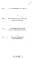
FIG. 2 illustrates a brake system testing method in accordance with various embodiments; and -
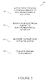
FIG. 3 illustrates a further brake system testing method in accordance with various embodiments. - The detailed description of exemplary embodiments herein makes reference to the accompanying drawings, which show exemplary embodiments by way of illustration. While these exemplary embodiments are described in sufficient detail to enable those skilled in the art to practice the inventions, it should be understood that other embodiments may be realized and that logical changes and adaptations in design and construction may be made in accordance with this invention and the teachings herein. Thus, the detailed description herein is presented for purposes of illustration only and not of limitation. The scope of the invention is defined by the appended claims. For example, the steps recited in any of the method or process descriptions may be executed in any order and are not necessarily limited to the order presented. Furthermore, any reference to singular includes plural embodiments, and any reference to more than one component or step may include a singular embodiment or step. Also, any reference to attached, fixed, connected or the like may include permanent, removable, temporary, partial, full and/or any other possible attachment option. Additionally, any reference to without contact (or similar phrases) may also include reduced contact or minimal contact.
- Furthermore, any reference to singular includes plural embodiments, and any reference to more than one component or step may include a singular embodiment or step. Surface shading lines may be used throughout the figures to denote different parts but not necessarily to denote the same or different materials.
- Although electrical energy is referenced throughout the disclosure and exemplary embodiments, electrical energy is just one exemplary type of electrical parameter such as voltage, current, power, etc. that represents measurable electrical values or phenomena that characterize the behavior of electronic circuits, components, or semiconductors. Any electrical parameter may be substituted in place of electrical energy as would be understood by one of ordinary skill in the applicable art.
- With reference to
Figure 1 , a portion of a wheel andbrake system 10 is illustrated. Wheel andbrake system 10 may comprise, for example, a brake assembly 11. In various embodiments, brake assembly 11 may be coupled to anaxle 15 of awheel 12. For example, brake assembly 11 may exert force against one or more components ofwheel 12 to reduce the speed of an aircraft. - In various embodiments, brake assembly 11 may comprise a
brake stack 27. For example,brake stack 27 may comprise components that interface with bothwheel 12 and brake assembly 11. Further, in various embodiments,brake stack 27 may be configured such that when force is applied,brake stack 27 acts to apply force towheel 12 and reduce the speed of the aircraft. - Brake assembly 11 may further comprise, for example, one or
more brake actuators 36. For example,brake actuators 36 may be configured such that in response to an operator activating a control (e.g., depresses a brake pedal),brake actuators 36 laterally compressbrake stack 27 which, in turn, resist rotation ofwheel 12 and thus reduces the speed of the aircraft. -
Brake actuator 36 may comprise, for example, an electromechanical brake actuator. In various embodiments, a predetermined level of electrical energy may be applied to an electromechanical actuator such asbrake actuator 36, resulting in a predetermined actuation level. In other embodiments,brake actuator 36 may comprise a hydraulic actuator.Hydraulic actuator 36 may, for example, be actuated by applying hydraulic presser tobrake actuator 36. In further embodiments,brake actuator 36 may comprise a hybrid electromechanical-hydraulic actuator. Any type of actuator is within the scope of the present invention. - In various embodiments,
brake actuator 36 may comprise aram 35. For example, actuation ofbrake actuator 36, which may causeram 35 to change position and extend laterally. In various embodiments,ram 35 may extend towards and apply force tobrake stack 27, compressing the stack and reducing the speed of the aircraft. -
Brake actuator 36 may comprise, for example, anelectric motor 50. In various embodiments,electric motor 50 is coupled toram 35 such that applying electrical energy to the motor causesram 35 to extend towards and apply force tobrake stack 27. For example, rotation fromelectric motor 50 may be translated toram 35 by gearing, including various ball screws and/or screw gears. Any manner of translating rotation fromelectric motor 50 to linear motion ofram 35 is within the scope of the present disclosure. For example, ahydraulic brake actuator 36 may convert hydraulic pressure applied to the actuator to linear or angular force toram 35. - In various embodiments, in response actuation being discontinued to brake
actuator 36,ram 35 may be retracted linearly away frombrake stack 27. For example,brake stack 27 may comprise a configuration that exerts a restorative force againstram 35, such thatram 35 is pushed back and away frombrake stack 27 when actuation is discontinued. In various embodiments, discontinuing actuation may comprise discontinuing the application of electrical energy, hydraulic pressure, or any combination of both tobrake actuator 36. - Components of
brake actuator 36 may fail such thatbrake stack 27 is at least partially engaged when no electrical energy is being applied tobrake actuator 36. For example, after electrical energy is applied and discontinued,ram 35 may remain in an extended position. Stated another way,ram 35 may "stick" such that it continues to provide force tobrake stack 27 after electrical energy is discontinued. This scenario may cause unwanted and/or uncommanded braking. - With reference to
Figure 2 , a brakesystem test method 200 is illustrated. In various embodiments, brakesystem test method 200 may be employed to determine if one ormore brake actuators 36 are operating within predetermined operating parameters and therefore are less likely to cause undesired braking. For example, brakesystem test method 200 may be applied to an aircraft that is in flight, in an effort to detect the potential failure of one ormore brake actuators 36 before landing. In other embodiments,test method 200 may be applied to the aircraft during taxiing, parking, or any other phase of operation of the aircraft. - In various embodiments, brake
system test method 200 may be applied to eachbrake actuator 36 of brake assembly 11 individually. In further embodiments, brakesystem test method 200 may be applied to more than one, including, for example, all of thebrake actuators 36 of a given brake assembly 11, at the same time. For example, brake assembly 11 may comprise more than one, such as, for example, fourbrake actuators 36. However, the use of any number of brake actuators is within the scope of the present disclosure. - In various embodiments, brake
system test method 200 comprises at least partially actuating brake actuator instep 202. For example, step 202 may comprise applying electrical energy to apredetermined brake actuator 36 andelectric motor 50 to causeram 35 to extend towards and apply force to brakestack 27. In various embodiments, a predetermined electrical energy level may be applied tobrake actuator 36 that will result in a predetermined force applied byram 35 againstbrake stack 27. Further, the predetermined electrical energy level may be applied for a predetermined time period. - Brake
system test method 200 may further comprise, for example, discontinuing actuation to the electromechanical actuator instep 204. In various embodiments, after a predetermined time period, the predetermined electrical energy level applied to brakeactuator 36 is discontinued. - In various embodiments, brake
system test method 200 comprises determining the actuation level of the brake actuator instep 206. Actuation level may be expressed as the position ofram 35. For example, step 206 may comprise determining the position ofram 35 after discontinuing actuation ofbrake actuator 36. In various embodiments, the position ofram 35 may be determined by a position sensor withinbrake actuator 36. However, any manner of determining the actuation level ofbrake actuator 36 is within the scope of the disclosure. In various embodiments, ram 35 may be extended between about 1 and 20 millimeters, or between about 2 and 10 millimeters, or further, between about 4 and 6 millimeters. - Brake
system test method 200 may further comprise, for example, evaluating braking performance instep 208. In various embodiments,step 208 comprises comparing the position ofram 35 after discontinuing actuation to a predetermined or expected position. If the position ofram 35 is, for example, further extended frombrake actuator 36 than desired, a braking system performance issue may be present. For example, as previously discussed, ifram 35 does not retract to a predetermined position frombrake stack 27 after electrical energy is discontinued, brake assembly 11 may experience undesired and/or uncommanded braking. For example, a difference between the predetermined value and the actuation level between about 1 and 10 millimeters may indicate a braking performance issue. - With reference to
Figure 3 , a brakesystem test method 300 is illustrated. In various embodiments, similarly tomethod 200, brakesystem test method 300 may be employed to determine if one ormore brake actuators 36 are operating within desired operating parameters and therefore are less likely to cause undesired braking. For example, brakesystem test method 300 may be applied to an aircraft that is in flight, taxi, park, or on ground in an effort to detect the potential failure of one or moreelectromechanical actuators 36 before landing. - In various embodiments, brake
system test method 300 comprises an applying a predetermined electrical energy level to anelectromechanical actuator step 302. Similarly to step 202 ofmethod 200,step 302 may comprise applying electrical energy to a desiredelectromechanical actuator 36 to causeram 35 to extend towards and apply force to brakestack 27. In various embodiments, a predetermined electrical energy level may be applied toactuator 36 andelectric motor 50 that will result in a predetermined force applied byram 35 againstbrake stack 27. Further, the predetermined electrical energy level may be applied for a predetermined time period. - Brake
system test method 300 may further comprise, for example, discontinuing electrical energy to theelectromechanical actuator step 304. In various embodiments,step 304 comprises discontinuing the predetermined electrical energy level applied toelectromechanical actuator 36 after a predetermined period of time. - In various embodiments, brake
system test method 300 comprises a measuring voltage from a motor of theelectromechanical actuator step 306. For example, ifram 35 remains engaged with and extended towardsbrake stack 27 after electrical energy is discontinued,electric motor 50 may operate in reverse, generating electrical energy. In various embodiments,step 306 may comprise measuring the electrical voltage produced byelectric motor 50 after discontinuing electrical energy to the ram. In other embodiments,step 306 comprises measuring other electrical characteristics ofelectric motor 50, including, for example, peak power or energy, RMS power or energy, current, or any other electrical characteristic ofmotor 50. - Brake
system test method 300 may further comprise, for example, an evaluating braking performance instep 308. In various embodiments,step 308 comprises comparing the electrical voltage produced byelectric motor 50 ofelectromechanical actuator 36 after discontinuing electrical energy to a predicted or expected position. If the voltage generated byelectric motor 50 is, for example, less than an expected value, a braking system performance issue may be present. For example, as previously discussed, ifram 35 does not retract frombrake stack 27 after electrical energy is discontinued, brake assembly 11 may experience undesired and/or uncommanded braking. A lower than anticipated voltage produced byelectric motor 50 may indicate such undesired and/or uncommanded braking. For example, a difference between an anticipated voltage produced byelectric motor 50 and the measured voltage generated by theelectric motor 50 may be between about 1 and 1000 volts, or between about 100 and 900 volts, or further, between about 200 and 700 volts. - Benefits, other advantages, and solutions to problems have been described herein with regard to specific embodiments. Furthermore, the connecting lines shown in the various figures contained herein are intended to represent exemplary functional relationships and/or physical couplings between the various elements. It should be noted that many alternative or additional functional relationships or physical connections may be present in a practical system. However, the benefits, advantages, solutions to problems, and any elements that may cause any benefit, advantage, or solution to occur or become more pronounced are not to be construed as critical, required, or essential features or elements of the disclosure. The scope of the disclosure is accordingly to be limited by nothing other than the appended claims, in which reference to an element in the singular is not intended to mean "one and only one" unless explicitly so stated, but rather "one or more." Moreover, where a phrase similar to "at least one of A, B, or C" is used in the claims, it is intended that the phrase be interpreted to mean that A alone may be present in an embodiment, B alone may be present in an embodiment, C alone may be present in an embodiment, or that any combination of the elements A, B and C may be present in a single embodiment; for example, A and B, A and C, B and C, or A and B and C. Different cross-hatching is used throughout the figures to denote different parts but not necessarily to denote the same or different materials.
- Systems, methods and apparatus are provided herein. In the detailed description herein, references to "one embodiment", "an embodiment", "various embodiments", etc., indicate that the embodiment described may include a particular feature, structure, or characteristic, but every embodiment may not necessarily include the particular feature, structure, or characteristic. Moreover, such phrases are not necessarily referring to the same embodiment. Further, when a particular feature, structure, or characteristic is described in connection with an embodiment, it is submitted that it is within the knowledge of one skilled in the art to affect such feature, structure, or characteristic in connection with other embodiments whether or not explicitly described. After reading the description, it will be apparent to one skilled in the relevant art(s) how to implement the disclosure in alternative embodiments.
Claims (15)
- A method for testing the operation of an aircraft braking system comprising:at least partially actuating a brake actuator attached to a brake assembly, wherein the brake assembly comprises a brake stack;discontinuing actuating the electromechanical actuator;determining an actuation level of the electromechanical actuator; andevaluating braking performance.
- The testing method of claim 1, wherein the actuator is an electromechanical actuator.
- The testing method of claim 2, wherein the braking system comprises four electromechanical actuators.
- The testing method of claim 1, wherein the determining the actuation level of the actuator comprises receiving a signal from a position detector of the actuator.
- The testing method of claim 1, wherein the evaluating the braking performance comprises comparing the actuation level of the actuator to a predetermined value.
- The testing method of claim 5, wherein difference between the predetermined value and the actuation level is between about 1 and 20 millimeters.
- The testing method of claim 1, wherein the testing method is performed on an aircraft as it is in flight.
- A method for testing the operation of an aircraft braking system comprising:applying a predetermined electrical energy level to an electromechanical actuator attached to a brake assembly, wherein the brake assembly comprises a brake stack;discontinuing electrical energy to the electromechanical actuator;measuring a voltage from a motor of the electromechanical actuator; andevaluating braking performance.
- The testing method of claim 8, wherein the braking system comprises four electromechanical actuators.
- The testing method of claim 9, wherein each of the electromechanical actuators are tested independently from one another.
- The testing method of claim 9, wherein two or more of the electromechanical actuator are tested simultaneously.
- The testing method of claim 8, wherein the measuring the voltage from the motor of the electromechanical actuator comprises receiving a voltage signal from the motor of the electromechanical actuator operating as a generator.
- The testing method of claim 11, wherein the evaluating the braking performance comprises comparing the voltage produced by the motor of the electromechanical actuator to a predetermined value.
- The testing method of claim 12, wherein the difference between the voltage produced by the motor and the predetermined value is between about 100 volts and 600 volts.
- The testing method of claim 8, wherein the testing method is performed on an aircraft as it is taxiing or parked.
Applications Claiming Priority (1)
| Application Number | Priority Date | Filing Date | Title |
|---|---|---|---|
| US14/290,521 US9227617B2 (en) | 2014-05-29 | 2014-05-29 | Aircraft brake system testing methods |
Publications (2)
| Publication Number | Publication Date |
|---|---|
| EP2949524A1 true EP2949524A1 (en) | 2015-12-02 |
| EP2949524B1 EP2949524B1 (en) | 2019-12-11 |
Family
ID=53191499
Family Applications (1)
| Application Number | Title | Priority Date | Filing Date |
|---|---|---|---|
| EP15168145.9A Active EP2949524B1 (en) | 2014-05-29 | 2015-05-19 | Aircraft brake system testing methods |
Country Status (2)
| Country | Link |
|---|---|
| US (2) | US9227617B2 (en) |
| EP (1) | EP2949524B1 (en) |
Cited By (1)
| Publication number | Priority date | Publication date | Assignee | Title |
|---|---|---|---|---|
| EP3666648A1 (en) * | 2018-12-14 | 2020-06-17 | Goodrich Corporation | Performing brake testing in flight on approach with bcs |
Families Citing this family (4)
| Publication number | Priority date | Publication date | Assignee | Title |
|---|---|---|---|---|
| US10807576B2 (en) * | 2016-11-09 | 2020-10-20 | Allison Transmission, Inc. | Brake actuator-based prognostic system and method thereof |
| FR3094313B1 (en) * | 2019-04-01 | 2024-05-31 | Safran Landing Systems | Braking system of an aircraft wheel, configurable according to a normal mode or according to an RTO mode |
| GB2588598A (en) | 2019-10-21 | 2021-05-05 | Airbus Operations Ltd | Aircraft system |
| US12194974B2 (en) * | 2020-08-20 | 2025-01-14 | Goodrich Corporation | Systems and methods for pressure control mixed mode for braking operation |
Citations (6)
| Publication number | Priority date | Publication date | Assignee | Title |
|---|---|---|---|---|
| US20050082999A1 (en) * | 2003-10-15 | 2005-04-21 | Russ Ether | Electro-mechanical actuator braking apparatus and method using motor commutation sensor output to derive piston displacement |
| US20060108867A1 (en) * | 2004-09-17 | 2006-05-25 | Mihai Ralea | Electromechanical braking system with electrical energy back-up and regenerative energy management |
| GB2470099A (en) * | 2009-05-05 | 2010-11-10 | Goodrich Corp | Brake testing mode that uses a simulated wheel speed data |
| GB2470251A (en) * | 2009-05-14 | 2010-11-17 | Goodrich Corp | Testing a brake disc stack |
| EP2565093A1 (en) * | 2011-09-02 | 2013-03-06 | Goodrich Corporation | Systems and methods for braking system testing |
| EP2719596A1 (en) * | 2012-10-12 | 2014-04-16 | Goodrich Corporation | System and method of determining a status of a brake assembly |
Family Cites Families (2)
| Publication number | Priority date | Publication date | Assignee | Title |
|---|---|---|---|---|
| EP1954538B1 (en) * | 2005-11-30 | 2014-05-21 | Goodrich Corporation | Controller for electromechanical braking system with running clearance adjustment and method |
| US9211878B2 (en) * | 2013-03-06 | 2015-12-15 | Hamilton Sundstrand Corporation | In situ flap and slat wing tip brake response tester |
-
2014
- 2014-05-29 US US14/290,521 patent/US9227617B2/en active Active
-
2015
- 2015-05-19 EP EP15168145.9A patent/EP2949524B1/en active Active
- 2015-10-30 US US14/929,031 patent/US9714019B2/en active Active
Patent Citations (6)
| Publication number | Priority date | Publication date | Assignee | Title |
|---|---|---|---|---|
| US20050082999A1 (en) * | 2003-10-15 | 2005-04-21 | Russ Ether | Electro-mechanical actuator braking apparatus and method using motor commutation sensor output to derive piston displacement |
| US20060108867A1 (en) * | 2004-09-17 | 2006-05-25 | Mihai Ralea | Electromechanical braking system with electrical energy back-up and regenerative energy management |
| GB2470099A (en) * | 2009-05-05 | 2010-11-10 | Goodrich Corp | Brake testing mode that uses a simulated wheel speed data |
| GB2470251A (en) * | 2009-05-14 | 2010-11-17 | Goodrich Corp | Testing a brake disc stack |
| EP2565093A1 (en) * | 2011-09-02 | 2013-03-06 | Goodrich Corporation | Systems and methods for braking system testing |
| EP2719596A1 (en) * | 2012-10-12 | 2014-04-16 | Goodrich Corporation | System and method of determining a status of a brake assembly |
Cited By (2)
| Publication number | Priority date | Publication date | Assignee | Title |
|---|---|---|---|---|
| EP3666648A1 (en) * | 2018-12-14 | 2020-06-17 | Goodrich Corporation | Performing brake testing in flight on approach with bcs |
| US10807585B2 (en) | 2018-12-14 | 2020-10-20 | Goodrich Corporation | Performing brake testing in flight on approach with a brake control system |
Also Published As
| Publication number | Publication date |
|---|---|
| US9227617B2 (en) | 2016-01-05 |
| US9714019B2 (en) | 2017-07-25 |
| EP2949524B1 (en) | 2019-12-11 |
| US20160052502A1 (en) | 2016-02-25 |
| US20150344017A1 (en) | 2015-12-03 |
Similar Documents
| Publication | Publication Date | Title |
|---|---|---|
| US9714019B2 (en) | Aircraft brake system testing methods | |
| US10882500B2 (en) | Systems and methods for brake failure detection using retract braking | |
| EP2613988B1 (en) | Failure detection method in a vehicle brake, control unit to perform the method and parking brake with such a control unit | |
| EP2871104B1 (en) | System for independent braking system enablement | |
| US20100292889A1 (en) | Brake operation built-in test equipment | |
| US10259569B2 (en) | Systems and methods for emergency aircraft brake operation | |
| US9715770B2 (en) | Systems and methods for built in test equipment for a brake control system | |
| EP3333069A1 (en) | Systems and methods for aircraft emergency and park brakes | |
| DE102016208613A1 (en) | Brake device for a motor vehicle and method for detecting damage to the brake device | |
| US10807585B2 (en) | Performing brake testing in flight on approach with a brake control system | |
| EP3434542B1 (en) | Failsafe synthetic angle generation algorithm for aircraft electric braking system | |
| US20180266850A1 (en) | Displacement sensor | |
| US10882498B2 (en) | Electrical power connection in an emergency park brake system | |
| CN107672579A (en) | Method for carrying out functional check to the brake apparatus of electromechanics | |
| US9776612B2 (en) | Method for checking an automatic parking brake system | |
| EP3392140A1 (en) | Emergency park brake system | |
| DE102004013868B4 (en) | Pedal device for actuating a brake system of a motor vehicle and corresponding method for checking a pedal force sensor | |
| US20190016326A1 (en) | Brake handle for emergency electric braking | |
| EP3029827A2 (en) | Method of detecting an electric actuator with decreased efficiency | |
| US9037371B2 (en) | Systems and methods for manual braking system | |
| US20250162562A1 (en) | Control for an electromechanical brake actuator | |
| DE102011081341B4 (en) | Parking brake in a vehicle | |
| DE102018220583A1 (en) | Checking unit for an actuating device of an electrical device | |
| DE102011006623A1 (en) | Method for determining characteristic curve of parking brake by control device of driver assistance system of vehicle, involves determining pressure-volume characteristic curve of brake piston based on force-displacement characteristic |
Legal Events
| Date | Code | Title | Description |
|---|---|---|---|
| AK | Designated contracting states |
Kind code of ref document: A1 Designated state(s): AL AT BE BG CH CY CZ DE DK EE ES FI FR GB GR HR HU IE IS IT LI LT LU LV MC MK MT NL NO PL PT RO RS SE SI SK SM TR |
|
| AX | Request for extension of the european patent |
Extension state: BA ME |
|
| PUAI | Public reference made under article 153(3) epc to a published international application that has entered the european phase |
Free format text: ORIGINAL CODE: 0009012 |
|
| 17P | Request for examination filed |
Effective date: 20160602 |
|
| RBV | Designated contracting states (corrected) |
Designated state(s): AL AT BE BG CH CY CZ DE DK EE ES FI FR GB GR HR HU IE IS IT LI LT LU LV MC MK MT NL NO PL PT RO RS SE SI SK SM TR |
|
| STAA | Information on the status of an ep patent application or granted ep patent |
Free format text: STATUS: EXAMINATION IS IN PROGRESS |
|
| 17Q | First examination report despatched |
Effective date: 20180523 |
|
| GRAP | Despatch of communication of intention to grant a patent |
Free format text: ORIGINAL CODE: EPIDOSNIGR1 |
|
| STAA | Information on the status of an ep patent application or granted ep patent |
Free format text: STATUS: GRANT OF PATENT IS INTENDED |
|
| INTG | Intention to grant announced |
Effective date: 20190628 |
|
| RIN1 | Information on inventor provided before grant (corrected) |
Inventor name: CAHILL, ERIC Inventor name: GEORGIN, MARC |
|
| GRAS | Grant fee paid |
Free format text: ORIGINAL CODE: EPIDOSNIGR3 |
|
| GRAA | (expected) grant |
Free format text: ORIGINAL CODE: 0009210 |
|
| STAA | Information on the status of an ep patent application or granted ep patent |
Free format text: STATUS: THE PATENT HAS BEEN GRANTED |
|
| AK | Designated contracting states |
Kind code of ref document: B1 Designated state(s): AL AT BE BG CH CY CZ DE DK EE ES FI FR GB GR HR HU IE IS IT LI LT LU LV MC MK MT NL NO PL PT RO RS SE SI SK SM TR |
|
| REG | Reference to a national code |
Ref country code: GB Ref legal event code: FG4D |
|
| REG | Reference to a national code |
Ref country code: CH Ref legal event code: EP |
|
| REG | Reference to a national code |
Ref country code: AT Ref legal event code: REF Ref document number: 1211894 Country of ref document: AT Kind code of ref document: T Effective date: 20191215 |
|
| REG | Reference to a national code |
Ref country code: DE Ref legal event code: R096 Ref document number: 602015043324 Country of ref document: DE |
|
| REG | Reference to a national code |
Ref country code: IE Ref legal event code: FG4D |
|
| REG | Reference to a national code |
Ref country code: NL Ref legal event code: MP Effective date: 20191211 |
|
| REG | Reference to a national code |
Ref country code: LT Ref legal event code: MG4D |
|
| PG25 | Lapsed in a contracting state [announced via postgrant information from national office to epo] |
Ref country code: FI Free format text: LAPSE BECAUSE OF FAILURE TO SUBMIT A TRANSLATION OF THE DESCRIPTION OR TO PAY THE FEE WITHIN THE PRESCRIBED TIME-LIMIT Effective date: 20191211 Ref country code: SE Free format text: LAPSE BECAUSE OF FAILURE TO SUBMIT A TRANSLATION OF THE DESCRIPTION OR TO PAY THE FEE WITHIN THE PRESCRIBED TIME-LIMIT Effective date: 20191211 Ref country code: LT Free format text: LAPSE BECAUSE OF FAILURE TO SUBMIT A TRANSLATION OF THE DESCRIPTION OR TO PAY THE FEE WITHIN THE PRESCRIBED TIME-LIMIT Effective date: 20191211 Ref country code: BG Free format text: LAPSE BECAUSE OF FAILURE TO SUBMIT A TRANSLATION OF THE DESCRIPTION OR TO PAY THE FEE WITHIN THE PRESCRIBED TIME-LIMIT Effective date: 20200311 Ref country code: GR Free format text: LAPSE BECAUSE OF FAILURE TO SUBMIT A TRANSLATION OF THE DESCRIPTION OR TO PAY THE FEE WITHIN THE PRESCRIBED TIME-LIMIT Effective date: 20200312 Ref country code: LV Free format text: LAPSE BECAUSE OF FAILURE TO SUBMIT A TRANSLATION OF THE DESCRIPTION OR TO PAY THE FEE WITHIN THE PRESCRIBED TIME-LIMIT Effective date: 20191211 Ref country code: NO Free format text: LAPSE BECAUSE OF FAILURE TO SUBMIT A TRANSLATION OF THE DESCRIPTION OR TO PAY THE FEE WITHIN THE PRESCRIBED TIME-LIMIT Effective date: 20200311 |
|
| PG25 | Lapsed in a contracting state [announced via postgrant information from national office to epo] |
Ref country code: RS Free format text: LAPSE BECAUSE OF FAILURE TO SUBMIT A TRANSLATION OF THE DESCRIPTION OR TO PAY THE FEE WITHIN THE PRESCRIBED TIME-LIMIT Effective date: 20191211 Ref country code: HR Free format text: LAPSE BECAUSE OF FAILURE TO SUBMIT A TRANSLATION OF THE DESCRIPTION OR TO PAY THE FEE WITHIN THE PRESCRIBED TIME-LIMIT Effective date: 20191211 |
|
| PG25 | Lapsed in a contracting state [announced via postgrant information from national office to epo] |
Ref country code: AL Free format text: LAPSE BECAUSE OF FAILURE TO SUBMIT A TRANSLATION OF THE DESCRIPTION OR TO PAY THE FEE WITHIN THE PRESCRIBED TIME-LIMIT Effective date: 20191211 |
|
| PG25 | Lapsed in a contracting state [announced via postgrant information from national office to epo] |
Ref country code: EE Free format text: LAPSE BECAUSE OF FAILURE TO SUBMIT A TRANSLATION OF THE DESCRIPTION OR TO PAY THE FEE WITHIN THE PRESCRIBED TIME-LIMIT Effective date: 20191211 Ref country code: PT Free format text: LAPSE BECAUSE OF FAILURE TO SUBMIT A TRANSLATION OF THE DESCRIPTION OR TO PAY THE FEE WITHIN THE PRESCRIBED TIME-LIMIT Effective date: 20200506 Ref country code: NL Free format text: LAPSE BECAUSE OF FAILURE TO SUBMIT A TRANSLATION OF THE DESCRIPTION OR TO PAY THE FEE WITHIN THE PRESCRIBED TIME-LIMIT Effective date: 20191211 Ref country code: ES Free format text: LAPSE BECAUSE OF FAILURE TO SUBMIT A TRANSLATION OF THE DESCRIPTION OR TO PAY THE FEE WITHIN THE PRESCRIBED TIME-LIMIT Effective date: 20191211 Ref country code: CZ Free format text: LAPSE BECAUSE OF FAILURE TO SUBMIT A TRANSLATION OF THE DESCRIPTION OR TO PAY THE FEE WITHIN THE PRESCRIBED TIME-LIMIT Effective date: 20191211 Ref country code: RO Free format text: LAPSE BECAUSE OF FAILURE TO SUBMIT A TRANSLATION OF THE DESCRIPTION OR TO PAY THE FEE WITHIN THE PRESCRIBED TIME-LIMIT Effective date: 20191211 |
|
| PG25 | Lapsed in a contracting state [announced via postgrant information from national office to epo] |
Ref country code: IS Free format text: LAPSE BECAUSE OF FAILURE TO SUBMIT A TRANSLATION OF THE DESCRIPTION OR TO PAY THE FEE WITHIN THE PRESCRIBED TIME-LIMIT Effective date: 20200411 Ref country code: SK Free format text: LAPSE BECAUSE OF FAILURE TO SUBMIT A TRANSLATION OF THE DESCRIPTION OR TO PAY THE FEE WITHIN THE PRESCRIBED TIME-LIMIT Effective date: 20191211 Ref country code: SM Free format text: LAPSE BECAUSE OF FAILURE TO SUBMIT A TRANSLATION OF THE DESCRIPTION OR TO PAY THE FEE WITHIN THE PRESCRIBED TIME-LIMIT Effective date: 20191211 |
|
| REG | Reference to a national code |
Ref country code: DE Ref legal event code: R097 Ref document number: 602015043324 Country of ref document: DE |
|
| REG | Reference to a national code |
Ref country code: AT Ref legal event code: MK05 Ref document number: 1211894 Country of ref document: AT Kind code of ref document: T Effective date: 20191211 |
|
| PLBE | No opposition filed within time limit |
Free format text: ORIGINAL CODE: 0009261 |
|
| STAA | Information on the status of an ep patent application or granted ep patent |
Free format text: STATUS: NO OPPOSITION FILED WITHIN TIME LIMIT |
|
| PG25 | Lapsed in a contracting state [announced via postgrant information from national office to epo] |
Ref country code: DK Free format text: LAPSE BECAUSE OF FAILURE TO SUBMIT A TRANSLATION OF THE DESCRIPTION OR TO PAY THE FEE WITHIN THE PRESCRIBED TIME-LIMIT Effective date: 20191211 |
|
| 26N | No opposition filed |
Effective date: 20200914 |
|
| PG25 | Lapsed in a contracting state [announced via postgrant information from national office to epo] |
Ref country code: SI Free format text: LAPSE BECAUSE OF FAILURE TO SUBMIT A TRANSLATION OF THE DESCRIPTION OR TO PAY THE FEE WITHIN THE PRESCRIBED TIME-LIMIT Effective date: 20191211 Ref country code: AT Free format text: LAPSE BECAUSE OF FAILURE TO SUBMIT A TRANSLATION OF THE DESCRIPTION OR TO PAY THE FEE WITHIN THE PRESCRIBED TIME-LIMIT Effective date: 20191211 |
|
| REG | Reference to a national code |
Ref country code: DE Ref legal event code: R119 Ref document number: 602015043324 Country of ref document: DE |
|
| PG25 | Lapsed in a contracting state [announced via postgrant information from national office to epo] |
Ref country code: MC Free format text: LAPSE BECAUSE OF FAILURE TO SUBMIT A TRANSLATION OF THE DESCRIPTION OR TO PAY THE FEE WITHIN THE PRESCRIBED TIME-LIMIT Effective date: 20191211 Ref country code: CH Free format text: LAPSE BECAUSE OF NON-PAYMENT OF DUE FEES Effective date: 20200531 Ref country code: IT Free format text: LAPSE BECAUSE OF FAILURE TO SUBMIT A TRANSLATION OF THE DESCRIPTION OR TO PAY THE FEE WITHIN THE PRESCRIBED TIME-LIMIT Effective date: 20191211 Ref country code: LI Free format text: LAPSE BECAUSE OF NON-PAYMENT OF DUE FEES Effective date: 20200531 |
|
| PG25 | Lapsed in a contracting state [announced via postgrant information from national office to epo] |
Ref country code: PL Free format text: LAPSE BECAUSE OF FAILURE TO SUBMIT A TRANSLATION OF THE DESCRIPTION OR TO PAY THE FEE WITHIN THE PRESCRIBED TIME-LIMIT Effective date: 20191211 |
|
| REG | Reference to a national code |
Ref country code: BE Ref legal event code: MM Effective date: 20200531 |
|
| PG25 | Lapsed in a contracting state [announced via postgrant information from national office to epo] |
Ref country code: LU Free format text: LAPSE BECAUSE OF NON-PAYMENT OF DUE FEES Effective date: 20200519 |
|
| PG25 | Lapsed in a contracting state [announced via postgrant information from national office to epo] |
Ref country code: IE Free format text: LAPSE BECAUSE OF NON-PAYMENT OF DUE FEES Effective date: 20200519 |
|
| PG25 | Lapsed in a contracting state [announced via postgrant information from national office to epo] |
Ref country code: BE Free format text: LAPSE BECAUSE OF NON-PAYMENT OF DUE FEES Effective date: 20200531 Ref country code: DE Free format text: LAPSE BECAUSE OF NON-PAYMENT OF DUE FEES Effective date: 20201201 |
|
| PG25 | Lapsed in a contracting state [announced via postgrant information from national office to epo] |
Ref country code: TR Free format text: LAPSE BECAUSE OF FAILURE TO SUBMIT A TRANSLATION OF THE DESCRIPTION OR TO PAY THE FEE WITHIN THE PRESCRIBED TIME-LIMIT Effective date: 20191211 Ref country code: MT Free format text: LAPSE BECAUSE OF FAILURE TO SUBMIT A TRANSLATION OF THE DESCRIPTION OR TO PAY THE FEE WITHIN THE PRESCRIBED TIME-LIMIT Effective date: 20191211 Ref country code: CY Free format text: LAPSE BECAUSE OF FAILURE TO SUBMIT A TRANSLATION OF THE DESCRIPTION OR TO PAY THE FEE WITHIN THE PRESCRIBED TIME-LIMIT Effective date: 20191211 |
|
| PG25 | Lapsed in a contracting state [announced via postgrant information from national office to epo] |
Ref country code: MK Free format text: LAPSE BECAUSE OF FAILURE TO SUBMIT A TRANSLATION OF THE DESCRIPTION OR TO PAY THE FEE WITHIN THE PRESCRIBED TIME-LIMIT Effective date: 20191211 |
|
| P01 | Opt-out of the competence of the unified patent court (upc) registered |
Effective date: 20230522 |
|
| PGFP | Annual fee paid to national office [announced via postgrant information from national office to epo] |
Ref country code: GB Payment date: 20250423 Year of fee payment: 11 |
|
| PGFP | Annual fee paid to national office [announced via postgrant information from national office to epo] |
Ref country code: FR Payment date: 20250423 Year of fee payment: 11 |