EP2949518A1 - Motor-vehicle front structure with an improved front-end unit - Google Patents
Motor-vehicle front structure with an improved front-end unit Download PDFInfo
- Publication number
- EP2949518A1 EP2949518A1 EP15159925.5A EP15159925A EP2949518A1 EP 2949518 A1 EP2949518 A1 EP 2949518A1 EP 15159925 A EP15159925 A EP 15159925A EP 2949518 A1 EP2949518 A1 EP 2949518A1
- Authority
- EP
- European Patent Office
- Prior art keywords
- cross
- plates
- crash
- end unit
- box
- Prior art date
- Legal status (The legal status is an assumption and is not a legal conclusion. Google has not performed a legal analysis and makes no representation as to the accuracy of the status listed.)
- Granted
Links
Images


Classifications
-
- B—PERFORMING OPERATIONS; TRANSPORTING
- B60—VEHICLES IN GENERAL
- B60R—VEHICLES, VEHICLE FITTINGS, OR VEHICLE PARTS, NOT OTHERWISE PROVIDED FOR
- B60R19/00—Wheel guards; Radiator guards, e.g. grilles; Obstruction removers; Fittings damping bouncing force in collisions
- B60R19/02—Bumpers, i.e. impact receiving or absorbing members for protecting vehicles or fending off blows from other vehicles or objects
- B60R19/24—Arrangements for mounting bumpers on vehicles
- B60R19/26—Arrangements for mounting bumpers on vehicles comprising yieldable mounting means
- B60R19/34—Arrangements for mounting bumpers on vehicles comprising yieldable mounting means destroyed upon impact, e.g. one-shot type
-
- B—PERFORMING OPERATIONS; TRANSPORTING
- B60—VEHICLES IN GENERAL
- B60R—VEHICLES, VEHICLE FITTINGS, OR VEHICLE PARTS, NOT OTHERWISE PROVIDED FOR
- B60R19/00—Wheel guards; Radiator guards, e.g. grilles; Obstruction removers; Fittings damping bouncing force in collisions
- B60R19/02—Bumpers, i.e. impact receiving or absorbing members for protecting vehicles or fending off blows from other vehicles or objects
- B60R19/023—Details
-
- B—PERFORMING OPERATIONS; TRANSPORTING
- B60—VEHICLES IN GENERAL
- B60R—VEHICLES, VEHICLE FITTINGS, OR VEHICLE PARTS, NOT OTHERWISE PROVIDED FOR
- B60R19/00—Wheel guards; Radiator guards, e.g. grilles; Obstruction removers; Fittings damping bouncing force in collisions
- B60R19/02—Bumpers, i.e. impact receiving or absorbing members for protecting vehicles or fending off blows from other vehicles or objects
- B60R19/03—Bumpers, i.e. impact receiving or absorbing members for protecting vehicles or fending off blows from other vehicles or objects characterised by material, e.g. composite
-
- B—PERFORMING OPERATIONS; TRANSPORTING
- B60—VEHICLES IN GENERAL
- B60R—VEHICLES, VEHICLE FITTINGS, OR VEHICLE PARTS, NOT OTHERWISE PROVIDED FOR
- B60R19/00—Wheel guards; Radiator guards, e.g. grilles; Obstruction removers; Fittings damping bouncing force in collisions
- B60R19/02—Bumpers, i.e. impact receiving or absorbing members for protecting vehicles or fending off blows from other vehicles or objects
- B60R19/04—Bumpers, i.e. impact receiving or absorbing members for protecting vehicles or fending off blows from other vehicles or objects formed from more than one section in a side-by-side arrangement
- B60R19/12—Bumpers, i.e. impact receiving or absorbing members for protecting vehicles or fending off blows from other vehicles or objects formed from more than one section in a side-by-side arrangement vertically spaced
-
- B—PERFORMING OPERATIONS; TRANSPORTING
- B62—LAND VEHICLES FOR TRAVELLING OTHERWISE THAN ON RAILS
- B62D—MOTOR VEHICLES; TRAILERS
- B62D21/00—Understructures, i.e. chassis frame on which a vehicle body may be mounted
- B62D21/15—Understructures, i.e. chassis frame on which a vehicle body may be mounted having impact absorbing means, e.g. a frame designed to permanently or temporarily change shape or dimension upon impact with another body
- B62D21/152—Front or rear frames
-
- B—PERFORMING OPERATIONS; TRANSPORTING
- B62—LAND VEHICLES FOR TRAVELLING OTHERWISE THAN ON RAILS
- B62D—MOTOR VEHICLES; TRAILERS
- B62D25/00—Superstructure or monocoque structure sub-units; Parts or details thereof not otherwise provided for
- B62D25/08—Front or rear portions
- B62D25/082—Engine compartments
- B62D25/085—Front-end modules
-
- B—PERFORMING OPERATIONS; TRANSPORTING
- B60—VEHICLES IN GENERAL
- B60R—VEHICLES, VEHICLE FITTINGS, OR VEHICLE PARTS, NOT OTHERWISE PROVIDED FOR
- B60R19/00—Wheel guards; Radiator guards, e.g. grilles; Obstruction removers; Fittings damping bouncing force in collisions
- B60R19/02—Bumpers, i.e. impact receiving or absorbing members for protecting vehicles or fending off blows from other vehicles or objects
- B60R19/24—Arrangements for mounting bumpers on vehicles
- B60R2019/242—Arrangements for mounting bumpers on vehicles on two vertical sleeves, e.g. on energy absorber ends
Definitions
- the present invention relates to a motor-vehicle front structure, of the type comprising:
- Document EP 2 301 825 A2 discloses a motor-vehicle front structure of the same type indicated above, in which the front-end unit has no lower cross-member and in which moreover said crash-box plates are connected directly to said strut plates, without the interposition therebetween of elements forming part of the front-end unit.
- a front-end structure is also known from document FR 2 919 567 A1 .
- the object of the present invention is that of providing a motor-vehicle structure of the type indicated at the beginning of the present description which maintains the advantage which are proper of a front-end unit, among which that of using this unit for supporting motor-vehicle auxiliary components (such as the radiator or components of the air conditioning system), as well as that of contributing to accumulate impact energy in the case of low speed impacts and to enable easier assembling and repairing operations on the motor-vehicle, and further having a structure which is simpler and of lower cost and yet provided with suitable characteristics with regard to the structural resistance and the capability of accumulating impact energy.
- the invention provides a motor-vehicle front structure, comprising a pair of longitudinal struts with front-ends to which two strut plates are secured,
- the structure of the front-end unit is greatly simplified and has a simpler and more inexpensive construction, while insuring the required characteristics with regard to structural resistance and ability of accumulating impact energy.
- the crash-box plates which are placed in contact directly with the strut plates have upper portions projecting above the strut plates for forming two connecting brackets for connection to the ends of the upper cross-member of the front-end unit.
- the two crash-box plates are connected to said two supports carrying said lower auxiliary cross-member.
- these supports are constituted by two steel sheets, which are L-shaped, with vertical portions connected to the two crash-box plates and horizontal portions connected to the ends of the lower cross-member of plastic material of the front-end unit.
- the known solution which has been already discussed in the foregoing and developed by the same applicant is of a type in which the motor-vehicle structure comprises, in a way which is per se conventional, two longitudinal beans L on whose front ends there are secured in any known way (such as by welding) two strut plates P1.
- the known structure further comprises a front cross-member T1, made of aluminium and located forwardly of the two strut plates P1.
- the ends of the front cross-member T1 are connected by means of two crash-box structures CB to two crash-box plates P2.
- Both plates P2 and the crash-box structures CB are made of aluminium.
- the crash-box structures CB are configured so as to be adapted to be deformed and thereby accumulating impact energy in the case of low speed impacts.
- the two crash-box plates P2 are further connected to a lower auxiliary cross-member T2, made of steel, by means of two side supports S having a structure of aluminium configured for being able to accumulate impact energy.
- Cross-member T2 is specifically provided for transmitting the impact energy to the two supports S in the case of a low speed front impact against a pedestrian.
- Reference FE generally designates a front-end unit for supporting one or more motor-vehicle auxiliary components (not shown).
- the unit FE is interposed between the front cross-member T1 and the strut plates P1. More specifically, in the case of the known solution shown in figures 1 , 2 , the front-end unit FE has a single structure of plastic material including a front-end upper cross-member M1, a front-end lower cross-member M2, and two uprights U which connect the ends of the upper and lower cross-members M1, M2 to each other. Within the uprights U of plastic material there are embedded two steel plates P3.
- the plates P3 forming part of the structure of the front-end unit are interposed in the connection between the crash-box plates P2 and the strut plates P1.
- This connection is provided by screws V which engage cooperating holes formed in plates P1, P2, P3. Therefore, in the known solution, the crash-box plates P2 are connected to the strut plates P1 with the interposition of plates P3 forming part of the front-end unit.
- connection of the front-end unit to the motor-vehicle structure is completed by a steel bracket B which has one end connected by means of screws to the central part of the upper cross-member M1 of the front-end unit FE and the opposite end connected to a bracket B1 secured to the central part of the front cross-member T1.
- FIG. 3-7 The preferred embodiment of the present invention is shown in figures 3-7 .
- a comparison of figures 3 , 4 with figures 1 , 2 immediately shows the main differences of the invention with respect to the known solution.
- the parts in common to those of figures 1 , 2 are designated by the same reference signs.
- the two crash-box plates P2 are directly connected to the two strut plates P1, without any interposition of elements forming part of the front-end unit therebetween.
- the plates P3 forming part of the front-end unit according to the known solution have been completely eliminated.
- the front-end unit FE comprises an upper cross-member M1 made of plastic material and a lower cross-member M2 made of plastic material which constitute two elements which are separated from each other and both connected to the two crash-box plates P2.
- the upper cross-member M1 of the front-end unit FE has its ends connected directly to the two crash-box plates P2.
- the two crash-box plates P2 which are placed directly in contact with the two strut plates P1 and are screwed thereto by screws V, include upper portions A projecting above the strut plates P1 in the mounted condition and adapted to form two attachment lugs for screwing thereto of the ends of the upper cross-member M1 of plastic material of the front-end unit.
- the lower cross-member M2 of plastic material of the front-end unit FE is connected to the crash-box plates P2 with the interposition of the two supports S, which support the auxiliary cross-member T2.
- the two supports S are constituted by two steel sheets, having an L-shape, with vertical portions S1 screwed to the lower ends of the two crash-box plates P2, and two horizontal portions S2 to which the ends of the lower cross-member M2 of plastic material of the front-end unit FE are screwed.
- the front-end unit according to the embodiment disclosed herein is constituted by two separate components, i.e. the upper cross-member M1 and the lower cross-member M2.
- the central part of the upper cross-member M1 of the front-end unit FE is connected by means of the bracket B to the central part of the front-cross member T1, similarly to the known solution.
Landscapes
- Engineering & Computer Science (AREA)
- Mechanical Engineering (AREA)
- Chemical & Material Sciences (AREA)
- Combustion & Propulsion (AREA)
- Transportation (AREA)
- Body Structure For Vehicles (AREA)
Abstract
Description
- The present invention relates to a motor-vehicle front structure, of the type comprising:
- a pair of longitudinal struts, with front ends to which two strut plates are secured,
- a front cross-member located forwardly of the strut plates and having ends provided with two rearwardly facing cross-member plates, which are rigidly connected to said strut plates,
- wherein each cross-member plate is a crash-box plate, connected to said cross-member with the interposition of a crash-box structure,
- wherein said crash-box plates are further connected to an auxiliary lower cross-member, by means of two respective supports each having an upper end connected to the respective crash-box plate and a lower end connected to a respective end of the auxiliary cross-member,
- a front-end unit for supporting one or more motor-vehicle auxiliary components, said front-end unit being interposed between the front cross-member and the strut plates, and including at least an upper cross-member and a lower cross-member constituted of plastic material.
- In the past the applicant has developed a motor-vehicle having a structure of the above indicated type, wherein said upper and lower cross-members of the front-end unit form part of a single structure of plastic material incorporating two uprights which connect the upper and lower cross-members of the front-unit to each other. In this prior solution, within the uprights of the front-end unit there are embedded two metal plates which are interposed in the connection between the two crush-box plates and the two strut plates.
-
Document EP 2 301 825 A2 , to which the preamble of annexedclaim 1 refers, discloses a motor-vehicle front structure of the same type indicated above, in which the front-end unit has no lower cross-member and in which moreover said crash-box plates are connected directly to said strut plates, without the interposition therebetween of elements forming part of the front-end unit. - A front-end structure is also known from
document FR 2 919 567 A1 - The object of the present invention is that of providing a motor-vehicle structure of the type indicated at the beginning of the present description which maintains the advantage which are proper of a front-end unit, among which that of using this unit for supporting motor-vehicle auxiliary components (such as the radiator or components of the air conditioning system), as well as that of contributing to accumulate impact energy in the case of low speed impacts and to enable easier assembling and repairing operations on the motor-vehicle, and further having a structure which is simpler and of lower cost and yet provided with suitable characteristics with regard to the structural resistance and the capability of accumulating impact energy.
- In view of achieving the above indicated object, the invention provides a motor-vehicle front structure, comprising a pair of longitudinal struts with front-ends to which two strut plates are secured,
- a front cross-member located forwardly of the strut plates and having ends provided with two rearwardly facing cross-member plates, which are rigidly connected to said strut plates,
in which each cross-member plate is a crash-box plate, connected to said front cross-member with the interposition of a crash-box structure, - wherein said crush-box plates are further connected to a lower auxiliary cross-member, by means of two respective supports each having an upper end connected to the respective crash-box plate and a lower end connected to a respective end of the lower auxiliary cross-member,
- a front-end unit for supporting one or more motor-vehicle auxiliary components, said front-end unit being interposed between the front cross-member and the strut plates and including at least an upper cross-member constituted of plastic material,
- wherein said crash-box plates are connected directly to said strut plates, with no interposition of elements forming part of the front-end unit, therebetween,
characterized in that: - said front-end unit includes, beyond said upper cross-member, at least a lower cross-member also constituted of plastic material,
- said upper and lower cross-members of the front-end unit are constituted by elements which are separated from each other and both connected at their ends to said crash-box plates, the upper cross-member of the front-end unit being an element of plastic material having ends screwed directly to the crash-box plates, and the lower cross-member of the front-end unit being connected to the crash-box plates through said supports.
- Due to the above indicated features, the structure of the front-end unit is greatly simplified and has a simpler and more inexpensive construction, while insuring the required characteristics with regard to structural resistance and ability of accumulating impact energy.
- In the preferred embodiment, the crash-box plates which are placed in contact directly with the strut plates have upper portions projecting above the strut plates for forming two connecting brackets for connection to the ends of the upper cross-member of the front-end unit. At their bottom, the two crash-box plates are connected to said two supports carrying said lower auxiliary cross-member. In one exemplary embodiment, these supports are constituted by two steel sheets, which are L-shaped, with vertical portions connected to the two crash-box plates and horizontal portions connected to the ends of the lower cross-member of plastic material of the front-end unit.
- Further features and advantages of the invention will become apparent from the description which follows with reference to the annexed drawings, given purely by way of non limiting example in which:
-
figure 1 is a perspective view of a motor-vehicle front structure made according to a known solution developed by the same applicant, -
figure 2 is an exploded perspective view of the structure offigure 1 , -
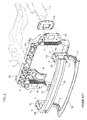
figures 3 ,4 are a perspective view and an exploded perspective view of the preferred embodiment of the motor-vehicle front structure according to the invention, -
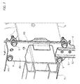
figure 5 is a side view, partially in cross-section, of a detail of the structure offigures 3 ,4 , and -
figures 6 ,7 are further perspective views of some details of the structure offigures 3 ,4 . - Referring initially to
figures 1 ,2 , the known solution which has been already discussed in the foregoing and developed by the same applicant is of a type in which the motor-vehicle structure comprises, in a way which is per se conventional, two longitudinal beans L on whose front ends there are secured in any known way (such as by welding) two strut plates P1. - Also according to a technique which is conventional per se, the known structure further comprises a front cross-member T1, made of aluminium and located forwardly of the two strut plates P1. The ends of the front cross-member T1 are connected by means of two crash-box structures CB to two crash-box plates P2. Both plates P2 and the crash-box structures CB are made of aluminium. The crash-box structures CB are configured so as to be adapted to be deformed and thereby accumulating impact energy in the case of low speed impacts.
- The two crash-box plates P2 are further connected to a lower auxiliary cross-member T2, made of steel, by means of two side supports S having a structure of aluminium configured for being able to accumulate impact energy. Cross-member T2 is specifically provided for transmitting the impact energy to the two supports S in the case of a low speed front impact against a pedestrian.
- Reference FE generally designates a front-end unit for supporting one or more motor-vehicle auxiliary components (not shown). The unit FE is interposed between the front cross-member T1 and the strut plates P1. More specifically, in the case of the known solution shown in
figures 1 ,2 , the front-end unit FE has a single structure of plastic material including a front-end upper cross-member M1, a front-end lower cross-member M2, and two uprights U which connect the ends of the upper and lower cross-members M1, M2 to each other. Within the uprights U of plastic material there are embedded two steel plates P3. - In the above mentioned known solution, the plates P3 forming part of the structure of the front-end unit are interposed in the connection between the crash-box plates P2 and the strut plates P1. This connection is provided by screws V which engage cooperating holes formed in plates P1, P2, P3. Therefore, in the known solution, the crash-box plates P2 are connected to the strut plates P1 with the interposition of plates P3 forming part of the front-end unit.
- The connection of the front-end unit to the motor-vehicle structure is completed by a steel bracket B which has one end connected by means of screws to the central part of the upper cross-member M1 of the front-end unit FE and the opposite end connected to a bracket B1 secured to the central part of the front cross-member T1.
- The preferred embodiment of the present invention is shown in
figures 3-7 . A comparison offigures 3 ,4 withfigures 1 ,2 immediately shows the main differences of the invention with respect to the known solution. In these figures, the parts in common to those offigures 1 ,2 are designated by the same reference signs. - As shown in the drawings, and in particular in
figure 4 , in the case of the invention the two crash-box plates P2 are directly connected to the two strut plates P1, without any interposition of elements forming part of the front-end unit therebetween. As clearly shown infigure 4 , in the case of the invention the plates P3 forming part of the front-end unit according to the known solution have been completely eliminated. In the case of the invention, the front-end unit FE comprises an upper cross-member M1 made of plastic material and a lower cross-member M2 made of plastic material which constitute two elements which are separated from each other and both connected to the two crash-box plates P2. The upper cross-member M1 of the front-end unit FE has its ends connected directly to the two crash-box plates P2. To this end, the two crash-box plates P2, which are placed directly in contact with the two strut plates P1 and are screwed thereto by screws V, include upper portions A projecting above the strut plates P1 in the mounted condition and adapted to form two attachment lugs for screwing thereto of the ends of the upper cross-member M1 of plastic material of the front-end unit. The lower cross-member M2 of plastic material of the front-end unit FE is connected to the crash-box plates P2 with the interposition of the two supports S, which support the auxiliary cross-member T2. - In the case of the embodiment disclosed herein, the two supports S are constituted by two steel sheets, having an L-shape, with vertical portions S1 screwed to the lower ends of the two crash-box plates P2, and two horizontal portions S2 to which the ends of the lower cross-member M2 of plastic material of the front-end unit FE are screwed.
- As shown, in the case of the present invention, not only the two plates P3 of the known solution have been totally eliminated, but also the two uprights U of plastic material, forming part of the known front-end unit have been eliminated. As a consequence, the front-end unit according to the embodiment disclosed herein is constituted by two separate components, i.e. the upper cross-member M1 and the lower cross-member M2. However, the possibility is not excluded of providing the two uprights U so as to have a single structure of plastic material including these uprights U and the two upper and lower cross-members M1, M2, being understood that in the case of the present invention plates P3 are completely eliminated which instead in the known solution are incorporated within the structure of the front-end unit, and being also understood that in the case of the present invention, therefore, the crash-box plates P2 are connected directly and are in contact with the strut plates P1, and that the plates P2 are also used for the connection of the upper cross-member of the front-end unit.
- In the case of the embodiment disclosed herein, the central part of the upper cross-member M1 of the front-end unit FE is connected by means of the bracket B to the central part of the front-cross member T1, similarly to the known solution.
- Naturally, while the principle of the invention remains the same, the details of construction and the embodiments may widely varying with respect to what has been described and illustrated purely by way of example, without departing from the scope of the present invention.
Claims (3)
- Motor-vehicle front structure, comprising:- a pair of longitudinal struts (L), having front ends to which two strut plates (P1) are secured,- a front cross-member (T1) placed in front of the strut plates (P1) and having ends provided with two rearwardly facing cross-member plates (P2), which are rigidly connected to said strut plates (P1),
wherein each cross-member plate is a crash-box plate (P2), connected to said front cross-member (T1) with the interposition of a crash-box structure (CB),- wherein said crash-box plates (P2) are also connected to a lower auxiliary cross-member (T2), through two respective supports (S), each of which has its upper end connected to the respective crash-box plate (P2) and its lower end connected to a respective end of the lower auxiliary cross-member (T2),- a front-end unit (FE) for supporting one or more motor-vehicle auxiliary components, said front-end unit (FE) being interposed between the front cross-member (T1) and the strut plates (P1) and including at least an upper cross-member (M1) constituted of plastic material,- wherein said crash-box plates (P2) are connected directly to said strut plates (P1), with no interposition of elements forming part of the front-end unit (FE) therebetween,
characterized in that:- said front-end unit (FE) includes, beyond said upper cross-member (M1), at least a lower cross-member (M2) also constituted of plastic material,- said upper and lower cross-members (M1, M2) of the front-end unit (FE) are constituted by elements which are separated from each other and both connected at their ends to said crash-box plates (P2), the upper cross-member (M1) of the front-end unit being an element of plastic material having ends screwed directly to the crash-box plates (P2), and the lower cross-member (M2) of the front-end unit being connected to the crash-box plates (P2) through said supports. - Structure according to claim 1, characterized in that said crash-box plates (P2) are directly in contact with said strut plates (P1) and include upper portions (A) that protrude upwardly above said strut plates (P1), so as to define connecting brackets for connection of the ends of said upper cross-member (M1) of the front-end unit (FE).
- Structure according to claim 1 or 2, characterized in that said supports (S) are comprised of two L-shaped metal sheets, having vertical portions (S1) bolted to the lower ends of said crash-box plates (P2) and horizontal portions (S2) to which the ends of said lower crosspiece (M2) of the front-end unit (FE) are screwed.
Applications Claiming Priority (1)
| Application Number | Priority Date | Filing Date | Title |
|---|---|---|---|
| ITTO20140418 | 2014-05-27 |
Publications (2)
| Publication Number | Publication Date |
|---|---|
| EP2949518A1 true EP2949518A1 (en) | 2015-12-02 |
| EP2949518B1 EP2949518B1 (en) | 2017-06-14 |
Family
ID=51399701
Family Applications (1)
| Application Number | Title | Priority Date | Filing Date |
|---|---|---|---|
| EP15159925.5A Not-in-force EP2949518B1 (en) | 2014-05-27 | 2015-03-19 | Motor-vehicle front structure with an improved front-end unit |
Country Status (2)
| Country | Link |
|---|---|
| US (1) | US9211859B1 (en) |
| EP (1) | EP2949518B1 (en) |
Cited By (4)
| Publication number | Priority date | Publication date | Assignee | Title |
|---|---|---|---|---|
| US20160023623A1 (en) * | 2014-07-24 | 2016-01-28 | Magna Exteriors Gmbh | Front-end module |
| WO2018002460A1 (en) * | 2016-06-30 | 2018-01-04 | Valeo Systemes Thermiques | Structure for a motor vehicle front end |
| FR3119129A1 (en) * | 2021-01-28 | 2022-07-29 | Psa Automobiles Sa | Motor vehicle front structure comprising an upper crossmember and vehicle comprising such a front structure |
| WO2024089494A1 (en) * | 2022-10-25 | 2024-05-02 | Stellantis Europe S.P.A. | Motor-vehicle frame assembly provided for absorbing impact energy in case of a frontal impact |
Families Citing this family (17)
| Publication number | Priority date | Publication date | Assignee | Title |
|---|---|---|---|---|
| WO2014162574A1 (en) * | 2013-04-04 | 2014-10-09 | トヨタ自動車株式会社 | Vehicle body end portion structure |
| JP2015168364A (en) * | 2014-03-07 | 2015-09-28 | トヨタ自動車株式会社 | Body front structure |
| FR3037553B1 (en) * | 2015-06-22 | 2019-05-17 | Valeo Systemes Thermiques | SUPPORT STRUCTURE FOR A FRONT FACE MODULE OF A MOTOR VEHICLE AND FRONT PANEL MODULE COMPRISING SAID SUPPORT STRUCTURE |
| US9840286B2 (en) * | 2016-02-12 | 2017-12-12 | Valeo North America, Inc. | Front end module for a vehicle |
| JP6897454B2 (en) | 2017-09-26 | 2021-06-30 | トヨタ自動車株式会社 | Vehicle front body structure |
| JP6879174B2 (en) * | 2017-11-10 | 2021-06-02 | トヨタ自動車株式会社 | Front body structure |
| US10189428B1 (en) * | 2018-03-05 | 2019-01-29 | Honda Motor Co., Ltd. | Mounting assembly for mounting a bumper assembly and a radiator assembly to a vehicle, a vehicle frame, and a vehicle |
| KR102663542B1 (en) * | 2019-05-07 | 2024-05-03 | 현대자동차주식회사 | Front end module frame of vehicle |
| HUE073297T2 (en) * | 2020-04-20 | 2026-01-28 | Arcelormittal | Structural node for a motor vehicle front lower load path, and process for assembling said structural node |
| DE102021102365B4 (en) * | 2021-02-02 | 2023-03-09 | Benteler Automobiltechnik Gmbh | Bumper assembly with additional support |
| JP7735769B2 (en) * | 2021-10-01 | 2025-09-09 | マツダ株式会社 | Vehicle front structure |
| JP7782211B2 (en) * | 2021-11-02 | 2025-12-09 | マツダ株式会社 | Vehicle front structure |
| DE102022123604A1 (en) * | 2022-09-15 | 2024-03-21 | GEDIA Gebrüder Dingerkus GmbH | Motor vehicle with a bumper arrangement |
| US12459577B2 (en) * | 2022-10-13 | 2025-11-04 | Nissan North America, Inc. | Vehicle front end assembly |
| KR20240111534A (en) * | 2023-01-10 | 2024-07-17 | 현대자동차주식회사 | Front end module frame of vehicle |
| KR20240169377A (en) * | 2023-05-24 | 2024-12-03 | 현대자동차주식회사 | Front end module frame of vehicle |
| CN119142419B (en) * | 2024-09-02 | 2025-11-07 | 上汽通用五菱汽车股份有限公司 | Front cabin structure and vehicle |
Citations (5)
| Publication number | Priority date | Publication date | Assignee | Title |
|---|---|---|---|---|
| DE102004014073A1 (en) * | 2004-03-23 | 2005-10-27 | Hbpo Gmbh | Front-end structural module for automobile has hood lock attached to low energy absorbent sub-frame |
| DE102006047419A1 (en) * | 2006-10-06 | 2008-04-10 | Daimler Ag | Carrier part for a front end module of a passenger car |
| FR2919567A1 (en) | 2007-08-03 | 2009-02-06 | Faurecia Bloc Avant | FRONT PANEL OF MOTOR VEHICLE |
| US20100213742A1 (en) * | 2009-02-20 | 2010-08-26 | Dr. Ing. H.C. F. Porsche Aktiengesellschaft | Front end module for a motor vehicle |
| EP2301825A2 (en) | 2009-09-29 | 2011-03-30 | HBPO GmbH | Front end module for a motor vehicle |
Family Cites Families (3)
| Publication number | Priority date | Publication date | Assignee | Title |
|---|---|---|---|---|
| ATE238180T1 (en) * | 2000-10-19 | 2003-05-15 | Benteler Automobiltechnik Gmbh | BUMPER ARRANGEMENT |
| FR2910865B1 (en) * | 2006-12-28 | 2009-04-03 | Plastic Omnium Cie | SUPPORT PART FOR A SHOCK ABSORPTION SYSTEM INTENDED TO BE FITTED AT THE END OF A LONGERON OF A MOTOR VEHICLE |
| FR2967741B1 (en) * | 2010-11-22 | 2012-12-28 | Faurecia Bloc Avant | BI-MATERIAL ENERGY ABSORPTION DEVICE WITH REDUCED THERMAL SENSITIVITY, FRONT PANEL AND MOTOR VEHICLE INCORPORATING SUCH A DEVICE |
-
2015
- 2015-03-19 EP EP15159925.5A patent/EP2949518B1/en not_active Not-in-force
- 2015-05-07 US US14/706,661 patent/US9211859B1/en active Active
Patent Citations (5)
| Publication number | Priority date | Publication date | Assignee | Title |
|---|---|---|---|---|
| DE102004014073A1 (en) * | 2004-03-23 | 2005-10-27 | Hbpo Gmbh | Front-end structural module for automobile has hood lock attached to low energy absorbent sub-frame |
| DE102006047419A1 (en) * | 2006-10-06 | 2008-04-10 | Daimler Ag | Carrier part for a front end module of a passenger car |
| FR2919567A1 (en) | 2007-08-03 | 2009-02-06 | Faurecia Bloc Avant | FRONT PANEL OF MOTOR VEHICLE |
| US20100213742A1 (en) * | 2009-02-20 | 2010-08-26 | Dr. Ing. H.C. F. Porsche Aktiengesellschaft | Front end module for a motor vehicle |
| EP2301825A2 (en) | 2009-09-29 | 2011-03-30 | HBPO GmbH | Front end module for a motor vehicle |
Cited By (9)
| Publication number | Priority date | Publication date | Assignee | Title |
|---|---|---|---|---|
| US20160023623A1 (en) * | 2014-07-24 | 2016-01-28 | Magna Exteriors Gmbh | Front-end module |
| US9487169B2 (en) * | 2014-07-24 | 2016-11-08 | Magna Exteriors Gmbh | Front-end module |
| WO2018002460A1 (en) * | 2016-06-30 | 2018-01-04 | Valeo Systemes Thermiques | Structure for a motor vehicle front end |
| FR3053305A1 (en) * | 2016-06-30 | 2018-01-05 | Valeo Systemes Thermiques | STRUCTURE FOR FRONT PANEL OF MOTOR VEHICLE |
| CN109328158A (en) * | 2016-06-30 | 2019-02-12 | 法雷奥热系统公司 | Structure for the front end of a motor vehicle |
| US10889327B2 (en) | 2016-06-30 | 2021-01-12 | Valeo Systemes Thermiques | Structure for a motor vehicle front end |
| FR3119129A1 (en) * | 2021-01-28 | 2022-07-29 | Psa Automobiles Sa | Motor vehicle front structure comprising an upper crossmember and vehicle comprising such a front structure |
| WO2022162287A1 (en) * | 2021-01-28 | 2022-08-04 | Psa Automobiles Sa | Front structure of a motor vehicle comprising an upper cross-member and vehicle comprising such a front structure |
| WO2024089494A1 (en) * | 2022-10-25 | 2024-05-02 | Stellantis Europe S.P.A. | Motor-vehicle frame assembly provided for absorbing impact energy in case of a frontal impact |
Also Published As
| Publication number | Publication date |
|---|---|
| US9211859B1 (en) | 2015-12-15 |
| US20150343973A1 (en) | 2015-12-03 |
| EP2949518B1 (en) | 2017-06-14 |
Similar Documents
| Publication | Publication Date | Title |
|---|---|---|
| EP2949518B1 (en) | Motor-vehicle front structure with an improved front-end unit | |
| US9352785B2 (en) | Subframe configured to detach upon impact | |
| EP2045170A3 (en) | Front end structure for automobile | |
| US8662566B1 (en) | Multi extension front bumper beam | |
| US9333928B2 (en) | Motor vehicle structure with crash box | |
| US20150076867A1 (en) | Transverse strut | |
| CN101939065A (en) | A skateboard | |
| WO2007074300A3 (en) | Energy absorption system for a motor vehicle | |
| US10717469B2 (en) | Vehicle body front part structure | |
| CN107187499B (en) | Carriage frame and its assemble method | |
| JP6507554B2 (en) | Vehicle packing box mounting bracket | |
| US20160311472A1 (en) | Motor vehicle façade module | |
| EP2572941B1 (en) | Crush box and vehicle bumper apparatus including the same | |
| JP6900882B2 (en) | Vehicle undercarriage | |
| EP2781445B1 (en) | Straddle type vehicle | |
| US10676055B2 (en) | System for energy absorption and load transfer | |
| CN108275097B (en) | Bumper crossbeam for a motor vehicle and motor vehicle having such a bumper crossbeam | |
| JP6799772B2 (en) | Front bumper cover support structure | |
| US9744911B2 (en) | ATV and four-wheeler rack extension | |
| CN205524470U (en) | Body arrangement for the front of the vehicle | |
| KR101220372B1 (en) | Sub frame of suspension system for vehicle | |
| US12319213B2 (en) | Cross-member arrangement for a battery-powered electric vehicle | |
| JP6631378B2 (en) | vehicle | |
| US20110197704A1 (en) | Yoke for pedal assembly with scraper ring | |
| US8757703B2 (en) | Car body with a shear element on one side |
Legal Events
| Date | Code | Title | Description |
|---|---|---|---|
| AK | Designated contracting states |
Kind code of ref document: A1 Designated state(s): AL AT BE BG CH CY CZ DE DK EE ES FI FR GB GR HR HU IE IS IT LI LT LU LV MC MK MT NL NO PL PT RO RS SE SI SK SM TR |
|
| AX | Request for extension of the european patent |
Extension state: BA ME |
|
| PUAI | Public reference made under article 153(3) epc to a published international application that has entered the european phase |
Free format text: ORIGINAL CODE: 0009012 |
|
| 17P | Request for examination filed |
Effective date: 20160309 |
|
| RBV | Designated contracting states (corrected) |
Designated state(s): AL AT BE BG CH CY CZ DE DK EE ES FI FR GB GR HR HU IE IS IT LI LT LU LV MC MK MT NL NO PL PT RO RS SE SI SK SM TR |
|
| GRAP | Despatch of communication of intention to grant a patent |
Free format text: ORIGINAL CODE: EPIDOSNIGR1 |
|
| STAA | Information on the status of an ep patent application or granted ep patent |
Free format text: STATUS: GRANT OF PATENT IS INTENDED |
|
| INTG | Intention to grant announced |
Effective date: 20170130 |
|
| GRAS | Grant fee paid |
Free format text: ORIGINAL CODE: EPIDOSNIGR3 |
|
| GRAA | (expected) grant |
Free format text: ORIGINAL CODE: 0009210 |
|
| STAA | Information on the status of an ep patent application or granted ep patent |
Free format text: STATUS: THE PATENT HAS BEEN GRANTED |
|
| AK | Designated contracting states |
Kind code of ref document: B1 Designated state(s): AL AT BE BG CH CY CZ DE DK EE ES FI FR GB GR HR HU IE IS IT LI LT LU LV MC MK MT NL NO PL PT RO RS SE SI SK SM TR |
|
| REG | Reference to a national code |
Ref country code: GB Ref legal event code: FG4D |
|
| REG | Reference to a national code |
Ref country code: CH Ref legal event code: EP Ref country code: AT Ref legal event code: REF Ref document number: 900636 Country of ref document: AT Kind code of ref document: T Effective date: 20170615 |
|
| REG | Reference to a national code |
Ref country code: IE Ref legal event code: FG4D |
|
| REG | Reference to a national code |
Ref country code: DE Ref legal event code: R096 Ref document number: 602015003054 Country of ref document: DE |
|
| REG | Reference to a national code |
Ref country code: NL Ref legal event code: MP Effective date: 20170614 |
|
| REG | Reference to a national code |
Ref country code: LT Ref legal event code: MG4D |
|
| PG25 | Lapsed in a contracting state [announced via postgrant information from national office to epo] |
Ref country code: LT Free format text: LAPSE BECAUSE OF FAILURE TO SUBMIT A TRANSLATION OF THE DESCRIPTION OR TO PAY THE FEE WITHIN THE PRESCRIBED TIME-LIMIT Effective date: 20170614 Ref country code: NO Free format text: LAPSE BECAUSE OF FAILURE TO SUBMIT A TRANSLATION OF THE DESCRIPTION OR TO PAY THE FEE WITHIN THE PRESCRIBED TIME-LIMIT Effective date: 20170914 Ref country code: FI Free format text: LAPSE BECAUSE OF FAILURE TO SUBMIT A TRANSLATION OF THE DESCRIPTION OR TO PAY THE FEE WITHIN THE PRESCRIBED TIME-LIMIT Effective date: 20170614 Ref country code: GR Free format text: LAPSE BECAUSE OF FAILURE TO SUBMIT A TRANSLATION OF THE DESCRIPTION OR TO PAY THE FEE WITHIN THE PRESCRIBED TIME-LIMIT Effective date: 20170915 Ref country code: HR Free format text: LAPSE BECAUSE OF FAILURE TO SUBMIT A TRANSLATION OF THE DESCRIPTION OR TO PAY THE FEE WITHIN THE PRESCRIBED TIME-LIMIT Effective date: 20170614 |
|
| REG | Reference to a national code |
Ref country code: AT Ref legal event code: MK05 Ref document number: 900636 Country of ref document: AT Kind code of ref document: T Effective date: 20170614 |
|
| PG25 | Lapsed in a contracting state [announced via postgrant information from national office to epo] |
Ref country code: RS Free format text: LAPSE BECAUSE OF FAILURE TO SUBMIT A TRANSLATION OF THE DESCRIPTION OR TO PAY THE FEE WITHIN THE PRESCRIBED TIME-LIMIT Effective date: 20170614 Ref country code: LV Free format text: LAPSE BECAUSE OF FAILURE TO SUBMIT A TRANSLATION OF THE DESCRIPTION OR TO PAY THE FEE WITHIN THE PRESCRIBED TIME-LIMIT Effective date: 20170614 Ref country code: NL Free format text: LAPSE BECAUSE OF FAILURE TO SUBMIT A TRANSLATION OF THE DESCRIPTION OR TO PAY THE FEE WITHIN THE PRESCRIBED TIME-LIMIT Effective date: 20170614 Ref country code: BG Free format text: LAPSE BECAUSE OF FAILURE TO SUBMIT A TRANSLATION OF THE DESCRIPTION OR TO PAY THE FEE WITHIN THE PRESCRIBED TIME-LIMIT Effective date: 20170914 Ref country code: SE Free format text: LAPSE BECAUSE OF FAILURE TO SUBMIT A TRANSLATION OF THE DESCRIPTION OR TO PAY THE FEE WITHIN THE PRESCRIBED TIME-LIMIT Effective date: 20170614 |
|
| PG25 | Lapsed in a contracting state [announced via postgrant information from national office to epo] |
Ref country code: AT Free format text: LAPSE BECAUSE OF FAILURE TO SUBMIT A TRANSLATION OF THE DESCRIPTION OR TO PAY THE FEE WITHIN THE PRESCRIBED TIME-LIMIT Effective date: 20170614 Ref country code: SK Free format text: LAPSE BECAUSE OF FAILURE TO SUBMIT A TRANSLATION OF THE DESCRIPTION OR TO PAY THE FEE WITHIN THE PRESCRIBED TIME-LIMIT Effective date: 20170614 Ref country code: EE Free format text: LAPSE BECAUSE OF FAILURE TO SUBMIT A TRANSLATION OF THE DESCRIPTION OR TO PAY THE FEE WITHIN THE PRESCRIBED TIME-LIMIT Effective date: 20170614 Ref country code: CZ Free format text: LAPSE BECAUSE OF FAILURE TO SUBMIT A TRANSLATION OF THE DESCRIPTION OR TO PAY THE FEE WITHIN THE PRESCRIBED TIME-LIMIT Effective date: 20170614 Ref country code: RO Free format text: LAPSE BECAUSE OF FAILURE TO SUBMIT A TRANSLATION OF THE DESCRIPTION OR TO PAY THE FEE WITHIN THE PRESCRIBED TIME-LIMIT Effective date: 20170614 |
|
| PG25 | Lapsed in a contracting state [announced via postgrant information from national office to epo] |
Ref country code: SM Free format text: LAPSE BECAUSE OF FAILURE TO SUBMIT A TRANSLATION OF THE DESCRIPTION OR TO PAY THE FEE WITHIN THE PRESCRIBED TIME-LIMIT Effective date: 20170614 Ref country code: ES Free format text: LAPSE BECAUSE OF FAILURE TO SUBMIT A TRANSLATION OF THE DESCRIPTION OR TO PAY THE FEE WITHIN THE PRESCRIBED TIME-LIMIT Effective date: 20170614 Ref country code: IS Free format text: LAPSE BECAUSE OF FAILURE TO SUBMIT A TRANSLATION OF THE DESCRIPTION OR TO PAY THE FEE WITHIN THE PRESCRIBED TIME-LIMIT Effective date: 20171014 Ref country code: PL Free format text: LAPSE BECAUSE OF FAILURE TO SUBMIT A TRANSLATION OF THE DESCRIPTION OR TO PAY THE FEE WITHIN THE PRESCRIBED TIME-LIMIT Effective date: 20170614 Ref country code: IT Free format text: LAPSE BECAUSE OF FAILURE TO SUBMIT A TRANSLATION OF THE DESCRIPTION OR TO PAY THE FEE WITHIN THE PRESCRIBED TIME-LIMIT Effective date: 20170614 |
|
| REG | Reference to a national code |
Ref country code: DE Ref legal event code: R097 Ref document number: 602015003054 Country of ref document: DE |
|
| REG | Reference to a national code |
Ref country code: FR Ref legal event code: PLFP Year of fee payment: 4 |
|
| PLBE | No opposition filed within time limit |
Free format text: ORIGINAL CODE: 0009261 |
|
| STAA | Information on the status of an ep patent application or granted ep patent |
Free format text: STATUS: NO OPPOSITION FILED WITHIN TIME LIMIT |
|
| PG25 | Lapsed in a contracting state [announced via postgrant information from national office to epo] |
Ref country code: DK Free format text: LAPSE BECAUSE OF FAILURE TO SUBMIT A TRANSLATION OF THE DESCRIPTION OR TO PAY THE FEE WITHIN THE PRESCRIBED TIME-LIMIT Effective date: 20170614 |
|
| 26N | No opposition filed |
Effective date: 20180315 |
|
| PG25 | Lapsed in a contracting state [announced via postgrant information from national office to epo] |
Ref country code: SI Free format text: LAPSE BECAUSE OF FAILURE TO SUBMIT A TRANSLATION OF THE DESCRIPTION OR TO PAY THE FEE WITHIN THE PRESCRIBED TIME-LIMIT Effective date: 20170614 |
|
| REG | Reference to a national code |
Ref country code: CH Ref legal event code: PL |
|
| PG25 | Lapsed in a contracting state [announced via postgrant information from national office to epo] |
Ref country code: MC Free format text: LAPSE BECAUSE OF FAILURE TO SUBMIT A TRANSLATION OF THE DESCRIPTION OR TO PAY THE FEE WITHIN THE PRESCRIBED TIME-LIMIT Effective date: 20170614 |
|
| REG | Reference to a national code |
Ref country code: BE Ref legal event code: MM Effective date: 20180331 |
|
| REG | Reference to a national code |
Ref country code: IE Ref legal event code: MM4A |
|
| PG25 | Lapsed in a contracting state [announced via postgrant information from national office to epo] |
Ref country code: LU Free format text: LAPSE BECAUSE OF NON-PAYMENT OF DUE FEES Effective date: 20180319 |
|
| PG25 | Lapsed in a contracting state [announced via postgrant information from national office to epo] |
Ref country code: IE Free format text: LAPSE BECAUSE OF NON-PAYMENT OF DUE FEES Effective date: 20180319 |
|
| PG25 | Lapsed in a contracting state [announced via postgrant information from national office to epo] |
Ref country code: BE Free format text: LAPSE BECAUSE OF NON-PAYMENT OF DUE FEES Effective date: 20180331 Ref country code: LI Free format text: LAPSE BECAUSE OF NON-PAYMENT OF DUE FEES Effective date: 20180331 Ref country code: CH Free format text: LAPSE BECAUSE OF NON-PAYMENT OF DUE FEES Effective date: 20180331 |
|
| GBPC | Gb: european patent ceased through non-payment of renewal fee |
Effective date: 20190319 |
|
| PG25 | Lapsed in a contracting state [announced via postgrant information from national office to epo] |
Ref country code: GB Free format text: LAPSE BECAUSE OF NON-PAYMENT OF DUE FEES Effective date: 20190319 Ref country code: MT Free format text: LAPSE BECAUSE OF NON-PAYMENT OF DUE FEES Effective date: 20180319 |
|
| PG25 | Lapsed in a contracting state [announced via postgrant information from national office to epo] |
Ref country code: TR Free format text: LAPSE BECAUSE OF FAILURE TO SUBMIT A TRANSLATION OF THE DESCRIPTION OR TO PAY THE FEE WITHIN THE PRESCRIBED TIME-LIMIT Effective date: 20170614 |
|
| PG25 | Lapsed in a contracting state [announced via postgrant information from national office to epo] |
Ref country code: PT Free format text: LAPSE BECAUSE OF FAILURE TO SUBMIT A TRANSLATION OF THE DESCRIPTION OR TO PAY THE FEE WITHIN THE PRESCRIBED TIME-LIMIT Effective date: 20170614 |
|
| PG25 | Lapsed in a contracting state [announced via postgrant information from national office to epo] |
Ref country code: HU Free format text: LAPSE BECAUSE OF FAILURE TO SUBMIT A TRANSLATION OF THE DESCRIPTION OR TO PAY THE FEE WITHIN THE PRESCRIBED TIME-LIMIT; INVALID AB INITIO Effective date: 20150319 Ref country code: MK Free format text: LAPSE BECAUSE OF NON-PAYMENT OF DUE FEES Effective date: 20170614 Ref country code: CY Free format text: LAPSE BECAUSE OF FAILURE TO SUBMIT A TRANSLATION OF THE DESCRIPTION OR TO PAY THE FEE WITHIN THE PRESCRIBED TIME-LIMIT Effective date: 20170614 |
|
| PG25 | Lapsed in a contracting state [announced via postgrant information from national office to epo] |
Ref country code: AL Free format text: LAPSE BECAUSE OF FAILURE TO SUBMIT A TRANSLATION OF THE DESCRIPTION OR TO PAY THE FEE WITHIN THE PRESCRIBED TIME-LIMIT Effective date: 20170614 |
|
| PGFP | Annual fee paid to national office [announced via postgrant information from national office to epo] |
Ref country code: DE Payment date: 20240220 Year of fee payment: 10 |
|
| PGFP | Annual fee paid to national office [announced via postgrant information from national office to epo] |
Ref country code: FR Payment date: 20240221 Year of fee payment: 10 |
|
| REG | Reference to a national code |
Ref country code: DE Ref legal event code: R119 Ref document number: 602015003054 Country of ref document: DE |
|
| PG25 | Lapsed in a contracting state [announced via postgrant information from national office to epo] |
Ref country code: DE Free format text: LAPSE BECAUSE OF NON-PAYMENT OF DUE FEES Effective date: 20251001 |
|
| PG25 | Lapsed in a contracting state [announced via postgrant information from national office to epo] |
Ref country code: FR Free format text: LAPSE BECAUSE OF NON-PAYMENT OF DUE FEES Effective date: 20250331 |