EP2949461B1 - Print substrate - Google Patents
Print substrate Download PDFInfo
- Publication number
- EP2949461B1 EP2949461B1 EP14169903.3A EP14169903A EP2949461B1 EP 2949461 B1 EP2949461 B1 EP 2949461B1 EP 14169903 A EP14169903 A EP 14169903A EP 2949461 B1 EP2949461 B1 EP 2949461B1
- Authority
- EP
- European Patent Office
- Prior art keywords
- layer
- print substrate
- substrate according
- print carrier
- Prior art date
- Legal status (The legal status is an assumption and is not a legal conclusion. Google has not performed a legal analysis and makes no representation as to the accuracy of the status listed.)
- Active
Links
- 239000000758 substrate Substances 0.000 title claims description 58
- 230000003746 surface roughness Effects 0.000 claims description 21
- 239000000463 material Substances 0.000 claims description 17
- 239000000203 mixture Substances 0.000 claims description 8
- 229920003023 plastic Polymers 0.000 claims description 8
- 239000004033 plastic Substances 0.000 claims description 8
- 229920000098 polyolefin Polymers 0.000 claims description 7
- 239000004800 polyvinyl chloride Substances 0.000 claims description 7
- 229920000642 polymer Polymers 0.000 claims description 6
- 239000003365 glass fiber Substances 0.000 claims description 3
- 239000011888 foil Substances 0.000 claims 7
- 239000010410 layer Substances 0.000 description 38
- 239000002985 plastic film Substances 0.000 description 34
- 229920006255 plastic film Polymers 0.000 description 34
- 238000007639 printing Methods 0.000 description 29
- 239000000975 dye Substances 0.000 description 22
- 238000004519 manufacturing process Methods 0.000 description 10
- 238000005299 abrasion Methods 0.000 description 9
- 238000000034 method Methods 0.000 description 5
- 229920000915 polyvinyl chloride Polymers 0.000 description 5
- 239000002699 waste material Substances 0.000 description 5
- 238000004026 adhesive bonding Methods 0.000 description 3
- 230000001070 adhesive effect Effects 0.000 description 3
- 230000006378 damage Effects 0.000 description 3
- 238000004049 embossing Methods 0.000 description 3
- 230000007613 environmental effect Effects 0.000 description 3
- 239000000835 fiber Substances 0.000 description 3
- 239000002344 surface layer Substances 0.000 description 3
- 229920000704 biodegradable plastic Polymers 0.000 description 2
- 238000001035 drying Methods 0.000 description 2
- 230000000694 effects Effects 0.000 description 2
- 239000000945 filler Substances 0.000 description 2
- 239000006260 foam Substances 0.000 description 2
- 238000009413 insulation Methods 0.000 description 2
- 230000003993 interaction Effects 0.000 description 2
- 239000013067 intermediate product Substances 0.000 description 2
- JVTAAEKCZFNVCJ-UHFFFAOYSA-N lactic acid Chemical compound CC(O)C(O)=O JVTAAEKCZFNVCJ-UHFFFAOYSA-N 0.000 description 2
- 230000001737 promoting effect Effects 0.000 description 2
- 238000007789 sealing Methods 0.000 description 2
- 230000008646 thermal stress Effects 0.000 description 2
- 238000003466 welding Methods 0.000 description 2
- 238000009736 wetting Methods 0.000 description 2
- 241001465754 Metazoa Species 0.000 description 1
- 239000004793 Polystyrene Substances 0.000 description 1
- 229920002472 Starch Polymers 0.000 description 1
- 238000010521 absorption reaction Methods 0.000 description 1
- 239000002253 acid Substances 0.000 description 1
- 230000009471 action Effects 0.000 description 1
- 239000000654 additive Substances 0.000 description 1
- 239000000853 adhesive Substances 0.000 description 1
- 239000012790 adhesive layer Substances 0.000 description 1
- 239000010426 asphalt Substances 0.000 description 1
- 239000011449 brick Substances 0.000 description 1
- 239000001913 cellulose Substances 0.000 description 1
- 229920002678 cellulose Polymers 0.000 description 1
- 235000010980 cellulose Nutrition 0.000 description 1
- 239000012459 cleaning agent Substances 0.000 description 1
- 239000003086 colorant Substances 0.000 description 1
- 150000001875 compounds Chemical class 0.000 description 1
- 238000005520 cutting process Methods 0.000 description 1
- 230000032798 delamination Effects 0.000 description 1
- 235000013305 food Nutrition 0.000 description 1
- 239000011521 glass Substances 0.000 description 1
- 238000007689 inspection Methods 0.000 description 1
- 235000014655 lactic acid Nutrition 0.000 description 1
- 239000004310 lactic acid Substances 0.000 description 1
- 239000007788 liquid Substances 0.000 description 1
- 239000002184 metal Substances 0.000 description 1
- 230000003287 optical effect Effects 0.000 description 1
- 239000000049 pigment Substances 0.000 description 1
- 239000004014 plasticizer Substances 0.000 description 1
- 229920002223 polystyrene Polymers 0.000 description 1
- 238000002360 preparation method Methods 0.000 description 1
- 230000008569 process Effects 0.000 description 1
- 238000004886 process control Methods 0.000 description 1
- 239000000047 product Substances 0.000 description 1
- 238000004064 recycling Methods 0.000 description 1
- 230000009467 reduction Effects 0.000 description 1
- 238000007788 roughening Methods 0.000 description 1
- 230000001953 sensory effect Effects 0.000 description 1
- 238000007493 shaping process Methods 0.000 description 1
- 239000003381 stabilizer Substances 0.000 description 1
- 239000008107 starch Substances 0.000 description 1
- 235000019698 starch Nutrition 0.000 description 1
- 238000003860 storage Methods 0.000 description 1
- 239000000126 substance Substances 0.000 description 1
- XLYOFNOQVPJJNP-UHFFFAOYSA-N water Substances O XLYOFNOQVPJJNP-UHFFFAOYSA-N 0.000 description 1
- 239000002023 wood Substances 0.000 description 1
Images
Classifications
-
- G—PHYSICS
- G09—EDUCATION; CRYPTOGRAPHY; DISPLAY; ADVERTISING; SEALS
- G09F—DISPLAYING; ADVERTISING; SIGNS; LABELS OR NAME-PLATES; SEALS
- G09F3/00—Labels, tag tickets, or similar identification or indication means; Seals; Postage or like stamps
- G09F3/08—Fastening or securing by means not forming part of the material of the label itself
- G09F3/10—Fastening or securing by means not forming part of the material of the label itself by an adhesive layer
-
- B—PERFORMING OPERATIONS; TRANSPORTING
- B32—LAYERED PRODUCTS
- B32B—LAYERED PRODUCTS, i.e. PRODUCTS BUILT-UP OF STRATA OF FLAT OR NON-FLAT, e.g. CELLULAR OR HONEYCOMB, FORM
- B32B5/00—Layered products characterised by the non- homogeneity or physical structure, i.e. comprising a fibrous, filamentary, particulate or foam layer; Layered products characterised by having a layer differing constitutionally or physically in different parts
- B32B5/02—Layered products characterised by the non- homogeneity or physical structure, i.e. comprising a fibrous, filamentary, particulate or foam layer; Layered products characterised by having a layer differing constitutionally or physically in different parts characterised by structural features of a fibrous or filamentary layer
- B32B5/022—Non-woven fabric
-
- B—PERFORMING OPERATIONS; TRANSPORTING
- B29—WORKING OF PLASTICS; WORKING OF SUBSTANCES IN A PLASTIC STATE IN GENERAL
- B29C—SHAPING OR JOINING OF PLASTICS; SHAPING OF MATERIAL IN A PLASTIC STATE, NOT OTHERWISE PROVIDED FOR; AFTER-TREATMENT OF THE SHAPED PRODUCTS, e.g. REPAIRING
- B29C59/00—Surface shaping of articles, e.g. embossing; Apparatus therefor
- B29C59/005—Surface shaping of articles, e.g. embossing; Apparatus therefor characterised by the choice of material
-
- B—PERFORMING OPERATIONS; TRANSPORTING
- B29—WORKING OF PLASTICS; WORKING OF SUBSTANCES IN A PLASTIC STATE IN GENERAL
- B29C—SHAPING OR JOINING OF PLASTICS; SHAPING OF MATERIAL IN A PLASTIC STATE, NOT OTHERWISE PROVIDED FOR; AFTER-TREATMENT OF THE SHAPED PRODUCTS, e.g. REPAIRING
- B29C65/00—Joining or sealing of preformed parts, e.g. welding of plastics materials; Apparatus therefor
- B29C65/76—Making non-permanent or releasable joints
-
- B—PERFORMING OPERATIONS; TRANSPORTING
- B29—WORKING OF PLASTICS; WORKING OF SUBSTANCES IN A PLASTIC STATE IN GENERAL
- B29C—SHAPING OR JOINING OF PLASTICS; SHAPING OF MATERIAL IN A PLASTIC STATE, NOT OTHERWISE PROVIDED FOR; AFTER-TREATMENT OF THE SHAPED PRODUCTS, e.g. REPAIRING
- B29C65/00—Joining or sealing of preformed parts, e.g. welding of plastics materials; Apparatus therefor
- B29C65/78—Means for handling the parts to be joined, e.g. for making containers or hollow articles, e.g. means for handling sheets, plates, web-like materials, tubular articles, hollow articles or elements to be joined therewith; Means for discharging the joined articles from the joining apparatus
- B29C65/7858—Means for handling the parts to be joined, e.g. for making containers or hollow articles, e.g. means for handling sheets, plates, web-like materials, tubular articles, hollow articles or elements to be joined therewith; Means for discharging the joined articles from the joining apparatus characterised by the feeding movement of the parts to be joined
- B29C65/7888—Means for handling of moving sheets or webs
-
- B—PERFORMING OPERATIONS; TRANSPORTING
- B32—LAYERED PRODUCTS
- B32B—LAYERED PRODUCTS, i.e. PRODUCTS BUILT-UP OF STRATA OF FLAT OR NON-FLAT, e.g. CELLULAR OR HONEYCOMB, FORM
- B32B27/00—Layered products comprising a layer of synthetic resin
- B32B27/06—Layered products comprising a layer of synthetic resin as the main or only constituent of a layer, which is next to another layer of the same or of a different material
- B32B27/065—Layered products comprising a layer of synthetic resin as the main or only constituent of a layer, which is next to another layer of the same or of a different material of foam
-
- B—PERFORMING OPERATIONS; TRANSPORTING
- B32—LAYERED PRODUCTS
- B32B—LAYERED PRODUCTS, i.e. PRODUCTS BUILT-UP OF STRATA OF FLAT OR NON-FLAT, e.g. CELLULAR OR HONEYCOMB, FORM
- B32B27/00—Layered products comprising a layer of synthetic resin
- B32B27/12—Layered products comprising a layer of synthetic resin next to a fibrous or filamentary layer
-
- B—PERFORMING OPERATIONS; TRANSPORTING
- B32—LAYERED PRODUCTS
- B32B—LAYERED PRODUCTS, i.e. PRODUCTS BUILT-UP OF STRATA OF FLAT OR NON-FLAT, e.g. CELLULAR OR HONEYCOMB, FORM
- B32B27/00—Layered products comprising a layer of synthetic resin
- B32B27/30—Layered products comprising a layer of synthetic resin comprising vinyl (co)polymers; comprising acrylic (co)polymers
- B32B27/304—Layered products comprising a layer of synthetic resin comprising vinyl (co)polymers; comprising acrylic (co)polymers comprising vinyl halide (co)polymers, e.g. PVC, PVDC, PVF, PVDF
-
- B—PERFORMING OPERATIONS; TRANSPORTING
- B32—LAYERED PRODUCTS
- B32B—LAYERED PRODUCTS, i.e. PRODUCTS BUILT-UP OF STRATA OF FLAT OR NON-FLAT, e.g. CELLULAR OR HONEYCOMB, FORM
- B32B27/00—Layered products comprising a layer of synthetic resin
- B32B27/32—Layered products comprising a layer of synthetic resin comprising polyolefins
-
- B—PERFORMING OPERATIONS; TRANSPORTING
- B32—LAYERED PRODUCTS
- B32B—LAYERED PRODUCTS, i.e. PRODUCTS BUILT-UP OF STRATA OF FLAT OR NON-FLAT, e.g. CELLULAR OR HONEYCOMB, FORM
- B32B37/00—Methods or apparatus for laminating, e.g. by curing or by ultrasonic bonding
- B32B37/14—Methods or apparatus for laminating, e.g. by curing or by ultrasonic bonding characterised by the properties of the layers
- B32B37/16—Methods or apparatus for laminating, e.g. by curing or by ultrasonic bonding characterised by the properties of the layers with all layers existing as coherent layers before laminating
- B32B37/20—Methods or apparatus for laminating, e.g. by curing or by ultrasonic bonding characterised by the properties of the layers with all layers existing as coherent layers before laminating involving the assembly of continuous webs only
- B32B37/203—One or more of the layers being plastic
-
- B—PERFORMING OPERATIONS; TRANSPORTING
- B32—LAYERED PRODUCTS
- B32B—LAYERED PRODUCTS, i.e. PRODUCTS BUILT-UP OF STRATA OF FLAT OR NON-FLAT, e.g. CELLULAR OR HONEYCOMB, FORM
- B32B38/00—Ancillary operations in connection with laminating processes
- B32B38/0012—Mechanical treatment, e.g. roughening, deforming, stretching
-
- B—PERFORMING OPERATIONS; TRANSPORTING
- B32—LAYERED PRODUCTS
- B32B—LAYERED PRODUCTS, i.e. PRODUCTS BUILT-UP OF STRATA OF FLAT OR NON-FLAT, e.g. CELLULAR OR HONEYCOMB, FORM
- B32B38/00—Ancillary operations in connection with laminating processes
- B32B38/14—Printing or colouring
- B32B38/145—Printing
-
- A—HUMAN NECESSITIES
- A47—FURNITURE; DOMESTIC ARTICLES OR APPLIANCES; COFFEE MILLS; SPICE MILLS; SUCTION CLEANERS IN GENERAL
- A47B—TABLES; DESKS; OFFICE FURNITURE; CABINETS; DRAWERS; GENERAL DETAILS OF FURNITURE
- A47B13/00—Details of tables or desks
- A47B13/08—Table tops; Rims therefor
- A47B13/086—Table tops provided with a protecting coating made of veneer, linoleum, paper or the like
-
- B—PERFORMING OPERATIONS; TRANSPORTING
- B29—WORKING OF PLASTICS; WORKING OF SUBSTANCES IN A PLASTIC STATE IN GENERAL
- B29K—INDEXING SCHEME ASSOCIATED WITH SUBCLASSES B29B, B29C OR B29D, RELATING TO MOULDING MATERIALS OR TO MATERIALS FOR MOULDS, REINFORCEMENTS, FILLERS OR PREFORMED PARTS, e.g. INSERTS
- B29K2027/00—Use of polyvinylhalogenides or derivatives thereof as moulding material
- B29K2027/06—PVC, i.e. polyvinylchloride
-
- B—PERFORMING OPERATIONS; TRANSPORTING
- B29—WORKING OF PLASTICS; WORKING OF SUBSTANCES IN A PLASTIC STATE IN GENERAL
- B29K—INDEXING SCHEME ASSOCIATED WITH SUBCLASSES B29B, B29C OR B29D, RELATING TO MOULDING MATERIALS OR TO MATERIALS FOR MOULDS, REINFORCEMENTS, FILLERS OR PREFORMED PARTS, e.g. INSERTS
- B29K2055/00—Use of specific polymers obtained by polymerisation reactions only involving carbon-to-carbon unsaturated bonds, not provided for in a single one of main groups B29K2023/00 - B29K2049/00, e.g. having a vinyl group, as moulding material
-
- B—PERFORMING OPERATIONS; TRANSPORTING
- B29—WORKING OF PLASTICS; WORKING OF SUBSTANCES IN A PLASTIC STATE IN GENERAL
- B29K—INDEXING SCHEME ASSOCIATED WITH SUBCLASSES B29B, B29C OR B29D, RELATING TO MOULDING MATERIALS OR TO MATERIALS FOR MOULDS, REINFORCEMENTS, FILLERS OR PREFORMED PARTS, e.g. INSERTS
- B29K2627/00—Use of polyvinylhalogenides or derivatives thereof for preformed parts, e.g. for inserts
- B29K2627/06—PVC, i.e. polyvinylchloride
-
- B—PERFORMING OPERATIONS; TRANSPORTING
- B29—WORKING OF PLASTICS; WORKING OF SUBSTANCES IN A PLASTIC STATE IN GENERAL
- B29K—INDEXING SCHEME ASSOCIATED WITH SUBCLASSES B29B, B29C OR B29D, RELATING TO MOULDING MATERIALS OR TO MATERIALS FOR MOULDS, REINFORCEMENTS, FILLERS OR PREFORMED PARTS, e.g. INSERTS
- B29K2655/00—Use of specific polymers obtained by polymerisation reactions only involving carbon-to-carbon unsaturated bonds, not provided for in a single one of main groups B29K2623/00 - B29K2649/00, e.g. having a vinyl group, for preformed parts, e.g. for inserts
-
- B—PERFORMING OPERATIONS; TRANSPORTING
- B29—WORKING OF PLASTICS; WORKING OF SUBSTANCES IN A PLASTIC STATE IN GENERAL
- B29L—INDEXING SCHEME ASSOCIATED WITH SUBCLASS B29C, RELATING TO PARTICULAR ARTICLES
- B29L2031/00—Other particular articles
- B29L2031/744—Labels, badges, e.g. marker sleeves
-
- B—PERFORMING OPERATIONS; TRANSPORTING
- B32—LAYERED PRODUCTS
- B32B—LAYERED PRODUCTS, i.e. PRODUCTS BUILT-UP OF STRATA OF FLAT OR NON-FLAT, e.g. CELLULAR OR HONEYCOMB, FORM
- B32B2250/00—Layers arrangement
- B32B2250/03—3 layers
-
- B—PERFORMING OPERATIONS; TRANSPORTING
- B32—LAYERED PRODUCTS
- B32B—LAYERED PRODUCTS, i.e. PRODUCTS BUILT-UP OF STRATA OF FLAT OR NON-FLAT, e.g. CELLULAR OR HONEYCOMB, FORM
- B32B2250/00—Layers arrangement
- B32B2250/04—4 layers
-
- B—PERFORMING OPERATIONS; TRANSPORTING
- B32—LAYERED PRODUCTS
- B32B—LAYERED PRODUCTS, i.e. PRODUCTS BUILT-UP OF STRATA OF FLAT OR NON-FLAT, e.g. CELLULAR OR HONEYCOMB, FORM
- B32B2255/00—Coating on the layer surface
- B32B2255/10—Coating on the layer surface on synthetic resin layer or on natural or synthetic rubber layer
-
- B—PERFORMING OPERATIONS; TRANSPORTING
- B32—LAYERED PRODUCTS
- B32B—LAYERED PRODUCTS, i.e. PRODUCTS BUILT-UP OF STRATA OF FLAT OR NON-FLAT, e.g. CELLULAR OR HONEYCOMB, FORM
- B32B2255/00—Coating on the layer surface
- B32B2255/24—Organic non-macromolecular coating
-
- B—PERFORMING OPERATIONS; TRANSPORTING
- B32—LAYERED PRODUCTS
- B32B—LAYERED PRODUCTS, i.e. PRODUCTS BUILT-UP OF STRATA OF FLAT OR NON-FLAT, e.g. CELLULAR OR HONEYCOMB, FORM
- B32B2262/00—Composition or structural features of fibres which form a fibrous or filamentary layer or are present as additives
- B32B2262/10—Inorganic fibres
- B32B2262/101—Glass fibres
-
- B—PERFORMING OPERATIONS; TRANSPORTING
- B32—LAYERED PRODUCTS
- B32B—LAYERED PRODUCTS, i.e. PRODUCTS BUILT-UP OF STRATA OF FLAT OR NON-FLAT, e.g. CELLULAR OR HONEYCOMB, FORM
- B32B2327/00—Polyvinylhalogenides
- B32B2327/06—PVC, i.e. polyvinylchloride
-
- B—PERFORMING OPERATIONS; TRANSPORTING
- B32—LAYERED PRODUCTS
- B32B—LAYERED PRODUCTS, i.e. PRODUCTS BUILT-UP OF STRATA OF FLAT OR NON-FLAT, e.g. CELLULAR OR HONEYCOMB, FORM
- B32B2355/00—Specific polymers obtained by polymerisation reactions only involving carbon-to-carbon unsaturated bonds, not provided for in a single one of index codes B32B2323/00 - B32B2333/00
-
- B—PERFORMING OPERATIONS; TRANSPORTING
- B32—LAYERED PRODUCTS
- B32B—LAYERED PRODUCTS, i.e. PRODUCTS BUILT-UP OF STRATA OF FLAT OR NON-FLAT, e.g. CELLULAR OR HONEYCOMB, FORM
- B32B2519/00—Labels, badges
-
- G—PHYSICS
- G09—EDUCATION; CRYPTOGRAPHY; DISPLAY; ADVERTISING; SEALS
- G09F—DISPLAYING; ADVERTISING; SIGNS; LABELS OR NAME-PLATES; SEALS
- G09F3/00—Labels, tag tickets, or similar identification or indication means; Seals; Postage or like stamps
- G09F3/02—Forms or constructions
- G09F2003/023—Adhesive
- G09F2003/0232—Resistance to heat
-
- Y—GENERAL TAGGING OF NEW TECHNOLOGICAL DEVELOPMENTS; GENERAL TAGGING OF CROSS-SECTIONAL TECHNOLOGIES SPANNING OVER SEVERAL SECTIONS OF THE IPC; TECHNICAL SUBJECTS COVERED BY FORMER USPC CROSS-REFERENCE ART COLLECTIONS [XRACs] AND DIGESTS
- Y10—TECHNICAL SUBJECTS COVERED BY FORMER USPC
- Y10T—TECHNICAL SUBJECTS COVERED BY FORMER US CLASSIFICATION
- Y10T156/00—Adhesive bonding and miscellaneous chemical manufacture
- Y10T156/10—Methods of surface bonding and/or assembly therefor
- Y10T156/1002—Methods of surface bonding and/or assembly therefor with permanent bending or reshaping or surface deformation of self sustaining lamina
- Y10T156/1039—Surface deformation only of sandwich or lamina [e.g., embossed panels]
- Y10T156/1041—Subsequent to lamination
Definitions
- the invention relates to a print carrier with a plastic film of a polymer composition which at least partially polyvinyl chloride (PVC) or polyolefin (PO) includes, wherein the plastic film on one side carries a printing layer of at least one dye.
- PVC polyvinyl chloride
- PO polyolefin
- Generic printing substrates are known in particular in the form of stickers from the prior art for a long time, which is why it does not require a documentary evidence at this point. They are mainly used for gluing free surfaces such as in particular on walls, floors, pieces of furniture or the like. They serve primarily to individualize the named areas and serve as advertising medium, especially in the public sector.
- a general layer structure is, for example, with the CN 103114706 A shown. This describes a printed floor covering consisting of a plurality of layers.
- the layer structure is divided into a surface layer, a lower layer and a foam layer.
- the foam layer is in this case arranged between the surface layer and the lower layer.
- the surface layer consists of top to bottom, an abrasion protection layer, a print layer and a PVC layer.
- a disadvantage of this configuration is in particular the high production costs, a comparatively poor quality of the printed image, the thermal resistance.
- the object of the invention is therefore, starting from the above to provide a print carrier which avoids the disadvantages of generic print media described above.
- the invention proposes a generic print carrier, which is characterized in that the print layer is formed without sealing, wherein the print layer forms the user-side outside of the print carrier and that the plastic film is bonded cohesively with its unprinted side with a substrate, said the backing has a material thickness of at least 1.5 mm and consists at least in part of a foamed and recyclable polymer composition, and wherein the print layer contains 5-40 ml / m 2 of the at least one dye is printed on the plastic film, wherein the print carrier has a total print layer-side surface roughness of at least 10 m.
- the disadvantages of the known from the prior art print carrier is achieved in that the printed plastic film is no longer bonded to foreign surfaces, in particular furniture surfaces, walls and floors, but is already arranged on a substrate according to the invention, with the mechanical and thermal advantages Conventional labels based on unknown from the prior art synergy between the printing layer, the plastic film and the base and their technical design.
- the print carrier according to the invention consists of a plastic film, which is bonded cohesively to a flexible and flexible base. Cohesive in the sense of the invention in this case denotes in particular gluing, welding or the like.
- Cohesive in the sense of the invention in this case denotes in particular gluing, welding or the like.
- an intimate connection between the plastic film and the base is thereby realized and a detachment of the components from each other is prevented.
- the print carrier is due to its flexible and flexible components, in particular the pad and the plastic film, able to compensate for unevenness of the substrate, especially in brick walls, tile floors and the like.
- the optical uniformity of the printing motif is thus always guaranteed independently of the respective background.
- the pad according to the invention is also able to absorb compressive layer-side mechanical loads and thus ensures despite any unevenness of the ground for a uniform power and thus reduces abrasion and wear of the print layer.
- the intended use of the print carrier as an advertising medium thus, in contrast to known from the prior art print media is not affected by the background and / or mechanical action.
- the base for this purpose has a material thickness of at least 1.5 mm.
- the flexibility achievable thereby makes it possible, in particular, to mount the underlay and / or the print carrier as a roll product, preferably in the dimensions 4 mx 30 m. As a result, a continuous printing of the substrate is made possible and the production optimized in terms of their efficiency.
- the print carrier according to the invention is also reusable, since it does not have to be bonded to the substrate for stationary arrangement, but at least on flat and oblique surfaces by the foamed design of the pad in conjunction with its composition of the invention for a slip-resistant arrangement of the print carrier.
- a destruction of the print carrier and damage to the substrate is thus completely avoided.
- the print carrier preferably has suitable holding means for hanging arrangement.
- the print carrier can be glued to the substrate as in the prior art, whereby a particularly simple and stable connection with the vertical surface is formed.
- the print carrier continues to provide the advantages of the invention in terms of the compensation of unevenness of the ground.
- the pad consists of a recyclable polymer composition.
- essentially exclusively recyclable components such as in particular, polyvinyl chloride, polystyrene, polyolefins and the like are preferably used for this purpose.
- the recyclable composition may contain additives, plasticizers, pigments, fillers, especially fiber fillers, and stabilizers.
- the pad according to the invention can therefore be fed to the recycling cycle and can be produced in a resource-saving manner.
- the pad consists of biodegradable plastics, in particular starch, lactic acid, cellulose or Polyhydroxyalkanoatbasis, in particular polyhydroxybutyric acid.
- Biodegradable plastics used can preferably be set a minimum period of use and then disposed of environmentally friendly.
- this is highly advantageous in view of the large number of waste materials produced after the intended use.
- the plastic film is formed from a polymer composition which at least partially comprises polyvinyl chloride, polyolefin or, preferably, polyolefin copolymers includes.
- the plastic film is thus mechanically extremely stable, resistant to abrasion and also recyclable.
- it is optimally suitable as a substrate for receiving the printing layer, since there is an abrasion-resistant interaction between the dye according to the invention and the abovementioned materials.
- the print layer is thus at least partially protected against abrasion via the plastic film.
- the plastic film preferably has a material thickness of 0.1-0.4 mm, preferably 0.2 mm.
- in combination with the material thickness of the pad results in a particularly flexible, mechanically stable print carrier, which can be printed in high quality in a simple manner.
- the plastic film is constructed in two layers and on the pad side has a fiber layer, in particular a glass fiber fleece for advantageous increase in the stability of the print carrier.
- a fiber layer in particular a glass fiber fleece for advantageous increase in the stability of the print carrier.
- the fiber layer advantageously increases the stiffness of the print carrier in the event of temperature fluctuations, which is particularly advantageous in applications outside of closed spaces.
- the print carrier has a print layer-side surface roughness of at least 10 m, preferably 10 to 30 m, more preferably 13 to 20 m.
- Surface roughness in the sense of the invention denotes the distance between the averaged maximum height and the averaged minimum height of the surface.
- the print carrier by the surface roughness according to the invention comparatively good adhesive properties, which, inter alia, when inspecting the print carrier in particular when used as a floor covering, in the arrangement of objects on the print carrier in particular when used as a table top or in the sensory scanning of the print carrier advantageous when used as a mouse pad.
- the surface roughness in this respect ensures improved slip resistance during the inspection and / or storage of objects on the print carrier.
- this provides slip resistance on dry, water-wet, water-moist and oily or greasy print media.
- This is particularly advantageous where the risk of surface wetting with water or other liquids, in particular Oil exists.
- the surface roughness according to the invention even with such wetting an advantageous slip resistance of the print carrier is given, whereby in particular glasses and the like can be placed on this slip-proof.
- the surface roughness provides improved sensor accuracy when used as a mouse pad due to the relatively large scannable surface of the print carrier.
- the surface roughness is realized in that the plastic film and / or the base pressure-layer side are designed in relief.
- Relief-like in the sense of the invention means that the respective surface has regularly or irregularly arranged elevations and depressions, which are designed in terms of their height difference such that the print carrier still has the aforementioned surface roughness after printing the plastic film with the print layer.
- the printing layer is printed with a dye quantity of 5 to 40 ml / m 2 , preferably 10 to 30 ml / m 2 and more preferably 15 to 20 ml / m 2 . It has been found that such an amount of dye, especially in conjunction with the relief-like configuration of the plastic film, leads to the desired surface roughness, without impairing the image quality of the printed motif.
- various printing methods with different types of dyes are suitable for printing on the plastic film.
- the print layer consists of at least one dye. In particular black and white subjects, the use of a single dye is sufficient, whereby the production of the print carrier is simplified.
- the printing layer from a dye system comprising 4 dyes, in particular blue, purple, yellow and black, also known as CMYK (cyan, magenta, yellow, key) system.
- CMYK cyan, magenta, yellow, key
- the CMYK system can be supplemented to improve the printed image by two other colors, in particular orange and green.
- the at least one dye or the respective dye system is preferably formed from at least one UV-curable dye, which advantageously offers rapid curing, outstanding print quality and comparatively good abrasion resistance.
- the Amount of the dye used with regard to the thermal properties, in particular the flammability, of the print carrier of the highest relevance a dye amount of 5 - 40 ml, preferably 10 - 30 ml, more preferably 15 - 20 ml per square meter in addition to the aforementioned advantages beyond in conjunction with the thermal properties of the lower layers for a reduced flammability of the print carrier in Comparison with the prior art contributes.
- the printing medium can thus receive a maximum amount of heat of at least 270 kJ, more preferably at least 480 kJ per minute and per square meter without igniting. This is particularly advantageous where the print carrier is exposed to excessive thermal stress.
- the print layer forms the user-side outside of the print carrier. Sealing of the printing layer is explicitly dispensed with, since it has been shown that such a seal is disadvantageous with regard to the representation of the printed image, the recyclability, the production effort and the mechanical and thermal properties of the print carrier according to the invention.
- the individual components according to the invention permit a comparatively simple, inexpensive and highly customizable production of the print carrier according to the invention.
- the base and the plastic film can be produced in separate processes and stored as a later substrate in the manner of an intermediate product without loss of material quality.
- the base and the plastic film are preferably bonded together, in particular by gluing or welding.
- the resulting intermediate product forms a substrate which can be stored and printed in a simple manner.
- the prefabricated substrate after receipt of the Customer order designed to print carrier according to the invention by being printed with the desired motif. This makes it possible to easily accommodate individual customer requests.
- the plastic film. and / or the substrate for forming a pressure-layer-side surface roughness during assembly to the substrate in relief form
- the relief structure of the plastic film and / or the base is introduced by means of pressure embossing with a suitable printing forme and both simultaneously pressure-welded to the substrate.
- the substrate can thereby be individually adapted to any desired surface roughness.
- both the plastic film and the base are brought in a joint step in relief form, whereby the production of the print carrier is simplified as a whole.
- the desired surface roughness can also be realized after assembly to the substrate by mechanical roughening by means of abrasion or the like.
- a possible waste can be advantageously minimized by large motifs for particular floor or wall graphics mosaic-like distributed on any small print carrier and assembled into a total motif. Nevertheless, should a certain amount of waste be generated, any resulting waste of material can be minimized by the versatile usability of the print carrier.
- the substrate is printed and then cut the resulting print carrier in the desired shape. This is particularly advantageous for large-scale subjects, as this printed continuously can be without having to exchange the substrates, whereby the production is advantageously simplified.
- the substrate or the print carrier can be cut into any desired shape, so that the print carrier is formed in the result customizable in terms of its shape.
- substrate or print substrate can be cut in rectangular, round or individually freely designed form. This makes it possible to enhance the effect of the motif located on the print carrier by a corresponding shaping.
- forms of any kind especially in the form of stylized animals, sports equipment, food and the like are conceivable.
- the assembled and in relief form substrate is fed to a printing device and printed with a predetermined amount of dye per square meter.
- a conventional printing device for printing on plastic films can be used in a simple manner. The need for a special printing device is thus eliminated, whereby the production of the print carrier is simplified on the whole further.
- the substrate according to the invention can be printed with any desired motif in any desired color combination. The resulting possibilities are manifold.
- the imaged motifs are easily scalable in their areal extent. This is achieved in particular by printing a desired number of substrates with parts of the overall motif and assembling them at the point of use to form the overall motif.
- print carrier whose application is independent of the substrate, which is recyclable and which has comparatively advantageous thermal properties and advantageous user-side surface roughness.
- print media are particularly suitable for use as a table top, mouse pad, wall hanging, floor mat and the like for promotional purposes or to create large-scale and individual wall or floor designs.
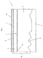
- Fig.1 shows a print carrier 1 with a foamed, recyclable pad 2, a plastic film 3 and a printing layer 4. It is presently arranged on an uneven surface 5.
- the print carrier 1 is placed here only on the ground 5. An additional connection is not provided.
- the print carrier 1 is arranged on the substrate 5 so as to be slip-proof over the base 2. Due to the foamed, flexible design of the pad 2, the bumps 6 are compensated in the substrate 5 and the thin plastic film 3 arranged above said unevenness 6 shielded, which would otherwise lead to destruction of the plastic film 3 and the print layer 4.
- the pad 2 has for this purpose a material thickness of 1.8 mm and consists at least partially of polyvinyl chloride.
- the plastic film 3 is welded in the present case with its pad-side surface 7 with the pad 2.
- the plastic film on the underside may have a layer of a glass fiber fleece to increase the mechanical and thermal stability. It also consists in this case at least partially of polyvinyl chloride and has a material thickness of 0.2 mm.
- Both the printing layer-side surface 8 of the plastic film 3 and the plastic film-side surface 9 of the pad 2 are formed in relief to achieve a desired user-side surface roughness of 10 m in interaction with the dye amount of the print layer.
- the printing layer 4 is in the present case with 10 ml / m 2 of a UV-curable dye printed on the plastic film 3. As a result, both the desired surface roughness can be achieved and, in conjunction with the mechanical and chemical properties of the base 2 and the plastic film 3, a maximum amount of heat of 480 kJ per minute can be recorded. In the present case, the printing layer 4 forms the user-side outside 10 of the print carrier 1, which is in direct contact with the environment.
- the printing substrate described with this embodiment is thus, in contrast to known from the prior art print media, usable for a variety of possible applications in which the arrangement of technically demanding substrates and certain surface properties and a degree of thermal capacity of the print carrier are required ,
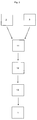
- Fig. 2 shows by way of example the production of a print carrier 1.
- the base 2 and the plastic film 3 are welded in a first step by means of pressure along their sides facing each other flat to a substrate 11.
- this compound is mechanically particularly stable, whereby a delamination of the layers 2, 3 is effectively prevented.
- the manufacturing process is simplified, since in particular can be advantageously dispensed with the use of an additional adhesive layer.
- the substrate 11 is provided in the same process step by means of pressure embossing with a regular printing layer-side relief structure.
- both the plastic film 3 and the base 2 have a relief structure.
- the differences in height of the relief structure are in this case dimensioned such that the print substrate 1 after printing of the substrate 11 has a print layer side surface roughness of at least 10 m, whereby the print substrate 1 on advantageous adhesive properties features.
- the now relief-like substrate 12 can preferably be stored on a roll or provided directly with a printing layer 4.
- the relief-like substrate 12 is fed to a conventional printer and printed with UV-curable dye.
- the UV-curable dye advantageously provides a fast drying, excellent print quality and a relatively high abrasion resistance.
- the amount of dye used here is such that a surface roughness of 10 microns and a maximum heat recordable amount of 480 kJ per minute and square meters can be achieved without taking a reduction in print quality in the present case, the UV-curable dye with a Amount of 10 ml / m 2 printed on the relief-like substrate 12.
- the printed substrate 13 is cut to form the print carrier 1 into the desired shape, in the present case rectangular.
- the print carrier can now be used.
Landscapes
- Engineering & Computer Science (AREA)
- Mechanical Engineering (AREA)
- Textile Engineering (AREA)
- Physics & Mathematics (AREA)
- General Physics & Mathematics (AREA)
- Theoretical Computer Science (AREA)
- Laminated Bodies (AREA)
Description
Die Erfindung betrifft einen Druckträger mit einer Kunststofffolie aus einer Polymerzusammensetzung, welche wenigstens teilweise Polyvinylchlorid (PVC) oder Polyolefin (PO) beinhaltet, wobei die Kunststofffolie einseitig eine Druckschicht aus wenigstens einem Farbstoff trägt.The invention relates to a print carrier with a plastic film of a polymer composition which at least partially polyvinyl chloride (PVC) or polyolefin (PO) includes, wherein the plastic film on one side carries a printing layer of at least one dye.
Gattungsgemäße Druckträger sind insbesondere in Form von Aufklebern aus dem Stand der Technik seit langem bekannt, weshalb es einem druckschriftlichen Nachweis an dieser Stelle nicht bedarf. Sie werden vorwiegend zum Bekleben von freien Flächen wie insbesondere auf Wänden, Fussböden, Möbelstücken oder dergleichen verwendet. Sie dienen dabei vorwiegend der Individualisierung der benannten Flächen und dienen insbesondere im öffentlichen Bereich als Werbeträger.Generic printing substrates are known in particular in the form of stickers from the prior art for a long time, which is why it does not require a documentary evidence at this point. They are mainly used for gluing free surfaces such as in particular on walls, floors, pieces of furniture or the like. They serve primarily to individualize the named areas and serve as advertising medium, especially in the public sector.
Diese, aus dem Stand der Technik bekannten Aufkleber haben den Nachteil, dass sie auf unebenen Flächen, wie insbesondere Kacheloberflächen, Holzvertäfelungen, Gitterflächen oder dergleichen nur bedingt oder überhaupt nicht einsetzbar sind, da sie die Form der unterliegenden Oberfläche nachbilden und so insbesondere in Kantenbereichen besagter Oberflächen das Druckmotiv in unerwünschter Weise verzerren. Darüber hinaus ist ein solcher Aufkleber in besagten Bereichen aufgrund ungleichmäßiger Krafteinwirkung besonders anfällig gegenüber Abrieb und Verschleiß. Insbesondere bei Fußbodenaufklebern führt dies nach kürzester Zeit dazu, dass diese als Werbefläche unbrauchbar werden.These known from the prior art label have the disadvantage that they are only partially or not at all used on uneven surfaces, such as tile surfaces, wood panels, grid surfaces or the like, since they replicate the shape of the underlying surface and so in particular said edge areas Surfaces distort the print motif in an undesirable manner. In addition, such a sticker is particularly susceptible to abrasion and wear in said areas due to uneven force. Especially with floor stickers this leads after a short time that they are unusable as advertising space.
Des Weiteren besteht bei solchen Aufklebern das technische Problem, dass sie nach ihrer bestimmungsgemäßen Verwendung wieder von der beklebten Oberfläche entfernt werden müssen. Aufgrund der direkten Verbindung zwischen Aufkleber und Untergrund ist das Entfernen mit großem Aufwand verbunden. Darüber hinaus werden die Aufkleber bei der Ablösung vom Untergrund in der Regel zerstört und können nicht weiterverwendet werden, was insbesondere hinsichtlich ökologischer Gesichtspunkte problematisch und angesichts des steigenden Umweltbewusstseins in der Bevölkerung nicht mehr zeitgemäß ist. Zusätzlich dazu wird der Untergrund in Mitleidenschaft gezogen, da zurückbleibende Klebereste mit aggressiven Reinigungsmitteln entfernt werden müssen. Die Lebensdauer des Untergrundes wird hierdurch in unerwünschter Weise verringert. Neben der Lebensdauer werden durch das Aufkleben eines aus dem Stand der Technik bekannten Druckträgers in Form eines Aufklebers darüber hinaus etwaige Oberflächen-, Schallschutz- und/oder Brandschutzeigenschaften des Untergrundes reduziert, was in der Folge sicherheitsrelevante Konsequenzen haben kann.Furthermore, there is a technical problem with such labels, that they according to their intended use must be removed again from the pasted surface. Due to the direct connection between sticker and substrate removal is associated with great effort. In addition, the stickers are usually destroyed during detachment from the ground and can not be reused, which is particularly problematic in terms of environmental aspects and in view of the growing environmental awareness in the population is no longer timely. In addition, the substrate is affected, since remaining adhesive residues must be removed with aggressive cleaning agents. The life of the substrate is thereby undesirably reduced. In addition to the life of any surface, sound insulation and / or fire protection properties of the substrate are reduced by sticking a known from the prior art print carrier in the form of a sticker beyond any surface, soundproofing and / or fire protection properties, which may have safety-relevant consequences in the sequence.
Ein allgemeiner Schichtaufbau ist zum Beispiel mit der
Nachteilig an dieser Ausgestaltung ist insbesondere der hohe Produktionsaufwand, eine vergleichsweise schlechte Qualität des Druckbildes, der thermischen Beständigkeit.A disadvantage of this configuration is in particular the high production costs, a comparatively poor quality of the printed image, the thermal resistance.
Die Aufgabe der Erfindung ist es daher, ausgehend vom Vorbeschriebenen einen Druckträger bereitzustellen, der die vorbeschriebenen Nachteile von gattungsgemäßen Druckträgern vermeidet.The object of the invention is therefore, starting from the above to provide a print carrier which avoids the disadvantages of generic print media described above.
Zur Lösung dieser Aufgabe schlägt die Erfindung einen gattungsgemäßen Druckträger vor, der sich dadurch auszeichnet, dass die Druckschicht versiegelungsfrei ausgebildet ist, wobei die Druckschicht die benutzerseitige Außenseite des Druckträgers bildet und, dass die Kunststofffolie mit ihrer unbedruckten Seite mit einer Unterlage stoffschlüssig verbunden ist, wobei die Unterlage eine Materialstärke von wenigstens 1,5 mm aufweist und wenigstens teilweise aus einer aufgeschäumten und recyclebaren Polymerzusammensetzung besteht, und wobei die Druckschicht mit 5 - 40 ml/m2 des wenigstens einen Farbstoffes auf die Kunststofffolie aufgedruckt ist, wobei der Druckträger insgesamt eine druckschichtseitige Oberflächenrauhigkeit von wenigstens 10 m aufweist.To solve this problem, the invention proposes a generic print carrier, which is characterized in that the print layer is formed without sealing, wherein the print layer forms the user-side outside of the print carrier and that the plastic film is bonded cohesively with its unprinted side with a substrate, said the backing has a material thickness of at least 1.5 mm and consists at least in part of a foamed and recyclable polymer composition, and wherein the print layer contains 5-40 ml / m 2 of the at least one dye is printed on the plastic film, wherein the print carrier has a total print layer-side surface roughness of at least 10 m.
Erfindungsgemäß werden die Nachteile der aus dem Stand der Technik bekannten Druckträger dadurch gelöst, dass die bedruckte Kunststofffolie nicht mehr auf Fremdoberflächen, wie insbesondere Möbelflächen, Wände und Fußböden aufgeklebt wird, sondern bereits auf einer erfindungsgemäße Unterlage angeordnet ist, wobei die mechanischen und thermischen Vorteile gegenüber herkömmlichen Aufklebern auf aus dem Stand der Technik unbekannten Synergieeffekten zwischen der Druckschicht, der Kunststofffolie und der Unterlage sowie deren technischer Ausgestaltung beruhen.According to the invention, the disadvantages of the known from the prior art print carrier is achieved in that the printed plastic film is no longer bonded to foreign surfaces, in particular furniture surfaces, walls and floors, but is already arranged on a substrate according to the invention, with the mechanical and thermal advantages Conventional labels based on unknown from the prior art synergy between the printing layer, the plastic film and the base and their technical design.
Der erfindungsgemäße Druckträger besteht hierzu aus einer Kunststofffolie, welche mit einer flexiblen und biegsamen Unterlage stoffschlüssig verbunden ist. Stoffschlüssig im Sinne der Erfindung bezeichnet hierbei insbesondere Kleben, Schweißen oder dergleichen. Vorteilhafterweise wird hierdurch eine innige Verbindung zwischen Kunststofffolie und Unterlage realisiert und eine Ablösung der Komponenten voneinander verhindert. Bei bestimmungsgemäßer Verwendung ist der Druckträger aufgrund seiner flexiblen und biegsamen Komponenten, insbesondere der Unterlage und der Kunststofffolie, in der Lage, Unebenheiten des Untergrunds, insbesondere bei Backsteinwänden, Kachelböden und dergleichen, auszugleichen. Vorteilhafterweise ist die optische Einheitlichkeit des Druckmotives damit unabhängig vom jeweiligen Untergrund stets gewährleistet. Die erfindungsgemäße Unterlage vermag darüber hinaus druckschichtseitige mechanische Belastungen abzufedern und sorgt so trotz etwaiger Unebenheiten des Untergrunds für eine gleichmäßige Kraftaufnahme und reduziert auf diese Weise Abrieb und Verschleiß der Druckschicht. Vorteilhafterweise wird der bestimmungsgemäße Gebrauch des Druckträgers als Werbeträger somit im Gegensatz zu aus dem Stand der Technik bekannten Druckträgern nicht durch den Untergrund und/oder mechanische Einwirkung beeinträchtigt. Erfindungsgemäß weist die Unterlage hierfür eine Materialstärke von wenigstens 1,5 mm auf. Bevorzugt ist eine Materialstärke von 1,5 - 5 mm, weiter bevorzugt 1,6 - 3 mm, noch weiter bevorzugt 1,6 - 2,0 mm und besonders bevorzugt 1,8 mm. Es hat sich gezeigt, dass eine solche Materialstärke einen optimierten Kompromiss zwischen Flexibilität, Gewicht und Kraft- und Wärmeaufnahmekapazität bietet. Die damit erreichbare Flexibilität ermöglicht insbesondere die Lagerung der Unterlage und/oder des Druckträgers als Rollenware, vorzugsweise in den Maßen 4 m x 30 m. Hierdurch wird eine kontinuierliche Bedruckung des Substrates ermöglicht und die Produktion hinsichtlich ihrer Effizienz optimiert.For this purpose, the print carrier according to the invention consists of a plastic film, which is bonded cohesively to a flexible and flexible base. Cohesive in the sense of the invention in this case denotes in particular gluing, welding or the like. Advantageously, an intimate connection between the plastic film and the base is thereby realized and a detachment of the components from each other is prevented. When used as intended, the print carrier is due to its flexible and flexible components, in particular the pad and the plastic film, able to compensate for unevenness of the substrate, especially in brick walls, tile floors and the like. Advantageously, the optical uniformity of the printing motif is thus always guaranteed independently of the respective background. The pad according to the invention is also able to absorb compressive layer-side mechanical loads and thus ensures despite any unevenness of the ground for a uniform power and thus reduces abrasion and wear of the print layer. Advantageously, the intended use of the print carrier as an advertising medium thus, in contrast to known from the prior art print media is not affected by the background and / or mechanical action. According to the invention, the base for this purpose has a material thickness of at least 1.5 mm. Preferred is a material thickness of 1.5-5 mm, more preferably 1.6-3 mm, even more preferably 1.6-2.0 mm and particularly preferably 1.8 mm. It has been found that such a material thickness offers an optimized compromise between flexibility, weight and power and heat absorption capacity. The flexibility achievable thereby makes it possible, in particular, to mount the underlay and / or the print carrier as a roll product, preferably in the
Der erfindungsgemäße Druckträger ist darüber hinaus wiederverwendbar, da er zur ortsfesten Anordnung nicht mit dem Untergrund verklebt werden muss, sondern durch die geschäumte Ausgestaltung der Unterlage in Verbindung mit ihrer erfindungsgemäßen Zusammensetzung für eine verrutschsichere Anordnung des Druckträgers zumindest auf ebenen und schrägen Oberflächen sorgt. Vorteilhafterweise wird damit eine Zerstörung des Druckträgers und eine Beschädigung des Untergrundes vollständig vermieden. Für die Anordnung des Druckträgers an im Wesentlichen vertikalen Flächen weist der Druckträger vorzugsweise geeignete Haltemittel zur hängenden Anordnung auf. Alternativ, kann der Druckträger wie auch im Stand der Technik mit dem Untergrund verklebt werden, wodurch eine besonders einfache und stabile Verbindung mit der vertikalen Fläche ausgebildet wird. Auch gemäß dieser alternativen Befestigungsmethode erbringt der Druckträger weiterhin die erfindungsgemäßen Vorteile hinsichtlich des Ausgleichs von Unebenheiten des Untergrunds.The print carrier according to the invention is also reusable, since it does not have to be bonded to the substrate for stationary arrangement, but at least on flat and oblique surfaces by the foamed design of the pad in conjunction with its composition of the invention for a slip-resistant arrangement of the print carrier. Advantageously, a destruction of the print carrier and damage to the substrate is thus completely avoided. For the arrangement of the print carrier on substantially vertical surfaces, the print carrier preferably has suitable holding means for hanging arrangement. Alternatively, the print carrier can be glued to the substrate as in the prior art, whereby a particularly simple and stable connection with the vertical surface is formed. Also, according to this alternative attachment method, the print carrier continues to provide the advantages of the invention in terms of the compensation of unevenness of the ground.
Erfindungsgemäß besteht die Unterlage aus einer recyclebaren Polymerzusammensetzung. Vorzugsweise werden hierzu im Wesentlichen ausschließlich recyclebare Komponenten, wie insbesondere, Polyvinylchlorid, Polystyrol, Polyolefine und dergleichen verwendet. Des Weiteren können der recyclebaren Zusammensetzung Additive, Weichmacher, Pigmente, Füllstoffe, insbesondere Faserfüllstoffe, und Stabilisatoren enthalten. Die erfindungsgemäße Unterlage ist daher dem Wiederverwertungszyklus zuführbar und kann ressourcenschonend produziert werden. Besonders bevorzugt besteht die Unterlage aus biologisch abbaubaren Kunststoffen, insbesondere auf Stärke-, Milchsäure, Cellulose- oder Polyhydroxyalkanoatbasis, insbesondere Polyhydroxybuttersäure. Über die verwendeten biologisch abbaubaren Kunststoffe kann vorzugsweise eine Mindestverwendungsdauer eingestellt und anschließend umweltverträglich entsorgt werden. Insbesondere bei Druckmotiven mit zeitlicher begrenzter Gültigkeit, wie insbesondere Werbeaktionen, ist dies hinsichtlich der großen Zahl an anfallenden Abfallstoffen nach der bestimmungsgemäßen Verwendung in hohem Maße vorteilhaft.According to the invention, the pad consists of a recyclable polymer composition. For this purpose, essentially exclusively recyclable components, such as in particular, polyvinyl chloride, polystyrene, polyolefins and the like are preferably used for this purpose. Furthermore, the recyclable composition may contain additives, plasticizers, pigments, fillers, especially fiber fillers, and stabilizers. The pad according to the invention can therefore be fed to the recycling cycle and can be produced in a resource-saving manner. Particularly preferably, the pad consists of biodegradable plastics, in particular starch, lactic acid, cellulose or Polyhydroxyalkanoatbasis, in particular polyhydroxybutyric acid. About the biodegradable plastics used can preferably be set a minimum period of use and then disposed of environmentally friendly. In particular, in the case of print motifs with limited validity, in particular advertising campaigns, this is highly advantageous in view of the large number of waste materials produced after the intended use.
Erfindungsgemäß ist die Kunststofffolie aus einer Polymerzusammensetzung gebildet, welche wenigstens teilweise Polyvinylchlorid, Polyolefin oder bevorzugt Polyolefin-Copolymeren beinhaltet. Die Kunststofffolie ist hierdurch mechanisch ausgesprochen stabil, widerstandsfähig gegenüber Abrieb und ebenfalls recyclebar. Darüber hinaus eignet sie sich optimal als Substrat zu Aufnahme der Druckschicht, da zwischen dem erfindungsgemäß Farbstoff und den vorgenannten Materialien eine abriebsbeständige Wechselwirkung besteht. Die Druckschicht ist somit über die Kunststofffolie wenigstens zum Teil vor Abrieb geschützt. Bevorzugterweise weist die Kunststofffolie eine Materialstärke von 0,1 - 0,4 mm, vorzugsweise 0,2 mm, auf. Insbesondere in Kombination mit der Materialstärke der Unterlage ergibt sich ein besonders flexibler, mechanisch stabiler Druckträger, der in einfacher Weise hochqualitativ bedruckt werden kann.According to the invention, the plastic film is formed from a polymer composition which at least partially comprises polyvinyl chloride, polyolefin or, preferably, polyolefin copolymers includes. The plastic film is thus mechanically extremely stable, resistant to abrasion and also recyclable. In addition, it is optimally suitable as a substrate for receiving the printing layer, since there is an abrasion-resistant interaction between the dye according to the invention and the abovementioned materials. The print layer is thus at least partially protected against abrasion via the plastic film. The plastic film preferably has a material thickness of 0.1-0.4 mm, preferably 0.2 mm. In particular, in combination with the material thickness of the pad results in a particularly flexible, mechanically stable print carrier, which can be printed in high quality in a simple manner.
Gemäß einer bevorzugten Ausgestaltung der Erfindung ist die Kunststofffolie zweischichtig aufgebaut und verfügt unterlagenseitig über eine Faserschicht, insbesondere einem Glasfaservlies zur vorteilhaften Erhöhung der Stabilität des Druckträgers. Insbesondere bei einer Verwendung auf Fußböden, bei der große Kräfte auf den Druckträger einwirken ist eine solche Ausgestaltung besonders vorteilhaft. Darüber hinaus erhöht die Faserschicht durch Verringerung des Wärmeausdehnungskoeffizienten des Druckträgers in vorteilhafter Weise die Formsteifigkeit des Druckträgers bei Temperaturschwankungen, was insbesondere bei Anwendungen außerhalb von geschlossenen Räumen von großem Vorteil ist.According to a preferred embodiment of the invention, the plastic film is constructed in two layers and on the pad side has a fiber layer, in particular a glass fiber fleece for advantageous increase in the stability of the print carrier. In particular, when used on floors, act in the large forces on the print carrier such a configuration is particularly advantageous. In addition, by reducing the coefficient of thermal expansion of the print carrier, the fiber layer advantageously increases the stiffness of the print carrier in the event of temperature fluctuations, which is particularly advantageous in applications outside of closed spaces.
Erfindungsgemäß weist der Druckträger eine druckschichtseitige Oberflächenrauhigkeit von wenigstens 10 m, vorzugsweise 10 - 30 m, weiter bevorzugt 13 - 20 m auf. Oberflächenrauhigkeit im Sinne der Erfindung bezeichnet die Distanz zwischen der gemittelten maximalen Höhe und der gemittelten minimalen Höhe der Oberfläche. Vorteilhafterweise weist der Druckträger durch die erfindungsgemäße Oberflächenrauhigkeit vergleichsweise gute Hafteigenschaften auf, welche unter anderem bei der Begehung des Druckträgers insbesondere bei der Verwendung als Bodenbelag, bei der Anordnung von Gegenständen auf dem Druckträger insbesondere bei der Verwendung als Tischauflage oder bei der sensorischen Abtastung des Druckträgers insbesondere bei der Verwendung als Mouse-Pad vorteilhaft ist. Die Oberflächenrauhigkeit sorgt diesbezüglich für eine verbesserte Rutschsicherheit bei der Begehung und/oder der Ablage von Gegenständen auf dem Druckträger. Insbesondere ist damit eine Rutschsicherheit auf trockenen, wassernassen, wasserfeuchten und öligen bzw. fettigen Druckträgern gegeben. Dies ist insbesondere dort von Vorteil, wo die Gefahr einer Oberflächenbenetzung mit Wasser oder anderen Flüssigkeiten, wie insbesondere Öl, besteht. So kann es z.B. in einem Restaurant, im welchen ein erfindungsgemäßer Druckträger als Tischauflage verwendet wird, passieren, dass Getränke verschüttet werden und den Druckträger benetzen. Durch die erfindungsgemäße Oberflächenrauhigkeit ist auch bei einer solchen Benetzung eine vorteilhafte Rutschsicherheit des Druckträgers gegeben, wodurch insbesondere Gläser und dergleichen verrutschsicher auf diesem platziert werden können. Darüber hinaus sorgt die Oberflächenrauhigkeit für eine verbesserte Sensorgenauigkeit bei der Verwendung als Mouse-Pad, welche auf die vergleichsweise große abtastbare Oberfläche des Druckträgers zurückzuführen ist. Vorzugsweise wird die Oberflächenrauhigkeit dadurch realisiert, dass die Kunststofffolie und/oder die Unterlage druckschichtseitig reliefartig ausgebildet sind. Reliefartig im Sinne der Erfindung bedeutet, dass die jeweilige Oberfläche regelmäßig oder unregelmäßig angeordnete Erhöhungen und Vertiefungen aufweist, welche hinsichtlich ihrer Höhendifferenz derart ausgebildet sind, dass der Druckträger auch nach dem Bedrucken der Kunststofffolie mit der Druckschicht noch die vorgenannte Oberflächenrauhigkeit aufweist.According to the invention, the print carrier has a print layer-side surface roughness of at least 10 m, preferably 10 to 30 m, more preferably 13 to 20 m. Surface roughness in the sense of the invention denotes the distance between the averaged maximum height and the averaged minimum height of the surface. Advantageously, the print carrier by the surface roughness according to the invention comparatively good adhesive properties, which, inter alia, when inspecting the print carrier in particular when used as a floor covering, in the arrangement of objects on the print carrier in particular when used as a table top or in the sensory scanning of the print carrier advantageous when used as a mouse pad. The surface roughness in this respect ensures improved slip resistance during the inspection and / or storage of objects on the print carrier. In particular, this provides slip resistance on dry, water-wet, water-moist and oily or greasy print media. This is particularly advantageous where the risk of surface wetting with water or other liquids, in particular Oil exists. Thus, for example, in a restaurant in which an inventive print carrier is used as a table top, it happens that drinks are spilled and wet the print carrier. Due to the surface roughness according to the invention, even with such wetting an advantageous slip resistance of the print carrier is given, whereby in particular glasses and the like can be placed on this slip-proof. In addition, the surface roughness provides improved sensor accuracy when used as a mouse pad due to the relatively large scannable surface of the print carrier. Preferably, the surface roughness is realized in that the plastic film and / or the base pressure-layer side are designed in relief. Relief-like in the sense of the invention means that the respective surface has regularly or irregularly arranged elevations and depressions, which are designed in terms of their height difference such that the print carrier still has the aforementioned surface roughness after printing the plastic film with the print layer.
Erfindungsgemäß wird die Druckschicht mit einer Farbstoffmenge von 5 - 40 ml/m2, vorzugsweise 10 - 30 ml/m2 und weiter bevorzugt 15 - 20 ml/m2, aufgedruckt. Es hat sich gezeigt, dass eine solche Farbstoffmenge insbesondere in Verbindung mit der reliefartigen Ausgestaltung der Kunststofffolie zu der angestrebten Oberflächenrauhigkeit führt, ohne dabei die Bildqualität des abgedruckten Motives zu beinträchtigen. Generell sind verschiedene Druckverfahren mit unterschiedlichen Farbstoffarten zur Bedruckung der Kunststofffolie geeignet. Erfindungsgemäß besteht die Druckschicht aus wenigstens einem Farbstoff. Bei insbesondere S/W-Motiven ist die Verwendung eines einzigen Farbstoffes ausreichend, wodurch die Herstellung des Druckträgers vereinfacht ist. Bei insbesondere farbigen Motiven ist es jedoch bevorzugt, die Druckschicht aus einem Farbstoffsystem aus 4 Farbstoffen, insbesondere blau, purpur, gelb und schwarz, auch bekannt als CMYK (Cyan, Magenta, Yellow, Key) - System auszubilden. Vorzugsweise kann das CMYK-System, zur Verbesserung des Druckbildes durch zwei weitere Farben, insbesondere orange und grün ergänzt werden. Bevorzugt ist der wenigstens eine Farbstoff oder das jeweilige Farbstoffsystem aus wenigstens einem UV-härtbaren Farbstoff gebildet, der vorteilhafterweise eine schnelle Aushärtung, eine hervorragende Druckqualität und eine vergleichsweise gute Abriebsbeständigkeit bietet.According to the invention, the printing layer is printed with a dye quantity of 5 to 40 ml / m 2 , preferably 10 to 30 ml / m 2 and more preferably 15 to 20 ml / m 2 . It has been found that such an amount of dye, especially in conjunction with the relief-like configuration of the plastic film, leads to the desired surface roughness, without impairing the image quality of the printed motif. In general, various printing methods with different types of dyes are suitable for printing on the plastic film. According to the invention, the print layer consists of at least one dye. In particular black and white subjects, the use of a single dye is sufficient, whereby the production of the print carrier is simplified. In the case of especially colored motifs, however, it is preferred to form the printing layer from a dye system comprising 4 dyes, in particular blue, purple, yellow and black, also known as CMYK (cyan, magenta, yellow, key) system. Preferably, the CMYK system can be supplemented to improve the printed image by two other colors, in particular orange and green. The at least one dye or the respective dye system is preferably formed from at least one UV-curable dye, which advantageously offers rapid curing, outstanding print quality and comparatively good abrasion resistance.
Zusätzlich zu den vorgenannten Auswirkungen auf die Oberflächenrauhigkeit ist die Menge des verwendeten Farbstoffes hinsichtlich der thermischen Eigenschaften, insbesondere der Entzündlichkeit, des Druckträgers von höchster Relevanz. Es hat sich gezeigt, dass eine Farbstoffmenge von 5 - 40 ml, vorzugsweise 10 - 30 ml, weiter bevorzugt 15 - 20 ml pro Quadratmeter neben der vorgenannten Vorteile darüber hinaus in Verbindung mit den thermischen Eigenschaften der unteren Schichten für eine verminderte Entzündlichkeit des Druckträgers im Vergleich zum Stand der Technik beiträgt. Vorzugsweis kann der Druckträger somit eine maximale Wärmemenge von wenigstens 270 kJ, weiter bevorzugt wenigstens 480 kJ in der Minute und pro Quadratmeter aufnehmen ohne sich zu entzünden. Dies ist insbesondere dort vorteilhaft, wo der Druckträger übermäßiger thermischer Belastung ausgesetzt ist. Er leistet damit im Gegensatz zu aus dem Stand der Technik bekannten Druckträgern einen positiven Beitrag zum Brandschutz und zur Wärmedämmung und kann dementsprechend in Bereichen verwendet werden, die gattungsgemäßen Druckträgern verwehrt sind. Insbesondere eine maximal aufnehmbare Wärmemenge von 480 kJ pro Quadratmeter und Minute gestattet die Verwendung des Druckträgers in Bereichen mit hoher thermischer Belastung wie insbesondere auf sich bei intensiver Sonneneinstrahlung stark erhitzenden Untergründen, wie insbesondere Asphalt, Metall oder dergleichen.In addition to the above effects on the surface roughness, the Amount of the dye used with regard to the thermal properties, in particular the flammability, of the print carrier of the highest relevance. It has been shown that a dye amount of 5 - 40 ml, preferably 10 - 30 ml, more preferably 15 - 20 ml per square meter in addition to the aforementioned advantages beyond in conjunction with the thermal properties of the lower layers for a reduced flammability of the print carrier in Comparison with the prior art contributes. Preferably, the printing medium can thus receive a maximum amount of heat of at least 270 kJ, more preferably at least 480 kJ per minute and per square meter without igniting. This is particularly advantageous where the print carrier is exposed to excessive thermal stress. He thus makes in contrast to known from the prior art print media a positive contribution to fire protection and thermal insulation and can be used accordingly in areas that are denied generic printing media. In particular, a maximum amount of heat absorbable 480 kJ per square meter and minute allows the use of the print carrier in areas with high thermal stress as in particular on strongly heated in intense sunlight, such as asphalt, metal or the like.
Gemäß der Erfindung bildet die Druckschicht die benutzerseitige Außenseite des Druckträgers. Auf eine Versiegelung der Druckschicht wird explizit verzichtet, da es sich gezeigt hat, dass eine solche Versiegelung hinsichtlich der Darstellung des Druckbildes, der Recyclefähigkeit, des Produktionsaufwands und mechanischen und thermischen Eigenschaften des erfindungsgemäßen Druckträgers nachteilig ist.According to the invention, the print layer forms the user-side outside of the print carrier. Sealing of the printing layer is explicitly dispensed with, since it has been shown that such a seal is disadvantageous with regard to the representation of the printed image, the recyclability, the production effort and the mechanical and thermal properties of the print carrier according to the invention.
Neben den vorgenannten Vorteilen gestatten die erfindungsgemäßen Einzelkomponenten eine vergleichsweise einfache, kostengünstige und hochgradig individualisierbare Herstellung des erfindungsgemäßen Druckträgers.In addition to the abovementioned advantages, the individual components according to the invention permit a comparatively simple, inexpensive and highly customizable production of the print carrier according to the invention.
So ist es bevorzugterweise vorgesehen, dass die Unterlage und die Kunststofffolie in separaten Verfahren hergestellt und als späteres Substrat nach Art eines Zwischenprodukts ohne Verlust der Materialqualität zwischengelagert werden kann. Die Unterlage und die Kunststofffolie werden bevorzugt stoffschlüssig, insbesondere durch Kleben oder Schweißen, miteinander verbunden. Das daraus entstehende Zwischenprodukt bildet ein Substrat, welches in einfacher Weise gelagert und bedruckt werden kann. Vorzugsweise wird das vorgefertigte Substrat nach Eingang der Kundenbestellung zum erfindungsgemäßen Druckträger ausgebildet, indem es mit dem gewünschten Motiv bedruckt wird. Hierdurch ist es möglich, individuellen Kundenwünschen in einfacher Weise Rechnung zu tragen.Thus, it is preferably provided that the base and the plastic film can be produced in separate processes and stored as a later substrate in the manner of an intermediate product without loss of material quality. The base and the plastic film are preferably bonded together, in particular by gluing or welding. The resulting intermediate product forms a substrate which can be stored and printed in a simple manner. Preferably, the prefabricated substrate after receipt of the Customer order designed to print carrier according to the invention by being printed with the desired motif. This makes it possible to easily accommodate individual customer requests.
Gemäß einer bevorzugten Ausgestaltung der Erfindung werden die Kunststofffolie. und/oder die Unterlage zur Ausbildung einer druckschichtseitigen Oberflächenrauhigkeit während des Zusammenfügens zum Substrat in Reliefform gebracht. Vorzugsweise wird die Reliefstruktur der Kunststofffolie und/oder der Unterlage mittels Druckprägung mit einer geeigneten Druckform eingebracht und beide gleichzeitig zum Substrat druckverschweißt. Das Substrat kann hierdurch an jede gewünschte Oberflächenrauhigkeit individuell angepasst werden. Darüber hinaus können durch diese Methode, sofern gewünscht, sowohl die Kunststofffolie als auch die Unterlage in einem gemeinsamen Arbeitsschritt in Reliefform gebracht werden, womit die Herstellung des Druckträgers insgesamt vereinfacht wird. Alternativ dazu kann die gewünschte Oberflächenrauhigkeit auch nach dem Zusammenfügen zum Substrat durch mechanischer Anrauhung mittels Abrieb oder dergleichen realisiert werden.According to a preferred embodiment of the invention, the plastic film. and / or the substrate for forming a pressure-layer-side surface roughness during assembly to the substrate in relief form. Preferably, the relief structure of the plastic film and / or the base is introduced by means of pressure embossing with a suitable printing forme and both simultaneously pressure-welded to the substrate. The substrate can thereby be individually adapted to any desired surface roughness. In addition, by this method, if desired, both the plastic film and the base are brought in a joint step in relief form, whereby the production of the print carrier is simplified as a whole. Alternatively, the desired surface roughness can also be realized after assembly to the substrate by mechanical roughening by means of abrasion or the like.
Bevorzugt ist es, das Substrat auf einer Rolle zu lagern und auf die individuellen dimensionalen Erfordernisse hin zurechtzuschneiden. Ein etwaiger Verschnitt kann vorteilhafterweise dadurch minimiert werden, dass große Motive für insbesondere Boden oder Wandgrafiken mosaikartig auf beliebig kleine Druckträger verteilt und zu einem Gesamtmotiv zusammengefügt werden. Sollte dennoch ein gewisser Verschnitt anfallen, so kann eine etwaige daraus resultierende Materialverschwendung durch die vielseitige Nutzbarkeit des Druckträgers minimiert werden. So ist es insbesondere möglich, Verschnitt der bei einer ersten Bestellung von z.B. großflächigen Wandgrafiken, für eine nachfolgende Bestellung von z.B. kleinflächigen Mouse-Pads zu verwenden. Auf diese Weise ist es möglich einen erfindungsgemäßen Druckträger, ohne Materialverschwendung und entsprechend geringen Kosten zu produzieren. Etwaige dennoch auftretende Verschnittreste können, aufgrund ihrer Recyclefähigkeit wieder dem Materialkreislauf zugeführt werden, wodurch eine Umweltbelastung vollends minimiert wird.It is preferable to store the substrate on a roll and cut it to the individual dimensional requirements. A possible waste can be advantageously minimized by large motifs for particular floor or wall graphics mosaic-like distributed on any small print carrier and assembled into a total motif. Nevertheless, should a certain amount of waste be generated, any resulting waste of material can be minimized by the versatile usability of the print carrier. Thus, it is possible, in particular, to make offcuts in the case of a first order of e.g. large-scale wall graphics, for a subsequent order of e.g. to use small-area mouse pads. In this way it is possible to produce a print carrier according to the invention, without waste of material and correspondingly low costs. Any still occurring Verschnittreste can be fed back to the material cycle due to their recyclability, whereby an environmental impact is completely minimized.
Gemäß einer alternativen Ausgestaltung der Erfindung wird das Substrat bedruckt und der resultierende Druckträger anschließend in die gewünschte Form zugeschnitten. Dies ist insbesondere bei großflächigen Motiven von Vorteil, da dieses kontinuierlich gedruckt werden kann, ohne die Substrate tauschen zu müssen, wodurch die Herstellung vorteilhafterweise vereinfacht wird.According to an alternative embodiment of the invention, the substrate is printed and then cut the resulting print carrier in the desired shape. This is particularly advantageous for large-scale subjects, as this printed continuously can be without having to exchange the substrates, whereby the production is advantageously simplified.
Gemäß einer bevorzugten Ausgestaltung der Erfindung können das Substrat oder der Druckträger in jede gewünschte Form zugeschnitten werden, so dass der Druckträger im Resultat hinsichtlich seiner Form individualisierbar ausgebildet ist. Vorzugsweise können Substrat oder Druckträger in rechteckiger, runder oder individuell frei gestalteter Form zugeschnitten werden. Hierdurch ist es möglich, die Wirkung des auf dem Druckträger befindlichen Motives durch eine korrespondierende Formgebung zu verstärken. Hierbei sind Formen jeder Art, insbesondere in Form von stilisierten Tieren, Sportgeräten, Lebensmitteln und dergleichen denkbar.According to a preferred embodiment of the invention, the substrate or the print carrier can be cut into any desired shape, so that the print carrier is formed in the result customizable in terms of its shape. Preferably, substrate or print substrate can be cut in rectangular, round or individually freely designed form. This makes it possible to enhance the effect of the motif located on the print carrier by a corresponding shaping. Here, forms of any kind, especially in the form of stylized animals, sports equipment, food and the like are conceivable.
Gemäß einem bevorzugten Merkmal der Erfindung wird das zusammengefügte und in Reliefform gebrachte Substrat einer Druckvorrichtung zugeführt und mit einer vorgegeben Menge an Farbstoff pro Quadratmeter bedruckt. Vorzugsweise kann hierbei in einfacher Weise ein herkömmliches Druckgerät zur Bedruckung von Kunststofffolien verwendet werden. Die Notwendigkeit eines speziellen Druckgerätes entfällt somit, wodurch die Produktion des Druckträgers insgesamt weiter vereinfacht ist. Das Substrat ist erfindungsgemäß mit jedem gewünschten Motiv in jeder gewünschten Farbkombination bedruckbar. Die sich hieraus ergebenden Möglichkeiten sind vielfältig. Insbesondere sind die abgebildeten Motive in ihrer Flächenerstreckung problemlos skalierbar. Dies wird insbesondere dadurch erreicht, dass eine gewünschte Zahl von Substraten mit Teilen des Gesamtmotives bedruckt und am Verwendungsort zum Gesamtmotiv zusammengesetzt werden. Auf diese Weise lassen sich auch vergleichsweise große Flächen insbesondere zu Werbezwecken einheitlich nutzen. Insbesondere bei der werbewirksamen Ausgestaltung von Böden und Wänden von Messehallen, Einkaufzentren und dergleichen besteht in dieser Hinsicht großer Bedarf. Darüber hinaus können auch vergleichsweise klein bemessene Substrate mit insbesondere Einzelmotiven, wie insbesondere persönlichen Fotos, künstlerischen Motiven und dergleichen, bedruckt werden. Vorteilhafterweise lassen sich auf diese Art insbesondere Mouse-Pads, Tischauflagen, Bodenschutzmatten für insbesondere Schreibtischstühle und Sportgeräte sowie Dartscheiben und Tresenauflagen für Autohäuser, Tankstellen und dergleichen individuell auf den jeweiligen Kundenwunsch abgestimmt herstellen. Durch die freie Skalierbarkeit des Druckträgers kann darüber hinaus ein etwaiger Materialverlust beim Zuschneiden weitgehend minimiert werden.According to a preferred feature of the invention, the assembled and in relief form substrate is fed to a printing device and printed with a predetermined amount of dye per square meter. Preferably, in this case, a conventional printing device for printing on plastic films can be used in a simple manner. The need for a special printing device is thus eliminated, whereby the production of the print carrier is simplified on the whole further. The substrate according to the invention can be printed with any desired motif in any desired color combination. The resulting possibilities are manifold. In particular, the imaged motifs are easily scalable in their areal extent. This is achieved in particular by printing a desired number of substrates with parts of the overall motif and assembling them at the point of use to form the overall motif. In this way, even comparatively large areas can be used uniformly, in particular for advertising purposes. Especially in the promotional effective design of floors and walls of exhibition halls, shopping centers and the like, there is great need in this regard. In addition, even comparatively small substrates with particular single motifs, such as in particular personal photos, artistic motifs and the like, can be printed. Advantageously, in this way, in particular mouse pads, table supports, floor mats for particular desk chairs and sports equipment and dartboards and counter pads for car dealerships, gas stations and the like can be tailored to the particular customer request produced. In addition, due to the free scalability of the print carrier, any material loss during cutting can be largely minimized.
Sämtliche erfindungsgemäßen und bevorzugten Merkmale sorgen in synergetischer Weise für die Bereitstellung eines Druckträgers, dessen Anwendungsbereich unabhängig vom Untergrund ist, der recyclebar ist und der vergleichsweise vorteilhafte thermische Eigenschaften und vorteilhafte benutzerseitige Oberflächenrauhigkeit besitzt. Solche Druckträger eignen sich insbesondere bei der Verwendung als Tischauflage, Mouse-Pad, Wandbehang, Bodenmatte und dergleichen für Werbezwecke oder auch zum Erstellen großflächiger und individueller Wand- oder Bodenmotive.All of the inventive and preferred features provide synergistically for the provision of a print carrier whose application is independent of the substrate, which is recyclable and which has comparatively advantageous thermal properties and advantageous user-side surface roughness. Such print media are particularly suitable for use as a table top, mouse pad, wall hanging, floor mat and the like for promotional purposes or to create large-scale and individual wall or floor designs.
Die folgenden Ausführungsbeispiele dienen lediglich der Erläuterung und sind in keiner Weise beschränkend zu verstehen.
-
Fig.1 zeigt in skizzenhafter, nicht maßstabsgetreuer Schnittdarstellung einen erfindungsgemäßen Druckträger; -
Fig. 2 zeigt in schematischer Darstellung eine bevorzugte Verfahrensführung zur Herstellung des erfindungsgemäßen Druckträgers.
-
Fig.1 shows in sketchy, not true to scale sectional view of a print carrier according to the invention; -
Fig. 2 shows a schematic representation of a preferred process control for the preparation of the print carrier according to the invention.
Der Druckträger 1 ist hierbei lediglich auf den Untergrund 5 aufgelegt. Eine darüber hinausgehende Verbindung ist nicht vorgesehen. Der Druckträger 1 ist über die Unterlage 2 verrutschsicher auf dem Untergrund 5 angeordnet. Durch die aufgeschäumte, flexible Ausgestaltung der Unterlage 2 werden die Unebenheiten 6 im Untergrund 5 ausgeglichen und die darüber angeordnete dünne Kunststofffolie 3 von besagten Unebenheiten 6 abgeschirmt, welche anderenfalls zu einer Zerstörung der Kunststofffolie 3 und der Druckschicht 4 führen würden. Die Unterlage 2 weist hierzu eine Materialstärke von 1,8 mm auf und besteht wenigstens teilweise aus Polyvinylchlorid.The
Die Kunststofffolie 3 ist vorliegend mit ihrer unterlagenseitigen Oberfläche 7 mit der Unterlage 2 verschweißt. Ergänzend kann die Kunststofffolie gemäß einer optionalen Ausgestaltung unterlagenseitig über eine Schicht aus einem Glasfaservlies zur Erhöhung der mechanischen und thermischen Stabilität verfügen. Sie besteht vorliegend ebenfalls wenigstens teilweise aus Polyvinylchlorid und weist eine Materialstärke von 0,2 mm auf.The
Sowohl die druckschichtseitige Oberfläche 8 der Kunststofffolie 3 als auch die kunststofffolienseitige Oberfläche 9 der Unterlage 2 sind reliefartig ausgebildet um im Zusammenspiel mit der Farbstoffmenge der Druckschicht eine gewünschte benutzerseitige Oberflächenrauhigkeit von 10 m zu erreichen.Both the printing layer-
Die Druckschicht 4 ist vorliegend mit 10 ml/m2 eines UV-härtbaren Farbstoffes auf die Kunststofffolie 3 aufgedruckt. Hierdurch kann sowohl die gewünschte Oberflächenrauhigkeit erreicht, als auch, in Verbindung mit den mechanischen und chemischen Eigenschaften der Unterlage 2 und der Kunststofffolie 3, eine maximale Wärmemenge von 480 kJ in der Minute aufgenommen werden. Die Druckschicht 4 bildet vorliegend die benutzerseitige Außenseite 10 des Druckträgers 1, welche direkt mit der Umgebung in Kontakt steht.The
Der mit diesem Ausführungsbeispiel beschriebene Druckträger ist damit, im Gegensatz zu aus dem Stand der Technik bekannten Druckträgern, für eine Vielzahl von möglichen Anwendungen verwendbar, in denen die Anordnung auf technisch anspruchsvollen Untergründen sowie bestimmte Oberflächeneigenschaften und ein gewisses Maß an thermischer Aufnahmefähigkeit des Druckträgers erforderlich sind.The printing substrate described with this embodiment is thus, in contrast to known from the prior art print media, usable for a variety of possible applications in which the arrangement of technically demanding substrates and certain surface properties and a degree of thermal capacity of the print carrier are required ,
Ausgangsprodukte bilden hierbei die auf einer Rolle gelagerte Kunststofffolie 3 und die auf einer Rolle gelagerte Unterlage 2. Die Unterlage 2 und die Kunststofffolie 3 werden in einem ersten Schritt mittels Druck entlang ihrer einander zugewandten Seiten flächig zu einem Substrat 11 verschweißt. Vorteilhafterweise ist diese Verbindung mechanisch besonders stabil, wodurch eine Delamination der Schichten 2, 3 wirkungsvoll unterbunden ist. Darüber hinaus ist der Herstellungsprozess vereinfacht, da insbesondere auf den Einsatz einer zusätzlichen Klebstoffschicht vorteilhafterweise verzichtet werden kann.The
Das Substrat 11 wird in demselben Verfahrensschritt mittels Druckprägung mit einer regelmäßigen druckschichtseitigen Reliefstruktur versehen. Infolgedessen weisen sowohl die Kunststofffolie 3 und die Unterlage 2 eine Reliefstruktur auf. Die Höhenunterschiede der Reliefstruktur sind hierbei derart bemessen, dass der Druckträger 1 nach der Bedruckung des Substrats 11 eine druckschichtseitige Oberflächenrauhigkeit von wenigstens 10 m aufweist, wodurch der Druckträger 1 über vorteilhafte HaftEigenschaften verfügt.The
Nach der Druckprägung kann das nunmehr reliefartige Substrat 12 vorzugsweise auf einer Rolle zwischengelagert oder direkt mit einer Druckschicht 4 versehen werden. Hierzu wird das reliefartige Substrat 12 einem herkömmlichen Drucker zugeführt und mit UV-härtbarem Farbstoff bedruckt. Der UV-härtbare Farbstoff sorgt vorteilhafterweise für eine schnelle Trocknung, exzellente Druckqualität und eine vergleichsweise hohe Abriebbeständigkeit. Die Menge des verwendeten Farbstoffes ist hierbei derart bemessen, dass eine Oberflächenrauhigkeit von 10 µm und eine maximal aufnehmbare Wärmemenge von 480 kJ pro Minute und Quadratmeter erreicht werden, ohne eine Verminderung der Druckqualität in Kauf zu nehmen, Vorliegend wird der UV-härtbare Farbstoff mit einer Menge von 10 ml/m2 auf das reliefartige Substrat 12 aufgedruckt.After the pressure embossing, the now relief-
Nach der Bedruckung und einer anschließenden Trocknung wird das bedruckte Substrat 13 zur Ausbildung des Druckträgers 1 in die gewünschte Form zugeschnitten, vorliegend rechteckig, zugeschnitten. Der Druckträger ist nun einsetzbar.After printing and subsequent drying, the printed
Claims (10)
- A print substrate comprising a plastic foil consisting of a polymer composition which at least partially contains polyvinyl chloride (PVC) or polyolefin (PO), wherein the plastic foil carries a print layer consisting of at least one dye on one side, characterized in that the print layer is seal-free, wherein the print layer forms the outer side of the print substrate with respect to the user, and that the unprinted side of the plastic foil is firmly bonded to an underlay, wherein the underlay comprises a material thickness of at least 1.5 mm and consists at least partially of a foamed and recyclable polymer composition, and wherein the print layer is printed onto the plastic foil with 5 - 40 ml/m2 of the at least one dye, wherein the print substrate altogether comprises a surface roughness of at least 10 µm on the side of the print layer.
- A print substrate according to claim 1, characterized in that the underlay comprises a material thickness comprised between 1.6 mm and 2.0 mm.
- A print substrate according to claim 1 or 2, characterized in that the plastic foil is composed of two layers, wherein the layer on the side of the underlay consists of a glass fiber fleece.
- A print substrate according to one of the preceding claims, characterized in that the plastic foil comprises a material thickness comprised between 0.1 and 0.4 mm.
- A print substrate according to one of the preceding claims, characterized in that the print layer is printed onto the plastic foil with 10 - 15 ml/m2 of the UV-curable dye.
- A print substrate according to one of the preceding claims, characterized by a surface roughness comprised between 10 and 30 µm on the side of the print layer.
- A print substrate according to one of the preceding claims, characterized by taking up a maximum amount of heat of at least 270 kJ/m2 within one minute.
- A print substrate according to one of the preceding claims, characterized by taking up a maximum amount of heat of at least 480 kJ/m2 within one minute.
- A utilization of a print substrate according to one of the claims 1-8 as floor and/or wall covering.
- A utilization of a print substrate according to one of the claims 1-8 as table covering.
Priority Applications (2)
| Application Number | Priority Date | Filing Date | Title |
|---|---|---|---|
| EP14169903.3A EP2949461B1 (en) | 2014-05-26 | 2014-05-26 | Print substrate |
| US14/720,846 US20150339957A1 (en) | 2014-05-26 | 2015-05-25 | Printed Product |
Applications Claiming Priority (1)
| Application Number | Priority Date | Filing Date | Title |
|---|---|---|---|
| EP14169903.3A EP2949461B1 (en) | 2014-05-26 | 2014-05-26 | Print substrate |
Publications (2)
| Publication Number | Publication Date |
|---|---|
| EP2949461A1 EP2949461A1 (en) | 2015-12-02 |
| EP2949461B1 true EP2949461B1 (en) | 2016-04-06 |
Family
ID=50846778
Family Applications (1)
| Application Number | Title | Priority Date | Filing Date |
|---|---|---|---|
| EP14169903.3A Active EP2949461B1 (en) | 2014-05-26 | 2014-05-26 | Print substrate |
Country Status (2)
| Country | Link |
|---|---|
| US (1) | US20150339957A1 (en) |
| EP (1) | EP2949461B1 (en) |
Family Cites Families (11)
| Publication number | Priority date | Publication date | Assignee | Title |
|---|---|---|---|---|
| DE69428204T2 (en) * | 1994-07-29 | 2002-06-13 | Sekisui Kagaku Kogyo K.K., Osaka | SURFACE MATERIAL THAT HAS A VARIETY OF DEPTHS AND PROJECTS IN AND ON ITS SURFACE, METHOD FOR THE PRODUCTION THEREOF AND METHOD FOR PRODUCING OBJECTS USING THIS SURFACE MATERIAL |
| US6419778B2 (en) * | 1996-05-23 | 2002-07-16 | Sekisui Kagaku Kogyo Kabushiki Kaisha | Covering sheet having minute unevenness on the surface thereof, methods of producing said sheet and a molding using said sheet |
| US20030194539A1 (en) * | 2001-08-08 | 2003-10-16 | Hidenobu Ohya | Ink-jet recording medium and ink-jet image forming method using the recording medium |
| JP2004314598A (en) * | 2003-03-31 | 2004-11-11 | Konica Minolta Holdings Inc | Image recording apparatus and image recording method |
| US7803727B2 (en) * | 2004-08-16 | 2010-09-28 | Johns Manville | Vinyl floor covering system with woven or non-woven glass fiber mat segmented reinforcement |
| JP5233188B2 (en) * | 2007-07-11 | 2013-07-10 | 株式会社リコー | Image forming apparatus |
| JP5689608B2 (en) * | 2010-03-18 | 2015-03-25 | 富士フイルム株式会社 | Ink composition, ink set, and ink jet recording method |
| US9308761B2 (en) * | 2010-08-11 | 2016-04-12 | Seiko Epson Corporation | Ink jet printing method, ink set, and printed matter |
| GB2508812A (en) * | 2012-11-23 | 2014-06-18 | James Halstead Plc | Manufacture of sound attenuating floor covering |
| CN203174994U (en) * | 2013-02-26 | 2013-09-04 | 江苏华尔润集团有限公司 | Resilient floor |
| CN103114706A (en) * | 2013-02-26 | 2013-05-22 | 江苏华尔润集团有限公司 | Resilient floor and manufacturing method thereof |
-
2014
- 2014-05-26 EP EP14169903.3A patent/EP2949461B1/en active Active
-
2015
- 2015-05-25 US US14/720,846 patent/US20150339957A1/en not_active Abandoned
Also Published As
| Publication number | Publication date |
|---|---|
| EP2949461A1 (en) | 2015-12-02 |
| US20150339957A1 (en) | 2015-11-26 |
Similar Documents
| Publication | Publication Date | Title |
|---|---|---|
| DE202011110957U1 (en) | floor panel | |
| WO2005075592A1 (en) | Interlayer support | |
| DE102008027235B4 (en) | Material board | |
| DE102012022461A1 (en) | Production of floors, ceiling and wall coverings | |
| DE102014010747A1 (en) | Process for the production of structural panels, in particular floor panels | |
| EP0351565A3 (en) | Compressed layered sheet, its use as a core layer in a laminate, and the laminate made from it | |
| EP2788191B1 (en) | Transfer method for producing thermoplastic coatings for floor tiles | |
| EP0833747B1 (en) | Foil-shaped laminated material with barrier layer for the plasticiser | |
| DE102010055733A1 (en) | Method for producing a surface element | |
| DE102010011602B4 (en) | Process for the production of a decorative plate and decorative plate produced by the process | |
| EP2949461B1 (en) | Print substrate | |
| DE68903003T2 (en) | CUSHION FOR A COMPUTER MOUSE. | |
| DE202010000242U1 (en) | cover sheet | |
| US20220363044A1 (en) | Resin impregnated decorative paper sheet and resin impregnated decorative panel | |
| DE202021100655U1 (en) | Flat and rollable protective covering for a wall | |
| DE60008340T2 (en) | Magnetic or magnetizable board | |
| DE102008051213A1 (en) | Foldable plate | |
| DE202011108623U1 (en) | Furniture front with shingle veneer | |
| EP2921312B1 (en) | Method for producing a multilayered printed sheet of film | |
| EP3999358B1 (en) | Method for producing a structure on a surface | |
| DE202023100200U1 (en) | Wall cladding | |
| DE1220586B (en) | Stamp for embossing plastic surfaces with a wood character and process for producing this stamp | |
| AT503823B1 (en) | SAMPLE CARD | |
| DE202008005002U1 (en) | System of substrate, adhesion promoter and granules | |
| DE202022100278U1 (en) | Wall covering for a kitchen with a multi-layer composite material |
Legal Events
| Date | Code | Title | Description |
|---|---|---|---|
| 17P | Request for examination filed |
Effective date: 20150429 |
|
| AK | Designated contracting states |
Kind code of ref document: A1 Designated state(s): AL AT BE BG CH CY CZ DE DK EE ES FI FR GB GR HR HU IE IS IT LI LT LU LV MC MK MT NL NO PL PT RO RS SE SI SK SM TR |
|
| AX | Request for extension of the european patent |
Extension state: BA ME |
|
| PUAI | Public reference made under article 153(3) epc to a published international application that has entered the european phase |
Free format text: ORIGINAL CODE: 0009012 |
|
| GRAP | Despatch of communication of intention to grant a patent |
Free format text: ORIGINAL CODE: EPIDOSNIGR1 |
|
| INTG | Intention to grant announced |
Effective date: 20160108 |
|
| GRAS | Grant fee paid |
Free format text: ORIGINAL CODE: EPIDOSNIGR3 |
|
| GRAA | (expected) grant |
Free format text: ORIGINAL CODE: 0009210 |
|
| AK | Designated contracting states |
Kind code of ref document: B1 Designated state(s): AL AT BE BG CH CY CZ DE DK EE ES FI FR GB GR HR HU IE IS IT LI LT LU LV MC MK MT NL NO PL PT RO RS SE SI SK SM TR |
|
| REG | Reference to a national code |
Ref country code: GB Ref legal event code: FG4D Free format text: NOT ENGLISH |
|
| REG | Reference to a national code |
Ref country code: AT Ref legal event code: REF Ref document number: 787285 Country of ref document: AT Kind code of ref document: T Effective date: 20160415 Ref country code: CH Ref legal event code: EP |
|
| REG | Reference to a national code |
Ref country code: IE Ref legal event code: FG4D Free format text: LANGUAGE OF EP DOCUMENT: GERMAN |
|
| REG | Reference to a national code |
Ref country code: DE Ref legal event code: R096 Ref document number: 502014000563 Country of ref document: DE |
|
| REG | Reference to a national code |
Ref country code: FR Ref legal event code: PLFP Year of fee payment: 3 |
|
| REG | Reference to a national code |
Ref country code: NL Ref legal event code: FP |
|
| REG | Reference to a national code |
Ref country code: LT Ref legal event code: MG4D |
|
| PG25 | Lapsed in a contracting state [announced via postgrant information from national office to epo] |
Ref country code: LT Free format text: LAPSE BECAUSE OF FAILURE TO SUBMIT A TRANSLATION OF THE DESCRIPTION OR TO PAY THE FEE WITHIN THE PRESCRIBED TIME-LIMIT Effective date: 20160406 Ref country code: FI Free format text: LAPSE BECAUSE OF FAILURE TO SUBMIT A TRANSLATION OF THE DESCRIPTION OR TO PAY THE FEE WITHIN THE PRESCRIBED TIME-LIMIT Effective date: 20160406 Ref country code: IS Free format text: LAPSE BECAUSE OF FAILURE TO SUBMIT A TRANSLATION OF THE DESCRIPTION OR TO PAY THE FEE WITHIN THE PRESCRIBED TIME-LIMIT Effective date: 20160806 Ref country code: PL Free format text: LAPSE BECAUSE OF FAILURE TO SUBMIT A TRANSLATION OF THE DESCRIPTION OR TO PAY THE FEE WITHIN THE PRESCRIBED TIME-LIMIT Effective date: 20160406 Ref country code: NO Free format text: LAPSE BECAUSE OF FAILURE TO SUBMIT A TRANSLATION OF THE DESCRIPTION OR TO PAY THE FEE WITHIN THE PRESCRIBED TIME-LIMIT Effective date: 20160706 |
|
| PG25 | Lapsed in a contracting state [announced via postgrant information from national office to epo] |
Ref country code: RS Free format text: LAPSE BECAUSE OF FAILURE TO SUBMIT A TRANSLATION OF THE DESCRIPTION OR TO PAY THE FEE WITHIN THE PRESCRIBED TIME-LIMIT Effective date: 20160406 Ref country code: LV Free format text: LAPSE BECAUSE OF FAILURE TO SUBMIT A TRANSLATION OF THE DESCRIPTION OR TO PAY THE FEE WITHIN THE PRESCRIBED TIME-LIMIT Effective date: 20160406 Ref country code: PT Free format text: LAPSE BECAUSE OF FAILURE TO SUBMIT A TRANSLATION OF THE DESCRIPTION OR TO PAY THE FEE WITHIN THE PRESCRIBED TIME-LIMIT Effective date: 20160808 Ref country code: GR Free format text: LAPSE BECAUSE OF FAILURE TO SUBMIT A TRANSLATION OF THE DESCRIPTION OR TO PAY THE FEE WITHIN THE PRESCRIBED TIME-LIMIT Effective date: 20160707 Ref country code: SE Free format text: LAPSE BECAUSE OF FAILURE TO SUBMIT A TRANSLATION OF THE DESCRIPTION OR TO PAY THE FEE WITHIN THE PRESCRIBED TIME-LIMIT Effective date: 20160406 Ref country code: ES Free format text: LAPSE BECAUSE OF FAILURE TO SUBMIT A TRANSLATION OF THE DESCRIPTION OR TO PAY THE FEE WITHIN THE PRESCRIBED TIME-LIMIT Effective date: 20160406 Ref country code: HR Free format text: LAPSE BECAUSE OF FAILURE TO SUBMIT A TRANSLATION OF THE DESCRIPTION OR TO PAY THE FEE WITHIN THE PRESCRIBED TIME-LIMIT Effective date: 20160406 |
|
| REG | Reference to a national code |
Ref country code: DE Ref legal event code: R097 Ref document number: 502014000563 Country of ref document: DE |
|
| PG25 | Lapsed in a contracting state [announced via postgrant information from national office to epo] |
Ref country code: MC Free format text: LAPSE BECAUSE OF FAILURE TO SUBMIT A TRANSLATION OF THE DESCRIPTION OR TO PAY THE FEE WITHIN THE PRESCRIBED TIME-LIMIT Effective date: 20160406 Ref country code: RO Free format text: LAPSE BECAUSE OF FAILURE TO SUBMIT A TRANSLATION OF THE DESCRIPTION OR TO PAY THE FEE WITHIN THE PRESCRIBED TIME-LIMIT Effective date: 20160406 Ref country code: CZ Free format text: LAPSE BECAUSE OF FAILURE TO SUBMIT A TRANSLATION OF THE DESCRIPTION OR TO PAY THE FEE WITHIN THE PRESCRIBED TIME-LIMIT Effective date: 20160406 Ref country code: SK Free format text: LAPSE BECAUSE OF FAILURE TO SUBMIT A TRANSLATION OF THE DESCRIPTION OR TO PAY THE FEE WITHIN THE PRESCRIBED TIME-LIMIT Effective date: 20160406 Ref country code: DK Free format text: LAPSE BECAUSE OF FAILURE TO SUBMIT A TRANSLATION OF THE DESCRIPTION OR TO PAY THE FEE WITHIN THE PRESCRIBED TIME-LIMIT Effective date: 20160406 Ref country code: EE Free format text: LAPSE BECAUSE OF FAILURE TO SUBMIT A TRANSLATION OF THE DESCRIPTION OR TO PAY THE FEE WITHIN THE PRESCRIBED TIME-LIMIT Effective date: 20160406 |
|
| PLBE | No opposition filed within time limit |
Free format text: ORIGINAL CODE: 0009261 |
|
| STAA | Information on the status of an ep patent application or granted ep patent |
Free format text: STATUS: NO OPPOSITION FILED WITHIN TIME LIMIT |
|
| REG | Reference to a national code |
Ref country code: IE Ref legal event code: MM4A |
|
| PG25 | Lapsed in a contracting state [announced via postgrant information from national office to epo] |
Ref country code: SM Free format text: LAPSE BECAUSE OF FAILURE TO SUBMIT A TRANSLATION OF THE DESCRIPTION OR TO PAY THE FEE WITHIN THE PRESCRIBED TIME-LIMIT Effective date: 20160406 |
|
| 26N | No opposition filed |
Effective date: 20170110 |
|
| REG | Reference to a national code |
Ref country code: FR Ref legal event code: PLFP Year of fee payment: 4 |
|
| PG25 | Lapsed in a contracting state [announced via postgrant information from national office to epo] |
Ref country code: IE Free format text: LAPSE BECAUSE OF NON-PAYMENT OF DUE FEES Effective date: 20160526 Ref country code: SI Free format text: LAPSE BECAUSE OF FAILURE TO SUBMIT A TRANSLATION OF THE DESCRIPTION OR TO PAY THE FEE WITHIN THE PRESCRIBED TIME-LIMIT Effective date: 20160406 |
|
| REG | Reference to a national code |
Ref country code: CH Ref legal event code: PL |
|
| REG | Reference to a national code |
Ref country code: DE Ref legal event code: R082 Ref document number: 502014000563 Country of ref document: DE Representative=s name: RAUSCH WANISCHECK-BERGMANN BRINKMANN PARTNERSC, DE |
|
| PG25 | Lapsed in a contracting state [announced via postgrant information from national office to epo] |
Ref country code: LI Free format text: LAPSE BECAUSE OF NON-PAYMENT OF DUE FEES Effective date: 20170531 Ref country code: CH Free format text: LAPSE BECAUSE OF NON-PAYMENT OF DUE FEES Effective date: 20170531 |
|
| REG | Reference to a national code |
Ref country code: FR Ref legal event code: PLFP Year of fee payment: 5 |
|
| PG25 | Lapsed in a contracting state [announced via postgrant information from national office to epo] |
Ref country code: HU Free format text: LAPSE BECAUSE OF FAILURE TO SUBMIT A TRANSLATION OF THE DESCRIPTION OR TO PAY THE FEE WITHIN THE PRESCRIBED TIME-LIMIT; INVALID AB INITIO Effective date: 20140526 |
|
| PG25 | Lapsed in a contracting state [announced via postgrant information from national office to epo] |
Ref country code: CY Free format text: LAPSE BECAUSE OF FAILURE TO SUBMIT A TRANSLATION OF THE DESCRIPTION OR TO PAY THE FEE WITHIN THE PRESCRIBED TIME-LIMIT Effective date: 20160406 Ref country code: MK Free format text: LAPSE BECAUSE OF FAILURE TO SUBMIT A TRANSLATION OF THE DESCRIPTION OR TO PAY THE FEE WITHIN THE PRESCRIBED TIME-LIMIT Effective date: 20160406 Ref country code: LU Free format text: LAPSE BECAUSE OF NON-PAYMENT OF DUE FEES Effective date: 20160526 Ref country code: MT Free format text: LAPSE BECAUSE OF FAILURE TO SUBMIT A TRANSLATION OF THE DESCRIPTION OR TO PAY THE FEE WITHIN THE PRESCRIBED TIME-LIMIT Effective date: 20160406 |
|
| PG25 | Lapsed in a contracting state [announced via postgrant information from national office to epo] |
Ref country code: BG Free format text: LAPSE BECAUSE OF FAILURE TO SUBMIT A TRANSLATION OF THE DESCRIPTION OR TO PAY THE FEE WITHIN THE PRESCRIBED TIME-LIMIT Effective date: 20160406 |
|
| PG25 | Lapsed in a contracting state [announced via postgrant information from national office to epo] |
Ref country code: AL Free format text: LAPSE BECAUSE OF FAILURE TO SUBMIT A TRANSLATION OF THE DESCRIPTION OR TO PAY THE FEE WITHIN THE PRESCRIBED TIME-LIMIT Effective date: 20160406 Ref country code: TR Free format text: LAPSE BECAUSE OF FAILURE TO SUBMIT A TRANSLATION OF THE DESCRIPTION OR TO PAY THE FEE WITHIN THE PRESCRIBED TIME-LIMIT Effective date: 20160406 |
|
| REG | Reference to a national code |
Ref country code: DE Ref legal event code: R082 Ref document number: 502014000563 Country of ref document: DE Representative=s name: WSL PATENTANWAELTE PARTNERSCHAFT MBB, DE Ref country code: DE Ref legal event code: R082 Ref document number: 502014000563 Country of ref document: DE Ref country code: DE Ref legal event code: R081 Ref document number: 502014000563 Country of ref document: DE Owner name: VISUALS UNITED AG, DE Free format text: FORMER OWNER: TIMONISAM UG, 40667 MEERBUSCH, DE |
|
| REG | Reference to a national code |
Ref country code: BE Ref legal event code: PD Owner name: VISUALS UNITED AG; DE Free format text: DETAILS ASSIGNMENT: CHANGE OF OWNER(S), CESSION; FORMER OWNER NAME: TIMONISAM UG Effective date: 20200326 |
|
| REG | Reference to a national code |
Ref country code: GB Ref legal event code: 732E Free format text: REGISTERED BETWEEN 20200604 AND 20200610 |
|
| REG | Reference to a national code |
Ref country code: NL Ref legal event code: PD Owner name: VISUALS UNITED AG; DE Free format text: DETAILS ASSIGNMENT: CHANGE OF OWNER(S), ASSIGNMENT; FORMER OWNER NAME: TIMONISAM UG Effective date: 20200605 |
|
| REG | Reference to a national code |
Ref country code: AT Ref legal event code: PC Ref document number: 787285 Country of ref document: AT Kind code of ref document: T Owner name: VISUALS UNITED AG, DE Effective date: 20200831 |
|
| PGFP | Annual fee paid to national office [announced via postgrant information from national office to epo] |
Ref country code: FR Payment date: 20230526 Year of fee payment: 10 |
|
| PGFP | Annual fee paid to national office [announced via postgrant information from national office to epo] |
Ref country code: GB Payment date: 20230524 Year of fee payment: 10 |
|
| REG | Reference to a national code |
Ref country code: DE Ref legal event code: R082 Ref document number: 502014000563 Country of ref document: DE Representative=s name: WSL PATENTANWAELTE PARTNERSCHAFT MBB, DE Ref country code: DE Ref legal event code: R081 Ref document number: 502014000563 Country of ref document: DE Owner name: VISUALS UNITED AG, DE Free format text: FORMER OWNER: VISUALS UNITED AG, 41564 KAARST, DE |
|
| PGFP | Annual fee paid to national office [announced via postgrant information from national office to epo] |
Ref country code: NL Payment date: 20240521 Year of fee payment: 11 |
|
| PGFP | Annual fee paid to national office [announced via postgrant information from national office to epo] |
Ref country code: DE Payment date: 20240516 Year of fee payment: 11 |
|
| PGFP | Annual fee paid to national office [announced via postgrant information from national office to epo] |
Ref country code: AT Payment date: 20240522 Year of fee payment: 11 |
|
| PGFP | Annual fee paid to national office [announced via postgrant information from national office to epo] |
Ref country code: BE Payment date: 20240521 Year of fee payment: 11 |
|
| PGFP | Annual fee paid to national office [announced via postgrant information from national office to epo] |
Ref country code: IT Payment date: 20240524 Year of fee payment: 11 |