EP2949406A1 - Manufacturing method and manufacturing device of sub-muffler outer cylinder - Google Patents
Manufacturing method and manufacturing device of sub-muffler outer cylinder Download PDFInfo
- Publication number
- EP2949406A1 EP2949406A1 EP15169538.4A EP15169538A EP2949406A1 EP 2949406 A1 EP2949406 A1 EP 2949406A1 EP 15169538 A EP15169538 A EP 15169538A EP 2949406 A1 EP2949406 A1 EP 2949406A1
- Authority
- EP
- European Patent Office
- Prior art keywords
- push
- roll
- cylindrical
- shaped body
- sub
- Prior art date
- Legal status (The legal status is an assumption and is not a legal conclusion. Google has not performed a legal analysis and makes no representation as to the accuracy of the status listed.)
- Granted
Links
Images










Classifications
-
- B—PERFORMING OPERATIONS; TRANSPORTING
- B21—MECHANICAL METAL-WORKING WITHOUT ESSENTIALLY REMOVING MATERIAL; PUNCHING METAL
- B21D—WORKING OR PROCESSING OF SHEET METAL OR METAL TUBES, RODS OR PROFILES WITHOUT ESSENTIALLY REMOVING MATERIAL; PUNCHING METAL
- B21D5/00—Bending sheet metal along straight lines, e.g. to form simple curves
- B21D5/14—Bending sheet metal along straight lines, e.g. to form simple curves by passing between rollers
-
- B—PERFORMING OPERATIONS; TRANSPORTING
- B21—MECHANICAL METAL-WORKING WITHOUT ESSENTIALLY REMOVING MATERIAL; PUNCHING METAL
- B21C—MANUFACTURE OF METAL SHEETS, WIRE, RODS, TUBES, PROFILES OR LIKE SEMI-MANUFACTURED PRODUCTS OTHERWISE THAN BY ROLLING; AUXILIARY OPERATIONS USED IN CONNECTION WITH METAL-WORKING WITHOUT ESSENTIALLY REMOVING MATERIAL
- B21C37/00—Manufacture of metal sheets, rods, wire, tubes, profiles or like semi-manufactured products, not otherwise provided for; Manufacture of tubes of special shape
- B21C37/06—Manufacture of metal sheets, rods, wire, tubes, profiles or like semi-manufactured products, not otherwise provided for; Manufacture of tubes of special shape of tubes or metal hoses; Combined procedures for making tubes, e.g. for making multi-wall tubes
- B21C37/15—Making tubes of special shape; Making tube fittings
- B21C37/16—Making tubes with varying diameter in longitudinal direction
- B21C37/18—Making tubes with varying diameter in longitudinal direction conical tubes
- B21C37/185—Making tubes with varying diameter in longitudinal direction conical tubes starting from sheet material
-
- B—PERFORMING OPERATIONS; TRANSPORTING
- B21—MECHANICAL METAL-WORKING WITHOUT ESSENTIALLY REMOVING MATERIAL; PUNCHING METAL
- B21D—WORKING OR PROCESSING OF SHEET METAL OR METAL TUBES, RODS OR PROFILES WITHOUT ESSENTIALLY REMOVING MATERIAL; PUNCHING METAL
- B21D53/00—Making other particular articles
- B21D53/88—Making other particular articles other parts for vehicles, e.g. cowlings, mudguards
-
- F—MECHANICAL ENGINEERING; LIGHTING; HEATING; WEAPONS; BLASTING
- F01—MACHINES OR ENGINES IN GENERAL; ENGINE PLANTS IN GENERAL; STEAM ENGINES
- F01N—GAS-FLOW SILENCERS OR EXHAUST APPARATUS FOR MACHINES OR ENGINES IN GENERAL; GAS-FLOW SILENCERS OR EXHAUST APPARATUS FOR INTERNAL-COMBUSTION ENGINES
- F01N13/00—Exhaust or silencing apparatus characterised by constructional features
- F01N13/18—Construction facilitating manufacture, assembly, or disassembly
- F01N13/1872—Construction facilitating manufacture, assembly, or disassembly the assembly using stamp-formed parts or otherwise deformed sheet-metal
-
- F—MECHANICAL ENGINEERING; LIGHTING; HEATING; WEAPONS; BLASTING
- F01—MACHINES OR ENGINES IN GENERAL; ENGINE PLANTS IN GENERAL; STEAM ENGINES
- F01N—GAS-FLOW SILENCERS OR EXHAUST APPARATUS FOR MACHINES OR ENGINES IN GENERAL; GAS-FLOW SILENCERS OR EXHAUST APPARATUS FOR INTERNAL-COMBUSTION ENGINES
- F01N13/00—Exhaust or silencing apparatus characterised by constructional features
- F01N13/18—Construction facilitating manufacture, assembly, or disassembly
- F01N13/1888—Construction facilitating manufacture, assembly, or disassembly the housing of the assembly consisting of two or more parts, e.g. two half-shells
- F01N13/1894—Construction facilitating manufacture, assembly, or disassembly the housing of the assembly consisting of two or more parts, e.g. two half-shells the parts being assembled in longitudinal direction
-
- Y—GENERAL TAGGING OF NEW TECHNOLOGICAL DEVELOPMENTS; GENERAL TAGGING OF CROSS-SECTIONAL TECHNOLOGIES SPANNING OVER SEVERAL SECTIONS OF THE IPC; TECHNICAL SUBJECTS COVERED BY FORMER USPC CROSS-REFERENCE ART COLLECTIONS [XRACs] AND DIGESTS
- Y10—TECHNICAL SUBJECTS COVERED BY FORMER USPC
- Y10T—TECHNICAL SUBJECTS COVERED BY FORMER US CLASSIFICATION
- Y10T29/00—Metal working
- Y10T29/49—Method of mechanical manufacture
- Y10T29/49398—Muffler, manifold or exhaust pipe making
-
- Y—GENERAL TAGGING OF NEW TECHNOLOGICAL DEVELOPMENTS; GENERAL TAGGING OF CROSS-SECTIONAL TECHNOLOGIES SPANNING OVER SEVERAL SECTIONS OF THE IPC; TECHNICAL SUBJECTS COVERED BY FORMER USPC CROSS-REFERENCE ART COLLECTIONS [XRACs] AND DIGESTS
- Y10—TECHNICAL SUBJECTS COVERED BY FORMER USPC
- Y10T—TECHNICAL SUBJECTS COVERED BY FORMER US CLASSIFICATION
- Y10T29/00—Metal working
- Y10T29/49—Method of mechanical manufacture
- Y10T29/494—Fluidic or fluid actuated device making
Definitions
- the present invention relates to a manufacturing method and a manufacturing device of a sub-muffler outer cylinder, and more particularly, to a manufacturing method and a manufacturing device of a sub-muffler outer cylinder to form a cylindrical-shaped body having a polygonal cross-sectional shape.
- a tapered cylindrical-shaped body may be manufactured by bending a trapezoidal plate shape workpiece or a fan plate shape workpiece. In a process of bending the workpiece, a roll bending method is used, for example.
- Japanese Unexamined Patent Application Publication No. 2012-236207 discloses a roll bending method using three truncated cone-shaped rolls. By pushing a push roll toward two receive rolls while allowing a plate-shaped workpiece to pass between the push roll and the two receive rolls, it is possible to bend the workpiece to obtain a cone-cylinder shaped formed product having a predetermined taper angle. By performing a predetermined process on such a cone-cylinder shaped formed product, this product can be used, for example, as a sub-muffler outer cylinder used for a vehicle.
- a sub-muffler outer cylinder having a polygonal cross-sectional shape such as a trapezoidal shape.
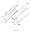
- the present inventors first conceived a method of press-forming two plates using a press die, forming folded plates 80 and 90 as shown in Fig. 20 , and further welding the folded plates 80 and 90 to form a sub-muffler outer cylinder having a polygonal cross-sectional shape. More particularly, a side part 80a of the plate 80 and a side part 90a of the plate 90 are welded and a side part 80c and a side part 90c are further welded.
- This method requires, however, a plurality of dedicated press dies depending on the cross-sectional shape of the sub-muffler outer cylinder, which increases the equipment cost.
- the present invention has been made in view of the aforementioned circumstances and aims to provide a manufacturing method and a manufacturing device of a sub-muffler outer cylinder capable of manufacturing a cylindrical-shaped body having a polygonal cross-sectional shape even with low-cost equipment.
- a manufacturing method of a sub-muffler outer cylinder according to the present invention includes pushing one push roll toward two receive rolls and then bending a plate-shape workpiece to form the sub-muffler outer cylinder made of a cylindrical-shaped body, in which an amount of a distance from the lowermost part of the push roll when the height of the lowermost part of the push roll is equal to the height of the uppermost part of the receive roll to the lowermost part of the push roll when the push roll is lowered (hereinafter, a push-in amount) in a part of the workpiece corresponding to a corner part of the cylindrical-shaped body is made larger than a push-in amount in a part of the workpiece corresponding to a side part of the cylindrical-shaped body to form the cylindrical-shaped body having a polygonal cross-sectional shape.
- the push roll and the two receive rolls may each have a truncated cone side surface. According to such a configuration, it is possible to form a tapered cylindrical-shaped body having a polygonal cross-sectional shape.
- the push roll and the two receive rolls may each have a column side surface. According to such a configuration, it is possible to form a straight cylindrical-shaped body having a polygonal cross-sectional shape without having a taper angle.
- a manufacturing device e.g., roll bending device of a sub-muffler outer cylinder according to the present invention includes one push roll, two receive rolls, a drive part (e.g., actuator, hydraulic cylinder) that pushes the push roll, and a controller (e.g., hydraulic controller) that controls the drive part, the manufacturing device pushing the push roll toward the receive rolls and then bending a workpiece to form the sub-muffler outer cylinder made of a cylindrical-shaped body, in which the controller controls a push-in amount in a part of the workpiece corresponding to a corner part of the cylindrical-shaped body to be larger than a push-in amount in a part of the workpiece corresponding to a side part of the cylindrical-shaped body.
- a drive part e.g., actuator, hydraulic cylinder
- a controller e.g., hydraulic controller
- the present invention it is possible to provide a manufacturing method and a manufacturing device of a sub-muffler outer cylinder capable of forming a cylindrical-shaped body having a polygonal cross-sectional shape even with low-cost equipment.
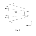
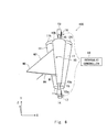
- Figs. 1 to 8 are schematic views showing processes of the manufacturing method according to the first embodiment.
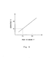
- Fig. 9 is a curvature with respect to a push-in amount by a roll.
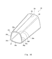
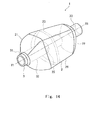
- Fig. 10 is a perspective view of a cylindrical-shaped body.
- Fig. 11 is an expansion view of the cylindrical-shaped body.
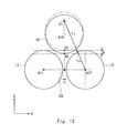
- Figs. 12 and 13 are schematic views for describing a relation among a dimension of a formed product, a radius of a roll, and the push-in amount by the roll.
- Fig. 14 is a perspective view of a sub-muffler.
- Fig. 1 to 8 are schematic views showing processes of the manufacturing method according to the first embodiment.
- Fig. 9 is a curvature with respect to a push-in amount by a roll.
- Fig. 10 is a perspective view of a cylindrical-shaped body.
- Fig. 11 is an expansion view of the cylindrical-shaped body.
- Figs. 12 and 13 are schematic views for describing a relation among
- FIG. 15 is a schematic view showing the sub-muffler arranged at the underside of a vehicle.
- a roll bending device 100 (may be referred to as a manufacturing device of a sub-muffler outer cylinder) includes a push roll 10, receive rolls 11 and 12, bearing housings 13 and 14, and hydraulic cylinders 16 and 17 (may be referred to as drive parts).
- the push roll 10 is a truncated cone that is supported by the bearing housings 13 and 14 via an axial member 15 and can be rotated around an axis A10.
- the rotation direction of the push roll 10 is represented by ⁇ - ⁇ .
- One end part 10b of the push roll 10 has a diameter larger than that of the other end part 10a.
- the push roll 10 has a tapered shape so as to be squeezed from one end part 10b toward the other end part 10a.
- the side surface of the push roll 10 (may be referred to as a truncated cone side surface) is inclined to the axis at a predetermined taper angle.
- the push roll 10 can be moved along the ⁇ -z direction by the hydraulic cylinders 16 and 17 via the bearing housings 13 and 14 and the axial member 15.
- the push roll 10 can be lowered, for example, toward the receive rolls 11 and 12.
- the receive rolls 11 and 12 are truncated cones that are supported by a supporting base (not shown) via an axial member (not shown) and can be respectively rotated around axes A11 and A12.
- the rotation directions of the receive rolls 11 and 12 are respectively represented by ⁇ - ⁇ and ⁇ - ⁇ .
- One end part 11b of the receive roll 11 has a diameter larger than that of the other end part 11a and one end part 12b of the receive roll 12 has a diameter larger than that of the other end part 12a.
- the receive roll 11 has a tapered shape so as to be squeezed from one end part 11b toward the other end part 11a.
- the receive roll 12 has a tapered shape so as to be squeezed from one end part 12b toward the other end part 12a.
- the side surfaces of the receive rolls 11 and 12 (may be referred to as truncated cone side surfaces) are inclined to the respective axes at a predetermined taper angle, which is similar to the side surface of the push roll 10.
- the receive rolls 11 and 12 are aligned with each other with a predetermined interval therebetween.
- the receive rolls 11 and 12 are fixed so that the axes of the receive rolls 11 and 12 are located in predetermined positions.
- the edge of the other end part 11a is shown to extend beyond the edge of one end part 11b on the ZX plane in Figs. 3 , 5 , and 8 , the edge of the other end part 11a and the edge of one end part 11b may accord with each other on the ZX plane.
- the edge of the other end part 12a extends beyond the edge of one end part 12b on the ZX plane, the edge of the other end part 12a and the edge of one end part 12b may accord with each other.
- the bearing housing 13 is arranged on one end part 10b of the push roll 10 and the bearing housing 14 is arranged on the other end part 10a of the push roll 10. Further, the bearing housings 13 and 14 are respectively supported by the hydraulic cylinders 16 and 17 so that the bearing housings 13 and 14 can be vertically moved.
- the hydraulic cylinders 16 and 17 are arranged below the bearing housings 13 and 14, respectively.
- the hydraulic cylinders 16 and 17 adjust a push-in amount by the push roll 10 via the bearing housings 13 and 14, respectively.
- the push-in amount means a distance from the lowermost part of the push roll 10 when the height of the lowermost part of the push roll 10 is equal to the height of the uppermost part of the receive roll 11 to the lowermost part of the push roll 10 when the push roll 10 is lowered (hereinafter, the push-in amount may be referred to as a push-in distance).
- the hydraulic cylinders 16 and 17 are able to change the push-in amount by the push roll 10 during a bending process so that the push-in distance of the push roll 10 changes according to the position of the workpiece.
- the hydraulic cylinders 16 and 17 may adjust the push-in amount by the push roll 10 by using, for example, a hydraulic controller 18 (may be referred to as a controller) that controls the amount of oil that flows through the hydraulic cylinders
- the workpiece W0 is a trapezoidal plate made of a material which can be roll-bended.
- the materials which can be roll-bended include, for example, a metallic material such as stainless steel.
- the workpiece W0 includes an upper base part W1 corresponding to the upper base of the trapezoid, a lower base part W2 corresponding to the lower base of the trapezoid, and leg parts W3 ( Fig. 3 ) and W4 corresponding to the legs of the trapezoid.
- the lower base part W2 of the trapezoid corresponds to the side longer than that of the upper base part W1.
- roll bending is performed so that the lower base part W2 passes through the side of one end part 10b while allowing the upper base part W1 of the workpiece W0 to pass through the side of the other end part 10a.
- the push roll 10 pushes the workpiece W0 at a predetermined push-in amount P1 while the workpiece W0 passes between the push roll 10 and the receive rolls 11 and 12.
- a side part 20a (see Figs. 10 and 11 ) having a curvature R1 is thus formed.
- the push roll 10 pushes the workpiece W0 at a push-in amount P2 which is larger than the push-in amount P1 while allowing the trapezoidal plate shape workpiece W0 to pass between the push roll 10 and the receive rolls 11 and 12 (corner part forming process S2).
- a corner part 20f (see Figs. 10 and 11 ) having a curvature R2 is thus formed.
- a curvature R of the bent formed product produced by the roll bending device may be, for example, proportional to a push-in amount L by the push roll.
- the corner part 20f is formed by being pressed at a push-in amount larger than that when the side part 20a is formed.
- the curvature R2 of the corner part 20f is larger than the curvature R1 of the side part 20a.
- the curvature R2 is preferably large since the large curvature makes the corner part 20f sharper.
- the side part forming process S1 and the corner part forming process S2 are alternated until the time that the leg part W3 and the leg part W4 face each other or come in contact with each other.
- the workpiece W0 is formed into a tapered cylindrical-shaped body 20 having a polygonal cross-sectional shape.
- the term "polygonal shape" in this specification not only means a completely polygonal shape but also means, for example, a substantially polygonal shape in which some or all of the corner parts are somewhat rounded or cut off or side parts have a predetermined curvature. As shown in Figs.
- the cylindrical-shaped body 20 includes side parts 20b, 20c, 20d, and 20e and corner parts 20g, 20h, and 20i.
- the side parts 20a, 20b, 20c, 20d, and 20e correspond to the sides of the polygon in the cross section of the cylindrical-shaped body 20
- the corner parts 20f, 20g, 20h, and 20i correspond to the corner parts of the polygon in the cross section of the cylindrical-shaped body 20.
- End parts 23 and 24 correspond to the leg parts W3 and W4, respectively.
- the curvature and the length of the side parts 20a, 20b, 20c, 20d, and 20e and the corner parts 20f, 20g, 20h, and 20i may be different from each other, and the curvature may be changed by changing the push-in amount.
- the upper base part W1 corresponds to one end part 21 of the cylindrical-shaped body 20 and the lower base part W2 corresponds to the other end part 22 of the cylindrical-shaped body 20.
- the cylindrical-shaped body 20 has a tapered shape so as to be squeezed to one end part 21 from the other end part 22.
- the radius corresponding to the curvature R of the cylindrical-shaped body 20 as a formed product is represented as rf
- the radius of the receive roll 12 is represented as r12
- the distance between the receive roll 11 and the receive roll 12 is represented as c.
- the position of the lowermost part of the push roll 10 when the height of the lowermost part of the push roll 10 is equal to the height of the uppermost part of the receive roll 11 is represented by an origin O1.
- a push-in amount b to a lowermost part 02 of the push roll 10 when the push roll 10 is lowered corresponds to the distance from the origin O1 to the lowermost part 02 of the push roll 10 when the push roll 10 is lowered.
- a right-angled triangle C1C3A12 is formed.
- the radius rf of the formed product can be approximated by Expression 2.
- the radius rf of the formed product is influenced by the radius r12 of the receive roll 12, the push-in amount b, and the distance c.
- the radius rf of the formed product is also influenced by the radius of the receive roll 11.
- the receive rolls 11 and 12 may be respectively moved in the ⁇ -x direction (see Fig. 3 ) and the y-x direction, for example, to change the distance c.
- end part 23 of the cylindrical-shaped body 20 and the end part 24 of the cylindrical-shaped body 20 may be welded together (welding process S3).
- welding process S3 By welding together the end part 23 and the end part 24, it is possible to form the cylindrical-shaped body which has no seam in the circumferential direction.
- the plate-shape workpiece W0 can be formed into cylindrical bodies having various cross-sectional shapes.
- the cylindrical-shaped body having a polygonal cross-sectional shape can be formed. Further, in the manufacturing method according to the first embodiment, a roll bending device having a general configuration that includes a push roll and receive rolls is used, and the necessary equipment cost is low. Further, it is possible to change the push-in amount according to the position of the workpiece by the hydraulic cylinder or the hydraulic controller, for example. According to this configuration, it is possible to manufacture cylindrical-shaped bodies having various polygonal cross-sectional shapes with a low equipment cost using a device having a general configuration without using equipment such as a plurality of press dies to form various cross-sectional shapes.
- a sub-muffler by performing processing such as a diameter reducing process to reduce the end part of the cylindrical-shaped body obtained by the manufacturing method according to the first embodiment or arranging a duct which is a flow path of exhaust gas in the cylindrical-shaped body obtained by the manufacturing method according to the first embodiment, it is possible to obtain, for example, a sub-muffler.
- a sub-muffler is a sub-muffler 1 shown in Fig. 14 .
- the sub-muffler 1 includes a cylindrical body 2 having a substantially trapezoidal cross-sectional shape, a separator 4, and a duct 3.
- the sub-muffler 1 is a separator-type sub-muffler including the separator 4.
- the cylindrical body 2 is obtained by processing the cylindrical-shaped body 20.
- the cylindrical body 2 includes a central part 29, an end part 21 extending in one side of the cylindrical body 2 from the central part 29, and an end part 22 extending in the other side thereof from the central part 29.
- the central part 29 has a substantially trapezoidal cross-sectional shape, and the cross-sectional profile has a decreasing diameter from the end part 21 to the end part 22.
- the central part 29 has a predetermined curvature about the axis of the cylindrical body 2, and has a high rigidity.
- the end part 21 and the end part 22 are obtained by performing processing such as pressing processing or spinning processing on the end part 21 (see Fig. 10 ) and the end part 22 (see Fig. 10 ) of the cylindrical-shaped body 20.
- the sub-muffler 1 is provided, for example, in the lower part of a floor surface 60 of the vehicle and is used.
- the floor surface 60 includes a concave part 61 recessed toward the vehicle interior and the cross-sectional shape of the concave part 61 is a trapezoidal shape.
- the cross-sectional shape of the cylindrical body 2 is a trapezoidal shape and the shape of the sub-muffler 1 corresponds to the shape of the concave part 61. Accordingly, the sub-muffler 1 is provided in the concave part 61 to fit inside the concave part 61, whereby it is possible to secure a large capacity.
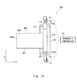
- FIGs. 16-19 are schematic views showing processes of the manufacturing method according to the second embodiment.
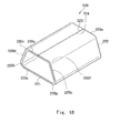
- Fig. 18 is a perspective view of a cylindrical-shaped body.
- Fig. 19 is a perspective view of a sub-muffler.
- the bearing housings 13 and 14 and the hydraulic cylinders 16 and 17 are not shown for the sake of clarity of the drawing.
- the manufacturing device used in the manufacturing method according to the second embodiment includes the same configurations as those of the roll bending device 100 except for the configurations of the push roll and the receive rolls. Elements of this embodiment which are the same as those of the first embodiment are denoted by the same reference symbols as those of the first embodiment and the descriptions thereof will be omitted.
- a roll bending device 200 includes a push roll 210 and receive rolls 211 and 212.
- the push roll 210 is a columnar body that is supported by the bearing housings 13 and 14 via the axial member 15 and can be rotated around the axis.
- the side surface of the push roll 210 (may be referred to as a column side surface) is substantially parallel to the axis. That is, the push roll 210 has a straight shape, not a tapered shape, and has a taper angle of about 0°.
- the push roll 210 is vertically moved by the hydraulic cylinders 16 and 17 via the bearing housings 13 and 14 and the axial member 15. The push roll 210 can be lowered, for example, toward the receive rolls 211 and 212.
- the receive rolls 211 and 212 are columnar bodies that are supported by a supporting base (not shown) via an axial member (not shown) and can be rotated around an axis.
- the side surfaces of the receive rolls 211 and 212 (may be referred to as column side surfaces) are parallel to the axis, which is similar to the side surface of the push roll 210.
- the receive rolls 211 and 212 do not have a tapered shape and the taper angle is substantially 0°.
- the receive rolls 211 and 212 are aligned with each other with a predetermined interval therebetween.
- the receive rolls 211 and 212 are fixed so that the axes of the receive rolls 211 and 212 are located in predetermined positions.
- the hydraulic cylinders 16 and 17 adjust the push-in amount by the push roll 210 via the bearing housings 13 and 14, respectively.
- the hydraulic cylinders 16 and 17 can change the push-in amount by the push roll 10 during the forming process so that the push-in distance of the push roll 210 changes depending on the position of the workpiece.
- roll bending is performed by pushing the push roll 210 toward the receive rolls 211 and 212 while allowing a trapezoidal plate shape workpiece W20 to pass between the push roll 210 and the receive rolls 211 and 212 (side part forming process S21).
- the workpiece W20 is a rectangular plate made of a material which can be roll-bended.
- the workpiece W20 includes short-side parts W23 and W24 corresponding to the short sides of the rectangle and long-side parts W21 and W22 corresponding to the long sides of the rectangle.
- the push roll 210 pushes the workpiece W20 at a predetermined push-in amount P1.
- a side part 220a (see Fig. 18 ) having a curvature R1 is thus formed.
- the push roll 210 pushes the workpiece W20 at a push-in amount P2 which is larger than the push-in amount P1 while allowing the workpiece W20 to pass between the push roll 210 and the receive rolls 211 and 212 (corner part forming process S22).
- a corner part 220f (see Fig. 18 ) having a curvature R2 is thus formed.
- the curvature R of the bent formed product produced by the roll bending device may be proportional to the push-in amount L by the push roll.
- the corner part 220f due to the drop of the push roll 210, the corner part 220f is formed by being pressed at a push-in amount larger than that when the side part 220a is formed. Therefore, the corner part 220f has a curvature larger than the curvature R1 of the side part 220a.
- the curvature R2 is preferably large since the large curvature R2 makes the corner part 220f sharper.
- the side part forming process S21 and the corner part forming process S22 are alternated until the time that the short-side parts W23 and W24 face each other or come in contact with each other.
- side parts 220b, 220c, 220d, and 220e and corner parts 220g, 220h, and 220i are formed in the workpiece W20.
- the workpiece W0 is formed into a straight cylindrical-shaped body 220 having a polygonal cross-sectional shape without having a taper angle.
- the side surface of the cylindrical-shaped body 220 is parallel to the axis.
- the side parts 220a, 220b, 220c, 220d, and 220e correspond to the sides of the polygon in the cross section of the cylindrical-shaped body 220
- the corner parts 220f, 220g, 220h, and 220i correspond to the corner parts of the polygon in the cross section of the cylindrical-shaped body 220.
- the curvature and the length of the side parts 220a, 220b, 220c, 220d, and 220e and the corner parts 220f, 220g, 220h, and 220i may be different from each other.
- the push-in amount P1 in the side part forming process S21 may be 0 (zero).
- the curvature R of the side parts 220a, 220b, 220c, 220d, and 220e becomes 0 and the shape of the side parts 220a, 220b, 220c, 220d, and 220e becomes flat.
- the cylindrical body having a polygonal cross-sectional shape can be formed.
- the push-in amount can be changed depending on the position of the workpiece using a roll bending device having a general configuration that includes a push roll and receive rolls. Accordingly, it is possible to manufacture cylindrical-shaped bodies having polygonal cross-sectional shapes by only using a device having a general configuration without using equipment such as a plurality of press dies to form various cross-sectional shapes.
- a sub-muffler by performing processing such as a diameter reducing process to reduce the end part of the cylindrical-shaped body 220 obtained by the manufacturing method according to the second embodiment or arranging a duct which is a flow path of exhaust gas in the cylindrical-shaped body 220 obtained by the manufacturing method according to the second embodiment, it is possible to obtain, for example, a sub-muffler.
- a sub-muffler is a sub-muffler 201 shown in Fig. 19 .
- the sub-muffler 201 includes a cylindrical body 202 (may be referred to as a sub-muffler outer cylinder) having a substantially trapezoidal cross-sectional shape and a duct 203.
- the cylindrical body 202 is obtained by processing the cylindrical-shaped body 220.
- the cylindrical body 202 includes a central part 229, an end part 221 extending in one side of the cylindrical body 202 from the central part 229, and an end part 222 extending in the other side thereof from the central part 229.
- the central part 229 has a substantially trapezoidal cross-sectional shape and the cross-sectional shape is substantially constant from the side of the end part 221 to the end part 222.
- the central part 229 has a predetermined curvature about the axis of the cylindrical body 202 and has a high rigidity.
- the end part 221 and the end part 222 are obtained by performing processing such as pressing processing or spinning processing on one end part 221 and the other end part 222 (see Fig. 18 ) of the cylindrical-shaped body 220.
- the sub-muffler 201 can be provided, similar to the sub-muffler 1, in the concave part 61 to fit inside the concave part 61 of the floor surface 60 of the vehicle (see Fig. 15 ). Therefore, it can be ensured that the sub-muffler 201 has a large capacity, which is similar to the sub-muffler 1.
- the present invention is not limited to the above first and second embodiments and may be changed as appropriate without departing from the spirit of the present invention.
- the two receive rolls 11 and 12 may instead be pushed toward the push roll 10.
- the order of the side part forming process S1 or S21 and the corner part forming process S2 or S22 or the number of times that these processes are repeated can be changed as appropriate.
- the roll bending device used in the manufacturing method according to the first and second embodiments may further include a roll opposed to the push roll 10 on the side of the two receive rolls 11 and 12.
- the roll bending device according to the first embodiment uses the hydraulic cylinders 16 and 17 to push the push roll
- an actuator or it may be referred to as a drive part
- Such an actuator may include, for example, a hydraulic motor.
- a fan plate shape workpiece may be used instead.
- the workpiece is passed between the push roll and the receive rolls once in the manufacturing method according to the first and second embodiments, the workpiece may be passed between them a plurality of times.
- cylindrical-shaped bodies having various taper angles can be manufactured. It is thus possible to change the taper angle of the cylindrical-shaped body obtained by forming the workpiece.
- a resistance may be given to a part near the upper base part W1 or a part near the lower base part W2 of the workpiece W0 by a roller or a weight to slide the workpiece and the push roll or the receive roll to change the speed at which the workpiece W0 passes in one end part 10b or the other end part 10a having a diameter smaller than that of one end part lOb. It is therefore possible to change the taper angle of the cylindrical-shaped body obtained by forming the workpiece.
- a manufacturing method of a sub-muffler outer cylinder (20, 220) comprising pushing one push roll (10, 210) toward two receive rolls (11, 12, 211, 212) and then bending a plate-shape workpiece (W0, W20) to form the sub-muffler outer cylinder (20, 220) made of a cylindrical-shaped body.
- a push-in amount in a part (20f ⁇ 20g, 220f ⁇ 220g) of the workpiece corresponding to a corner part of the cylindrical-shaped body is made larger than a push-in amount in a part (20a ⁇ 20e, 220a ⁇ 220e) of the workpiece corresponding to a side part of the cylindrical-shaped body to form the cylindrical-shaped body (20, 220) having a polygonal cross-sectional shape.
Landscapes
- Engineering & Computer Science (AREA)
- Mechanical Engineering (AREA)
- Chemical & Material Sciences (AREA)
- Combustion & Propulsion (AREA)
- General Engineering & Computer Science (AREA)
- Bending Of Plates, Rods, And Pipes (AREA)
Abstract
Description
- The present invention relates to a manufacturing method and a manufacturing device of a sub-muffler outer cylinder, and more particularly, to a manufacturing method and a manufacturing device of a sub-muffler outer cylinder to form a cylindrical-shaped body having a polygonal cross-sectional shape.
- A tapered cylindrical-shaped body may be manufactured by bending a trapezoidal plate shape workpiece or a fan plate shape workpiece. In a process of bending the workpiece, a roll bending method is used, for example.
- For example, Japanese Unexamined Patent Application Publication No.
2012-236207 - Incidentally, there has been demanded, for example, for a sub-muffler outer cylinder having a polygonal cross-sectional shape such as a trapezoidal shape. The present inventors first conceived a method of press-forming two plates using a press die, forming folded
plates Fig. 20 , and further welding the foldedplates side part 80a of theplate 80 and aside part 90a of theplate 90 are welded and aside part 80c and aside part 90c are further welded. This method requires, however, a plurality of dedicated press dies depending on the cross-sectional shape of the sub-muffler outer cylinder, which increases the equipment cost. - The present invention has been made in view of the aforementioned circumstances and aims to provide a manufacturing method and a manufacturing device of a sub-muffler outer cylinder capable of manufacturing a cylindrical-shaped body having a polygonal cross-sectional shape even with low-cost equipment.
- A manufacturing method of a sub-muffler outer cylinder according to the present invention includes pushing one push roll toward two receive rolls and then bending a plate-shape workpiece to form the sub-muffler outer cylinder made of a cylindrical-shaped body, in which an amount of a distance from the lowermost part of the push roll when the height of the lowermost part of the push roll is equal to the height of the uppermost part of the receive roll to the lowermost part of the push roll when the push roll is lowered (hereinafter, a push-in amount) in a part of the workpiece corresponding to a corner part of the cylindrical-shaped body is made larger than a push-in amount in a part of the workpiece corresponding to a side part of the cylindrical-shaped body to form the cylindrical-shaped body having a polygonal cross-sectional shape.
- According to such a configuration, it is possible to manufacture a sub-muffler outer cylinder having a polygonal cross-sectional shape even with low-cost equipment.
- Further, the push roll and the two receive rolls may each have a truncated cone side surface. According to such a configuration, it is possible to form a tapered cylindrical-shaped body having a polygonal cross-sectional shape.
- Further, the push roll and the two receive rolls may each have a column side surface. According to such a configuration, it is possible to form a straight cylindrical-shaped body having a polygonal cross-sectional shape without having a taper angle.
- On the other hand, a manufacturing device (e.g., roll bending device) of a sub-muffler outer cylinder according to the present invention includes one push roll, two receive rolls, a drive part (e.g., actuator, hydraulic cylinder) that pushes the push roll, and a controller (e.g., hydraulic controller) that controls the drive part, the manufacturing device pushing the push roll toward the receive rolls and then bending a workpiece to form the sub-muffler outer cylinder made of a cylindrical-shaped body, in which the controller controls a push-in amount in a part of the workpiece corresponding to a corner part of the cylindrical-shaped body to be larger than a push-in amount in a part of the workpiece corresponding to a side part of the cylindrical-shaped body.
- According to such a configuration, it is possible to manufacture a sub-muffler outer cylinder having a polygonal cross-sectional shape with low-cost equipment.
- According to the present invention, it is possible to provide a manufacturing method and a manufacturing device of a sub-muffler outer cylinder capable of forming a cylindrical-shaped body having a polygonal cross-sectional shape even with low-cost equipment.
- The above and other objects, features and advantages of the present invention will become more fully understood from the detailed description given hereinbelow and the accompanying drawings which are given by way of illustration only, and thus are not to be considered as limiting the present invention.
-
-
Figs. 1 to 8 are schematic views showing processes of a manufacturing method according to a first embodiment; -
Fig. 9 is a curvature with respect to a push-in amount by a roll; -
Fig. 10 is a perspective view of a cylindrical-shaped body; -
Fig. 11 is an expansion view of the cylindrical-shaped body; -
Figs. 12 and13 are schematic views for describing a relation among a dimension of a formed product, a radius of a roll, and the push-in amount by the roll; -
Fig. 14 is a perspective view of a sub-muffler; -
Fig. 15 is a schematic view showing the sub-muffler arranged at the underside of a vehicle; -
Figs. 16 and17 are schematic views showing processes of a manufacturing method according to a second embodiment; -
Fig. 18 is a perspective view of a cylindrical-shaped body; -
Fig. 19 is a perspective view of a sub-muffler; and -
Fig. 20 is a perspective view of two plates formed using a press die. - With reference to
Figs. 1 to 15 , a manufacturing method according to a first embodiment will be described.Figs. 1 to 8 are schematic views showing processes of the manufacturing method according to the first embodiment.Fig. 9 is a curvature with respect to a push-in amount by a roll.Fig. 10 is a perspective view of a cylindrical-shaped body.Fig. 11 is an expansion view of the cylindrical-shaped body.Figs. 12 and13 are schematic views for describing a relation among a dimension of a formed product, a radius of a roll, and the push-in amount by the roll.Fig. 14 is a perspective view of a sub-muffler.Fig. 15 is a schematic view showing the sub-muffler arranged at the underside of a vehicle. InFigs. 2-5 ,7 , and8 , for the sake of clarity of the drawings, bearinghousings 13 and 14 (described later) andhydraulic cylinders 16 and 17 (described later) are not shown. - First, a manufacturing device used in the manufacturing method according to the first embodiment will be described. As shown in
Figs. 1-3 , a roll bending device 100 (may be referred to as a manufacturing device of a sub-muffler outer cylinder) includes apush roll 10, receiverolls housings hydraulic cylinders 16 and 17 (may be referred to as drive parts). - The
push roll 10 is a truncated cone that is supported by the bearinghousings axial member 15 and can be rotated around an axis A10. The rotation direction of thepush roll 10 is represented by α-θ. Oneend part 10b of thepush roll 10 has a diameter larger than that of theother end part 10a. Thepush roll 10 has a tapered shape so as to be squeezed from oneend part 10b toward theother end part 10a. The side surface of the push roll 10 (may be referred to as a truncated cone side surface) is inclined to the axis at a predetermined taper angle. Thepush roll 10 can be moved along the α-z direction by thehydraulic cylinders housings axial member 15. Thepush roll 10 can be lowered, for example, toward thereceive rolls - The receive
rolls receive rolls end part 11b of the receiveroll 11 has a diameter larger than that of theother end part 11a and oneend part 12b of the receiveroll 12 has a diameter larger than that of theother end part 12a. The receiveroll 11 has a tapered shape so as to be squeezed from oneend part 11b toward theother end part 11a. In a similar way, the receiveroll 12 has a tapered shape so as to be squeezed from oneend part 12b toward theother end part 12a. The side surfaces of thereceive rolls 11 and 12 (may be referred to as truncated cone side surfaces) are inclined to the respective axes at a predetermined taper angle, which is similar to the side surface of thepush roll 10. The receiverolls rolls receive rolls other end part 11a is shown to extend beyond the edge of oneend part 11b on the ZX plane inFigs. 3 ,5 , and8 , the edge of theother end part 11a and the edge of oneend part 11b may accord with each other on the ZX plane. Similarly, while the edge of theother end part 12a extends beyond the edge of oneend part 12b on the ZX plane, the edge of theother end part 12a and the edge of oneend part 12b may accord with each other. - The bearing
housing 13 is arranged on oneend part 10b of thepush roll 10 and the bearinghousing 14 is arranged on theother end part 10a of thepush roll 10. Further, the bearinghousings hydraulic cylinders housings - The
hydraulic cylinders housings hydraulic cylinders push roll 10 via the bearinghousings push roll 10 when the height of the lowermost part of thepush roll 10 is equal to the height of the uppermost part of the receiveroll 11 to the lowermost part of thepush roll 10 when thepush roll 10 is lowered (hereinafter, the push-in amount may be referred to as a push-in distance). Thehydraulic cylinders push roll 10 during a bending process so that the push-in distance of the push roll 10 changes according to the position of the workpiece. Thehydraulic cylinders push roll 10 by using, for example, a hydraulic controller 18 (may be referred to as a controller) that controls the amount of oil that flows through thehydraulic cylinders - Next, the manufacturing method according to the first embodiment will be described. As shown in
Figs. 1 ,4 , and5 , thepush roll 10 is pushed toward the receive rolls 11 and 12 while allowing a trapezoidal plate shape workpiece W0 to pass between thepush roll 10 and the receive rolls 11 and 12 to perform roll bending (side part forming process S1). The workpiece W0 is a trapezoidal plate made of a material which can be roll-bended. The materials which can be roll-bended include, for example, a metallic material such as stainless steel. The workpiece W0 includes an upper base part W1 corresponding to the upper base of the trapezoid, a lower base part W2 corresponding to the lower base of the trapezoid, and leg parts W3 (Fig. 3 ) and W4 corresponding to the legs of the trapezoid. The lower base part W2 of the trapezoid corresponds to the side longer than that of the upper base part W1. - Typically, roll bending is performed so that the lower base part W2 passes through the side of one
end part 10b while allowing the upper base part W1 of the workpiece W0 to pass through the side of theother end part 10a. Thepush roll 10 pushes the workpiece W0 at a predetermined push-in amount P1 while the workpiece W0 passes between thepush roll 10 and the receive rolls 11 and 12. Aside part 20a (seeFigs. 10 and11 ) having a curvature R1 is thus formed. - Subsequently, as shown in
Figs. 6 to 8 , thepush roll 10 pushes the workpiece W0 at a push-in amount P2 which is larger than the push-in amount P1 while allowing the trapezoidal plate shape workpiece W0 to pass between thepush roll 10 and the receive rolls 11 and 12 (corner part forming process S2). Acorner part 20f (seeFigs. 10 and11 ) having a curvature R2 is thus formed. As shown inFig. 9 , a curvature R of the bent formed product produced by the roll bending device may be, for example, proportional to a push-in amount L by the push roll. In such a case, due to the drop of thepush roll 10, thecorner part 20f is formed by being pressed at a push-in amount larger than that when theside part 20a is formed. Thus the curvature R2 of thecorner part 20f is larger than the curvature R1 of theside part 20a. The curvature R2 is preferably large since the large curvature makes thecorner part 20f sharper. - Next, the side part forming process S1 and the corner part forming process S2 are alternated until the time that the leg part W3 and the leg part W4 face each other or come in contact with each other. As shown in
Fig. 10 , the workpiece W0 is formed into a tapered cylindrical-shapedbody 20 having a polygonal cross-sectional shape. The term "polygonal shape" in this specification not only means a completely polygonal shape but also means, for example, a substantially polygonal shape in which some or all of the corner parts are somewhat rounded or cut off or side parts have a predetermined curvature. As shown inFigs. 10 and11 , the cylindrical-shapedbody 20 includesside parts corner parts side parts body 20, and thecorner parts body 20.End parts side parts corner parts end part 21 of the cylindrical-shapedbody 20 and the lower base part W2 corresponds to theother end part 22 of the cylindrical-shapedbody 20. The cylindrical-shapedbody 20 has a tapered shape so as to be squeezed to oneend part 21 from theother end part 22. - Now, a relation among the dimension of the formed product, the roll diameter, and the push-in amount will be described. As shown in
Fig. 12 , the radius corresponding to the curvature R of the cylindrical-shapedbody 20 as a formed product is represented as rf, the radius of the receiveroll 12 is represented as r12, and the distance between the receiveroll 11 and the receiveroll 12 is represented as c. As shown inFig. 13 , the position of the lowermost part of thepush roll 10 when the height of the lowermost part of thepush roll 10 is equal to the height of the uppermost part of the receiveroll 11 is represented by an origin O1. A push-in amount b to alowermost part 02 of thepush roll 10 when thepush roll 10 is lowered corresponds to the distance from the origin O1 to thelowermost part 02 of thepush roll 10 when thepush roll 10 is lowered. As shown inFig. 12 , by connecting a center C1 of the circle for the radius rf, a midpoint C3 of the axis A11 and the axis A12, and the axis A11, a right-angled triangle C1C3A12 is formed. By using the Pythagorean theorem for the right-angled triangle - C1C3A11, the radius rf of the dimension of the formed product, the radius r12 of the roll, and the push-in amount b are expressed by the following
Expression 1.
- Solving
Expression 1 for rf obtainsExpression 2.
- The radius rf of the formed product can be approximated by
Expression 2. According toExpression 2, the radius rf of the formed product is influenced by the radius r12 of the receiveroll 12, the push-in amount b, and the distance c. In a similar way, the radius rf of the formed product is also influenced by the radius of the receiveroll 11. Accordingly, in order to adjust the radius rf of the formed product, the receive rolls 11 and 12 may be respectively moved in the β-x direction (seeFig. 3 ) and the y-x direction, for example, to change the distance c. By taking into consideration the plate thickness and the material properties of the workpiece W0, and the influence of the friction among the workpiece W0, thepush roll 10, and the receive rolls 11 and 12, it is possible to calculate the radius rf of the cylindrical-shapedbody 20 more accurately. - Next, the
end part 23 of the cylindrical-shapedbody 20 and theend part 24 of the cylindrical-shapedbody 20 may be welded together (welding process S3). By welding together theend part 23 and theend part 24, it is possible to form the cylindrical-shaped body which has no seam in the circumferential direction. - By changing the push-in amount in each of the side part forming process S1 and the corner part forming process S2 and the number of times that these processes are repeated, the plate-shape workpiece W0 can be formed into cylindrical bodies having various cross-sectional shapes.
- From the above description, according to the manufacturing method of the first embodiment, the cylindrical-shaped body having a polygonal cross-sectional shape can be formed. Further, in the manufacturing method according to the first embodiment, a roll bending device having a general configuration that includes a push roll and receive rolls is used, and the necessary equipment cost is low. Further, it is possible to change the push-in amount according to the position of the workpiece by the hydraulic cylinder or the hydraulic controller, for example. According to this configuration, it is possible to manufacture cylindrical-shaped bodies having various polygonal cross-sectional shapes with a low equipment cost using a device having a general configuration without using equipment such as a plurality of press dies to form various cross-sectional shapes.
- Incidentally, by performing processing such as a diameter reducing process to reduce the end part of the cylindrical-shaped body obtained by the manufacturing method according to the first embodiment or arranging a duct which is a flow path of exhaust gas in the cylindrical-shaped body obtained by the manufacturing method according to the first embodiment, it is possible to obtain, for example, a sub-muffler. One example of such a sub-muffler is a sub-muffler 1 shown in
Fig. 14 . Thesub-muffler 1 includes acylindrical body 2 having a substantially trapezoidal cross-sectional shape, aseparator 4, and aduct 3. Thesub-muffler 1 is a separator-type sub-muffler including theseparator 4. Thecylindrical body 2 is obtained by processing the cylindrical-shapedbody 20. Thecylindrical body 2 includes acentral part 29, anend part 21 extending in one side of thecylindrical body 2 from thecentral part 29, and anend part 22 extending in the other side thereof from thecentral part 29. Thecentral part 29 has a substantially trapezoidal cross-sectional shape, and the cross-sectional profile has a decreasing diameter from theend part 21 to theend part 22. Thecentral part 29 has a predetermined curvature about the axis of thecylindrical body 2, and has a high rigidity. Theend part 21 and theend part 22 are obtained by performing processing such as pressing processing or spinning processing on the end part 21 (seeFig. 10 ) and the end part 22 (seeFig. 10 ) of the cylindrical-shapedbody 20. - As shown in
Fig. 15 , thesub-muffler 1 is provided, for example, in the lower part of afloor surface 60 of the vehicle and is used. Thefloor surface 60 includes aconcave part 61 recessed toward the vehicle interior and the cross-sectional shape of theconcave part 61 is a trapezoidal shape. The cross-sectional shape of thecylindrical body 2 is a trapezoidal shape and the shape of thesub-muffler 1 corresponds to the shape of theconcave part 61. Accordingly, thesub-muffler 1 is provided in theconcave part 61 to fit inside theconcave part 61, whereby it is possible to secure a large capacity. - With reference to
Figs. 16-19 , a manufacturing method according to a second embodiment will be described.Figs. 16 and17 are schematic views showing processes of the manufacturing method according to the second embodiment.Fig. 18 is a perspective view of a cylindrical-shaped body.Fig. 19 is a perspective view of a sub-muffler. InFig. 17 , the bearinghousings hydraulic cylinders - First, a manufacturing device used in the manufacturing method according to the second embodiment will be described. The manufacturing device used in the manufacturing method according to the second embodiment includes the same configurations as those of the
roll bending device 100 except for the configurations of the push roll and the receive rolls. Elements of this embodiment which are the same as those of the first embodiment are denoted by the same reference symbols as those of the first embodiment and the descriptions thereof will be omitted. - As shown in
Figs. 16 and17 , aroll bending device 200 includes apush roll 210 and receiverolls - The
push roll 210 is a columnar body that is supported by the bearinghousings axial member 15 and can be rotated around the axis. The side surface of the push roll 210 (may be referred to as a column side surface) is substantially parallel to the axis. That is, thepush roll 210 has a straight shape, not a tapered shape, and has a taper angle of about 0°. Thepush roll 210 is vertically moved by thehydraulic cylinders housings axial member 15. Thepush roll 210 can be lowered, for example, toward the receiverolls - The receive rolls 211 and 212 are columnar bodies that are supported by a supporting base (not shown) via an axial member (not shown) and can be rotated around an axis. The side surfaces of the receive
rolls 211 and 212 (may be referred to as column side surfaces) are parallel to the axis, which is similar to the side surface of thepush roll 210. In summary, the receiverolls rolls - The
hydraulic cylinders push roll 210 via the bearinghousings hydraulic cylinders push roll 10 during the forming process so that the push-in distance of thepush roll 210 changes depending on the position of the workpiece. - Next, the manufacturing method according to the second embodiment will be described. First, similar to the manufacturing method according to the first embodiment, roll bending is performed by pushing the
push roll 210 toward the receiverolls push roll 210 and the receiverolls 211 and 212 (side part forming process S21). The workpiece W20 is a rectangular plate made of a material which can be roll-bended. The workpiece W20 includes short-side parts W23 and W24 corresponding to the short sides of the rectangle and long-side parts W21 and W22 corresponding to the long sides of the rectangle. When the workpiece W20 passes between thepush roll 210 and the receiverolls push roll 210 pushes the workpiece W20 at a predetermined push-in amount P1. Aside part 220a (seeFig. 18 ) having a curvature R1 is thus formed. - Next, the
push roll 210 pushes the workpiece W20 at a push-in amount P2 which is larger than the push-in amount P1 while allowing the workpiece W20 to pass between thepush roll 210 and the receiverolls 211 and 212 (corner part forming process S22). Acorner part 220f (seeFig. 18 ) having a curvature R2 is thus formed. As shown inFig. 9 , for example, the curvature R of the bent formed product produced by the roll bending device may be proportional to the push-in amount L by the push roll. In such a case, due to the drop of thepush roll 210, thecorner part 220f is formed by being pressed at a push-in amount larger than that when theside part 220a is formed. Therefore, thecorner part 220f has a curvature larger than the curvature R1 of theside part 220a. The curvature R2 is preferably large since the large curvature R2 makes thecorner part 220f sharper. - Next, the side part forming process S21 and the corner part forming process S22 are alternated until the time that the short-side parts W23 and W24 face each other or come in contact with each other. As shown in
Fig. 18 ,side parts corner parts Fig. 18 , the workpiece W0 is formed into a straight cylindrical-shapedbody 220 having a polygonal cross-sectional shape without having a taper angle. The side surface of the cylindrical-shapedbody 220 is parallel to the axis. Theside parts body 220, and thecorner parts body 220. The curvature and the length of theside parts corner parts - Further, while the side part forming process S21 and the corner part forming process S22 are alternated in the manufacturing method according to the second embodiment, the push-in amount P1 in the side part forming process S21 may be 0 (zero). When the push-in amount P1 in the side part forming process S21 is 0 (zero), the curvature R of the
side parts side parts - As seen from the above description, according to the manufacturing method of the second embodiment, the cylindrical body having a polygonal cross-sectional shape can be formed. Further, in the manufacturing method according to the second embodiment, the push-in amount can be changed depending on the position of the workpiece using a roll bending device having a general configuration that includes a push roll and receive rolls. Accordingly, it is possible to manufacture cylindrical-shaped bodies having polygonal cross-sectional shapes by only using a device having a general configuration without using equipment such as a plurality of press dies to form various cross-sectional shapes.
- Incidentally, by performing processing such as a diameter reducing process to reduce the end part of the cylindrical-shaped
body 220 obtained by the manufacturing method according to the second embodiment or arranging a duct which is a flow path of exhaust gas in the cylindrical-shapedbody 220 obtained by the manufacturing method according to the second embodiment, it is possible to obtain, for example, a sub-muffler. One example of such a sub-muffler is a sub-muffler 201 shown inFig. 19 . The sub-muffler 201 includes a cylindrical body 202 (may be referred to as a sub-muffler outer cylinder) having a substantially trapezoidal cross-sectional shape and aduct 203. Thecylindrical body 202 is obtained by processing the cylindrical-shapedbody 220. Thecylindrical body 202 includes acentral part 229, anend part 221 extending in one side of thecylindrical body 202 from thecentral part 229, and anend part 222 extending in the other side thereof from thecentral part 229. Thecentral part 229 has a substantially trapezoidal cross-sectional shape and the cross-sectional shape is substantially constant from the side of theend part 221 to theend part 222. Thecentral part 229 has a predetermined curvature about the axis of thecylindrical body 202 and has a high rigidity. Theend part 221 and theend part 222 are obtained by performing processing such as pressing processing or spinning processing on oneend part 221 and the other end part 222 (seeFig. 18 ) of the cylindrical-shapedbody 220. The sub-muffler 201 can be provided, similar to thesub-muffler 1, in theconcave part 61 to fit inside theconcave part 61 of thefloor surface 60 of the vehicle (seeFig. 15 ). Therefore, it can be ensured that the sub-muffler 201 has a large capacity, which is similar to thesub-muffler 1. - Note that the present invention is not limited to the above first and second embodiments and may be changed as appropriate without departing from the spirit of the present invention. For example, while the
push roll 10 is pushed toward the two receiverolls rolls push roll 10. Further, the order of the side part forming process S1 or S21 and the corner part forming process S2 or S22 or the number of times that these processes are repeated can be changed as appropriate. Further, the roll bending device used in the manufacturing method according to the first and second embodiments may further include a roll opposed to thepush roll 10 on the side of the two receiverolls hydraulic cylinders - Further, in the manufacturing method according to the first embodiment, by changing the combination of the push-in amount by the push roll 10 (see
Fig. 1 ) in oneend part 10b and the push-in amount in theother end part 10a, cylindrical-shaped bodies having various taper angles can be manufactured. It is thus possible to change the taper angle of the cylindrical-shaped body obtained by forming the workpiece. - Further, while the taper angle of the formed product is determined by the taper angle of the
push roll 10 or the receive rolls 11 and 12 in the manufacturing method according to the first embodiment, a resistance may be given to a part near the upper base part W1 or a part near the lower base part W2 of the workpiece W0 by a roller or a weight to slide the workpiece and the push roll or the receive roll to change the speed at which the workpiece W0 passes in oneend part 10b or theother end part 10a having a diameter smaller than that of one end part lOb. It is therefore possible to change the taper angle of the cylindrical-shaped body obtained by forming the workpiece. - From the invention thus described, it will be obvious that the embodiments of the invention may be varied in many ways. Such variations are not to be regarded as a departure from the spirit and scope of the invention, and all such modifications as would be obvious to one skilled in the art are intended for inclusion within the scope of the following claims.
- Provided is a manufacturing method of a sub-muffler outer cylinder (20, 220), the manufacturing method comprising pushing one push roll (10, 210) toward two receive rolls (11, 12, 211, 212) and then bending a plate-shape workpiece (W0, W20) to form the sub-muffler outer cylinder (20, 220) made of a cylindrical-shaped body. A push-in amount in a part (
20f∼
Claims (4)
- A manufacturing method of a sub-muffler outer cylinder, the manufacturing method comprising pushing one push roll toward two receive rolls and then bending a plate-shape workpiece to form the sub-muffler outer cylinder made of a cylindrical-shaped body,
wherein a push-in amount in a part of the workpiece corresponding to a corner part of the cylindrical-shaped body is made larger than a push-in amount in a part of the workpiece corresponding to a side part of the cylindrical-shaped body to form the cylindrical-shaped body having a polygonal cross-sectional shape. - The manufacturing method of the sub-muffler outer cylinder according to Claim 1, wherein the push roll and the two receive rolls each have a truncated cone side surface.
- The manufacturing method of the sub-muffler outer cylinder according to Claim 1, wherein the push roll and the two receive rolls each have a column side surface.
- A manufacturing device of a sub-muffler outer cylinder comprising one push roll, two receive rolls, a drive part that pushes the push roll, and a controller that controls the drive part, the manufacturing device pushing the push roll toward the receive rolls and then bending a workpiece to form the sub-muffler outer cylinder made of a cylindrical-shaped body,
wherein the controller controls a push-in amount in a part of the workpiece corresponding to a corner part of the cylindrical-shaped body to be larger than a push-in amount in a part of the workpiece corresponding to a side part of the cylindrical-shaped body.
Applications Claiming Priority (1)
| Application Number | Priority Date | Filing Date | Title |
|---|---|---|---|
| JP2014112297A JP6020515B2 (en) | 2014-05-30 | 2014-05-30 | Sub-muffler outer cylinder manufacturing method and manufacturing apparatus |
Publications (2)
| Publication Number | Publication Date |
|---|---|
| EP2949406A1 true EP2949406A1 (en) | 2015-12-02 |
| EP2949406B1 EP2949406B1 (en) | 2021-03-17 |
Family
ID=53539460
Family Applications (1)
| Application Number | Title | Priority Date | Filing Date |
|---|---|---|---|
| EP15169538.4A Not-in-force EP2949406B1 (en) | 2014-05-30 | 2015-05-28 | Manufacturing method and manufacturing device of sub-muffler outer cylinder |
Country Status (4)
| Country | Link |
|---|---|
| US (1) | US10016801B2 (en) |
| EP (1) | EP2949406B1 (en) |
| JP (1) | JP6020515B2 (en) |
| CN (1) | CN105268788B (en) |
Cited By (1)
| Publication number | Priority date | Publication date | Assignee | Title |
|---|---|---|---|---|
| CN112642900A (en) * | 2020-12-02 | 2021-04-13 | 太原科技大学 | Common-roller type rolling equipment for metal polar plates |
Families Citing this family (2)
| Publication number | Priority date | Publication date | Assignee | Title |
|---|---|---|---|---|
| JP6056781B2 (en) * | 2013-04-10 | 2017-01-11 | トヨタ自動車株式会社 | Muffler manufacturing method and muffler |
| KR101799440B1 (en) * | 2016-06-10 | 2017-11-20 | 한승철 | Bending device for manufacturing hopper of cylinder type |
Citations (5)
| Publication number | Priority date | Publication date | Assignee | Title |
|---|---|---|---|---|
| US2674294A (en) * | 1953-02-19 | 1954-04-06 | Broderna Ekbergs Platslagerifa | Plate bending machine |
| GB960708A (en) * | 1959-11-16 | 1964-06-17 | Albino Ferranti | Improvements in or relating to sheet bending and other rolls |
| JPH0796330A (en) * | 1993-09-30 | 1995-04-11 | Kuramoto Kogyo Kk | Taper bending device |
| JP2000033426A (en) * | 1998-07-17 | 2000-02-02 | Isel Co Ltd | Roll bending method and device |
| JP2012236207A (en) | 2011-05-11 | 2012-12-06 | Kurimoto Ltd | Bending roll device |
Family Cites Families (13)
| Publication number | Priority date | Publication date | Assignee | Title |
|---|---|---|---|---|
| US4030335A (en) * | 1975-03-13 | 1977-06-21 | Walter Allenspach | Multi-function metal-working machine |
| US4195509A (en) * | 1976-06-12 | 1980-04-01 | Hinrichs Gesellschaft Mit Beschrankter Haftung | Device for bending ring segment-shaped plate blanks into conically shaped parts |
| US4047411A (en) * | 1977-01-03 | 1977-09-13 | The Boeing Company | Numerically controlled pyramid roll forming machine |
| JPS5557324A (en) * | 1978-10-19 | 1980-04-28 | Osaka Kanagata Kogyo Kk | Bending roll machine |
| KR870001074B1 (en) * | 1980-09-19 | 1987-06-04 | Kenneth Michael Hume | Method for rolling to plate |
| JPS57127524A (en) * | 1981-01-31 | 1982-08-07 | Nippon Radiator Co Ltd | Bending press for metallic plate |
| JPS5916627A (en) * | 1982-07-19 | 1984-01-27 | Nippon Soken Inc | Method and apparatus for manufacturing conical pipe |
| ATE47676T1 (en) * | 1985-06-04 | 1989-11-15 | Haeusler Ag Chr | PROCESS FOR MANUFACTURING A CONUS SHELL USING A ROLLER SHEET METAL ROUNDING MACHINE AND MACHINE FOR CARRYING OUT THE PROCESS. |
| JPH0688077B2 (en) * | 1986-01-31 | 1994-11-09 | 株式会社日立製作所 | Iron plate bending method and device |
| JP3191268B2 (en) * | 1997-02-07 | 2001-07-23 | 株式会社栗本鐵工所 | Molding method of elliptical cylinder |
| DE102006050116B3 (en) * | 2006-10-25 | 2008-04-24 | Weil Engineering Gmbh | Round bending machine to shape workpiece from cutout has counter-element in form of bending table to carry cutout |
| CN101327497A (en) * | 2008-07-28 | 2008-12-24 | 区沃钜 | Novel automatic wheel base adjusting curved surface roller press |
| CN203044592U (en) * | 2012-12-20 | 2013-07-10 | 中铁二十一局集团第三工程有限公司 | Automatic plate bending roll convenient to use |
-
2014
- 2014-05-30 JP JP2014112297A patent/JP6020515B2/en not_active Expired - Fee Related
-
2015
- 2015-05-27 CN CN201510278122.1A patent/CN105268788B/en not_active Expired - Fee Related
- 2015-05-28 US US14/723,750 patent/US10016801B2/en active Active
- 2015-05-28 EP EP15169538.4A patent/EP2949406B1/en not_active Not-in-force
Patent Citations (5)
| Publication number | Priority date | Publication date | Assignee | Title |
|---|---|---|---|---|
| US2674294A (en) * | 1953-02-19 | 1954-04-06 | Broderna Ekbergs Platslagerifa | Plate bending machine |
| GB960708A (en) * | 1959-11-16 | 1964-06-17 | Albino Ferranti | Improvements in or relating to sheet bending and other rolls |
| JPH0796330A (en) * | 1993-09-30 | 1995-04-11 | Kuramoto Kogyo Kk | Taper bending device |
| JP2000033426A (en) * | 1998-07-17 | 2000-02-02 | Isel Co Ltd | Roll bending method and device |
| JP2012236207A (en) | 2011-05-11 | 2012-12-06 | Kurimoto Ltd | Bending roll device |
Cited By (1)
| Publication number | Priority date | Publication date | Assignee | Title |
|---|---|---|---|---|
| CN112642900A (en) * | 2020-12-02 | 2021-04-13 | 太原科技大学 | Common-roller type rolling equipment for metal polar plates |
Also Published As
| Publication number | Publication date |
|---|---|
| US20150343509A1 (en) | 2015-12-03 |
| CN105268788A (en) | 2016-01-27 |
| JP6020515B2 (en) | 2016-11-02 |
| EP2949406B1 (en) | 2021-03-17 |
| US10016801B2 (en) | 2018-07-10 |
| CN105268788B (en) | 2018-03-27 |
| JP2015223629A (en) | 2015-12-14 |
Similar Documents
| Publication | Publication Date | Title |
|---|---|---|
| EP2949406A1 (en) | Manufacturing method and manufacturing device of sub-muffler outer cylinder | |
| US10449995B2 (en) | Hollow rack bar and method of manufacturing the hollow rack bar | |
| EP2823909A1 (en) | Roller bearing cage and manufacturing method therefor as well as roller bearing manufacturing method | |
| EP2942120A1 (en) | Roll-bending process apparatus and roll-bending process method | |
| KR101747017B1 (en) | Method of producing shaped steel changing in cross-sectional shape in longitudinal direction and roll forming apparatus for same | |
| EP2857117B1 (en) | Method of forming structure having closed cross section, and device for forming structure having closed cross section | |
| US8646303B2 (en) | Process for producing a profile from a flat metal strip | |
| EP2662162A1 (en) | Roller hemming device | |
| US9669444B2 (en) | Method of manufacturing curvilineal closed structure parts without flange and apparatus for the same | |
| US11453042B2 (en) | Forging roll device | |
| JP6479556B2 (en) | Rolling device, bending method | |
| US9470124B2 (en) | Sub-muffler and manufacturing method of sub-muffler | |
| US20240100583A1 (en) | Burring processing method, burring processing mold, burring processing device, and burring processed product | |
| WO2014192043A1 (en) | Method for press-molding steel pipe and method for producing steel pipe | |
| EP3345690A1 (en) | Hole-widening machining method, molding tool, molding and machining method | |
| US20180021836A1 (en) | Method of manufacturing tooth-shaped component, and tooth-shaped component | |
| EP3248708B1 (en) | Method of manufacturing a toothed part | |
| TWI574752B (en) | A method of manufacturing a steel sheet having a cross-sectional shape in the direction of the long side and a roll forming apparatus | |
| US20160114366A1 (en) | Apparatus and method for the continuous and progressive shaping of metal strips to give a profile with longitudinally varying cross section | |
| US20180021832A1 (en) | Method of incremental cold forming an angled corner in a continuous sheet of advanced high strength metal | |
| WO2011125968A1 (en) | Method for manufacturing wheel rim for vehicle | |
| KR101630213B1 (en) | Apparatus for manufacturing shaft formed helical spline and method for manufacturing shaft formed helical spline | |
| JP2014101980A (en) | Temporary assembly of retainer for roller bearing, its process of manufacture and process of manufacture of roller bearing | |
| JP2015064100A (en) | Method for manufacturing waveform holder and waveform holder | |
| KR101576401B1 (en) | Method for manufacturing multi-stage gear, and multi-stage gear |
Legal Events
| Date | Code | Title | Description |
|---|---|---|---|
| 17P | Request for examination filed |
Effective date: 20150528 |
|
| AK | Designated contracting states |
Kind code of ref document: A1 Designated state(s): AL AT BE BG CH CY CZ DE DK EE ES FI FR GB GR HR HU IE IS IT LI LT LU LV MC MK MT NL NO PL PT RO RS SE SI SK SM TR |
|
| AX | Request for extension of the european patent |
Extension state: BA ME |
|
| PUAI | Public reference made under article 153(3) epc to a published international application that has entered the european phase |
Free format text: ORIGINAL CODE: 0009012 |
|
| STAA | Information on the status of an ep patent application or granted ep patent |
Free format text: STATUS: EXAMINATION IS IN PROGRESS |
|
| 17Q | First examination report despatched |
Effective date: 20170403 |
|
| GRAP | Despatch of communication of intention to grant a patent |
Free format text: ORIGINAL CODE: EPIDOSNIGR1 |
|
| STAA | Information on the status of an ep patent application or granted ep patent |
Free format text: STATUS: GRANT OF PATENT IS INTENDED |
|
| INTG | Intention to grant announced |
Effective date: 20201203 |
|
| GRAS | Grant fee paid |
Free format text: ORIGINAL CODE: EPIDOSNIGR3 |
|
| GRAA | (expected) grant |
Free format text: ORIGINAL CODE: 0009210 |
|
| STAA | Information on the status of an ep patent application or granted ep patent |
Free format text: STATUS: THE PATENT HAS BEEN GRANTED |
|
| AK | Designated contracting states |
Kind code of ref document: B1 Designated state(s): AL AT BE BG CH CY CZ DE DK EE ES FI FR GB GR HR HU IE IS IT LI LT LU LV MC MK MT NL NO PL PT RO RS SE SI SK SM TR |
|
| REG | Reference to a national code |
Ref country code: GB Ref legal event code: FG4D |
|
| RIN1 | Information on inventor provided before grant (corrected) |
Inventor name: YAMAMOTO, AKIYOSHI Inventor name: HOMMA, HIDEKI |
|
| REG | Reference to a national code |
Ref country code: CH Ref legal event code: EP |
|
| REG | Reference to a national code |
Ref country code: DE Ref legal event code: R096 Ref document number: 602015066889 Country of ref document: DE |
|
| REG | Reference to a national code |
Ref country code: IE Ref legal event code: FG4D |
|
| REG | Reference to a national code |
Ref country code: AT Ref legal event code: REF Ref document number: 1371764 Country of ref document: AT Kind code of ref document: T Effective date: 20210415 |
|
| REG | Reference to a national code |
Ref country code: LT Ref legal event code: MG9D |
|
| PG25 | Lapsed in a contracting state [announced via postgrant information from national office to epo] |
Ref country code: FI Free format text: LAPSE BECAUSE OF FAILURE TO SUBMIT A TRANSLATION OF THE DESCRIPTION OR TO PAY THE FEE WITHIN THE PRESCRIBED TIME-LIMIT Effective date: 20210317 Ref country code: HR Free format text: LAPSE BECAUSE OF FAILURE TO SUBMIT A TRANSLATION OF THE DESCRIPTION OR TO PAY THE FEE WITHIN THE PRESCRIBED TIME-LIMIT Effective date: 20210317 Ref country code: GR Free format text: LAPSE BECAUSE OF FAILURE TO SUBMIT A TRANSLATION OF THE DESCRIPTION OR TO PAY THE FEE WITHIN THE PRESCRIBED TIME-LIMIT Effective date: 20210618 Ref country code: BG Free format text: LAPSE BECAUSE OF FAILURE TO SUBMIT A TRANSLATION OF THE DESCRIPTION OR TO PAY THE FEE WITHIN THE PRESCRIBED TIME-LIMIT Effective date: 20210617 Ref country code: NO Free format text: LAPSE BECAUSE OF FAILURE TO SUBMIT A TRANSLATION OF THE DESCRIPTION OR TO PAY THE FEE WITHIN THE PRESCRIBED TIME-LIMIT Effective date: 20210617 |
|
| REG | Reference to a national code |
Ref country code: AT Ref legal event code: MK05 Ref document number: 1371764 Country of ref document: AT Kind code of ref document: T Effective date: 20210317 |
|
| REG | Reference to a national code |
Ref country code: NL Ref legal event code: MP Effective date: 20210317 |
|
| PG25 | Lapsed in a contracting state [announced via postgrant information from national office to epo] |
Ref country code: LV Free format text: LAPSE BECAUSE OF FAILURE TO SUBMIT A TRANSLATION OF THE DESCRIPTION OR TO PAY THE FEE WITHIN THE PRESCRIBED TIME-LIMIT Effective date: 20210317 Ref country code: RS Free format text: LAPSE BECAUSE OF FAILURE TO SUBMIT A TRANSLATION OF THE DESCRIPTION OR TO PAY THE FEE WITHIN THE PRESCRIBED TIME-LIMIT Effective date: 20210317 Ref country code: SE Free format text: LAPSE BECAUSE OF FAILURE TO SUBMIT A TRANSLATION OF THE DESCRIPTION OR TO PAY THE FEE WITHIN THE PRESCRIBED TIME-LIMIT Effective date: 20210317 |
|
| PG25 | Lapsed in a contracting state [announced via postgrant information from national office to epo] |
Ref country code: NL Free format text: LAPSE BECAUSE OF FAILURE TO SUBMIT A TRANSLATION OF THE DESCRIPTION OR TO PAY THE FEE WITHIN THE PRESCRIBED TIME-LIMIT Effective date: 20210317 |
|
| PG25 | Lapsed in a contracting state [announced via postgrant information from national office to epo] |
Ref country code: SM Free format text: LAPSE BECAUSE OF FAILURE TO SUBMIT A TRANSLATION OF THE DESCRIPTION OR TO PAY THE FEE WITHIN THE PRESCRIBED TIME-LIMIT Effective date: 20210317 Ref country code: LT Free format text: LAPSE BECAUSE OF FAILURE TO SUBMIT A TRANSLATION OF THE DESCRIPTION OR TO PAY THE FEE WITHIN THE PRESCRIBED TIME-LIMIT Effective date: 20210317 Ref country code: EE Free format text: LAPSE BECAUSE OF FAILURE TO SUBMIT A TRANSLATION OF THE DESCRIPTION OR TO PAY THE FEE WITHIN THE PRESCRIBED TIME-LIMIT Effective date: 20210317 Ref country code: CZ Free format text: LAPSE BECAUSE OF FAILURE TO SUBMIT A TRANSLATION OF THE DESCRIPTION OR TO PAY THE FEE WITHIN THE PRESCRIBED TIME-LIMIT Effective date: 20210317 Ref country code: AT Free format text: LAPSE BECAUSE OF FAILURE TO SUBMIT A TRANSLATION OF THE DESCRIPTION OR TO PAY THE FEE WITHIN THE PRESCRIBED TIME-LIMIT Effective date: 20210317 |
|
| PG25 | Lapsed in a contracting state [announced via postgrant information from national office to epo] |
Ref country code: SK Free format text: LAPSE BECAUSE OF FAILURE TO SUBMIT A TRANSLATION OF THE DESCRIPTION OR TO PAY THE FEE WITHIN THE PRESCRIBED TIME-LIMIT Effective date: 20210317 Ref country code: RO Free format text: LAPSE BECAUSE OF FAILURE TO SUBMIT A TRANSLATION OF THE DESCRIPTION OR TO PAY THE FEE WITHIN THE PRESCRIBED TIME-LIMIT Effective date: 20210317 Ref country code: ES Free format text: LAPSE BECAUSE OF FAILURE TO SUBMIT A TRANSLATION OF THE DESCRIPTION OR TO PAY THE FEE WITHIN THE PRESCRIBED TIME-LIMIT Effective date: 20210317 Ref country code: PL Free format text: LAPSE BECAUSE OF FAILURE TO SUBMIT A TRANSLATION OF THE DESCRIPTION OR TO PAY THE FEE WITHIN THE PRESCRIBED TIME-LIMIT Effective date: 20210317 Ref country code: PT Free format text: LAPSE BECAUSE OF FAILURE TO SUBMIT A TRANSLATION OF THE DESCRIPTION OR TO PAY THE FEE WITHIN THE PRESCRIBED TIME-LIMIT Effective date: 20210719 Ref country code: IS Free format text: LAPSE BECAUSE OF FAILURE TO SUBMIT A TRANSLATION OF THE DESCRIPTION OR TO PAY THE FEE WITHIN THE PRESCRIBED TIME-LIMIT Effective date: 20210717 |
|
| REG | Reference to a national code |
Ref country code: DE Ref legal event code: R097 Ref document number: 602015066889 Country of ref document: DE |
|
| REG | Reference to a national code |
Ref country code: CH Ref legal event code: PL |
|
| PLBE | No opposition filed within time limit |
Free format text: ORIGINAL CODE: 0009261 |
|
| STAA | Information on the status of an ep patent application or granted ep patent |
Free format text: STATUS: NO OPPOSITION FILED WITHIN TIME LIMIT |
|
| PG25 | Lapsed in a contracting state [announced via postgrant information from national office to epo] |
Ref country code: LI Free format text: LAPSE BECAUSE OF NON-PAYMENT OF DUE FEES Effective date: 20210531 Ref country code: LU Free format text: LAPSE BECAUSE OF NON-PAYMENT OF DUE FEES Effective date: 20210528 Ref country code: MC Free format text: LAPSE BECAUSE OF FAILURE TO SUBMIT A TRANSLATION OF THE DESCRIPTION OR TO PAY THE FEE WITHIN THE PRESCRIBED TIME-LIMIT Effective date: 20210317 Ref country code: CH Free format text: LAPSE BECAUSE OF NON-PAYMENT OF DUE FEES Effective date: 20210531 Ref country code: AL Free format text: LAPSE BECAUSE OF FAILURE TO SUBMIT A TRANSLATION OF THE DESCRIPTION OR TO PAY THE FEE WITHIN THE PRESCRIBED TIME-LIMIT Effective date: 20210317 Ref country code: DK Free format text: LAPSE BECAUSE OF FAILURE TO SUBMIT A TRANSLATION OF THE DESCRIPTION OR TO PAY THE FEE WITHIN THE PRESCRIBED TIME-LIMIT Effective date: 20210317 |
|
| REG | Reference to a national code |
Ref country code: BE Ref legal event code: MM Effective date: 20210531 |
|
| 26N | No opposition filed |
Effective date: 20211220 |
|
| GBPC | Gb: european patent ceased through non-payment of renewal fee |
Effective date: 20210617 |
|
| PG25 | Lapsed in a contracting state [announced via postgrant information from national office to epo] |
Ref country code: SI Free format text: LAPSE BECAUSE OF FAILURE TO SUBMIT A TRANSLATION OF THE DESCRIPTION OR TO PAY THE FEE WITHIN THE PRESCRIBED TIME-LIMIT Effective date: 20210317 |
|
| PG25 | Lapsed in a contracting state [announced via postgrant information from national office to epo] |
Ref country code: IT Free format text: LAPSE BECAUSE OF FAILURE TO SUBMIT A TRANSLATION OF THE DESCRIPTION OR TO PAY THE FEE WITHIN THE PRESCRIBED TIME-LIMIT Effective date: 20210317 Ref country code: IE Free format text: LAPSE BECAUSE OF NON-PAYMENT OF DUE FEES Effective date: 20210528 Ref country code: GB Free format text: LAPSE BECAUSE OF NON-PAYMENT OF DUE FEES Effective date: 20210617 |
|
| PG25 | Lapsed in a contracting state [announced via postgrant information from national office to epo] |
Ref country code: IS Free format text: LAPSE BECAUSE OF FAILURE TO SUBMIT A TRANSLATION OF THE DESCRIPTION OR TO PAY THE FEE WITHIN THE PRESCRIBED TIME-LIMIT Effective date: 20210717 |
|
| PG25 | Lapsed in a contracting state [announced via postgrant information from national office to epo] |
Ref country code: BE Free format text: LAPSE BECAUSE OF NON-PAYMENT OF DUE FEES Effective date: 20210531 |
|
| PGFP | Annual fee paid to national office [announced via postgrant information from national office to epo] |
Ref country code: FR Payment date: 20220408 Year of fee payment: 8 Ref country code: DE Payment date: 20220406 Year of fee payment: 8 |
|
| PG25 | Lapsed in a contracting state [announced via postgrant information from national office to epo] |
Ref country code: HU Free format text: LAPSE BECAUSE OF FAILURE TO SUBMIT A TRANSLATION OF THE DESCRIPTION OR TO PAY THE FEE WITHIN THE PRESCRIBED TIME-LIMIT; INVALID AB INITIO Effective date: 20150528 |
|
| P01 | Opt-out of the competence of the unified patent court (upc) registered |
Effective date: 20230427 |
|
| PG25 | Lapsed in a contracting state [announced via postgrant information from national office to epo] |
Ref country code: CY Free format text: LAPSE BECAUSE OF FAILURE TO SUBMIT A TRANSLATION OF THE DESCRIPTION OR TO PAY THE FEE WITHIN THE PRESCRIBED TIME-LIMIT Effective date: 20210317 |
|
| REG | Reference to a national code |
Ref country code: DE Ref legal event code: R119 Ref document number: 602015066889 Country of ref document: DE |
|
| PG25 | Lapsed in a contracting state [announced via postgrant information from national office to epo] |
Ref country code: MK Free format text: LAPSE BECAUSE OF FAILURE TO SUBMIT A TRANSLATION OF THE DESCRIPTION OR TO PAY THE FEE WITHIN THE PRESCRIBED TIME-LIMIT Effective date: 20210317 Ref country code: DE Free format text: LAPSE BECAUSE OF NON-PAYMENT OF DUE FEES Effective date: 20231201 |
|
| PG25 | Lapsed in a contracting state [announced via postgrant information from national office to epo] |
Ref country code: FR Free format text: LAPSE BECAUSE OF NON-PAYMENT OF DUE FEES Effective date: 20230531 |
|
| PG25 | Lapsed in a contracting state [announced via postgrant information from national office to epo] |
Ref country code: MT Free format text: LAPSE BECAUSE OF FAILURE TO SUBMIT A TRANSLATION OF THE DESCRIPTION OR TO PAY THE FEE WITHIN THE PRESCRIBED TIME-LIMIT Effective date: 20210317 |
|
| PG25 | Lapsed in a contracting state [announced via postgrant information from national office to epo] |
Ref country code: TR Free format text: LAPSE BECAUSE OF FAILURE TO SUBMIT A TRANSLATION OF THE DESCRIPTION OR TO PAY THE FEE WITHIN THE PRESCRIBED TIME-LIMIT Effective date: 20210317 |