EP2949400A2 - Extension pole mechanism for paint roller - Google Patents
Extension pole mechanism for paint roller Download PDFInfo
- Publication number
- EP2949400A2 EP2949400A2 EP15166144.4A EP15166144A EP2949400A2 EP 2949400 A2 EP2949400 A2 EP 2949400A2 EP 15166144 A EP15166144 A EP 15166144A EP 2949400 A2 EP2949400 A2 EP 2949400A2
- Authority
- EP
- European Patent Office
- Prior art keywords
- housing
- contact
- respect
- pole
- biasing
- Prior art date
- Legal status (The legal status is an assumption and is not a legal conclusion. Google has not performed a legal analysis and makes no representation as to the accuracy of the status listed.)
- Granted
Links
Images












Classifications
-
- B—PERFORMING OPERATIONS; TRANSPORTING
- B25—HAND TOOLS; PORTABLE POWER-DRIVEN TOOLS; MANIPULATORS
- B25G—HANDLES FOR HAND IMPLEMENTS
- B25G1/00—Handle constructions
- B25G1/04—Handle constructions telescopic; extensible; sectional
-
- B—PERFORMING OPERATIONS; TRANSPORTING
- B05—SPRAYING OR ATOMISING IN GENERAL; APPLYING FLUENT MATERIALS TO SURFACES, IN GENERAL
- B05B—SPRAYING APPARATUS; ATOMISING APPARATUS; NOZZLES
- B05B15/00—Details of spraying plant or spraying apparatus not otherwise provided for; Accessories
- B05B15/60—Arrangements for mounting, supporting or holding spraying apparatus
- B05B15/62—Arrangements for supporting spraying apparatus, e.g. suction cups
- B05B15/628—Arrangements for supporting spraying apparatus, e.g. suction cups of variable length
-
- B—PERFORMING OPERATIONS; TRANSPORTING
- B05—SPRAYING OR ATOMISING IN GENERAL; APPLYING FLUENT MATERIALS TO SURFACES, IN GENERAL
- B05C—APPARATUS FOR APPLYING FLUENT MATERIALS TO SURFACES, IN GENERAL
- B05C17/00—Hand tools or apparatus using hand held tools, for applying liquids or other fluent materials to, for spreading applied liquids or other fluent materials on, or for partially removing applied liquids or other fluent materials from, surfaces
- B05C17/02—Rollers ; Hand tools comprising coating rollers or coating endless belts
- B05C17/0205—Rollers ; Hand tools comprising coating rollers or coating endless belts characterised by the handle, e.g. handle shape or material
-
- B—PERFORMING OPERATIONS; TRANSPORTING
- B05—SPRAYING OR ATOMISING IN GENERAL; APPLYING FLUENT MATERIALS TO SURFACES, IN GENERAL
- B05C—APPARATUS FOR APPLYING FLUENT MATERIALS TO SURFACES, IN GENERAL
- B05C17/00—Hand tools or apparatus using hand held tools, for applying liquids or other fluent materials to, for spreading applied liquids or other fluent materials on, or for partially removing applied liquids or other fluent materials from, surfaces
- B05C17/02—Rollers ; Hand tools comprising coating rollers or coating endless belts
- B05C17/0217—Rollers ; Hand tools comprising coating rollers or coating endless belts comprising a frame supporting the coating roller at both ends or being intented to be hold at both ends by the user
-
- F—MECHANICAL ENGINEERING; LIGHTING; HEATING; WEAPONS; BLASTING
- F16—ENGINEERING ELEMENTS AND UNITS; GENERAL MEASURES FOR PRODUCING AND MAINTAINING EFFECTIVE FUNCTIONING OF MACHINES OR INSTALLATIONS; THERMAL INSULATION IN GENERAL
- F16B—DEVICES FOR FASTENING OR SECURING CONSTRUCTIONAL ELEMENTS OR MACHINE PARTS TOGETHER, e.g. NAILS, BOLTS, CIRCLIPS, CLAMPS, CLIPS OR WEDGES; JOINTS OR JOINTING
- F16B7/00—Connections of rods or tubes, e.g. of non-circular section, mutually, including resilient connections
- F16B7/10—Telescoping systems
- F16B7/14—Telescoping systems locking in intermediate non-discrete positions
Definitions
- This invention is in the field of methods and apparatuses for extending and contracting the length of poles used with paint related accessories and more specifically to methods and apparatuses for an extendable pole mechanism that is easily adjusted between a use condition and an adjustment condition with one hand.
- adjustable length poles that are designed to connect to and disconnect from paint accessories.
- a painter for example, requires the pole holding a paint roller to be at a relatively shorter length when painting a surface at waist height but to be at a relatively longer length when painting a surface far above his/her head.
- Known adjustable length poles have disadvantages.
- adjustable length poles are difficult and time consuming to use. Some, for example, require two hands to adjust. Another disadvantage is that they easily come "loose” from their setting, causing the poles to change their length when such change is not desirable. Yet another disadvantage is that many adjustable length poles are only adjustable in discrete length increments. Still another disadvantage is that known adjustable length poles quickly wear out, increasing costs.
- an extendable pole mechanism may be used with a first associated pole that is longitudinally movable with respect to a second associated pole to adjust the overall length of both poles.
- the extendable pole mechanism may comprise: a housing that receives the first and second associated poles; a first contact device that: (1) is supported to the housing; (2) is moveable with respect to the housing; and, (3) comprises first and second arms that receive the first associated pole; a second contact device that: (1) is supported to the housing; (2) is moveable with respect to the housing; and, (3) comprises first and second arms that receive the first associated pole; a first lever that is: (1) is supported to the housing; and, (2) is moveable with respect to the housing; a second lever that is: (1) is supported to the housing; and, (2) is moveable with respect to the housing; and, a trigger that is: (1) is supported to the housing; and, (2) is moveable with respect to the housing.
- the extendable pole mechanism may be adjustable by moving the trigger with respect to the housing to cause the first and second levers to move with respect to the housing to cause the first and second contact devices to move with respect to the housing between: (1) a use condition where the first associated pole is held by contact with the first and second contact devices in a longitudinally fixed position with respect to the second associated pole; and, (2) an adjustment condition where: (a) the first associated pole is not held by contact with the first and second contact devices in a longitudinally fixed position with respect to the second associated pole; and, (b) the first associated pole is longitudinally moveable with respect to the second associated pole.
- a first biasing device may exert a first biasing force that biases the first contact device toward contact with the first associated pole.
- a second biasing device may exert a second biasing force that biases the second contact device toward contact with the first associated pole.
- an extendable pole mechanism may be used with a first associated pole that is longitudinally movable with respect to a second associated pole to adjust the overall length of both poles.
- the extendable pole mechanism may comprise: a housing that receives the first and second associated poles; a first contact device that: (1) is supported to the housing; and, (2) is moveable with respect to the housing; a second contact device that: (1) is supported to the housing; and, (2) is moveable with respect to the housing; a first lever that is: (1) is supported to the housing; and, (2) is moveable with respect to the housing; a second lever that is: (1) is supported to the housing; and, (2) is moveable with respect to the housing; and, a trigger that is: (1) is supported to the housing; and, (2) is moveable with respect to the housing.
- the extendable pole mechanism may be adjustable by moving the trigger with respect to the housing to cause the first and second levers to move with respect to the housing to cause the first and second contact devices to move with respect to the housing between: (1) a use condition where the first associated pole is held by contact with the first and second contact devices in a longitudinally fixed position with respect to the second associated pole; and, (2) an adjustment condition where: (a) the first associated pole is not held by contact with the first and second contact devices in a longitudinally fixed position with respect to the second associated pole; and, (b) the first associated pole is longitudinally moveable with respect to the second associated pole.
- a method may comprise the steps of: (A) providing an extendable pole mechanism for use with a first pole that is longitudinally movable with respect to a second pole, the extendable pole mechanism comprising: (1) a housing that receives the first and second poles; (2) a first contact device that: (a) is supported to the housing; and, (b) is moveable with respect to the housing; (3) a second contact device that: (a) is supported to the housing; and, (b) is moveable with respect to the housing; (4) a first lever that is: (a) is supported to the housing; and, (b) is moveable with respect to the housing; (5) a second lever that is: (a) is supported to the housing; and, (b) is moveable with respect to the housing; and, (6) a trigger that is: (a) is supported to the housing; and, (b) is moveable with respect to the housing; and, (B) adjusting the extendable pole mechanism by moving the trigger with respect to the housing to cause the first
- FIGURES 1 and 17 show a pair of poles 10, 12 that can be used with the extendable pole mechanism 50 of this invention. While the extendable pole mechanism 50 is ideally suited for use with paint accessories and the like, such as the paint roller 20 shown in FIGURE 17 , it is not limited to that application.
- Pole 10 may have an outside diameter that is received within an inside diameter of pole 12. As a result, pole 10 is slideable within pole 12 (and with respect to pole 12) in first direction 14 and second direction 16. When pole 10 is slid in direction 14, the overall length of both poles is decreased.
- Pole 10 When pole 10 is slid in direction 16, the overall length of both poles is increased. Thus, a user can adjust the overall length of the poles by sliding pole 10 with respect to pole 12.
- Pole 10 may have a connection site 18 to which a paint accessory, such as paint roller 20, can be attached.
- Pole 12 and/or the housing may serve as a handle for the user.
- pole 10 is made of aluminum and pole 12 is made of fiberglass to provide good performance.
- the extendable pole mechanism 50 may be adjusted between a use condition, where pole 10 is held in a longitudinally fixed position with respect to pole 12, and an adjustment condition, where pole 10 can be slide longitudinally with respect to pole 12 so that the overall length can be changed.
- the extendable pole mechanism 50 may include a housing 52, a trigger 54, a cam lever 56, a cam holder 58, a push member 60, and a biasing device 62, which may be a spring, as shown.
- the housing 52 may have first and second portions 64, 66 that receive portions of poles 12 and 14, as shown, and may be attached to each other using connectors 68 received in openings 70. While six threaded connectors are used in the embodiment shown, the number and type can be any chosen with the sound judgment of a person of skill in the art.
- the first housing portion 64 may include shaft receiving grooves 72, an external protection ring 74, internal lateral extensions 76 and an internal longitudinal extension 78.
- a groove 80 may be formed between some of the lateral extensions 76, as shown.
- the external protection ring 74 shown only extends a small amount around the external surface of the portion 64.
- the second housing portion 66 may include shaft receiving grooves 82 and an external protection ring 84 that may extend all the way around the external surface of the portion 66, as shown.
- the second housing portion 66 may have internal lateral extensions 86 and pole contact surfaces 88. Extensions 90 may define grooves 92 between them, as shown. The purposes for these components will be discussed below.
- the trigger 54 may have a body 94 having a mid-section 96 and a pair or arms 98, 98 extending from the mid-section 96.
- the body 94 is C-shaped.
- a pair of hands 100, 100 may extend from distal ends of the arms 98, 98, as shown.
- the hands 100, 100 may extend inwardly and may have curved inner surfaces 104, as shown.
- a pair of shaft portions 102, 102 may extend from the distal ends of the arms 98, 98.
- the hands 100, 100 are attached to the shaft portions 102, 102 and extend inwardly therefrom.
- the trigger 54 may be formed of any material chosen with the sound judgment of a person of skill in the art. In one embodiment, the trigger 54 is made of plastic and in another it is made of a metal.
- the cam lever 56 may have a body 106 having a mid-section 108 and a pair of arms 110, 110 extending from the mid-section 108.
- the body 106 is C-shaped.
- First and second surfaces 112, 114 may extend longitudinally from the mid-section 108 as shown.
- the first surface 112 may extend above the second surface 114 and may be curved, as shown, to match the outside diameter of pole 10.
- Shoulder surfaces 116, 116 may be formed at proximal ends of the arms 110, 110 and the distal ends of the arms 110, 110 may curve inwardly, as shown.
- the cam lever 56 may be formed of any material chosen with the sound judgment of a person of skill in the art.
- the cam holder 58 may have a body 118 having a mid-section 120 and a pair or arms 122, 122 extending from the mid-section 120.
- the body 118 is C-shaped.
- a pair of surfaces 124, 124 may define with the mid-section 120 a groove 126 on the external surface of the mid-section 120, as shown.
- Hands 128, 128 may extend longitudinally from distal ends of the arms 122, 122, as shown.
- Contact surfaces 130, 130 may be defined on the hands 128, 128.
- the contact surfaces 130, 130 may be J-shaped, as shown.
- the cam holder 58 may be formed of any material chosen with the sound judgment of a person of skill in the art.
- the push member 60 may have first and second ends 132, 134, a top 136 and a bottom 138.
- a chamber 140 may be provided on the top 136, first end 132 and may receive the biasing device 62 shown in FIGURE 1 .
- the chamber 140 may be defined by a wall 142 at one end and may have a generally cylindrical shape, as shown.
- a slot 144 may be formed in a surface defining the bottom of the chamber 140 and may extend from the first end 132 toward the mid-section of the push member 60.
- Pole contact surfaces 146, 146 may extend from the bottom 138 and may be curved, as shown, to match the outside diameter of pole 10.
- Grooves 148, 148 may be formed on sides of the push member 60 and a groove 150 may be formed on the bottom 138 of the push member 60, as shown.
- the second end 134 may have an extension 152.
- the push member 60 may be formed of any material chosen with the sound judgment of a person of skill in the art.
- the poles 10, 12 may be received in the housing portions 64, 66 as shown in FIGURES 1 , 15 and 17 .
- the push member 60 may be positioned primarily within the housing portion 64, between lateral extensions 76, as shown in FIGURE 15 , and the slot 144 may receive the extension 78.
- the pole contact surfaces 146 may receive the outer surface of the pole 10, though pole 10 is hidden in FIGURES 15 and 16 .
- the shaft portions 102 of the trigger 54 may be received in the shaft receiving grooves 72 and 82 of the respective housing portions 64, 66.
- the hands 100 of the trigger 54 may be positioned within the grooves 148 formed on the push member 60, as seen in FIGURE 16 .
- the pole 10 may be received between the arms 98 of the trigger 54 and the mid-section 96 and arms 98 of the trigger 54 may be positioned outside the housing 52.
- the cam holder 58 may be positioned within the housing 52 with the mid-section 120, see FIGURES 9-10 , received in the groove 80, see FIGURE 3 , formed in the first housing portion 64. This is shown in FIGURE 15 .
- the pole 10 may be received between the arms 122 of the cam holder 58.
- the hands 128 of the cam holder 58 may be received in the grooves 92, 92, see FIGURE 5 , formed in the second housing portion 66.
- the cam holder 58 thus may be held substantially fixed throughout the operation of the extendable pole mechanism 50. This is shown in FIGURES 15 and 16 .
- the cam lever 56 may be positioned within the housing 52 with the distal ends of the arms 110, 110, see FIGURES 7-8 , received in the groove 150 formed on the push member 60, as shown in FIGURE 16 .
- the pole 10 may be received between the arms 110 of the cam lever 56.
- the shoulder surfaces 116, 116, see FIGURES 7-8 may be received on the contact surfaces 130 on the cam holder 58, see FIGURES 9-10 and 15 .
- FIGURE 15 shows the extendable pole mechanism 50 in the use condition where pole 10 is held in a longitudinally fixed position with respect to pole 12. This is generally the preferred condition for using the poles while painting, for example.
- the pole 10 is received between the arms 98 of the trigger 54, the arms 110 of the cam lever 56, and the arms 122 of the cam holder 58.
- the arms 98 of the trigger 54, the arms 110 of the cam lever 56, and the arms 122 of the cam holder 58 are substantially parallel with each other and substantially perpendicular to the longitudinal axes of the poles 10, 12.
- extension 152 see FIGURES 13-14 and 16
- the push member 60 may be received in the groove 126, see FIGURES 9-10 , in the cam holder 58.
- the bottom of the pole 10 rests securely on the first surface 112 of the cam lever 56, see FIGURES 7-8 .
- Movement of the push member 60 in direction 156 also causes the distal ends of the arms 110, see FIGURES 7-8 , which are received in groove 150 to move in direction 156.
- the shoulder surfaces 116 see FIGURES 7-8
- pivot on the contact surfaces 130 see FIGURES 9-10 , of the cam holder 58 (and thus with respect to the cam holder).
- This movement of the trigger 54, and thus the push member 60 and cam lever 56, may be continued until the adjustment condition shown in FIGURE 16 is achieved.
- the pole 10 With the extendable pole mechanism 50 in the adjustment condition shown in FIGURES 16 and 17 , the pole 10 remains between the arms 98 of the trigger 54, the arms 110 of the cam lever 56, and the arms 122 of the cam holder 58.
- the arms of the trigger 54 and the cam lever 56 are no longer parallel with the arms of the cam holder 58 and are no longer perpendicular to the longitudinal axes of the poles 10, 12.
- the bottom of the pole 10 contacts first and second surfaces 112, 114, see FIGURES 7-8 , of the cam lever 56 and the pole contact surfaces 88, see FIGURE 5 , of the second housing portion 66.
- the extendable pole mechanism 200 may be used with a first pole 202 (only a portion shown) that is longitudinally movable with respect to a second pole 204 (only a portion shown) to adjust the overall length of both poles.
- the second pole 204 may have an outer diameter that is greater than the outer diameter of the first pole 202 and may have a longitudinally extending opening that receives the first pole 202.
- the extendable pole mechanism 200 may include a housing 220, first and second contact devices 300, 350, first and second levers 400, 450, and a trigger 500.
- the housing 220 used with this invention can be of any style and size chosen with the sound judgment of a person of skill in the art, for the embodiment shown, the housing 220 may comprise a first housing portion 222 and a second housing portion 224.
- the first housing portion 222 may have a longitudinally extending opening 226 that receives the first and second poles 202, 204, as shown.
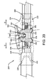
- a shoulder 228, referenced in FIGURES 20 and 29 may limit the distance the second pole 204 can be inserted into the housing 220.
- the first pole 202 may, depending on the amount of extension, extend through both ends of the first housing portion 222.
- the second housing portion 222 may attach to the second housing portion 224 to enclose the poles.
- the first housing portion 222 has a pair of convex features 230 (referenced in FIGURE 29 ) that are received in matching concave features 232 (referenced in FIGURE 22 ) formed on the second housing portion 224.
- One or more connectors 238, four shown, may be received in connector holes and used to secure the housing portions 222, 224 together.
- the first and second contact devices 300, 350 may be adjusted between a use condition where they contact the first pole 202 to hold the first pole 202 in a longitudinally fixed position with respect to the second pole 204 and an adjustment condition where the contact devices 300, 350 do not hold the first pole 202 in a longitudinally fixed position with respect to the second pole 204.
- the first pole 202 is longitudinally moveable with respect to the second pole 204 to adjust the overall length of both poles.
- FIGURES 20 and 21 show the contact devices 300, 350 in the use condition where the angles A, B between the longitudinal axis of the first pole 202 and the radii of the contact devices 300, 350, respectively, are acute (less than 90 degrees) and thus the contact devices 300, 350 contact the first pole 202 to prevent relative movement of the first pole 202 with respect to the second pole 204.
- the adjustment condition is not shown but it is achieved when the angles A, B are right angles (90 degrees) or approximately right angles.
- right angle A is achieved by moving the top portion of the contact device 300 in direction C
- right angle B is achieved by moving the top portion of the contact device 350 in direction D.
- direction C is opposite to direction D.
- the angles A, B are right angles the contact devices 300, 350 do not contact the first pole 202 or only slightly contact the first pole 202 so that the first pole 202 is longitudinally moveable with respect to the second pole 204.
- the contact devices 300, 350 may each have a pair of arms 302, 302 that receive the first pole 202.
- the contact devices 300, 350 may be supported to the housing 220 and may be movable with respect to the housing 220 between the use condition and the adjustment condition.
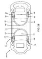
- the first housing portion 222 may have a pair of housing slots 234 (referenced in FIGURES 20 and 28 ) that receive the contact devices 300, 350 and that permit the contact devices 300, 350 to pivot therein between the use condition and the adjustment condition.
- the second housing portion 224 may also have a pair of housing slots 236 (referenced in FIGURE 21 ) that receive the contact devices 300, 350 and that permit the movement of the contact devices 300, 350.
- the contact devices 300, 350 may be ring shaped and may be identical in size and shape. This makes it easy to supply and install the contact devices 300, 350.
- biasing devices 310, 360 may be used to exert a biasing force to bias the contact devices 300, 350, respectively, toward a desired position.
- the biasing devices 310, 360 bias the contact devices 300, 350 toward contact with the first pole 202 and thus bias the contact devices 300, 350 into the use condition.
- the biasing device 310 thus biases the top of contact device 300 in direction D and the biasing device 360 thus biases the top of contact device 350 in direction C.
- the biasing devices 310, 360 are torsion springs each having a pair of coils 312, 362 connected together by mid-sections 314, 364.
- the coils 312, 362 may be received around bushings 316, 366 mounted to the housing 220.
- the mid-sections 314, 364 may be curved to match the contact devices 300, 350 to increase the contact between the mid-sections 314, 364 and the contact devices 300, 350. Portions of the mid-sections 314, 364 may be received within the housing slots 236, as shown.
- the levers 400, 450 may be used to cause the contact devices 300, 350 to move between the use condition and the adjustment condition. While the levers 400, 450 can be of any type and size chosen with the sound judgment of a person of skill in the art, for the embodiment shown each lever 400, 450 is supported to the housing 220 and is moveable with respect to the housing 220. In a specific embodiment, the levers 400, 450 may pivot with respect to the housing 220. Lever 400 may have first and second contact surfaces 402, 404 and may pivot about pivot pin 406 that is received in lever opening 408. Lever 450 may similarly have first and second contact surfaces 452, 454 and may pivot about pivot pin 456 that is received in lever opening 458.
- the levers 400, 450 may be supported to the housing 220 using lever support device 460.
- Lever support device 460 may have a pair of lever support openings 462, 462 that receive the pivot pins 406, 456 and a lever support aperture 464 (referenced in FIGURE 25 ) through which the levers 400, 450 extend.
- Lever support device 460 may also have a lever support channel 466 used as described below.
- the lever support device 460 may be received, such as with an interference fit, within an opening formed in the second housing portion 224.
- the trigger 500 may be moved by a user to cause the first and second levers 400, 450 to move with respect to the housing 220 to cause the first and second contact devices 300, 350 to move with respect to the housing 220 between the use condition and the adjustment condition.
- the trigger 500 may be supported to the housing 220 and moveable with respect to the housing 220 in any manner chosen with the sound judgment of a person of skill in the art to cause the levers 400, 450 to move as just described.
- the trigger may pivot with respect to the housing about pivot pin 502 that may be received in a trigger opening 504 (referenced in FIGURE 22 ) formed in the trigger 500 and in a housing aperture 240 (also referenced in FIGURE 22 ) formed in the second housing portion 224.
- the trigger 500 may have a lever contact device 506 that may be positioned within the lever support channel 466 and used to contact the levers 400, 450.
- the extendable pole mechanism 200 Because of the biasing forces of the biasing devices 310, 360, the contact devices 300, 350 are biased into the use condition, shown in FIGURES 18-21 .
- the user can use the poles 202, 204 that are attached to the extendable pole mechanism 200 in a relatively longitudinally fixed position which is appropriate, for example, when painting. If the user desires to change the relative positions of the poles 202, 204, and thus the overall length of both poles the user may adjust the extendable pole mechanism 200 into the adjustment condition. This can be accomplished simply by applying a manual force, such as with the user's thumb, onto the outer surface of the trigger 500.
- This manual force causes the trigger 500 to pivot about pivot pin 502 so that the lever contact device 506 moves (downward in the figures) in lever support channel 466.
- This movement causes the lever contact device 506 to apply a force to the second contact surfaces 404, 454 of the levers 400, 450 which causes the levers 400, 450 to pivot about respective pivot pins 406, 456 in directions E and F as shown in FIGURE 26 .
- the levers 400, 450 pivot in opposite directions.
- their first contact surfaces 402, 452 contact and apply a force to the contact devices 300, 350, respectively.
- This force on the contact devices 300, 350 overcomes the biasing forces of the biasing devices 310, 360 and moves the contact devices 300, 350 into positions where angles A, B, referenced in FIGURE 20 , are right angles or approximately right angles. In this position, the contact devices 300, 350 do not contact or only slightly contact the first pole 202. As a result, the first pole 202 can be easily longitudinally moved with respect to the second pole 204 to adjust the overall length of both poles. The user may be able to make this overall pole length adjustment using only one hand where the thumb (or other finger) on the one hand maintains a force on the trigger 500. Once the desired overall pole length has been achieved, the user need only remove the manual force from the trigger 500. Once this manual force is removed, the biasing forces of the biasing devices 310, 360 force the contact devices 300, 350 into the use condition where the poles 202, 204 are placed in a longitudinally fixed position.
Landscapes
- Engineering & Computer Science (AREA)
- Mechanical Engineering (AREA)
- Telephone Set Structure (AREA)
- Mutual Connection Of Rods And Tubes (AREA)
- Coating Apparatus (AREA)
- Spray Control Apparatus (AREA)
Abstract
Description
- This application is a continuation-in-part of
U.S. Patent Application Serial No. 13/834,879 filed March 15, 2013 - This invention is in the field of methods and apparatuses for extending and contracting the length of poles used with paint related accessories and more specifically to methods and apparatuses for an extendable pole mechanism that is easily adjusted between a use condition and an adjustment condition with one hand.
- It is well known in the paint industry to provide adjustable length poles that are designed to connect to and disconnect from paint accessories. A painter, for example, requires the pole holding a paint roller to be at a relatively shorter length when painting a surface at waist height but to be at a relatively longer length when painting a surface far above his/her head. Known adjustable length poles, however, have disadvantages.
- One disadvantage to known adjustable length poles is that they are difficult and time consuming to use. Some, for example, require two hands to adjust. Another disadvantage is that they easily come "loose" from their setting, causing the poles to change their length when such change is not desirable. Yet another disadvantage is that many adjustable length poles are only adjustable in discrete length increments. Still another disadvantage is that known adjustable length poles quickly wear out, increasing costs.
- What is needed, then, is an extendable pole mechanism that eliminates or reduces the disadvantages just described. Painters would benefit from using an extendable pole mechanism that is durable, remains in its setting, provides infinite length adjustment, and can be easily operated with one hand.
- According to one embodiment of this invention, an extendable pole mechanism may be used with a first associated pole that is longitudinally movable with respect to a second associated pole to adjust the overall length of both poles. The extendable pole mechanism may comprise: a housing that receives the first and second associated poles; a first contact device that: (1) is supported to the housing; (2) is moveable with respect to the housing; and, (3) comprises first and second arms that receive the first associated pole; a second contact device that: (1) is supported to the housing; (2) is moveable with respect to the housing; and, (3) comprises first and second arms that receive the first associated pole; a first lever that is: (1) is supported to the housing; and, (2) is moveable with respect to the housing; a second lever that is: (1) is supported to the housing; and, (2) is moveable with respect to the housing; and, a trigger that is: (1) is supported to the housing; and, (2) is moveable with respect to the housing. The extendable pole mechanism may be adjustable by moving the trigger with respect to the housing to cause the first and second levers to move with respect to the housing to cause the first and second contact devices to move with respect to the housing between: (1) a use condition where the first associated pole is held by contact with the first and second contact devices in a longitudinally fixed position with respect to the second associated pole; and, (2) an adjustment condition where: (a) the first associated pole is not held by contact with the first and second contact devices in a longitudinally fixed position with respect to the second associated pole; and, (b) the first associated pole is longitudinally moveable with respect to the second associated pole. A first biasing device may exert a first biasing force that biases the first contact device toward contact with the first associated pole. A second biasing device may exert a second biasing force that biases the second contact device toward contact with the first associated pole.
- According to another embodiment of this invention, an extendable pole mechanism may be used with a first associated pole that is longitudinally movable with respect to a second associated pole to adjust the overall length of both poles. The extendable pole mechanism may comprise: a housing that receives the first and second associated poles; a first contact device that: (1) is supported to the housing; and, (2) is moveable with respect to the housing; a second contact device that: (1) is supported to the housing; and, (2) is moveable with respect to the housing; a first lever that is: (1) is supported to the housing; and, (2) is moveable with respect to the housing; a second lever that is: (1) is supported to the housing; and, (2) is moveable with respect to the housing; and, a trigger that is: (1) is supported to the housing; and, (2) is moveable with respect to the housing. The extendable pole mechanism may be adjustable by moving the trigger with respect to the housing to cause the first and second levers to move with respect to the housing to cause the first and second contact devices to move with respect to the housing between: (1) a use condition where the first associated pole is held by contact with the first and second contact devices in a longitudinally fixed position with respect to the second associated pole; and, (2) an adjustment condition where: (a) the first associated pole is not held by contact with the first and second contact devices in a longitudinally fixed position with respect to the second associated pole; and, (b) the first associated pole is longitudinally moveable with respect to the second associated pole.
- According to yet another embodiment of this invention, a method may comprise the steps of: (A) providing an extendable pole mechanism for use with a first pole that is longitudinally movable with respect to a second pole, the extendable pole mechanism comprising: (1) a housing that receives the first and second poles; (2) a first contact device that: (a) is supported to the housing; and, (b) is moveable with respect to the housing; (3) a second contact device that: (a) is supported to the housing; and, (b) is moveable with respect to the housing; (4) a first lever that is: (a) is supported to the housing; and, (b) is moveable with respect to the housing; (5) a second lever that is: (a) is supported to the housing; and, (b) is moveable with respect to the housing; and, (6) a trigger that is: (a) is supported to the housing; and, (b) is moveable with respect to the housing; and, (B) adjusting the extendable pole mechanism by moving the trigger with respect to the housing to cause the first and second levers to move with respect to the housing to cause the first and second contact devices to move with respect to the housing from: (1) a use condition where the first pole is held by contact with the first and second contact devices in a longitudinally fixed position with respect to the second pole; and, (2) an adjustment condition where: (a) the first pole is not held by contact with the first and second contact devices in a longitudinally fixed position with respect to the second pole; and, (b) the first pole is longitudinally moveable with respect to the second pole to adjust the overall length of both poles.
- Numerous benefits and advantages of this invention will become apparent to those skilled in the art to which it pertains upon reading and understanding of the following detailed specification.
- The invention may take physical form in certain parts and arrangement of parts, embodiments of which will be described in detail in this specification and illustrated in the accompanying drawings which form a part hereof and wherein:
-
FIGURE 1 is a side assembly view of an extendable pole mechanism according to some embodiments of this invention. -
FIGURE 2 is a side view of a first housing portion. -
FIGURE 3 is a bottom view of the first housing portion shown inFIGURE 2 . -
FIGURE 4 is a side view of a second housing portion. -
FIGURE 5 is a top view of the second housing portion shown inFIGURE 4 . -
FIGURE 6 is a perspective view of a trigger. -
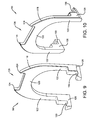
FIGURE 7 is a first side perspective view of a cam lever. -
FIGURE 8 is a second side perspective view of the cam lever shown inFIGURE 7 . -
FIGURE 9 is a first side perspective view of a cam holder. -
FIGURE 10 is a second side perspective view of the cam holder shown inFIGURE 9 . -
FIGURE 11 is a top perspective view of a push member. -
FIGURE 12 is a bottom perspective view of the push member shown inFIGURE 11 . -
FIGURE 13 is a top view of the push member shown inFIGURE 11 . -
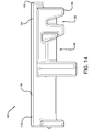
FIGURE 14 is a side view of the push member shown inFIGURE 11 . -
FIGURE 15 is a bottom perspective view of the extendable pole mechanism in a use condition with the first pole and a portion of the housing hidden. -
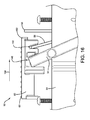
FIGURE 16 is a side view of the extendable pole mechanism in an adjustment condition with the first pole and a portion of the housing hidden. -
FIGURE 17 is a side perspective view of the extendable pole mechanism connected to a point roller according to some embodiments of this invention. -
FIGURE 18 is a perspective view of an extendable pole mechanism according to some embodiments of this invention with the full length of poles not shown for simplicity. -
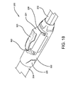
FIGURE 19 is a side view of the extendable pole mechanism shown inFIGURE 18 . -
FIGURE 20 is a view similar to that shown inFIGURE 19 but with components shown as being transparent so that the internal workings can be visualized. -
FIGURE 21 is a close up view of a portion of the extendable pole mechanism shown inFIGURE 20 . -
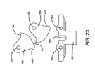
FIGURE 22 is an assembly view of some components of the extendable pole mechanism shown inFIGURE 18 . -
FIGURE 23 is a close up view of some of the components shown inFIGURE 22 . -
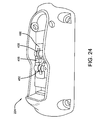
FIGURE 24 is a perspective side view of the second housing portion. -
FIGURE 25 is a top view of a lever support device. -
FIGURE 26 is a side view of the lever support device shown inFIGURE 25 . -
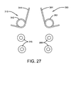
FIGURE 27 is an assembly view of some components of the extendable pole mechanism shown inFIGURE 18 . -
FIGURE 28 is a top view of the first housing portion with components removed so the biasing devices can be seen. -
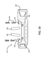
FIGURE 29 is an assembly view of some components of the extendable pole mechanism shown inFIGURE 18 . -
FIGURE 30 is a side perspective view of a contact device. - Referring now to the drawings wherein the showings are for purposes of illustrating embodiments of the invention only and not for purposes of limiting the same, and wherein like reference numerals are understood to refer to like components,
FIGURES 1 and17 show a pair ofpoles extendable pole mechanism 50 of this invention. While theextendable pole mechanism 50 is ideally suited for use with paint accessories and the like, such as thepaint roller 20 shown inFIGURE 17 , it is not limited to that application.Pole 10 may have an outside diameter that is received within an inside diameter ofpole 12. As a result,pole 10 is slideable within pole 12 (and with respect to pole 12) infirst direction 14 andsecond direction 16. Whenpole 10 is slid indirection 14, the overall length of both poles is decreased. Whenpole 10 is slid indirection 16, the overall length of both poles is increased. Thus, a user can adjust the overall length of the poles by slidingpole 10 with respect topole 12.Pole 10 may have aconnection site 18 to which a paint accessory, such aspaint roller 20, can be attached.Pole 12 and/or the housing may serve as a handle for the user. In one specific embodiment,pole 10 is made of aluminum andpole 12 is made of fiberglass to provide good performance. - With reference now to
FIGURE 1 , theextendable pole mechanism 50 may be adjusted between a use condition, wherepole 10 is held in a longitudinally fixed position with respect topole 12, and an adjustment condition, wherepole 10 can be slide longitudinally with respect topole 12 so that the overall length can be changed. Theextendable pole mechanism 50 may include ahousing 52, atrigger 54, acam lever 56, acam holder 58, apush member 60, and abiasing device 62, which may be a spring, as shown. These components will now be described in more detail. - With reference now to
FIGURES 1-5 , thehousing 52 may have first andsecond portions poles connectors 68 received inopenings 70. While six threaded connectors are used in the embodiment shown, the number and type can be any chosen with the sound judgment of a person of skill in the art. Thefirst housing portion 64 may includeshaft receiving grooves 72, anexternal protection ring 74, internallateral extensions 76 and an internallongitudinal extension 78. Agroove 80 may be formed between some of thelateral extensions 76, as shown. Theexternal protection ring 74 shown only extends a small amount around the external surface of theportion 64. Thesecond housing portion 66 may includeshaft receiving grooves 82 and anexternal protection ring 84 that may extend all the way around the external surface of theportion 66, as shown. Thesecond housing portion 66 may have internallateral extensions 86 and pole contact surfaces 88.Extensions 90 may definegrooves 92 between them, as shown. The purposes for these components will be discussed below. - With reference now to
FIGURES 1 and6 , thetrigger 54 may have abody 94 having a mid-section 96 and a pair orarms body 94 is C-shaped. A pair ofhands arms hands inner surfaces 104, as shown. A pair ofshaft portions arms hands shaft portions trigger 54 may be formed of any material chosen with the sound judgment of a person of skill in the art. In one embodiment, thetrigger 54 is made of plastic and in another it is made of a metal. - With reference now to
FIGURES 1 and7-8 , thecam lever 56 may have abody 106 having a mid-section 108 and a pair ofarms body 106 is C-shaped. First andsecond surfaces first surface 112 may extend above thesecond surface 114 and may be curved, as shown, to match the outside diameter ofpole 10. Shoulder surfaces 116, 116, may be formed at proximal ends of thearms arms cam lever 56 may be formed of any material chosen with the sound judgment of a person of skill in the art. - With reference now to
FIGURES 1 and9-10 , thecam holder 58 may have abody 118 having a mid-section 120 and a pair orarms body 118 is C-shaped. A pair ofsurfaces groove 126 on the external surface of the mid-section 120, as shown.Hands arms hands cam holder 58 may be formed of any material chosen with the sound judgment of a person of skill in the art. - With reference now to
FIGURES 1 and11-14 , thepush member 60 may have first and second ends 132, 134, a top 136 and a bottom 138. Achamber 140 may be provided on the top 136,first end 132 and may receive thebiasing device 62 shown inFIGURE 1 . Thechamber 140 may be defined by awall 142 at one end and may have a generally cylindrical shape, as shown. Aslot 144 may be formed in a surface defining the bottom of thechamber 140 and may extend from thefirst end 132 toward the mid-section of thepush member 60. Pole contact surfaces 146, 146 may extend from the bottom 138 and may be curved, as shown, to match the outside diameter ofpole 10.Grooves push member 60 and agroove 150 may be formed on thebottom 138 of thepush member 60, as shown. Thesecond end 134 may have anextension 152. Thepush member 60 may be formed of any material chosen with the sound judgment of a person of skill in the art. - The assembly of the
extendable pole mechanism 50 will now be described. Thepoles housing portions FIGURES 1 ,15 and17 . Thepush member 60 may be positioned primarily within thehousing portion 64, betweenlateral extensions 76, as shown inFIGURE 15 , and theslot 144 may receive theextension 78. The pole contact surfaces 146 may receive the outer surface of thepole 10, thoughpole 10 is hidden inFIGURES 15 and16 . With reference toFIGURES 2-6 and15-16 , theshaft portions 102 of thetrigger 54 may be received in theshaft receiving grooves respective housing portions hands 100 of thetrigger 54, seeFIGURE 6 , may be positioned within thegrooves 148 formed on thepush member 60, as seen inFIGURE 16 . Thepole 10 may be received between thearms 98 of thetrigger 54 and the mid-section 96 andarms 98 of thetrigger 54 may be positioned outside thehousing 52. Thecam holder 58 may be positioned within thehousing 52 with the mid-section 120, seeFIGURES 9-10 , received in thegroove 80, seeFIGURE 3 , formed in thefirst housing portion 64. This is shown inFIGURE 15 . Thepole 10 may be received between thearms 122 of thecam holder 58. Thehands 128 of thecam holder 58, seeFIGURES 9-10 , may be received in thegrooves FIGURE 5 , formed in thesecond housing portion 66. Thecam holder 58 thus may be held substantially fixed throughout the operation of theextendable pole mechanism 50. This is shown inFIGURES 15 and16 . Thecam lever 56 may be positioned within thehousing 52 with the distal ends of thearms FIGURES 7-8 , received in thegroove 150 formed on thepush member 60, as shown inFIGURE 16 . Thepole 10 may be received between thearms 110 of thecam lever 56. The shoulder surfaces 116, 116, seeFIGURES 7-8 , may be received on the contact surfaces 130 on thecam holder 58, seeFIGURES 9-10 and15 . - With the
extendable pole mechanism 50 assembled as described above, its operation will now be described.FIGURE 15 shows theextendable pole mechanism 50 in the use condition wherepole 10 is held in a longitudinally fixed position with respect topole 12. This is generally the preferred condition for using the poles while painting, for example. In this use condition, thepole 10 is received between thearms 98 of thetrigger 54, thearms 110 of thecam lever 56, and thearms 122 of thecam holder 58. Note that thearms 98 of thetrigger 54, thearms 110 of thecam lever 56, and thearms 122 of thecam holder 58 are substantially parallel with each other and substantially perpendicular to the longitudinal axes of thepoles extension 152, seeFIGURES 13-14 and16 , of thepush member 60 may be received in thegroove 126, seeFIGURES 9-10 , in thecam holder 58. In this use condition, the bottom of thepole 10 rests securely on thefirst surface 112 of thecam lever 56, seeFIGURES 7-8 . - To adjust the
extendable pole mechanism 50 into the adjustment condition, shown inFIGURES 16 and17 , all the user has to do is move the mid-section of thetrigger 54 indirection 154 shown inFIGURE 15 . This can easily be done with a single finger, perhaps the user's thumb. This motion causes thetrigger 54 to pivot about itsshaft portions 102, seeFIGURE 6 . As thetrigger 54 is pivoted, thehands 100 within thegrooves 148 of thepush member 60 push/slide thepush member 60 indirection 156, shown inFIGURE 15 . As thepush member 60 is moved indirection 156, the biasing force of thespring 62 is overcome as theextension 78 is received farther into theslot 144. Movement of thepush member 60 indirection 156 also causes the distal ends of thearms 110, seeFIGURES 7-8 , which are received ingroove 150 to move indirection 156. As thearms 110 move in this way, the shoulder surfaces 116, seeFIGURES 7-8 , pivot on the contact surfaces 130, seeFIGURES 9-10 , of the cam holder 58 (and thus with respect to the cam holder). This movement of thetrigger 54, and thus thepush member 60 andcam lever 56, may be continued until the adjustment condition shown inFIGURE 16 is achieved. - With the
extendable pole mechanism 50 in the adjustment condition shown inFIGURES 16 and17 , thepole 10 remains between thearms 98 of thetrigger 54, thearms 110 of thecam lever 56, and thearms 122 of thecam holder 58. The arms of thetrigger 54 and thecam lever 56, however, are no longer parallel with the arms of thecam holder 58 and are no longer perpendicular to the longitudinal axes of thepoles pole 10 contacts first andsecond surfaces FIGURES 7-8 , of thecam lever 56 and the pole contact surfaces 88, seeFIGURE 5 , of thesecond housing portion 66. With thecam lever 56 angled in this manner, room for thepole 10 within thehousing 52 is increased, making it very easy to adjust the relative longitudinal positions of thepoles pole 10 with respect topole 12 to change the overall length. In fact, if the user simply aims thepole 10 toward the ground while holding thehousing 52 or thepole 12, gravity will easily cause thepole 10 to slide out of thehousing 52 and pole 12 (indirection 16 inFIGURE 1 ), increasing the overall length. Similarly, if the user simply aims thepole 10 toward the sky while holding thehousing 52 or thepole 12, gravity will easily cause thepole 10 to slide into thehousing 52 and pole 12 (indirection 14 inFIGURE 1 ), decreasing the overall length. - To adjust the
extendable pole mechanism 50 from the adjustment condition shown inFIGURES 16 and17 to the use condition shown inFIGURE 15 , all the user has to do is release thetrigger 54. When thetrigger 54 is released, the biasing force of thespring 62 will force/slide thepush member 60 indirection 158, shown inFIGURES 15 and16 until the components return to the relative positions shown inFIGURE 15 . - With reference now to
FIGURES 18-20 and29 , anextendable pole mechanism 200 according to other embodiments is disclosed. Theextendable pole mechanism 200 may be used with a first pole 202 (only a portion shown) that is longitudinally movable with respect to a second pole 204 (only a portion shown) to adjust the overall length of both poles. Thesecond pole 204 may have an outer diameter that is greater than the outer diameter of thefirst pole 202 and may have a longitudinally extending opening that receives thefirst pole 202. As a result, thefirst pole 202 may be moved longitudinally within thesecond pole 204. Theextendable pole mechanism 200 may include ahousing 220, first andsecond contact devices second levers trigger 500. These components and their operation will be described below. - With reference now to
FIGURES 18-22 and29 , while thehousing 220 used with this invention can be of any style and size chosen with the sound judgment of a person of skill in the art, for the embodiment shown, thehousing 220 may comprise afirst housing portion 222 and asecond housing portion 224. Thefirst housing portion 222 may have alongitudinally extending opening 226 that receives the first andsecond poles shoulder 228, referenced inFIGURES 20 and29 , may limit the distance thesecond pole 204 can be inserted into thehousing 220. Thefirst pole 202 may, depending on the amount of extension, extend through both ends of thefirst housing portion 222. Thesecond housing portion 222 may attach to thesecond housing portion 224 to enclose the poles. While this attachment may be any chosen with the sound judgment of a person of skill in the art, for the embodiment shown thefirst housing portion 222 has a pair of convex features 230 (referenced inFIGURE 29 ) that are received in matching concave features 232 (referenced inFIGURE 22 ) formed on thesecond housing portion 224. One ormore connectors 238, four shown, may be received in connector holes and used to secure thehousing portions - With reference now to
FIGURES 19-21 , the first andsecond contact devices first pole 202 to hold thefirst pole 202 in a longitudinally fixed position with respect to thesecond pole 204 and an adjustment condition where thecontact devices first pole 202 in a longitudinally fixed position with respect to thesecond pole 204. As a result, in the adjustment condition thefirst pole 202 is longitudinally moveable with respect to thesecond pole 204 to adjust the overall length of both poles.FIGURES 20 and21 show thecontact devices first pole 202 and the radii of thecontact devices contact devices first pole 202 to prevent relative movement of thefirst pole 202 with respect to thesecond pole 204. The adjustment condition is not shown but it is achieved when the angles A, B are right angles (90 degrees) or approximately right angles. For the embodiment shown, right angle A is achieved by moving the top portion of thecontact device 300 in direction C and right angle B is achieved by moving the top portion of thecontact device 350 in direction D. For the embodiment shown, direction C is opposite to direction D. When the angles A, B are right angles thecontact devices first pole 202 or only slightly contact thefirst pole 202 so that thefirst pole 202 is longitudinally moveable with respect to thesecond pole 204. - With reference now to
FIGURES 20-21 and29-30 , thecontact devices arms first pole 202. Thecontact devices housing 220 and may be movable with respect to thehousing 220 between the use condition and the adjustment condition. In one specific embodiment, thefirst housing portion 222 may have a pair of housing slots 234 (referenced inFIGURES 20 and28 ) that receive thecontact devices contact devices second housing portion 224 may also have a pair of housing slots 236 (referenced inFIGURE 21 ) that receive thecontact devices contact devices FIGURES 29 and30 , thecontact devices contact devices - With reference now to
FIGURES 20-21 and27-28 , for the embodiment shown, biasingdevices contact devices devices contact devices first pole 202 and thus bias thecontact devices FIGURE 20 , thebiasing device 310 thus biases the top ofcontact device 300 in direction D and thebiasing device 360 thus biases the top ofcontact device 350 in direction C. While the biasing devices used can be of any type chosen with the sound judgment of a person of skill in the art, for the embodiment shown thebiasing devices coils mid-sections coils bushings housing 220. Themid-sections contact devices mid-sections contact devices mid-sections housing slots 236, as shown. - With reference now to
FIGURES 20-26 , thelevers contact devices levers lever housing 220 and is moveable with respect to thehousing 220. In a specific embodiment, thelevers housing 220.Lever 400 may have first and second contact surfaces 402, 404 and may pivot aboutpivot pin 406 that is received inlever opening 408.Lever 450 may similarly have first and second contact surfaces 452, 454 and may pivot aboutpivot pin 456 that is received inlever opening 458. Thelevers housing 220 usinglever support device 460.Lever support device 460 may have a pair oflever support openings FIGURE 25 ) through which thelevers Lever support device 460 may also have alever support channel 466 used as described below. Thelever support device 460 may be received, such as with an interference fit, within an opening formed in thesecond housing portion 224. - With reference now to
FIGURES 18-22 , thetrigger 500 may be moved by a user to cause the first andsecond levers housing 220 to cause the first andsecond contact devices housing 220 between the use condition and the adjustment condition. Thetrigger 500 may be supported to thehousing 220 and moveable with respect to thehousing 220 in any manner chosen with the sound judgment of a person of skill in the art to cause thelevers pivot pin 502 that may be received in a trigger opening 504 (referenced inFIGURE 22 ) formed in thetrigger 500 and in a housing aperture 240 (also referenced inFIGURE 22 ) formed in thesecond housing portion 224. Thetrigger 500 may have alever contact device 506 that may be positioned within thelever support channel 466 and used to contact thelevers - With reference now to all the FIGURES, operation of the
extendable pole mechanism 200 will now be described. Because of the biasing forces of the biasingdevices contact devices FIGURES 18-21 . As a result, the user can use thepoles extendable pole mechanism 200 in a relatively longitudinally fixed position which is appropriate, for example, when painting. If the user desires to change the relative positions of thepoles extendable pole mechanism 200 into the adjustment condition. This can be accomplished simply by applying a manual force, such as with the user's thumb, onto the outer surface of thetrigger 500. This manual force causes thetrigger 500 to pivot aboutpivot pin 502 so that thelever contact device 506 moves (downward in the figures) inlever support channel 466. This movement causes thelever contact device 506 to apply a force to the second contact surfaces 404, 454 of thelevers levers FIGURE 26 . Note that in this embodiment thelevers levers contact devices contact devices devices contact devices FIGURE 20 , are right angles or approximately right angles. In this position, thecontact devices first pole 202. As a result, thefirst pole 202 can be easily longitudinally moved with respect to thesecond pole 204 to adjust the overall length of both poles. The user may be able to make this overall pole length adjustment using only one hand where the thumb (or other finger) on the one hand maintains a force on thetrigger 500. Once the desired overall pole length has been achieved, the user need only remove the manual force from thetrigger 500. Once this manual force is removed, the biasing forces of the biasingdevices contact devices poles - Numerous embodiments have been described herein. It will be apparent to those skilled in the art that the above methods and apparatuses may incorporate changes and modifications without departing from the general scope of this invention. It is intended to include all such modifications and alterations in so far as they come within the scope of the appended claims or the equivalents thereof.
Claims (20)
- An extendable pole mechanism for use with a first associated pole that is longitudinally movable with respect to a second associated pole to adjust the overall length of both poles, the extendable pole mechanism comprising:a housing that receives the first and second associated poles;a first contact device that: (1) is supported to the housing; and, (2) is moveable with respect to the housing;a second contact device that: (1) is supported to the housing; and, (2) is moveable with respect to the housing;a first lever that is: (1) is supported to the housing; and, (2) is moveable with respect to the housing;a second lever that is: (1) is supported to the housing; and, (2) is moveable with respect to the housing;a trigger that is: (1) is supported to the housing; and, (2) is moveable with respect to the housing; and,wherein the extendable pole mechanism is adjustable by moving the trigger with respect to the housing to cause the first and second levers to move with respect to the housing to cause the first and second contact devices to move with respect to the housing between: (1) a use condition where the first associated pole is held by contact with the first and second contact devices in a longitudinally fixed position with respect to the second associated pole; and, (2) an adjustment condition where: (a) the first associated pole is not held by contact with the first and second contact devices in a longitudinally fixed position with respect to the second associated pole; and, (b) the first associated pole is longitudinally moveable with respect to the second associated pole.
- The extendable pole mechanism of claim 1 further comprising:a first biasing device that exerts a first biasing force that biases the first contact device toward contact with the first associated pole; and,a second biasing device that exerts a second biasing force that biases the second contact device toward contact with the first associated pole.
- The extendable pole mechanism of claim 2 wherein:the first biasing device biases the first contact device in a first direction; and,the second biasing device biases the second contact device in a second direction that is substantially opposite the first direction.
- The extendable pole mechanism of claim 2 wherein:the first biasing device is a first spring comprising first and second coils connected together by a mid-section;the second biasing device is a second spring comprising first and second coils connected together by a mid-section;the mid-section of the first spring contacts the first biasing device to bias the first contact device; and,the mid-section of the second spring contacts the second biasing device to bias the second contact device.
- The extendable pole mechanism of claim 1 wherein:the first lever pivots in a first direction with respect to the housing to cause the first contact device to move with respect to the housing out of contact with the first associated pole; and,the second lever pivots in a second direction with respect to the housing that is substantially opposite to the first direction to cause the second contact device to move with respect to the housing out of contact with the first associated pole.
- The extendable pole mechanism of claim 1 wherein:the first lever: (1) comprises first and second contact surfaces; and, (2) is pivotal with respect to the housing;the second lever: (1) comprises first and second contact surfaces; and, (2) is pivotal with respect to the housing;the trigger: (1) comprises a lever contact device; and, (2) is pivotal with respect to the housing; and,wherein the extendable pole mechanism is adjustable by pivoting the trigger with respect to the housing to cause the lever contact device to contact the first contact surfaces of the first and second levers to cause the second contact surfaces of the first and second levers to contact the first and second contact devices, respectively, to cause the first and second contact devices to move with respect to the housing out of contact with the first associated pole.
- The extendable pole mechanism of claim 1 wherein:the housing comprises first and second housing slots;the first contact device: (1) comprises first and second arms; (2) is positioned within the first housing slot;the second contact device: (1) comprises first and second arms; (2) is positioned within the second housing slot; and,the first associated pole is positioned between the first and second arms of the first contact device and the first and second arms of the second contact device.
- An extendable pole mechanism for use with a first associated pole that is longitudinally movable with respect to a second associated pole to adjust the overall length of both poles, the extendable pole mechanism comprising:a housing that receives the first and second associated poles;a first contact device that: (1) is supported to the housing; (2) is moveable with respect to the housing; and, (3) comprises first and second arms that receive the first associated pole;a second contact device that: (1) is supported to the housing; (2) is moveable with respect to the housing; and, (3) comprises first and second arms that receive the first associated pole;a first lever that is: (1) is supported to the housing; and, (2) is moveable with respect to the housing;a second lever that is: (1) is supported to the housing; and, (2) is moveable with respect to the housing;a trigger that is: (1) is supported to the housing; and, (2) is moveable with respect to the housing;wherein the extendable pole mechanism is adjustable by moving the trigger with respect to the housing to cause the first and second levers to move with respect to the housing to cause the first and second contact devices to move with respect to the housing between: (1) a use condition where the first associated pole is held by contact with the first and second contact devices in a longitudinally fixed position with respect to the second associated pole; and, (2) an adjustment condition where: (a) the first associated pole is not held by contact with the first and second contact devices in a longitudinally fixed position with respect to the second associated pole; and, (b) the first associated pole is longitudinally moveable with respect to the second associated pole;a first biasing device that exerts a first biasing force that biases the first contact device toward contact with the first associated pole; and,a second biasing device that exerts a second biasing force that biases the second contact device toward contact with the first associated pole.
- The extendable pole mechanism of claim 8 wherein:the first biasing device biases the first contact device in a first direction; and,the second biasing device biases the second contact device in a second direction that is substantially opposite the first direction.
- The extendable pole mechanism of claim 9 wherein:the first biasing device is a first spring comprising first and second coils connected together by a mid-section;the second biasing device is a second spring comprising first and second coils connected together by a mid-section;the mid-section of the first spring contacts the first biasing device to bias the first contact device; and,the mid-section of the second spring contacts the second biasing device to bias the second contact device.
- The extendable pole mechanism of claim 8 wherein:the first lever pivots in a first direction with respect to the housing to cause the first contact device to move with respect to the housing out of contact with the first associated pole; and,the second lever pivots in a second direction with respect to the housing that is substantially opposite to the first direction to cause the second contact device to move with respect to the housing out of contact with the first associated pole.
- The extendable pole mechanism of claim 8 wherein:the first lever: (1) comprises first and second contact surfaces; and, (2) is pivotal with respect to the housing;the second lever: (1) comprises first and second contact surfaces; and, (2) is pivotal with respect to the housing;the trigger: (1) comprises a lever contact device; and, (2) is pivotal with respect to the housing; and,wherein the extendable pole mechanism is adjustable by pivoting the trigger with respect to the housing to cause the lever contact device to contact the first contact surfaces of the first and second levers to cause the second contact surfaces of the first and second levers to contact the first and second contact devices, respectively, to cause the first and second contact devices to move with respect to the housing out of contact with the first associated pole.
- The extendable pole mechanism of claim 8 wherein:the housing comprises first and second housing slots;the first contact device: (1) is ring shaped; (2) has a first portion that is positioned within the first housing slot; and, (3) has a second portion that is contacted by the first biasing device; and,the second contact device: (1) is ring shaped; (2) has a first portion that is positioned within the second housing slot; and, (3) has a second portion that is contacted by the second biasing device.
- A method comprising the steps of:(A) providing an extendable pole mechanism for use with a first pole that is longitudinally movable with respect to a second pole, the extendable pole mechanism comprising: (1) a housing that receives the first and second poles; (2) a first contact device that: (a) is supported to the housing; and, (b) is moveable with respect to the housing; (3) a second contact device that: (a) is supported to the housing; and, (b) is moveable with respect to the housing; (4) a first lever that is: (a) is supported to the housing; and, (b) is moveable with respect to the housing; (5) a second lever that is: (a) is supported to the housing; and, (b) is moveable with respect to the housing; and, (6) a trigger that is: (a) is supported to the housing; and, (b) is moveable with respect to the housing; and,(B) adjusting the extendable pole mechanism by moving the trigger with respect to the housing to cause the first and second levers to move with respect to the housing to cause the first and second contact devices to move with respect to the housing from: (1) a use condition where the first pole is held by contact with the first and second contact devices in a longitudinally fixed position with respect to the second pole; and, (2) an adjustment condition where: (a) the first pole is not held by contact with the first and second contact devices in a longitudinally fixed position with respect to the second pole; and, (b) the first pole is longitudinally moveable with respect to the second pole to adjust the overall length of both poles.
- The method of claim 14 wherein:step (A) comprises the steps of: providing a first biasing device that exerts a first biasing force that biases the first contact device toward contact with the first pole; and, providing a second biasing device that exerts a second biasing force that biases the second contact device toward contact with the first pole; and,the step of adjusting the extendable pole mechanism from the use condition to the adjustment condition comprises the step of: overcoming the first and second biasing forces.
- The method of claim 15 wherein:the step of biasing the first contact device toward contact with the first pole, comprises the step of biasing the first contact device in a first direction; and,the step of biasing the second contact device toward contact with the second pole, comprises the step of biasing the second contact device in a second direction that is substantially opposite the first direction.
- The method of claim 15 wherein:step (A) comprises the steps of: providing the first biasing device to be a first spring comprising first and second coils connected together by a mid-section; and, providing the second biasing device to be a second spring comprising first and second coils connected together by a mid-section;the step of biasing the first contact device toward contact with the first pole, comprises the step of biasing the first contact device by contacting the first contact device with the mid-section of the first spring; and,the step of biasing the second contact device toward contact with the second pole, comprises the step of biasing the second contact device by contacting the second contact device with the mid-section of the second spring.
- The method of claim 14 wherein the step of adjusting the extendable pole mechanism from the use condition to the adjustment condition comprises the steps of:pivoting the first lever in a first direction with respect to the housing to cause the first contact device to move with respect to the housing; and,pivoting the second lever in a second direction that is substantially opposite the first direction with respect to the housing to cause the second contact device to move with respect to the housing.
- The method of claim 14 wherein:step (A) comprises the steps of: (1) providing the first lever to comprise first and second contact surfaces and to be pivotal with respect to the housing; (2) providing the second lever to comprise first and second contact surfaces and to be pivotal with respect to the housing; and, (3) providing the trigger to comprise a lever contact device and to be pivotal with respect to the housing; and,the step of adjusting the extendable pole mechanism from the use condition to the adjustment condition comprises the step of: pivoting the trigger with respect to the housing to cause the lever contact device to contact the first contact surfaces of the first and second levers to cause the second contact surfaces of the first and second levers to contact the first and second contact devices, respectively, to cause the first and second contact devices to move with respect to the housing out of contact with the first pole.
- The method of claim 14 wherein:step (A) comprises the steps of: (1) providing the housing to comprise first and second housing slots; (2) providing the first contact device to comprise first and second arms that receive the first pole and to be positioned within the first housing slot; and, (3) providing the second contact device to comprise first and second arms that receive the first pole and to be positioned within the second housing slot; and,the step of adjusting the extendable pole mechanism from the use condition to the adjustment condition comprises the step of: pivoting the first and second contact devices about the first and second housing slots, respectively.
Applications Claiming Priority (1)
| Application Number | Priority Date | Filing Date | Title |
|---|---|---|---|
| US14/268,718 US9347472B2 (en) | 2013-03-15 | 2014-05-02 | Extension pole mechanism for paint roller |
Publications (3)
| Publication Number | Publication Date |
|---|---|
| EP2949400A2 true EP2949400A2 (en) | 2015-12-02 |
| EP2949400A3 EP2949400A3 (en) | 2016-08-24 |
| EP2949400B1 EP2949400B1 (en) | 2018-02-21 |
Family
ID=53016569
Family Applications (1)
| Application Number | Title | Priority Date | Filing Date |
|---|---|---|---|
| EP15166144.4A Active EP2949400B1 (en) | 2014-05-02 | 2015-05-01 | Extension pole mechanism for paint roller |
Country Status (3)
| Country | Link |
|---|---|
| EP (1) | EP2949400B1 (en) |
| AU (1) | AU2015202298B2 (en) |
| CA (1) | CA2890389C (en) |
Families Citing this family (2)
| Publication number | Priority date | Publication date | Assignee | Title |
|---|---|---|---|---|
| CN110653102A (en) * | 2019-10-15 | 2020-01-07 | 成都飞机工业(集团)有限责任公司 | Spray gun posture adjusting device free of disassembly |
| US12435745B1 (en) * | 2024-09-20 | 2025-10-07 | Greg A. Miller | Lock mechanism operable to lock an adjusted length of telescopically attached rods |
Family Cites Families (5)
| Publication number | Priority date | Publication date | Assignee | Title |
|---|---|---|---|---|
| US2806723A (en) * | 1955-06-16 | 1957-09-17 | Thomas H Fairclough | Telescopic support device |
| US5595410A (en) * | 1995-02-27 | 1997-01-21 | Chicago Steel Tape Co. | Quick-release locking device for telescoping member |
| FR2827921B1 (en) * | 2001-07-24 | 2007-05-25 | Pascal Guidetti | DEVICE FOR LOCKING TWO TELESCOPIC ELONGATED ELEMENTS |
| DE102009006789B4 (en) * | 2009-01-30 | 2012-09-27 | Cullmann Foto-Audio-Video Gmbh | Telescopic support device with clamping device |
| RU2517240C2 (en) * | 2009-02-11 | 2014-05-27 | Смарт Левел Компани Б.В. | Support element for object and device comprising support element |
-
2015
- 2015-05-01 CA CA2890389A patent/CA2890389C/en active Active
- 2015-05-01 EP EP15166144.4A patent/EP2949400B1/en active Active
- 2015-05-01 AU AU2015202298A patent/AU2015202298B2/en active Active
Non-Patent Citations (1)
| Title |
|---|
| None |
Also Published As
| Publication number | Publication date |
|---|---|
| EP2949400A3 (en) | 2016-08-24 |
| AU2015202298A1 (en) | 2015-11-19 |
| CA2890389C (en) | 2017-10-03 |
| HK1218274A1 (en) | 2017-02-10 |
| AU2015202298B2 (en) | 2017-08-17 |
| EP2949400B1 (en) | 2018-02-21 |
| CA2890389A1 (en) | 2015-11-02 |
Similar Documents
| Publication | Publication Date | Title |
|---|---|---|
| US9347472B2 (en) | Extension pole mechanism for paint roller | |
| CN110180139B (en) | Spring-grip dumb-bell | |
| US2409432A (en) | Intravenous needle holder | |
| KR100760083B1 (en) | Grip | |
| US20120085331A1 (en) | Systems and methods of accessory mounting | |
| CA2890389C (en) | Extension pole mechanism for paint roller | |
| CA2859910C (en) | Pipe painter assembly | |
| US11794328B2 (en) | Angularly adjustable tool connection having threaded connector and clamp-type connector | |
| CN110456855B (en) | Wheel mechanism and control device using the same | |
| US4589164A (en) | Variable tension device with adjustable features for spring rate, initial tension and connection to external parts | |
| CA2981950A1 (en) | Pair of scissors, particularly for cutting hair | |
| US7946070B1 (en) | Shooting stick apparatus | |
| EP2969251B1 (en) | Extension pole mechanism for paint roller | |
| CA2907130C (en) | Extension pole mechanism for paint roller | |
| KR101411815B1 (en) | umbrella holder | |
| HK1218274B (en) | Extension pole mechanism for paint roller | |
| US9664473B2 (en) | Handle for manipulating firearm rod | |
| WO2014151320A1 (en) | Quick fit adjustment mechanism for extension pole system for paint roller | |
| US9500316B2 (en) | System and apparatus for the support of optics | |
| EP2372173A1 (en) | An adjustment device for use in adjusting the length of a telescopic arrangement | |
| US20090064434A1 (en) | Painting tools | |
| US20180193048A1 (en) | Bifurcated forceps | |
| CN223463779U (en) | Angle-adjustable eyelash assist device |
Legal Events
| Date | Code | Title | Description |
|---|---|---|---|
| AK | Designated contracting states |
Kind code of ref document: A2 Designated state(s): AL AT BE BG CH CY CZ DE DK EE ES FI FR GB GR HR HU IE IS IT LI LT LU LV MC MK MT NL NO PL PT RO RS SE SI SK SM TR |
|
| AX | Request for extension of the european patent |
Extension state: BA ME |
|
| PUAI | Public reference made under article 153(3) epc to a published international application that has entered the european phase |
Free format text: ORIGINAL CODE: 0009012 |
|
| PUAL | Search report despatched |
Free format text: ORIGINAL CODE: 0009013 |
|
| AK | Designated contracting states |
Kind code of ref document: A3 Designated state(s): AL AT BE BG CH CY CZ DE DK EE ES FI FR GB GR HR HU IE IS IT LI LT LU LV MC MK MT NL NO PL PT RO RS SE SI SK SM TR |
|
| AX | Request for extension of the european patent |
Extension state: BA ME |
|
| RIC1 | Information provided on ipc code assigned before grant |
Ipc: B25G 1/04 20060101ALI20160718BHEP Ipc: B05B 15/06 20060101AFI20160718BHEP Ipc: F16B 2/24 20060101ALI20160718BHEP Ipc: B05C 17/02 20060101ALI20160718BHEP |
|
| REG | Reference to a national code |
Ref country code: HK Ref legal event code: DE Ref document number: 1218274 Country of ref document: HK |
|
| STAA | Information on the status of an ep patent application or granted ep patent |
Free format text: STATUS: REQUEST FOR EXAMINATION WAS MADE |
|
| 17P | Request for examination filed |
Effective date: 20170224 |
|
| RBV | Designated contracting states (corrected) |
Designated state(s): AL AT BE BG CH CY CZ DE DK EE ES FI FR GB GR HR HU IE IS IT LI LT LU LV MC MK MT NL NO PL PT RO RS SE SI SK SM TR |
|
| GRAP | Despatch of communication of intention to grant a patent |
Free format text: ORIGINAL CODE: EPIDOSNIGR1 |
|
| STAA | Information on the status of an ep patent application or granted ep patent |
Free format text: STATUS: GRANT OF PATENT IS INTENDED |
|
| RIC1 | Information provided on ipc code assigned before grant |
Ipc: B05C 17/02 20060101ALI20170811BHEP Ipc: B05B 15/06 20060101AFI20170811BHEP Ipc: F16B 2/24 20060101ALI20170811BHEP Ipc: B25G 1/04 20060101ALI20170811BHEP |
|
| INTG | Intention to grant announced |
Effective date: 20170829 |
|
| GRAS | Grant fee paid |
Free format text: ORIGINAL CODE: EPIDOSNIGR3 |
|
| GRAA | (expected) grant |
Free format text: ORIGINAL CODE: 0009210 |
|
| STAA | Information on the status of an ep patent application or granted ep patent |
Free format text: STATUS: THE PATENT HAS BEEN GRANTED |
|
| AK | Designated contracting states |
Kind code of ref document: B1 Designated state(s): AL AT BE BG CH CY CZ DE DK EE ES FI FR GB GR HR HU IE IS IT LI LT LU LV MC MK MT NL NO PL PT RO RS SE SI SK SM TR |
|
| REG | Reference to a national code |
Ref country code: GB Ref legal event code: FG4D |
|
| REG | Reference to a national code |
Ref country code: CH Ref legal event code: EP |
|
| REG | Reference to a national code |
Ref country code: AT Ref legal event code: REF Ref document number: 971134 Country of ref document: AT Kind code of ref document: T Effective date: 20180315 |
|
| REG | Reference to a national code |
Ref country code: IE Ref legal event code: FG4D |
|
| REG | Reference to a national code |
Ref country code: DE Ref legal event code: R096 Ref document number: 602015008101 Country of ref document: DE |
|
| REG | Reference to a national code |
Ref country code: FR Ref legal event code: PLFP Year of fee payment: 4 |
|
| REG | Reference to a national code |
Ref country code: NL Ref legal event code: MP Effective date: 20180221 |
|
| REG | Reference to a national code |
Ref country code: LT Ref legal event code: MG4D |
|
| REG | Reference to a national code |
Ref country code: AT Ref legal event code: MK05 Ref document number: 971134 Country of ref document: AT Kind code of ref document: T Effective date: 20180221 |
|
| PG25 | Lapsed in a contracting state [announced via postgrant information from national office to epo] |
Ref country code: FI Free format text: LAPSE BECAUSE OF FAILURE TO SUBMIT A TRANSLATION OF THE DESCRIPTION OR TO PAY THE FEE WITHIN THE PRESCRIBED TIME-LIMIT Effective date: 20180221 Ref country code: ES Free format text: LAPSE BECAUSE OF FAILURE TO SUBMIT A TRANSLATION OF THE DESCRIPTION OR TO PAY THE FEE WITHIN THE PRESCRIBED TIME-LIMIT Effective date: 20180221 Ref country code: NO Free format text: LAPSE BECAUSE OF FAILURE TO SUBMIT A TRANSLATION OF THE DESCRIPTION OR TO PAY THE FEE WITHIN THE PRESCRIBED TIME-LIMIT Effective date: 20180521 Ref country code: HR Free format text: LAPSE BECAUSE OF FAILURE TO SUBMIT A TRANSLATION OF THE DESCRIPTION OR TO PAY THE FEE WITHIN THE PRESCRIBED TIME-LIMIT Effective date: 20180221 Ref country code: NL Free format text: LAPSE BECAUSE OF FAILURE TO SUBMIT A TRANSLATION OF THE DESCRIPTION OR TO PAY THE FEE WITHIN THE PRESCRIBED TIME-LIMIT Effective date: 20180221 Ref country code: LT Free format text: LAPSE BECAUSE OF FAILURE TO SUBMIT A TRANSLATION OF THE DESCRIPTION OR TO PAY THE FEE WITHIN THE PRESCRIBED TIME-LIMIT Effective date: 20180221 Ref country code: CY Free format text: LAPSE BECAUSE OF FAILURE TO SUBMIT A TRANSLATION OF THE DESCRIPTION OR TO PAY THE FEE WITHIN THE PRESCRIBED TIME-LIMIT Effective date: 20180221 |
|
| PG25 | Lapsed in a contracting state [announced via postgrant information from national office to epo] |
Ref country code: BG Free format text: LAPSE BECAUSE OF FAILURE TO SUBMIT A TRANSLATION OF THE DESCRIPTION OR TO PAY THE FEE WITHIN THE PRESCRIBED TIME-LIMIT Effective date: 20180521 Ref country code: GR Free format text: LAPSE BECAUSE OF FAILURE TO SUBMIT A TRANSLATION OF THE DESCRIPTION OR TO PAY THE FEE WITHIN THE PRESCRIBED TIME-LIMIT Effective date: 20180522 Ref country code: SE Free format text: LAPSE BECAUSE OF FAILURE TO SUBMIT A TRANSLATION OF THE DESCRIPTION OR TO PAY THE FEE WITHIN THE PRESCRIBED TIME-LIMIT Effective date: 20180221 Ref country code: LV Free format text: LAPSE BECAUSE OF FAILURE TO SUBMIT A TRANSLATION OF THE DESCRIPTION OR TO PAY THE FEE WITHIN THE PRESCRIBED TIME-LIMIT Effective date: 20180221 Ref country code: RS Free format text: LAPSE BECAUSE OF FAILURE TO SUBMIT A TRANSLATION OF THE DESCRIPTION OR TO PAY THE FEE WITHIN THE PRESCRIBED TIME-LIMIT Effective date: 20180221 Ref country code: AT Free format text: LAPSE BECAUSE OF FAILURE TO SUBMIT A TRANSLATION OF THE DESCRIPTION OR TO PAY THE FEE WITHIN THE PRESCRIBED TIME-LIMIT Effective date: 20180221 |
|
| PG25 | Lapsed in a contracting state [announced via postgrant information from national office to epo] |
Ref country code: PL Free format text: LAPSE BECAUSE OF FAILURE TO SUBMIT A TRANSLATION OF THE DESCRIPTION OR TO PAY THE FEE WITHIN THE PRESCRIBED TIME-LIMIT Effective date: 20180221 Ref country code: EE Free format text: LAPSE BECAUSE OF FAILURE TO SUBMIT A TRANSLATION OF THE DESCRIPTION OR TO PAY THE FEE WITHIN THE PRESCRIBED TIME-LIMIT Effective date: 20180221 Ref country code: IT Free format text: LAPSE BECAUSE OF FAILURE TO SUBMIT A TRANSLATION OF THE DESCRIPTION OR TO PAY THE FEE WITHIN THE PRESCRIBED TIME-LIMIT Effective date: 20180221 Ref country code: AL Free format text: LAPSE BECAUSE OF FAILURE TO SUBMIT A TRANSLATION OF THE DESCRIPTION OR TO PAY THE FEE WITHIN THE PRESCRIBED TIME-LIMIT Effective date: 20180221 Ref country code: RO Free format text: LAPSE BECAUSE OF FAILURE TO SUBMIT A TRANSLATION OF THE DESCRIPTION OR TO PAY THE FEE WITHIN THE PRESCRIBED TIME-LIMIT Effective date: 20180221 |
|
| RAP2 | Party data changed (patent owner data changed or rights of a patent transferred) |
Owner name: THE SHERWIN-WILLIAMS HEADQUARTERS COMPANY |
|
| RAP2 | Party data changed (patent owner data changed or rights of a patent transferred) |
Owner name: SWIMC LLC |
|
| REG | Reference to a national code |
Ref country code: DE Ref legal event code: R097 Ref document number: 602015008101 Country of ref document: DE |
|
| PG25 | Lapsed in a contracting state [announced via postgrant information from national office to epo] |
Ref country code: CZ Free format text: LAPSE BECAUSE OF FAILURE TO SUBMIT A TRANSLATION OF THE DESCRIPTION OR TO PAY THE FEE WITHIN THE PRESCRIBED TIME-LIMIT Effective date: 20180221 Ref country code: SM Free format text: LAPSE BECAUSE OF FAILURE TO SUBMIT A TRANSLATION OF THE DESCRIPTION OR TO PAY THE FEE WITHIN THE PRESCRIBED TIME-LIMIT Effective date: 20180221 Ref country code: SK Free format text: LAPSE BECAUSE OF FAILURE TO SUBMIT A TRANSLATION OF THE DESCRIPTION OR TO PAY THE FEE WITHIN THE PRESCRIBED TIME-LIMIT Effective date: 20180221 Ref country code: DK Free format text: LAPSE BECAUSE OF FAILURE TO SUBMIT A TRANSLATION OF THE DESCRIPTION OR TO PAY THE FEE WITHIN THE PRESCRIBED TIME-LIMIT Effective date: 20180221 |
|
| REG | Reference to a national code |
Ref country code: CH Ref legal event code: PL |
|
| PLBE | No opposition filed within time limit |
Free format text: ORIGINAL CODE: 0009261 |
|
| STAA | Information on the status of an ep patent application or granted ep patent |
Free format text: STATUS: NO OPPOSITION FILED WITHIN TIME LIMIT |
|
| RIC2 | Information provided on ipc code assigned after grant |
Ipc: B05C 17/02 20060101ALI20170811BHEP Ipc: B25G 1/04 20060101ALI20170811BHEP Ipc: B05B 15/06 20181130AFI20170811BHEP Ipc: F16B 2/24 20060101ALI20170811BHEP |
|
| REG | Reference to a national code |
Ref country code: CH Ref legal event code: PK Free format text: BERICHTIGUNGEN |
|
| 26N | No opposition filed |
Effective date: 20181122 |
|
| REG | Reference to a national code |
Ref country code: BE Ref legal event code: MM Effective date: 20180531 |
|
| PG25 | Lapsed in a contracting state [announced via postgrant information from national office to epo] |
Ref country code: MC Free format text: LAPSE BECAUSE OF FAILURE TO SUBMIT A TRANSLATION OF THE DESCRIPTION OR TO PAY THE FEE WITHIN THE PRESCRIBED TIME-LIMIT Effective date: 20180221 |
|
| RIC2 | Information provided on ipc code assigned after grant |
Ipc: B05C 17/02 20060101ALI20170811BHEP Ipc: F16B 2/24 20060101ALI20170811BHEP Ipc: B25G 1/04 20060101ALI20170811BHEP Ipc: B05B 15/06 20060101AFI20170811BHEP |
|
| REG | Reference to a national code |
Ref country code: IE Ref legal event code: MM4A |
|
| PG25 | Lapsed in a contracting state [announced via postgrant information from national office to epo] |
Ref country code: LI Free format text: LAPSE BECAUSE OF NON-PAYMENT OF DUE FEES Effective date: 20180531 Ref country code: SI Free format text: LAPSE BECAUSE OF FAILURE TO SUBMIT A TRANSLATION OF THE DESCRIPTION OR TO PAY THE FEE WITHIN THE PRESCRIBED TIME-LIMIT Effective date: 20180221 Ref country code: CH Free format text: LAPSE BECAUSE OF NON-PAYMENT OF DUE FEES Effective date: 20180531 |
|
| PG25 | Lapsed in a contracting state [announced via postgrant information from national office to epo] |
Ref country code: LU Free format text: LAPSE BECAUSE OF NON-PAYMENT OF DUE FEES Effective date: 20180501 |
|
| PG25 | Lapsed in a contracting state [announced via postgrant information from national office to epo] |
Ref country code: IE Free format text: LAPSE BECAUSE OF NON-PAYMENT OF DUE FEES Effective date: 20180501 |
|
| PG25 | Lapsed in a contracting state [announced via postgrant information from national office to epo] |
Ref country code: BE Free format text: LAPSE BECAUSE OF NON-PAYMENT OF DUE FEES Effective date: 20180531 |
|
| PG25 | Lapsed in a contracting state [announced via postgrant information from national office to epo] |
Ref country code: MT Free format text: LAPSE BECAUSE OF NON-PAYMENT OF DUE FEES Effective date: 20180501 |
|
| PG25 | Lapsed in a contracting state [announced via postgrant information from national office to epo] |
Ref country code: TR Free format text: LAPSE BECAUSE OF FAILURE TO SUBMIT A TRANSLATION OF THE DESCRIPTION OR TO PAY THE FEE WITHIN THE PRESCRIBED TIME-LIMIT Effective date: 20180221 |
|
| PG25 | Lapsed in a contracting state [announced via postgrant information from national office to epo] |
Ref country code: PT Free format text: LAPSE BECAUSE OF FAILURE TO SUBMIT A TRANSLATION OF THE DESCRIPTION OR TO PAY THE FEE WITHIN THE PRESCRIBED TIME-LIMIT Effective date: 20180221 |
|
| PG25 | Lapsed in a contracting state [announced via postgrant information from national office to epo] |
Ref country code: HU Free format text: LAPSE BECAUSE OF FAILURE TO SUBMIT A TRANSLATION OF THE DESCRIPTION OR TO PAY THE FEE WITHIN THE PRESCRIBED TIME-LIMIT; INVALID AB INITIO Effective date: 20150501 Ref country code: MK Free format text: LAPSE BECAUSE OF NON-PAYMENT OF DUE FEES Effective date: 20180221 |
|
| PG25 | Lapsed in a contracting state [announced via postgrant information from national office to epo] |
Ref country code: IS Free format text: LAPSE BECAUSE OF FAILURE TO SUBMIT A TRANSLATION OF THE DESCRIPTION OR TO PAY THE FEE WITHIN THE PRESCRIBED TIME-LIMIT Effective date: 20180621 |
|
| REG | Reference to a national code |
Ref country code: GB Ref legal event code: 732E Free format text: REGISTERED BETWEEN 20200924 AND 20200930 |
|
| REG | Reference to a national code |
Ref country code: GB Ref legal event code: 732E Free format text: REGISTERED BETWEEN 20201001 AND 20201007 |
|
| P01 | Opt-out of the competence of the unified patent court (upc) registered |
Effective date: 20230601 |
|
| PGFP | Annual fee paid to national office [announced via postgrant information from national office to epo] |
Ref country code: DE Payment date: 20250528 Year of fee payment: 11 |
|
| PGFP | Annual fee paid to national office [announced via postgrant information from national office to epo] |
Ref country code: GB Payment date: 20250520 Year of fee payment: 11 |
|
| PGFP | Annual fee paid to national office [announced via postgrant information from national office to epo] |
Ref country code: FR Payment date: 20250526 Year of fee payment: 11 |