EP2948861B1 - Wireless two-way communication protocol for automated furniture accessory integration - Google Patents
Wireless two-way communication protocol for automated furniture accessory integration Download PDFInfo
- Publication number
- EP2948861B1 EP2948861B1 EP13872762.3A EP13872762A EP2948861B1 EP 2948861 B1 EP2948861 B1 EP 2948861B1 EP 13872762 A EP13872762 A EP 13872762A EP 2948861 B1 EP2948861 B1 EP 2948861B1
- Authority
- EP
- European Patent Office
- Prior art keywords
- control component
- automated furniture
- remote device
- accessory
- information
- Prior art date
- Legal status (The legal status is an assumption and is not a legal conclusion. Google has not performed a legal analysis and makes no representation as to the accuracy of the status listed.)
- Not-in-force
Links
- 238000004891 communication Methods 0.000 title claims description 50
- 230000010354 integration Effects 0.000 title 1
- 238000000034 method Methods 0.000 claims description 15
- 230000008878 coupling Effects 0.000 claims 3
- 238000010168 coupling process Methods 0.000 claims 3
- 238000005859 coupling reaction Methods 0.000 claims 3
- 238000010438 heat treatment Methods 0.000 description 5
- 230000005540 biological transmission Effects 0.000 description 4
- 238000010586 diagram Methods 0.000 description 4
- 101100408383 Mus musculus Piwil1 gene Proteins 0.000 description 2
- 238000005485 electric heating Methods 0.000 description 1
- 238000004519 manufacturing process Methods 0.000 description 1
Images


Classifications
-
- G—PHYSICS
- G08—SIGNALLING
- G08C—TRANSMISSION SYSTEMS FOR MEASURED VALUES, CONTROL OR SIMILAR SIGNALS
- G08C17/00—Arrangements for transmitting signals characterised by the use of a wireless electrical link
- G08C17/02—Arrangements for transmitting signals characterised by the use of a wireless electrical link using a radio link
-
- A—HUMAN NECESSITIES
- A47—FURNITURE; DOMESTIC ARTICLES OR APPLIANCES; COFFEE MILLS; SPICE MILLS; SUCTION CLEANERS IN GENERAL
- A47C—CHAIRS; SOFAS; BEDS
- A47C31/00—Details or accessories for chairs, beds, or the like, not provided for in other groups of this subclass, e.g. upholstery fasteners, mattress protectors, stretching devices for mattress nets
- A47C31/008—Use of remote controls
-
- G—PHYSICS
- G08—SIGNALLING
- G08C—TRANSMISSION SYSTEMS FOR MEASURED VALUES, CONTROL OR SIMILAR SIGNALS
- G08C2201/00—Transmission systems of control signals via wireless link
- G08C2201/20—Binding and programming of remote control devices
-
- G—PHYSICS
- G08—SIGNALLING
- G08C—TRANSMISSION SYSTEMS FOR MEASURED VALUES, CONTROL OR SIMILAR SIGNALS
- G08C2201/00—Transmission systems of control signals via wireless link
- G08C2201/40—Remote control systems using repeaters, converters, gateways
- G08C2201/41—Remote control of gateways
Definitions
- Embodiments of the present invention generally relate to a wireless, two-way communication protocol for integrating furniture accessories with automated furniture items. More particularly, embodiments of the present invention relate to a communication protocol for using a remote device to control an automated furniture accessory coupled to a control component of an automated furniture item.
- controllers direct the operation of various "standard" integrated elements for automated furniture items, such as a head motor or foot motor on an adjustable bed.
- external accessories may also be provided for use with an automated furniture item, such as a heating blanket.
- the heating blanket is integrated into the control system of the automated furniture item, it will likely be controlled separately from the furniture item, requiring an additional device and/or remote.
- the controller of an automated furniture item is typically equipped with the necessary firmware to operate the standard devices provided with the furniture item (i.e., those devices that the manufacturer intended to be operated by the furniture item controller).
- the present invention generally relates to a system and method for integrating automated furniture accessories with automated furniture items.
- Embodiments of the invention include a communication protocol for using a remote device to control an automated furniture accessory coupled to a control component of an automated furniture item.
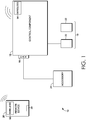
- FIG. 1 An embodiment of a system 10 for integrating automated furniture accessories with automated furniture items is seen in FIG. 1 .
- the system 10 generally includes a control component 12 having a wireless communication device 14, a controller area network (CAN) bus 16, integrated features 18 including a head motor 20 and a foot motor 22, and an automated furniture accessory 24 coupled to the CAN bus 16 of the control component 12.
- the control component 12 is depicted as being in wireless communication with a remote device 26 having a data port 28 and a wireless communication device 58.
- control component 12 controls various features of an automated furniture item that are operated based on commands received by the control component 12.
- the control component 12 may control integrated features 18 that are integral to the operation of the automated furniture item, such as a head motor 20 that raises and lowers the head of an adjustable bed.
- integrated features 18 are shown in FIG. 1 , such as the head motor 20 and the foot motor 22, it should be understood that any number or combination of integrated features 18 may be coupled to the control component 12, such as a massage motor, a programming port, a wired remote device, and the like.
- the control component 12 includes a processor and a memory capable of receiving and processing commands that are identifiable using the firmware of the control component 12.
- the control component 12 may receive a command to operate one or more of the integrated features 18 coupled to the automated furniture item.
- a remote device 26 may receive an input command from a user, which the remote device 26 transmits, wirelessly, to the wireless communication device 14 of control component 12, using wireless communication device 58.
- the command may relate to one or more of the integrated features 18 coupled to the control component 12, such as a command to lower both the head and the foot of an automated bed (using head motor 20 and foot motor 22).
- Wireless communication device 14 may be used in the transmission of wireless commands to and from the control component 12.
- wireless communication device 14 may be any wireless communication device used to transmit wireless communication to and from one or more remote devices that communicate wirelessly with the control component 12.
- the wireless communication device 14 may be a wireless device that executes a two-way communication protocol, such as a MiWi and/or Zigbee protocol.
- wireless communication device 14 communicates using 2.4GHz protocols, including 2.4GHz side bands or 2.4GHz stacks.
- wireless communication device 14 may execute a RF4CE protocol.
- wireless communication device 14 is used to communicate wirelessly between the control component 12 and the remote device 26, which may also be referred to as a remote control.
- control component 12 may also interact with external devices that are coupled to the control component 12, such as the automated furniture accessory 24 coupled to the CAN bus 16 of the control component 12.
- CAN bus 16 may directly or indirectly couple one or more automated furniture accessories 24 to control component 12.
- integrated features 18 may be directly coupled to the control component 12 (e.g., distributed with the control component 12 upon manufacture of the automated furniture device), while automated furniture accessories 24 may be coupled to the control component 12 at any time (e.g., after purchase of the automated furniture item having the control component 12).
- automated furniture accessories 24 may be coupled to the control component 12 of an automated furniture item that was not sold with such accessories.
- remote device 26 may be used to control one or more automated furniture accessories 24 coupled to a control component 12 of an automated furniture item.
- an automated furniture accessory 24 such as an electric heating blanket
- CAN bus 16 Upon connection with the CAN bus 16, items of information regarding the particular automated furniture accessory 24 plugged into the CAN bus 16 may be transmitted to the control component 12.
- items of information may include the identity of the automated furniture accessory 24, its manufacturer, a particular type of device (such as a type of heating blanket), general identifying information, placeholders, and other types of information that are identifiable by the control component 12.
- items of identifying information may be retrieved from the automated furniture accessory 24 by the control component 12, by virtue of the connection via CAN bus 16.
- control component 12 may then transmit one or more packets of information to the remote device 26, such as a remote control, according to a communication protocol.
- the remote device 26 receives the items of information over a wireless connection between the control component 12 and the remote device 26, utilizing the wireless communication device 14.
- the packets of information communicated between control component 12 and remote device 26 identify the particular automated furniture accessory 24 according to a protocol for communication between the control component 12 and the remote device 26.
- control component 12 acts as a 2-way wireless/CAN bridge such that an automated furniture accessory 24 (e.g., an inexpensive CAN accessory) can receive direct commands from the remote device 26.
- a communication protocol may specify particular packets of information that are required to be received by the remote device 26 before the remote device 26 can remotely direct the operation of the automated furniture accessory 24.
- packets of information 30 may be transmitted between control component 12 and remote device 26 using wireless communication device 14.
- Such exemplary packets may include a header packet 32, a message ID packet 34, message content packet 36, and a device ID packet 38.
- the type and number of packets transmitted as part of the communication protocol may vary, and any number of packets may be communicated between the control component 12 and the automated furniture accessory 24.
- header packet 32 provides information that identifies items such as a type of sender of a packet, a type of intended receiver of the packet, a message type, and the like. For example, header packet 32 may identify a control component 12 as the sender of a packet of data according to a communication protocol.
- message ID packet 34 provides information regarding a CAN bus and/or MiWi wireless communication device 14 involved in a transmission according to a communication protocol. For example, a message ID packet 34 may identify CAN bus 16 as being involved with the transmission according to a communication protocol. As such, the header packet 32 and/or the message ID packet 34 provide identifying information regarding the sender and receiver of a message, and the type of message that will be transmitted using one or more devices.
- a message content packet 36 provides the content of a message transmitted according to a communication protocol.
- a message content packet 36 may include instructions to manipulate one or more automated furniture accessories 24 coupled to the CAN bus 16 of a control component 12.
- message content packet 36 may include status data 40 and/or command data 42.
- status data 40 provides a status of one or more devices coupled to the control component 12.
- status data 40 may indicate, as part of a message content packet 36, whether an automated furniture accessory 24 (such as a heating blanket) is turned to a highest power.
- command data 42 may indicate, as part of a message content packet 36, a particular command directed at one or more devices coupled to the control component 12.
- command data 42 may indicate, as part of a message content packet 36, a direction to manipulate one or more features of an automated furniture accessory 24 coupled to the control component 12, such as directing the lowering of temperature on a heating blanket.
- exemplary packets of information 30 may include a device ID packet 38 that specifically identifies one or more items of hardware coupled to the control component 12.
- device ID packet 38 may indicate a particular type of automated furniture accessory 24 for control by the remote device 26. Accordingly, any number of device ID packets 38 may be transmitted between control component 12 and remote device 26.
- a communication protocol for controlling one or more automated furniture accessories 24 coupled to the control component 12 may include the transmission of one or more packets of information 30 between the control component 12 and the remote device 26.
- a control component 12 may determine one or more packets of information 30 to transmit to remote device 26. The determined one or more packets of information 30 may then enable the remote device 26 to control one or more automated furniture accessories 24 coupled to the control component 12, by virtue of the wireless connection between the remote device 26 and the control component 12.
- an automated furniture accessory 24 may be associated with one or more items of updateable information that may be changed after a user has initially coupled the particular automated furniture accessory 24 to the control component 12.
- the firmware of remote device 26 may be updated using data port 28.
- Data port 28 may be any feature associated with the remote device 26 that is capable of receiving data, such as a USB port.
- an updated feature of the automated furniture accessory 24 may be communicated to the control component 12 based on inputting the new and/or updated information into data port 28, such as plugging in a USB device containing such updated information.
- a new and/or updated automated furniture accessory 24 may be coupled to the control component 12.
- the control component 12 may be unable to recognize the newly-added automated furniture accessory 24.
- the control component 12 may have been manufactured without the ability to recognize and/or process particular commands associated with the new and/or updated automated furniture accessory 24.
- the control component 12 may be unable to determine one or more items of information to communicate according to the communication protocol, in order to delegate control of the automated furniture accessory 24 to the remote device 26.
- one or more updates may be provided to the remote device 26 via data port 28, and communicated from the remote device 26 to the control component 12 using wireless communication device 14. Accordingly, the remote device 26 may receive updates via data port 28, communicate such updates to the control component 12, and enable the control component 12 to exchange communication with the remote device 26 regarding the control of the automated furniture accessory 24.
- an exemplary flow diagram 44 of a method for integrating automated furniture accessories with automated furniture items is provided.
- an indication of an automated furniture accessory coupled to a control component is received. For example, such an indication may be received based on plugging an automated furniture accessory 24 into a CAN bus 16.
- one or more packets of information associated with the automated furniture accessory are identified.
- a control component 12 may identify one or more items and/or packets of information 30 according to a communication protocol for control of the automated furniture accessory 24 by a remote device 26.
- At block 50 at least one of the one or more packets of information is communicated to a remote device that is then adapted to control one or more features of the automated furniture accessory based on the communication between the remote device and the control component.
- the remote device 26 may control one or more features of the automated furniture accessory 24.
- a flow diagram 52 of a method for integrating automated furniture accessories with automated furniture items is provided.
- one or more items of identifying information associated with at least one automated furniture accessory coupled to a control component are received.
- a control component 12 may receive items of identifying information (e.g., a device type or a manufacturer) associated with a particular automated furniture accessory 24.
- at block 56 at least one of the one or more items of identifying information is communicated to a remote device, with the remote device being in wireless, two-way communication with the control component, and one or more features of the at least one automated furniture accessory being controlled by the remote device based on communication of the at least one of the one or more items of identifying information.
- features of an automated furniture accessory 24 may be controlled by the remote device 26 based on communication between the remote device 26 and the control component 12.
- the remote device 26 may control one or more features of the automated furniture accessory 24.
Landscapes
- Engineering & Computer Science (AREA)
- Computer Networks & Wireless Communication (AREA)
- Physics & Mathematics (AREA)
- General Physics & Mathematics (AREA)
- Selective Calling Equipment (AREA)
Description
- Embodiments of the present invention generally relate to a wireless, two-way communication protocol for integrating furniture accessories with automated furniture items. More particularly, embodiments of the present invention relate to a communication protocol for using a remote device to control an automated furniture accessory coupled to a control component of an automated furniture item.
- A variety of methods exist for using a controller to manipulate an automated furniture item. Such controllers direct the operation of various "standard" integrated elements for automated furniture items, such as a head motor or foot motor on an adjustable bed. However, external accessories may also be provided for use with an automated furniture item, such as a heating blanket. Unless the heating blanket is integrated into the control system of the automated furniture item, it will likely be controlled separately from the furniture item, requiring an additional device and/or remote. Further, the controller of an automated furniture item is typically equipped with the necessary firmware to operate the standard devices provided with the furniture item (i.e., those devices that the manufacturer intended to be operated by the furniture item controller).
- Accordingly, a need exists for a communication protocol that enables additional, automated furniture accessories to be operated by an automated furniture controller without the need to update the firmware of the furniture item controller.
- In
WO 2012/061406 A2 , a system and a method for integrating automated furniture accessories with automated furniture items are disclosed according to the respective preambles of independent claims 1 and 7. - The present invention generally relates to a system and method for integrating automated furniture accessories with automated furniture items. Embodiments of the invention include a communication protocol for using a remote device to control an automated furniture accessory coupled to a control component of an automated furniture item.
- According to the invention, a system as defined in independent claim 1 and a method as defined in independent claim 7 are provided. Additional objects, advantages, and novel features of the invention will be set forth in part in the description that follows, and in part will become apparent to those skilled in the art upon examination of the following, or may be learned by practice of the invention.
- The present invention is described in detail below with reference to the attached drawing figures, wherein:
-
FIG. 1 is a system for integrating automated furniture accessories with automated furniture items, in accordance with an embodiment of the invention; -
FIG. 2 is the system ofFIG. 1 for integrating automated furniture accessories with automated furniture items, including a plurality of packets of a communication protocol, in accordance with an embodiment of the invention; -
FIG. 3 is flow diagram of a method for integrating automated furniture accessories with automated furniture items, in accordance with an embodiment of the invention; and -
FIG. 4 is a flow diagram of a method for integrating automated furniture accessories with automated furniture items, in accordance with an embodiment of the invention. - An embodiment of a
system 10 for integrating automated furniture accessories with automated furniture items is seen inFIG. 1 . In the embodiment ofFIG. 1 , thesystem 10 generally includes acontrol component 12 having awireless communication device 14, a controller area network (CAN)bus 16, integratedfeatures 18 including ahead motor 20 and afoot motor 22, and anautomated furniture accessory 24 coupled to theCAN bus 16 of thecontrol component 12. Further, thecontrol component 12 is depicted as being in wireless communication with aremote device 26 having adata port 28 and awireless communication device 58. - In one embodiment,
control component 12 controls various features of an automated furniture item that are operated based on commands received by thecontrol component 12. For example, thecontrol component 12 may control integratedfeatures 18 that are integral to the operation of the automated furniture item, such as ahead motor 20 that raises and lowers the head of an adjustable bed. Although exemplary integratedfeatures 18 are shown inFIG. 1 , such as thehead motor 20 and thefoot motor 22, it should be understood that any number or combination of integratedfeatures 18 may be coupled to thecontrol component 12, such as a massage motor, a programming port, a wired remote device, and the like. - In some embodiments, the
control component 12 includes a processor and a memory capable of receiving and processing commands that are identifiable using the firmware of thecontrol component 12. For example, thecontrol component 12 may receive a command to operate one or more of the integratedfeatures 18 coupled to the automated furniture item. Accordingly, aremote device 26 may receive an input command from a user, which theremote device 26 transmits, wirelessly, to thewireless communication device 14 ofcontrol component 12, usingwireless communication device 58. The command may relate to one or more of the integratedfeatures 18 coupled to thecontrol component 12, such as a command to lower both the head and the foot of an automated bed (usinghead motor 20 and foot motor 22). -
Wireless communication device 14 may be used in the transmission of wireless commands to and from thecontrol component 12. As such,wireless communication device 14 may be any wireless communication device used to transmit wireless communication to and from one or more remote devices that communicate wirelessly with thecontrol component 12. For example, thewireless communication device 14 may be a wireless device that executes a two-way communication protocol, such as a MiWi and/or Zigbee protocol. In further embodiments,wireless communication device 14 communicates using 2.4GHz protocols, including 2.4GHz side bands or 2.4GHz stacks. Additionally, in one example,wireless communication device 14 may execute a RF4CE protocol. In some embodiments,wireless communication device 14 is used to communicate wirelessly between thecontrol component 12 and theremote device 26, which may also be referred to as a remote control. - In addition to communicating via
wireless communication device 14, thecontrol component 12 may also interact with external devices that are coupled to thecontrol component 12, such as theautomated furniture accessory 24 coupled to theCAN bus 16 of thecontrol component 12. In embodiments, CANbus 16 may directly or indirectly couple one or moreautomated furniture accessories 24 to controlcomponent 12. In one example, integratedfeatures 18 may be directly coupled to the control component 12 (e.g., distributed with thecontrol component 12 upon manufacture of the automated furniture device), whileautomated furniture accessories 24 may be coupled to thecontrol component 12 at any time (e.g., after purchase of the automated furniture item having the control component 12). In other words, in some embodiments,automated furniture accessories 24 may be coupled to thecontrol component 12 of an automated furniture item that was not sold with such accessories. - In embodiments of the present invention,
remote device 26 may be used to control one or moreautomated furniture accessories 24 coupled to acontrol component 12 of an automated furniture item. For example, anautomated furniture accessory 24, such as an electric heating blanket, may be plugged in to theCAN bus 16 of thecontrol component 12. Upon connection with the CANbus 16, items of information regarding the particularautomated furniture accessory 24 plugged into theCAN bus 16 may be transmitted to thecontrol component 12. Such items of information may include the identity of theautomated furniture accessory 24, its manufacturer, a particular type of device (such as a type of heating blanket), general identifying information, placeholders, and other types of information that are identifiable by thecontrol component 12. In some embodiments, items of identifying information may be retrieved from theautomated furniture accessory 24 by thecontrol component 12, by virtue of the connection via CANbus 16. - Having received identifying information regarding the particular
automated furniture accessory 24 plugged in to theCAN bus 16,control component 12 may then transmit one or more packets of information to theremote device 26, such as a remote control, according to a communication protocol. Theremote device 26 receives the items of information over a wireless connection between thecontrol component 12 and theremote device 26, utilizing thewireless communication device 14. In embodiments, the packets of information communicated betweencontrol component 12 andremote device 26 identify the particularautomated furniture accessory 24 according to a protocol for communication between thecontrol component 12 and theremote device 26. In further embodiments,control component 12 acts as a 2-way wireless/CAN bridge such that an automated furniture accessory 24 (e.g., an inexpensive CAN accessory) can receive direct commands from theremote device 26. - In another example, a communication protocol may specify particular packets of information that are required to be received by the
remote device 26 before theremote device 26 can remotely direct the operation of theautomated furniture accessory 24. Referring now toFIG. 2 , packets ofinformation 30 may be transmitted betweencontrol component 12 andremote device 26 usingwireless communication device 14. Such exemplary packets may include aheader packet 32, amessage ID packet 34,message content packet 36, and adevice ID packet 38. As will be understood, the type and number of packets transmitted as part of the communication protocol may vary, and any number of packets may be communicated between thecontrol component 12 and theautomated furniture accessory 24. - In one embodiment,
header packet 32 provides information that identifies items such as a type of sender of a packet, a type of intended receiver of the packet, a message type, and the like. For example,header packet 32 may identify acontrol component 12 as the sender of a packet of data according to a communication protocol. In another embodiment,message ID packet 34 provides information regarding a CAN bus and/or MiWiwireless communication device 14 involved in a transmission according to a communication protocol. For example, amessage ID packet 34 may identify CANbus 16 as being involved with the transmission according to a communication protocol. As such, theheader packet 32 and/or themessage ID packet 34 provide identifying information regarding the sender and receiver of a message, and the type of message that will be transmitted using one or more devices. - In further embodiments, a
message content packet 36 provides the content of a message transmitted according to a communication protocol. For example, amessage content packet 36 may include instructions to manipulate one or moreautomated furniture accessories 24 coupled to theCAN bus 16 of acontrol component 12. As such, in some embodiments,message content packet 36 may includestatus data 40 and/orcommand data 42. In embodiments,status data 40 provides a status of one or more devices coupled to thecontrol component 12. For example,status data 40 may indicate, as part of amessage content packet 36, whether an automated furniture accessory 24 (such as a heating blanket) is turned to a highest power. Similarly,command data 42 may indicate, as part of amessage content packet 36, a particular command directed at one or more devices coupled to thecontrol component 12. For example,command data 42 may indicate, as part of amessage content packet 36, a direction to manipulate one or more features of anautomated furniture accessory 24 coupled to thecontrol component 12, such as directing the lowering of temperature on a heating blanket. - In yet another embodiment, exemplary packets of
information 30 may include adevice ID packet 38 that specifically identifies one or more items of hardware coupled to thecontrol component 12. For example,device ID packet 38 may indicate a particular type ofautomated furniture accessory 24 for control by theremote device 26. Accordingly, any number ofdevice ID packets 38 may be transmitted betweencontrol component 12 andremote device 26. - In some embodiments, a communication protocol for controlling one or more
automated furniture accessories 24 coupled to thecontrol component 12 may include the transmission of one or more packets ofinformation 30 between thecontrol component 12 and theremote device 26. As such, in some embodiments, acontrol component 12 may determine one or more packets ofinformation 30 to transmit toremote device 26. The determined one or more packets ofinformation 30 may then enable theremote device 26 to control one or moreautomated furniture accessories 24 coupled to thecontrol component 12, by virtue of the wireless connection between theremote device 26 and thecontrol component 12. - In some embodiments, an
automated furniture accessory 24 may be associated with one or more items of updateable information that may be changed after a user has initially coupled the particularautomated furniture accessory 24 to thecontrol component 12. In other words, after aremote device 26 has been configured to control a particularautomated furniture accessory 24, one or more updates may become available for theautomated furniture accessory 24. Accordingly, in some embodiments, the firmware ofremote device 26 may be updated usingdata port 28.Data port 28 may be any feature associated with theremote device 26 that is capable of receiving data, such as a USB port. In one example, an updated feature of theautomated furniture accessory 24 may be communicated to thecontrol component 12 based on inputting the new and/or updated information intodata port 28, such as plugging in a USB device containing such updated information. - In a further embodiment, a new and/or updated
automated furniture accessory 24 may be coupled to thecontrol component 12. In one embodiment, thecontrol component 12 may be unable to recognize the newly-addedautomated furniture accessory 24. For example, thecontrol component 12 may have been manufactured without the ability to recognize and/or process particular commands associated with the new and/or updatedautomated furniture accessory 24. In another example, thecontrol component 12 may be unable to determine one or more items of information to communicate according to the communication protocol, in order to delegate control of theautomated furniture accessory 24 to theremote device 26. As such, one or more updates may be provided to theremote device 26 viadata port 28, and communicated from theremote device 26 to thecontrol component 12 usingwireless communication device 14. Accordingly, theremote device 26 may receive updates viadata port 28, communicate such updates to thecontrol component 12, and enable thecontrol component 12 to exchange communication with theremote device 26 regarding the control of theautomated furniture accessory 24. - Referring next to
FIG. 3 , an exemplary flow diagram 44 of a method for integrating automated furniture accessories with automated furniture items is provided. Atblock 46, an indication of an automated furniture accessory coupled to a control component is received. For example, such an indication may be received based on plugging anautomated furniture accessory 24 into aCAN bus 16. Atblock 48, one or more packets of information associated with the automated furniture accessory are identified. As discussed above, in some embodiments, acontrol component 12 may identify one or more items and/or packets ofinformation 30 according to a communication protocol for control of theautomated furniture accessory 24 by aremote device 26. As such, atblock 50, at least one of the one or more packets of information is communicated to a remote device that is then adapted to control one or more features of the automated furniture accessory based on the communication between the remote device and the control component. For example, having received one or more packets ofinformation 30 from thecontrol component 12, theremote device 26 may control one or more features of theautomated furniture accessory 24. - Turning now to
FIG. 4 , a flow diagram 52 of a method for integrating automated furniture accessories with automated furniture items is provided. Atblock 54, one or more items of identifying information associated with at least one automated furniture accessory coupled to a control component are received. For example, acontrol component 12 may receive items of identifying information (e.g., a device type or a manufacturer) associated with a particularautomated furniture accessory 24. Atblock 56, at least one of the one or more items of identifying information is communicated to a remote device, with the remote device being in wireless, two-way communication with the control component, and one or more features of the at least one automated furniture accessory being controlled by the remote device based on communication of the at least one of the one or more items of identifying information. Accordingly, in one embodiment, features of anautomated furniture accessory 24 may be controlled by theremote device 26 based on communication between theremote device 26 and thecontrol component 12. In other words, by virtue of the direct connection of theautomated furniture accessory 24 to theCAN bus 16 of thecontrol component 12, as well as the wireless connection between theremote device 26 and thewireless communication device 14 ofcontrol component 12, theremote device 26 may control one or more features of theautomated furniture accessory 24. - From the foregoing, it will be seen that this invention is one well adapted to attain all the ends and objects hereinabove set forth together with other advantages, which are obvious and inherent to the structure.
- It will be understood that certain features and subcombinations are of utility and may be employed without reference to other features and subcombinations. This is contemplated by and is within the scope of the claims.
- Since many possible embodiments may be made of the invention without departing from the scope thereof, it is to be understood that all matter herein set forth or shown in the accompanying drawings is to be interpreted as illustrative and not in a limiting sense.
Claims (11)
- A system (10) for integrating automated furniture accessories (24) with automated furniture items, comprising:a control component (12) for controlling features of an automated furniture item, the control component comprising: (1) a wireless communication device (14); (2) a bus; and (3) at least one automated furniture accessory (24) coupled to the bus, wherein one or more features of the at least one automated furniture accessory (24) are controllable by a remote device (26) wirelessly coupled to the control component (12),characterized in thatthe control component (12) is configured to automatically receive one or more items of information (30), provided by the at least one automated furniture accessory (24), in response to coupling the at least one automated furniture accessory (24) to the control component (12); andthe remote device (26) is configured to wirelessly control the at least one automated furniture accessory (24) based on communication between the control component (12) and the remote device (26), wherein the communication between the control component (12) and the remote device (26) comprises the one or more items of information (30) provided to the control component (12) by the automated furniture accessory (24).
- The system (10) of claim 1, wherein the bus is a CAN bus (16), and wherein the one or more items of information (30) are provided to the control component (12) based on coupling the automated furniture accessory (24) to the CAN bus (16) of the control component (12).
- The system (10) of any one of claims 1-2, wherein the wireless communication device (14) is a two-way communication device that facilitates two-way communication between the control component (12) and the remote device (26).
- The system (10) of any one of claims 1-3, wherein the remote device (26) is adapted to receive information (30) from and transmit information (30) to the control component (12) using the wireless communication device (14).
- The system (10) of claim 4, wherein the remote device (26) comprises updateable firmware adapted to receive information (30) regarding an automated furniture accessory (24) coupled to the control component (12).
- The system (10) of claim 4 or 5, wherein the remote device (26) comprises a screen comprising one or more control indicators, wherein the one or more control indicators are updated based on receiving information (30) regarding an automated furniture accessory (24) coupled to the control component (12).
- A method for integrating automated furniture accessories (24) with automated furniture items, the method being characterized by comprising:automatically receiving by a control component (12) for controlling features of an automated furniture item, an indication of an automated furniture accessory (24) in response to coupling the automated furniture accessory (24) to the control component (12);identifying one or more packets of information (30) associated with the automated furniture accessory (24); andcommunicating at least one of the one or more packets of information (30) from the control component (12) to a remote device (26), wherein the remote device (26) is adapted to control one or more features of the automated furniture accessory (24) based at least in part on the at least one of the one or more packets of information (30) communicated between the control component (12) and the remote device (26).
- The method of claim 7, wherein receiving an indication of an automated furniture accessory (24) comprises receiving an indication that an automated furniture accessory (24) external to the control component (12) is coupled to the control component (12).
- The method of claim 8, wherein receiving an indication of an automated furniture accessory (24) comprises receiving an indication of one or more of an accessory type, an accessory manufacturer, and an accessory model.
- The method of any one of claims 7 to 9, wherein identifying one or more packets of information (30) comprises identifying one or more packets (32, 34, 36, 38) indicating at least one protocol for communication between the remote device (26) and the control component (12).
- The method of claim 10, wherein controlling the automated furniture accessory (24) based at least in part on the at least one of the one or more packets of information (30) communicated between the control component (12) and the remote device (26) comprises executing the at least one protocol such that the automated furniture accessory (24) is controlled by the remote device (26) wirelessly communicating with the control component (12).
Applications Claiming Priority (2)
| Application Number | Priority Date | Filing Date | Title |
|---|---|---|---|
| US13/749,087 US9412262B2 (en) | 2013-01-24 | 2013-01-24 | Wireless two-way communication protocol for automated furniture accessory integration |
| PCT/US2013/077557 WO2014116387A1 (en) | 2013-01-24 | 2013-12-23 | Wireless two-way communication protocol for automated furniture accessory integration |
Publications (3)
| Publication Number | Publication Date |
|---|---|
| EP2948861A1 EP2948861A1 (en) | 2015-12-02 |
| EP2948861A4 EP2948861A4 (en) | 2016-09-21 |
| EP2948861B1 true EP2948861B1 (en) | 2018-10-03 |
Family
ID=51207278
Family Applications (1)
| Application Number | Title | Priority Date | Filing Date |
|---|---|---|---|
| EP13872762.3A Not-in-force EP2948861B1 (en) | 2013-01-24 | 2013-12-23 | Wireless two-way communication protocol for automated furniture accessory integration |
Country Status (3)
| Country | Link |
|---|---|
| US (1) | US9412262B2 (en) |
| EP (1) | EP2948861B1 (en) |
| WO (1) | WO2014116387A1 (en) |
Families Citing this family (13)
| Publication number | Priority date | Publication date | Assignee | Title |
|---|---|---|---|---|
| EP3821766A1 (en) | 2014-12-29 | 2021-05-19 | Herman Miller, Inc. | System architecture for office productivity structure communications |
| ES2747500T3 (en) * | 2015-11-16 | 2020-03-10 | Dewertokin Gmbh | Cabinet drive with electric motor and procedure to control a cabinet drive with electric motor |
| US11605037B2 (en) | 2016-07-20 | 2023-03-14 | Fisher-Rosemount Systems, Inc. | Fleet management system for portable maintenance tools |
| US10585422B2 (en) * | 2016-07-22 | 2020-03-10 | Fisher-Rosemount Systems, Inc. | Portable field maintenance tool system having interchangeable functional modules |
| CN110074596B (en) * | 2019-03-29 | 2021-06-11 | 杨松 | Electric bed resetting method and device, computer equipment and storage medium |
| US10932379B2 (en) | 2019-04-01 | 2021-02-23 | La-Z-Boy Incorporated | Furniture member having circuit board assembly |
| USD897970S1 (en) | 2019-04-01 | 2020-10-06 | La-Z-Boy Incorporated | Mounting cradle with remote control device for motion furniture |
| USD909315S1 (en) | 2019-04-01 | 2021-02-02 | La-Z-Boy Incorporated | Remote control device for motion furniture |
| USD897968S1 (en) | 2019-04-01 | 2020-10-06 | La-Z-Boy Incorporated | Control panel for motion furniture |
| US10925404B2 (en) | 2019-04-01 | 2021-02-23 | La-Z-Boy Incorporated | Modular components for furniture members |
| USD897969S1 (en) | 2019-04-01 | 2020-10-06 | La-Z-Boy Incorporated | Mounting cradle for remote control device for motion furniture |
| US11445817B2 (en) | 2019-09-13 | 2022-09-20 | Ergotron, Inc. | Workstation height-adjustment monitoring |
| CN113645596A (en) * | 2021-07-14 | 2021-11-12 | 麒盛科技股份有限公司 | Networking pairing method and device for electric bed based on Internet of things |
Family Cites Families (49)
| Publication number | Priority date | Publication date | Assignee | Title |
|---|---|---|---|---|
| US5086385A (en) | 1989-01-31 | 1992-02-04 | Custom Command Systems | Expandable home automation system |
| US5109222A (en) | 1989-03-27 | 1992-04-28 | John Welty | Remote control system for control of electrically operable equipment in people occupiable structures |
| US6542076B1 (en) * | 1993-06-08 | 2003-04-01 | Raymond Anthony Joao | Control, monitoring and/or security apparatus and method |
| US5782036A (en) * | 1994-04-28 | 1998-07-21 | Fiorenza Bertieri | Disabled persons multiple appliance/window remote control system |
| US5971597A (en) | 1995-03-29 | 1999-10-26 | Hubbell Corporation | Multifunction sensor and network sensor system |
| US5602664A (en) | 1995-06-06 | 1997-02-11 | Thomson Consumer Electronics, Inc. | Infrared repeater |
| US5636211A (en) | 1995-08-15 | 1997-06-03 | Motorola, Inc. | Universal multimedia access device |
| DE69736278T2 (en) * | 1996-02-22 | 2007-06-06 | Kvaser Consultant Ab | Device for influencing messages in a CAN system |
| US6469633B1 (en) | 1997-01-06 | 2002-10-22 | Openglobe Inc. | Remote control of electronic devices |
| US6256739B1 (en) | 1997-10-30 | 2001-07-03 | Juno Online Services, Inc. | Method and apparatus to determine user identity and limit access to a communications network |
| US5963624A (en) | 1997-12-05 | 1999-10-05 | Zilog, Inc. | Digital cordless telephone with remote control feature |
| US6169879B1 (en) * | 1998-09-16 | 2001-01-02 | Webtv Networks, Inc. | System and method of interconnecting and using components of home entertainment system |
| GB2345368B (en) * | 1998-12-31 | 2003-05-14 | Nokia Mobile Phones Ltd | A portable controller |
| ATE345760T1 (en) * | 1999-12-29 | 2006-12-15 | Hill Rom Services Inc | SICK BED |
| US6748278B1 (en) | 2000-03-13 | 2004-06-08 | Microsoft Corporation | Remote controlled system with computer-based remote control facilitator |
| CA2409851C (en) * | 2000-05-23 | 2013-03-26 | M2M Solutions Llc | Programmable communicator |
| US7136913B2 (en) | 2000-05-31 | 2006-11-14 | Lab 7 Networks, Inc. | Object oriented communication among platform independent systems across a firewall over the internet using HTTP-SOAP |
| US6870477B2 (en) | 2001-07-31 | 2005-03-22 | International Business Machines Corporation | Method and apparatus for wireless mobile seating platform |
| US7009522B2 (en) | 2001-09-28 | 2006-03-07 | Seatsignal, Inc. | Object-proximity monitoring and alarm system |
| US7151968B2 (en) * | 2001-11-01 | 2006-12-19 | Salton, Inc. | Intelligent coffeemaker appliance |
| US7095456B2 (en) * | 2001-11-21 | 2006-08-22 | Ui Evolution, Inc. | Field extensible controllee sourced universal remote control method and apparatus |
| US6998955B2 (en) | 2002-08-09 | 2006-02-14 | Ballew Michael A | Virtual electronic remote control device |
| AU2003263610A1 (en) | 2002-09-30 | 2004-04-23 | Matsushita Electric Industrial Co., Ltd. | Apparatuses, method and computer software products for controlling a home terminal |
| US7006006B2 (en) | 2002-12-05 | 2006-02-28 | Witkow Edward H | System and method for controlling home entertainment units with radio frequency and infrared signals |
| US7044619B2 (en) | 2003-03-11 | 2006-05-16 | Sanderlin Jerry D | Remote control tower device and system |
| US20040203387A1 (en) | 2003-03-31 | 2004-10-14 | Sbc Knowledge Ventures, L.P. | System and method for controlling appliances with a wireless data enabled remote control |
| US7068181B2 (en) * | 2003-07-30 | 2006-06-27 | Lear Corporation | Programmable appliance remote control |
| US7155305B2 (en) | 2003-11-04 | 2006-12-26 | Universal Electronics Inc. | System and methods for home appliance identification and control in a networked environment |
| US6964370B1 (en) | 2004-08-05 | 2005-11-15 | International Business Machines Corporation | RFID smart office chair |
| US7768420B2 (en) | 2004-10-29 | 2010-08-03 | Intel Corporation | Operation and control of wireless appliance networks |
| US7349772B2 (en) * | 2004-12-16 | 2008-03-25 | International Truck Intellectual Property Company, Llc | Vehicle integrated radio remote control |
| TWI328936B (en) * | 2006-09-01 | 2010-08-11 | Live Experiment Design Corp | Remote controlling system for controlling electronic equipments within situation |
| US20120138067A1 (en) * | 2007-09-14 | 2012-06-07 | Rawls-Meehan Martin B | System and method for mitigating snoring in an adjustable bed |
| WO2009055432A2 (en) | 2007-10-22 | 2009-04-30 | Rawls-Meehan Martin B | Adjustable bed position control |
| US8926535B2 (en) | 2006-09-14 | 2015-01-06 | Martin B. Rawls-Meehan | Adjustable bed position control |
| US20080077020A1 (en) | 2006-09-22 | 2008-03-27 | Bam Labs, Inc. | Method and apparatus for monitoring vital signs remotely |
| US20080262657A1 (en) | 2007-04-17 | 2008-10-23 | L&P Property Management Company | System and method for controlling adjustable furniture |
| US20100162285A1 (en) | 2007-09-11 | 2010-06-24 | Yossef Gerard Cohen | Presence Detector and Method for Estimating an Audience |
| US8082160B2 (en) | 2007-10-26 | 2011-12-20 | Hill-Rom Services, Inc. | System and method for collection and communication of data from multiple patient care devices |
| US8634720B2 (en) | 2008-02-28 | 2014-01-21 | Robert Bosch Gmbh | Remote control relay for wirelessly-controlled devices |
| US8009042B2 (en) | 2008-09-03 | 2011-08-30 | Lutron Electronics Co., Inc. | Radio-frequency lighting control system with occupancy sensing |
| CN101808025B (en) | 2010-04-13 | 2014-08-20 | 中兴通讯股份有限公司 | Device, system and method for realizing intelligent home application |
| US20120072236A1 (en) | 2010-08-06 | 2012-03-22 | Benjamin Atkin | Insulin pen data recording and transmission device |
| US20130024018A1 (en) | 2011-07-22 | 2013-01-24 | Htc Corporation | Multimedia control method and multimedia control system |
| US8816845B2 (en) | 2011-08-30 | 2014-08-26 | Verizon Patent And Licensing Inc. | Method and system for generating an alert based on car seat use detection |
| US9089223B2 (en) | 2012-01-09 | 2015-07-28 | L&P Property Management Company | Occupancy detection for furniture |
| US9528812B2 (en) | 2012-01-09 | 2016-12-27 | L&P Property Management Company | Capacitive wire sensing for furniture |
| EP2625983A1 (en) | 2012-02-07 | 2013-08-14 | KIH-utveckling AB | Workplace with integrated interface for identification of a user |
| US20140302795A1 (en) | 2013-01-24 | 2014-10-09 | L&P Property Management Company | User identification method for automated furniture |
-
2013
- 2013-01-24 US US13/749,087 patent/US9412262B2/en not_active Expired - Fee Related
- 2013-12-23 WO PCT/US2013/077557 patent/WO2014116387A1/en not_active Ceased
- 2013-12-23 EP EP13872762.3A patent/EP2948861B1/en not_active Not-in-force
Also Published As
| Publication number | Publication date |
|---|---|
| EP2948861A1 (en) | 2015-12-02 |
| US20140203919A1 (en) | 2014-07-24 |
| EP2948861A4 (en) | 2016-09-21 |
| WO2014116387A1 (en) | 2014-07-31 |
| US9412262B2 (en) | 2016-08-09 |
Similar Documents
| Publication | Publication Date | Title |
|---|---|---|
| US9412262B2 (en) | Wireless two-way communication protocol for automated furniture accessory integration | |
| US9514637B2 (en) | Wireless two-way communication protocol for automated furniture accessory integration | |
| CN104676842B (en) | Control method, control device and the line control machine of line control machine | |
| US20140203920A1 (en) | Remote and controller synchronization for automated furniture controls | |
| KR102393277B1 (en) | Air-conditioner repeater, air-conditioner system and the control method thereof | |
| EP3669124B1 (en) | Appliances and control method thereof | |
| WO2016022018A4 (en) | Universal control system for wireless sensor networks | |
| KR101242054B1 (en) | M2M Module for Supporting Serial Communication Emulation through WiBro Network and Operation Method thereof | |
| JP6020478B2 (en) | Communication adapter | |
| JP6833044B2 (en) | Air conditioning system | |
| KR101673943B1 (en) | Integration smart device interface system using wire-wireless communication and method thereof | |
| CN105938328A (en) | Method for controlling smart home devices and controller | |
| US20170308047A1 (en) | Control processing method, electric device, and control processing program | |
| CN202870582U (en) | Building intelligent system and automatic device thereof | |
| CN114740739B (en) | Methods, devices, systems, and storage media for centralized control of smart home appliances. | |
| CN102111580B (en) | A kind of electronic installation and remote control thereof thereof with RF remote control module | |
| CA2935725C (en) | Wireless two-way communication protocol for automated furniture accessory integration | |
| JP5771548B2 (en) | Controller | |
| JP4950617B2 (en) | Air conditioning management apparatus, air conditioning management method, and air conditioning management program | |
| JP2016126639A5 (en) | CONTROL DEVICE, DEVICE, CONTROL METHOD, PROGRAM, AND CONTROL SYSTEM | |
| KR100873905B1 (en) | Communication system using Zigbee and its control method | |
| KR101738689B1 (en) | A network system | |
| KR102095906B1 (en) | Automatic setting method of heating valve controller and valve controller linked with home net | |
| KR20170000549U (en) | System for controlling a microclimate in a space with the aid of wireless connections of various types, microclimate control device and microclimate control method | |
| KR101658092B1 (en) | Building automation system, facilities control apparatus comprised therein and control method of the facilities control apparatus |
Legal Events
| Date | Code | Title | Description |
|---|---|---|---|
| PUAI | Public reference made under article 153(3) epc to a published international application that has entered the european phase |
Free format text: ORIGINAL CODE: 0009012 |
|
| 17P | Request for examination filed |
Effective date: 20150730 |
|
| AK | Designated contracting states |
Kind code of ref document: A1 Designated state(s): AL AT BE BG CH CY CZ DE DK EE ES FI FR GB GR HR HU IE IS IT LI LT LU LV MC MK MT NL NO PL PT RO RS SE SI SK SM TR |
|
| AX | Request for extension of the european patent |
Extension state: BA ME |
|
| DAX | Request for extension of the european patent (deleted) | ||
| A4 | Supplementary search report drawn up and despatched |
Effective date: 20160819 |
|
| RIC1 | Information provided on ipc code assigned before grant |
Ipc: A47C 31/00 20060101ALI20160812BHEP Ipc: G06F 15/16 20060101AFI20160812BHEP |
|
| 17Q | First examination report despatched |
Effective date: 20180111 |
|
| GRAP | Despatch of communication of intention to grant a patent |
Free format text: ORIGINAL CODE: EPIDOSNIGR1 |
|
| INTG | Intention to grant announced |
Effective date: 20180517 |
|
| GRAS | Grant fee paid |
Free format text: ORIGINAL CODE: EPIDOSNIGR3 |
|
| GRAA | (expected) grant |
Free format text: ORIGINAL CODE: 0009210 |
|
| AK | Designated contracting states |
Kind code of ref document: B1 Designated state(s): AL AT BE BG CH CY CZ DE DK EE ES FI FR GB GR HR HU IE IS IT LI LT LU LV MC MK MT NL NO PL PT RO RS SE SI SK SM TR |
|
| REG | Reference to a national code |
Ref country code: GB Ref legal event code: FG4D |
|
| REG | Reference to a national code |
Ref country code: CH Ref legal event code: EP Ref country code: AT Ref legal event code: REF Ref document number: 1049367 Country of ref document: AT Kind code of ref document: T Effective date: 20181015 |
|
| REG | Reference to a national code |
Ref country code: DE Ref legal event code: R096 Ref document number: 602013044660 Country of ref document: DE |
|
| REG | Reference to a national code |
Ref country code: IE Ref legal event code: FG4D |
|
| REG | Reference to a national code |
Ref country code: NL Ref legal event code: MP Effective date: 20181003 |
|
| REG | Reference to a national code |
Ref country code: LT Ref legal event code: MG4D |
|
| REG | Reference to a national code |
Ref country code: AT Ref legal event code: MK05 Ref document number: 1049367 Country of ref document: AT Kind code of ref document: T Effective date: 20181003 |
|
| PG25 | Lapsed in a contracting state [announced via postgrant information from national office to epo] |
Ref country code: NL Free format text: LAPSE BECAUSE OF FAILURE TO SUBMIT A TRANSLATION OF THE DESCRIPTION OR TO PAY THE FEE WITHIN THE PRESCRIBED TIME-LIMIT Effective date: 20181003 |
|
| PG25 | Lapsed in a contracting state [announced via postgrant information from national office to epo] |
Ref country code: BG Free format text: LAPSE BECAUSE OF FAILURE TO SUBMIT A TRANSLATION OF THE DESCRIPTION OR TO PAY THE FEE WITHIN THE PRESCRIBED TIME-LIMIT Effective date: 20190103 Ref country code: NO Free format text: LAPSE BECAUSE OF FAILURE TO SUBMIT A TRANSLATION OF THE DESCRIPTION OR TO PAY THE FEE WITHIN THE PRESCRIBED TIME-LIMIT Effective date: 20190103 Ref country code: PL Free format text: LAPSE BECAUSE OF FAILURE TO SUBMIT A TRANSLATION OF THE DESCRIPTION OR TO PAY THE FEE WITHIN THE PRESCRIBED TIME-LIMIT Effective date: 20181003 Ref country code: HR Free format text: LAPSE BECAUSE OF FAILURE TO SUBMIT A TRANSLATION OF THE DESCRIPTION OR TO PAY THE FEE WITHIN THE PRESCRIBED TIME-LIMIT Effective date: 20181003 Ref country code: AT Free format text: LAPSE BECAUSE OF FAILURE TO SUBMIT A TRANSLATION OF THE DESCRIPTION OR TO PAY THE FEE WITHIN THE PRESCRIBED TIME-LIMIT Effective date: 20181003 Ref country code: LV Free format text: LAPSE BECAUSE OF FAILURE TO SUBMIT A TRANSLATION OF THE DESCRIPTION OR TO PAY THE FEE WITHIN THE PRESCRIBED TIME-LIMIT Effective date: 20181003 Ref country code: FI Free format text: LAPSE BECAUSE OF FAILURE TO SUBMIT A TRANSLATION OF THE DESCRIPTION OR TO PAY THE FEE WITHIN THE PRESCRIBED TIME-LIMIT Effective date: 20181003 Ref country code: IS Free format text: LAPSE BECAUSE OF FAILURE TO SUBMIT A TRANSLATION OF THE DESCRIPTION OR TO PAY THE FEE WITHIN THE PRESCRIBED TIME-LIMIT Effective date: 20190203 Ref country code: CZ Free format text: LAPSE BECAUSE OF FAILURE TO SUBMIT A TRANSLATION OF THE DESCRIPTION OR TO PAY THE FEE WITHIN THE PRESCRIBED TIME-LIMIT Effective date: 20181003 Ref country code: ES Free format text: LAPSE BECAUSE OF FAILURE TO SUBMIT A TRANSLATION OF THE DESCRIPTION OR TO PAY THE FEE WITHIN THE PRESCRIBED TIME-LIMIT Effective date: 20181003 Ref country code: LT Free format text: LAPSE BECAUSE OF FAILURE TO SUBMIT A TRANSLATION OF THE DESCRIPTION OR TO PAY THE FEE WITHIN THE PRESCRIBED TIME-LIMIT Effective date: 20181003 |
|
| PG25 | Lapsed in a contracting state [announced via postgrant information from national office to epo] |
Ref country code: PT Free format text: LAPSE BECAUSE OF FAILURE TO SUBMIT A TRANSLATION OF THE DESCRIPTION OR TO PAY THE FEE WITHIN THE PRESCRIBED TIME-LIMIT Effective date: 20190203 Ref country code: SE Free format text: LAPSE BECAUSE OF FAILURE TO SUBMIT A TRANSLATION OF THE DESCRIPTION OR TO PAY THE FEE WITHIN THE PRESCRIBED TIME-LIMIT Effective date: 20181003 Ref country code: GR Free format text: LAPSE BECAUSE OF FAILURE TO SUBMIT A TRANSLATION OF THE DESCRIPTION OR TO PAY THE FEE WITHIN THE PRESCRIBED TIME-LIMIT Effective date: 20190104 Ref country code: AL Free format text: LAPSE BECAUSE OF FAILURE TO SUBMIT A TRANSLATION OF THE DESCRIPTION OR TO PAY THE FEE WITHIN THE PRESCRIBED TIME-LIMIT Effective date: 20181003 Ref country code: RS Free format text: LAPSE BECAUSE OF FAILURE TO SUBMIT A TRANSLATION OF THE DESCRIPTION OR TO PAY THE FEE WITHIN THE PRESCRIBED TIME-LIMIT Effective date: 20181003 |
|
| REG | Reference to a national code |
Ref country code: DE Ref legal event code: R119 Ref document number: 602013044660 Country of ref document: DE |
|
| PG25 | Lapsed in a contracting state [announced via postgrant information from national office to epo] |
Ref country code: DK Free format text: LAPSE BECAUSE OF FAILURE TO SUBMIT A TRANSLATION OF THE DESCRIPTION OR TO PAY THE FEE WITHIN THE PRESCRIBED TIME-LIMIT Effective date: 20181003 Ref country code: IT Free format text: LAPSE BECAUSE OF FAILURE TO SUBMIT A TRANSLATION OF THE DESCRIPTION OR TO PAY THE FEE WITHIN THE PRESCRIBED TIME-LIMIT Effective date: 20181003 |
|
| REG | Reference to a national code |
Ref country code: CH Ref legal event code: PL |
|
| PLBE | No opposition filed within time limit |
Free format text: ORIGINAL CODE: 0009261 |
|
| STAA | Information on the status of an ep patent application or granted ep patent |
Free format text: STATUS: NO OPPOSITION FILED WITHIN TIME LIMIT |
|
| PG25 | Lapsed in a contracting state [announced via postgrant information from national office to epo] |
Ref country code: MC Free format text: LAPSE BECAUSE OF FAILURE TO SUBMIT A TRANSLATION OF THE DESCRIPTION OR TO PAY THE FEE WITHIN THE PRESCRIBED TIME-LIMIT Effective date: 20181003 Ref country code: EE Free format text: LAPSE BECAUSE OF FAILURE TO SUBMIT A TRANSLATION OF THE DESCRIPTION OR TO PAY THE FEE WITHIN THE PRESCRIBED TIME-LIMIT Effective date: 20181003 Ref country code: SM Free format text: LAPSE BECAUSE OF FAILURE TO SUBMIT A TRANSLATION OF THE DESCRIPTION OR TO PAY THE FEE WITHIN THE PRESCRIBED TIME-LIMIT Effective date: 20181003 Ref country code: RO Free format text: LAPSE BECAUSE OF FAILURE TO SUBMIT A TRANSLATION OF THE DESCRIPTION OR TO PAY THE FEE WITHIN THE PRESCRIBED TIME-LIMIT Effective date: 20181003 Ref country code: SK Free format text: LAPSE BECAUSE OF FAILURE TO SUBMIT A TRANSLATION OF THE DESCRIPTION OR TO PAY THE FEE WITHIN THE PRESCRIBED TIME-LIMIT Effective date: 20181003 Ref country code: LU Free format text: LAPSE BECAUSE OF NON-PAYMENT OF DUE FEES Effective date: 20181223 |
|
| 26N | No opposition filed |
Effective date: 20190704 |
|
| REG | Reference to a national code |
Ref country code: IE Ref legal event code: MM4A |
|
| GBPC | Gb: european patent ceased through non-payment of renewal fee |
Effective date: 20190103 |
|
| REG | Reference to a national code |
Ref country code: BE Ref legal event code: MM Effective date: 20181231 |
|
| PG25 | Lapsed in a contracting state [announced via postgrant information from national office to epo] |
Ref country code: IE Free format text: LAPSE BECAUSE OF NON-PAYMENT OF DUE FEES Effective date: 20181223 Ref country code: SI Free format text: LAPSE BECAUSE OF FAILURE TO SUBMIT A TRANSLATION OF THE DESCRIPTION OR TO PAY THE FEE WITHIN THE PRESCRIBED TIME-LIMIT Effective date: 20181003 Ref country code: DE Free format text: LAPSE BECAUSE OF NON-PAYMENT OF DUE FEES Effective date: 20190702 Ref country code: FR Free format text: LAPSE BECAUSE OF NON-PAYMENT OF DUE FEES Effective date: 20181231 |
|
| PG25 | Lapsed in a contracting state [announced via postgrant information from national office to epo] |
Ref country code: BE Free format text: LAPSE BECAUSE OF NON-PAYMENT OF DUE FEES Effective date: 20181231 |
|
| PG25 | Lapsed in a contracting state [announced via postgrant information from national office to epo] |
Ref country code: GB Free format text: LAPSE BECAUSE OF NON-PAYMENT OF DUE FEES Effective date: 20190103 Ref country code: CH Free format text: LAPSE BECAUSE OF NON-PAYMENT OF DUE FEES Effective date: 20181231 Ref country code: LI Free format text: LAPSE BECAUSE OF NON-PAYMENT OF DUE FEES Effective date: 20181231 |
|
| PG25 | Lapsed in a contracting state [announced via postgrant information from national office to epo] |
Ref country code: MT Free format text: LAPSE BECAUSE OF NON-PAYMENT OF DUE FEES Effective date: 20181223 |
|
| PG25 | Lapsed in a contracting state [announced via postgrant information from national office to epo] |
Ref country code: TR Free format text: LAPSE BECAUSE OF FAILURE TO SUBMIT A TRANSLATION OF THE DESCRIPTION OR TO PAY THE FEE WITHIN THE PRESCRIBED TIME-LIMIT Effective date: 20181003 |
|
| PG25 | Lapsed in a contracting state [announced via postgrant information from national office to epo] |
Ref country code: HU Free format text: LAPSE BECAUSE OF FAILURE TO SUBMIT A TRANSLATION OF THE DESCRIPTION OR TO PAY THE FEE WITHIN THE PRESCRIBED TIME-LIMIT; INVALID AB INITIO Effective date: 20131223 Ref country code: CY Free format text: LAPSE BECAUSE OF FAILURE TO SUBMIT A TRANSLATION OF THE DESCRIPTION OR TO PAY THE FEE WITHIN THE PRESCRIBED TIME-LIMIT Effective date: 20181003 Ref country code: MK Free format text: LAPSE BECAUSE OF NON-PAYMENT OF DUE FEES Effective date: 20181003 |