EP2948686B1 - Bolt, and rock drill with bolt - Google Patents
Bolt, and rock drill with bolt Download PDFInfo
- Publication number
- EP2948686B1 EP2948686B1 EP14743283.5A EP14743283A EP2948686B1 EP 2948686 B1 EP2948686 B1 EP 2948686B1 EP 14743283 A EP14743283 A EP 14743283A EP 2948686 B1 EP2948686 B1 EP 2948686B1
- Authority
- EP
- European Patent Office
- Prior art keywords
- bolt
- housing part
- collar
- housing
- diameter
- Prior art date
- Legal status (The legal status is an assumption and is not a legal conclusion. Google has not performed a legal analysis and makes no representation as to the accuracy of the status listed.)
- Active
Links
- 239000011435 rock Substances 0.000 title claims description 27
- 230000007704 transition Effects 0.000 claims description 4
- 238000005553 drilling Methods 0.000 description 3
- 229910000831 Steel Inorganic materials 0.000 description 2
- 239000010959 steel Substances 0.000 description 2
- 238000013459 approach Methods 0.000 description 1
- 238000005336 cracking Methods 0.000 description 1
- 230000003247 decreasing effect Effects 0.000 description 1
- 238000012986 modification Methods 0.000 description 1
- 230000004048 modification Effects 0.000 description 1
- 238000010008 shearing Methods 0.000 description 1
Images

Classifications
-
- F—MECHANICAL ENGINEERING; LIGHTING; HEATING; WEAPONS; BLASTING
- F16—ENGINEERING ELEMENTS AND UNITS; GENERAL MEASURES FOR PRODUCING AND MAINTAINING EFFECTIVE FUNCTIONING OF MACHINES OR INSTALLATIONS; THERMAL INSULATION IN GENERAL
- F16B—DEVICES FOR FASTENING OR SECURING CONSTRUCTIONAL ELEMENTS OR MACHINE PARTS TOGETHER, e.g. NAILS, BOLTS, CIRCLIPS, CLAMPS, CLIPS OR WEDGES; JOINTS OR JOINTING
- F16B35/00—Screw-bolts; Stay-bolts; Screw-threaded studs; Screws; Set screws
- F16B35/005—Set screws; Locking means therefor
-
- F—MECHANICAL ENGINEERING; LIGHTING; HEATING; WEAPONS; BLASTING
- F16—ENGINEERING ELEMENTS AND UNITS; GENERAL MEASURES FOR PRODUCING AND MAINTAINING EFFECTIVE FUNCTIONING OF MACHINES OR INSTALLATIONS; THERMAL INSULATION IN GENERAL
- F16B—DEVICES FOR FASTENING OR SECURING CONSTRUCTIONAL ELEMENTS OR MACHINE PARTS TOGETHER, e.g. NAILS, BOLTS, CIRCLIPS, CLAMPS, CLIPS OR WEDGES; JOINTS OR JOINTING
- F16B35/00—Screw-bolts; Stay-bolts; Screw-threaded studs; Screws; Set screws
- F16B35/04—Screw-bolts; Stay-bolts; Screw-threaded studs; Screws; Set screws with specially-shaped head or shaft in order to fix the bolt on or in an object
-
- B—PERFORMING OPERATIONS; TRANSPORTING
- B25—HAND TOOLS; PORTABLE POWER-DRIVEN TOOLS; MANIPULATORS
- B25F—COMBINATION OR MULTI-PURPOSE TOOLS NOT OTHERWISE PROVIDED FOR; DETAILS OR COMPONENTS OF PORTABLE POWER-DRIVEN TOOLS NOT PARTICULARLY RELATED TO THE OPERATIONS PERFORMED AND NOT OTHERWISE PROVIDED FOR
- B25F5/00—Details or components of portable power-driven tools not particularly related to the operations performed and not otherwise provided for
- B25F5/02—Construction of casings, bodies or handles
-
- B—PERFORMING OPERATIONS; TRANSPORTING
- B25—HAND TOOLS; PORTABLE POWER-DRIVEN TOOLS; MANIPULATORS
- B25D—PERCUSSIVE TOOLS
- B25D17/00—Details of, or accessories for, portable power-driven percussive tools
-
- E—FIXED CONSTRUCTIONS
- E21—EARTH OR ROCK DRILLING; MINING
- E21B—EARTH OR ROCK DRILLING; OBTAINING OIL, GAS, WATER, SOLUBLE OR MELTABLE MATERIALS OR A SLURRY OF MINERALS FROM WELLS
- E21B1/00—Percussion drilling
- E21B1/12—Percussion drilling with a reciprocating impulse member
-
- F—MECHANICAL ENGINEERING; LIGHTING; HEATING; WEAPONS; BLASTING
- F16—ENGINEERING ELEMENTS AND UNITS; GENERAL MEASURES FOR PRODUCING AND MAINTAINING EFFECTIVE FUNCTIONING OF MACHINES OR INSTALLATIONS; THERMAL INSULATION IN GENERAL
- F16B—DEVICES FOR FASTENING OR SECURING CONSTRUCTIONAL ELEMENTS OR MACHINE PARTS TOGETHER, e.g. NAILS, BOLTS, CIRCLIPS, CLAMPS, CLIPS OR WEDGES; JOINTS OR JOINTING
- F16B33/00—Features common to bolt and nut
-
- F—MECHANICAL ENGINEERING; LIGHTING; HEATING; WEAPONS; BLASTING
- F16—ENGINEERING ELEMENTS AND UNITS; GENERAL MEASURES FOR PRODUCING AND MAINTAINING EFFECTIVE FUNCTIONING OF MACHINES OR INSTALLATIONS; THERMAL INSULATION IN GENERAL
- F16B—DEVICES FOR FASTENING OR SECURING CONSTRUCTIONAL ELEMENTS OR MACHINE PARTS TOGETHER, e.g. NAILS, BOLTS, CIRCLIPS, CLAMPS, CLIPS OR WEDGES; JOINTS OR JOINTING
- F16B39/00—Locking of screws, bolts or nuts
- F16B39/22—Locking of screws, bolts or nuts in which the locking takes place during screwing down or tightening
- F16B39/28—Locking of screws, bolts or nuts in which the locking takes place during screwing down or tightening by special members on, or shape of, the nut or bolt
Definitions
- the present invention relates to a bolt and a rock drill with a housing comprising housing parts hold together by a bolt.
- housing parts are hold together by bolts with threads in both ends of the bolts and an eccentric collar, which enables a part of the housing to be demounted while the second housing parts are hold together.
- the eccentric collar constitutes a basis for an axial biasing force.
- the eccentric collar locks the bolt in rotational direction in a part of the housing together with a cylindrical surface of the bolt closest to the collar. Thereby may a nut be loosened at the same time as biasing of the other housing parts is maintained.
- a bolt for holding housing parts of a rock drill is disclosed in US 2010/0059280 A1 .
- a fastener for holding housing parts is disclosed in US 4681496 A1 .
- An object of the present invention is to provide a bolt for holding together housing parts in a rock drill, which bolt has a good resistance to wear damages and fatigue fracture.
- This object is achieved according to one aspect of the invention by a bolt comprising an elongated body with a central axis, which elongated body in a first end is provided with a first thread and in a second end is provided with a second thread.
- An intermediate part of the elongated body between the first end and the second end is provided with a collar.
- the collar is provided with at least a first flat surface, which first flat surface extends substantially in parallel with the central axis.
- the bolt may be fixed against rotation in that the first flat surface abuts for example a part of the housing of a rock drilling machine.
- the elongated body of the bolt need not abut any part of the housing to achieve rotational fixation of the bolt in the housing part.
- the normal forces occurring on the cylindrical surface of the elongated body of a bolt with eccentric collar according to prior art may thereby be avoided.
- the bolt may be designed such that the elongated body is of a different diameter along with the bolt.
- the bolt may be designed such that the collar is the part of the bolt with the largest diameter.
- the collar may extend radially perpendicular outwards from the central axis.
- the intermediate part of the bolt being provided with the collar need not be centrally arranged along the central axis of bolt but may for example be arranged closer to the second end of the bolt than to the first end of the bolt.
- the placement of the collar on the bolt may be depending on the number of and the size of the housing parts of a rock drill to be hold together by the bolt.
- the first flat surface be arranged to abut a surface for rotational fixation of the bolt.
- a more advantageous abut between a part of the bolt and for example a part of the housing of a rock drill be achieved than at known bolts with eccentric collar, thus, unfavorable normal forces may result in wear in contact points between the cylindrical surface of the bolt and the housing part, respective between the eccentric collar and the housing part may be avoided.
- the first thread has a first diameter
- the collar extends a first distance along with the central axis.
- the first distance may have a length within the interval of 0,5 - 3 multiplied with first the diameter.
- the collar, and thereby also the first flat surface may have an extension large enough to obtain a surface large enough to distribute forces that may occur at rotational fixation of the bolt.
- a collar of a size large enough to capture shearing forces along with the central axis be achieved, forces occurring when holding together housing parts of a rock drilling machine.
- the second thread may have a second diameter, and the second diameter may be within the interval of 0,8 - 1,2 multiplied with first the diameter.
- the collar has a first cylindrical part surface and a second cylindrical part surface.
- the first and second cylindrical part surfaces may be substantially in parallel with the central axis.
- a distance between the first and the second cylindrical part surface constitutes a third diameter.
- the third diameter may be within the interval of 1,5 - 3 multiplied with first the diameter.
- the collar may be provided with a second flat surface, which second flat surface may be in parallel with the first flat surface.
- a distance between the first flat surface and the second flat surface may be within the interval of 1,2 - 2,5 multiplied with first the diameter.
- the collar may be designed in a homogenous piece together with the elongated body. Thereby, the collar may constitute a fixed resistance to forces along with the central axis.
- a transition from the elongated body to the collar may have a radius, which radius is 1,5 - 5 mm. Thereby, the risk for cracking at the transition between the elongated body and the collar is minimized.
- the elongated body may comprise a first cylindrical support surface adjacent to the first thread, and a second cylindrical support surface adjacent to the second thread.
- first cylindrical support surface adjacent to the first thread
- second cylindrical support surface adjacent to the second thread.
- the elongated body may, along the central axis from the first end, consecutively be provided with the first thread, the first cylindrical support surface and a first elongated part, which first elongated part may have a diameter less than the first cylindrical support surface.
- the elongated body may, along the central axis from the second end, consecutively be provided with the second thread, the second cylindrical support surface and a second elongated part, which second elongated part may have a diameter less than the second cylindrical support surface.
- vibrations along the central axis of the bolt will be of a less tension amplitude than the in a bolt with first and second elongated parts of the same thickness diameter as the first and second cylindrical support surfaces.
- the time period before a fatigue fracture increases with decreasing tension amplitude, and thereby the lifetime of the bolt increases.
- the first thread and the second thread may be rolled threads.
- Rolled threads are made by threads milled in in the bolt, in contrast to cut threads. In this way a bolt with strong threads is achieved.
- the bolt may be made of quenched and tempered steel. Thereby may a bolt of strength suitable for, as for example, holding together housing parts of a rock drill be achieved.
- Another object of the present invention is to provide a rock drill, in which housing parts of a machine housing of the rock drill are hold together in a reliable way.
- a rock drill comprising a machine housing for housing and bear mounting of an impact piston and a neck adapter.
- the machine housing comprises a first housing part, a second housing part and a third housing part.
- the first housing part is arranged on a first side of the second housing part
- the third housing part is arranged on a second side of the second housing part.
- the first housing part, the second housing part and the third housing part are hold together by at least the bolt according to any of the aspects or the embodiments described herein.
- the second housing part is provided with a seat, in which seat the collar of the bolt is arranged rotationally fixed by at least partly abut between the first flat surface of the collar and a first flat seat surface of the seat, which first flat seat surface extends substantially in parallel with the central axis of the bolt.
- the bolt uses, and the second housing part is provided with, a seat in which the first flat surface of the collar abut the first flat seat surface, the bolt is rotationally fixed in a way achieving good resistance to wear damages and fatigue fracture of the bolt when the housing parts of the rock drill are hold together.
- the above mentioned purpose is achieved.
- the bolt extends through the second housing part, and the seat is arranged in connection with the second side of the second housing part.
- the collar may at least partly abut the second housing part in the seat in a first level, which first level extends substantially perpendicular to the central axis of the bolt.
- the elongated body may extend, in direction from the first flat surface towards the first end of the bolt, radially without contact through the second housing part.
- no normal forces occurs between the elongated body of the bolt and the second housing part when the bolt is rotationally fixed in the second housing part by abut between the first flat the surface of the collar and the first flat seat surface.
- wear damages on the cylindrical surface of the bolt may be avoided when the rock drill vibrates during operation.
- the rotational fixation is achieved, and it is therefore mainly the periphery of the collar that is in contact with the second housing part. Since the collar has larger diameter than the elongated body, any wear damages on this part of the bolt do not have any significance for the strength of the bolt related to holding together the housing parts.
- the first housing part may be biased, by the bolt, between a first nut arranged on the first thread and the second housing part, in which second part of the housing the collar in the seat constitutes a resistance to the first bolt in a direction along the central axis.
- the third housing part may be biased, by the bolt, between the second housing part and a second nut arranged on the second thread, to which second nut the first bolt constitutes a resistance in the direction along the central axis.
- the first cylindrical the support surface at least partly radially abut the first housing part and it second cylindrical the support surface at least partly radially abut the third housing part.
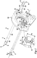
- Fig. 1 show two bolts according to embodiments of the present invention
- Fig. 2 show a cross section view of a rock drill according to embodiments of the invention.
- Fig. 1 show a first and a second bolt 2 according to embodiments of the present invention.
- the two bolts 2 are of same type.
- some of the references in Fig. 1 refers to the first bolt 2 and some to the second bolt 2. In the description below will reference be made solely to the bolt 2.
- the bolt 2 comprises an elongated body 4 with a central axis C.
- the bolt 2 is made of quenched and tempered steel.
- the elongated body 4 is in a first end 6 provided with a first thread 8 and in a second end 10 provided with a second thread 12.
- the first thread 8 and the second thread 12 are rolled threads.
- Between the first end 6 and the second end 10 is an intermediate part 14 of the elongated body 4 arranged.
- the intermediate part 14 is provided with a collar 16.
- the collar 16 is provided with a first flat surface 18 and a second flat surface 20.
- the first flat surface 18 extends substantially in parallel with the central axis C.
- the second flat surface 20 is in parallel with the first flat surface 18.
- the collar 16 is designed in a homogenous piece together with the elongated body 4.
- a transition from the elongated body to the collar has a radius r, which radius r is 1,5 - 5 mm.
- the first thread 8 has a first diameter d 1 .
- the second thread 12 has a second diameter d 2 .
- the second diameter d 2 may be within the interval of 0,8 - 1,2 multiplied with first the diameter d 1 .
- the second diameter d 2 is the same as the first diameter d 1 .
- the collar 16 extends a first distance L along with the central axis C.
- the first distance L may be of a length within the interval of 0,5 - 3 multiplied with first the diameter d 1 .
- the collar 16 has a first cylindrical surface part 22 and a second cylindrical surface part 24.
- the first and the second cylindrical surface parts 22, 24 are substantially in parallel with the central axis C.
- a distance between the first and the second cylindrical surface parts 22, 24 constitutes a third diameter d 3 .
- the third diameter d 3 may be within the interval of 1,5 - 3 multiplied with the first diameter d 1 .
- the third diameter d 3 about 1,8 multiplied with first the diameter d 1 .
- a distance between the first flat surface 18 and the second flat surface 20 may be within the interval of 1,2 - 2,5 multiplied with first the diameter d 1 .
- In the present embodiments are the distance about 1,5 multiplied with first the diameter d 1 .
- the elongated body 4 comprises a first cylindrical support surface 26 adjacent to the first thread 8, and a second cylindrical support surface 28 adjacent to the second thread 12.
- the central axis for the first and the second cylindrical support surface 22, 24 coincides with the central axis C for the elongated body 4.
- the central axis C is the elongated body 4 from the first end 6 consecutively provided with the first thread 8, the first cylindrical support surface 26 and a first elongated part 30.
- the first elongated part 30 has a diameter less than the first cylindrical support surface 26.
- the second elongated part 32 has a diameter less than the second cylindrical support surface 28.
- Fig. 2 shows a view of a rock drill 40 according to embodiments of the invention.
- the rock drill 40 comprises a machine housing 42 for housing and bear mounting of e.g. an impact piston 44 and a neck adapter 46.
- the machine housing 42 comprises e.g. a first part of the housing 48, a second part of the housing 50 and a third part of the housing 52.
- the first housing part 48 is arranged on a first side 54 of the second housing part 50 and the third housing part 52 is arranged on a second side 56 of the second housing part 50.
- the first housing part 48, the second housing part 50 and the third housing part 52 are hold together by two bolts 2 according to any of the aspects or the embodiments described herein.
- this embodiment are another two housing parts hold together by the two bolts 2.
- the other two housing parts are arranged between the first housing part 48 and the second housing part 50.
- the second housing part 50 is provided with a seat 58, see also Fig. 1 .
- the seat 58 is the collar 16 of each bolt 2 arranged rotationally fixed by at least partly abut between the first flat surface 18 of the collar 16 and a first flat seat surface 60 of the seat 58.
- the first flat seat surface 60 of the seat 58 extends substantially in parallel with the central axis C of the bolt 2.
- the first flat surface 18 is thus arranged to abut a surface of the seat 58 for rotational fixation of the bolt 2.
- the second flat surface 20 of the collar 16 at least partly abut a flat surface of the seat 58, namely a second flat seat surface 62, and thereby contributes to the rotational fixation of the bolt 2.
- Each bolt 2 extends through the second housing part 50.
- the second housing part 50 is thus provided with two through holes for this purpose.
- Each seat 58 consists in part of respective through hole.
- the seat 58 is arranged in connection with the second side 56 of the second housing part 50.
- the collar 16 at least partly abut the second housing part 50 in the seat 58 at a first level 64.
- the first level 64 extends substantially perpendicular to the central axis C of the bolt 2.
- the seat 58 constitutes a resistance to the collar 16 when the first housing part 48 and the further two housing parts biased together by the bolt 2 towards the second housing part 50, from/towards the first side 54 of the second housing part 50.
- the first housing part 48 is biased, by the two bolts 2, between a first nut 66 arranged on the first thread 8, and the second housing part 50.
- the collar 16 constitutes, in the seat 58, a resistance to the first bolt 66 in a direction along the central axis C.
- the third housing part 52 is the third housing part 52, from/towards the second side 56 of the second housing part 50, by the bolt 2 biased between the second housing part 50 and a second nut 68 arranged on the second thread 12.
- the first bolt 66 constitutes a resistance in the direction along the central axis C.
- the third housing part 52 may thus be loosened from the second housing part 50 by that the second bolt 68 is loosened, without need to loosen the housing part 48 from the second housing part 50.
- the elongated body 4 extends, in direction from the first level 64 to the first end 6 of the bolt 2, radially without contact through the second housing part 50.
- the rotational fixation of the bolt 2 in the second housing part 50 is thus achieved by contact between the periphery of the collar 16 and the second housing part 50.
- the first cylindrical support surface 26 at least partly radially abut the first housing part 48 and the second cylindrical support surface 28 at least partly radially abut the third housing part 52.
- the first and the second support surfaces 26, 38 may thus constitute guiding elements of the first and the third housing parts 48, 52, respectively.
- the collar 16 may be provided with solely one first flat surface 16.
- the collar 16 may alternatively be provided with more than two flat surfaces, for example four, six or eight flat surfaces.
Landscapes
- Engineering & Computer Science (AREA)
- Mechanical Engineering (AREA)
- General Engineering & Computer Science (AREA)
- Geology (AREA)
- Life Sciences & Earth Sciences (AREA)
- Mining & Mineral Resources (AREA)
- Environmental & Geological Engineering (AREA)
- Fluid Mechanics (AREA)
- General Life Sciences & Earth Sciences (AREA)
- Geochemistry & Mineralogy (AREA)
- Physics & Mathematics (AREA)
- Earth Drilling (AREA)
- Percussive Tools And Related Accessories (AREA)
Description
- The present invention relates to a bolt and a rock drill with a housing comprising housing parts hold together by a bolt.
- In a certain type of rock drill, housing parts are hold together by bolts with threads in both ends of the bolts and an eccentric collar, which enables a part of the housing to be demounted while the second housing parts are hold together. The eccentric collar constitutes a basis for an axial biasing force. The eccentric collar locks the bolt in rotational direction in a part of the housing together with a cylindrical surface of the bolt closest to the collar. Thereby may a nut be loosened at the same time as biasing of the other housing parts is maintained.
- When the eccentric collar together with the cylindrical surface of the bolt locks the bolt in rotational direction large normal forces occurs in contact points; between the cylindrical surface of the bolt and the housing part, respective between the eccentric collar and the housing part. This cause wear damages on the cylindrical surface of the bolt when the rock drill vibrates during operation. These wear damages may initiate fatigue cracks causing fracture of the bolt.
- A bolt for holding housing parts of a rock drill is disclosed in
US 2010/0059280 A1 . A fastener for holding housing parts is disclosed inUS 4681496 A1 . - An object of the present invention is to provide a bolt for holding together housing parts in a rock drill, which bolt has a good resistance to wear damages and fatigue fracture. This object is achieved according to one aspect of the invention by a bolt comprising an elongated body with a central axis, which elongated body in a first end is provided with a first thread and in a second end is provided with a second thread. An intermediate part of the elongated body between the first end and the second end is provided with a collar. The collar is provided with at least a first flat surface, which first flat surface extends substantially in parallel with the central axis.
- Since the collar is provided with at least a first flat surface, which first flat surface extends substantially in parallel with the central axis, the bolt may be fixed against rotation in that the first flat surface abuts for example a part of the housing of a rock drilling machine. The elongated body of the bolt need not abut any part of the housing to achieve rotational fixation of the bolt in the housing part. The normal forces occurring on the cylindrical surface of the elongated body of a bolt with eccentric collar according to prior art may thereby be avoided. Thus, the above mentioned purpose is achieved.
- The bolt may be designed such that the elongated body is of a different diameter along with the bolt. The bolt may be designed such that the collar is the part of the bolt with the largest diameter. The collar may extend radially perpendicular outwards from the central axis. The intermediate part of the bolt being provided with the collar need not be centrally arranged along the central axis of bolt but may for example be arranged closer to the second end of the bolt than to the first end of the bolt. Thus, the placement of the collar on the bolt may be depending on the number of and the size of the housing parts of a rock drill to be hold together by the bolt.
- According to embodiments may the first flat surface be arranged to abut a surface for rotational fixation of the bolt. Thereby may a more advantageous abut between a part of the bolt and for example a part of the housing of a rock drill be achieved than at known bolts with eccentric collar, thus, unfavorable normal forces may result in wear in contact points between the cylindrical surface of the bolt and the housing part, respective between the eccentric collar and the housing part may be avoided.
- According to embodiments, the first thread has a first diameter, and the collar extends a first distance along with the central axis. The first distance may have a length within the interval of 0,5 - 3 multiplied with first the diameter. Thereby the collar, and thereby also the first flat surface, may have an extension large enough to obtain a surface large enough to distribute forces that may occur at rotational fixation of the bolt. Further, thereby may a collar of a size large enough to capture shearing forces along with the central axis be achieved, forces occurring when holding together housing parts of a rock drilling machine.
- According to embodiments, the second thread may have a second diameter, and the second diameter may be within the interval of 0,8 - 1,2 multiplied with first the diameter.
- According to embodiments, the collar has a first cylindrical part surface and a second cylindrical part surface. The first and second cylindrical part surfaces may be substantially in parallel with the central axis. A distance between the first and the second cylindrical part surface constitutes a third diameter. The third diameter may be within the interval of 1,5 - 3 multiplied with first the diameter. Thereby, a collar with a cross section of a size for absorbing of forces along the central axis of the bolt may be achieved. The first cylindrical part surface and the second cylindrical part surface may be arranged in direct connection to each other, or may be separated from each other by the first flat surface and another at least one flat surface.
- According to embodiments, the collar may be provided with a second flat surface, which second flat surface may be in parallel with the first flat surface. Thereby, two surfaces for distributing the forces that may occur at rotational fixation of the bolt may be achieved.
- According to embodiments, a distance between the first flat surface and the second flat surface may be within the interval of 1,2 - 2,5 multiplied with first the diameter. Thereby, a collar with a cross section of a size enough to absorb forces along the central axis of the bolt may be achieved. Further, a collar of a size large enough to be able to absorb shear forces along with the central axis is achieved.
- According to embodiments, the collar may be designed in a homogenous piece together with the elongated body. Thereby, the collar may constitute a fixed resistance to forces along with the central axis.
- According to embodiments, a transition from the elongated body to the collar may have a radius, which radius is 1,5 - 5 mm. Thereby, the risk for cracking at the transition between the elongated body and the collar is minimized.
- According to embodiments, the elongated body may comprise a first cylindrical support surface adjacent to the first thread, and a second cylindrical support surface adjacent to the second thread. Thereby may for example housing parts of a rock drill be positioned in relation to the first and to the second thread by abutting the first and the second support surface.
- According to embodiments, the elongated body may, along the central axis from the first end, consecutively be provided with the first thread, the first cylindrical support surface and a first elongated part, which first elongated part may have a diameter less than the first cylindrical support surface. The elongated body may, along the central axis from the second end, consecutively be provided with the second thread, the second cylindrical support surface and a second elongated part, which second elongated part may have a diameter less than the second cylindrical support surface. Thanks to the less diameter in respective first and second elongated parts, vibrations along the central axis of the bolt will be of a less tension amplitude than the in a bolt with first and second elongated parts of the same thickness diameter as the first and second cylindrical support surfaces. The time period before a fatigue fracture increases with decreasing tension amplitude, and thereby the lifetime of the bolt increases.
- According to embodiments, the first thread and the second thread may be rolled threads. Rolled threads are made by threads milled in in the bolt, in contrast to cut threads. In this way a bolt with strong threads is achieved.
- According to embodiments, the bolt may be made of quenched and tempered steel. Thereby may a bolt of strength suitable for, as for example, holding together housing parts of a rock drill be achieved.
- Another object of the present invention is to provide a rock drill, in which housing parts of a machine housing of the rock drill are hold together in a reliable way.
- This object is, according to one aspect of the invention, achieved by a rock drill comprising a machine housing for housing and bear mounting of an impact piston and a neck adapter. The machine housing comprises a first housing part, a second housing part and a third housing part. The first housing part is arranged on a first side of the second housing part, and the third housing part is arranged on a second side of the second housing part. The first housing part, the second housing part and the third housing part are hold together by at least the bolt according to any of the aspects or the embodiments described herein. The second housing part is provided with a seat, in which seat the collar of the bolt is arranged rotationally fixed by at least partly abut between the first flat surface of the collar and a first flat seat surface of the seat, which first flat seat surface extends substantially in parallel with the central axis of the bolt.
- Since the bolt according to aspects and embodiments described herein uses, and the second housing part is provided with, a seat in which the first flat surface of the collar abut the first flat seat surface, the bolt is rotationally fixed in a way achieving good resistance to wear damages and fatigue fracture of the bolt when the housing parts of the rock drill are hold together. Thus, the above mentioned purpose is achieved.
- According to embodiments, the bolt extends through the second housing part, and the seat is arranged in connection with the second side of the second housing part. The collar may at least partly abut the second housing part in the seat in a first level, which first level extends substantially perpendicular to the central axis of the bolt. Thereby, housing parts of the machine housing of the rock drill may be biased together by the bolt in that the seat in the second housing part constitutes a resistance to the collar.
- According to embodiments, the elongated body may extend, in direction from the first flat surface towards the first end of the bolt, radially without contact through the second housing part. Thereby, no normal forces occurs between the elongated body of the bolt and the second housing part when the bolt is rotationally fixed in the second housing part by abut between the first flat the surface of the collar and the first flat seat surface. Thereby, wear damages on the cylindrical surface of the bolt may be avoided when the rock drill vibrates during operation. Thus, only at the periphery of the collar the rotational fixation is achieved, and it is therefore mainly the periphery of the collar that is in contact with the second housing part. Since the collar has larger diameter than the elongated body, any wear damages on this part of the bolt do not have any significance for the strength of the bolt related to holding together the housing parts.
- According to embodiments, the first housing part may be biased, by the bolt, between a first nut arranged on the first thread and the second housing part, in which second part of the housing the collar in the seat constitutes a resistance to the first bolt in a direction along the central axis. The third housing part may be biased, by the bolt, between the second housing part and a second nut arranged on the second thread, to which second nut the first bolt constitutes a resistance in the direction along the central axis.
- According to embodiments may the first cylindrical the support surface at least partly radially abut the first housing part and it second cylindrical the support surface at least partly radially abut the third housing part.
- Other features and advantages for the present invention appear from the attached claims and the following detailed the description. The skilled person within the field realizes that different features of the invention may be combined to create other embodiments than the described below, without deviating from the scope of protection of the present invention as defined by the attached claims.
- Different approaches to the invention, including special features and advantages, appear from the following detailed description and the associated drawings, in which:
Fig. 1 show two bolts according to embodiments of the present invention, and
Fig. 2 show a cross section view of a rock drill according to embodiments of the invention. - The present invention is described more in detail below with reference to the attached drawings, in which example of embodiments is shown. The invention shall not be interpreted to be limited to the described examples of embodiments. Like numbers in the drawings relate throughout to like elements. For simplicity may not necessarily well-known functions and designs be described in detail.
-
Fig. 1 show a first and asecond bolt 2 according to embodiments of the present invention. The twobolts 2 are of same type. For clarity reasons some of the references inFig. 1 refers to thefirst bolt 2 and some to thesecond bolt 2. In the description below will reference be made solely to thebolt 2. - The
bolt 2 comprises anelongated body 4 with a central axis C. Thebolt 2 is made of quenched and tempered steel. Theelongated body 4 is in a first end 6 provided with afirst thread 8 and in asecond end 10 provided with asecond thread 12. Thefirst thread 8 and thesecond thread 12 are rolled threads. Between the first end 6 and thesecond end 10 is anintermediate part 14 of theelongated body 4 arranged. Theintermediate part 14 is provided with acollar 16. - The
collar 16 is provided with a firstflat surface 18 and a secondflat surface 20. The firstflat surface 18 extends substantially in parallel with the central axis C. The secondflat surface 20 is in parallel with the firstflat surface 18. Thecollar 16 is designed in a homogenous piece together with theelongated body 4. A transition from the elongated body to the collar has a radius r, which radius r is 1,5 - 5 mm. - The
first thread 8 has a first diameter d1. Thesecond thread 12 has a second diameter d2. The second diameter d2 may be within the interval of 0,8 - 1,2 multiplied with first the diameter d1. In the present embodiments is the second diameter d2 the same as the first diameter d1. Thecollar 16 extends a first distance L along with the central axis C. The first distance L may be of a length within the interval of 0,5 - 3 multiplied with first the diameter d1. In the present embodiments is the first distance L about the same as the first diameter d1. - The
collar 16 has a firstcylindrical surface part 22 and a secondcylindrical surface part 24. The first and the secondcylindrical surface parts cylindrical surface parts flat surface 18 and the secondflat surface 20 may be within the interval of 1,2 - 2,5 multiplied with first the diameter d1. In the present embodiments are the distance about 1,5 multiplied with first the diameter d1. - The
elongated body 4 comprises a firstcylindrical support surface 26 adjacent to thefirst thread 8, and a secondcylindrical support surface 28 adjacent to thesecond thread 12. The central axis for the first and the secondcylindrical support surface elongated body 4. Along the central axis C is theelongated body 4 from the first end 6 consecutively provided with thefirst thread 8, the firstcylindrical support surface 26 and a firstelongated part 30. The firstelongated part 30 has a diameter less than the firstcylindrical support surface 26. Along the central axis C from thesecond end 10 is theelongated body 4 consecutively provided with thesecond thread 12, the secondcylindrical support surface 28 and a secondelongated part 32. The secondelongated part 32 has a diameter less than the secondcylindrical support surface 28. -
Fig. 2 shows a view of arock drill 40 according to embodiments of the invention. Therock drill 40 comprises amachine housing 42 for housing and bear mounting of e.g. animpact piston 44 and aneck adapter 46. Themachine housing 42 comprises e.g. a first part of thehousing 48, a second part of thehousing 50 and a third part of thehousing 52. Thefirst housing part 48 is arranged on afirst side 54 of thesecond housing part 50 and thethird housing part 52 is arranged on asecond side 56 of thesecond housing part 50. - The
first housing part 48, thesecond housing part 50 and thethird housing part 52 are hold together by twobolts 2 according to any of the aspects or the embodiments described herein. In this embodiment are another two housing parts hold together by the twobolts 2. The other two housing parts are arranged between thefirst housing part 48 and thesecond housing part 50. Thesecond housing part 50 is provided with aseat 58, see alsoFig. 1 . In theseat 58 is thecollar 16 of eachbolt 2 arranged rotationally fixed by at least partly abut between the firstflat surface 18 of thecollar 16 and a first flat seat surface 60 of theseat 58. The first flat seat surface 60 of theseat 58 extends substantially in parallel with the central axis C of thebolt 2. The firstflat surface 18 is thus arranged to abut a surface of theseat 58 for rotational fixation of thebolt 2. Also the secondflat surface 20 of thecollar 16 at least partly abut a flat surface of theseat 58, namely a secondflat seat surface 62, and thereby contributes to the rotational fixation of thebolt 2. - The continued description refers both to
Fig. 1 and2 . Eachbolt 2 extends through thesecond housing part 50. Thesecond housing part 50 is thus provided with two through holes for this purpose. Eachseat 58 consists in part of respective through hole. Theseat 58 is arranged in connection with thesecond side 56 of thesecond housing part 50. Thecollar 16 at least partly abut thesecond housing part 50 in theseat 58 at afirst level 64. Thefirst level 64 extends substantially perpendicular to the central axis C of thebolt 2. - The
seat 58 constitutes a resistance to thecollar 16 when thefirst housing part 48 and the further two housing parts biased together by thebolt 2 towards thesecond housing part 50, from/towards thefirst side 54 of thesecond housing part 50. Thus, thefirst housing part 48 is biased, by the twobolts 2, between afirst nut 66 arranged on thefirst thread 8, and thesecond housing part 50. In thesecond housing part 50 thecollar 16 constitutes, in theseat 58, a resistance to thefirst bolt 66 in a direction along the central axis C. In a corresponding way is thethird housing part 52, from/towards thesecond side 56 of thesecond housing part 50, by thebolt 2 biased between thesecond housing part 50 and asecond nut 68 arranged on thesecond thread 12. For thesecond nut 68, thefirst bolt 66 constitutes a resistance in the direction along the central axis C. Thethird housing part 52 may thus be loosened from thesecond housing part 50 by that thesecond bolt 68 is loosened, without need to loosen thehousing part 48 from thesecond housing part 50. - The
elongated body 4 extends, in direction from thefirst level 64 to the first end 6 of thebolt 2, radially without contact through thesecond housing part 50. The rotational fixation of thebolt 2 in thesecond housing part 50 is thus achieved by contact between the periphery of thecollar 16 and thesecond housing part 50. The firstcylindrical support surface 26 at least partly radially abut thefirst housing part 48 and the secondcylindrical support surface 28 at least partly radially abut thethird housing part 52. The first and the second support surfaces 26, 38 may thus constitute guiding elements of the first and thethird housing parts - The skilled person within the field realizes that the embodiments described above may be combined. Different modifications are obvious for the skilled person. For example, the
collar 16 may be provided with solely one firstflat surface 16. Thecollar 16 may alternatively be provided with more than two flat surfaces, for example four, six or eight flat surfaces. Each of the twobolts 2, suitable for holding together housing parts of adrilling machine 40 according to embodiments, may have the following size, which size only is quoted in exemplifying purpose: d1 = 20 mm, d2 = 20 mm, d3 = 36 mm, L = 18 mm, a = 30 mm. - Thus, the invention is not limited to the described embodiments. The invention is solely limited by the scope of protection defined by the patent claims.
Claims (15)
- A bolt (2) for holding together housing parts in a rock drill, the bolt (2) comprising an elongated body (4) with a central axis (C), which elongated body (4) in a first end (6) is provided with a first thread (8) and in a second end (10) is provided with a second thread (12), wherein an intermediate part (14) between the first end (6) and the second end (10) of the elongated body (4) is provided with a collar (16),
wherein the collar (16) is provided with at least one first flat surface (18), which first flat surface (18) extends substantially in parallel with the central axis (C), and wherein the elongated body (4) along the central axis (C) from the first end (6) consecutively is provided with the first thread (8), a first cylindrical support surface (26) and a first elongated part (30), which first elongated part (30) has a diameter less than the first cylindrical support surface (26), and wherein the elongated body (4) along the central axis (C) from the second end (10) consecutively is provided with the second thread (12), a second cylindrical support surface (28) and a second elongated part (32), which second elongated part (32) has a diameter less than the second cylindrical support surface (28). - The bolt (2) according to claim 1, wherein the first flat surface (18) is arranged to abut a flat seat surface (60) of a housing part (50) for rotational fixation of the bolt (2).
- The bolt (2) according to claim 1 or 2, wherein the first thread (8) has a first diameter (d1), and wherein the collar (16) extends a first distance (L) along with the central axis (C), which first distance (L) is of a length within the interval of 0,5 - 3 multiplied with the first diameter (d1).
- The bolt (2) according to claim 3, wherein the second thread (12) has a second diameter (d2), and wherein the second diameter (d2) is within the interval of 0,8 - 1,2 multiplied with the first diameter (d1).
- The bolt (2) according to claims 3 or 4, wherein the collar (16) has a first cylindrical surface part (22) and a second cylindrical surface part (24), which first and second cylindrical surface parts (22, 24) are substantially in parallel with the central axis (C), and wherein a distance between the first and the second cylindrical surface part (22, 24) constitutes a third diameter (d3), which third diameter (d3) is within the interval of 1,5 - 3 multiplied with the first diameter (d1).
- The bolt (2) according to any of the preceding claims, wherein the collar (16) is provided with a second flat surface (20), which second flat surface (20) is in parallel with the first flat surface (18).
- The bolt (2) according to claim 6 and any of the claims 3 - 5, wherein a distance (a) between the first flat surface (18) and the second flat surface (20) is within the interval of 1,2 - 2,5 multiplied with the first diameter (d1).
- The bolt (2) according to any of the preceding claims, wherein the collar (16) is designed in a homogenous piece together with the elongated body (4).
- The bolt (2) according to claim 8, wherein a transition from the elongated body (4) to the collar (16) has a radius (r), which radius (r) is 1,5 - 5 mm.
- The bolt (2) according to any of the preceding claims, wherein the elongated body (4) comprises the first cylindrical support surface (26) adjacent to the first thread (8) and the second cylindrical support surface (28) adjacent to the second thread (12).
- A rock drill (40) comprising a machine housing (42) for housing and bear mounting of an impact piston (44) and a neck adapter (46), which machine housing (42) comprises a first housing part (48), a second housing part (50) and a third housing part (52), wherein the first housing part (48) is arranged on a first side (54) of the second housing part (50) and the third housing part (52) is arranged on a second side (56) of the second housing part (50),
characterized in that the first housing part (48), the second housing part (50) and the third housing part (52) are hold together by at least one bolt (2) according to any of the claims 1 - 10, wherein the second housing part (50) is provided with a seat (58), in which seat (58) the collar (16) of the bolt (2) is rotationally fixed arranged by abut at least partly between the first flat surface (18) of the collar (16) and a first flat seat surface (60) of the seat (58), which first flat seat surface (60) extends substantially in parallel with the central axis of the bolt (2). - The rock drill (40) according to claim 11, wherein the bolt (2) extends through the second housing part (50), and the seat (58) is arranged in connection with the second side (56) of the second housing part (50), and wherein the collar (16) at least partly abut the second housing part (50) in the seat (58) in a first level (64), which first level (64) extends substantially perpendicular to the central axis (C) of the bolt (2).
- The rock drill (40) according to claim 12, wherein the elongated body (4) extends, in direction from the first level (64) towards the first end (6) of the bolt (2), radially contact free through the second housing part (50).
- The rock drill (40) according to claim 12 or 13, wherein the first housing part (48) is biased, by the bolt (2), between a first nut (66) arranged on the first thread (8) and the second housing part (50), in which second housing part (50) the collar (16) in the seat (58) constitutes a resistance to the first nut (66) in a direction along the central axis (C), and wherein the third housing part (52) is biased, by the bolt (2), between the second housing part (50) and a second nut (68) arranged on the second thread (12), to which second nut (68) the first nut (66) constitutes a resistance in the direction along the central axis (C).
- The rock drill (40) according to any of the claims 11 - 14, wherein the first cylindrical support surface (26) at least partly radially abut the first housing part (48) and the second cylindrical support surface (28) at least partly radially abut the third housing part (52).
Applications Claiming Priority (2)
| Application Number | Priority Date | Filing Date | Title |
|---|---|---|---|
| SE1350089A SE537124C2 (en) | 2013-01-28 | 2013-01-28 | Bolt and rock drill with bolt |
| PCT/SE2014/050092 WO2014116174A1 (en) | 2013-01-28 | 2014-01-27 | Bolt, and rock drill with bolt |
Publications (3)
| Publication Number | Publication Date |
|---|---|
| EP2948686A1 EP2948686A1 (en) | 2015-12-02 |
| EP2948686A4 EP2948686A4 (en) | 2016-09-28 |
| EP2948686B1 true EP2948686B1 (en) | 2017-11-01 |
Family
ID=51227860
Family Applications (1)
| Application Number | Title | Priority Date | Filing Date |
|---|---|---|---|
| EP14743283.5A Active EP2948686B1 (en) | 2013-01-28 | 2014-01-27 | Bolt, and rock drill with bolt |
Country Status (11)
| Country | Link |
|---|---|
| US (1) | US10030687B2 (en) |
| EP (1) | EP2948686B1 (en) |
| JP (1) | JP6296666B2 (en) |
| CN (1) | CN104956099B (en) |
| AU (1) | AU2014210399B2 (en) |
| CA (1) | CA2899315C (en) |
| ES (1) | ES2656268T3 (en) |
| NO (1) | NO2948686T3 (en) |
| SE (1) | SE537124C2 (en) |
| WO (1) | WO2014116174A1 (en) |
| ZA (1) | ZA201504853B (en) |
Families Citing this family (1)
| Publication number | Priority date | Publication date | Assignee | Title |
|---|---|---|---|---|
| SE537124C2 (en) * | 2013-01-28 | 2015-01-27 | Atlas Copco Rock Drills Ab | Bolt and rock drill with bolt |
Family Cites Families (43)
| Publication number | Priority date | Publication date | Assignee | Title |
|---|---|---|---|---|
| US3505831A (en) * | 1968-07-05 | 1970-04-14 | Skil Corp | Flexible shaft coupler |
| JPS49101760A (en) * | 1973-02-02 | 1974-09-26 | ||
| JPS5818123U (en) * | 1981-07-30 | 1983-02-04 | 新日本製鐵株式会社 | Screw fasteners with excellent breakage resistance |
| US4548279A (en) * | 1983-07-29 | 1985-10-22 | Wenzel Zaruba | Tool extractor |
| JPS6062608U (en) * | 1983-10-06 | 1985-05-01 | 宇部興産株式会社 | Bolt joint equipment |
| US4681496A (en) * | 1984-06-28 | 1987-07-21 | Fasolino Gabriel V | Reusable and adjustable fastener for use with power tool applicator |
| JP2536757Y2 (en) * | 1986-10-14 | 1997-05-28 | 武蔵精密工業株式会社 | Connection structure between ball joint and stabilizer |
| US4863329A (en) * | 1988-01-29 | 1989-09-05 | United Technologies Corporation | Resiliently clamped support |
| US5170551A (en) * | 1988-10-24 | 1992-12-15 | Ovako Steel Couplings Ab | Alignment of shaft flanges |
| JPH0326812U (en) * | 1989-07-27 | 1991-03-19 | ||
| JPH0586012U (en) * | 1992-04-23 | 1993-11-19 | 石川島播磨重工業株式会社 | Bolt fastening structure |
| US5603592A (en) * | 1994-10-03 | 1997-02-18 | Huck International, Inc. | High strength blind bolt with uniform high clamp over an extended grip range |
| FR2746710B1 (en) * | 1996-03-26 | 1998-07-17 | Hutchinson | FLAT ROLLING DEVICE FOR A MOTOR VEHICLE AND ITS MOUNTING METHOD |
| US6341917B1 (en) * | 1998-12-30 | 2002-01-29 | Emhart Inc. | Double ended stud fastening system |
| SE515890C2 (en) * | 2000-11-02 | 2001-10-22 | Atlas Copco Rock Drills Ab | rock Drill |
| DE10102308A1 (en) * | 2001-01-19 | 2002-07-25 | Hilti Ag | Rotary-percussive rockdrill with flushing bore uses symmetrically placed driver grooves larger than residual web round smooth cylindrical shaft for increased torque and percussion rate. |
| JP4592979B2 (en) | 2001-02-23 | 2010-12-08 | 株式会社栗本鐵工所 | Fastening method of brake disks for railway vehicles |
| US6503038B2 (en) * | 2001-03-30 | 2003-01-07 | The United States Of America As Represented By The Secretary Of The Army | Reduced shank external flow passage bolt with integral pilot |
| US7677852B2 (en) * | 2004-08-30 | 2010-03-16 | Acument Intellectual Properties, Llc | Multi-lobular lockbolt |
| US7677853B2 (en) * | 2004-08-30 | 2010-03-16 | Acument Intellectual Properties, Llc | Multi-lobular lockbolt and system |
| WO2006039412A2 (en) * | 2004-09-29 | 2006-04-13 | Trufast Corporation | Fastener having a removable drill tip and method |
| FR2877046B1 (en) * | 2004-10-26 | 2010-09-24 | Snecma Moteurs | TURBOMACHINE WITH DECOUPLING DEVICE AND FUSE SCREW FOR TURBOMACHINE DECOUPLING DEVICE |
| US7607491B2 (en) * | 2006-03-15 | 2009-10-27 | Integrated Tool Solutions Llc | Jackhammer lift assist |
| JP2009533228A (en) * | 2006-03-15 | 2009-09-17 | インテグレイテッド ツール ソリューションズ, エルエルシー | Jack hammer with lifting assistance |
| US8579033B1 (en) * | 2006-05-08 | 2013-11-12 | Mako Rentals, Inc. | Rotating and reciprocating swivel apparatus and method with threaded end caps |
| AU2007214343B2 (en) * | 2007-08-31 | 2009-08-13 | Sandvik Intellectual Property Ab | Rock bolt with mechanical anchor |
| US7896103B2 (en) * | 2008-02-04 | 2011-03-01 | Ingersoll Rand Company | Power tool housing support structures |
| CN102057129B (en) * | 2008-06-03 | 2014-10-15 | 阿特拉斯·科普柯凿岩设备有限公司 | Arrangement and method comprising a flushing head for a rock drilling machine, and rock drilling machine comprising the arrangement |
| US8371397B2 (en) | 2008-09-05 | 2013-02-12 | Longyear Tm, Inc. | Feed mechanism for drilling systems |
| WO2010090736A1 (en) * | 2009-02-04 | 2010-08-12 | Espinosa Thomas M | Concrete anchor |
| FR2943746B1 (en) * | 2009-03-27 | 2011-06-03 | Hutchinson | TIGHTENING COLLAR AND FLAT ROLLING DEVICE INCORPORATING IT |
| SE534450C2 (en) | 2009-07-01 | 2011-08-30 | Atlas Copco Rock Drills Ab | Device and method for protecting a rock drill against corrosion attack |
| CN201460720U (en) * | 2009-08-06 | 2010-05-12 | 河北宏远液压机械有限公司 | Automatic hydraulic backhander rock drill |
| JP2011078993A (en) * | 2009-10-05 | 2011-04-21 | Sanmei Seisakusho:Kk | Form rolling die and method for form-rolling bolt with profile |
| US8312936B2 (en) * | 2010-02-04 | 2012-11-20 | Robert Bosch Gmbh | Lockout apparatus for protecting an attachment device mounted on rotary power tools |
| CN201771920U (en) * | 2010-08-18 | 2011-03-23 | 浙江捷能汽车零部件有限公司 | Stud bolt |
| SE535149C2 (en) * | 2010-08-31 | 2012-05-02 | Atlas Copco Rock Drills Ab | Hydraulic percussion for use in rock or concrete cutting equipment |
| JP2012076164A (en) * | 2010-09-30 | 2012-04-19 | Nippon Pneumatic Mfg Co Ltd | Fastening device of through-bolt in impact-driven tool |
| EP2604872B1 (en) * | 2011-12-12 | 2015-02-25 | AGUSTAWESTLAND S.p.A. | Lock ring and threaded stud |
| SE537124C2 (en) * | 2013-01-28 | 2015-01-27 | Atlas Copco Rock Drills Ab | Bolt and rock drill with bolt |
| US8894329B1 (en) * | 2013-05-31 | 2014-11-25 | Climb Tech, LLC. | Wedge anchor bolt |
| TW201529251A (en) * | 2014-01-16 | 2015-08-01 | Basso Ind Corp | An assembling structure of pneumatic tool and assembling method therefor |
| US20170197604A1 (en) * | 2016-01-13 | 2017-07-13 | Bachouchi Mr Malik | Pre-Pressurized adaptive Banjo-Bolt Accumulator Valve For Hydraulic Brake Systems and Method |
-
2013
- 2013-01-28 SE SE1350089A patent/SE537124C2/en unknown
-
2014
- 2014-01-27 CN CN201480005986.XA patent/CN104956099B/en active Active
- 2014-01-27 EP EP14743283.5A patent/EP2948686B1/en active Active
- 2014-01-27 WO PCT/SE2014/050092 patent/WO2014116174A1/en active Application Filing
- 2014-01-27 US US14/651,308 patent/US10030687B2/en active Active
- 2014-01-27 AU AU2014210399A patent/AU2014210399B2/en active Active
- 2014-01-27 JP JP2015555129A patent/JP6296666B2/en active Active
- 2014-01-27 ES ES14743283.5T patent/ES2656268T3/en active Active
- 2014-01-27 NO NO14743283A patent/NO2948686T3/no unknown
- 2014-01-27 CA CA2899315A patent/CA2899315C/en active Active
-
2015
- 2015-07-06 ZA ZA2015/04853A patent/ZA201504853B/en unknown
Non-Patent Citations (1)
| Title |
|---|
| None * |
Also Published As
| Publication number | Publication date |
|---|---|
| US10030687B2 (en) | 2018-07-24 |
| CN104956099A (en) | 2015-09-30 |
| SE537124C2 (en) | 2015-01-27 |
| EP2948686A1 (en) | 2015-12-02 |
| SE1350089A1 (en) | 2014-07-29 |
| AU2014210399B2 (en) | 2017-06-29 |
| US20150330433A1 (en) | 2015-11-19 |
| CN104956099B (en) | 2017-06-20 |
| JP2016509656A (en) | 2016-03-31 |
| CA2899315A1 (en) | 2014-07-31 |
| ES2656268T3 (en) | 2018-02-26 |
| EP2948686A4 (en) | 2016-09-28 |
| ZA201504853B (en) | 2016-10-26 |
| JP6296666B2 (en) | 2018-03-20 |
| CA2899315C (en) | 2021-01-12 |
| NO2948686T3 (en) | 2018-03-31 |
| AU2014210399A1 (en) | 2015-07-30 |
| WO2014116174A1 (en) | 2014-07-31 |
Similar Documents
| Publication | Publication Date | Title |
|---|---|---|
| AU2018102164A4 (en) | Tapered pick holder | |
| US9901988B2 (en) | Tool receptacle for a screw-in tool | |
| CA2760830C (en) | Drilling equipment and attachment means for the same | |
| JP2016526645A (en) | Fastening elements and fastening assemblies | |
| JP2015058530A (en) | Cutting tool | |
| US11187261B2 (en) | Liner bolt | |
| EP2379898A1 (en) | A locking plate to be used in a locking arrangement and such a locking arrangement | |
| EP2948686B1 (en) | Bolt, and rock drill with bolt | |
| US7469852B2 (en) | Load transference in grinding disks | |
| EP1610007A1 (en) | Tightening system for secure connection of at least two element with one another | |
| JP4701253B2 (en) | Bolt and fastener using the same | |
| KR101874004B1 (en) | Nut apparatus for hydraulic breaker | |
| US20170266669A1 (en) | Pick with limited tapered engagement | |
| WO2010089405A1 (en) | Coupling for a rotary tool | |
| JP2014101928A (en) | Spring-pin assembled bolt and its process of manufacture | |
| KR20090043277A (en) | Shearing bolt structure |
Legal Events
| Date | Code | Title | Description |
|---|---|---|---|
| PUAI | Public reference made under article 153(3) epc to a published international application that has entered the european phase |
Free format text: ORIGINAL CODE: 0009012 |
|
| 17P | Request for examination filed |
Effective date: 20150706 |
|
| AK | Designated contracting states |
Kind code of ref document: A1 Designated state(s): AL AT BE BG CH CY CZ DE DK EE ES FI FR GB GR HR HU IE IS IT LI LT LU LV MC MK MT NL NO PL PT RO RS SE SI SK SM TR |
|
| AX | Request for extension of the european patent |
Extension state: BA ME |
|
| DAX | Request for extension of the european patent (deleted) | ||
| A4 | Supplementary search report drawn up and despatched |
Effective date: 20160826 |
|
| RIC1 | Information provided on ipc code assigned before grant |
Ipc: F16B 39/28 20060101ALI20160822BHEP Ipc: F16B 33/00 20060101ALI20160822BHEP Ipc: B25F 5/02 20060101ALI20160822BHEP Ipc: F16B 35/04 20060101AFI20160822BHEP Ipc: B25D 17/00 20060101ALI20160822BHEP |
|
| GRAP | Despatch of communication of intention to grant a patent |
Free format text: ORIGINAL CODE: EPIDOSNIGR1 |
|
| INTG | Intention to grant announced |
Effective date: 20170622 |
|
| GRAS | Grant fee paid |
Free format text: ORIGINAL CODE: EPIDOSNIGR3 |
|
| GRAA | (expected) grant |
Free format text: ORIGINAL CODE: 0009210 |
|
| AK | Designated contracting states |
Kind code of ref document: B1 Designated state(s): AL AT BE BG CH CY CZ DE DK EE ES FI FR GB GR HR HU IE IS IT LI LT LU LV MC MK MT NL NO PL PT RO RS SE SI SK SM TR |
|
| REG | Reference to a national code |
Ref country code: GB Ref legal event code: FG4D |
|
| REG | Reference to a national code |
Ref country code: CH Ref legal event code: EP Ref country code: AT Ref legal event code: REF Ref document number: 942331 Country of ref document: AT Kind code of ref document: T Effective date: 20171115 |
|
| REG | Reference to a national code |
Ref country code: IE Ref legal event code: FG4D |
|
| REG | Reference to a national code |
Ref country code: DE Ref legal event code: R096 Ref document number: 602014016610 Country of ref document: DE |
|
| REG | Reference to a national code |
Ref country code: FR Ref legal event code: PLFP Year of fee payment: 5 |
|
| REG | Reference to a national code |
Ref country code: NO Ref legal event code: T2 Effective date: 20171101 |
|
| REG | Reference to a national code |
Ref country code: ES Ref legal event code: FG2A Ref document number: 2656268 Country of ref document: ES Kind code of ref document: T3 Effective date: 20180226 |
|
| REG | Reference to a national code |
Ref country code: NL Ref legal event code: MP Effective date: 20171101 |
|
| REG | Reference to a national code |
Ref country code: NO Ref legal event code: CHAD Owner name: EPIROC ROCK DRILLS AKTIEBOLAG, SE Ref country code: ES Ref legal event code: PC2A Owner name: EPIROC ROCK DRILLS AKTIEBOLAG Effective date: 20180319 |
|
| REG | Reference to a national code |
Ref country code: LT Ref legal event code: MG4D |
|
| PG25 | Lapsed in a contracting state [announced via postgrant information from national office to epo] |
Ref country code: SE Free format text: LAPSE BECAUSE OF FAILURE TO SUBMIT A TRANSLATION OF THE DESCRIPTION OR TO PAY THE FEE WITHIN THE PRESCRIBED TIME-LIMIT Effective date: 20171101 Ref country code: LT Free format text: LAPSE BECAUSE OF FAILURE TO SUBMIT A TRANSLATION OF THE DESCRIPTION OR TO PAY THE FEE WITHIN THE PRESCRIBED TIME-LIMIT Effective date: 20171101 Ref country code: NL Free format text: LAPSE BECAUSE OF FAILURE TO SUBMIT A TRANSLATION OF THE DESCRIPTION OR TO PAY THE FEE WITHIN THE PRESCRIBED TIME-LIMIT Effective date: 20171101 |
|
| REG | Reference to a national code |
Ref country code: AT Ref legal event code: HC Ref document number: 942331 Country of ref document: AT Kind code of ref document: T Owner name: EPIROC ROCK DRILLS AKTIEBOLAG, SE Effective date: 20180326 |
|
| PG25 | Lapsed in a contracting state [announced via postgrant information from national office to epo] |
Ref country code: GR Free format text: LAPSE BECAUSE OF FAILURE TO SUBMIT A TRANSLATION OF THE DESCRIPTION OR TO PAY THE FEE WITHIN THE PRESCRIBED TIME-LIMIT Effective date: 20180202 Ref country code: LV Free format text: LAPSE BECAUSE OF FAILURE TO SUBMIT A TRANSLATION OF THE DESCRIPTION OR TO PAY THE FEE WITHIN THE PRESCRIBED TIME-LIMIT Effective date: 20171101 Ref country code: HR Free format text: LAPSE BECAUSE OF FAILURE TO SUBMIT A TRANSLATION OF THE DESCRIPTION OR TO PAY THE FEE WITHIN THE PRESCRIBED TIME-LIMIT Effective date: 20171101 Ref country code: RS Free format text: LAPSE BECAUSE OF FAILURE TO SUBMIT A TRANSLATION OF THE DESCRIPTION OR TO PAY THE FEE WITHIN THE PRESCRIBED TIME-LIMIT Effective date: 20171101 Ref country code: IS Free format text: LAPSE BECAUSE OF FAILURE TO SUBMIT A TRANSLATION OF THE DESCRIPTION OR TO PAY THE FEE WITHIN THE PRESCRIBED TIME-LIMIT Effective date: 20180301 Ref country code: BG Free format text: LAPSE BECAUSE OF FAILURE TO SUBMIT A TRANSLATION OF THE DESCRIPTION OR TO PAY THE FEE WITHIN THE PRESCRIBED TIME-LIMIT Effective date: 20180201 |
|
| PG25 | Lapsed in a contracting state [announced via postgrant information from national office to epo] |
Ref country code: EE Free format text: LAPSE BECAUSE OF FAILURE TO SUBMIT A TRANSLATION OF THE DESCRIPTION OR TO PAY THE FEE WITHIN THE PRESCRIBED TIME-LIMIT Effective date: 20171101 Ref country code: CY Free format text: LAPSE BECAUSE OF FAILURE TO SUBMIT A TRANSLATION OF THE DESCRIPTION OR TO PAY THE FEE WITHIN THE PRESCRIBED TIME-LIMIT Effective date: 20171101 Ref country code: DK Free format text: LAPSE BECAUSE OF FAILURE TO SUBMIT A TRANSLATION OF THE DESCRIPTION OR TO PAY THE FEE WITHIN THE PRESCRIBED TIME-LIMIT Effective date: 20171101 Ref country code: SK Free format text: LAPSE BECAUSE OF FAILURE TO SUBMIT A TRANSLATION OF THE DESCRIPTION OR TO PAY THE FEE WITHIN THE PRESCRIBED TIME-LIMIT Effective date: 20171101 Ref country code: CZ Free format text: LAPSE BECAUSE OF FAILURE TO SUBMIT A TRANSLATION OF THE DESCRIPTION OR TO PAY THE FEE WITHIN THE PRESCRIBED TIME-LIMIT Effective date: 20171101 |
|
| REG | Reference to a national code |
Ref country code: DE Ref legal event code: R097 Ref document number: 602014016610 Country of ref document: DE |
|
| PG25 | Lapsed in a contracting state [announced via postgrant information from national office to epo] |
Ref country code: PL Free format text: LAPSE BECAUSE OF FAILURE TO SUBMIT A TRANSLATION OF THE DESCRIPTION OR TO PAY THE FEE WITHIN THE PRESCRIBED TIME-LIMIT Effective date: 20171101 Ref country code: SM Free format text: LAPSE BECAUSE OF FAILURE TO SUBMIT A TRANSLATION OF THE DESCRIPTION OR TO PAY THE FEE WITHIN THE PRESCRIBED TIME-LIMIT Effective date: 20171101 Ref country code: RO Free format text: LAPSE BECAUSE OF FAILURE TO SUBMIT A TRANSLATION OF THE DESCRIPTION OR TO PAY THE FEE WITHIN THE PRESCRIBED TIME-LIMIT Effective date: 20171101 |
|
| REG | Reference to a national code |
Ref country code: CH Ref legal event code: PL |
|
| PLBE | No opposition filed within time limit |
Free format text: ORIGINAL CODE: 0009261 |
|
| STAA | Information on the status of an ep patent application or granted ep patent |
Free format text: STATUS: NO OPPOSITION FILED WITHIN TIME LIMIT |
|
| 26N | No opposition filed |
Effective date: 20180802 |
|
| PG25 | Lapsed in a contracting state [announced via postgrant information from national office to epo] |
Ref country code: LU Free format text: LAPSE BECAUSE OF NON-PAYMENT OF DUE FEES Effective date: 20180127 |
|
| REG | Reference to a national code |
Ref country code: DE Ref legal event code: R081 Ref document number: 602014016610 Country of ref document: DE Owner name: EPIROC ROCK DRILLS AKTIEBOLAG, SE Free format text: FORMER OWNER: ATLAS COPCO ROCK DRILLS AB, OEREBRO, SE |
|
| REG | Reference to a national code |
Ref country code: BE Ref legal event code: MM Effective date: 20180131 |
|
| PG25 | Lapsed in a contracting state [announced via postgrant information from national office to epo] |
Ref country code: CH Free format text: LAPSE BECAUSE OF NON-PAYMENT OF DUE FEES Effective date: 20180131 Ref country code: BE Free format text: LAPSE BECAUSE OF NON-PAYMENT OF DUE FEES Effective date: 20180131 Ref country code: SI Free format text: LAPSE BECAUSE OF FAILURE TO SUBMIT A TRANSLATION OF THE DESCRIPTION OR TO PAY THE FEE WITHIN THE PRESCRIBED TIME-LIMIT Effective date: 20171101 Ref country code: LI Free format text: LAPSE BECAUSE OF NON-PAYMENT OF DUE FEES Effective date: 20180131 |
|
| REG | Reference to a national code |
Ref country code: FR Ref legal event code: CD Owner name: EPIROC ROCK DRILLS AKTIEBOLAG, SE Effective date: 20181107 |
|
| PGFP | Annual fee paid to national office [announced via postgrant information from national office to epo] |
Ref country code: IT Payment date: 20190123 Year of fee payment: 6 Ref country code: GB Payment date: 20190128 Year of fee payment: 6 |
|
| PGFP | Annual fee paid to national office [announced via postgrant information from national office to epo] |
Ref country code: AT Payment date: 20190103 Year of fee payment: 6 |
|
| PG25 | Lapsed in a contracting state [announced via postgrant information from national office to epo] |
Ref country code: MC Free format text: LAPSE BECAUSE OF FAILURE TO SUBMIT A TRANSLATION OF THE DESCRIPTION OR TO PAY THE FEE WITHIN THE PRESCRIBED TIME-LIMIT Effective date: 20171101 |
|
| PG25 | Lapsed in a contracting state [announced via postgrant information from national office to epo] |
Ref country code: MT Free format text: LAPSE BECAUSE OF NON-PAYMENT OF DUE FEES Effective date: 20180127 |
|
| PG25 | Lapsed in a contracting state [announced via postgrant information from national office to epo] |
Ref country code: TR Free format text: LAPSE BECAUSE OF FAILURE TO SUBMIT A TRANSLATION OF THE DESCRIPTION OR TO PAY THE FEE WITHIN THE PRESCRIBED TIME-LIMIT Effective date: 20171101 |
|
| PG25 | Lapsed in a contracting state [announced via postgrant information from national office to epo] |
Ref country code: PT Free format text: LAPSE BECAUSE OF FAILURE TO SUBMIT A TRANSLATION OF THE DESCRIPTION OR TO PAY THE FEE WITHIN THE PRESCRIBED TIME-LIMIT Effective date: 20171101 |
|
| PG25 | Lapsed in a contracting state [announced via postgrant information from national office to epo] |
Ref country code: MK Free format text: LAPSE BECAUSE OF NON-PAYMENT OF DUE FEES Effective date: 20171101 Ref country code: HU Free format text: LAPSE BECAUSE OF FAILURE TO SUBMIT A TRANSLATION OF THE DESCRIPTION OR TO PAY THE FEE WITHIN THE PRESCRIBED TIME-LIMIT; INVALID AB INITIO Effective date: 20140127 |
|
| PG25 | Lapsed in a contracting state [announced via postgrant information from national office to epo] |
Ref country code: AL Free format text: LAPSE BECAUSE OF FAILURE TO SUBMIT A TRANSLATION OF THE DESCRIPTION OR TO PAY THE FEE WITHIN THE PRESCRIBED TIME-LIMIT Effective date: 20171101 |
|
| REG | Reference to a national code |
Ref country code: DE Ref legal event code: R119 Ref document number: 602014016610 Country of ref document: DE |
|
| REG | Reference to a national code |
Ref country code: AT Ref legal event code: MM01 Ref document number: 942331 Country of ref document: AT Kind code of ref document: T Effective date: 20200127 |
|
| GBPC | Gb: european patent ceased through non-payment of renewal fee |
Effective date: 20200127 |
|
| PG25 | Lapsed in a contracting state [announced via postgrant information from national office to epo] |
Ref country code: DE Free format text: LAPSE BECAUSE OF NON-PAYMENT OF DUE FEES Effective date: 20200801 Ref country code: GB Free format text: LAPSE BECAUSE OF NON-PAYMENT OF DUE FEES Effective date: 20200127 |
|
| PG25 | Lapsed in a contracting state [announced via postgrant information from national office to epo] |
Ref country code: AT Free format text: LAPSE BECAUSE OF NON-PAYMENT OF DUE FEES Effective date: 20200127 |
|
| PG25 | Lapsed in a contracting state [announced via postgrant information from national office to epo] |
Ref country code: IT Free format text: LAPSE BECAUSE OF NON-PAYMENT OF DUE FEES Effective date: 20200127 Ref country code: IE Free format text: LAPSE BECAUSE OF NON-PAYMENT OF DUE FEES Effective date: 20200127 |
|
| REG | Reference to a national code |
Ref country code: ES Ref legal event code: FD2A Effective date: 20210603 |
|
| PG25 | Lapsed in a contracting state [announced via postgrant information from national office to epo] |
Ref country code: ES Free format text: LAPSE BECAUSE OF NON-PAYMENT OF DUE FEES Effective date: 20200128 |
|
| REG | Reference to a national code |
Ref country code: AT Ref legal event code: UEP Ref document number: 942331 Country of ref document: AT Kind code of ref document: T Effective date: 20171101 |
|
| PGFP | Annual fee paid to national office [announced via postgrant information from national office to epo] |
Ref country code: NO Payment date: 20231221 Year of fee payment: 11 Ref country code: FR Payment date: 20231219 Year of fee payment: 11 Ref country code: FI Payment date: 20231219 Year of fee payment: 11 |