EP2948642B1 - Aube de stator réglable à segment multiple pour un ensemble d'aube à section variable - Google Patents
Aube de stator réglable à segment multiple pour un ensemble d'aube à section variable Download PDFInfo
- Publication number
- EP2948642B1 EP2948642B1 EP13872458.8A EP13872458A EP2948642B1 EP 2948642 B1 EP2948642 B1 EP 2948642B1 EP 13872458 A EP13872458 A EP 13872458A EP 2948642 B1 EP2948642 B1 EP 2948642B1
- Authority
- EP
- European Patent Office
- Prior art keywords
- vane
- flange
- platform
- airfoil
- extends
- Prior art date
- Legal status (The legal status is an assumption and is not a legal conclusion. Google has not performed a legal analysis and makes no representation as to the accuracy of the status listed.)
- Active
Links
- 238000001816 cooling Methods 0.000 claims description 43
- 210000001503 joint Anatomy 0.000 claims description 6
- 238000011144 upstream manufacturing Methods 0.000 description 5
- 239000000463 material Substances 0.000 description 2
- 239000007787 solid Substances 0.000 description 2
- 230000015572 biosynthetic process Effects 0.000 description 1
- 210000003746 feather Anatomy 0.000 description 1
- 239000000446 fuel Substances 0.000 description 1
- 229910052751 metal Inorganic materials 0.000 description 1
- 239000002184 metal Substances 0.000 description 1
- 229910001092 metal group alloy Inorganic materials 0.000 description 1
- 150000002739 metals Chemical class 0.000 description 1
- 238000000034 method Methods 0.000 description 1
- 230000003068 static effect Effects 0.000 description 1
Images


Classifications
-
- F—MECHANICAL ENGINEERING; LIGHTING; HEATING; WEAPONS; BLASTING
- F01—MACHINES OR ENGINES IN GENERAL; ENGINE PLANTS IN GENERAL; STEAM ENGINES
- F01D—NON-POSITIVE DISPLACEMENT MACHINES OR ENGINES, e.g. STEAM TURBINES
- F01D17/00—Regulating or controlling by varying flow
- F01D17/10—Final actuators
- F01D17/12—Final actuators arranged in stator parts
- F01D17/14—Final actuators arranged in stator parts varying effective cross-sectional area of nozzles or guide conduits
- F01D17/16—Final actuators arranged in stator parts varying effective cross-sectional area of nozzles or guide conduits by means of nozzle vanes
-
- F—MECHANICAL ENGINEERING; LIGHTING; HEATING; WEAPONS; BLASTING
- F01—MACHINES OR ENGINES IN GENERAL; ENGINE PLANTS IN GENERAL; STEAM ENGINES
- F01D—NON-POSITIVE DISPLACEMENT MACHINES OR ENGINES, e.g. STEAM TURBINES
- F01D9/00—Stators
- F01D9/02—Nozzles; Nozzle boxes; Stator blades; Guide conduits, e.g. individual nozzles
- F01D9/04—Nozzles; Nozzle boxes; Stator blades; Guide conduits, e.g. individual nozzles forming ring or sector
-
- F—MECHANICAL ENGINEERING; LIGHTING; HEATING; WEAPONS; BLASTING
- F01—MACHINES OR ENGINES IN GENERAL; ENGINE PLANTS IN GENERAL; STEAM ENGINES
- F01D—NON-POSITIVE DISPLACEMENT MACHINES OR ENGINES, e.g. STEAM TURBINES
- F01D17/00—Regulating or controlling by varying flow
- F01D17/10—Final actuators
- F01D17/12—Final actuators arranged in stator parts
- F01D17/14—Final actuators arranged in stator parts varying effective cross-sectional area of nozzles or guide conduits
- F01D17/16—Final actuators arranged in stator parts varying effective cross-sectional area of nozzles or guide conduits by means of nozzle vanes
- F01D17/162—Final actuators arranged in stator parts varying effective cross-sectional area of nozzles or guide conduits by means of nozzle vanes for axial flow, i.e. the vanes turning around axes which are essentially perpendicular to the rotor centre line
-
- F—MECHANICAL ENGINEERING; LIGHTING; HEATING; WEAPONS; BLASTING
- F02—COMBUSTION ENGINES; HOT-GAS OR COMBUSTION-PRODUCT ENGINE PLANTS
- F02C—GAS-TURBINE PLANTS; AIR INTAKES FOR JET-PROPULSION PLANTS; CONTROLLING FUEL SUPPLY IN AIR-BREATHING JET-PROPULSION PLANTS
- F02C9/00—Controlling gas-turbine plants; Controlling fuel supply in air- breathing jet-propulsion plants
- F02C9/16—Control of working fluid flow
- F02C9/20—Control of working fluid flow by throttling; by adjusting vanes
- F02C9/22—Control of working fluid flow by throttling; by adjusting vanes by adjusting turbine vanes
-
- F—MECHANICAL ENGINEERING; LIGHTING; HEATING; WEAPONS; BLASTING
- F01—MACHINES OR ENGINES IN GENERAL; ENGINE PLANTS IN GENERAL; STEAM ENGINES
- F01D—NON-POSITIVE DISPLACEMENT MACHINES OR ENGINES, e.g. STEAM TURBINES
- F01D5/00—Blades; Blade-carrying members; Heating, heat-insulating, cooling or antivibration means on the blades or the members
- F01D5/12—Blades
- F01D5/14—Form or construction
- F01D5/147—Construction, i.e. structural features, e.g. of weight-saving hollow blades
-
- F—MECHANICAL ENGINEERING; LIGHTING; HEATING; WEAPONS; BLASTING
- F01—MACHINES OR ENGINES IN GENERAL; ENGINE PLANTS IN GENERAL; STEAM ENGINES
- F01D—NON-POSITIVE DISPLACEMENT MACHINES OR ENGINES, e.g. STEAM TURBINES
- F01D9/00—Stators
- F01D9/06—Fluid supply conduits to nozzles or the like
- F01D9/065—Fluid supply or removal conduits traversing the working fluid flow, e.g. for lubrication-, cooling-, or sealing fluids
-
- F—MECHANICAL ENGINEERING; LIGHTING; HEATING; WEAPONS; BLASTING
- F05—INDEXING SCHEMES RELATING TO ENGINES OR PUMPS IN VARIOUS SUBCLASSES OF CLASSES F01-F04
- F05D—INDEXING SCHEME FOR ASPECTS RELATING TO NON-POSITIVE-DISPLACEMENT MACHINES OR ENGINES, GAS-TURBINES OR JET-PROPULSION PLANTS
- F05D2260/00—Function
- F05D2260/20—Heat transfer, e.g. cooling
- F05D2260/201—Heat transfer, e.g. cooling by impingement of a fluid
-
- F—MECHANICAL ENGINEERING; LIGHTING; HEATING; WEAPONS; BLASTING
- F05—INDEXING SCHEMES RELATING TO ENGINES OR PUMPS IN VARIOUS SUBCLASSES OF CLASSES F01-F04
- F05D—INDEXING SCHEME FOR ASPECTS RELATING TO NON-POSITIVE-DISPLACEMENT MACHINES OR ENGINES, GAS-TURBINES OR JET-PROPULSION PLANTS
- F05D2260/00—Function
- F05D2260/20—Heat transfer, e.g. cooling
- F05D2260/202—Heat transfer, e.g. cooling by film cooling
-
- Y—GENERAL TAGGING OF NEW TECHNOLOGICAL DEVELOPMENTS; GENERAL TAGGING OF CROSS-SECTIONAL TECHNOLOGIES SPANNING OVER SEVERAL SECTIONS OF THE IPC; TECHNICAL SUBJECTS COVERED BY FORMER USPC CROSS-REFERENCE ART COLLECTIONS [XRACs] AND DIGESTS
- Y02—TECHNOLOGIES OR APPLICATIONS FOR MITIGATION OR ADAPTATION AGAINST CLIMATE CHANGE
- Y02T—CLIMATE CHANGE MITIGATION TECHNOLOGIES RELATED TO TRANSPORTATION
- Y02T50/00—Aeronautics or air transport
- Y02T50/60—Efficient propulsion technologies, e.g. for aircraft
Definitions
- This disclosure relates generally to a turbine engine and, more particularly, to a variable area vane arrangement for a turbine engine.
- a typical turbine engine includes a fan section, a compressor section, a combustor section and a turbine section.
- the turbine engine may also include a plurality of variable area vane arrangements.
- Each variable area vane arrangement may guide and/or adjust a flow of core gas in one or more turbine stages.
- the variable area vane arrangement may guide and/or adjust the flow of core gas between an upstream engine section and an adjacent downstream engine section.
- US 3558237 A and US 5931636 A disclose arrangements in accordance with the prior art.
- a typical variable area vane arrangement includes a plurality of adjustable stator vanes that extend between a radial outer vane platform and a radial inner vane platform.
- An outer radial end of each stator vane is rotatably connected to the outer vane platform with an outer shaft and a bearing.
- An inner radial end of each stator vane is rotatably connected to the inner vane platform with an inner shaft and a bearing.
- the outer shaft may include a bore that directs cooling air from a plenum, adj acent the outer vane platform, into a cavity within an airfoil of the respective stator vane.
- Airfoil cooling apertures may subsequently direct the cooling air out of the cavity to film cool the outer surfaces of the airfoil that are exposed to the core gas.
- the outer shaft bore typically has a relatively large diameter. As the diameter of the outer shaft bore increases, however, the size of the bearing also increases, which may increase the weight, cost and complexity of the vane arrangement.
- an assembly is provided for a turbine engine as claimed in claim 1.
- the first end may be a vane outer end and the second end may be a vane inner end.
- the first end may be a vane inner end and the second end may be a vane outer end.
- the stator vane body may include a body surface and a cavity.
- the body surface may be located at the first end.
- the cavity may extend axially from an inlet in the body surface and into the airfoil.
- the flange may extend circumferentially partially or completely around the inlet.
- the flange may extend circumferentially around the inlet.
- the flange may also extend circumferentially around the shaft.
- the assembly may include a seal that extends circumferentially, partially around the shaft, between a seal first end and a seal second end.
- the flange may extend circumferentially, partially around the inlet and/or the shaft, between a flange first end and a flange second end.
- the seal first end may engage the flange first end.
- the seal second end may engage the flange second end.
- the first of the vane segments may include a portion of the airfoil.
- the first of the vane segments may include the neck.
- the first of the vane segments may include a first portion of the neck.
- the second of the vane segments may include a second portion of the neck.
- the assembly may include a lip that extends circumferentially at least partially around the inlet and the shaft, and axially from a surface of the flange towards the second end.
- a channel may extend radially between the stator vane body and the lip.
- One or more cooling apertures may extend axially through the flange to the channel.
- the airfoil may extend longitudinally between a leading edge and a trailing edge.
- the airfoil may also or alternatively extend laterally between a concave surface and a convex surface.
- the airfoil may include one or more cooling apertures that extend from the cavity to the leading edge.
- the airfoil may also or alternatively include one or more cooling apertures that extend from the cavity to the trailing edge.
- the airfoil may also or alternatively include one or more cooling apertures that extend from the cavity to the concave surface.
- the airfoil may also or alternatively include one or more cooling apertures that extend from the cavity to the convex surface.
- the first of the vane segments may engage the second of the vane segments at a joint.
- the joint may be configured as or otherwise include a butt joint, a lap joint, a scarf joint and/or any other type of joint.
- the first of the vane segments may be welded, brazed, adhered and/or otherwise bonded to the second of the vane segments.
- the first of the vane segments may also or alternatively be mechanically fastened to the second of the vane segments with one or more fasteners.
- the assembly may include a vane first platform with a vane aperture, and a vane second platform.
- the shaft may be configured as or otherwise include a first shaft that is rotatably connected to the first platform.
- the adjustable stator vane may include a second shaft that extends along the variable vane axis from the second end, and is rotatably connected to the second platform.
- the adjustable stator vane may extend axially from the second end at least partially into the vane aperture and to the first end.
- the airfoil may be arranged between first platform and the second platform.
- the assembly may include a fixed stator vane connected to the first platform and the second platform.
- the first platform may be arranged within the second platform.
- the second platform may be arranged within the first platform.
- FIG. 1 is a side sectional illustration of a turbine engine 20 that extends along an engine axis 22 between an upstream airflow inlet 24 and a downstream airflow exhaust 26.
- the engine 20 includes a fan section 28, a compressor section 29, a combustor section 30, a turbine section 31 and a nozzle section 32.
- the compressor section 29 includes a low pressure compressor (LPC) section 29A and a high pressure compressor (HPC) section 29B.
- the turbine section 31 includes a high pressure turbine (HPT) section 31A and a low pressure turbine (LPT) section 31B.
- the engine sections 28-32 are arranged sequentially along the axis 22 within an engine case 34.
- Each of the engine sections 28, 29A, 29B, 31A and 31B includes a respective rotor 36-40.
- Each of the rotors 36-40 includes a plurality of rotor blades arranged circumferentially around and connected to (e.g., formed integral with or mechanically fastened, welded, brazed or otherwise adhered to) one or more respective rotor disks.
- the fan rotor 36 and the LPC rotor 37 are connected to and driven by the LPT rotor 40 through a low speed shaft 42.
- the HPC rotor 38 is connected to and driven by the HPT rotor 39 through a high speed shaft 44.
- the air within the core gas path 46 may be referred to as "core air”.
- the air within the bypass gas path 48 may be referred to as "bypass air”.
- the core air is directed through the engine sections 29-32 and exits the engine 20 through the airflow exhaust 26.
- fuel is injected into and mixed with the core air and ignited to provide forward engine thrust.
- the bypass air is directed through the bypass gas path 48 and is utilized to provide additional forward engine thrust.
- the engine 20 also includes at least one variable area vane arrangement 50 that directs the flow of core air for the turbine section 31.
- the variable area vane arrangement 50 for example, guides and/or adjusts the flow of the core air between adjacent rotor stages of the LPT section 31B.
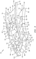
- FIG. 2 is a perspective illustration of the variable area vane arrangement 50 of FIG. 1 .
- FIG. 3 is a perspective illustration of a portion of the variable area vane arrangement 50 of FIG. 2 .
- the variable area vane arrangement 50 includes a plurality of vane arrangement segments 52.
- One or more of the vane arrangement segments 52 each includes a vane inner platform 54, a vane outer platform 56, and at least one multi-segment adjustable stator vane 58 (e.g., a hollow adjustable stator vane).
- One or more of the vane arrangement segments 52 each further includes at least one fixed stator vane 60 (e.g., a hollow fixed stator vane).
- the inner platform 54 extends axially relative to the axis 22 between an upstream platform end 62 and a downstream platform end 64. Referring to FIG. 3 , the inner platform 54 extends circumferentially relative to the axis 22 between a first platform end 66 and a second platform end 68. The inner platform 54 extends radially relative to the axis 22 between an inner platform surface 70 and an outer platform surface 72. The outer platform surface 72 forms a portion of an inner surface of the core gas path 46 (see FIG. 1 ).
- the outer platform 56 extends axially relative to the axis 22 between an upstream platform end 74 and a downstream platform end 76.
- the outer platform 56 extends circumferentially relative to the axis 22 between a first platform end 78 and a second platform end 80.
- the outer platform 56 extends radially relative to the axis 22 between an inner platform surface 82 and an outer platform surface 84.
- the inner platform surface 82 forms a portion of an outer surface of the core gas path 46 (see FIG. 1 ).
- the outer platform 56 includes one or more vane apertures such as, for example, a first vane aperture 86 and a second vane aperture 88.
- the first vane aperture 86 is located at (e.g., on, adjacent or proximate) the first platform end 78.
- the second vane aperture 88 is located at the second platform end 80.
- One or more of the vane apertures 86 and 88 each extends radially relative to the axis 22 through the outer platform 56 between the inner platform surface 82 and the outer platform surface 84.
- one or more of the vane apertures 86 and 88 each includes an aperture first portion 90, an aperture second portion 92, and an aperture shelf 94.
- the first portion 90 extends radially from the outer platform surface 84 to the second portion 92.
- the second portion 92 extends radially from the inner platform surface 82 to the first portion 90.
- the aperture shelf 94 is defined at the intersection between the first portion 90 and the second portion 92.
- the aperture shelf 94 may be configured as a substantially flat, parti-annular platform surface.
- the adjustable stator vane 58 is adapted to pivot about a variable vane axis 96, which may extend radially relative to the axis 22.
- the adjustable stator vane 58 includes a stator vane body 98, one or more shafts 100 and 102 (see also FIG. 8 ), and a flange 104.
- the stator vane body 98 extends axially relative to the axis 96 (e.g., radially relative to the axis 22) between a body inner end 106 and a body outer end 108.
- the stator vane body 98 includes an airfoil 110, a neck 112, one or more cavities 114, and one or more cooling apertures 116.
- the airfoil 110 extends axially relative to the axis 96 from the inner end 106 (see FIG. 3 ) to the neck 112.
- the airfoil 110 extends longitudinally between an airfoil leading edge 118 and an airfoil trailing edge 120.
- the airfoil 110 extends laterally between an airfoil concave surface 122 and an airfoil convex surface 124.
- the neck 112 extends axially relative to the axis 96 from the airfoil 110 to the outer end 108.
- the neck 112 extends longitudinally between a neck leading edge 126 (e.g., the airfoil leading edge 118) and a neck trailing edge 128.
- the neck 112 extends laterally between a neck first surface 130 (e.g., a portion of the airfoil concave surface 122) and a neck second surface (e.g., a portion of the airfoil convex surface 124).
- the neck 112 includes a body surface 132 that is located at the outer end 108.
- one or more of the cavities 114 each extends axially relative to the axis 96 into (or through) the stator vane body 98 from a respective cavity inlet 134 in the body surface 132.
- One or more of the cavities 114 for example, each extends axially from the respective cavity inlet 134, through the neck 112, and into the airfoil 110.
- one or more of the cooling apertures 116 each extends through the stator vane body 98 from a respective one of the cavities 114 to the airfoil leading edge 118.
- One or more of the cooling apertures 116 each extends through the stator vane body 98 from a respective one of the cavities 114 to the airfoil trailing edge 120.
- One or more of the cooling apertures 116 each extends through the stator vane body 98 from a respective one of the cavities 114 to the airfoil concave surface 122.
- One or more of the cooling apertures 116 each extends through the stator vane body 98 from a respective one of the cavities 114 to the airfoil convex surface 124.
- the inner shaft 100 (e.g., a solid shaft) is connected to the stator vane body 98 at the body inner end 106.
- the inner shaft 100 extends along the axis 96 from the body inner end 106.
- the inner shaft 100 is located a first distance from the airfoil leading edge 118.
- the inner shaft 100 is located a second distance from the airfoil trailing edge 120 that may be different (e.g., less) than the first distance.
- the outer shaft 102 (e.g., a solid shaft) is connected to the stator vane body 98 at the body outer end 108.
- the outer shaft 102 extends along the axis 96 from the body surface 132 to a distal shaft end 136.
- the outer shaft 102 is located a first distance from the airfoil leading edge 118.
- the outer shaft 102 is located a second distance from the airfoil trailing edge 120 that may be different (e.g., less) than the first distance.
- the flange 104 is connected to the stator vane body 98 at the body outer end 108.
- the flange 104 extends circumferentially around one or more of the cavity inlets 134 and/or the outer shaft 102.
- the flange 104 extends radially relative to the axis 96 out from the stator vane body 98.
- the flange 104 extends radially out from, for example, the neck leading edge 126, the neck trailing edge 128, the neck first surface 130 and/or the neck second surface (e.g., a portion of the airfoil convex surface 124) to a distal flange end 138.
- the flange 104 extends axially relative to the axis 96 between an inner flange surface 140 and an outer flange surface 142 (e.g., the body surface 132).
- the inner flange surface 140 is axially separated from a surface 144 of the airfoil 110 by a gap.
- the flange 104 includes a flange lip 146 and one or more cooling apertures 148.
- the flange lip 146 extends circumferentially substantially (or partially) around one or more of the inlets 134 and/or the outer shaft 102.
- the flange lip 146 for example, is located at and extends circumferentially along the distal flange end 138.
- the flange lip 146 extends axially relative to the axis 96 from the inner flange surface 140 towards the body inner end 106 (see FIG. 3 ) and to a vane surface 150.
- the vane surface 150 is axially separated from the airfoil surface 144 by a gap.
- one or more of the cooling apertures 148 extend axially through the flange 104 between the inner flange surface 140 and the outer flange surface 142.
- One or more of the cooling apertures 148 are located proximate the airfoil leading edge 118.
- One or more of the cooling apertures 148 are located proximate the airfoil concave surface 122.
- One or more of the cooling apertures 148 are located proximate the airfoil convex surface 124.
- the adjustable stator vane 58 is mated with the first vane aperture 86.
- the flange 104 is seated in the aperture first portion 90 and the vane surface 150 forms a seal with the aperture shelf 94.
- a cooling channel 152 extends circumferentially around the stator vane body 98 (e.g., the neck 112).
- the cooling channel 152 extends radially relative to the axis 96 between the stator vane body 98 (e.g., the neck 112) and the flange lip 146.
- the cooling channel 152 extends axially between the aperture shelf 94 and the inner flange surface 140.
- the inner platform 54 is arranged radially relative to the axis 22 within the outer platform 56.
- the airfoil 110 is arranged between and rotatably connected to the inner platform 54 and the outer platform 56.
- the outer shaft 102 is rotatably connected to the outer platform 56 with a bearing 154 such as, for example, a pillow block bearing or any other type of bearing or bushing.
- the inner shaft 100 is rotatably connected to the inner platform 54 with a bearing 156 such as, for example, a cartridge bearing or any other type of bearing or bushing.
- the fixed stator vane 60 includes an airfoil 158 that is arranged and extends between the inner platform 54 and the outer platform 56.
- the airfoil 158 is fixedly connected to (e.g., integral with) the inner platform 54 and/or the outer platform 56.
- each of the adjustable stator vanes 58 is mated with the second vane aperture 88.
- the flange 104 is seated in the aperture first portion 90 and the vane surface 150 engages the aperture shelf 94.
- the cooling channel 152 extends axially between the aperture shelf 94 and the inner flange surface 140.
- each of the vane arrangement segments 52 is mechanically fastened, welded, brazed, adhered and/or otherwise bonded between respective adjacent vane arrangement segments 52 (or to adjacent supporting static hardware) to form the variable area vane arrangement 50.
- each first platform end 66 is arranged adjacent to a respective second platform end 68 and each inner platform 54 is fastened to another inner platform 54, thereby forming an annular stator vane inner platform 162.
- Each first platform end 78 is arranged adjacent to a respective second platform end 80 and each outer platform 56 is fastened to another outer platform 56, thereby forming an annular stator vane outer platform 164.
- one or more of the adjustable stator vanes 58 are each pivoted about its axis 96 to guide the flow of core gas through the variable area vane arrangement 50 according to a trajectory.
- One or more of the adjustable stator vanes 58 may also or alternatively each be pivoted about its axis 96 to adjust (e.g., increase or decrease) the flow of core gas through the variable area vane arrangement 50.
- the vane surface 150 may respectively maintain the seal with the platform surfaces (e.g., the aperture shelves 94) during the pivoting of the respective adjustable stator vane 58.
- the flange 104 and the flange lip 146 therefore may reduce and/or eliminate gas leakage through the gap between the adjustable stator vane 58 and the annular stator vane outer platform 164 during the pivoting of the respective adjustable stator vane 58.
- the cavity inlets 134 respectively direct cooling air from a plenum 166 adjacent the outer platform surface 84 into the cavities 114.
- This cooling air may be a portion of the core air that is bled from the compressor section 29 (e.g., the HPC section 29B of FIG. 1 ) and directed into the plenum 166 through an internal passage (not shown).
- the cooling apertures 116 subsequently direct the cooling air out of the airfoil 110 to cool (e.g., film cool) the airfoil concave surface 122, the airfoil convex surface 124, the airfoil leading edge 118, and/or the airfoil trailing edge 120.
- one or more of the cooling apertures 148 may direct the cooling air from the plenum 166 into the cooling channel 152 to cool (e.g., impingement cool) the aperture shelve 94.
- the cooling air may subsequently leak through the gap to cool (e.g., film cool) the inner platform surface 82.
- the gap may become larger and a portion of the inner flange surface 140 and/or one or more of the cooling apertures 148 may become exposed to the core gas path 46.
- the cooling apertures 148 therefore may no longer provide impingement cooling to aperture shelf 94, but may rather provide film cooling for inner platform surface 82.
- one or more of the adjustable stator vanes 58 may each include a vane actuation element 168 connected to the respective flange 104.
- the actuation element 168 may be configured as a cylindrical shaft, and extend axially from the flange outer surface 142 to a distal actuation element end 170.
- the distal actuation element end 170 is adapted to connect to a vane actuator (not shown) such as, for example, a unison ring.
- the actuation element may be configured as a linkage arm connected to the distal end of the outer shaft.
- the present invention is not limited to any particular actuation element or vane actuator configurations.
- the outer platform 56 may include a platform lip 172 that extends substantially (or partially) along an edge of the first and/or the second vane apertures 86 and 88.
- the platform lip 172 extends axially relative to the axis 96 into the cooling channel 152 from the aperture shelf 94.
- the adjustable stator vane 58 is formed from a plurality of discrete vane segments, which include a first vane segment 174 and a second vane segment 176.
- the first vane segment 174 includes the outer shaft 102, the flange 104 and a first portion 178 of the neck 112.
- the second vane segment 176 includes the airfoil 110, the inner shaft 100 and a second portion 180 of the neck 112.
- the first and/or the second vane segments 174 and 176 are each cast, machined, milled, forged and/or otherwise formed as a discrete unitary body.
- the first portion 178 of the neck 112, for example, is formed integral with the outer shaft 102 and the flange 104.
- the airfoil 110 is formed integral with the inner shaft 100 and the second portion 180 of the neck 112.
- the first vane segment 174 and the second vane segment 176 therefore may be formed from different types of materials (e.g., different metals and/or metal alloys).
- the first vane segment 174 and the second vane segment 176 may alternatively be formed from the same type of material.
- a region 182 of the flange 104 that overlaps the airfoil surface 144 may be formed using standard formation techniques before the vane segments 174 and 176 are fastened together.
- the airfoil 110 may obstruct access to the region 182. This obstructed access may increase the difficultly and/or cost to form the inner flange surface 140 and/or the flange lip 146 in the region 182. The obstructed access may also or alternatively limit the complexity of the flange 104 design in the region 182.
- the first vane segment 174 engages (e.g., contacts) the second vane segment 176 at a joint 184.
- the joint 184 may be configured as a lap joint as illustrated in FIG. 11 .
- the joint 184 may be configured as a scarf joint as illustrated in FIG. 12 .
- the joint 184 may be configured as a butt joint as illustrated in FIG. 13 or any other type of joint.
- the first vane segment 174 is fastened to the second vane segment 176 at the joint 184.
- the first vane segment 174 for example, is welded, brazed, adhered and/or otherwise bonded to the second vane segment 176 at the joint 184.
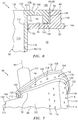
- FIG. 12 is a side sectional illustration of a portion of the adjustable stator vane 58 with alternate embodiment vane segments 188 and 190.
- the first vane segment 188 includes the outer shaft 102 (not shown), the flange 104, the neck 112 and a first portion 192 of the airfoil 110.
- the second vane segment 190 includes a second portion 194 of the airfoil 110 and the inner shaft 100 (not shown).
- FIG. 13 is a side sectional illustration of a portion of the adjustable stator vane 58 with alternate embodiment vane segments 196 and 198.
- the first vane segment 196 includes the outer shaft 102 (not shown), the flange 104 and the neck 112.
- the second vane segment 198 includes at least a portion of the airfoil 110.
- the second vane segment 198 may also include the inner shaft 100 (not shown).
- An inner sleeve 186 may be welded, brazed, adhered and/or otherwise bonded to the first and/or the second vane segments 196 and 198 at the joint 184 to reinforce the connection between the vane segments 196 and 198.
- the first vane segment 196 may be indirectly fastened to the second vane segment 198 at the joint 184 through the inner sleeve 186, or another intermediate vane segment (not shown).
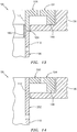
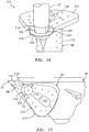
- FIG. 14 is a side sectional illustration of a portion of the adjustable stator vane 58 with alternate embodiment vane segments 200 and 202.
- the first vane segment 200 includes the flange 104.
- the second vane segment 202 includes the airfoil 110, the neck 112, the inner shaft 100 (not shown) and the outer shaft 102 (not shown).
- FIG. 15 is a side sectional illustration of a portion of the adjustable stator vane 58 with alternate embodiment vane segments 204 and 206.
- the first vane segment 204 includes the flange 104 and the neck 112.
- the second vane segment 206 includes the airfoil 110 and the inner shaft 100 (not shown).
- the first vane segment 204 engages the second vane segment 206 at the joint 184.
- the first vane segment 204 is mechanically fastened to the second vane segment 206 with at least one fastener.
- the outer shaft 102 for example, includes a threaded portion 208 that mates with (e.g., threads into) the second vane segment 206.
- a shoulder 210 of the outer shaft 102 clamps the first vane segment 204 against the second vane segment 206.
- the first vane segment 204 may also or alternatively be mechanically fastened to the second vane segment 206 with one or more fasteners that are discrete from the outer shaft 102.
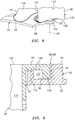
- FIG. 16 is a perspective illustration of another multi-segment adjustable stator vane 212.
- the adjustable stator vane 212 includes an alternate embodiment flange 214 and a seal 216 (e.g., a rotatable feather seal).
- the flange 214 extends circumferentially, partially around one or more of the cavity inlets 134 and/or the outer shaft 102, between a flange first end 218 and a flange second end 220.
- the first end 218 and the second end 220 are arranged adjacent to and on opposing sides of the outer shaft 102.
- the seal 216 extends circumferentially, partially around the outer shaft 102, between a seal first end 222 and a seal second end 224.
- the seal first end 222 is engaged with (e.g., contacts) and forms a seal with the flange first end 218.
- the seal second end 224 is engaged with and forms a seal with the flange second end 220.
- the seal 216 is mated with the outer platform 56'.
- a parti-annular body 226 of the seal 216 for example, is inserted into a slot 228 in the outer platform 56', which seals the gap between the outer shaft 102 and the outer platform 56'.
- FIG. 18 is a perspective cutaway illustration of a portion of another variable area vane arrangement 230.
- the variable area vane arrangement 230 includes an outer platform 231 with one or more vane apertures 232.
- each vane aperture 232 includes an aperture first portion 234, an aperture second portion 236 and an aperture third portion 238.
- the second portion 236 defines a slot, between the first and third portions 234 and 238, that receives a flange 240 of another multi-segment adjustable stator vane 239.
- An outer shaft 242 is connected to an airfoil 244 at (e.g., proximate) a body outer end 246.
- the flange 240 extends circumferentially around a cavity inlet 248, but not the outer shaft 242.
- the shape, size, number and/or location of one or more of the cavities, cavity inlets, cooling apertures and vane apertures may vary depending upon the size and/or design of the variable area vane arrangement.
- some or all of the cavities within a respective airfoil may be interconnected; e.g., fluidly coupled.
- the cavities within a respective airfoil may be fluidly separate.
- One or more of the cavity inlets and/or the cooling apertures may have elongated (e.g., rectangular, oval, elliptical, etc.) cross-sectional geometries.
- One or more of the cavity inlets and/or the cooling apertures may alternatively have circular cross-sectional geometries.
- One or more of the cavity inlets and/or the cooling apertures may have flared geometries.
- the second vane apertures may be omitted, and the first vane aperture may be located between the first and the second platform ends.
- the present invention therefore is not limited to any particular cavity and/or cavity inlet or cooling aperture quantities or configurations.
- the adjustable stator vane may include more than two vane segments.
- upstream is used to orient the components of the variable area vane arrangements described above relative to the turbine engine 20 and its axis 22.
- a person of skill in the art will recognize, however, one or more of these components may be utilized in orientations other than those described above.
- the flange may be connected to the stator vane body at the body inner end, and the inner platform may include the vane apertures.
- the present invention therefore is not limited to any particular variable area vane arrangement spatial orientations.
- variable area vane arrangements described above may be utilized to direct the flow of air through an engine section other than the LPT section 31B as described above.
- the variable area vane arrangement 50 may direct the flow of core air into rotor stages of the HPT section 31A, or between the HPT section 31A and the LPT section 31B.
- the variable area vane arrangement 50 may direct the flow of air into or between adjacent rotor stages of one of the engine sections 28, 29A and 29B, or any other section of the engine 20.
- variable area vane arrangement may be included in various turbine engines other than the one described above.
- the variable area vane arrangement may be included in a geared turbine engine where a gear train connects one or more shafts to one or more rotors in a fan section, a compressor section and/or any other engine section.
- the variable area vane arrangement may be included in a turbine engine configured without a gear train.
- the variable area vane arrangement may be included in a geared or non-geared turbine engine configured with a single spool, with two spools (e.g., see FIG. 1 ), or with more than two spools.
- variable area vane arrangement may be included in a turbine engine with a single flow path (e.g., stream), with two flow paths (e.g., see FIG. 1 ), or more that two flow paths.
- the turbine engine may be configured as a turbofan engine, a turbojet engine, a propfan engine, or any other type of turbine engine. The present invention therefore is not limited to any particular types or configurations of turbine engines.
Landscapes
- Engineering & Computer Science (AREA)
- Mechanical Engineering (AREA)
- General Engineering & Computer Science (AREA)
- Chemical & Material Sciences (AREA)
- Combustion & Propulsion (AREA)
- Physics & Mathematics (AREA)
- Fluid Mechanics (AREA)
- Turbine Rotor Nozzle Sealing (AREA)
- Structures Of Non-Positive Displacement Pumps (AREA)
Claims (13)
- Ensemble pour un moteur à turbine, comprenant :une pluralité de segments d'aube (52) fixés ensemble pour former une aube de stator réglable (58) qui pivote autour d'un axe d'aube variable (96) et comporteun corps d'aube de stator (98) s'étendant axialement entre une première extrémité (108) et une seconde extrémité (106), et comportant un profil aérodynamique (110), une surface de corps (132) et une cavité (114), dans lequel la surface de corps (132) est située au niveau de la première extrémité (108), et la cavité (114) s'étend axialement depuis une entrée (134) dans la surface de corps (132) et dans le profil aérodynamique (110) ;un arbre (102) s'étendant le long de l'axe d'aube variable (96) depuis la première extrémité (108) ; etune bride (104 ; 214) s'étendant circonférentiellement au moins partiellement autour de l'entrée (134), et radialement depuis le corps d'aube de stator (98) ;dans lequel un premier des segments d'aube (52) comporte la bride (104, 214), et un second des segments d'aube comporte au moins une partie du profil aérodynamique (110) ;caractérisé en ce que :le corps d'aube de stator (98) comporte en outre un col (112) qui s'étend axialement entre la surface de corps (132) et le profil aérodynamique (110) ;la bride (104) s'étend circonférentiellement autour et radialement depuis le col (112) ; etla bride (104) est séparée axialement d'une surface (144) du profil aérodynamique (110) par un espace.
- Ensemble selon la revendication 1, dans lequel la bride (104) s'étend circonférentiellement autour de l'entrée (134).
- Ensemble selon la revendication 2, dans lequel la bride (104) s'étend circonférentiellement autour de l'arbre (102).
- Ensemble selon la revendication 1, 2 ou 3, comprenant en outre :un joint (216) s'étendant circonférentiellement partiellement autour de l'arbre (102) entre une première extrémité de joint (222) et une seconde extrémité de joint (224) ;dans lequel la bride (214) s'étend circonférentiellement partiellement autour de l'entrée (134) et de l'arbre (102) entre une première extrémité de bride (218) et une seconde extrémité de bride (220) ; etdans lequel la première extrémité de joint (222) vient en prise avec la première extrémité de bride (218), et la seconde extrémité de joint (224) vient en prise avec la seconde extrémité de bride (220).
- Ensemble selon une quelconque revendication précédente, dans lequel le premier des segments d'aube (52) comporte en outre une partie du profil aérodynamique (110).
- Ensemble selon une quelconque revendication précédente, dans lequel :le premier des segments d'aube (52) comporte en outre le col (121) ; oule premier des segments d'aube (52) comporte en outre une première partie (178) du col (112), et le second des segments d'aube comporte en outre une seconde partie (180) du col (112).
- Ensemble selon une quelconque revendication précédente, comprenant en outre :une lèvre (146) s'étendant circonférentiellement au moins partiellement autour de l'entrée (134) et de l'arbre (102), et axialement depuis une surface de la bride (104) vers la seconde extrémité (106) ;dans lequel un canal (152) s'étend radialement entre le corps d'aube de stator (98) et la lèvre (146) ;dans lequel une ouverture de refroidissement (148) s'étend axialement à travers la bride (104) vers le canal (152).
- Ensemble selon une quelconque revendication précédente, dans lequel
le profil aérodynamique (110) s'étend longitudinalement entre un bord d'attaque (118) et un bord de fuite (120) ;
le profil aérodynamique (110) s'étend latéralement entre une surface concave (122) et une surface convexe (124) ; et
le profil aérodynamique (110) comporte une ouverture de refroidissement (118) qui s'étend depuis la cavité (114) à l'un parmi le bord d'attaque (118), le bord de fuite (120), la surface concave (122) et la surface convexe (124). - Ensemble selon une quelconque revendication précédente, dans lequel le premier des segments d'aube (52) vient en prise avec le second des segments d'aube (52) au niveau d'un joint bout à bout, d'un joint à recouvrement ou d'un joint en biseau (184) .
- Ensemble selon une quelconque revendication précédente, dans lequel le premier des segments d'aube (52) est au moins l'un parmi des segments soudés, brasés et collés au second des segments d'aube (52).
- Ensemble selon une quelconque revendication précédente, dans lequel le premier des segments d'aube (52) est fixé mécaniquement au second des segments d'aube (52) avec une fixation.
- Ensemble selon une quelconque revendication précédente, comprenant en outre :une première plateforme d'aube (56) comportant une ouverture d'aube (86, 88) ; etune seconde plateforme d'aube (54) ;dans lequel l'arbre (102) comprend un premier arbre qui est relié de manière rotative à la première plateforme (56) ;dans lequel l'aube de stator réglable (58) comporte en outre un second arbre qui s'étend le long de l'axe d'aube variable (96) depuis la seconde extrémité (106), et est relié de manière rotative à la seconde plateforme (54) ; etdans lequel l'aube de stator réglable (58) s'étend axialement depuis la seconde extrémité (106) au moins partiellement dans l'ouverture d'aube (86, 88) et à la première extrémité (104), et le profil aérodynamique (110) est disposé entre une première plateforme (56) et la seconde plateforme (54) .
- Ensemble selon la revendication 12, comprenant en outre :une aube de stator fixe (60) reliée à la première plateforme (56) et à la seconde plateforme (54) ;dans lequel la seconde plateforme (54) est disposée à l'intérieur de la première plateforme (56).
Applications Claiming Priority (1)
| Application Number | Priority Date | Filing Date | Title |
|---|---|---|---|
| PCT/US2013/023440 WO2014116259A1 (fr) | 2013-01-28 | 2013-01-28 | Aube de stator réglable à segment multiple pour un ensemble d'aube à section variable |
Publications (3)
| Publication Number | Publication Date |
|---|---|
| EP2948642A1 EP2948642A1 (fr) | 2015-12-02 |
| EP2948642A4 EP2948642A4 (fr) | 2016-05-25 |
| EP2948642B1 true EP2948642B1 (fr) | 2020-10-21 |
Family
ID=51227925
Family Applications (1)
| Application Number | Title | Priority Date | Filing Date |
|---|---|---|---|
| EP13872458.8A Active EP2948642B1 (fr) | 2013-01-28 | 2013-01-28 | Aube de stator réglable à segment multiple pour un ensemble d'aube à section variable |
Country Status (3)
| Country | Link |
|---|---|
| US (1) | US10047629B2 (fr) |
| EP (1) | EP2948642B1 (fr) |
| WO (1) | WO2014116259A1 (fr) |
Families Citing this family (10)
| Publication number | Priority date | Publication date | Assignee | Title |
|---|---|---|---|---|
| US9759078B2 (en) | 2015-01-27 | 2017-09-12 | United Technologies Corporation | Airfoil module |
| US10280762B2 (en) * | 2015-11-19 | 2019-05-07 | United Technologies Corporation | Multi-chamber platform cooling structures |
| US10711640B2 (en) * | 2017-04-11 | 2020-07-14 | Raytheon Technologies Corporation | Cooled cooling air to blade outer air seal passing through a static vane |
| JP6811141B2 (ja) * | 2017-04-17 | 2021-01-13 | 三菱パワー株式会社 | タービン静翼列 |
| US11092167B2 (en) * | 2018-08-28 | 2021-08-17 | Pratt & Whitney Canada Corp. | Variable vane actuating system |
| US11092032B2 (en) * | 2018-08-28 | 2021-08-17 | Pratt & Whitney Canada Corp. | Variable vane actuating system |
| US11428243B2 (en) | 2019-09-09 | 2022-08-30 | Raytheon Technologies Corporation | Variable vane arrangement with vane receptacle insert(s) |
| PL431184A1 (pl) * | 2019-09-17 | 2021-03-22 | General Electric Company Polska Spółka Z Ograniczoną Odpowiedzialnością | Zespół silnika turbinowego |
| US20230107877A1 (en) * | 2020-02-26 | 2023-04-06 | Siemens Energy Global GmbH & Co. KG | Gas turbine engine stationary vane with contoured platform |
| US20210332756A1 (en) * | 2020-04-24 | 2021-10-28 | General Electric Company | Methods and apparatus for gas turbine frame flow path hardware cooling |
Family Cites Families (18)
| Publication number | Priority date | Publication date | Assignee | Title |
|---|---|---|---|---|
| US3558237A (en) | 1969-06-25 | 1971-01-26 | Gen Motors Corp | Variable turbine nozzles |
| US4498291A (en) | 1982-10-06 | 1985-02-12 | Rolls-Royce Limited | Turbine overspeed limiter for turbomachines |
| US4883404A (en) * | 1988-03-11 | 1989-11-28 | Sherman Alden O | Gas turbine vanes and methods for making same |
| US5931636A (en) | 1997-08-28 | 1999-08-03 | General Electric Company | Variable area turbine nozzle |
| US6193465B1 (en) * | 1998-09-28 | 2001-02-27 | General Electric Company | Trapped insert turbine airfoil |
| US20030106215A1 (en) | 2001-12-11 | 2003-06-12 | General Electric Company | Turbine nozzle segment and method of repairing same |
| FR2858027B1 (fr) * | 2003-07-21 | 2005-09-23 | Snecma Moteurs | Compresseur haute pression a cycle hybride et turbomachine comprenant un tel compresseur |
| US6997676B2 (en) | 2004-03-10 | 2006-02-14 | General Electric Company | Bifurcated outlet guide vanes |
| FR2902822B1 (fr) | 2006-06-21 | 2008-08-22 | Snecma Sa | Palier pour aube de stator a calage variable |
| US8007229B2 (en) | 2007-05-24 | 2011-08-30 | United Technologies Corporation | Variable area turbine vane arrangement |
| US8202043B2 (en) | 2007-10-15 | 2012-06-19 | United Technologies Corp. | Gas turbine engines and related systems involving variable vanes |
| US8262345B2 (en) * | 2009-02-06 | 2012-09-11 | General Electric Company | Ceramic matrix composite turbine engine |
| DK2317124T3 (en) * | 2009-10-01 | 2018-10-08 | Vestas Wind Sys As | Wind turbine blade |
| EP2494155A1 (fr) * | 2009-10-27 | 2012-09-05 | Volvo Aero Corporation | Composant de moteur de turbine à gaz |
| US9279335B2 (en) * | 2011-08-03 | 2016-03-08 | United Technologies Corporation | Vane assembly for a gas turbine engine |
| US9273565B2 (en) * | 2012-02-22 | 2016-03-01 | United Technologies Corporation | Vane assembly for a gas turbine engine |
| US9103222B2 (en) * | 2012-06-22 | 2015-08-11 | United Technologies Corporation | Turbine engine variable area vane with feather seal |
| US9500122B2 (en) * | 2013-06-28 | 2016-11-22 | General Electric Company | Variable geometry nozzle and associated method of operation |
-
2013
- 2013-01-28 WO PCT/US2013/023440 patent/WO2014116259A1/fr active Application Filing
- 2013-01-28 US US14/763,719 patent/US10047629B2/en active Active
- 2013-01-28 EP EP13872458.8A patent/EP2948642B1/fr active Active
Non-Patent Citations (1)
| Title |
|---|
| None * |
Also Published As
| Publication number | Publication date |
|---|---|
| WO2014116259A1 (fr) | 2014-07-31 |
| EP2948642A1 (fr) | 2015-12-02 |
| EP2948642A4 (fr) | 2016-05-25 |
| US20150369079A1 (en) | 2015-12-24 |
| US10047629B2 (en) | 2018-08-14 |
Similar Documents
| Publication | Publication Date | Title |
|---|---|---|
| EP2948642B1 (fr) | Aube de stator réglable à segment multiple pour un ensemble d'aube à section variable | |
| US20180328187A1 (en) | Turbine engine with an airfoil and insert | |
| US10808546B2 (en) | Gas turbine engine airfoil trailing edge suction side cooling | |
| US11143039B2 (en) | Turbine engine component including an axially aligned skin core passage interrupted by a pedestal | |
| EP3543464B1 (fr) | Déflecteur à double cavité | |
| EP2905425B1 (fr) | Système d'étanchéité et aube variable | |
| US20160032727A1 (en) | Rotor blade with a conic spline fillet at an intersection between a platform and a neck | |
| US10465542B2 (en) | Gas turbine engine turbine vane baffle and serpentine cooling passage | |
| US10151210B2 (en) | Endwall contouring for airfoil rows with varying airfoil geometries | |
| US9938840B2 (en) | Stator vane with platform having sloped face | |
| US10837291B2 (en) | Turbine engine with component having a cooled tip | |
| US10001023B2 (en) | Grooved seal arrangement for turbine engine | |
| US20180051571A1 (en) | Airfoil for a turbine engine with porous rib | |
| US11629602B2 (en) | Cooling schemes for airfoils for gas turbine engines | |
| EP2946081B1 (fr) | Agencement d'aube à surface variable pour un moteur de turbine | |
| US20180038236A1 (en) | Gas turbine engine stator vane baffle arrangement | |
| EP3045666B1 (fr) | Plateforme de surface portante avec orifices d'alimentation de refroidissement | |
| EP3508693B1 (fr) | Passages d'air de refroidissement séparés pour aube de turbine | |
| US10047617B2 (en) | Gas turbine engine airfoil platform edge geometry | |
| US11725531B2 (en) | Bore compartment seals for gas turbine engines | |
| US20160230559A1 (en) | Rotor with axial arm having protruding ramp |
Legal Events
| Date | Code | Title | Description |
|---|---|---|---|
| PUAI | Public reference made under article 153(3) epc to a published international application that has entered the european phase |
Free format text: ORIGINAL CODE: 0009012 |
|
| 17P | Request for examination filed |
Effective date: 20150728 |
|
| AK | Designated contracting states |
Kind code of ref document: A1 Designated state(s): AL AT BE BG CH CY CZ DE DK EE ES FI FR GB GR HR HU IE IS IT LI LT LU LV MC MK MT NL NO PL PT RO RS SE SI SK SM TR |
|
| AX | Request for extension of the european patent |
Extension state: BA ME |
|
| DAX | Request for extension of the european patent (deleted) | ||
| A4 | Supplementary search report drawn up and despatched |
Effective date: 20160428 |
|
| RIC1 | Information provided on ipc code assigned before grant |
Ipc: F01D 5/14 20060101ALN20160421BHEP Ipc: F01D 9/06 20060101ALN20160421BHEP Ipc: F01D 17/16 20060101AFI20160421BHEP Ipc: F02C 9/22 20060101ALI20160421BHEP Ipc: F01D 9/04 20060101ALI20160421BHEP |
|
| RAP1 | Party data changed (applicant data changed or rights of an application transferred) |
Owner name: UNITED TECHNOLOGIES CORPORATION |
|
| STAA | Information on the status of an ep patent application or granted ep patent |
Free format text: STATUS: EXAMINATION IS IN PROGRESS |
|
| 17Q | First examination report despatched |
Effective date: 20190506 |
|
| RIC1 | Information provided on ipc code assigned before grant |
Ipc: F01D 9/04 20060101ALI20191119BHEP Ipc: F01D 5/14 20060101ALN20191119BHEP Ipc: F01D 9/06 20060101ALN20191119BHEP Ipc: F01D 17/16 20060101AFI20191119BHEP Ipc: F02C 9/22 20060101ALI20191119BHEP |
|
| GRAP | Despatch of communication of intention to grant a patent |
Free format text: ORIGINAL CODE: EPIDOSNIGR1 |
|
| STAA | Information on the status of an ep patent application or granted ep patent |
Free format text: STATUS: GRANT OF PATENT IS INTENDED |
|
| INTG | Intention to grant announced |
Effective date: 20200102 |
|
| GRAJ | Information related to disapproval of communication of intention to grant by the applicant or resumption of examination proceedings by the epo deleted |
Free format text: ORIGINAL CODE: EPIDOSDIGR1 |
|
| STAA | Information on the status of an ep patent application or granted ep patent |
Free format text: STATUS: EXAMINATION IS IN PROGRESS |
|
| GRAP | Despatch of communication of intention to grant a patent |
Free format text: ORIGINAL CODE: EPIDOSNIGR1 |
|
| STAA | Information on the status of an ep patent application or granted ep patent |
Free format text: STATUS: GRANT OF PATENT IS INTENDED |
|
| INTC | Intention to grant announced (deleted) | ||
| RIC1 | Information provided on ipc code assigned before grant |
Ipc: F01D 17/16 20060101AFI20200422BHEP Ipc: F01D 9/04 20060101ALI20200422BHEP Ipc: F01D 5/14 20060101ALN20200422BHEP Ipc: F02C 9/22 20060101ALI20200422BHEP Ipc: F01D 9/06 20060101ALN20200422BHEP |
|
| INTG | Intention to grant announced |
Effective date: 20200514 |
|
| GRAS | Grant fee paid |
Free format text: ORIGINAL CODE: EPIDOSNIGR3 |
|
| GRAA | (expected) grant |
Free format text: ORIGINAL CODE: 0009210 |
|
| STAA | Information on the status of an ep patent application or granted ep patent |
Free format text: STATUS: THE PATENT HAS BEEN GRANTED |
|
| AK | Designated contracting states |
Kind code of ref document: B1 Designated state(s): AL AT BE BG CH CY CZ DE DK EE ES FI FR GB GR HR HU IE IS IT LI LT LU LV MC MK MT NL NO PL PT RO RS SE SI SK SM TR |
|
| REG | Reference to a national code |
Ref country code: GB Ref legal event code: FG4D |
|
| REG | Reference to a national code |
Ref country code: CH Ref legal event code: EP |
|
| REG | Reference to a national code |
Ref country code: IE Ref legal event code: FG4D |
|
| REG | Reference to a national code |
Ref country code: DE Ref legal event code: R096 Ref document number: 602013073530 Country of ref document: DE |
|
| REG | Reference to a national code |
Ref country code: AT Ref legal event code: REF Ref document number: 1326051 Country of ref document: AT Kind code of ref document: T Effective date: 20201115 |
|
| REG | Reference to a national code |
Ref country code: AT Ref legal event code: MK05 Ref document number: 1326051 Country of ref document: AT Kind code of ref document: T Effective date: 20201021 |
|
| RAP2 | Party data changed (patent owner data changed or rights of a patent transferred) |
Owner name: RAYTHEON TECHNOLOGIES CORPORATION |
|
| REG | Reference to a national code |
Ref country code: NL Ref legal event code: MP Effective date: 20201021 |
|
| PG25 | Lapsed in a contracting state [announced via postgrant information from national office to epo] |
Ref country code: GR Free format text: LAPSE BECAUSE OF FAILURE TO SUBMIT A TRANSLATION OF THE DESCRIPTION OR TO PAY THE FEE WITHIN THE PRESCRIBED TIME-LIMIT Effective date: 20210122 Ref country code: FI Free format text: LAPSE BECAUSE OF FAILURE TO SUBMIT A TRANSLATION OF THE DESCRIPTION OR TO PAY THE FEE WITHIN THE PRESCRIBED TIME-LIMIT Effective date: 20201021 Ref country code: RS Free format text: LAPSE BECAUSE OF FAILURE TO SUBMIT A TRANSLATION OF THE DESCRIPTION OR TO PAY THE FEE WITHIN THE PRESCRIBED TIME-LIMIT Effective date: 20201021 Ref country code: NL Free format text: LAPSE BECAUSE OF FAILURE TO SUBMIT A TRANSLATION OF THE DESCRIPTION OR TO PAY THE FEE WITHIN THE PRESCRIBED TIME-LIMIT Effective date: 20201021 Ref country code: NO Free format text: LAPSE BECAUSE OF FAILURE TO SUBMIT A TRANSLATION OF THE DESCRIPTION OR TO PAY THE FEE WITHIN THE PRESCRIBED TIME-LIMIT Effective date: 20210121 Ref country code: PT Free format text: LAPSE BECAUSE OF FAILURE TO SUBMIT A TRANSLATION OF THE DESCRIPTION OR TO PAY THE FEE WITHIN THE PRESCRIBED TIME-LIMIT Effective date: 20210222 |
|
| REG | Reference to a national code |
Ref country code: LT Ref legal event code: MG4D |
|
| PG25 | Lapsed in a contracting state [announced via postgrant information from national office to epo] |
Ref country code: ES Free format text: LAPSE BECAUSE OF FAILURE TO SUBMIT A TRANSLATION OF THE DESCRIPTION OR TO PAY THE FEE WITHIN THE PRESCRIBED TIME-LIMIT Effective date: 20201021 Ref country code: AT Free format text: LAPSE BECAUSE OF FAILURE TO SUBMIT A TRANSLATION OF THE DESCRIPTION OR TO PAY THE FEE WITHIN THE PRESCRIBED TIME-LIMIT Effective date: 20201021 Ref country code: BG Free format text: LAPSE BECAUSE OF FAILURE TO SUBMIT A TRANSLATION OF THE DESCRIPTION OR TO PAY THE FEE WITHIN THE PRESCRIBED TIME-LIMIT Effective date: 20210121 Ref country code: IS Free format text: LAPSE BECAUSE OF FAILURE TO SUBMIT A TRANSLATION OF THE DESCRIPTION OR TO PAY THE FEE WITHIN THE PRESCRIBED TIME-LIMIT Effective date: 20210221 Ref country code: PL Free format text: LAPSE BECAUSE OF FAILURE TO SUBMIT A TRANSLATION OF THE DESCRIPTION OR TO PAY THE FEE WITHIN THE PRESCRIBED TIME-LIMIT Effective date: 20201021 Ref country code: LV Free format text: LAPSE BECAUSE OF FAILURE TO SUBMIT A TRANSLATION OF THE DESCRIPTION OR TO PAY THE FEE WITHIN THE PRESCRIBED TIME-LIMIT Effective date: 20201021 Ref country code: SE Free format text: LAPSE BECAUSE OF FAILURE TO SUBMIT A TRANSLATION OF THE DESCRIPTION OR TO PAY THE FEE WITHIN THE PRESCRIBED TIME-LIMIT Effective date: 20201021 |
|
| PG25 | Lapsed in a contracting state [announced via postgrant information from national office to epo] |
Ref country code: HR Free format text: LAPSE BECAUSE OF FAILURE TO SUBMIT A TRANSLATION OF THE DESCRIPTION OR TO PAY THE FEE WITHIN THE PRESCRIBED TIME-LIMIT Effective date: 20201021 |
|
| REG | Reference to a national code |
Ref country code: DE Ref legal event code: R097 Ref document number: 602013073530 Country of ref document: DE |
|
| PG25 | Lapsed in a contracting state [announced via postgrant information from national office to epo] |
Ref country code: RO Free format text: LAPSE BECAUSE OF FAILURE TO SUBMIT A TRANSLATION OF THE DESCRIPTION OR TO PAY THE FEE WITHIN THE PRESCRIBED TIME-LIMIT Effective date: 20201021 Ref country code: SK Free format text: LAPSE BECAUSE OF FAILURE TO SUBMIT A TRANSLATION OF THE DESCRIPTION OR TO PAY THE FEE WITHIN THE PRESCRIBED TIME-LIMIT Effective date: 20201021 Ref country code: LT Free format text: LAPSE BECAUSE OF FAILURE TO SUBMIT A TRANSLATION OF THE DESCRIPTION OR TO PAY THE FEE WITHIN THE PRESCRIBED TIME-LIMIT Effective date: 20201021 Ref country code: SM Free format text: LAPSE BECAUSE OF FAILURE TO SUBMIT A TRANSLATION OF THE DESCRIPTION OR TO PAY THE FEE WITHIN THE PRESCRIBED TIME-LIMIT Effective date: 20201021 Ref country code: EE Free format text: LAPSE BECAUSE OF FAILURE TO SUBMIT A TRANSLATION OF THE DESCRIPTION OR TO PAY THE FEE WITHIN THE PRESCRIBED TIME-LIMIT Effective date: 20201021 Ref country code: CZ Free format text: LAPSE BECAUSE OF FAILURE TO SUBMIT A TRANSLATION OF THE DESCRIPTION OR TO PAY THE FEE WITHIN THE PRESCRIBED TIME-LIMIT Effective date: 20201021 |
|
| PLBE | No opposition filed within time limit |
Free format text: ORIGINAL CODE: 0009261 |
|
| STAA | Information on the status of an ep patent application or granted ep patent |
Free format text: STATUS: NO OPPOSITION FILED WITHIN TIME LIMIT |
|
| PG25 | Lapsed in a contracting state [announced via postgrant information from national office to epo] |
Ref country code: DK Free format text: LAPSE BECAUSE OF FAILURE TO SUBMIT A TRANSLATION OF THE DESCRIPTION OR TO PAY THE FEE WITHIN THE PRESCRIBED TIME-LIMIT Effective date: 20201021 Ref country code: MC Free format text: LAPSE BECAUSE OF FAILURE TO SUBMIT A TRANSLATION OF THE DESCRIPTION OR TO PAY THE FEE WITHIN THE PRESCRIBED TIME-LIMIT Effective date: 20201021 |
|
| REG | Reference to a national code |
Ref country code: CH Ref legal event code: PL |
|
| 26N | No opposition filed |
Effective date: 20210722 |
|
| PG25 | Lapsed in a contracting state [announced via postgrant information from national office to epo] |
Ref country code: LU Free format text: LAPSE BECAUSE OF NON-PAYMENT OF DUE FEES Effective date: 20210128 |
|
| REG | Reference to a national code |
Ref country code: BE Ref legal event code: MM Effective date: 20210131 |
|
| PG25 | Lapsed in a contracting state [announced via postgrant information from national office to epo] |
Ref country code: IT Free format text: LAPSE BECAUSE OF FAILURE TO SUBMIT A TRANSLATION OF THE DESCRIPTION OR TO PAY THE FEE WITHIN THE PRESCRIBED TIME-LIMIT Effective date: 20201021 Ref country code: AL Free format text: LAPSE BECAUSE OF FAILURE TO SUBMIT A TRANSLATION OF THE DESCRIPTION OR TO PAY THE FEE WITHIN THE PRESCRIBED TIME-LIMIT Effective date: 20201021 |
|
| PG25 | Lapsed in a contracting state [announced via postgrant information from national office to epo] |
Ref country code: SI Free format text: LAPSE BECAUSE OF FAILURE TO SUBMIT A TRANSLATION OF THE DESCRIPTION OR TO PAY THE FEE WITHIN THE PRESCRIBED TIME-LIMIT Effective date: 20201021 Ref country code: CH Free format text: LAPSE BECAUSE OF NON-PAYMENT OF DUE FEES Effective date: 20210131 Ref country code: LI Free format text: LAPSE BECAUSE OF NON-PAYMENT OF DUE FEES Effective date: 20210131 |
|
| PG25 | Lapsed in a contracting state [announced via postgrant information from national office to epo] |
Ref country code: IE Free format text: LAPSE BECAUSE OF NON-PAYMENT OF DUE FEES Effective date: 20210128 |
|
| PG25 | Lapsed in a contracting state [announced via postgrant information from national office to epo] |
Ref country code: IS Free format text: LAPSE BECAUSE OF FAILURE TO SUBMIT A TRANSLATION OF THE DESCRIPTION OR TO PAY THE FEE WITHIN THE PRESCRIBED TIME-LIMIT Effective date: 20210221 |
|
| PG25 | Lapsed in a contracting state [announced via postgrant information from national office to epo] |
Ref country code: BE Free format text: LAPSE BECAUSE OF NON-PAYMENT OF DUE FEES Effective date: 20210131 |
|
| PG25 | Lapsed in a contracting state [announced via postgrant information from national office to epo] |
Ref country code: HU Free format text: LAPSE BECAUSE OF FAILURE TO SUBMIT A TRANSLATION OF THE DESCRIPTION OR TO PAY THE FEE WITHIN THE PRESCRIBED TIME-LIMIT; INVALID AB INITIO Effective date: 20130128 |
|
| P01 | Opt-out of the competence of the unified patent court (upc) registered |
Effective date: 20230520 |
|
| PG25 | Lapsed in a contracting state [announced via postgrant information from national office to epo] |
Ref country code: CY Free format text: LAPSE BECAUSE OF FAILURE TO SUBMIT A TRANSLATION OF THE DESCRIPTION OR TO PAY THE FEE WITHIN THE PRESCRIBED TIME-LIMIT Effective date: 20201021 |
|
| PGFP | Annual fee paid to national office [announced via postgrant information from national office to epo] |
Ref country code: GB Payment date: 20231219 Year of fee payment: 12 |
|
| PGFP | Annual fee paid to national office [announced via postgrant information from national office to epo] |
Ref country code: FR Payment date: 20231219 Year of fee payment: 12 |
|
| PG25 | Lapsed in a contracting state [announced via postgrant information from national office to epo] |
Ref country code: MK Free format text: LAPSE BECAUSE OF FAILURE TO SUBMIT A TRANSLATION OF THE DESCRIPTION OR TO PAY THE FEE WITHIN THE PRESCRIBED TIME-LIMIT Effective date: 20201021 |
|
| PGFP | Annual fee paid to national office [announced via postgrant information from national office to epo] |
Ref country code: DE Payment date: 20231219 Year of fee payment: 12 |