EP2948362B1 - Support structure and method of producing a support structure - Google Patents
Support structure and method of producing a support structure Download PDFInfo
- Publication number
- EP2948362B1 EP2948362B1 EP13792667.1A EP13792667A EP2948362B1 EP 2948362 B1 EP2948362 B1 EP 2948362B1 EP 13792667 A EP13792667 A EP 13792667A EP 2948362 B1 EP2948362 B1 EP 2948362B1
- Authority
- EP
- European Patent Office
- Prior art keywords
- support structure
- elastic connection
- frame element
- textile
- connection point
- Prior art date
- Legal status (The legal status is an assumption and is not a legal conclusion. Google has not performed a legal analysis and makes no representation as to the accuracy of the status listed.)
- Active
Links
- 238000000034 method Methods 0.000 title claims description 8
- 239000004753 textile Substances 0.000 claims description 16
- 230000003014 reinforcing effect Effects 0.000 claims description 12
- 239000011265 semifinished product Substances 0.000 claims description 12
- 229920002430 Fibre-reinforced plastic Polymers 0.000 claims description 10
- 239000011151 fibre-reinforced plastic Substances 0.000 claims description 10
- 239000000463 material Substances 0.000 claims description 8
- 239000002990 reinforced plastic Substances 0.000 claims description 6
- 238000004026 adhesive bonding Methods 0.000 claims description 4
- 239000004033 plastic Substances 0.000 claims description 4
- 229920003023 plastic Polymers 0.000 claims description 4
- 229920001169 thermoplastic Polymers 0.000 claims description 4
- 239000004416 thermosoftening plastic Substances 0.000 claims description 4
- 238000005304 joining Methods 0.000 claims description 3
- 229920001187 thermosetting polymer Polymers 0.000 claims description 3
- 238000003466 welding Methods 0.000 claims description 3
- 240000007182 Ochroma pyramidale Species 0.000 claims description 2
- 239000006260 foam Substances 0.000 claims description 2
- 238000000465 moulding Methods 0.000 claims description 2
- 238000004519 manufacturing process Methods 0.000 description 12
- 229920001971 elastomer Polymers 0.000 description 7
- 239000000835 fiber Substances 0.000 description 7
- 239000005060 rubber Substances 0.000 description 7
- 238000010276 construction Methods 0.000 description 5
- 150000001875 compounds Chemical class 0.000 description 3
- 238000010137 moulding (plastic) Methods 0.000 description 3
- 239000000047 product Substances 0.000 description 3
- 229920005989 resin Polymers 0.000 description 3
- 239000011347 resin Substances 0.000 description 3
- 239000000725 suspension Substances 0.000 description 3
- 239000004952 Polyamide Substances 0.000 description 2
- 239000004743 Polypropylene Substances 0.000 description 2
- 229910000831 Steel Inorganic materials 0.000 description 2
- XAGFODPZIPBFFR-UHFFFAOYSA-N aluminium Chemical compound [Al] XAGFODPZIPBFFR-UHFFFAOYSA-N 0.000 description 2
- 229910052782 aluminium Inorganic materials 0.000 description 2
- 239000011230 binding agent Substances 0.000 description 2
- 238000006073 displacement reaction Methods 0.000 description 2
- 229920002492 poly(sulfone) Polymers 0.000 description 2
- 229920002647 polyamide Polymers 0.000 description 2
- 229920001155 polypropylene Polymers 0.000 description 2
- 230000035939 shock Effects 0.000 description 2
- 239000010959 steel Substances 0.000 description 2
- 230000037303 wrinkles Effects 0.000 description 2
- 229920000965 Duroplast Polymers 0.000 description 1
- 239000004638 Duroplast Substances 0.000 description 1
- 229920001431 Long-fiber-reinforced thermoplastic Polymers 0.000 description 1
- FYYHWMGAXLPEAU-UHFFFAOYSA-N Magnesium Chemical compound [Mg] FYYHWMGAXLPEAU-UHFFFAOYSA-N 0.000 description 1
- 239000004696 Poly ether ether ketone Substances 0.000 description 1
- JUPQTSLXMOCDHR-UHFFFAOYSA-N benzene-1,4-diol;bis(4-fluorophenyl)methanone Chemical compound OC1=CC=C(O)C=C1.C1=CC(F)=CC=C1C(=O)C1=CC=C(F)C=C1 JUPQTSLXMOCDHR-UHFFFAOYSA-N 0.000 description 1
- 230000005540 biological transmission Effects 0.000 description 1
- 239000000969 carrier Substances 0.000 description 1
- 239000002131 composite material Substances 0.000 description 1
- 230000001419 dependent effect Effects 0.000 description 1
- 239000003822 epoxy resin Substances 0.000 description 1
- 239000004744 fabric Substances 0.000 description 1
- LNEPOXFFQSENCJ-UHFFFAOYSA-N haloperidol Chemical compound C1CC(O)(C=2C=CC(Cl)=CC=2)CCN1CCCC(=O)C1=CC=C(F)C=C1 LNEPOXFFQSENCJ-UHFFFAOYSA-N 0.000 description 1
- 238000007731 hot pressing Methods 0.000 description 1
- 239000007788 liquid Substances 0.000 description 1
- 229910052749 magnesium Inorganic materials 0.000 description 1
- 239000011777 magnesium Substances 0.000 description 1
- 229920000647 polyepoxide Polymers 0.000 description 1
- 229920002530 polyetherether ketone Polymers 0.000 description 1
- -1 polypropylene Polymers 0.000 description 1
- 229920002635 polyurethane Polymers 0.000 description 1
- 239000004814 polyurethane Substances 0.000 description 1
- 230000002028 premature Effects 0.000 description 1
- 238000007493 shaping process Methods 0.000 description 1
- 239000012209 synthetic fiber Substances 0.000 description 1
- 229920002994 synthetic fiber Polymers 0.000 description 1
- 239000012815 thermoplastic material Substances 0.000 description 1
- 238000002604 ultrasonography Methods 0.000 description 1
Images
Classifications
-
- B—PERFORMING OPERATIONS; TRANSPORTING
- B62—LAND VEHICLES FOR TRAVELLING OTHERWISE THAN ON RAILS
- B62D—MOTOR VEHICLES; TRAILERS
- B62D21/00—Understructures, i.e. chassis frame on which a vehicle body may be mounted
- B62D21/11—Understructures, i.e. chassis frame on which a vehicle body may be mounted with resilient means for suspension, e.g. of wheels or engine; sub-frames for mounting engine or suspensions
-
- B—PERFORMING OPERATIONS; TRANSPORTING
- B29—WORKING OF PLASTICS; WORKING OF SUBSTANCES IN A PLASTIC STATE IN GENERAL
- B29C—SHAPING OR JOINING OF PLASTICS; SHAPING OF MATERIAL IN A PLASTIC STATE, NOT OTHERWISE PROVIDED FOR; AFTER-TREATMENT OF THE SHAPED PRODUCTS, e.g. REPAIRING
- B29C53/00—Shaping by bending, folding, twisting, straightening or flattening; Apparatus therefor
- B29C53/02—Bending or folding
- B29C53/04—Bending or folding of plates or sheets
- B29C53/06—Forming folding lines by pressing or scoring
-
- B—PERFORMING OPERATIONS; TRANSPORTING
- B62—LAND VEHICLES FOR TRAVELLING OTHERWISE THAN ON RAILS
- B62D—MOTOR VEHICLES; TRAILERS
- B62D29/00—Superstructures, understructures, or sub-units thereof, characterised by the material thereof
- B62D29/04—Superstructures, understructures, or sub-units thereof, characterised by the material thereof predominantly of synthetic material
- B62D29/041—Understructures
-
- B—PERFORMING OPERATIONS; TRANSPORTING
- B29—WORKING OF PLASTICS; WORKING OF SUBSTANCES IN A PLASTIC STATE IN GENERAL
- B29K—INDEXING SCHEME ASSOCIATED WITH SUBCLASSES B29B, B29C OR B29D, RELATING TO MOULDING MATERIALS OR TO MATERIALS FOR MOULDS, REINFORCEMENTS, FILLERS OR PREFORMED PARTS, e.g. INSERTS
- B29K2105/00—Condition, form or state of moulded material or of the material to be shaped
- B29K2105/06—Condition, form or state of moulded material or of the material to be shaped containing reinforcements, fillers or inserts
- B29K2105/20—Inserts
-
- B—PERFORMING OPERATIONS; TRANSPORTING
- B29—WORKING OF PLASTICS; WORKING OF SUBSTANCES IN A PLASTIC STATE IN GENERAL
- B29L—INDEXING SCHEME ASSOCIATED WITH SUBCLASS B29C, RELATING TO PARTICULAR ARTICLES
- B29L2031/00—Other particular articles
- B29L2031/30—Vehicles, e.g. ships or aircraft, or body parts thereof
Definitions
- the invention relates to a support structure, in particular an axle support for a motor vehicle, according to the preamble of claim 1 and a method for producing such a support structure.
- the generic EP 2 527 231 A2 discloses such a support structure.
- axle carrier For receiving suspension components, such as handlebars, suspension, etc., motor vehicles (cars and trucks) have a support structure in the form of an axle carrier or subframe.
- This axle carrier distributes the loads of the chassis components to suitable connection points of the body and at the same time offers partial elastic decoupling of the chassis from the bodywork.
- the elastic decoupling is particularly advantageous in terms of ride comfort and the acoustics occurring during driving.
- the axle carrier also serves as a mounting aid for the chassis as a pre-set module.
- axle beams which consist of metallic welded structures, for example in steel sheet construction or in aluminum cast construction combined with profiles.
- a front and / or rear suspension assembly with a substantially omega-shaped chassis component of fiber reinforced plastic known, which is integrated in a bivalve subframe.
- the subframe can be made of steel, aluminum or magnesium.
- the subframe can also be made of fiber-reinforced plastic.
- a support structure in particular an axle for a motor vehicle, provided which is made as a single or multi-shell frame member made of fiber reinforced plastic, wherein the frame member has at least one elastic connection point for connection to an aggregate, said at least one elastic connection point integral with the frame element is formed.
- the support structure has at least two elastic connection points, in particular four elastic connection points.
- the number of provided elastic connection points can be varied depending on the application or requirements of the support structure.
- the frame member is clamshell-shaped with an upper shell and a lower shell, wherein between the upper shell and the lower shell, a cavity is formed.
- the frame element can also be designed as a single-shell with an open profile, which saves material costs and makes an additional step of joining, for example by gluing, the upper and lower shell superfluous.
- the frame member has a substantially S-shaped cross-section.
- the S-shaped design has the advantage that in the bonding of the upper and lower shell, this can be done on substantially straight surfaces.
- the at least one elastic connection point is substantially elastic in the direction of a longitudinal axis of the motor vehicle and is substantially rigid in a direction perpendicular to the longitudinal axis. Due to the high elasticity in the vehicle longitudinal direction a parallel displacement along the vehicle longitudinal axis to the rear and front is possible, which serves to reduce the shock of the chassis, for example, when driving over bumps in the road. In practice, the displacement can be up to 6 mm. It should also be noted that the elasticity in the elastic connection points is achieved by a small cross-section and a low area moment of inertia of the support structure in the region of the elastic connection points.
- the high rigidity in the transverse direction is made possible by the transmission of force in the entire surface, which is designed as a pressure or tension strut. This is ensured by a corresponding course of the fibers in the plastic in a side surface of the support structure.
- the at least one elastic connection point is formed by textile wrinkling, which simplifies the manufacturing process.
- the fiber-reinforced plastic is preferably reinforced with long-fiber and / or continuous-fiber synthetic fibers (organic sheet).
- continuous fibers are advantageous in terms of textile wrinkling.
- the frame element is designed to be tapered in the region of the at least one elastic connection point.
- the cavity formed by the upper and lower shell is tapered in the region of the connection to the vehicle body, depending on the requirements of the connection rigidity. This further reduces the above-mentioned chassis bumpiness when driving over bumps in the road.
- the frame element has a substantially rectangular body with four corner sections, wherein from each corner section an elastic connection point protrudes in the direction transverse to the longitudinal axis of the motor vehicle. It is advantageous if the elastic connection points are arranged substantially in the vehicle transverse direction or protrude from the support structure, so that the rubber bearings used in the prior art can thereby be effectively substituted and the above-mentioned elastic properties can be achieved in the vehicle longitudinal direction.
- the frame element may alternatively have only two elastic connection points, which are then connected by a bow-like element.
- the support structure with reinforcing elements is formed, wherein the reinforcing elements of plastic molding compounds, such as long fiber reinforced thermoplastics or SMC / BMC (Duroplast), are made.
- plastic molding compounds such as long fiber reinforced thermoplastics or SMC / BMC (Duroplast)
- SMC / BMC Duroplast
- the plastic molding compounds may be provided on the inside and / or outside of the frame member.
- the textile reinforcing structure may be a scrim, fabric, knit, knit or mat and contain quasi-continuous or cut long fibers.
- the semi-finished textile products may be dry or preimpregnated, contain a hybrid yarn or contain a binder material for fixing dry layers.
- thermoplastic or reactive binders for example based on a resin component
- Thermoplastics such as polyamides (PA), polysulfones (PS), polypropylene (PP) or PEEK can be used as resins.
- thermosets epoxy resins polyurethanes, Venylester or hybrid resin systems are suitable.
- a hot pressing for preimpregnated semi-finished products and a liquid composite molding (LCM) process (RIM, RTM, etc.) for the use of dry semi-finished textile products can be implemented.
- LCM liquid composite molding
- the upper shell and the lower shell are joined together by means of joining, in particular by gluing, riveting or screwing, or by welding. Welding by means of ultrasound, laser or vibration is particularly advantageous if thermoplastic materials are used for the support structure.
- the cavity may be filled by a low-density material, in particular a foam, honeycomb or balsa wood. This can be advantageously used in the manufacturing process to form the upper and lower shell in one step.
- a method for producing a carrier structure comprising the following steps: producing a textile semi-finished product or a semi-finished textile-reinforced plastic to form the carrier structure having a substantially rectangular body with four corner sections; Deformation of the textile semifinished product or semifinished product made of textile-reinforced plastic from an original first circumference to a smaller second circumference offset from a reference plane of the textile semifinished product or semifinished product made of textile-reinforced plastic; Forming wrinkles the areas compressed in the deformation step to form at least two, in particular four, elastic connection points and further force introduction points formed by the folds.
- This method is particularly economical because, as stated above, additional rubber bearings are superfluous and the support structure is integrally produced in a simple manner, since the excess material of the upper shell and the lower shell no longer needs to be cut away, but in the / the elastic Junction / -n is used.
- the structure of the support structure is multi-layered, wherein the layers are fixed in intermediate steps in a so-called preforming process.
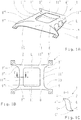
- FIGS. 1A to 1C show various views of a support structure 1 according to an embodiment of the invention, wherein Figure 1A shows a perspective view of the support structure, FIG. 1B a plan view of the support structure and Figure 1C a cut along in FIG. 1B represented line AA.
- the support structure 1 forms an axle carrier or subframe for a motor vehicle.
- the support structure 1 is double-shelled with an upper shell 2 and a lower shell 3 (see in particular FIG FIG. 1C) formed, which are fixedly connected to each other and form a frame member 7.
- the upper shell 2 and the lower shell 3 are each S-shaped (here shown in mirror image upside down), so that the connection of the upper shell 2 to the lower shell 3 at their respective substantially straight upper and lower surfaces 4, 4th ', 5, 5' takes place for example by means of gluing. Between the upper shell 2 and the lower shell 3, a cavity 6 is formed, which, however, also with a material of low density, as described above, may be filled.
- the wall thickness of the upper and lower shell 2, 3 is 4 to 5 mm.
- the frame element 7 is made of a fiber-reinforced plastic and has a substantially quadrangular shape with four corner sections 8, 8 ', 8 ", 8'", wherein of each corner section 8, 8 ', 8 ", 8'” an elastic connection point 9, 9 ', 9 ", 9'” protrudes in the direction transverse to the longitudinal axis L of the motor vehicle.
- the elastic connection points 9, 9 ', 9 ", 9"' which serve as force introduction points, are formed integrally with the frame element 7 by means of textile folding.
- the support structure 1 in the region of the connection to the body, that is tapered at the elastic connection points 9, 9 ', 9 ", 9'” formed or between the upper shell 2 and the lower shell 3 formed cavity 6 is tapered.
- the distance between the upper and the lower shell 2, 3 is in the tapered elastic connection points 9, 9 ', 9 ", 9'” a maximum of 5 mm.
- the upper shell 2 and the lower shell 3 run V-shaped over a length of 10 to 20 cm in an opening distance of 10 cm.
- the support structure 1 has only two elastic connection points 9, 9 '", then the frame part 7 would be approximately at the indicated by the reference numeral 10 dashed line in FIG. 1B so that the elastic connection points 9, 9 '"are connected only by a bow-shaped element, which is here denoted by the reference numeral 11.
- the frame part 7 would be approximately at the indicated by the reference numeral 10 dashed line in FIG. 1B so that the elastic connection points 9, 9 '"are connected only by a bow-shaped element, which is here denoted by the reference numeral 11.
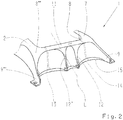
- FIG. 2 shows a perspective view of a front part of a support structure 1 according to an embodiment, wherein the support structure 1 is additionally provided with reinforcing elements 13, which are here designed as reinforcing ribs. Also, the resulting by the textile folding on the underside 15 of the support structure 1 collar 14 may be additionally provided with reinforcing elements.
- the reinforcing elements 13 may be made of plastic molding compounds, in particular of fiber-reinforced thermoplastics or thermosets.
Description
Die Erfindung betrifft eine Trägerstruktur, insbesondere einen Achsträger für ein Kraftfahrzeug, gemäß dem Oberbegriff des Anspruchs 1 sowie ein Verfahren zum Herstellen einer derartigen Trägerstruktur.The invention relates to a support structure, in particular an axle support for a motor vehicle, according to the preamble of
Die gattungsgemäße
Zur Aufnahme von Fahrwerksbauteilen, wie beispielsweise Lenker, Federung, etc., verfügen Kraftfahrzeuge (PKW und LKW) über eine Trägerstruktur in Form eines Achsträgers bzw. Hilfsrahmens. Dieser Achsträger verteilt die Lasten der Fahrwerksbauteile an geeignete Anschlussstellen der Karosserie und bietet dabei gleichzeitig teilweise auch eine elastische Entkopplung des Fahrwerks gegenüber der Karosserie. Die elastische Entkopplung ist besonders vorteilhaft im Hinblick auf den Fahrkomfort und die beim Fahren auftretende Akustik. Darüber hinaus dient der Achsträger auch als Montagehilfe des Fahrwerks als voreingestelltes Modul.For receiving suspension components, such as handlebars, suspension, etc., motor vehicles (cars and trucks) have a support structure in the form of an axle carrier or subframe. This axle carrier distributes the loads of the chassis components to suitable connection points of the body and at the same time offers partial elastic decoupling of the chassis from the bodywork. The elastic decoupling is particularly advantageous in terms of ride comfort and the acoustics occurring during driving. In addition, the axle carrier also serves as a mounting aid for the chassis as a pre-set module.
Im Stand der Technik sind Achsträger bekannt, welche aus metallischen Schweißkonstruktionen, beispielsweise in Stahlblechbauweisen oder in Aluminium-Gussbauweisen kombiniert mit Profilen, bestehen. Darüber hinaus ist es im Stand der Technik ebenfalls bekannt, Achsträger aus faserverstärktem Kunststoff herzustellen.In the prior art axle beams are known, which consist of metallic welded structures, for example in steel sheet construction or in aluminum cast construction combined with profiles. In addition, it is also known in the art to produce fiber reinforced plastic axle beams.
Beispielsweise ist aus
Bisher existiert aufgrund der komplexen Anforderungen im Hinblick auf die mechanischen Eigenschaften, wie Festigkeit und Steifigkeit, an den Krafteinleitungsstellen der bekannten Hilfsrahmen bzw. Achsträger noch keine Lösung für eine wirtschaftliche serienmäßige Herstellung. Insbesondere ist hierbei problematisch, dass die bekannten Konstruktionen elastische Lager beispielsweise in Form von Gummilagern benötigen, welche derart ausgebildet sein müssen, dass sie parallel zu der Fahrzeuglängsachse eine hohe Elastizität aufweisen, jedoch senkrecht zu der Fahrzeuglängsachse eine hohe Steifigkeit aufweisen. Ein zusätzlicher Nachteil im Hinblick auf die bekannten Konstruktionen ist darüber hinaus, dass bei Achsträgern bzw. Hilfsrahmen aus faserverstärktem Kunststoff an den Ecken bei der Herstellung viel überstehendes Material auftritt, welches in einem zusätzlichen Verfahrensschritt entfernt, insbesondere weggeschnitten, werden muss.Until now, due to the complex requirements with regard to the mechanical properties, such as strength and rigidity, at the force introduction points of the known subframe or axle support, there is still no solution for economical series production. In particular, this is problematic in that the known constructions elastic bearings, for example in the form of rubber bearings require, which must be designed such that they have parallel to the vehicle longitudinal axis a high elasticity, but perpendicular to the vehicle longitudinal axis have a high rigidity. An additional disadvantage with regard to the known constructions is moreover that in the case of axle carriers or subframes made of fiber-reinforced plastic at the corners, a great deal of protruding material occurs during production, which must be removed, in particular cut away, in an additional process step.
Daher ist es eine Aufgabe der vorliegenden Erfindung, eine Trägerstruktur, insbesondere einen Achsträger für ein Kraftfahrzeug, bereitzustellen, welche wirtschaftlich herstellbar ist und dennoch die mechanischen Anforderungen, insbesondere an den Krafteinleitungsstellen der Trägerstruktur, erfüllt. Weiterhin ist es eine Aufgabe der vorliegenden Erfindung ein entsprechendes Herstellungsverfahren für eine derartige Trägerstruktur bereitzustellen.It is therefore an object of the present invention to provide a carrier structure, in particular an axle carrier for a motor vehicle, which is economical to produce and nevertheless fulfills the mechanical requirements, in particular at the force introduction points of the carrier structure. Furthermore, it is an object of the present invention to provide a corresponding manufacturing method for such a support structure.
Diese Aufgabe wird durch eine Trägerstruktur mit den Merkmalen gemäß Anspruch 1 und ein Verfahren zum Herstellen einer Trägerstruktur mit den Merkmalen gemäß Anspruch 14 gelöst. Bevorzugte Ausführungsformen der Erfindung sind in den jeweiligen abhängigen Ansprüchen definiert.This object is achieved by a support structure having the features according to
Es wird eine Trägerstruktur, insbesondere ein Achsträger für ein Kraftfahrzeug, bereitgestellt, welche als ein- oder mehrschalig ausgebildetes Rahmenelement aus faserverstärktem Kunststoff hergestellt ist, wobei das Rahmenelement zumindest eine elastische Anschlussstelle zum Anschluss an ein Aggregat aufweist, wobei die zumindest eine elastische Anschlussstelle einstückig mit dem Rahmenelement ausgebildet ist. Durch diese Konfiguration der einstückig mit dem Rahmenelement ausgebildeten elastischen Anschlussstellen kann eine wirtschaftliche Herstellung bei gleichzeitiger Erfüllung der hohen mechanischen Anforderungen an die Trägerstruktur gewährleistet werden. Auch werden durch elastisches Ausbilden der Anschlussstellen selbst zusätzliche Gummilager vermieden, was die Wirtschaftlichkeit des Herstellungsverfahrens weiter verbessert, da einerseits Kosten für die zusätzlichen Gummilager eingespart werden können und andererseits auch ein zusätzlicher Herstellungsschritt zu Montage der Gummilager entfallen kann.It is a support structure, in particular an axle for a motor vehicle, provided which is made as a single or multi-shell frame member made of fiber reinforced plastic, wherein the frame member has at least one elastic connection point for connection to an aggregate, said at least one elastic connection point integral with the frame element is formed. By virtue of this configuration of the elastic connection points formed integrally with the frame element, economic production can be ensured while simultaneously meeting the high mechanical requirements of the support structure. Also, additional rubber bearings are avoided by elastic forming the connection points, which further improves the economy of the manufacturing process, since on the one hand costs for the additional rubber bearings can be saved and on the other hand, an additional manufacturing step to assembly of the rubber bearings can be omitted.
Gemäß einer bevorzugten Ausführungsform weist die Trägerstruktur mindestens zwei elastische Anschlussstellen, insbesondere vier elastische Anschlussstellen auf. Die Zahl der vorgesehenen elastischen Anschlussstellen kann je nach Einsatzgebiet bzw. Anforderungen an die Trägerstruktur variiert werden.According to a preferred embodiment, the support structure has at least two elastic connection points, in particular four elastic connection points. The number of provided elastic connection points can be varied depending on the application or requirements of the support structure.
Gemäß noch einer bevorzugten Ausführungsform ist das Rahmenelement zweischalig mit einer oberen Schale und einer unteren Schale ausgebildet, wobei zwischen der oberen Schale und der unteren Schale ein Hohlraum gebildet ist. Alternativ kann das Rahmenelement jedoch auch einschalig mit einem offenen Profil ausgebildet sein, was Materialkosten einspart und einen zusätzlichen Schritt des Aneinanderfügens, beispielsweise mittels Kleben, der oberen und unteren Schale überflüssig macht.According to yet a preferred embodiment, the frame member is clamshell-shaped with an upper shell and a lower shell, wherein between the upper shell and the lower shell, a cavity is formed. Alternatively, however, the frame element can also be designed as a single-shell with an open profile, which saves material costs and makes an additional step of joining, for example by gluing, the upper and lower shell superfluous.
Vorzugsweise weist das Rahmenelement einen im Wesentlichen S-förmigen Querschnitt auf. Die S-förmige Ausbildung hat den Vorteil, dass bei der Verklebung der oberen und unteren Schale diese auf im Wesentlichen geraden Flächen erfolgen kann.Preferably, the frame member has a substantially S-shaped cross-section. The S-shaped design has the advantage that in the bonding of the upper and lower shell, this can be done on substantially straight surfaces.
Darüber hinaus ist es vorteilhaft, wenn die zumindest eine elastische Anschlussstelle in Richtung einer Längsachse des Kraftfahrzeugs im Wesentlichen elastisch ist und in einer Richtung senkrecht zu der Längsachse im Wesentlichen steif ist. Durch die hohe Elastizität in Fahrzeuglängsrichtung wird eine parallele Verschiebung entlang der Fahrzeuglängsachse nach hinten und vorne ermöglicht, was der Reduzierung der Stößigkeit des Fahrwerks beispielsweise beim Überfahren von Fahrbahnunebenheiten dient. In der Praxis kann die Verschiebung bis zu 6 mm betragen. Weiterhin sei angemerkt, dass die Elastizität in den elastischen Anschlussstellen durch einen geringen Querschnitt und ein geringes Flächenträgheitsmoment der Trägerstruktur im Bereich der elastischen Anschlussstellen erzielt wird. Die hohe Steifigkeit in der Querrichtung wird dagegen durch die Kraftübertragung in der gesamten Fläche, welche als Druck- oder Zugstrebe ausgebildet ist bzw. wirkt, ermöglicht. Dies wird durch einen entsprechenden Verlauf der Fasern in dem Kunststoff in einer Seitenfläche der Trägerstruktur sichergestellt.Moreover, it is advantageous if the at least one elastic connection point is substantially elastic in the direction of a longitudinal axis of the motor vehicle and is substantially rigid in a direction perpendicular to the longitudinal axis. Due to the high elasticity in the vehicle longitudinal direction a parallel displacement along the vehicle longitudinal axis to the rear and front is possible, which serves to reduce the shock of the chassis, for example, when driving over bumps in the road. In practice, the displacement can be up to 6 mm. It should also be noted that the elasticity in the elastic connection points is achieved by a small cross-section and a low area moment of inertia of the support structure in the region of the elastic connection points. By contrast, the high rigidity in the transverse direction is made possible by the transmission of force in the entire surface, which is designed as a pressure or tension strut. This is ensured by a corresponding course of the fibers in the plastic in a side surface of the support structure.
Die zumindest eine elastische Anschlussstelle ist durch textile Faltenbildung gebildet, was das Herstellungsverfahren vereinfacht.The at least one elastic connection point is formed by textile wrinkling, which simplifies the manufacturing process.
Vorzugsweise ist der faserverstärkte Kunststoff mit langfaserigen und/oder endlosfaserigen Kunststofffasern (Organoblech) verstärkt. Insbesondere Endlosfasern sind im Hinblick auf die textile Faltenbildung vorteilhaft.The fiber-reinforced plastic is preferably reinforced with long-fiber and / or continuous-fiber synthetic fibers (organic sheet). In particular, continuous fibers are advantageous in terms of textile wrinkling.
Vorteilhaft ist auch, wenn das Rahmenelement im Bereich der zumindest einen elastischen Anschlussstelle verjüngt ausgebildet ist. Insbesondere ist hierbei in dem Bereich der Anbindung an die Fahrzeugkarosserie je nach Anforderung an die Anschlusssteifigkeit der durch die obere und untere Schale gebildete Hohlraum verjüngt ausgebildet. Dies reduziert die oben erwähnte Stößigkeit des Fahrwerks beim Überfahren von Fahrbahnunebenheiten noch weiter.It is also advantageous if the frame element is designed to be tapered in the region of the at least one elastic connection point. In particular, the cavity formed by the upper and lower shell is tapered in the region of the connection to the vehicle body, depending on the requirements of the connection rigidity. This further reduces the above-mentioned chassis bumpiness when driving over bumps in the road.
Gemäß einer weiteren bevorzugten Ausführungsform weist das Rahmenelement einen im Wesentlichen rechteckigen Körper mit vier Eckabschnitten auf, wobei von jedem Eckabschnitt eine elastische Anschlussstelle in der Richtung quer zur Längsachse des Kraftfahrzeugs abragt. Es ist dabei vorteilhaft, wenn die elastischen Anschlussstellen im Wesentlichen in Fahrzeugquerrichtung angeordnet sind bzw. von der Trägerstruktur abragen, so dass die im Stand der Technik verwendeten Gummilager hierdurch effektiv substituiert werden können und die oben genannten elastischen Eigenschaften in Fahrzeuglängsrichtung erzielt werden können.According to a further preferred embodiment, the frame element has a substantially rectangular body with four corner sections, wherein from each corner section an elastic connection point protrudes in the direction transverse to the longitudinal axis of the motor vehicle. It is advantageous if the elastic connection points are arranged substantially in the vehicle transverse direction or protrude from the support structure, so that the rubber bearings used in the prior art can thereby be effectively substituted and the above-mentioned elastic properties can be achieved in the vehicle longitudinal direction.
Das Rahmenelement kann jedoch alternativ lediglich zwei elastische Anschlussstellen aufweisen, welche dann durch ein bügelartiges Element verbunden sind.However, the frame element may alternatively have only two elastic connection points, which are then connected by a bow-like element.
Ein weiterer Vorteil kann dadurch erzielt werden, dass die Trägerstruktur mit Verstärkungselementen, insbesondere mit Verstärkungsrippen, ausgebildet ist, wobei die Verstärkungselemente aus Kunststoff-Pressmassen, beispielsweise langfaserverstärkte Thermoplaste oder SMC/BMC (Duroplast), hergestellt sind. Hierdurch wird auf vorteilhafte Weise sichergestellt, dass die hohen mechanischen Anforderungen an die Trägerstruktur erfüllt werden können und es nicht zu einem vorzeitigen Versagen der Trägerstruktur kommt. Die Kunststoff-Pressmassen können innen und/oder außen an dem Rahmenelement vorgesehen sein. Die textile Verstärkungsstruktur kann ein Gelege, Gewebe, Gestrick, Gewirk oder eine Matte sein und quasi endlose oder geschnittene Langfasern enthalten. Die textilen Halbzeuge können trocken oder vorimprägniert sein, ein Hybridgarn enthalten oder ein Bindermaterial zum Fixieren trockener Lagen enthalten. Zum Aufbau und Formen trockener textiler Halbzeuge ist der Einsatz thermoplastischer oder reaktiver Binder, beispielsweise auf der Basis einer Harzkomponente, vorteilhaft. Als Harze sind Thermoplaste wie Polyamide (PA), Polysulfone (PS), Polypropylen (PP) oder PEEK einsetzbar. Als Duroplaste sind Epoxid-Harze, Polyurethane, Venylester oder hybride Harzsysteme geeignet. Als Herstellungsprozess ist vorzugsweise ein Heißpressen für vorimprägnierte Halbzeuge und ein Liquid Composite Moulding (LCM) Verfahren (RIM, RTM, etc.) für die Verwendung trockener textiler Halbzeuge implementierbar.Another advantage can be achieved in that the support structure with reinforcing elements, in particular with reinforcing ribs, is formed, wherein the reinforcing elements of plastic molding compounds, such as long fiber reinforced thermoplastics or SMC / BMC (Duroplast), are made. This advantageously ensures that the high mechanical requirements of the support structure can be met and not premature failure the support structure comes. The plastic molding compounds may be provided on the inside and / or outside of the frame member. The textile reinforcing structure may be a scrim, fabric, knit, knit or mat and contain quasi-continuous or cut long fibers. The semi-finished textile products may be dry or preimpregnated, contain a hybrid yarn or contain a binder material for fixing dry layers. For the construction and shaping of dry semi-finished textile products, the use of thermoplastic or reactive binders, for example based on a resin component, is advantageous. Thermoplastics such as polyamides (PA), polysulfones (PS), polypropylene (PP) or PEEK can be used as resins. As thermosets epoxy resins, polyurethanes, Venylester or hybrid resin systems are suitable. As a production process, preferably a hot pressing for preimpregnated semi-finished products and a liquid composite molding (LCM) process (RIM, RTM, etc.) for the use of dry semi-finished textile products can be implemented.
Gemäß einer weiteren bevorzugten Ausführungsform sind die obere Schale und die untere Schale mittels Fügen, insbesondere durch Kleben, Nieten oder Schrauben, oder durch Schweißen miteinander verbunden. Schweißen mittels Ultraschall, Laser oder Vibration ist insbesondere dann vorteilhaft, wenn für die Trägerstruktur thermoplastische Werkstoffe verwendet werden.According to a further preferred embodiment, the upper shell and the lower shell are joined together by means of joining, in particular by gluing, riveting or screwing, or by welding. Welding by means of ultrasound, laser or vibration is particularly advantageous if thermoplastic materials are used for the support structure.
Der Hohlraum kann von einem Material mit geringer Dichte, insbesondere von einem Schaum, Waben oder Balsaholz, ausgefüllt sein. Dies kann im Herstellungsprozess vorteilhafterweise dazu genutzt werden, um die obere und untere Schale in einem Schritt zu Formen.The cavity may be filled by a low-density material, in particular a foam, honeycomb or balsa wood. This can be advantageously used in the manufacturing process to form the upper and lower shell in one step.
Gemäß der Erfindung wird weiterhin ein Verfahren zum Herstellen einer Trägerstruktur bereitgestellt, wobei das Verfahren die folgenden Schritte umfasst: Herstellen eines textilen Halbzeugs oder eines Halbzeugs aus textilverstärktem Kunststoff zur Bildung der Trägerstruktur mit einem im Wesentlichen rechteckigen Körper mit vier Eckabschnitten; Verformen des textilen Halbzeugs bzw. des Halbzeugs aus textilverstärktem Kunststoff von einem ursprünglichen ersten Umfang auf einen gegenüber einer Bezugsebene des textilen Halbzeugs bzw. des Halbzeugs aus textilverstärktem Kunststoff versetzten kleineren zweiten Umfang; Bilden von Falten aus den bei dem Verformungsschritt gestauchten Bereichen, um zumindest zwei, insbesondere vier, elastische Anschlussstellen und weitere durch die Falten gebildete Krafteinleitungsstellen zu formen. Dieses Verfahren ist besonders wirtschaftlich, da, wie oben bereits ausgeführt, zusätzliche Gummilager überflüssig sind und die Trägerstruktur einstückig auf einfache Weise herstellbar ist, da das überschüssige Material der oberen Schale und der unteren Schale nicht mehr weggeschnitten werden muss, sondern in der/den elastischen Anschlussstelle/-n weiterverwendet wird.According to the invention, there is further provided a method for producing a carrier structure, the method comprising the following steps: producing a textile semi-finished product or a semi-finished textile-reinforced plastic to form the carrier structure having a substantially rectangular body with four corner sections; Deformation of the textile semifinished product or semifinished product made of textile-reinforced plastic from an original first circumference to a smaller second circumference offset from a reference plane of the textile semifinished product or semifinished product made of textile-reinforced plastic; Forming wrinkles the areas compressed in the deformation step to form at least two, in particular four, elastic connection points and further force introduction points formed by the folds. This method is particularly economical because, as stated above, additional rubber bearings are superfluous and the support structure is integrally produced in a simple manner, since the excess material of the upper shell and the lower shell no longer needs to be cut away, but in the / the elastic Junction / -n is used.
Vorzugsweise ist der Aufbau der Trägerstruktur mehrlagig, wobei die Lagen in einem sogenannten Preformingprozess in Zwischenschritten fixiert werden.Preferably, the structure of the support structure is multi-layered, wherein the layers are fixed in intermediate steps in a so-called preforming process.
Im Nachfolgenden wird eine Ausführungsform der Erfindung unter Bezugnahme auf die beigefügte Zeichnung näher beschrieben. Es zeigt:
-
Fig. 1A - 1C verschiedene Ansichten einer Trägerstruktur gemäß einer Ausführungsform der Erfindung; und -
Fig. 2 eine perspektivische Ansicht eines vorderen Teils einer Trägerstruktur gemäß einer Ausführungsform.
-
Fig. 1A - 1C various views of a support structure according to an embodiment of the invention; and -
Fig. 2 a perspective view of a front part of a support structure according to an embodiment.
Um eine weitere Reduzierung der Stößigkeit des Fahrwerks wie oben bereits beschrieben zu erreichen, ist die Trägerstruktur 1 in dem Bereich der Anbindung an die Karosserie, also an den elastischen Anschlussstellen 9, 9', 9", 9'" verjüngt ausgebildet bzw. der zwischen der oberen Schale 2 und der unteren Schale 3 ausgebildete Hohlraum 6 wird verjüngt. Der Abstand zwischen der oberen und der unteren Schale 2, 3 beträgt dabei in den verjüngten elastischen Anschlussstellen 9, 9', 9", 9'" maximal 5 mm. Im Verlauf von den jeweiligen elastischen Anschlussstellen 9, 9', 9", 9'" in Richtung zu dem viereckigen Rahmenelement 7 laufen die obere Schale 2 bzw. die untere Schale 3 V-förmig über eine Länge von 10 bis 20 cm in einen Öffnungsabstand von 10 cm.In order to achieve a further reduction of the shock of the chassis as already described above, the
Wenn in einer alternativen Ausführungsform, welche hier im Detail nicht dargestellt ist, die Trägerstruktur 1 lediglich zwei elastische Anschlussstellen 9, 9'" aufweist, dann würde das Rahmenteil 7 in etwa an der durch das Bezugszeichen 10 gekennzeichneten gestrichelten Linie in
Durch Vorsehen der einstückig mit dem Rahmenelement 7 ausgebildeten elastischen Anschlussstellen 9, 9', 9", 9'" wie oben beschrieben, ist das Vorsehen zusätzlicher Gummilager überflüssig. Die durch textile Faltenbildung entlang der Kanten der Trägerstruktur 1 gebildeten Falten 12, 12' (siehe
- 11
- Trägerstruktursupport structure
- 22
- obere Schaleupper shell
- 33
- untere Schalelower shell
- 4, 4'4, 4 '
- obere gerade Flächenupper straight surfaces
- 5, 5'5, 5 '
- untere gerade Flächenlower straight surfaces
- 66
- Hohlraumcavity
- 77
- Rahmenelementframe element
- 8, 8', 8", 8"'8, 8 ', 8 ", 8"'
- Eckabschnittecorner portions
- 9, 9', 9", 9'"9, 9 ', 9 ", 9'"
- elastische Anschlussstelleelastic connection point
- 1010
- gestrichelte Liniedashed line
- 11, 11', 11", 11'"11, 11 ', 11 ", 11'"
- bügelartige Elementebow-shaped elements
- 12, 12'12, 12 '
- Faltenwrinkles
- 1313
- Verstärkungselementreinforcing element
- 1414
- Kragencollar
- 1515
- Unterseitebottom
Claims (14)
- Support structure (1), in particular axial support for a motor vehicle, which is produced as a frame element (7) of single- or multi-shell design and composed of fibre-reinforced plastic, wherein the frame element (7) has at least one elastic connection point (9, 9', 9", 9"') for connection to an assembly, and wherein the at least one elastic connection point (9, 9', 9", 9"') is formed integrally with the frame element (7), characterized in that the at least one elastic connection point (9, 9', 9", 9"') is formed by textile creasing of the fibre-reinforced plastic.
- Support structure (1) according to Claim 1, characterized in that the support structure (1) has at least two elastic connection points (9, 9"'), in particular four elastic connection points (9, 9', 9", 9"').
- Support structure (1) according to Claim 1 or 2, characterized in that the frame element (7) is of two-shell design with an upper shell (2) and a lower shell (3), wherein a cavity (6) is enclosed between the upper shell (2) and the lower shell (3).
- Support structure (1) according to Claim 1 or 2, characterized in that the frame element (7) is of single-shell design with an open profile.
- Support structure (1) according to one of Claims 1 to 4, characterized in that the frame element (7) has a substantially S-shaped cross section.
- Support structure (1) according to one of Claims 1 to 5, characterized in that the at least one elastic connection point (9, 9', 9", 9"') is substantially elastic in the direction of a longitudinal axis (L) of the motor vehicle and is substantially stiff in a direction perpendicular to the longitudinal axis (L).
- Support structure (1) according to one of Claims 1 to 6, characterized in that the fibre-reinforced plastic is reinforced with plastics fibres having long fibres and/or continuous fibres.
- Support structure (1) according to one of Claims 1 to 7, characterized in that the frame element (7) is of tapered design in the region of the at least one elastic connection point (9, 9', 9", 9"').
- Support structure (1) according to one of Claims 1 to 8, characterized in that the frame element (7) has a substantially rectangular body with four corner portions (8, 8', 8", 8"'), wherein an elastic connection point (9, 9', 9", 9"'), protrudes from each corner portion (8, 8', 8", 8"') in the direction transversely with respect to the longitudinal axis (L) of the motor vehicle.
- Support structure (1) according to one of Claims 1 to 8, characterized in that the frame element (7) has two elastic connection point (9, 9"') which are connected by a bow-like element (11).
- Support structure (1) according to one of Claims 1 to 10, characterized in that the support structure (1) is formed with reinforcing elements (13), in particular with reinforcing ribs, wherein the reinforcing elements (13) are produced from plastics moulding materials, in particular from fibre-reinforced thermoplastics or thermosetting plastics.
- Support structure (1) according to Claim 3, characterized in that the upper shell (2) and the lower shell (3) are connected to each other by means of joining, in particular by means of adhesive bonding, riveting or screwing, or by welding.
- Support structure (1) according to either of Claims 3 and 12, characterized in that the cavity (6) is filled by a material of low density, in particular by foam, honeycomb or balsa wood.
- Method of producing a support structure (1) in particular according to one of Claims 1 to 13, wherein the method comprises the following steps:- producing a textile semi-finished product or a semi-finished product composed of textile-reinforced plastic in order to form the support structure (1) with a frame element (7) which has at least two corner portions, in particular four corner portions;- deforming the textile semi-finished product or the semi-finished product composed of textile-reinforced plastic from an original first circumference to a smaller second circumference which is offset in relation to a reference plane of the textile semi-finished product or the semi-finished product composed of textile-reinforced plastic;- forming creases (12, 12', 9, 9', 9", 9"') from the regions compressed during the deformation step in order to form at least two, in particular four, elastic connection points (9, 9', 9", 9"') and further force introduction points formed by the creases (12, 12').
Applications Claiming Priority (2)
| Application Number | Priority Date | Filing Date | Title |
|---|---|---|---|
| DE102013201075.3A DE102013201075A1 (en) | 2013-01-24 | 2013-01-24 | Carrier structure and method for producing a carrier structure |
| PCT/EP2013/074005 WO2014114381A1 (en) | 2013-01-24 | 2013-11-18 | Support structure and method of producing a support structure |
Publications (2)
| Publication Number | Publication Date |
|---|---|
| EP2948362A1 EP2948362A1 (en) | 2015-12-02 |
| EP2948362B1 true EP2948362B1 (en) | 2017-03-01 |
Family
ID=49619920
Family Applications (1)
| Application Number | Title | Priority Date | Filing Date |
|---|---|---|---|
| EP13792667.1A Active EP2948362B1 (en) | 2013-01-24 | 2013-11-18 | Support structure and method of producing a support structure |
Country Status (5)
| Country | Link |
|---|---|
| US (1) | US9517797B2 (en) |
| EP (1) | EP2948362B1 (en) |
| CN (1) | CN105073558B (en) |
| DE (1) | DE102013201075A1 (en) |
| WO (1) | WO2014114381A1 (en) |
Families Citing this family (5)
| Publication number | Priority date | Publication date | Assignee | Title |
|---|---|---|---|---|
| DE102014112090A1 (en) * | 2014-08-25 | 2016-02-25 | Benteler Automobiltechnik Gmbh | Achsträger for a motor vehicle and method for producing an axle carrier |
| JP6332260B2 (en) | 2015-12-25 | 2018-05-30 | トヨタ自動車株式会社 | Reinforcement structure for vehicle frame members |
| DE102016107740B4 (en) * | 2016-04-26 | 2018-02-15 | Benteler Automobiltechnik Gmbh | Axle carrier with improved load path |
| DE102016219778A1 (en) * | 2016-10-12 | 2018-04-12 | Ford Global Technologies, Llc | Chassis component for a motor vehicle with at least one integrated vibration isolator and method for producing the chassis component and motor vehicle with such a chassis component |
| DE102017103663A1 (en) * | 2017-02-22 | 2018-08-23 | Benteler Automobiltechnik Gmbh | Achsträger for arrangement on an electric motor vehicle and method for its production |
Family Cites Families (17)
| Publication number | Priority date | Publication date | Assignee | Title |
|---|---|---|---|---|
| FR2129225A5 (en) | 1971-03-19 | 1972-10-27 | Patin Pierre | |
| DE3243434C2 (en) * | 1982-11-24 | 1986-10-23 | Audi AG, 8070 Ingolstadt | Independent wheel suspension for the rear wheels of a motor vehicle |
| IT1231870B (en) * | 1989-03-13 | 1992-01-14 | Fiat Auto Spa | AUXILIARY CHASSIS FOR THE SUPPORT OF THE MOTOR VEHICLE GROUP |
| EP0594131A1 (en) * | 1992-10-21 | 1994-04-27 | The Budd Company | Composite chassis structure and method of manufacture |
| EP0670257B1 (en) * | 1994-02-24 | 1998-04-01 | Max Horlacher | Lightweight vehicle |
| SE503705C2 (en) | 1994-10-25 | 1996-08-05 | Volvo Ab | Load-bearing structure for use in a vehicle body |
| DE19750225A1 (en) * | 1997-11-13 | 1999-05-27 | Daimler Chrysler Ag | Guide for a motor vehicle wheel |
| SE525912C2 (en) * | 2000-05-18 | 2005-05-24 | Volvo Personvagnar Ab | Wheel suspension for a vehicle |
| US20020153648A1 (en) * | 2000-06-30 | 2002-10-24 | Lawson Robert C. | Manufacturing method for composite transverse leaf spring |
| DE10351574C5 (en) * | 2003-11-05 | 2019-11-28 | Bayerische Motoren Werke Aktiengesellschaft | Method for changing the self-steering behavior of the rear wheels of a two-lane motor vehicle |
| JP4550673B2 (en) * | 2005-06-17 | 2010-09-22 | 本田技研工業株式会社 | Vehicle subframe |
| FR2926248B1 (en) * | 2008-01-16 | 2011-11-04 | Peugeot Citroen Automobiles Sa | UNDER VEHICLE ROLLER ASSEMBLY |
| DE102011102467A1 (en) | 2011-05-24 | 2012-11-29 | Audi Ag | Axle carrier for a motor vehicle |
| DE102011077336A1 (en) * | 2011-06-10 | 2012-12-13 | Zf Friedrichshafen Ag | Wheel suspension element comprising at least one support structure and a handlebar |
| DE102011079654A1 (en) * | 2011-07-22 | 2013-01-24 | Zf Friedrichshafen Ag | Four-point link |
| DE102011083173A1 (en) * | 2011-09-22 | 2013-03-28 | Zf Friedrichshafen Ag | Supporting structure for axle of vehicle, particularly for use in automobile industry, has connecting rod for guiding wheel support, where connecting structural component is made of isotropic or quasi-isotropic material |
| EP2578473A1 (en) | 2011-10-06 | 2013-04-10 | SMP Deutschland GmbH | Subframe for motor vehicle |
-
2013
- 2013-01-24 DE DE102013201075.3A patent/DE102013201075A1/en not_active Withdrawn
- 2013-11-18 US US14/759,431 patent/US9517797B2/en active Active
- 2013-11-18 CN CN201380070817.XA patent/CN105073558B/en active Active
- 2013-11-18 WO PCT/EP2013/074005 patent/WO2014114381A1/en active Application Filing
- 2013-11-18 EP EP13792667.1A patent/EP2948362B1/en active Active
Also Published As
| Publication number | Publication date |
|---|---|
| CN105073558B (en) | 2017-07-07 |
| US9517797B2 (en) | 2016-12-13 |
| DE102013201075A1 (en) | 2014-07-24 |
| WO2014114381A1 (en) | 2014-07-31 |
| EP2948362A1 (en) | 2015-12-02 |
| US20150353135A1 (en) | 2015-12-10 |
| CN105073558A (en) | 2015-11-18 |
Similar Documents
| Publication | Publication Date | Title |
|---|---|---|
| EP2651751B1 (en) | Body module component, and method for the production thereof | |
| EP2948362B1 (en) | Support structure and method of producing a support structure | |
| EP2527231A2 (en) | Axle craddle for motor vehicles made of a fiber reinforced plastic | |
| DE102016122663A1 (en) | Impact absorption unit, manufacturing method thereof and element connection structure | |
| DE10022360A1 (en) | Composite component, used for structural use in vehicles and machines, comprises profiles with reinforcing elements at the joints between them and thermoplastic shrunk or injected into the joint area | |
| DE102008020527A1 (en) | Frame structure for a motor vehicle | |
| DE102007053120A1 (en) | Vehicle-wheel carrier e.g. pivot bearing, manufacturing method, involves strengthening cup-shaped or tub shaped base structure of wheel carriers from laminar textile by matrix components, where textile is formed from fiber material | |
| WO2001028845A1 (en) | Fiber-reinforced thermoplastic vehicle cell | |
| WO2014060212A1 (en) | Component for a chassis of a vehicle | |
| DE102010053850A1 (en) | Motor vehicle body with stiffening struts | |
| WO2009149778A1 (en) | Bodyshell structure for a motor vehicle and method for the production thereof | |
| EP1022164B1 (en) | Towing device and hitch | |
| DE102017124391A1 (en) | Threshold component for the sill of a vehicle body | |
| DE102018207221A1 (en) | Energy absorption component for the arrangement in a hollow profile-like sill | |
| DE102010013344A1 (en) | Shell part for e.g. bonnet of motor car, has support frame whose structure is formed by profiles made of fiber reinforced plastic, where profiles are assembled in node devices, and shell element fixed and partly spanned to support frame | |
| DE102013223519A1 (en) | Fiber-plastic composite component and method for producing a fiber-plastic composite component, in particular a body component for a motor vehicle | |
| DE102008032334A1 (en) | Roof module for motor vehicle, has fibrous structure layer provided in sections between reinforcing layer and inner lining, sealing lip formed at outer edges of external layer, where reinforcing layer is made of polyurethane material | |
| DE102017006057B4 (en) | Crash element | |
| EP1500578B1 (en) | Module support and method for its compression moulding | |
| DE102017210205B4 (en) | Two-point link for a vehicle | |
| DE102016223321B4 (en) | Process for manufacturing a link, and link and wheel suspension | |
| EP3677418B1 (en) | Fuselage component for an aircraft, method for producing a fuselage component and aircraft | |
| WO2018158031A1 (en) | Method for producing a leaf spring, and leaf spring and wheel suspension | |
| DE102016102258A1 (en) | Component, in particular for a support structure in a motor vehicle and method for its construction | |
| EP3865380B1 (en) | Plate-shaped structural element and body for a leisure vehicle with such a structural element |
Legal Events
| Date | Code | Title | Description |
|---|---|---|---|
| PUAI | Public reference made under article 153(3) epc to a published international application that has entered the european phase |
Free format text: ORIGINAL CODE: 0009012 |
|
| 17P | Request for examination filed |
Effective date: 20150622 |
|
| AK | Designated contracting states |
Kind code of ref document: A1 Designated state(s): AL AT BE BG CH CY CZ DE DK EE ES FI FR GB GR HR HU IE IS IT LI LT LU LV MC MK MT NL NO PL PT RO RS SE SI SK SM TR |
|
| AX | Request for extension of the european patent |
Extension state: BA ME |
|
| DAX | Request for extension of the european patent (deleted) | ||
| GRAP | Despatch of communication of intention to grant a patent |
Free format text: ORIGINAL CODE: EPIDOSNIGR1 |
|
| INTG | Intention to grant announced |
Effective date: 20161010 |
|
| GRAS | Grant fee paid |
Free format text: ORIGINAL CODE: EPIDOSNIGR3 |
|
| GRAA | (expected) grant |
Free format text: ORIGINAL CODE: 0009210 |
|
| AK | Designated contracting states |
Kind code of ref document: B1 Designated state(s): AL AT BE BG CH CY CZ DE DK EE ES FI FR GB GR HR HU IE IS IT LI LT LU LV MC MK MT NL NO PL PT RO RS SE SI SK SM TR |
|
| REG | Reference to a national code |
Ref country code: GB Ref legal event code: FG4D Free format text: NOT ENGLISH |
|
| REG | Reference to a national code |
Ref country code: CH Ref legal event code: EP Ref country code: AT Ref legal event code: REF Ref document number: 870913 Country of ref document: AT Kind code of ref document: T Effective date: 20170315 |
|
| REG | Reference to a national code |
Ref country code: IE Ref legal event code: FG4D Free format text: LANGUAGE OF EP DOCUMENT: GERMAN |
|
| REG | Reference to a national code |
Ref country code: DE Ref legal event code: R096 Ref document number: 502013006553 Country of ref document: DE |
|
| REG | Reference to a national code |
Ref country code: NL Ref legal event code: MP Effective date: 20170301 |
|
| REG | Reference to a national code |
Ref country code: LT Ref legal event code: MG4D |
|
| PG25 | Lapsed in a contracting state [announced via postgrant information from national office to epo] |
Ref country code: FI Free format text: LAPSE BECAUSE OF FAILURE TO SUBMIT A TRANSLATION OF THE DESCRIPTION OR TO PAY THE FEE WITHIN THE PRESCRIBED TIME-LIMIT Effective date: 20170301 Ref country code: NO Free format text: LAPSE BECAUSE OF FAILURE TO SUBMIT A TRANSLATION OF THE DESCRIPTION OR TO PAY THE FEE WITHIN THE PRESCRIBED TIME-LIMIT Effective date: 20170601 Ref country code: GR Free format text: LAPSE BECAUSE OF FAILURE TO SUBMIT A TRANSLATION OF THE DESCRIPTION OR TO PAY THE FEE WITHIN THE PRESCRIBED TIME-LIMIT Effective date: 20170602 Ref country code: HR Free format text: LAPSE BECAUSE OF FAILURE TO SUBMIT A TRANSLATION OF THE DESCRIPTION OR TO PAY THE FEE WITHIN THE PRESCRIBED TIME-LIMIT Effective date: 20170301 Ref country code: LT Free format text: LAPSE BECAUSE OF FAILURE TO SUBMIT A TRANSLATION OF THE DESCRIPTION OR TO PAY THE FEE WITHIN THE PRESCRIBED TIME-LIMIT Effective date: 20170301 |
|
| PG25 | Lapsed in a contracting state [announced via postgrant information from national office to epo] |
Ref country code: RS Free format text: LAPSE BECAUSE OF FAILURE TO SUBMIT A TRANSLATION OF THE DESCRIPTION OR TO PAY THE FEE WITHIN THE PRESCRIBED TIME-LIMIT Effective date: 20170301 Ref country code: SE Free format text: LAPSE BECAUSE OF FAILURE TO SUBMIT A TRANSLATION OF THE DESCRIPTION OR TO PAY THE FEE WITHIN THE PRESCRIBED TIME-LIMIT Effective date: 20170301 Ref country code: ES Free format text: LAPSE BECAUSE OF FAILURE TO SUBMIT A TRANSLATION OF THE DESCRIPTION OR TO PAY THE FEE WITHIN THE PRESCRIBED TIME-LIMIT Effective date: 20170301 Ref country code: LV Free format text: LAPSE BECAUSE OF FAILURE TO SUBMIT A TRANSLATION OF THE DESCRIPTION OR TO PAY THE FEE WITHIN THE PRESCRIBED TIME-LIMIT Effective date: 20170301 Ref country code: BG Free format text: LAPSE BECAUSE OF FAILURE TO SUBMIT A TRANSLATION OF THE DESCRIPTION OR TO PAY THE FEE WITHIN THE PRESCRIBED TIME-LIMIT Effective date: 20170601 |
|
| PG25 | Lapsed in a contracting state [announced via postgrant information from national office to epo] |
Ref country code: NL Free format text: LAPSE BECAUSE OF FAILURE TO SUBMIT A TRANSLATION OF THE DESCRIPTION OR TO PAY THE FEE WITHIN THE PRESCRIBED TIME-LIMIT Effective date: 20170301 |
|
| PG25 | Lapsed in a contracting state [announced via postgrant information from national office to epo] |
Ref country code: EE Free format text: LAPSE BECAUSE OF FAILURE TO SUBMIT A TRANSLATION OF THE DESCRIPTION OR TO PAY THE FEE WITHIN THE PRESCRIBED TIME-LIMIT Effective date: 20170301 Ref country code: IT Free format text: LAPSE BECAUSE OF FAILURE TO SUBMIT A TRANSLATION OF THE DESCRIPTION OR TO PAY THE FEE WITHIN THE PRESCRIBED TIME-LIMIT Effective date: 20170301 Ref country code: RO Free format text: LAPSE BECAUSE OF FAILURE TO SUBMIT A TRANSLATION OF THE DESCRIPTION OR TO PAY THE FEE WITHIN THE PRESCRIBED TIME-LIMIT Effective date: 20170301 Ref country code: CZ Free format text: LAPSE BECAUSE OF FAILURE TO SUBMIT A TRANSLATION OF THE DESCRIPTION OR TO PAY THE FEE WITHIN THE PRESCRIBED TIME-LIMIT Effective date: 20170301 Ref country code: SK Free format text: LAPSE BECAUSE OF FAILURE TO SUBMIT A TRANSLATION OF THE DESCRIPTION OR TO PAY THE FEE WITHIN THE PRESCRIBED TIME-LIMIT Effective date: 20170301 |
|
| PG25 | Lapsed in a contracting state [announced via postgrant information from national office to epo] |
Ref country code: IS Free format text: LAPSE BECAUSE OF FAILURE TO SUBMIT A TRANSLATION OF THE DESCRIPTION OR TO PAY THE FEE WITHIN THE PRESCRIBED TIME-LIMIT Effective date: 20170701 Ref country code: PL Free format text: LAPSE BECAUSE OF FAILURE TO SUBMIT A TRANSLATION OF THE DESCRIPTION OR TO PAY THE FEE WITHIN THE PRESCRIBED TIME-LIMIT Effective date: 20170301 Ref country code: SM Free format text: LAPSE BECAUSE OF FAILURE TO SUBMIT A TRANSLATION OF THE DESCRIPTION OR TO PAY THE FEE WITHIN THE PRESCRIBED TIME-LIMIT Effective date: 20170301 Ref country code: PT Free format text: LAPSE BECAUSE OF FAILURE TO SUBMIT A TRANSLATION OF THE DESCRIPTION OR TO PAY THE FEE WITHIN THE PRESCRIBED TIME-LIMIT Effective date: 20170703 |
|
| REG | Reference to a national code |
Ref country code: DE Ref legal event code: R097 Ref document number: 502013006553 Country of ref document: DE |
|
| PLBE | No opposition filed within time limit |
Free format text: ORIGINAL CODE: 0009261 |
|
| STAA | Information on the status of an ep patent application or granted ep patent |
Free format text: STATUS: NO OPPOSITION FILED WITHIN TIME LIMIT |
|
| PG25 | Lapsed in a contracting state [announced via postgrant information from national office to epo] |
Ref country code: DK Free format text: LAPSE BECAUSE OF FAILURE TO SUBMIT A TRANSLATION OF THE DESCRIPTION OR TO PAY THE FEE WITHIN THE PRESCRIBED TIME-LIMIT Effective date: 20170301 |
|
| 26N | No opposition filed |
Effective date: 20171204 |
|
| PG25 | Lapsed in a contracting state [announced via postgrant information from national office to epo] |
Ref country code: SI Free format text: LAPSE BECAUSE OF FAILURE TO SUBMIT A TRANSLATION OF THE DESCRIPTION OR TO PAY THE FEE WITHIN THE PRESCRIBED TIME-LIMIT Effective date: 20170301 |
|
| PG25 | Lapsed in a contracting state [announced via postgrant information from national office to epo] |
Ref country code: MC Free format text: LAPSE BECAUSE OF FAILURE TO SUBMIT A TRANSLATION OF THE DESCRIPTION OR TO PAY THE FEE WITHIN THE PRESCRIBED TIME-LIMIT Effective date: 20170301 |
|
| GBPC | Gb: european patent ceased through non-payment of renewal fee |
Effective date: 20171118 |
|
| PG25 | Lapsed in a contracting state [announced via postgrant information from national office to epo] |
Ref country code: LI Free format text: LAPSE BECAUSE OF NON-PAYMENT OF DUE FEES Effective date: 20171130 Ref country code: CH Free format text: LAPSE BECAUSE OF NON-PAYMENT OF DUE FEES Effective date: 20171130 |
|
| PG25 | Lapsed in a contracting state [announced via postgrant information from national office to epo] |
Ref country code: LU Free format text: LAPSE BECAUSE OF NON-PAYMENT OF DUE FEES Effective date: 20171118 |
|
| REG | Reference to a national code |
Ref country code: FR Ref legal event code: ST Effective date: 20180731 Ref country code: BE Ref legal event code: MM Effective date: 20171130 |
|
| REG | Reference to a national code |
Ref country code: IE Ref legal event code: MM4A |
|
| PG25 | Lapsed in a contracting state [announced via postgrant information from national office to epo] |
Ref country code: MT Free format text: LAPSE BECAUSE OF FAILURE TO SUBMIT A TRANSLATION OF THE DESCRIPTION OR TO PAY THE FEE WITHIN THE PRESCRIBED TIME-LIMIT Effective date: 20170301 |
|
| PG25 | Lapsed in a contracting state [announced via postgrant information from national office to epo] |
Ref country code: FR Free format text: LAPSE BECAUSE OF NON-PAYMENT OF DUE FEES Effective date: 20171130 Ref country code: IE Free format text: LAPSE BECAUSE OF NON-PAYMENT OF DUE FEES Effective date: 20171118 |
|
| PG25 | Lapsed in a contracting state [announced via postgrant information from national office to epo] |
Ref country code: BE Free format text: LAPSE BECAUSE OF NON-PAYMENT OF DUE FEES Effective date: 20171130 Ref country code: GB Free format text: LAPSE BECAUSE OF NON-PAYMENT OF DUE FEES Effective date: 20171118 |
|
| PG25 | Lapsed in a contracting state [announced via postgrant information from national office to epo] |
Ref country code: HU Free format text: LAPSE BECAUSE OF FAILURE TO SUBMIT A TRANSLATION OF THE DESCRIPTION OR TO PAY THE FEE WITHIN THE PRESCRIBED TIME-LIMIT; INVALID AB INITIO Effective date: 20131118 |
|
| PG25 | Lapsed in a contracting state [announced via postgrant information from national office to epo] |
Ref country code: CY Free format text: LAPSE BECAUSE OF FAILURE TO SUBMIT A TRANSLATION OF THE DESCRIPTION OR TO PAY THE FEE WITHIN THE PRESCRIBED TIME-LIMIT Effective date: 20170301 |
|
| PG25 | Lapsed in a contracting state [announced via postgrant information from national office to epo] |
Ref country code: MK Free format text: LAPSE BECAUSE OF FAILURE TO SUBMIT A TRANSLATION OF THE DESCRIPTION OR TO PAY THE FEE WITHIN THE PRESCRIBED TIME-LIMIT Effective date: 20170301 |
|
| REG | Reference to a national code |
Ref country code: AT Ref legal event code: MM01 Ref document number: 870913 Country of ref document: AT Kind code of ref document: T Effective date: 20181118 |
|
| PG25 | Lapsed in a contracting state [announced via postgrant information from national office to epo] |
Ref country code: AT Free format text: LAPSE BECAUSE OF NON-PAYMENT OF DUE FEES Effective date: 20181118 |
|
| PG25 | Lapsed in a contracting state [announced via postgrant information from national office to epo] |
Ref country code: TR Free format text: LAPSE BECAUSE OF FAILURE TO SUBMIT A TRANSLATION OF THE DESCRIPTION OR TO PAY THE FEE WITHIN THE PRESCRIBED TIME-LIMIT Effective date: 20170301 |
|
| PG25 | Lapsed in a contracting state [announced via postgrant information from national office to epo] |
Ref country code: AL Free format text: LAPSE BECAUSE OF FAILURE TO SUBMIT A TRANSLATION OF THE DESCRIPTION OR TO PAY THE FEE WITHIN THE PRESCRIBED TIME-LIMIT Effective date: 20170301 |
|
| P01 | Opt-out of the competence of the unified patent court (upc) registered |
Effective date: 20230528 |
|
| PGFP | Annual fee paid to national office [announced via postgrant information from national office to epo] |
Ref country code: DE Payment date: 20230926 Year of fee payment: 11 |