EP2948205B1 - Drive mechanism for drug delivery pumps with integrated status indication - Google Patents
Drive mechanism for drug delivery pumps with integrated status indication Download PDFInfo
- Publication number
- EP2948205B1 EP2948205B1 EP14705619.6A EP14705619A EP2948205B1 EP 2948205 B1 EP2948205 B1 EP 2948205B1 EP 14705619 A EP14705619 A EP 14705619A EP 2948205 B1 EP2948205 B1 EP 2948205B1
- Authority
- EP
- European Patent Office
- Prior art keywords
- piston
- drive mechanism
- drug
- disposed
- drug pump
- Prior art date
- Legal status (The legal status is an assumption and is not a legal conclusion. Google has not performed a legal analysis and makes no representation as to the accuracy of the status listed.)
- Active
Links
Images


Classifications
-
- A—HUMAN NECESSITIES
- A61—MEDICAL OR VETERINARY SCIENCE; HYGIENE
- A61M—DEVICES FOR INTRODUCING MEDIA INTO, OR ONTO, THE BODY; DEVICES FOR TRANSDUCING BODY MEDIA OR FOR TAKING MEDIA FROM THE BODY; DEVICES FOR PRODUCING OR ENDING SLEEP OR STUPOR
- A61M5/00—Devices for bringing media into the body in a subcutaneous, intra-vascular or intramuscular way; Accessories therefor, e.g. filling or cleaning devices, arm-rests
- A61M5/14—Infusion devices, e.g. infusing by gravity; Blood infusion; Accessories therefor
- A61M5/142—Pressure infusion, e.g. using pumps
- A61M5/145—Pressure infusion, e.g. using pumps using pressurised reservoirs, e.g. pressurised by means of pistons
- A61M5/1452—Pressure infusion, e.g. using pumps using pressurised reservoirs, e.g. pressurised by means of pistons pressurised by means of pistons
- A61M5/1454—Pressure infusion, e.g. using pumps using pressurised reservoirs, e.g. pressurised by means of pistons pressurised by means of pistons spring-actuated, e.g. by a clockwork
-
- A—HUMAN NECESSITIES
- A61—MEDICAL OR VETERINARY SCIENCE; HYGIENE
- A61M—DEVICES FOR INTRODUCING MEDIA INTO, OR ONTO, THE BODY; DEVICES FOR TRANSDUCING BODY MEDIA OR FOR TAKING MEDIA FROM THE BODY; DEVICES FOR PRODUCING OR ENDING SLEEP OR STUPOR
- A61M5/00—Devices for bringing media into the body in a subcutaneous, intra-vascular or intramuscular way; Accessories therefor, e.g. filling or cleaning devices, arm-rests
- A61M5/14—Infusion devices, e.g. infusing by gravity; Blood infusion; Accessories therefor
- A61M5/142—Pressure infusion, e.g. using pumps
- A61M5/145—Pressure infusion, e.g. using pumps using pressurised reservoirs, e.g. pressurised by means of pistons
- A61M5/1452—Pressure infusion, e.g. using pumps using pressurised reservoirs, e.g. pressurised by means of pistons pressurised by means of pistons
- A61M5/14566—Pressure infusion, e.g. using pumps using pressurised reservoirs, e.g. pressurised by means of pistons pressurised by means of pistons with a replaceable reservoir for receiving a piston rod of the pump
-
- A—HUMAN NECESSITIES
- A61—MEDICAL OR VETERINARY SCIENCE; HYGIENE
- A61M—DEVICES FOR INTRODUCING MEDIA INTO, OR ONTO, THE BODY; DEVICES FOR TRANSDUCING BODY MEDIA OR FOR TAKING MEDIA FROM THE BODY; DEVICES FOR PRODUCING OR ENDING SLEEP OR STUPOR
- A61M2205/00—General characteristics of the apparatus
- A61M2205/58—Means for facilitating use, e.g. by people with impaired vision
Definitions
- THIS INVENTION relates to drug delivery pumps. More particularly, this invention relates to drive mechanisms with integrated status indication and drug delivery pumps with status integrated drive mechanisms. Methods of operating such devices, and the methods of assembling such devices are also described.
- Parenteral delivery of various drugs i.e., delivery by means other than through the digestive track, has become a desired method of drug delivery for a number of reasons.
- This form of drug delivery by injection may enhance the effect of the substance being delivered and ensure that the unaltered medicine reaches its intended site at a significant concentration.
- undesired side effects associated with other routes of delivery such as systemic toxicity, can potentially be avoided through parenteral delivery.
- By bypassing the digestive system of a mammalian patient one can avoid degradation of the active ingredients caused by the catalytic enzymes in the digestive tract and liver and ensure that a necessary amount of drug, at a desired concentration, reaches the targeted site.
- parenteral delivery of liquid medicines into the body has been accomplished by administering bolus injections using a needle and reservoir, continuously by gravity driven dispensers, or via transdermal patch technologies.
- Bolus injections often imperfectly match the clinical needs of the patient, and usually require larger individual doses than are desired at the specific time they are given.
- Continuous delivery of medicine through gravity-feed systems compromises the patient's mobility and lifestyle, and limits the therapy to simplistic flow rates and profiles.
- Another form of drug delivery, transdermal patches similarly has its restrictions. Transdermal patches often require specific molecular drug structures for efficacy, and the control of the drug administration through a transdermal patch is severely limited.
- Ambulatory infusion pumps have been developed for delivering liquid medicaments to a patient. These infusion devices have the ability to offer sophisticated fluid delivery profiles accomplishing bolus requirements, continuous infusion and variable flow rate delivery. These infusion capabilities usually result in better efficacy of the drug and therapy and less toxicity to the patient's system.
- ambulatory infusion devices are expensive, difficult to program and prepare for infusion, and tend to be bulky, heavy and very fragile. Filling these devices can be difficult and require the patient to carry both the intended medication as well as filling accessories. The devices often require specialized care, maintenance, and cleaning to assure proper functionality and safety for their intended long-term use, and are not cost-effective for patients or healthcare providers.
- pump type delivery devices can be significantly more convenient to a patient, in that doses of the drug may be calculated and delivered automatically to a patient at any time during the day or night.
- pumps may be automatically controlled to provide appropriate doses of a fluidic medium at appropriate times of need, based on sensed or monitored metabolic levels.
- pump type delivery devices have become an important aspect of modern medical treatments of various types of medical conditions, such as diabetes, and the like.
- a fluid delivery device comprising a housing having a fluid reservoir.
- a needle is in fluid communication with the fluid reservoir in an engaged position and out of fluid communication with the fluid reservoir in armed and storage positions.
- a proximal end of a biasing member is coupled to the housing and a distal end of the biasing member is configured to deliver a force to the fluid reservoir.
- a piston member extends through the biasing member and is coupled to the distal end of the biasing member. The piston member is fixed with respect to the housing in a locked position such that the biasing member does not deliver the force to the fluid reservoir and moveable with respect to the housing in a released position such that the biasing member delivers the force to the fluid reservoir. Transitioning the needle from the storage position to the armed position transitions the piston from the locked position to the released position.
- a medicament delivery device comprising a housing for holding a medicament cartridge, a drive and a drive control means.
- the medicament cartridge has a medicament outlet and a bung able to be driven via a piston rod driven by the drive force of the drive and controlled by the drive control means.
- the medicament delivery device comprises a restraining means for applying a restraining force to the piston rod, in a direction opposite to the drive force. By varying the restraining force by the drive control means the movement of the bung along the medicament cartridge can be controlled.
- the drive mechanism includes a drive housing, a status switch interconnect, a drive biasing member, a piston, and a drug container having a cap, a pierceable seal, a barrel, and a plunger seal, wherein the drive biasing member is configured to bear upon an interface surface of the piston.
- the drive mechanism may include an incremental status stem having a stem interconnect, wherein the stem resides within the drive housing and the piston, and wherein the stem has an interconnect which engages one or more contacts on the piston to provide incremental feedback.
- a drug delivery pump with integrated status indication is also disclosed and includes a housing and an assembly platform, upon which an activation mechanism, an insertion mechanism, a fluid pathway connection, a power and control system, and the drive mechanism having a drug container may be mounted.
- the present invention provides drive mechanisms with integrated status indication and drug delivery pumps which incorporate such drive mechanisms. Methods of operating such devices, and methods of assembling such devices are also described.
- the drive mechanisms of the present invention provide integrated status indication features which provide feedback to the user before, during, and after drug delivery. For example, the user may be provided with an initial feedback to identify that the system is operational and ready for drug delivery. Upon activation, the system may then provide one or more drug delivery status indications to the user. At completion of drug delivery, the drive mechanism and drug pump may provide an end-of-dose indication. As the end-of-dose indication is tied to the piston reaching the end of its axial translation, the drive mechanism and drug pump provide a true end-of-dose indication to the user.
- embodiments of the present invention provide end-of-dose compliance to ensure that substantially the entire drug dose has been delivered to the user and that the status indication features have been properly contacted to provide accurate feedback to the user. Through these mechanisms, confirmation of drug dose delivery can accurately be provided to the user or administrator. Accordingly, the novel devices of the present invention alleviate one or more of the problems associated with prior art devices, such as those referred to above.
- a drug pump drive mechanism having the features of claim 1.
- the present invention provides a drive mechanism having integrated status indication which includes: a drive housing, a status switch interconnect, a drive biasing member, a piston, and a drug container having a cap, a pierceable seal, a barrel, and a plunger seal.
- the drive biasing member may be configured to bear upon an interface surface of the piston.
- the drug container may preferably contain a drug fluid for delivery to the user.
- the drive mechanism may further include a connection mount attached to the pierceable seal.
- a cover sleeve may be utilized between the drive biasing member and the interface surface of the piston to, for example, provide more even distribution of force from the biasing member to the piston.
- a contact sleeve may be slidably mounted to the drive housing through an axial aperture of the drive housing, such that sleeve hooks at a distal end of the contact sleeve are caused to contact the piston between the interface surface and a contact protrusion near the proximal end of the piston.
- the piston may also include a locking groove, between the contact protrusion and the proximal end of the piston.
- the contact sleeve may have a radially extending ring at its proximal end, upon which reside one or more flex prongs.
- the drive mechanism may further include one or more contact surfaces located on corresponding components.
- Such contact surfaces may be electrical contact surfaces, mechanical contact surfaces, or electro-mechanical contact surfaces. Such surfaces may initially be in contact and caused to disengage, or initially be disconnected and caused to engage, to permit a signal to be sent to and/or from the power control system.
- the contact surfaces may be electrical contact surfaces which are initially disconnected and caused to come into engagement whereby, upon such engagement, the contact surfaces are capable of continuing an energy pathway or otherwise relaying a signal to the power and control system.
- the contact surfaces are mechanical contact surfaces which are initially in contact and caused to disengage whereby, upon such disengagement, such disengagement is communicated to the power and control system.
- Such signals may be transferred across one or more interconnects to the power and control system or by mechanical action to the power and control system.
- Such components may be utilized within the drive mechanism to measure and relay information related to the status of operation of the drive mechanism, which may be converted by the power and control system into tactile, auditory, and/or visual feedback to the user.
- the motion of the components which permits transmission of a signal to the power control system is enabled by a biasing member axially translating a contact sleeve in the distal direction during operation of the device.
- the drive mechanism may include a piston extension slidably mounted at a distal end and within an axial pass-through of piston; a piston extension biasing member, which is mounted within the axial pass-through of piston and initially compressed between the piston extension and piston; and, optionally, a piston biasing member support between the piston extension biasing member and piston extension.
- the piston extension is retained within the piston by interaction between one or more extension arms of the piston extension and one or more corresponding connection slots of the piston.
- the piston extension may be utilized to perform a compliance push of drug fluid from the drug container.
- the drive mechanism may utilize a compressible plunger seal, wherein such compression capacity or distance permits a compliance push of drug fluid from the drug container. Other compliance features are described further herein.
- a drive mechanism having integrated incremental status indication includes a drive housing, a drive biasing member, a piston, an incremental status stem having a stem interconnect mounted, affixed, printed, or otherwise attached thereon, and a drug container having a cap, a pierceable seal, a barrel, and a plunger seal, wherein the incremental status stem resides within axial pass-throughs of the drive housing and the piston.
- the incremental status stem may have one or more interconnects which contact one or more contacts on the piston to provide incremental status feedback to the user.
- the incremental status embodiment may similarly utilize the electrical, mechanical, or electro-mechanical interconnects and contacts, and/or one or more of the compliance features, described above.
- the drug pump includes a housing and an assembly platform, upon which an activation mechanism, an insertion mechanism, a fluid pathway connection, a power and control system, and a drive mechanism having a drug container may be mounted.
- the drive biasing member may be configured to bear upon an interface surface of the piston.
- the drug container may preferably contain a drug fluid for delivery to the user.
- the drive mechanism may further include a connection mount attached to the pierceable seal.
- a cover sleeve may be utilized between the drive biasing member and the interface surface of the piston to, for example, provide more even distribution of force from the biasing member to the piston.
- a contact sleeve may be slidably mounted to the drive housing through an axial aperture of the drive housing, such that sleeve hooks at a distal end of the contact sleeve are caused to contact the piston between interface surface and a contact protrusion near the proximal end of the piston.
- the piston may also include a locking groove, between contact protrusion and the proximal end of the piston.
- the contact sleeve may have a radially extending ring at its proximal end, upon which reside one or more flex prongs.
- the drive mechanism may further include one or more contact surfaces located on corresponding components. Such contact surfaces may be electrical contact surfaces, mechanical contact surfaces, or electro-mechanical contact surfaces.
- Such surfaces may initially be in contact and caused to disengage, or initially be disconnected and caused to engage, to permit a signal to be sent to and/or from the power control system.
- the contact surfaces may be electrical contact surfaces which are initially disconnected and caused to come into engagement whereby, upon such engagement, the contact surfaces are capable of continuing an energy pathway or otherwise relaying a signal to the power and control system.
- the contact surfaces are mechanical contact surfaces which are initially in contact and caused to disengage whereby, upon such disengagement, such disengagement is communicated to the power and control system. Regardless of the electrical or mechanical nature of the contact surfaces, the motion of the components which permits transmission of a signal to the power control system is enabled by a biasing member axially translating a contact sleeve in the distal direction during operation of the device.
- the drug pump in another drug delivery pump with incremental status indication, includes a housing and an assembly platform, upon which an activation mechanism, an insertion mechanism, a fluid pathway connection, a power and control system, and a drive mechanism having a drug container may be mounted.
- the drug pump further includes an incremental status stem having a stem interconnect mounted, affixed, printed, or otherwise attached thereon, wherein the incremental status stem resides within axial pass-throughs of the drive housing and the piston, and wherein the incremental status stem has one or more interconnects which contact one or more contacts on the piston to complete a transmission to the power and control system to provide incremental feedback to the user.
- the drug delivery pump with incremental status indication may similarly utilize the electrical, mechanical, or electro-mechanical interconnects and contacts, and/or one or more of the compliance features, described above.
- the drug container may first be assembled and filled with a drug fluid.
- the drug container includes a cap, a pierceable seal, a barrel, and a plunger seal.
- the pierceable seal may be fixedly engaged between the cap and the barrel, at a distal end of the barrel.
- the barrel may be filled with a drug fluid through the open proximal end prior to insertion of the plunger seal from the proximal end of the barrel 58.
- An optional connection mount may be mounted to a distal end of the pierceable seal. The connection mount serves to guide the insertion of the piercing member of the fluid pathway connection into the barrel of the drug container.
- the drug container may then be mounted to a distal end of drive housing.
- a switch status interconnect Prior to mounting the drug container to the housing, a switch status interconnect may be mounted to a proximal end of drive housing.
- a contact sleeve having one or more sleeve hooks at a distal end and a ring at a proximal end having an electrical contact thereon, may be mounted to the drive housing through an axial pass-through from the proximal end of the drive housing.
- a drive biasing member may be inserted into a distal end of the drive housing.
- a cover sleeve may be inserted into a distal end of the drive housing to substantially cover the biasing member.
- a piston may be inserted into the distal end of the drive housing and through an axial pass-through of the contact sleeve, such that a contact protrusion of the piston is proximal to the sleeve hooks of the contact sleeve.
- the piston and drive biasing member, and optional cover sleeve may be compressed into the drive housing.
- Such assembly positions the drive biasing member in an initial compressed, energized state and preferably places a piston interface surface in contact with the proximal surface of the plunger seal within the proximal end of barrel.
- the piston extension and piston extension biasing member, and optional piston biasing member support may be compressed into an axial pass-through of the piston prior to compression of the components. Prior to, or after, installing these components into the drive mechanism housing, the primary container may be attached.
- such components may be mounted, connected, printed, or otherwise attached to their corresponding components prior to assembly of such components into the drive mechanism.
- the stem interconnect may be mounted, affixed, printed, or otherwise attached to the incremental status stem prior to assembly of the incremental status stem to the proximal end of the contact sleeve and/or the proximal end of the drive housing in a manner such that the incremental status stem resides within an axial pass-through of the contact sleeve and drive housing.
- the incremental status stem is further mounted to reside within an axial pass-through of the piston.
- the disclosure describes, in one aspect, a drug pump drive mechanism for use in cooperation with a drug container including a plunger seal.
- the drive mechanism has an axis and includes a drive housing, a piston adapted to impart movement to the plunger seal within the drug container, a plurality of biasing members disposed in parallel, and a retainer.
- the piston is disposed for movement from a retracted first position along the axis to an extended second position.
- the biasing members are adapted to move from an energized first position to a deenergized second position as a result of the release of energy.
- the biasing members are disposed to cause movement of the piston from the retracted first position to the extended second position as the biasing members move from the energized first position to the deenergized second position.
- the retainer is disposed to maintain the biasing members in the energized first position when the retainer is in a retaining first position, and to release the biasing members from the first energized position when the retainer moves to a releasing
- the plurality of biasing members includes at least one of a tension spring or a compression spring. In at least one embodiment, the plurality of biasing members includes a pair of springs, in at least one embodiment of which the springs are compression springs. In at least one further embodiment, the compression springs are concentrically disposed, and disposed about at least a portion of the piston. In at least one embodiment, the retainer engages at least a portion of the piston to retain the piston in its retracted position when the retainer is in its retaining first position. At least one embodiment further includes a sleeve assembly disposed about at least one of the plurality of biasing members.
- the sleeve assembly includes a plurality of telescoping sleeves, and the sleeve assembly is disposed to move to axially with the piston. At least one embodiment further includes at least one window and at least a portion of the sleeve assembly is visible through the window with at least a portion of the sleeve assembly being visible through said window until the piston is in the extended second position.
- the senor is a mechanical sensor, an electrical sensor, an ultrasonic sensor, a capacitive sensor, a magnetic sensor, or an optical sensor. In at least one embodiment, the sensor is a mechanical sensor disposed to bear against the sleeve assembly when the sleeve assembly is disposed subjacent the window.
- At least some embodiments of the present invention provide the necessary drive force to push a plunger seal and a drug fluid within a drug container, while reducing or minimizing the drive mechanism and overall device footprint. Accordingly, the present invention may provide a drive mechanism which may be utilized within a more compact drug delivery pump device. Some embodiments of the present invention may similarly be utilized to provide additional force, as may be needed for highly viscous drug fluids or for larger volume drug containers.
- novel embodiments of the present invention provide drive mechanisms with integrated status indication, which are capable of providing incremental status of the drug delivery before, during, and after operation of the device, and provide means for ensuring drug dose compliance, i.e., ensuring substantially the entire drug dose has been delivered to the user.
- drug dose compliance i.e., ensuring substantially the entire drug dose has been delivered to the user.
- “comprise,” “comprises,” and “comprising,” or related terms such as “includes” or “consists of,” are used inclusively rather than exclusively, so that a stated integer or group of integers may include one or more other non-stated integers or groups of integers.
- the embodiments of the present invention may include one or more additional components which may be considered standard components in the industry of medical devices. The components, and the embodiments containing such components, are within the contemplation of the present invention and are to be understood as falling within the breadth and scope of the present invention.
- axial refers generally to a longitudinal axis "A” around which the drive mechanisms are preferably positioned, although not necessarily symmetrically there-around.
- radial refers generally to a direction normal to axis A.
- proximal refers generally to an axial direction in the direction "P”.
- distal refer generally to an axial direction in the direction "D”.
- glass should be understood to include other similarly non-reactive materials suitable for use in a pharmaceutical grade application that would normally require glass, including but not limited to certain non-reactive polymers such as cyclic olefin copolymers (COC) and cyclic olefin polymers (COP).
- non-reactive polymers such as cyclic olefin copolymers (COC) and cyclic olefin polymers (COP).
- COC cyclic olefin copolymers
- COP cyclic olefin polymers
- the term "plastic” may include both thermoplastic and thermosetting polymers. Thermoplastic polymers can be resoftened to their original condition by heat; thermosetting polymers cannot.
- plastic refers primarily to moldable thermoplastic polymers such as, for example, polyethylene and polypropylene, or an acrylic resin, that also typically contain other ingredients such as curatives, fillers, reinforcing agents, colorants, and/or plasticizers, etc., and that can be formed or molded under heat and pressure.
- plastic is not meant to include glass, non-reactive polymers, or elastomers that are approved for use in applications where they are in direct contact with therapeutic liquids that can interact with plastic or that can be degraded by substituents that could otherwise enter the liquid from plastic.
- elastomer refers primarily to cross-linked thermosetting rubbery polymers that are more easily deformable than plastics but that are approved for use with pharmaceutical grade fluids and are not readily susceptible to leaching or gas migration under ambient temperature and pressure.
- Fluid refers primarily to liquids, but can also include suspensions of solids dispersed in liquids, and gasses dissolved in or otherwise present together within liquids inside the fluid-containing portions of syringes.
- a biasing member such as in the context of one or more biasing members for insertion or retraction of the needle, trocar, and/or cannula.
- the biasing member may be any member that is capable of storing and releasing energy.
- Non-limiting examples include a spring, such as for example a coiled spring, a compression or extension spring, a torsional spring, and a leaf spring, a resiliently compressible or elastic band, or any other member with similar functions.
- the biasing member is a spring, preferably a compression spring.
- the novel devices of the present invention provide drive mechanisms with integrated status indication and drug delivery pumps which incorporate such drive mechanisms. Such devices are safe and easy to use, and are aesthetically and ergonomically appealing for self-administering patients.
- the devices described herein incorporate features which make activation, operation, and lock-out of the device simple for even untrained users.
- the novel devices of the present invention provide these desirable features without any of the problems associated with known prior art devices. Certain non-limiting examples of the drug delivery pumps, drive mechanisms, and their respective components are described further herein with reference to the accompanying figures.
- the term "pump" is intended to include any number of drug delivery systems which are capable of dispensing a fluid to a user upon activation. Such drug delivery systems include, for example, injection systems, infusion pumps, bolus injectors, and the like.
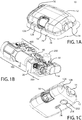
- FIGS. 1A-1C show an exemplary drug delivery device. The drug delivery device may be utilized to administer delivery of a drug treatment into a body of a user.
- the drug pump 10 includes a pump housing 12.
- Pump housing 12 may include one or more housing subcomponents which are fixedly engageable to facilitate easier manufacturing, assembly, and operation of the drug pump.
- drug pump 10 includes a pump housing 12 which includes an upper housing 12A and a lower housing 12B.
- the drug pump may further include an activation mechanism 14, a status indicator 16, and a window 18.
- Window 18 may be any translucent or transmissive surface through which the operation of the drug pump may be viewed.
- the drug pump further includes assembly platform 20, sterile fluid conduit 30, drive mechanism 100 having drug container 50, insertion mechanism 200, fluid pathway connection 300, and power and control system 400.
- One or more of the components of such drug pumps may be modular in that they may be, for example, pre-assembled as separate components and configured into position onto the assembly platform 20 of the drug pump 10 during manufacturing.
- the pump housing 12 contains all of the device components and provides a means of removably attaching the device 10 to the skin of the user.
- the pump housing 12 also provides protection to the interior components of the device 10 against environmental influences.
- the pump housing 12 is ergonomically and aesthetically designed in size, shape, and related features to facilitate easy packaging, storage, handling, and use by users who may be untrained and/or physically impaired.
- the external surface of the pump housing 12 may be utilized to provide product labeling, safety instructions, and the like.
- housing 12 may include certain components, such as status indicator 16 and window 18, which may provide operation feedback to the user.
- the drug pump 10 provides an activation mechanism 14 that is displaced by the user to trigger the start command to the power and control system 400.
- the activation mechanism is a start button 14 that is located through the pump housing 12, such as through an aperture between upper housing 12A and lower housing 12B, and which contacts a control arm 40 of the power and control system 400.
- the start button 14 may be a push button, and in other arrangements, may be an on/off switch, a toggle, or any similar activation feature known in the art.
- the pump housing 12 also provides a status indicator 16 and a window 18.
- one or more of the activation mechanism 14, the status indicator 16, the window 18, and combinations thereof may be provided on the upper housing 12A or the lower housing 12B such as, for example, on a side visible to the user when the drug pump 10 is placed on the body of the user.
- Housing 12 is described in further detail hereinafter with reference to other components.
- the drug pump is configured such that, upon activation by a user by depression of the activation mechanism, the drug pump is initiated to: insert a fluid pathway into the user; enable, connect, or open necessary connections between a drug container, a fluid pathway, and a sterile fluid conduit; and force drug fluid stored in the drug container through the fluid pathway and fluid conduit for delivery into a user.
- One or more optional safety mechanisms may be utilized, for example, to prevent premature activation of the drug pump.
- an optional on-body sensor 24 shown in FIG. 1C ) may be provided as a safety feature to ensure that the power and control system 400, or the activation mechanism, cannot be engaged unless the drug pump 10 is in contact with the body of the user.
- the on-body sensor 24 is located on the bottom of lower housing 12B where it may come in contact with the user's body. Upon displacement of the on-body sensor 24, depression of the activation mechanism is permitted. Accordingly, in one example the on-body sensor 24 is a mechanical safety mechanism, such as for example a mechanical lock out, that prevents triggering of the drug pump 10 by the activation mechanism 14. In another example, the on-body sensor may be an electro-mechanical sensor such as a mechanical lock out that sends a signal to the power and control system 400 to permit activation. In still other examples, the on-body sensor can be electrically based such as, for example, a capacitive- or impedance-based sensor which must detect tissue before permitting activation of the power and control system 400.
- the drug pump 10 utilizes one or more mechanical on-body sensors. Additional integrated safety mechanisms are described herein with reference to other components of the drug pumps.
- the power and control system 400 includes a power source, which provides the energy for various electrical components within the drug pump, one or more feedback mechanisms, a microcontroller, a circuit board, one or more conductive pads, and one or more interconnects. Other components commonly used in such electrical systems may also be included, as would be appreciated by one having ordinary skill in the art.
- the one or more feedback mechanisms may include, for example, audible alarms such as piezo alarms and/or light indicators such as light emitting diodes (LEDs).
- the microcontroller may be, for example, a microprocessor.
- the power and control system 400 controls several device interactions with the user and interfaces with the drive mechanism 100.
- the power and control system 400 interfaces with the control arm 40 to identify when the on-body sensor 24 and/or the activation mechanism 14 have been activated.
- the power and control system 400 may also interface with the status indicator 16 of the pump housing 12, which may be a transmissive or translucent material which permits light transfer, to provide visual feedback to the user.
- the power and control system 400 interfaces with the drive mechanism 100 through one or more interconnects to relay status indication, such as activation, drug delivery, and end-of-dose, to the user.
- status indication may be presented to the user via auditory tones, such as through the audible alarms, and/or via visual indicators, such as through the LEDs.
- control interfaces between the power and control system and the other components of the drug pump are not engaged or connected until activation by the user. This is a desirable safety feature that prevents accidental operation of the drug pump and may additionally maintain the energy contained in the power source during storage, transportation, and the like.
- the power and control system 400 may be configured to provide a number of different status indicators to the user.
- the power and control system 400 may be configured such that after the on-body sensor and/or trigger mechanism have been pressed, the power and control system 400 provides a ready-to-start status signal via the status indicator 16 if device start-up checks provide no errors.
- the power and control system 400 After providing the ready-to-start status signal and, in an arrangement with the optional on-body sensor, if the on-body sensor remains in contact with the body of the user, the power and control system 400 will power the drive mechanism 100 to begin delivery of the drug treatment through the fluid pathway connection 300 and sterile fluid conduit 30.
- the insertion mechanism 200 and the fluid pathway connection 300 may be caused to activate directly by user operation of the activation mechanism 14.
- the power and control system 400 is configured to provide a dispensing status signal via the status indicator 16. After the drug has been administered into the body of the user and after the end of any additional dwell time, to ensure that substantially the entire dose has been delivered to the user, the power and control system 400 may provide an okay-to-remove status signal via the status indicator 16. This may be independently verified by the user by viewing the drive mechanism and drug dose delivery through the window 18 of the pump housing 12. Additionally, the power and control system 400 may be configured to provide one or more alert signals via the status indicator 16, such as for example alerts indicative of fault or operation failure situations.
- activation delays may be utilized during drug delivery.
- one such delay optionally included within the system configuration is a dwell time which ensures that substantially the entire drug dose has been delivered before signaling completion to the user.
- activation of the device may require a delayed depression (i.e., pushing) of the activation mechanism 14 of the drug pump 10 prior to drug pump activation.
- the system may include a feature which permits the user to respond to the end-of-dose signals and to deactivate or power-down the drug pump. Such a feature may similarly require a delayed depression of the activation mechanism, to prevent accidental deactivation of the device.
- Such features provide desirable safety integration and ease-of-use parameters to the drug pumps.
- An additional safety feature may be integrated into the activation mechanism to prevent partial depression and, therefore, partial activation of the drug pumps.
- the activation mechanism and/or power and control system may be configured such that the device is either completely off or completely on, to prevent partial activation.
- the fluid pathway connection 300 includes a sterile fluid conduit 30, a piercing member, a connection hub, and a sterile sleeve.
- the fluid pathway connection may further include one or more flow restrictors.
- the fluid pathway connection 300 is enabled to connect the sterile fluid conduit 30 to the drug container of the drive mechanism 100.
- Such connection may be facilitated by a piercing member, such as a needle, penetrating a pierceable seal of the drug container of the drive mechanism 100.
- the sterility of this connection may be maintained by performing the connection within a flexible sterile sleeve.
- the fluid pathway between drug container and insertion mechanism is complete to permit drug delivery into the body of the user.
- the piercing member of the fluid pathway connection is caused to penetrate the pierceable seal of the drug container of the drive mechanism by direct action of the user, such as by depression of the activation mechanism by the user.
- the activation mechanism itself may bear on the fluid pathway connection such that displacement of the activation mechanism from its original position also causes displacement of the fluid pathway connection.
- this connection is enabled by the user depressing the activation mechanism and, thereby, driving the piercing member through the pierceable seal, because this prevents fluid flow from the drug container until desired by the user.
- a compressible sterile sleeve may be fixedly attached between the cap of the drug container and the connection hub of the fluid pathway connection.
- the piercing member may reside within the sterile sleeve until a connection between the fluid connection pathway and the drug container is desired.
- the sterile sleeve may be sterilized to ensure the sterility of the piercing member and the fluid pathway prior to activation.
- the insertion mechanism 200 includes an insertion mechanism housing having one or more lockout windows, and a base for connection to the assembly platform and/or pump housing (as shown in FIG. 1B and FIG. 1C ).
- the connection of the base to the assembly platform 20 may be, for example, such that the bottom of the base is permitted to pass-through a hole in the assembly platform to permit direct contact of the base to the body of the user.
- the bottom of the base may include a sealing membrane that is removable prior to use of the drug pump 10.
- the insertion mechanism may further include one or more insertion biasing members, a needle, a retraction biasing member, a cannula, and a manifold.
- the manifold may connect to sterile fluid conduit 30 to permit fluid flow through the manifold, cannula, and into the body of the user during drug delivery.
- the insertion mechanism is initially locked into a ready-to use-stage by lockout pin(s) which are initially positioned within lockout windows of the insertion mechanism housing.
- lockout pin(s) which are initially positioned within lockout windows of the insertion mechanism housing.
- insertion biasing member and retraction biasing member are each retained in their compressed, energized states.
- the lockout pin(s) 208 may be directly displaced by user depression of the activation mechanism 14.
- the activation mechanism 14 may be depressed to initiate the drug pump.
- flex prongs 140A may be caused to flex outwards (i.e., in the direction of the hollow arrows) by the decompression force of drive biasing member 122. Such flexion of the flex prongs 140A may permit status switch interconnect 132 to contact electrical contact 134, completing a circuit or otherwise permitting a transmission to the power and control system to provide feedback to the user.
- one or more delivery compliance mechanisms may be utilized to ensure that the status switch interconnect 132 has contacted electrical contact 134 and/or that substantially the entire drug dose has been delivered.
- the drive mechanisms integrate status indication into the drug dose delivery.
- true and accurate end-of-dose indication may be provided to the user.
- the status of the drive mechanism before, during, and after operation can be relayed to the power and control system to provide feedback to the user.
- Such feedback may be tactile, visual, and/or auditory, as described above, and may be redundant such that more than one signal or types of feedback are provided to the user during use of the device.
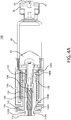
- One or more switch status interconnects 132 may be mounted to a proximal end of drive housing 130.
- a contact sleeve 140 having one or more sleeve hooks 140B at a distal end and a ring 140C at a proximal end having an electrical contact 134 thereon, may be mounted to the drive housing 130 through an axial pass-through from the proximal end of the drive housing 130.
- a drive biasing member 122 may be inserted into a distal end of the drive housing 130.
- a cover sleeve 120 may be inserted into a distal end of the drive housing 130 to substantially cover biasing member 122.
- a piston may be inserted into the distal end of the drive housing 130 and through an axial pass-through of contact sleeve 140, such that a contact protrusion 110B of piston 110 is proximal to the sleeve hooks 140B of contact sleeve 140.
- the piston 110 and drive biasing member 122, and optional cover sleeve 120, may be compressed into drive housing 130.
- Such assembly positions the drive biasing member 122 in an initial compressed, energized state and preferably places a piston interface surface 110C in contact with the proximal surface of the plunger seal 60 within the proximal end of barrel 58.
- piston extension 102 When a piston extension 102 is employed, the piston extension 102 and piston extension biasing member 106, and optional piston biasing member support, may be compressed into an axial pass-through of piston 110.
- the piston, piston biasing member, contact sleeve, and optional components, may be compressed and locked into the ready-to-actuate state within the drive housing 130 prior to attachment or mounting of the drug container 50.
- such components may be mounted, connected, printed, or otherwise attached to their corresponding components prior to assembly of such components into the drive mechanism 100.
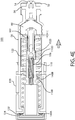
- the stem interconnect 652 may be mounted, affixed, printed, or otherwise attached to incremental status stem 650.
- the incremental status stem 650 and stem interconnect 652 may be mounted to the proximal end of the contact sleeve 640 and/or the proximal end of the drive housing 630 in a manner such that the incremental status stem 650 resides within an axial pass-through of contact sleeve 640 and drive housing 630.
- the incremental status stem 650 is further mounted to reside within an axial pass-through of piston 610.
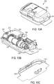
- housing 2012 insertion mechanism 2200, fluid pathway connection 2300, and power and control system 2400, as well as the activation mechanism 2014 are not discussed in detail, those of skill in the art will appreciate that they may be the same or similar to the components and systems discussed in detail with regard to the other arrangements disclosed herein.
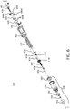
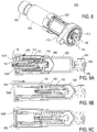
- the portion of the fluid pathway connection 2300 illustrated in FIGS. 11-13C includes a connection mount 2054, a sterile boot 2310, and a piercing assembly 2320.
- the piercing assembly 2320 includes a piercing member 2322 extending from a hub 2324 which supports the piercing member 2322, and provides a fluid connection 2326 (see FIG. 11 ) to which the fluid conduit 2030 or other fluid connector may be fluidly coupled to fluidly couple the drug container 2050 to the insertion mechanism 2200.
- the connection mount 2054 is disposed adjacent the pierceable seal 2056 and includes an aperture adapted to guide the insertion of the piercing member 2322 of the fluid pathway connection into the pierceable seal 2056 of the drug container 2050.
- an arm 2015 coupled to the activation mechanism 2014 exerts an axial force on the piercing assembly 2320 to move the piercing member 2322 axially to pierce the pierceable seal 2056.
- the drive mechanism 2100 is adapted for use in cooperation with the proximal end of the drug container 2050 to axially advance the plunger seal 2060 within the barrel 2058 to dispense the drug treatment through the fluid pathway connection 2300 once the pierceable seal 2056 has been pierced by the piercing member 2322.
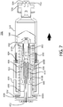
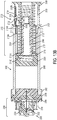
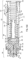
- the drive mechanism 2100 includes a drive housing 2130 having an axis that is coincident with the axis A of the drive mechanism 2100 (see FIG. 11 ).
- the axis A may be disposed in coincident with axes in the container 2050 and the plunger seal 2060.
- a piston 2110 is at least partially disposed within the drive housing 2130 for longitudinal movement along the axis of the drive mechanism 2100. It will be appreciated that the term "axis" when used in connection with the drive housing 2130 is not intended to require the axis to be in a central location of the drive housing 2130 or that the drive housing 2130 be round.
- 10A-14B is adapted to exert a dispensing force on the plunger seal 2060 of the drug container 2050 and to translate outward from a distal end of a housing 2012 to advance the plunger seal 2060 within the drug container 2050 to dispense the drug. While the initial position shown in FIG. 13A illustrates the interface surface 2110C of the piston 2110 as disposed substantially adjacent the distal end of the housing 2012, it will be appreciated that, in alternate embodiments, the piston may be initially disposed in a position extending outside of the drive housing 2130. In such an arrangement, in initial assembly of the drive mechanism 2100 with a drug container 2050, the piston 2110 may be initially at least partially disposed within proximal end of the drug container 2050.
- the drive mechanism 2100 further includes a plurality of piston biasing members 2106, 2122 disposed to move from an energized first position when the piston 2110 is in the retracted first position to a deenergized second position when the piston 2110 is in an extended second position.
- the term "deenergized second position" is a relative term.
- piston biasing members 2106, 2122 in the "deenergized second position” have less energy than the piston biasing members 2106, 2122 in the "energized first position.” That is not to say, however, that the piston biasing members 2106, 2122 in the "deenergized second position” are necessarily completely deenergized or storing no energy.
- biasing members when used in connection with biasing members, be it a specific embodiment of biasing members, such as springs, or the general use of the term “biasing members,” the terms “series” and “parallel” are to be interpreted as they would by those of skill in the art. That is, the terms “series,” “in series,” or “disposed in series” are to be interpreted as springs disposed and operating as they would when connected end to end, and the terms “parallel,” “in parallel,” or “disposed in parallel” are to be interpreted as springs disposed and operating as they would in a side-by-side relationship.
- an additional biasing member may be provided and disposed in series with one or more of the parallelly disposed biasing members.
- an additional biasing member may be provided to engage the piston extension.
- the second sleeve 2126 is slidably coupled to the first sleeve 2124, the first sleeve 2124 sliding distally outward from the second sleeve 2126.
- a coupling structure is provided in order to permit the second sleeve 2126 to travel with the first sleeve 2124 when the first sleeve 2124 is fully extended from the second sleeve 2126.
- the sleeves 2124, 2126 include respective flanges 2124B, 2126A that engage as the proximal end of the first sleeve 2124 approaches the distal end of the second sleeve 2126 (see FIG. 13A ) to cause the second sleeve 2126 to likewise move in an axial direction with the piston 2110 (see FIG. 13C ).
- first sleeve 2124 could alternatively be integrally formed with the piston 2110. In this way, the first sleeve 2124 formed with the piston 2110 would telescope outward from a second sleeve 2126 in a manner similar to that described above.
- sleeve assembly 2120 has been described as including a pair of telescoping sleeves, alternate numbers of sleeves may be used, such as three or more telescoping sleeves. The number of sleeves may be dependent upon the cooperative structures, however, such as the relative dimensions of the drive housing 2130, and the travel of the piston 2110.
- three or more telescoping sleeves may be desirable.
- the springs in a compressed, energized state may have a length equal to the untelescoped sleeves 2124, 2126, yet have an uncompressed, deenergized length that is equal to the length of the telescoped sleeves.
- the switch interconnect 2132 includes a sensor 2134 and an electronic coupling 2136 to the power and control system 2400. At least a portion of the sensor 2134 is disposed adjacent the window 2131, and is adapted to identify a change in the presence of the contact sleeve assembly 2120 proximal to the window 2131 within the drive housing 2130. For example, in the illustrated embodiment, the sensor 2134 may read that the sleeve assembly 2120 is no longer present proximal to the window 2131.
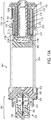
- FIGS. 13A-13B portions of the sleeve assembly 2120 are broken away in FIGS. 13A-13B ; in FIGS. 14A-14B , the housing 2130, sleeve 2126, biasing members 2106, 2122, and end-of-dose indicator 2133 are shown in cross-section taken along line 14-14 in FIG. 11 .
- the sleeve assembly 2120 is disposed adjacent the window 2131 when the piston 2110 is in the retracted first position (see FIG. 13A ), and as the sleeve assembly 2120 begins to telescope outward with the piston 2110 (see FIGS.
- the sleeve assembly 2120 is not disposed adjacent the window 2131 when the piston 2110 is in a fully extended second position (see FIGS. 13C and 14B ).
- the switch interconnect 2132 identifies that the sleeve assembly has passed the window 2131 , and that the end of dose has occurred, and provides that information to the power and control system 2400.
- the electronic coupling 2136 may be of any appropriate design. In the illustrated embodiment, for example, the sensor 2134 connects directly to a PCB board 2138.
- the switch interconnect 2132 illustrated includes a mechanical sensor 2134 in the form of a pivotably mounted trigger 2135, in essence, an on/off mechanical switch.
- the trigger 2135 is disposed in a first position in contact with the sleeve assembly 2120 when the piston 2110 is in a retracted first position.
- the trigger 2135 slides along the telescoping sleeve assembly 2120 until such time as the proximal end 2126B of the second sleeve 2126 passes the window 2131, that is, the trigger 2135.
- the trigger 2135 moves to a second position.
- the movement of the trigger 2135 to the second position results in the electronic coupling 2135 providing a signal indicating the end of dose to the power and control system 2400.
- the sensor may be configured to additionally or alternatively identify at least one of when the sleeve assembly is disposed subjacent the window and when the sleeve assembly is not disposed subjacent the window, the relative motion of the sleeve assembly with reference to the window or another reference component, the stoppage of such motion, and the rate or change of rate of motion.
- any appropriate arrangement may be provided to read the relative position of any appropriate component, the end-of-dose indicator providing a signal to the power and control system to indicate that all of the drug has been administered.
- the switch interconnects and corresponding contacts and/or reference component may be utilized to provide incremental status indication in addition to an end-of-dose indication. For example, in the switch interconnect arrangement described above with reference to FIGS.
- the switch interconnect 2132 may be an electromechanical sensor configured to recognize a number of bumps, ridges, or grooves, in the corresponding sleeve 2126 or any other reference component, the contact with which permits the switch interconnect to signal an incremental status indication (e.g., delivery initiation, amount of volume delivered, duration of plunger travel, etc.) and a final end-of-dose indication. As described herein, similar incremental status indication may be provided in this configuration by utilizing a different type of sensor arrangement.
- the switch interconnect 2132 may be an optical sensor configured to recognize a number of markings on the corresponding sleeve 2126 or any other reference component.
- the embodiments of the present invention provide the necessary drive force to push a plunger seal and a drug fluid within a drug container, while reducing or minimizing the drive mechanism and overall device footprint. Accordingly, the present invention provides a drive mechanism which may be utilized within a more compact drug delivery pump device. The embodiments of the present invention may similarly be utilized to provide additional force, as may be needed for highly viscous drug fluids or for larger volume drug containers.
- the drive mechanism may further include one or more contact surfaces located on corresponding components.
- Such contact surfaces may be electrical contact surfaces, mechanical contact surfaces, or electro-mechanical contact surfaces. Such surfaces may initially be in contact and caused to disengage, or initially be disconnected and caused to engage, to permit a signal to be sent to and/or from the power control system 2400.
- the adhesive surface of the adhesive patch 26 may initially be covered by a non-adhesive patch liner 28, which is removed from the adhesive patch 26 prior to placement of the drug pump 10 in contact with the body of the user. Removal of the patch liner 28 may further remove the sealing membrane 254 of the insertion mechanism 200, opening the insertion mechanism to the body of the user for drug delivery (as shown in FIG. 1C ).
- one or more of the components of drive mechanism 100 and drug pump 10 may be modified.
- the housing of drug pump 10 is shown as two separate components upper housing 12A and lower housing 12B, these components may be a single unified component.
- electrical contact 134 is shown as a separate component from contact sleeve 140, it may be a unified component printed onto the ring surface of the contact sleeve 140.
- a glue, adhesive, or other known materials or methods may be utilized to affix one or more components of the drive mechanism and/or drug pump to each other.
- one or more components of the drive mechanism and/or drug pump may be a unified component.
- the upper housing and lower housing may be separate components affixed together by a glue or adhesive, a screw fit connection, an interference fit, fusion joining, welding, ultrasonic welding, and the like; or the upper housing and lower housing may be a single unified component.
- a glue or adhesive e.g., glue or adhesive
- a screw fit connection e.g., a screw fit connection
- an interference fit e.g., an interference fit
- fusion joining e.g., welding, ultrasonic welding, and the like
- welding ultrasonic welding
- the upper housing and lower housing may be a single unified component.
- the drive mechanisms and drug pumps disclosed herein provide an efficient and easily-operated system for automated drug delivery from a drug container.
- the novel embodiments described herein provide integrated status indication to provide feedback to the user.
- the novel drive mechanisms of the present invention may be directly or indirectly activated by the user.
- the lockout pin(s) which maintain the drive mechanism in its locked, energized state are directly displaced from the corresponding lockout grooves of the piston by user depression of the activation mechanism.
- the configurations of the drive mechanism and drug pumps maintain the sterility of the fluid pathway during storage, transportation, and through operation of the device.
- Such components include the drug container of the drive mechanism, the fluid pathway connection, the sterile fluid conduit, and the insertion mechanism.
- the power and control system, the assembly platform, the control arm, the activation mechanism, the housing, and other components of the drug pump do not need to be sterilized. This greatly improves the manufacturability of the device and reduces associated assembly costs. Accordingly, the devices do not require terminal sterilization upon completion of assembly.
- the components described herein are designed to be modular such that, for example, housing and other components of the pump drug may readily be configured to accept and operate drive mechanism 100, drive mechanism 500, or a number of other variations of the drive mechanism described herein.
- a method of operating the drug pump includes the steps of: activating, by a user, the activation mechanism; displacing a control arm to actuate an insertion mechanism; and actuating a power and control system to activate a drive control mechanism to drive fluid drug flow through the drug pump.
- the method may further include the step of: engaging an optional on-body sensor prior to activating the activation mechanism.
- the method similarly may include the step of: establishing a connection between a fluid pathway connection to a drug container.
- the method of operation may include translating a plunger seal within the drive control mechanism and drug container to force fluid drug flow through the drug container, the fluid pathway connection, a sterile fluid conduit, and the insertion mechanism for delivery of the fluid drug to the body of a user.
- the method of operation of the insertion mechanism and the drug pump may be better appreciated with reference to FIGS. 4A-4E , as described above.
Description
- THIS INVENTION relates to drug delivery pumps. More particularly, this invention relates to drive mechanisms with integrated status indication and drug delivery pumps with status integrated drive mechanisms. Methods of operating such devices, and the methods of assembling such devices are also described.
- Parenteral delivery of various drugs, i.e., delivery by means other than through the digestive track, has become a desired method of drug delivery for a number of reasons. This form of drug delivery by injection may enhance the effect of the substance being delivered and ensure that the unaltered medicine reaches its intended site at a significant concentration. Similarly, undesired side effects associated with other routes of delivery, such as systemic toxicity, can potentially be avoided through parenteral delivery. By bypassing the digestive system of a mammalian patient, one can avoid degradation of the active ingredients caused by the catalytic enzymes in the digestive tract and liver and ensure that a necessary amount of drug, at a desired concentration, reaches the targeted site.
- Traditionally, manually operated syringes and injection pens have been employed for delivering parenteral drugs to a patient. More recently, parenteral delivery of liquid medicines into the body has been accomplished by administering bolus injections using a needle and reservoir, continuously by gravity driven dispensers, or via transdermal patch technologies. Bolus injections often imperfectly match the clinical needs of the patient, and usually require larger individual doses than are desired at the specific time they are given. Continuous delivery of medicine through gravity-feed systems compromises the patient's mobility and lifestyle, and limits the therapy to simplistic flow rates and profiles. Another form of drug delivery, transdermal patches, similarly has its restrictions. Transdermal patches often require specific molecular drug structures for efficacy, and the control of the drug administration through a transdermal patch is severely limited.
- Ambulatory infusion pumps have been developed for delivering liquid medicaments to a patient. These infusion devices have the ability to offer sophisticated fluid delivery profiles accomplishing bolus requirements, continuous infusion and variable flow rate delivery. These infusion capabilities usually result in better efficacy of the drug and therapy and less toxicity to the patient's system. Currently available ambulatory infusion devices are expensive, difficult to program and prepare for infusion, and tend to be bulky, heavy and very fragile. Filling these devices can be difficult and require the patient to carry both the intended medication as well as filling accessories. The devices often require specialized care, maintenance, and cleaning to assure proper functionality and safety for their intended long-term use, and are not cost-effective for patients or healthcare providers.
- As compared to syringes and injection pens, pump type delivery devices can be significantly more convenient to a patient, in that doses of the drug may be calculated and delivered automatically to a patient at any time during the day or night. Furthermore, when used in conjunction with metabolic sensors or monitors, pumps may be automatically controlled to provide appropriate doses of a fluidic medium at appropriate times of need, based on sensed or monitored metabolic levels. As a result, pump type delivery devices have become an important aspect of modern medical treatments of various types of medical conditions, such as diabetes, and the like.
- For example, in
WO 2011/046950 there is described a fluid delivery device comprising a housing having a fluid reservoir. A needle is in fluid communication with the fluid reservoir in an engaged position and out of fluid communication with the fluid reservoir in armed and storage positions. A proximal end of a biasing member is coupled to the housing and a distal end of the biasing member is configured to deliver a force to the fluid reservoir. A piston member extends through the biasing member and is coupled to the distal end of the biasing member. The piston member is fixed with respect to the housing in a locked position such that the biasing member does not deliver the force to the fluid reservoir and moveable with respect to the housing in a released position such that the biasing member delivers the force to the fluid reservoir. Transitioning the needle from the storage position to the armed position transitions the piston from the locked position to the released position. - In
WO 2010/112377 there is described a medicament delivery device comprising a housing for holding a medicament cartridge, a drive and a drive control means. The medicament cartridge has a medicament outlet and a bung able to be driven via a piston rod driven by the drive force of the drive and controlled by the drive control means. Additionally, the medicament delivery device comprises a restraining means for applying a restraining force to the piston rod, in a direction opposite to the drive force. By varying the restraining force by the drive control means the movement of the bung along the medicament cartridge can be controlled. - In
WO 2013/033467 , which comprises part of the state of the art by virtue of A.54(3) EPC, there is described a drive mechanism having integrated status indication. The drive mechanism includes a drive housing, a status switch interconnect, a drive biasing member, a piston, and a drug container having a cap, a pierceable seal, a barrel, and a plunger seal, wherein the drive biasing member is configured to bear upon an interface surface of the piston. The drive mechanism may include an incremental status stem having a stem interconnect, wherein the stem resides within the drive housing and the piston, and wherein the stem has an interconnect which engages one or more contacts on the piston to provide incremental feedback. A drug delivery pump with integrated status indication is also disclosed and includes a housing and an assembly platform, upon which an activation mechanism, an insertion mechanism, a fluid pathway connection, a power and control system, and the drive mechanism having a drug container may be mounted. - While pump type delivery systems have been utilized to solve a number of patient needs, manually operated syringes and injection pens often remain a preferred choice for drug delivery as they now provide integrated safety features and can easily be read to identify the status of drug delivery and the end of dose dispensing. However, manually operated syringes and injections pens are not universally applicable and are not preferred for delivery of all drugs. There remains a need for an adjustable (and/or programmable) infusion system that is precise and reliable and can offer clinicians and patients a small, low cost, light weight, simple to use alternative for parenteral delivery of liquid medicines.
- The present invention provides drive mechanisms with integrated status indication and drug delivery pumps which incorporate such drive mechanisms. Methods of operating such devices, and methods of assembling such devices are also described. The drive mechanisms of the present invention provide integrated status indication features which provide feedback to the user before, during, and after drug delivery. For example, the user may be provided with an initial feedback to identify that the system is operational and ready for drug delivery. Upon activation, the system may then provide one or more drug delivery status indications to the user. At completion of drug delivery, the drive mechanism and drug pump may provide an end-of-dose indication. As the end-of-dose indication is tied to the piston reaching the end of its axial translation, the drive mechanism and drug pump provide a true end-of-dose indication to the user. Additionally, embodiments of the present invention provide end-of-dose compliance to ensure that substantially the entire drug dose has been delivered to the user and that the status indication features have been properly contacted to provide accurate feedback to the user. Through these mechanisms, confirmation of drug dose delivery can accurately be provided to the user or administrator. Accordingly, the novel devices of the present invention alleviate one or more of the problems associated with prior art devices, such as those referred to above.
- According to the present invention there is provided a drug pump drive mechanism having the features of claim 1.
- In a first embodiment, the present invention provides a drive mechanism having integrated status indication which includes: a drive housing, a status switch interconnect, a drive biasing member, a piston, and a drug container having a cap, a pierceable seal, a barrel, and a plunger seal. The drive biasing member may be configured to bear upon an interface surface of the piston. The drug container may preferably contain a drug fluid for delivery to the user. The drive mechanism may further include a connection mount attached to the pierceable seal. A cover sleeve may be utilized between the drive biasing member and the interface surface of the piston to, for example, provide more even distribution of force from the biasing member to the piston. A contact sleeve may be slidably mounted to the drive housing through an axial aperture of the drive housing, such that sleeve hooks at a distal end of the contact sleeve are caused to contact the piston between the interface surface and a contact protrusion near
the proximal end of the piston. The piston may also include a locking groove, between the contact protrusion and the proximal end of the piston. The contact sleeve may have a radially extending ring at its proximal end, upon which reside one or more flex prongs. - The drive mechanism may further include one or more contact surfaces located on corresponding components. Such contact surfaces may be electrical contact surfaces, mechanical contact surfaces, or electro-mechanical contact surfaces. Such surfaces may initially be in contact and caused to disengage, or initially be disconnected and caused to engage, to permit a signal to be sent to and/or from the power control system. In at least one embodiment, the contact surfaces may be electrical contact surfaces which are initially disconnected and caused to come into engagement whereby, upon such engagement, the contact surfaces are capable of continuing an energy pathway or otherwise relaying a signal to the power and control system. In another embodiment of the present invention, the contact surfaces are mechanical contact surfaces which are initially in contact and caused to disengage whereby, upon such disengagement, such disengagement is communicated to the power and control system. Such signals may be transferred across one or more interconnects to the power and control system or by mechanical action to the power and control system. Such components may be utilized within the drive mechanism to measure and relay information related to the status of operation of the drive mechanism, which may be converted by the power and control system into tactile, auditory, and/or visual feedback to the user. Regardless of the electrical or mechanical nature of the contact surfaces, the motion of the components which permits transmission of a signal to the power control system is enabled by a biasing member axially translating a contact sleeve in the distal direction during operation of the device.
- The drive mechanism may include a piston extension slidably mounted at a distal end and within an axial pass-through of piston; a piston extension biasing member, which is mounted within the axial pass-through of piston and initially compressed between the piston extension and piston; and, optionally, a piston biasing member support between the piston extension biasing member and piston extension. The piston extension is retained within the piston by interaction between one or more extension arms of the piston extension and one or more corresponding connection slots of the piston. The piston extension may be utilized to perform a compliance push of drug fluid from the drug container. Additionally or alternatively, the drive mechanism may utilize a
compressible plunger seal, wherein such compression capacity or distance permits a compliance push of drug fluid from the drug container. Other compliance features are described further herein. - In another embodiment of the present invention, a drive mechanism having integrated incremental status indication includes a drive housing, a drive biasing member, a piston, an incremental status stem having a stem interconnect mounted, affixed, printed, or otherwise attached thereon, and a drug container having a cap, a pierceable seal, a barrel, and a plunger seal, wherein the incremental status stem resides within axial pass-throughs of the drive housing and the piston. The incremental status stem may have one or more interconnects which contact one or more contacts on the piston to provide incremental status feedback to the user. The incremental status embodiment may similarly utilize the electrical, mechanical, or electro-mechanical interconnects and contacts, and/or one or more of the compliance features, described above.
- There is also described a drug delivery pump with integrated status indication. The drug pump includes a housing and an assembly platform, upon which an activation mechanism, an insertion mechanism, a fluid pathway connection, a power and control system, and a drive mechanism having a drug container may be mounted. The drive biasing member may be configured to bear upon an interface surface of the piston. The drug container may preferably contain a drug fluid for delivery to the user. The drive mechanism may further include a connection mount attached to the pierceable seal. A cover sleeve may be utilized between the drive biasing member and the interface surface of the piston to, for example, provide more even distribution of force from the biasing member to the piston. A contact sleeve may be slidably mounted to the drive housing through an axial aperture of the drive housing, such that sleeve hooks at a distal end of the contact sleeve are caused to contact the piston between interface surface and a contact protrusion near the proximal end of the piston. The piston may also include a locking groove, between contact protrusion and the proximal end of the piston. The contact sleeve may have a radially extending ring at its proximal end, upon which reside one or more flex prongs. The drive mechanism may further include one or more contact surfaces located on corresponding components. Such contact surfaces may be electrical contact surfaces, mechanical contact surfaces, or electro-mechanical contact surfaces. Such surfaces may initially be in contact and caused to disengage, or initially be disconnected and caused to engage, to permit a signal to be sent to and/or from the power control system. In one example the contact surfaces may be electrical contact surfaces which are initially disconnected and caused to come into engagement whereby, upon such engagement, the contact surfaces are capable of continuing an energy pathway or otherwise relaying a signal to the power and control system. In another example, the contact surfaces are mechanical contact surfaces which are initially in contact and caused to disengage whereby, upon such disengagement, such disengagement is communicated to the power and control system. Regardless of the electrical or mechanical nature of the contact surfaces, the motion of the components which permits transmission of a signal to the power control system is enabled by a biasing member axially translating a contact sleeve in the distal direction during operation of the device.
- In another drug delivery pump with incremental status indication, the drug pump includes a housing and an assembly platform, upon which an activation mechanism, an insertion mechanism, a fluid pathway connection, a power and control system, and a drive mechanism having a drug container may be mounted. The drug pump further includes an incremental status stem having a stem interconnect mounted, affixed, printed, or otherwise attached thereon, wherein the incremental status stem resides within axial pass-throughs of the drive housing and the piston, and wherein the incremental status stem has one or more interconnects which contact one or more contacts on the piston to complete a transmission to the power and control system to provide incremental feedback to the user. The drug delivery pump with incremental status indication may similarly utilize the electrical, mechanical, or electro-mechanical interconnects and contacts, and/or one or more of the compliance features, described above.
- There is also described a method of assembly. The drug container may first be assembled and filled with a drug fluid. The drug container includes a cap, a pierceable seal, a barrel, and a plunger seal. The pierceable seal may be fixedly engaged between the cap and the barrel, at a distal end of the barrel. The barrel may be filled with a drug fluid through the open proximal end prior to insertion of the plunger seal from the proximal end of the
barrel 58. An optional connection mount may be mounted to a distal end of the pierceable seal. The connection mount serves to guide the insertion of the piercing member of the fluid pathway connection into the barrel of the drug container. The drug container may then be mounted to a distal end of drive housing. - Prior to mounting the drug container to the housing, a switch status interconnect may be mounted to a proximal end of drive housing. A contact sleeve, having one or more sleeve hooks at a distal end and a ring at a proximal end having an electrical contact thereon, may be mounted to the drive housing through an axial pass-through from the proximal end of the drive housing. A drive biasing member may be inserted into a distal end of the drive housing. Optionally, a cover sleeve may be inserted into a distal end of the drive housing to substantially cover the biasing member. A piston may be inserted into the distal end of the drive housing and through an axial pass-through of the contact sleeve, such that a contact protrusion of the piston is proximal to the sleeve hooks of the contact sleeve. The piston and drive biasing member, and optional cover sleeve, may be compressed into the drive housing. Such assembly positions the drive biasing member in an initial compressed, energized state and preferably places a piston interface surface in contact with the proximal surface of the plunger seal within the proximal end of barrel. When a piston extension is employed, the piston extension and piston extension biasing member, and optional piston biasing member support, may be compressed into an axial pass-through of the piston prior to compression of the components. Prior to, or after, installing these components into the drive mechanism housing, the primary container may be attached.
- When one or more interconnects or contacts are utilized for status indication, such components may be mounted, connected, printed, or otherwise attached to their corresponding components prior to assembly of such components into the drive mechanism. When a separate incremental status stem and a corresponding stem interconnect are utilized for such incremental status indication, the stem interconnect may be mounted, affixed, printed, or otherwise attached to the incremental status stem prior to assembly of the incremental status stem to the proximal end of the contact sleeve and/or the proximal end of the drive housing in a manner such that the incremental status stem resides within an axial pass-through of the contact sleeve and drive housing. The incremental status stem is further mounted to reside within an axial pass-through of the piston.
- The disclosure describes, in one aspect, a drug pump drive mechanism for use in cooperation with a drug container including a plunger seal. The drive mechanism has an axis and includes a drive housing, a piston adapted to impart movement to the plunger seal within the drug container, a plurality of biasing members disposed in parallel, and a retainer. The piston is disposed for movement from a retracted first position along the axis to an extended second position. The biasing members are adapted to move from an energized first position to a deenergized second position as a result of the release of energy. The biasing members are disposed to cause movement of the piston from the retracted first position to the extended second position as the biasing members move from the energized first position to the deenergized second position. The retainer is disposed to maintain the biasing members in the energized first position when the retainer is in a retaining first position, and to release the biasing members from the first energized position when the retainer moves to a releasing second position.
- In at least one embodiment, the plurality of biasing members includes at least one of a tension spring or a compression spring. In at least one embodiment, the plurality of biasing members includes a pair of springs, in at least one embodiment of which the springs are compression springs. In at least one further embodiment, the compression springs are concentrically disposed, and disposed about at least a portion of the piston. In at least one embodiment, the retainer engages at least a portion of the piston to retain the piston in its retracted position when the retainer is in its retaining first position. At least one embodiment further includes a sleeve assembly disposed about at least one of the plurality of biasing members. In at least one embodiment, the sleeve assembly includes a plurality of telescoping sleeves, and the sleeve assembly is disposed to move to axially with the piston. At least one embodiment further includes at least one window and at least a portion of the sleeve assembly is visible through the window with at least a portion of the sleeve assembly being visible through said window until the piston is in the extended second position. At least one embodiment further includes an end-of-dose indicator disposed substantially adjacent the window, the end-of-dose indicator being adapted to identify at least one of when the sleeve assembly is disposed subjacent the window and when the sleeve assembly is not disposed subjacent the window, the relative motion of the sleeve assembly with reference to the window or another reference component, the stoppage of such motion, and the rate or change of rate of motion. In at least one embodiment, the end-of-dose indicator includes a sensor
disposed to sense at least one of when the sleeve assembly is disposed subjacent the window and when the sleeve assembly is not disposed subjacent the window. In at least one embodiment, the sensor is a mechanical sensor, an electrical sensor, an ultrasonic sensor, a capacitive sensor, a magnetic sensor, or an optical sensor. In at least one embodiment, the sensor is a mechanical sensor disposed to bear against the sleeve assembly when the sleeve assembly is disposed subjacent the window. - At least some embodiments of the present invention provide the necessary drive force to push a plunger seal and a drug fluid within a drug container, while reducing or minimizing the drive mechanism and overall device footprint. Accordingly, the present invention may provide a drive mechanism which may be utilized within a more compact drug delivery pump device. Some embodiments of the present invention may similarly be utilized to provide additional force, as may be needed for highly viscous drug fluids or for larger volume drug containers.
- The novel embodiments of the present invention provide drive mechanisms with integrated status indication, which are capable of providing incremental status of the drug delivery before, during, and after operation of the device, and provide means for ensuring drug dose compliance, i.e., ensuring substantially the entire drug dose has been delivered to the user. Throughout this specification, unless otherwise indicated, "comprise," "comprises," and "comprising," or related terms such as "includes" or "consists of," are used inclusively rather than exclusively, so that a stated integer or group of integers may include one or more other non-stated integers or groups of integers. As will be described further below, the embodiments of the present invention may include one or more additional components which may be considered standard components in the industry of medical devices. The components, and the embodiments containing such components, are within the contemplation of the present invention and are to be understood as falling within the breadth and scope of the present invention.
- The following non-limiting embodiments of the invention are described herein with reference to the following drawings, wherein:
-
FIG. 1A shows an isometric view of a drug delivery pump having safety integrated insertion mechanisms; -
FIG. 1B shows an isometric view of the interior components of the drug delivery pump shown inFIG. 1A ; -
FIG. 1C shows an isometric view of the bottom of the drug delivery pump shown inFIG. 1A ; -
FIG. 2 shows an isometric view of a drive mechanism; -
FIG. 3 shows an exploded view, along an axis "A," of the drive mechanism shown inFIG. 2 , -
FIG. 4A shows a cross-sectional view of the drive mechanism shown inFIG. 2 in an initial inactive state; -
FIG. 4B shows a cross-sectional view of the drive mechanism shown inFIG. 2 in an actuated state; -
FIG. 4C shows a cross-sectional view of the drive mechanism shown inFIG. 2 in a further actuated state as drug delivery from the mechanism continues; -
FIG. 4D shows a cross-sectional view of the drive mechanism shown inFIG. 2 as the mechanism nears completion of drug delivery; -
FIG. 4E shows a cross-sectional view of the drive mechanism shown inFIG. 2 as the mechanism performs a compliance push to ensure completion of drug delivery; -
FIG. 5 shows an isometric view of a drive mechanism, according to a second arrangement; -
FIG. 6 shows an exploded view, along an axis "A," of the drive mechanism shown inFIG. 5 ; -
FIG. 7 shows a cross-sectional view of the drive mechanism shown inFIG. 5 in an actuated state; -
FIG. 8 shows an isometric view of a drive mechanism according to a further arrangement; -
FIG. 9A shows a cross-sectional view of the drive mechanism shown inFIG. 8 in an initial inactive state; -
FIG. 9B shows a cross-sectional view of the drive mechanism shown inFIG. 8 in an actuated state and as the mechanism nears completion of drug delivery; -
FIG. 9C shows a cross-sectional view of the drive mechanism shown inFIG. 8 as the mechanism completes drug delivery and triggers an end-of-dose signal. -
FIG. 10A is an isometric view of another drug delivery pump having safety integrated insertion mechanisms; -
FIG. 10B is an isometric view of the interior components of the drug delivery pump shown inFIG. 10A ; -
FIG. 10C is an isometric view of the bottom of the drug delivery pump shown inFIG. 10A ; -
FIG. 11 is an isometric view of a drive mechanism, according to an embodiment of the present invention; -
FIG. 12 is an exploded view, along an axis "A," of the drive mechanism shown inFIG. 11 , -
FIG. 13A is a cross-sectional view of the drive mechanism shown inFIG. 11 in an initial inactive state; -
FIG. 13B is a cross-sectional view of the drive mechanism shown inFIG. 11 in an actuated state; -
FIG. 13C is a cross-sectional view of the drive mechanism shown inFIG. 11 at the completion of drug delivery; -
FIG. 14A is a cross-sectional view of the drive mechanism taken along line 14-14 inFIG. 11 ; and -
FIG. 14B is a cross-sectional view of the drive mechanism similar toFIG. 14A , but after the activation of the sensor. - As used herein to describe the drive mechanisms, drug delivery pumps, or any of the relative positions of the components of the present invention, the terms "axial" or "axially" refer generally to a longitudinal axis "A" around which the drive mechanisms are preferably positioned, although not necessarily symmetrically there-around. The term "radial" refers generally to a direction normal to axis A. The terms "proximal," "rear," "rearward," "back," or "backward" refer generally to an axial direction in the direction "P". The terms "distal," "front," "frontward," "depressed," or "forward" refer generally to an axial direction in the direction "D". As used herein, the term "glass" should be understood to include other similarly non-reactive materials suitable for use in a pharmaceutical grade application that would normally require glass, including but not limited to certain non-reactive polymers such as cyclic olefin copolymers (COC) and cyclic olefin polymers (COP). The term "plastic" may include both thermoplastic and thermosetting polymers. Thermoplastic polymers can be resoftened to their original condition by heat; thermosetting polymers cannot. As used herein, the term "plastic" refers primarily to moldable thermoplastic polymers such as, for example, polyethylene and polypropylene, or an acrylic resin, that also typically contain other ingredients such as curatives, fillers, reinforcing agents, colorants, and/or plasticizers, etc., and that can be formed or molded under heat and pressure. As used herein, the term "plastic" is not meant to include glass, non-reactive polymers, or elastomers that are approved for use in applications where they are in direct contact with therapeutic liquids that can interact with plastic or that can be degraded by substituents that could otherwise enter the liquid from plastic. The term "elastomer," "elastomeric" or "elastomeric material" refers primarily to cross-linked thermosetting rubbery polymers that are more easily deformable than plastics but that are approved for use with pharmaceutical grade fluids and are not readily susceptible to leaching or gas migration under ambient temperature and pressure. "Fluid" refers primarily to liquids, but can also include suspensions of solids dispersed in liquids, and gasses dissolved in or otherwise present together within liquids inside the fluid-containing portions of syringes. According to various aspects and embodiments described herein, reference is made to a "biasing member", such as in the context of one or more biasing members for insertion or retraction of the needle, trocar, and/or cannula. It will be appreciated that the biasing member may be any member that is capable of storing and releasing energy. Non-limiting examples include a spring, such as for example a coiled spring, a compression or extension spring, a torsional spring, and a leaf spring, a resiliently compressible or elastic band, or any other member with similar functions. In at least one embodiment of the present invention, the biasing member is a spring, preferably a compression spring.
- The novel devices of the present invention provide drive mechanisms with integrated status indication and drug delivery pumps which incorporate such drive mechanisms. Such devices are safe and easy to use, and are aesthetically and ergonomically appealing for self-administering patients. The devices described herein incorporate features which make activation, operation, and lock-out of the device simple for even untrained users. The novel devices of the present invention provide these desirable features without any of the problems associated with known prior art devices. Certain non-limiting examples of the drug delivery pumps, drive mechanisms, and their respective components are described further herein with reference to the accompanying figures.
- As used herein, the term "pump" is intended to include any number of drug delivery systems which are capable of dispensing a fluid to a user upon activation. Such drug delivery systems include, for example, injection systems, infusion pumps, bolus injectors, and the like.
FIGS. 1A-1C show an exemplary drug delivery device. The drug delivery device may be utilized to administer delivery of a drug treatment into a body of a user. As shown inFIGS. 1A-1C , thedrug pump 10 includes apump housing 12.Pump housing 12 may include one or more housing subcomponents which are fixedly engageable to facilitate easier manufacturing, assembly, and operation of the drug pump. For example,drug pump 10 includes apump housing 12 which includes anupper housing 12A and alower housing 12B. The drug pump may further include anactivation mechanism 14, astatus indicator 16, and awindow 18.Window 18 may be any translucent or transmissive surface through which the operation of the drug pump may be viewed. As shown inFIG. 1B , the drug pump further includesassembly platform 20, sterilefluid conduit 30,drive mechanism 100 havingdrug container 50,insertion mechanism 200,fluid pathway connection 300, and power andcontrol system 400. One or more of the components of such drug pumps may be modular in that they may be, for example, pre-assembled as separate components and configured into position onto theassembly platform 20 of thedrug pump 10 during manufacturing. - The
pump housing 12 contains all of the device components and provides a means of removably attaching thedevice 10 to the skin of the user. Thepump housing 12 also provides protection to the interior components of thedevice 10 against environmental influences. Thepump housing 12 is ergonomically and aesthetically designed in size, shape, and related features to facilitate easy packaging, storage, handling, and use by users who may be untrained and/or physically impaired. Furthermore, the external surface of thepump housing 12 may be utilized to provide product labeling, safety instructions, and the like. Additionally, as described above,housing 12 may include certain components, such asstatus indicator 16 andwindow 18, which may provide operation feedback to the user. - The
drug pump 10 provides anactivation mechanism 14 that is displaced by the user to trigger the start command to the power andcontrol system 400. In a preferred example, the activation mechanism is astart button 14 that is located through thepump housing 12, such as through an aperture betweenupper housing 12A andlower housing 12B, and which contacts acontrol arm 40 of the power andcontrol system 400. In at least one arrangement, thestart button 14 may be a push button, and in other arrangements, may be an on/off switch, a toggle, or any similar activation feature known in the art. Thepump housing 12 also provides astatus indicator 16 and awindow 18. In other arrangements, one or more of theactivation mechanism 14, thestatus indicator 16, thewindow 18, and combinations thereof may be provided on theupper housing 12A or thelower housing 12B such as, for example, on a side visible to the user when thedrug pump 10 is placed on the body of the user.Housing 12 is described in further detail hereinafter with reference to other components. - The drug pump is configured such that, upon activation by a user by depression of the activation mechanism, the drug pump is initiated to: insert a fluid pathway into the user; enable, connect, or open necessary connections between a drug container, a fluid pathway, and a sterile fluid conduit; and force drug fluid stored in the drug container through the fluid pathway and fluid conduit for delivery into a user. One or more optional safety mechanisms may be utilized, for example, to prevent premature activation of the drug pump. For example, an optional on-body sensor 24 (shown in
FIG. 1C ) may be provided as a safety feature to ensure that the power andcontrol system 400, or the activation mechanism, cannot be engaged unless thedrug pump 10 is in contact with the body of the user. In one such arrangement, the on-body sensor 24 is located on the bottom oflower housing 12B where it may come in contact with the user's body. Upon displacement of the on-body sensor 24, depression of the activation mechanism is permitted. Accordingly, in one example the on-body sensor 24 is a mechanical safety mechanism, such as for example a mechanical lock out, that prevents triggering of thedrug pump 10 by theactivation mechanism 14. In another example, the on-body sensor may be an electro-mechanical sensor such
as a mechanical lock out that sends a signal to the power andcontrol system 400 to permit activation. In still other examples, the on-body sensor can be electrically based such as, for example, a capacitive- or impedance-based sensor which must detect tissue before permitting activation of the power andcontrol system 400. These concepts are not mutually exclusive and one or more combinations may be utilized to prevent, for example, premature activation of the drug pump. In a preferred arrangement, thedrug pump 10 utilizes one or more mechanical on-body sensors. Additional integrated safety mechanisms are described herein with reference to other components of the drug pumps. - The power and
control system 400 includes a power source, which provides the energy for various electrical components within the drug pump, one or more feedback mechanisms, a microcontroller, a circuit board, one or more conductive pads, and one or more interconnects. Other components commonly used in such electrical systems may also be included, as would be appreciated by one having ordinary skill in the art. The one or more feedback mechanisms may include, for example, audible alarms such as piezo alarms and/or light indicators such as light emitting diodes (LEDs). The microcontroller may be, for example, a microprocessor. The power andcontrol system 400 controls several device interactions with the user and interfaces with thedrive mechanism 100. In one arrangement, the power andcontrol system 400 interfaces with thecontrol arm 40 to identify when the on-body sensor 24 and/or theactivation mechanism 14 have been activated. The power andcontrol system 400 may also interface with thestatus indicator 16 of thepump housing 12, which may be a transmissive or translucent material which permits light transfer, to provide visual feedback to the user. The power andcontrol system 400 interfaces with thedrive mechanism 100 through one or more interconnects to relay status indication, such as activation, drug delivery, and end-of-dose, to the user. Such status indication may be presented to the user via auditory tones, such as through the audible alarms, and/or via visual indicators, such as through the LEDs. In a preferred arrangement, the control interfaces between the power and control system and the other components of the drug pump are not engaged or connected until activation by the user. This is a desirable safety feature that prevents accidental operation of the drug pump and may additionally maintain the energy contained in the power source during storage, transportation, and the like. - The power and
control system 400 may be configured to provide a number of different status indicators to the user. For example, the power andcontrol system 400 may be configured such that after the on-body sensor and/or trigger mechanism have been pressed, the power andcontrol system 400 provides a ready-to-start status signal via thestatus indicator 16 if device start-up checks provide no errors. After providing the ready-to-start status signal and, in an arrangement with the optional on-body sensor, if the on-body sensor remains in contact with the body of the user, the power andcontrol system 400 will power thedrive mechanism 100 to begin delivery of the drug treatment through thefluid pathway connection 300 and sterilefluid conduit 30. In a preferred arrangement, theinsertion mechanism 200 and thefluid pathway connection 300 may be caused to activate directly by user operation of theactivation mechanism 14. During the drug delivery process, the power andcontrol system 400 is configured to provide a dispensing status signal via thestatus indicator 16. After the drug has been administered into the body of the user and after the end of any additional dwell time, to ensure that substantially the entire dose has been delivered to the user, the power andcontrol system 400 may provide an okay-to-remove status signal via thestatus indicator 16. This may be independently verified by the user by viewing the drive mechanism and drug dose delivery through thewindow 18 of thepump housing 12. Additionally, the power andcontrol system 400 may be configured to provide one or more alert signals via thestatus indicator 16, such as for example alerts indicative of fault or operation failure situations. - Other power and control system configurations may be utilized with the drug pumps. For example, certain activation delays may be utilized during drug delivery. As mentioned above, one such delay optionally included within the system configuration is a dwell time which ensures that substantially the entire drug dose has been delivered before signaling completion to the user. Similarly, activation of the device may require a delayed depression (i.e., pushing) of the
activation mechanism 14 of thedrug pump 10 prior to drug pump activation. Additionally, the system may include a feature which permits the user to respond to the end-of-dose signals and to deactivate or power-down the drug pump. Such a feature may similarly require a delayed depression of the activation mechanism, to prevent
accidental deactivation of the device. Such features provide desirable safety integration and ease-of-use parameters to the drug pumps. An additional safety feature may be integrated into the activation mechanism to prevent partial depression and, therefore, partial activation of the drug pumps. For example, the activation mechanism and/or power and control system may be configured such that the device is either completely off or completely on, to prevent partial activation. Such features are described in further detail hereinafter with regard to other aspects of the drug pumps. - The
fluid pathway connection 300 includes a sterilefluid conduit 30, a piercing member, a connection hub, and a sterile sleeve. The fluid pathway connection may further include one or more flow restrictors. Upon proper activation of thedevice 10, thefluid pathway connection 300 is enabled to connect the sterilefluid conduit 30 to the drug container of thedrive mechanism 100. Such connection may be facilitated by a piercing member, such as a needle, penetrating a pierceable seal of the drug container of thedrive mechanism 100. The sterility of this connection may be maintained by performing the connection within a flexible sterile sleeve. Upon substantially simultaneous activation of the insertion mechanism, the fluid pathway between drug container and insertion mechanism is complete to permit drug delivery into the body of the user. - In at least one example, the piercing member of the fluid pathway connection is caused to penetrate the pierceable seal of the drug container of the drive mechanism by direct action of the user, such as by depression of the activation mechanism by the user. For example, the activation mechanism itself may bear on the fluid pathway connection such that displacement of the activation mechanism from its original position also causes displacement of the fluid pathway connection. In a preferred arrangement, this connection is enabled by the user depressing the activation mechanism and, thereby, driving the piercing member through the pierceable seal, because this prevents fluid flow from the drug container until desired by the user. In such an arrangement, a compressible sterile sleeve may be fixedly attached between the cap of the drug container and the connection hub of the fluid pathway connection. The piercing member may reside within the sterile sleeve until a connection between the fluid connection pathway and the drug container is desired. The sterile sleeve may be sterilized to ensure the sterility of the piercing member and the fluid pathway prior to activation.
- The drug pump is capable of delivering a range of drugs with different viscosities and volumes. The drug pump is capable of delivering a drug at a controlled flow rate (speed) and/or of a specified volume. In one arrangement, the drug delivery process is controlled by one or more flow restrictors within the fluid pathway connection and/or the sterile fluid conduit. In other arrangements, other flow rates may be provided by varying the geometry of the fluid flow path or delivery conduit, varying the speed at which a component of the drive mechanism advances into the drug container to dispense the drug therein, or combinations thereof. Still further details about the
fluid pathway connection 300 and the sterilefluid conduit 30 are provided hereinafter in later sections in reference to other arrangements. - A number of insertion mechanisms may be utilized within the drug pumps. In at least one example, the
insertion mechanism 200 includes an insertion mechanism housing having one or more lockout windows, and a base for connection to the assembly platform and/or pump housing (as shown inFIG. 1B and FIG. 1C ). The connection of the base to theassembly platform 20 may be, for example, such that the bottom of the base is permitted to pass-through a hole in the assembly platform to permit direct contact of the base to the body of the user. In such configurations, the bottom of the base may include a sealing membrane that is removable prior to use of thedrug pump 10. The insertion mechanism may further include one or more insertion biasing members, a needle, a retraction biasing member, a cannula, and a manifold. The manifold may connect to sterilefluid conduit 30 to permit fluid flow through the manifold, cannula, and into the body of the user during drug delivery. - As used herein, "needle" is intended to refer to a variety of needles including but not limited to conventional hollow needles, such as a rigid hollow steel needles, and solid core needles more commonly referred to as a "trocars." In a preferred arrangement, the needle is a 27 gauge (0.4128mm outer diameter, 0.210 mm inner diameter) solid core trocar and in other arrangements, the needle may be any size needle suitable to insert the cannula for the type of drug and drug administration (e.g., subcutaneous, intramuscular, intradermal, etc.) intended. A
sterile boot may be utilized within the needle insertion mechanism. The sterile boot is a collapsible sterile membrane that is in fixed engagement at a proximal end with the manifold and at a distal end with the base. In at least one example, the sterile boot is maintained in fixed engagement at a distal end between base and insertion mechanism housing. Base includes a base opening through which the needle and cannula may pass-through during operation of the insertion mechanism, as will be described further below. Sterility of the cannula and needle are maintained by their initial positioning within the sterile portions of the insertion mechanism. Specifically, as described above, needle and cannula are maintained in the sterile environment of the manifold and sterile boot. The base opening of base may be closed from non-sterile environments as well, such as by for example a sealing membrane 254 (shown inFIG. 1C ). - In one arrangement, the insertion mechanism is initially locked into a ready-to use-stage by lockout pin(s) which are initially positioned within lockout windows of the insertion mechanism housing. In this initial configuration, insertion biasing member and retraction biasing member are each retained in their compressed, energized states. As shown in
FIG. 1B , the lockout pin(s) 208 may be directly displaced by user depression of theactivation mechanism 14. As the user disengages any safety mechanisms, such as an optional on-body sensor 24 (shown inFIG. 1C ), theactivation mechanism 14 may be depressed to initiate the drug pump. Depression of theactivation mechanism 14 may directly cause translation or displacement ofcontrol arm 40 and directly or indirectly cause displacement of lockout pin(s) 208 from their initial position within locking windows 202A of insertion mechanism housing 202. Displacement of the lockout pin(s) 208 permits the insertion biasing member to decompress from its initial compressed, energized state. This decompression of the insertion biasing member drives the needle and the cannula into the body of the user. At the end of the insertion stage, the retraction biasing member is permitted to expand in the proximal direction from its initial energized state. This axial expansion in the proximal direction of the retraction biasing member retracts the needle, while maintaining the cannula in fluid communication with the body of the user. Accordingly, the insertion mechanism may be used to insert a needle and cannula into the user and, subsequently, retract the needle while retaining the cannula in position for drug delivery to the body of the user. - With reference to the example shown in
FIGS. 2 and3 ,drive mechanism 100 includes adrive housing 130, astatus switch interconnect 132, and adrug container 50 having acap 52, apierceable seal 56, abarrel 58, and aplunger seal 60. The drug container may contain a drug fluid, within the barrel between the pierceable seal and the plunger seal, for delivery through the insertion mechanism and drug pump into the body of the user. The seals described herein may be comprised of a number of materials but are preferably comprised of one or more elastomers or rubbers. The drive mechanism may further include aconnection mount 54 to guide the insertion of the piercing member of the fluid pathway connection into thebarrel 58 of thedrug container 50. Thedrive mechanism 100 may further contain one or more drive biasing members, one or more release mechanisms, and one or more guides, as are described further herein. The components of the drive mechanism function to force a fluid from the drug container out through the pierceable seal, or preferably through the piercing member of the fluid pathway connection, for delivery through the fluid pathway connection, sterile fluid conduit, and insertion mechanism into the body of the user. - The drive mechanism may further include one or more contact surfaces located on corresponding components. Such contact surfaces may be electrical contact surfaces, mechanical contact surfaces, or electro-mechanical contact surfaces. Such surfaces may initially be in contact and caused to disengage, or initially be disconnected and caused to engage, to permit a signal to be sent to and/or from the
power control system 400. In one example, as described further herein, the contact surfaces may be electrical contact surfaces which are initially disconnected and caused to come into engagement whereby, upon such engagement, the contact surfaces are capable of continuing an energy pathway or otherwise relaying a signal to the power andcontrol system 400. In another example, the contact surfaces are mechanical contact surfaces which are initially in contact and caused to disengage whereby, upon such disengagement, such disengagement is communicated to the power andcontrol system 400. Such signals may be transferred across one ormore interconnects 132 to the power andcontrol system 400 or by mechanical action to the power andcontrol system 400. Such components may be utilized within the drive mechanism to measure and relay information related to the status of operation of the drive mechanism, which may be converted by the power andcontrol system 400 into
tactile, auditory, and/or visual feedback to the user. Such arrangements are described further herein. Regardless of the electrical or mechanical nature of the contact surfaces, the motion of the components which permits transmission of a signal to thepower control system 400 is enabled by a biasingmember 122 axially translating acontact sleeve 140 in the distal direction during operation of the device. - In one particular example, the
drive mechanism 100 employs one or more compression springs as the biasing member(s). Upon activation of the drug pump by the user, the power and control system may be actuated to directly or indirectly release the compression spring(s) from an energized state. Upon release, the compression spring(s) may bear against and act upon the plunger seal to force the fluid drug out of the drug container. The fluid pathway connection may be connected through the pierceable seal prior to, concurrently with, or after activation of the drive mechanism to permit fluid flow from the drug container, through the fluid pathway connection, sterile fluid conduit, and insertion mechanism, and into the body of the user for drug delivery. In one arrangement, the fluid flows through only a manifold and a cannula of the insertion mechanism, thereby maintaining the sterility of the fluid pathway before and during drug delivery. Such components and their functions are described in further detail hereinafter. - Referring now to the drive mechanism shown in
FIG. 3 , thedrive mechanism 100 includes adrug container 50 having acap 52, apierceable seal 56, abarrel 58, and aplunger seal 60, and optionally aconnection mount 54. Thedrug container 50 is mounted to a distal end of adrive housing 130. Compressed within thedrive housing 130, between thedrug container 50 and the proximal end of thehousing 130, are adrive biasing member 122 and apiston 110, wherein thedrive biasing member 122 is configured to bear upon aninterface surface 110C of thepiston 110, as described further herein. Optionally, acover sleeve 120 may be utilized between thedrive biasing member 122 and theinterface surface 110C of thepiston 110 to, for example, promote more even distribution of force from thedrive biasing member 122 to thepiston 110, prevent buckling of thedrive biasing member 122, and/or hide biasing member from user view.Interface surface 110C ofpiston 110 is caused to rest substantially adjacent to, or in contact with, a proximal end ofseal 60. - The
drive mechanism 100 further includes, mounted at a distal end, astatus switch interconnect 132. Acontact sleeve 140 is slidably mounted to thedrive housing 130 through an axial aperture of thehousing 130, such that sleeve hooks 140B at a distal end of thecontact sleeve 140 are caused to contact thepiston 110 betweeninterface surface 110C and acontact protrusion 110B near the proximal end of thepiston 110.Piston 110 also includes a lockinggroove 110A, betweencontact protrusion 110B and the proximal end of thepiston 110.Contact sleeve 140 has aradially extending ring 140C at its proximal end, upon which resides one ormore flex prongs 140A. Anelectrical contact 134 may be connected, mounted, printed, or otherwise mounted to ring 140C which, during operation of the drive mechanism, may come in contact with correspondingstatus switch interconnect 132 to complete an electrical circuit or otherwise permit a transmission to the power and control system to provide feedback to the user. - The components of the
drive mechanism 100, upon activation, may be used to drive axial translation in the distal direction of theplunger seal 60 of thedrug container 50. Optionally, thedrive mechanism 100 may include one or more compliance features which enable additional axial translation of theplunger seal 60 to, for example, ensure that substantially the entire drug dose has been delivered to the user and make sure that the feedback contact mechanisms have connected. In one example, the sleeve hooks 140B are flex arms which may permit, upon sufficient application of force by thedrive biasing member 122 on thepiston 110, to allowinterface surface 110C to translate axially beyond sleeve hooks 140B to drive further axial translation of theplunger seal 60 for a compliance push of drug fluid from the drug container. Additionally or alternatively, theplunger seal 60, itself, may have some compressibility permitting a compliance push of drug fluid from the drug container. - In at least one arrangement, a compliance push of drug fluid from the drug container is enabled by a
piston extension 102. In such embodiments, thedrive mechanism 100 further includes apiston extension 102 slidably mounted at a distal end and within an axial pass-through ofpiston 110. Thepiston extension 102 may be retained withinpiston 110 by interaction betweenextension arms 102B of thepiston extension 102 andconnection slots 110D ofpiston 110, as shown inFIGS. 4A-4E . Piston extension may be driven by a pistonextension biasing member 106, which is mounted within the axial pass-through ofpiston 110 and initially compressed betweenpiston extension 102 andpiston 110. An optional piston biasingmember support 104 may be utilized between pistonextension biasing member 106 andpiston extension 102 to, for example, promote more uniform distribution of force from pistonextension biasing member 106 topiston extension 102. The function of the optional piston extension is described in further detail hereinafter. - The drive mechanisms described herein integrate status indication into the drug dose delivery. By use of one or more status switch interconnects and one or more corresponding electrical contacts, the status of the drive mechanism before, during, and after operation can be relayed to the power and control system to provide feedback to the user. Such feedback may be tactile, visual, and/or auditory, as described above, and may be redundant such that more than one signal or types of feedback are provided to the user during use of the device. For example, the user may be provided with an initial feedback to identify that the system is operational and ready for drug delivery. Upon activation, the system may then provide one or more drug delivery status indications to the user. At completion of drug delivery, the drive mechanism and drug pump may provide an end-of-dose indication. As the end-of-dose indication is tied to the piston reaching the end of its axial translation, the drive mechanism and drug pump provide a true end-of-dose indication to the user.
- In one arrangement, as shown in
FIG. 2 andFIG. 3 , an end-of-dose status indication may be provided to the user once thestatus switch interconnect 132 is caused to contactelectrical contact 134 at the end of axial travel of thepiston 110 andplunger 60 within thebarrel 58 of thedrug container 50. In a further example, incremental status indications relaying various stages of drug delivery can be communicated to the user during operation. In one such example, sleeve hooks 140B may have one or more interconnects which come into contact with one or more electrical contacts on the outer surface ofpiston 110 during operation. Aspiston 110 translates axially in the distal direction to pushplunger seal 60 distally, thereby pushing fluid out of the drug container through the pierceable seal end, the electrical contacts of thepiston 110 may sequentially contact the interconnect on the sleeve hooks 140B to relay the incremental status of operation. Depending on the number of electrical contacts located on the outer surface of thepiston 110, the frequency of the incremental status indication may be varied as desired. The location of
the contacts and interconnects may be interchanged or in a number of other configurations which permit completion of an electrical circuit or otherwise permit a transmission between the components. - In another
drive mechanism 500, shown inFIGS. 5 and6 , incremental status indication may be measured and relayed by a separateincremental status stem 650 and acorresponding stem interconnect 652. Thestem interconnect 652 may be mounted, affixed, printed, or otherwise attached toincremental status stem 650. Incremental status stem 650 may be a static component, i.e., it does not move or translate, that is mounted to the distal end ofcontact sleeve 640 and/or the distal end ofdrive housing 630 such that theincremental status stem 650 resides within an axial pass-through ofcontact sleeve 640 and drivehousing 630. The incremental status stem 650 further resides within an axial pass-through ofpiston 610. In such an arrangement, one or more contacts may be located on an inner surface of thepiston 610 such that they sequentially interface with one or more corresponding interconnects on theincremental status stem 650. Aspiston 610 translates axially in the distal direction to pushplunger seal 560 distally, thereby pushing fluid out of the drug container through the pierceable seal end, the electrical contacts of thepiston 610 may sequentially contact the interconnect on the incremental status stem 650 to relay the incremental status of operation. Depending on the number of electrical contacts, the frequency of the incremental status indication may be varied as desired. The location of the contacts and interconnects may be interchanged or in a number of other configurations which permit completion of an electrical circuit or otherwise permit a transmission between the components. -
FIG. 7 shows a cross-sectional view of the drive mechanism shown inFIG. 5 during operation of the drive mechanism. As shown,incremental status stem 650 may be a static component that is mounted to the distal end ofcontact sleeve 640 and/or the distal end ofdrive housing 630 such that theincremental status stem 650 resides within an axial pass-through ofcontact sleeve 640 and drivehousing 630. Aspiston 610 translates axially in the distal direction (i.e., in the direction of the solid arrow) to pushplunger seal 560 distally, the electrical contacts of thepiston 610 may sequentially contact the interconnect on the incremental status stem 650 to relay the incremental status of operation throughstem interconnect 652.
Accordingly, incremental status of the drive mechanism, and therefore status of drug delivery, may be conveyed to the user during use of the device. - Returning now to the arrangement shown in
FIGS. 2-3 , further aspects of the drive mechanism will be described with reference toFIGS. 4A-4E . One or more of these aspects may similarly be utilized in the arrangement shown inFIG. 5 , or any other variation described herein.FIG. 4A shows a cross-sectional view of the drive mechanism during its initial locked stage. A fluid, such as a drug fluid, may be contained withinbarrel 58, betweenplunger seal 60 andpierceable seal 56, for delivery to a user. Upon activation by the user, a fluid pathway connection may be connected to the drug container through thepierceable seal 56. As described above, this fluid connection may be facilitated by a piercing member of the fluid pathway connection which pierces the pierceable seal and completes the fluid pathway from the drug container, through the fluid pathway connection, the fluid conduit, the insertion mechanism, and the cannula for delivery of the drug fluid to the body of the user. Initially, one or more locking mechanisms (not shown) may reside within the lockinggrooves 110A ofpiston 110. Directly or indirectly upon activation of the device by the user, the locking mechanism may be removed from the lockinggrooves 110A ofpiston 110, to permit operation of the drive mechanism. - As shown in
FIG. 4A , the pistonextension biasing member 106 and drive biasingmember 122 are both initially in a compressed, energized state. Thedrive biasing member 122 may be maintained in this state until activation of the device between internal features ofdrive housing 130 andinterface surface 110C ofpiston 110. As the locking mechanism is removed from the lockinggroove 110A ofpiston 110, drive biasingmember 122 is permitted to expand (i.e., decompress) axially in the distal direction (i.e., in the direction of the solid arrow). Such expansion causes thedrive biasing member 122 to act upon and distally translateinterface surface 110C andpiston 110, thereby distally translatingplunger 60 to push drug fluid out of thebarrel 58. Distal translation of thepiston 110 causes distal translation of the pistonextension biasing member 106 andpiston extension 102, when such optional features are incorporated into the device. As shown inFIG. 4B , such distal translation of thepiston 110 andplunger seal 60 continues to force fluid flow out frombarrel 58 throughpierceable seal 56.Status switch interconnect 132 is prevented from prematurely contactingelectrical contact 134 by one ormore flex prongs 140A, as shown inFIG. 4C . Alternatively, low force springs or other resistance mechanisms may be utilized in addition to or alternatively fromflex prongs 140A to achieve the same functions. During distal translation of thepiston 110, sleeve hooks 140B may slidably contact the outer surface ofpiston 110. As described above, interconnects and electrical contacts may be located on these components to provide incremental status indication during operation of the drive mechanism. - As the
drive mechanism 100 nears or reaches end-of-dose,flex prongs 140A may be caused to flex outwards (i.e., in the direction of the hollow arrows) by the decompression force ofdrive biasing member 122. Such flexion of the flex prongs 140A may permitstatus switch interconnect 132 to contactelectrical contact 134, completing a circuit or otherwise permitting a transmission to the power and control system to provide feedback to the user. At this stage, one or more delivery compliance mechanisms may be utilized to ensure that thestatus switch interconnect 132 has contactedelectrical contact 134 and/or that substantially the entire drug dose has been delivered. In one example the sleeve hooks 140B are flex arms which may permit, upon sufficient application of force by thedrive biasing member 122 on thepiston 110, to allowinterface surface 110C to translate axially beyond sleeve hooks 140B to drive further axial translation of theplunger seal 60 for a compliance push of drug fluid from the drug container. Additionally or alternatively, theplunger seal 60, itself, may have some compressibility permitting a compliance push of drug fluid from the drug container. For example, when a pop-out plunger seal is employed, i.e., a plunger seal that is deformable from an initial state, the plunger seal may be caused to deform or "pop-out" to provide a compliance push of drug fluid from the drug container. - In one arrangement a compliance push of drug fluid from the drug container is enabled by a
piston extension 102. In such an arrangement, thedrive mechanism 100 further includes apiston extension 102 slidably mounted at a distal end and within an axial pass-through ofpiston 110. Thepiston extension 102 may be retained withinpiston 110 by interaction betweenextension arms 102B of thepiston extension 102 andconnection slots 110D ofpiston 110, as shown inFIG. 4D . Piston extension may be driven by a pistonextension biasing member 106, which is mounted within the axial pass-through ofpiston 110 and initially compressed
betweenpiston extension 102 andpiston 110. An optional piston biasingmember support 104 may be utilized between pistonextension biasing member 106 andpiston extension 102 to, for example, promote more uniform distribution of force from pistonextension biasing member 106 topiston extension 102. - As the
piston 110 reaches its end of travel withinbarrel 58,piston extension 102 may be permitted to axially travel in the distal direction by the force exerted by pistonextension biasing member 106. At this stage, the pistonextension biasing member 106 is permitted to expand (i.e., decompress) axially in the distal direction such thatextension arms 102B of thepiston extension 102 may translate distally (i.e., in the direction of the solid arrow) withinconnection slots 110D ofpiston 110, as shown inFIG. 4D . As shown inFIG. 4E , such distal translation (i.e., in the direction of the hatched arrow) of thepiston extension 102 enables a compliance push (shown by dimension "C" inFIG. 4E ) of drug fluid from the drug container.Piston extension 102 may be configured such thatextension arms 102B may contact and apply force upon a distal end ofconnections slots 110D to distally translatepiston 110 further (i.e., in the direction of the hatched arrow). This further distal translation of thepiston 110 may be utilized to ensure thatstatus switch interconnect 132 has engagedcontact 134. - As described above, the drive mechanisms integrate status indication into the drug dose delivery. Through integration of the end-of-dose status indication mechanisms to the axial translation of the piston, and thereby the plunger seal, true and accurate end-of-dose indication may be provided to the user. By use of one or more contact surfaces on corresponding components, the status of the drive mechanism before, during, and after operation can be relayed to the power and control system to provide feedback to the user. Such feedback may be tactile, visual, and/or auditory, as described above, and may be redundant such that more than one signal or types of feedback are provided to the user during use of the device.
FIGS. 4A-4E above show an arrangement which provides end-of-dose status indication to the user once thestatus switch interconnect 132 is caused to contactelectrical contact 134 at the end of axial travel of thepiston 110 andplunger 60 within thebarrel 58 of thedrug container 50. As described above, the novel devices described herein may additionally provide incremental status indications to relay various stages of drug delivery to the user during operation. In one such arrangement, sleeve hooks 140B may have one or more interconnects which come into contact with one or more electrical
contacts on the outer surface ofpiston 110 during operation. A redundant end-of-dose indication may be utilized upon contact between sleeve hooks 140B ofcontact sleeve 140 andcontact protrusion 110B ofpiston 110. Electrical contacts or interconnects alongpiston 110 may sequentially contact the corresponding interconnects or contacts on the sleeve hooks 140B to relay the incremental status of operation. Depending on the number of electrical contacts located on the outer surface of thepiston 110, the frequency of the incremental status indication may be varied as desired. The location of the contacts and interconnects may be interchanged or in a number of other configurations which permit completion of an electrical circuit or otherwise permit a transmission between the components. - In another
drive mechanism 500, shown inFIGS. 5-7 , incremental status indication may be measured and relayed by a separateincremental status stem 650 and acorresponding stem interconnect 652. As shown inFIG. 7 ,incremental status stem 650 may be a static component that is mounted to the distal end ofcontact sleeve 640 and/or the distal end ofdrive housing 630 such that theincremental status stem 650 resides within an axial pass-through ofcontact sleeve 640 and drivehousing 630. Aspiston 610 translates axially in the distal direction (i.e., in the direction of the solid arrow) to pushplunger seal 560 distally, the electrical contacts of thepiston 610 may sequentially contact the interconnect on the incremental status stem 650 to relay the incremental status of operation throughstem interconnect 652. Depending on the number of electrical contacts, the frequency of the incremental status indication may be varied as desired. The location of the contacts and interconnects may be interchanged or in a number of other configurations which permit completion of an electrical circuit or otherwise permit a transmission between the components. Accordingly, incremental status of the drive mechanism, and therefore status of drug delivery, may be conveyed to the user during use of the device. - In a further drive mechanism, shown in
FIGS. 8 and 9A-9C ,drive mechanism 1000 may be similar tomechanism 100 ormechanism 500, and incorporate the respective components and functions of such arrangements, but utilize mechanical contact surfaces instead of electrical contact surfaces, as described above.FIG. 8 shows an isometric view of afurther drive mechanism 1000.FIGS. 9A-9C show cross-sectional views of the drive mechanism shown inFIG. 8 in an initial inactive state, an actuated state and as the mechanism nears completion of drug delivery, and as the mechanism completes drug delivery and triggers an end-of-dose signal. The status switch interconnect is amechanical trigger 1150 and the contact surface is apin 1140P. As shown inFIG. 9A , the optional pistonextension biasing member 1106 and drive biasingmember 1122 are both initially in a compressed, energized state. Thedrive biasing member 1122 may be maintained in this state until activation of the device between internal features ofdrive housing 1130 and interface surface 1110C ofpiston 1110. As the locking mechanism is removed from the lockinggroove 1110A ofpiston 1110, drive biasingmember 1122 is permitted to expand (i.e., decompress) axially in the distal direction (i.e., in the direction of the solid arrow). Such expansion causes thedrive biasing member 1122 to act upon and distally translate interface surface 1110C andpiston 1110, thereby distally translatingplunger 1060 to push drug fluid out of thebarrel 1058. Distal translation of thepiston 1110 causes distal translation of the pistonextension biasing member 1106 andpiston extension 1102, when such optional features are incorporated into the device. - As shown in
FIG. 9B , such distal translation of thepiston 1110 andplunger seal 1060 continues to force fluid flow out frombarrel 1058 throughpierceable seal 1056. As described above, interconnects and electrical contacts may be located on these components to provide incremental status indication during operation of the drive mechanism. As shown inFIG. 9C , as thedrive mechanism 1000 reaches end-of-dose,pin 1140P disengages frommechanical trigger 1150 to permit a transmission to the power andcontrol system 400 to provide feedback to the user. Disengagement of thepin 1140P from themechanical trigger 1150 permits the trigger to rotate as it is biased by a biasing member, such as a constant-force spring 1170. Initially, the constant-force spring 1170 biases themechanical trigger 1150 against thepin 1140P. Upon axial translation of thepin 1140P, as described above,pin 1140P disengages frommechanical trigger 1150 which then rotates or is otherwise displaced to permit transmission of feedback to the user. At this stage, one or more delivery compliance mechanisms, as described above, may be utilized to ensure that thepin 1140P has disengagedmechanical trigger 1150 and/or that substantially the entire drug dose has been delivered. - Assembly and/or manufacturing of
drive mechanism 100,drug delivery pump 10, or any of the individual components may utilize a number of known materials and methodologies in the art. For example, a number of known cleaning fluids such as isopropyl alcohol and hexane may be used to clean the components and/or the devices. A number of known adhesives or glues may similarly be employed in the manufacturing process. Additionally, known siliconization and/or lubrication fluids and processes may be employed during the manufacture of the components and devices. Furthermore, known sterilization processes may be employed at one or more of the manufacturing or assembly stages to ensure the sterility of the final product. - The drive mechanism may be assembled in a number of methodologies. In one method of assembly, the
drug container 50 may first be assembled and filled with a fluid for delivery to the user. Thedrug container 50 includes acap 52, apierceable seal 56, abarrel 58, and aplunger seal 60. Thepierceable seal 56 may be fixedly engaged between thecap 52 and thebarrel 58, at a distal end of thebarrel 58. Thebarrel 58 may be filled with a drug fluid through the open proximal end prior to insertion of theplunger seal 60 from the proximal end of thebarrel 58. Anoptional connection mount 54 may be mounted to a distal end of thepierceable seal 56. Theconnection mount 54 serves to guide the insertion of the piercing member of the fluid pathway connection into thebarrel 58 of thedrug container 50. Thedrug container 50 may then be mounted to a distal end ofdrive housing 130. - One or more switch status interconnects 132 may be mounted to a proximal end of
drive housing 130. Acontact sleeve 140, having one or more sleeve hooks 140B at a distal end and aring 140C at a proximal end having anelectrical contact 134 thereon, may be mounted to thedrive housing 130 through an axial pass-through from the proximal end of thedrive housing 130. Adrive biasing member 122 may be inserted into a distal end of thedrive housing 130. Optionally, acover sleeve 120 may be inserted into a distal end of thedrive housing 130 to substantially cover biasingmember 122. A piston may be inserted into the distal end of thedrive housing 130 and through an axial pass-through ofcontact sleeve 140, such that acontact protrusion 110B ofpiston 110 is proximal to the sleeve hooks 140B ofcontact sleeve 140. Thepiston 110 and drive biasingmember 122, andoptional cover sleeve 120, may be compressed intodrive housing 130. Such assembly positions thedrive biasing member 122 in an initial compressed, energized state and preferably places apiston interface surface 110C in contact with the proximal surface of theplunger seal 60 within the proximal end ofbarrel 58. When apiston extension 102 is employed, thepiston extension 102 and
pistonextension biasing member 106, and optional piston biasing member support, may be compressed into an axial pass-through ofpiston 110. The piston, piston biasing member, contact sleeve, and optional components, may be compressed and locked into the ready-to-actuate state within thedrive housing 130 prior to attachment or mounting of thedrug container 50. - When one or more interconnects or contacts are utilized for status indication, such components may be mounted, connected, printed, or otherwise attached to their corresponding components prior to assembly of such components into the
drive mechanism 100. When a separateincremental status stem 650 and acorresponding stem interconnect 652 are utilized for such incremental status indication, thestem interconnect 652 may be mounted, affixed, printed, or otherwise attached toincremental status stem 650. Theincremental status stem 650 and steminterconnect 652 may be mounted to the proximal end of thecontact sleeve 640 and/or the proximal end of thedrive housing 630 in a manner such that theincremental status stem 650 resides within an axial pass-through ofcontact sleeve 640 and drivehousing 630. Theincremental status stem 650 is further mounted to reside within an axial pass-through ofpiston 610. - It will be appreciated that the end-of-dose indicator or interconnects/contact may include any appropriate arrangement, including, for example, mechanical, electrical, electromechanical, ultrasonic, capacitive or magnetic arrangements. Similarly, the drive mechanism may be of any appropriate design.
- Alternate arrangements of both the drive mechanism and end-of-dose indicator or interconnects/contact are illustrated, for example, in
FIGS. 10A-14B . For the sake of clarity, the reference numbers utilized inFIGS. 10A-14B are similar to those of the arrangements ofFIGS. 1A-4C , only preceded by the number "2" or "20" as appropriate to provide a reference number having four digits, i.e., 2XXX. For example, the drug pump and drive mechanism ofFIGS. 10A-14B will be designated by thenumbers drug pump 10 anddrive mechanism 100 ofFIGS. 1A-4E . This correlation, however, should not be taken as an indication that the components ofFIGS. 10A-14B with reference numbers similar to those of the embodiment ofFIGS. 1A-4E are exactly the same as the respective components ofFIGS. 1A-4E . - As shown in
FIGS. 10A-10C , thedrug pump 2010 includes adrive mechanism 2100 for receiving adrug container 2050, aninsertion mechanism 2200, afluid pathway connection 2300 including afluid conduit 2030, and a power andcontrol system 2400, all residing within ahousing 2012, and anactivation mechanism 2014 actuable by a user from the outside of thehousing 2012. Thehousing 2012 may take any number of configurations and be facilitated by any number of components, such as a single-body ormulti-component housing 2012. Certain other components, such as electronics for power and signaling, activation buttons, and safety sensors are also omitted for clarity, but are understood to be standard components within such drug pump devices. While thehousing 2012,insertion mechanism 2200,fluid pathway connection 2300, and power andcontrol system 2400, as well as theactivation mechanism 2014 are not discussed in detail, those of skill in the art will appreciate that they may be the same or similar to the components and systems discussed in detail with regard to the other arrangements disclosed herein. - The
drive mechanism 2100,primary drug container 2050, and a portion of thefluid pathway connection 2300 are shown isometrically inFIG. 11 and exploded form inFIG. 12 .FIGS. 13A-13C illustrate thedrive mechanism 2100 in cross-section as it progresses through several stages of operation.FIGS. 14A-14B illustrate a lateral cross-section of thedrive mechanism 2100 at several stages of operation. - The
primary drug container 2050 retains the drug treatment that is to be injected or infused into the patient, and may be a vial or similar container from which a drug treatment can be dosed. To provide a sterile environment for the drug treatment, thedrug container 2050 may include acylindrical barrel 2058 with apierceable seal 2056 disposed in a distal end and aplunger seal 2060 disposed within a proximal end. Thepierceable seal 2056 andplunger seal 2060 may be formed of a number of materials, such as one or more elastomeric materials, and are sized and formulated to maintain a seal with thebarrel 2058. - The portion of the
fluid pathway connection 2300 illustrated inFIGS. 11-13C includes aconnection mount 2054, asterile boot 2310, and a piercingassembly 2320. The piercingassembly 2320 includes a piercingmember 2322 extending from ahub 2324 which supports the piercingmember 2322, and provides a fluid connection 2326 (seeFIG. 11 ) to which thefluid conduit 2030 or other fluid connector may be fluidly coupled to fluidly couple thedrug container 2050 to theinsertion mechanism 2200. Theconnection mount 2054 is disposed adjacent thepierceable seal 2056 and includes an aperture adapted to guide the insertion of the piercingmember 2322 of the fluid pathway connection into thepierceable seal 2056 of thedrug container 2050. Thesterile boot 2310 is disposed about the piercingassembly 2320 and provides a sterile environment for the completion of the fluid coupling of thefluid pathway connection 2300. Acollar 2052 may be provided in order to secure a flange of thesterile boot 2310, theconnection mount 2054, the pierceable seal, and thebarrel 2058 in fixed relation to one another. - Referring to
FIGS 10A and 10B , in operation, when a user activates theactivation mechanism 2014, as by depressing the illustrated start button, anarm 2015 coupled to theactivation mechanism 2014 exerts an axial force on the piercingassembly 2320 to move the piercingmember 2322 axially to pierce thepierceable seal 2056. Thedrive mechanism 2100 is adapted for use in cooperation with the proximal end of thedrug container 2050 to axially advance theplunger seal 2060 within thebarrel 2058 to dispense the drug treatment through thefluid pathway connection 2300 once thepierceable seal 2056 has been pierced by the piercingmember 2322. - The
drive mechanism 2100 includes adrive housing 2130 having an axis that is coincident with the axis A of the drive mechanism 2100 (seeFIG. 11 ). The axis A may be disposed in coincident with axes in thecontainer 2050 and theplunger seal 2060. Apiston 2110 is at least partially disposed within thedrive housing 2130 for longitudinal movement along the axis of thedrive mechanism 2100. It will be appreciated that the term "axis" when used in connection with thedrive housing 2130 is not intended to require the axis to be in a central location of thedrive housing 2130 or that thedrive housing 2130 be round. - The
piston 2110 is mounted to move between a retracted first position (illustrated inFIG. 13A ), wherein thepiston 2110 is at least partially disposed within thedrive housing 2130, and an extended second position (illustrated inFIGS. 13B and13C ), wherein thepiston 2110 extends axially outward fromdrive housing 2130. Thepiston 2110 includes aninterface surface 2110C that is disposed to either directly confront theplunger seal 2060 when assembled with adrug container 2050, or to otherwise transmit an actuating force to theplunger seal 2060. In other words, thepiston 2110 of thedrive mechanism 2100 ofFIGS. 10A-14B is adapted to exert a dispensing force on theplunger seal 2060 of thedrug container 2050 and to translate outward from a distal end of ahousing 2012 to advance theplunger seal 2060 within thedrug container 2050 to dispense the drug. While the initial position shown inFIG. 13A illustrates theinterface surface 2110C of thepiston 2110 as disposed substantially adjacent the distal end of thehousing 2012, it will be appreciated that, in alternate embodiments, the piston may be initially disposed in a position extending outside of thedrive housing 2130. In such an arrangement, in initial assembly of thedrive mechanism 2100 with adrug container 2050, thepiston 2110 may be initially at least partially disposed within proximal end of thedrug container 2050. - In order to impart axial movement to the
piston 2010, thedrive mechanism 2100 further includes a plurality ofpiston biasing members piston 2110 is in the retracted first position to a deenergized second position when thepiston 2110 is in an extended second position. It will be appreciated that, for the purposes of this disclosure and the accompanying claims, the term "deenergized second position" is a relative term. That is, thepiston biasing members piston biasing members piston biasing members - So long as the
piston 2110 is maintained in the retracted first position, biasingmembers FIG. 13A ). Thepiston 2110 is maintained in the retracted first position by a retaining element orclip 2115. While any appropriate arrangement may be utilized to retain thepiston 2110 in the retracted first position, theclip 2115 may bear against an outside surface of thedrug pump housing 2012 and be received in a locking groove 2110A of thepiston 2110.FIG. 13A illustrates theclip 2115 disposed in such a retaining first position. It will thus be appreciated by those of skill in the art that the engagement of the retaining element orclip 2115 to maintain thepiston 2110 in its retracted first position with the biasingmembers drive mechanism 2100 to be handled as a self-contained unit such that it may be assembled into thedrug pump 2010 or in cooperation with adrug container 2050. In operation, however, once theclip 2115 is removed or moved to a releasing second position (seeFIGS. 13B and13C ), thepiston biasing members piston 2110 as they move to a deenergized second position and the piston moves to its extended second position. In at least one embodiment,clip 2115 may be removed through an action caused, directly or indirectly, by movement of theactivation mechanism 2014. The action of removingclip 2115 can be achieved in a number of ways. For example, with reference toFIG. 12 , the action of removingclip 2115 is a linear, perpendicular movement relative to the axis "A" of thedrug container 2050. - In accordance with an aspect of the invention as illustrated in the embodiment of
FIGS. 10A-13C , thedrive mechanism 2100 is small in size and/or device footprint, yet capable of providing the dispensing force needed to push a drug fluid from adrug container 2050 through afluid conduit 2030 for drug delivery via aninsertion mechanism 2200. In this embodiment of thedrive mechanism 2100, thepiston biasing members FIGS. 1A-9C . It will thus be appreciated by those of skill in the art that thedrive mechanism 2100 ofFIGS. 10A-14B yields a significantly smaller footprint than prior art devices or even thedrive mechanisms - For the purposes of this disclosure and its claims, when used in connection with biasing members, be it a specific embodiment of biasing members, such as springs, or the general use of the term "biasing members," the terms "series" and "parallel" are to be interpreted as they would by those of skill in the art. That is, the terms "series," "in series," or "disposed in series" are to be interpreted as springs disposed and operating as they would when connected end to end, and the terms "parallel," "in parallel," or "disposed in parallel" are to be interpreted as springs disposed and operating as they would in a side-by-side relationship.
- Those of skill in the art will appreciate that for biasing members disposed in series, the inverse of equivalent spring constant will equal the sum of the respective inverses of the spring constants of the individual biasing members. In contrast, the equivalent spring constant of biasing
members members members members drive mechanism 2100 to be more compact than the arrangements ofFIGS. 1A-9C . By extension, the use of biasingmembers entire drug pump 2010 to be substantially more compact than an arrangement wherein the biasing members are disposed in series. - In this embodiment, the biasing
members illustrated drive mechanism 2100, the biasingmembers piston 2100. In an alternate embodiment, however, the biasing members may be alternately disposed, as, by way of example only, in a side by side arrangement, or on opposite sides of the piston. In still further embodiments, three or more biasing members could be provided and disposed in parallel in any appropriate configuration. It will further be appreciated, that an additional biasing member may be provided and disposed in series with one or more of the parallelly disposed biasing members. For example, in an embodiment where the piston includes an extension, similar to thepiston extension 102 of the arrangement ofFIGS. 1A-4E , for example, an additional biasing member may be provided to engage the piston extension. - Returning now to the embodiment of
FIGS. 10A-14B , thedrive mechanism 2100 includes an end-of-dose indicator 2133. The end-of-dose indicator 2133 includes aswitch interconnect 2132 and acontact sleeve assembly 2120 adapted for movement with thepiston 2110.Piston 2110 has aninterface surface 2112 that is capable of contacting or otherwise bearing uponplunger seal 2060 to force drug fluid out ofbarrel 2058 through thefluid pathway connection 2300 for delivery to a patient. In order to provide access to the end-of-dose indicator 2133 the interior of thedrive housing 2130 includes anaccess window 2131, the significance of which will be described further below. - The
contact sleeve assembly 2120 of the embodiment illustrated inFIGS. 11-13C includes a pair oftelescoping sleeves first sleeve 2124 is adapted for movement with thepiston 2110 as thepiston biasing members flange 2124A of thefirst sleeve 2124 is disposed subjacent the head 2111 of thepiston 2110. In this way, one or both of the biasingmembers flange 2124A, which bears against the piston head 2111 to impart axial movement to thepiston 2110. Thesecond sleeve 2126 is slidably coupled to thefirst sleeve 2124, thefirst sleeve 2124 sliding distally outward from thesecond sleeve 2126. In order to permit thesecond sleeve 2126 to travel with thefirst sleeve 2124 when thefirst sleeve 2124 is fully extended from thesecond sleeve 2126, a coupling structure is provided. In the illustrated embodiment thesleeves respective flanges first sleeve 2124 approaches the distal end of the second sleeve 2126 (seeFIG. 13A ) to cause thesecond sleeve 2126 to likewise move in an axial direction with the piston 2110 (seeFIG. 13C ). - It will be appreciated, however, that alternate arrangements are envisioned. By way of example only, the
first sleeve 2124 could alternatively be integrally formed with thepiston 2110. In this way, thefirst sleeve 2124 formed with thepiston 2110 would telescope outward from asecond sleeve 2126 in a manner similar to that described above. Moreover, while thesleeve assembly 2120 has been described as including a pair of telescoping sleeves, alternate numbers of sleeves may be used, such as three or more telescoping sleeves. The number of sleeves may be dependent upon the cooperative structures, however, such as the relative dimensions of thedrive housing 2130, and the travel of thepiston 2110. For example, in an embodiment utilizing a smaller drive housing, but having a similar piston travel, three or more telescoping sleeves may be desirable. In some embodiments where multiple sleeves are provided about the biasingmembers members untelescoped sleeves dose indicator 2133 is described in connection with adrive mechanism 2100 including a plurality of biasing members disposed in parallel, those of skill in the art will appreciate that the end-of-dose indicator 2133 could also be utilized in connection with a drive mechanism including a single biasing device or a plurality of biasing members disposed in series and/or parallel. - As the
sleeve assembly 2120 moves axially outward, theproximal end 2126B of thesleeve assembly 2120 passes thewindow 2131 of thedrive housing 2130. In the illustrated embodiment in particular, as thesecond sleeve 2126 moves axially outward, theproximal end 2126B of thesecond sleeve 2126 passes thewindow 2131 of thedrive housing 2130. - The
switch interconnect 2132 includes asensor 2134 and anelectronic coupling 2136 to the power andcontrol system 2400. At least a portion of thesensor 2134 is disposed adjacent thewindow 2131, and is adapted to identify a change in the presence of thecontact sleeve assembly 2120 proximal to thewindow 2131 within thedrive housing 2130. For example, in the illustrated embodiment, thesensor 2134 may read that thesleeve assembly 2120 is no longer present proximal to thewindow 2131. - In order to better illustrate the relationship of the
sensor 2134 and thesleeve assembly 2120 during movement of thesleeve assembly 2120, portions of thesleeve assembly 2120 are broken away inFIGS. 13A-13B ; inFIGS. 14A-14B , thehousing 2130,sleeve 2126, biasingmembers dose indicator 2133 are shown in cross-section taken along line 14-14 inFIG. 11 . In the illustrated embodiment, thesleeve assembly 2120 is disposed adjacent thewindow 2131 when thepiston 2110 is in the retracted first position (seeFIG. 13A ), and as thesleeve assembly 2120 begins to telescope outward with the piston 2110 (seeFIGS. 13B and14A ). Conversely, thesleeve assembly 2120 is not disposed adjacent thewindow 2131 when thepiston 2110 is in a fully extended second position (seeFIGS. 13C and14B ). As theproximal end 2126B of thesecond sleeve 2126 passes the window, theswitch interconnect 2132 identifies that the sleeve assembly has passed thewindow 2131 , and that the end of dose has occurred, and provides that information to the power andcontrol system 2400. Theelectronic coupling 2136 may be of any appropriate design. In the illustrated embodiment, for example, thesensor 2134 connects directly to aPCB board 2138. - The
switch interconnect 2132 illustrated includes amechanical sensor 2134 in the form of a pivotably mountedtrigger 2135, in essence, an on/off mechanical switch. Thetrigger 2135 is disposed in a first position in contact with the sleeve
assembly 2120 when thepiston 2110 is in a retracted first position. As thepiston 2110 moves outward from thedrive housing 2130, thetrigger 2135 slides along thetelescoping sleeve assembly 2120 until such time as theproximal end 2126B of thesecond sleeve 2126 passes thewindow 2131, that is, thetrigger 2135. As thesecond sleeve 2126 passes thetrigger 2135, thetrigger 2135 moves to a second position. The movement of thetrigger 2135 to the second position results in theelectronic coupling 2135 providing a signal indicating the end of dose to the power andcontrol system 2400. - The
switch interconnect 2132 may be of any appropriate design, however. For example, theswitch interconnect 2132 may include a sensor of an electromechanical nature, such as the one illustrated inFIGS. 10A-14B , or a sensor of an electrical nature, such as, for example, an optical reader or sensor. Additionally or alternatively, theswitch interconnect 2132 may utilize an ultrasonic sensor, a capacitive sensor, a magnetic sensor, or a number of other types of sensors. Accordingly, the sensor may not require physical contact with the corresponding reference component. In an embodiment including an optical sensor, the sensor may read the presence or absence of thesleeve assembly 2120, for example, reading the interior of thedrive housing 2130 opposite thewindow 2131. The sensor may be configured to additionally or alternatively identify at least one of when the sleeve assembly is disposed subjacent the window and when the sleeve assembly is not disposed subjacent the window, the relative motion of the sleeve assembly with reference to the window or another reference component, the stoppage of such motion, and the rate or change of rate of motion. - Although illustrated as an electromechanical arrangement that reads the position of a telescoping sleeve, any appropriate arrangement may be provided to read the relative position of any appropriate component, the end-of-dose indicator providing a signal to the power and control system to indicate that all of the drug has been administered. Additionally, the switch interconnects and corresponding contacts and/or reference component may be utilized to provide incremental status indication in addition to an end-of-dose indication. For example, in the switch interconnect arrangement described above with reference to
FIGS. 10A-13C , theswitch interconnect 2132 may be an electromechanical sensor configured to recognize a number of bumps, ridges, or grooves, in thecorresponding sleeve 2126 or any other reference component,
the contact with which permits the switch interconnect to signal an incremental status indication (e.g., delivery initiation, amount of volume delivered, duration of plunger travel, etc.) and a final end-of-dose indication. As described herein, similar incremental status indication may be provided in this configuration by utilizing a different type of sensor arrangement. For example, theswitch interconnect 2132 may be an optical sensor configured to recognize a number of markings on thecorresponding sleeve 2126 or any other reference component. As the optical sensor recognizes the number of markings, it permits the switch interconnect to signal an incremental status indication (e.g., delivery initiation, amount of volume delivered, duration of plunger travel, etc.) and a final end-of-dose indication. Any appropriate arrangement may be provided to read the relative position of a number of markings, ridges, grooves, or respective indicators on any appropriate reference component, and recognition of such indicators by the switch interconnect permits it to provide a signal to the power and control system to indicate the incremental status of drug delivery, including the final status that all of the drug has been administered. As would be appreciated by an ordinarily skilled artisan in the relevant arts, the indicators may not necessarily be defined aspects on a reference component, and the switch interconnects may be configured to recognize the actual travel of the reference component itself. The switch interconnects may thus be configured to recognize the rate of change, the distance of travel, or other related measurements in the actual travel of the reference components and enable a signal to the power and control system to provide the user with such information or feedback. - It will be appreciated by those of skill in the art that the embodiments of the present invention provide the necessary drive force to push a plunger seal and a drug fluid within a drug container, while reducing or minimizing the drive mechanism and overall device footprint. Accordingly, the present invention provides a drive mechanism which may be utilized within a more compact drug delivery pump device. The embodiments of the present invention may similarly be utilized to provide additional force, as may be needed for highly viscous drug fluids or for larger volume drug containers.
- The embodiments shown and detailed herein disclose only a few possible variations of the present invention; other similar variations are contemplated and incorporated within the breadth of this disclosure.
- The drive mechanism may further include one or more contact surfaces located on corresponding components. Such contact surfaces may be electrical contact surfaces, mechanical contact surfaces, or electro-mechanical contact surfaces. Such surfaces may initially be in contact and caused to disengage, or initially be disconnected and caused to engage, to permit a signal to be sent to and/or from the
power control system 2400. - A fluid pathway connection, and specifically a sterile sleeve of the fluid pathway connection, may be connected to the cap and/or pierceable seal of the drug container. A fluid conduit may be connected to the other end of the fluid pathway connection which itself is connected to the insertion mechanism such that the fluid pathway, when opened, connected, or otherwise enabled travels directly from the drug container, fluid pathway connection, fluid conduit, insertion mechanism, and through the cannula for drug delivery into the body of a user. The components which constitute the pathway for fluid flow are now assembled. These components may be sterilized, by a number of known methods, and then mounted either fixedly or removably to an assembly platform or housing of the drug pump, as shown in
FIG. 1B . - Certain optional standard components or variations of
drive mechanism 100 ordrug pump 10 are contemplated. For example, upper or lower housings may optionally contain one or more transparent ortranslucent windows 18, as shown inFIG. 1A , to enable the user to view the operation of thedrug pump 10 or verify that the drug dose has been completed. Additionally, thedrug pump 10 may contain an adhesive patch 26 and apatch liner 28 on the bottom surface of thehousing 12. The adhesive patch 26 may be utilized to adhere thedrug pump 10 to the body of the user for delivery of the drug dose. As would be readily understood by one having ordinary skill in the art, the adhesive patch 26 may have an adhesive surface for adhesion of the drug pump to the body of the user. The adhesive surface of the adhesive patch 26 may initially be covered by anon-adhesive patch liner 28, which is removed from the adhesive patch 26 prior to placement of thedrug pump 10 in contact with the body of the user. Removal of thepatch liner 28 may further remove the sealingmembrane 254 of theinsertion mechanism 200, opening the insertion mechanism to the body of the user for drug delivery (as shown inFIG. 1C ). - Similarly, one or more of the components of
drive mechanism 100 anddrug pump 10 may be modified. For example, as described above, while the housing ofdrug pump 10 is shown as two separate componentsupper housing 12A andlower housing 12B, these components may be a single unified component. Similarly, whileelectrical contact 134 is shown as a separate component fromcontact sleeve 140, it may be a unified component printed onto the ring surface of thecontact sleeve 140. As discussed above, a glue, adhesive, or other known materials or methods may be utilized to affix one or more components of the drive mechanism and/or drug pump to each other. Alternatively, one or more components of the drive mechanism and/or drug pump may be a unified component. For example, the upper housing and lower housing may be separate components affixed together by a glue or adhesive, a screw fit connection, an interference fit, fusion joining, welding, ultrasonic welding, and the like; or the upper housing and lower housing may be a single unified component. Such standard components and functional variations would be appreciated by one having ordinary skill in the art. - It will be appreciated from the above description that the drive mechanisms and drug pumps disclosed herein provide an efficient and easily-operated system for automated drug delivery from a drug container. The novel embodiments described herein provide integrated status indication to provide feedback to the user. The novel drive mechanisms of the present invention may be directly or indirectly activated by the user. For example, in at least one embodiment the lockout pin(s) which maintain the drive mechanism in its locked, energized state are directly displaced from the corresponding lockout grooves of the piston by user depression of the activation mechanism. Furthermore, the configurations of the drive mechanism and drug pumps maintain the sterility of the fluid pathway during storage, transportation, and through operation of the device. Because the path that the drug fluid travels within the device is entirely maintained in a sterile condition, only these components need be sterilized during the manufacturing process. Such components include the drug container of the drive mechanism, the fluid pathway connection, the sterile fluid conduit, and the insertion mechanism. In at least one arrangement the power and control system, the assembly platform, the control arm, the activation mechanism, the housing, and other components
of the drug pump do not need to be sterilized. This greatly improves the manufacturability of the device and reduces associated assembly costs. Accordingly, the devices do not require terminal sterilization upon completion of assembly. A further benefit is that the components described herein are designed to be modular such that, for example, housing and other components of the pump drug may readily be configured to accept and operatedrive mechanism 100,drive mechanism 500, or a number of other variations of the drive mechanism described herein. - Manufacturing of a drug pump includes the step of attaching both the drive mechanism and drug container, either separately or as a combined component, to an assembly platform or housing of the drug pump. The method of manufacturing further includes attachment of the fluid pathway connection, drug container, and insertion mechanism to the assembly platform or housing. The additional components of the drug pump, as described above, including the power and control system, the activation mechanism, and the control arm may be attached, preformed, or pre-assembled to the assembly platform or housing. An adhesive patch and patch liner may be attached to the housing surface of the drug pump that contacts the user during operation of the device.
- A method of operating the drug pump includes the steps of: activating, by a user, the activation mechanism; displacing a control arm to actuate an insertion mechanism; and actuating a power and control system to activate a drive control mechanism to drive fluid drug flow through the drug pump. The method may further include the step of: engaging an optional on-body sensor prior to activating the activation mechanism. The method similarly may include the step of: establishing a connection between a fluid pathway connection to a drug container. Furthermore, the method of operation may include translating a plunger seal within the drive control mechanism and drug container to force fluid drug flow through the drug container, the fluid pathway connection, a sterile fluid conduit, and the insertion mechanism for delivery of the fluid drug to the body of a user. The method of operation of the insertion mechanism and the drug pump may be better appreciated with reference to
FIGS. 4A-4E , as described above. - Throughout the specification, the aim has been to describe the preferred embodiments of the invention without limiting the invention to any one embodiment or specific collection of features. Various changes and modifications may be made to the embodiments described and illustrated without departing from the present invention.
Claims (19)
- A drug pump drive mechanism (2100) for use in cooperation with a drug container (2050) including a plunger seal (2060), the drive mechanism (2100) comprising:a drive housing (2130) including an axis;a piston (2110) disposed for movement from at least a retracted first position to an extended second position along said axis, the piston (2110) being adapted to impart movement to the plunger seal (2060) within the drug container (2050);a plurality of biasing members (2106, 2122) disposed to operate in parallel and adapted to move from an energized first position to a deenergized second position as a result of the release of energy; anda retainer (2115), the retainer (2115) being moveable between a retaining first position and a releasing second position, the retainer (2115) being disposed to maintain the biasing members (2106, 2122) in the energized first position when the retainer (2115) is in the retaining first position, and to release the biasing members (2106, 2122) from the first energized position when the retainer (2115) moves to the releasing second position,the biasing members (2106, 2122) being disposed to cause movement of the piston (2110) from the retracted first position to the extended second position as the biasing members (2106, 2122) move from the energized first position to the deenergized second position.
- The drug pump drive mechanism (2100) as claimed in claim 1, wherein the plurality of biasing members (2106, 2122) includes at least one of a tension spring or a compression spring.
- The drug pump drive mechanism (2100) as claimed in claim 1, wherein the plurality of biasing members (2106, 2122) include a pair of concentrically disposed compression springs.
- The drug pump drive mechanism (2100) as claimed in claim 3, wherein the compression springs are concentrically disposed about at least a portion of the piston (2110).
- The drug pump drive mechanism (2100) as claimed in claim 1, wherein the retainer (2115) engages at least a portion of the piston (2110) to retain the piston (2110) in its retracted position when the retainer (2115) is in its retaining first position.
- The drug pump drive mechanism (2100) as claimed in claim 5, wherein the piston (2110) includes a locking groove and the retainer (2115) is at least partially received within the locking groove to retain the piston (2110) in its retracted first position when the retainer (2115) is in its retaining first position.
- The drug pump drive mechanism (2100) as claimed in claim 6, wherein the retainer (2115) bears against an external surface of the drive housing (2130) when the retainer (2115) is in its retaining first position.
- The drug pump drive mechanism (2100) as claimed in claim 1, further including a sleeve assembly (2120) disposed about at least one of the plurality of biasing members (2106, 2122).
- The drug pump drive mechanism (2100) as claimed in claim 8, wherein the sleeve assembly (2120) includes a plurality of telescoping sleeves (2124, 2126).
- The drug pump drive mechanism (2100) as claimed in claim 8, wherein the sleeve assembly (2120) is disposed about the plurality of biasing members (2106, 2122).
- The drug pump drive mechanism (2100) as claimed in claim 8, wherein the sleeve assembly (2120) is disposed to move axially with the piston (2110).
- The drug pump drive mechanism (2100) as claimed in any of claims 1-11, further including an end-of-dose indicator (2133).
- The drug pump drive mechanism (2100) as claimed in claim 12, wherein the drive housing (2130) includes at least one window (2131), at least a portion of the sleeve assembly (2120) being visible through the window (2131), the sleeve assembly (2120) being adapted to move along said axis with the piston (2110), and the at least a portion of the sleeve assembly (2120) being visible through said window (2131) until the piston (2110) is in the extended second position.
- The drug pump drive mechanism (2100) as claimed in claim 13, further including an end-of-dose indicator (2133) disposed substantially adjacent the window (2131), the end-of-dose indicator (2133) being adapted to identify at least one of when the sleeve assembly (2120) is disposed subjacent the window (2131) and when the sleeve assembly is not disposed subjacent the window (2131), the relative motion of the sleeve assembly (2120) with reference to the window (2131) or another reference component, the stoppage of such motion, and the rate or change of rate of motion.
- The drug pump drive mechanism (2100) as claimed in claim 14, wherein the end-of-dose indicator (2133) includes a sensor (2134) disposed to sense at least one of when the sleeve assembly (2120) is disposed subjacent the window (2131) and when the sleeve assembly (2120) is not disposed subjacent the window (2131).
- The drug pump drive mechanism (2100) as claimed in claim 15, wherein the sensor (2134) is at least one of a mechanical sensor, an electrical sensor, an ultrasonic sensor, a capacitive sensor, a magnetic sensor, or an optical sensor.
- The drug pump drive mechanism (2100) as claimed in claim 16, wherein the sensor (2134) is a mechanical sensor (2134) disposed to bear against the sleeve assembly (2120) when the sleeve assembly (2120) is disposed subjacent the window (2131).
- The drug pump drive mechanism (2100) as claimed in claim 17, wherein the sleeve assembly (2120) has a trailing edge (2126B), and the mechanical sensor (2134) is disposed in a first position bearing against the sleeve assembly (2120) when the piston (2110) is in the retracted first position and a triggered second position when the trailing edge of the sleeve assembly (2120) moves axially past the window (2131).
- The drug pump drive mechanism (2100) as claimed in claim 15, wherein the sensor (2134) is adapted to be electrically connected to a power and control system (2400) associated with the drug pump (2010).
Priority Applications (1)
| Application Number | Priority Date | Filing Date | Title |
|---|---|---|---|
| EP16153193.4A EP3040094A1 (en) | 2013-01-25 | 2014-01-24 | Drive mechanism for drug delivery pumps with integrated status indication |
Applications Claiming Priority (3)
| Application Number | Priority Date | Filing Date | Title |
|---|---|---|---|
| US201361756667P | 2013-01-25 | 2013-01-25 | |
| US201361912642P | 2013-12-06 | 2013-12-06 | |
| PCT/US2014/013005 WO2014116987A1 (en) | 2013-01-25 | 2014-01-24 | Drive mechanism for drug delivery pumps with integrated status indication |
Related Child Applications (2)
| Application Number | Title | Priority Date | Filing Date |
|---|---|---|---|
| EP16153193.4A Division EP3040094A1 (en) | 2013-01-25 | 2014-01-24 | Drive mechanism for drug delivery pumps with integrated status indication |
| EP16153193.4A Division-Into EP3040094A1 (en) | 2013-01-25 | 2014-01-24 | Drive mechanism for drug delivery pumps with integrated status indication |
Publications (2)
| Publication Number | Publication Date |
|---|---|
| EP2948205A1 EP2948205A1 (en) | 2015-12-02 |
| EP2948205B1 true EP2948205B1 (en) | 2017-11-01 |
Family
ID=50150778
Family Applications (2)
| Application Number | Title | Priority Date | Filing Date |
|---|---|---|---|
| EP14705619.6A Active EP2948205B1 (en) | 2013-01-25 | 2014-01-24 | Drive mechanism for drug delivery pumps with integrated status indication |
| EP16153193.4A Withdrawn EP3040094A1 (en) | 2013-01-25 | 2014-01-24 | Drive mechanism for drug delivery pumps with integrated status indication |
Family Applications After (1)
| Application Number | Title | Priority Date | Filing Date |
|---|---|---|---|
| EP16153193.4A Withdrawn EP3040094A1 (en) | 2013-01-25 | 2014-01-24 | Drive mechanism for drug delivery pumps with integrated status indication |
Country Status (13)
| Country | Link |
|---|---|
| EP (2) | EP2948205B1 (en) |
| JP (2) | JP6414783B2 (en) |
| CN (1) | CN105431185B (en) |
| AU (1) | AU2014209184B2 (en) |
| BR (1) | BR112015017717A2 (en) |
| CA (1) | CA2898639A1 (en) |
| DK (1) | DK2948205T3 (en) |
| ES (1) | ES2657274T3 (en) |
| HK (1) | HK1217923A1 (en) |
| IL (1) | IL239943B (en) |
| MX (1) | MX359102B (en) |
| PT (1) | PT2948205T (en) |
| WO (1) | WO2014116987A1 (en) |
Families Citing this family (12)
| Publication number | Priority date | Publication date | Assignee | Title |
|---|---|---|---|---|
| EP2731641B1 (en) | 2011-09-02 | 2021-09-29 | UNL Holdings LLC | Drive mechanism for drug delivery pumps with integrated status indication |
| US9707335B2 (en) | 2011-09-02 | 2017-07-18 | Unitract Syringe Pty Ltd | Drive mechanism for drug delivery pumps with integrated status indication |
| US9814832B2 (en) | 2011-09-02 | 2017-11-14 | Unl Holdings Llc | Drive mechanism for drug delivery pumps with integrated status indication |
| US11173244B2 (en) | 2011-09-02 | 2021-11-16 | Unl Holdings Llc | Drive mechanism for drug delivery pumps with integrated status indication |
| CA2881305C (en) | 2012-08-29 | 2021-05-04 | Unitract Syringe Pty Ltd | Variable rate controlled delivery drive mechanisms for drug delivery pumps |
| GB2526948A (en) | 2012-12-27 | 2015-12-09 | Kaleo Inc | Systems for locating and interacting with medicament delivery devices |
| US10603445B2 (en) | 2016-06-09 | 2020-03-31 | Becton, Dickinson And Company | Needle actuator assembly for drug delivery system |
| CN110035782A (en) | 2016-09-27 | 2019-07-19 | 赛诺菲-安万特德国有限公司 | Agent delivery device |
| US10332623B2 (en) | 2017-01-17 | 2019-06-25 | Kaleo, Inc. | Medicament delivery devices with wireless connectivity and event detection |
| BR112019025793A2 (en) * | 2017-06-06 | 2020-07-07 | Unl Holdings Llc | cartridge for use in a medicine filling and finishing process, method for building and deconstructing the cartridge for a medicine filling and finishing process. |
| CN111712276B (en) * | 2017-12-22 | 2022-09-23 | 赛诺菲 | Drug delivery device |
| WO2020018433A1 (en) | 2018-07-16 | 2020-01-23 | Kaleo, Inc. | Medicament delivery devices with wireless connectivity and compliance detection |
Family Cites Families (16)
| Publication number | Priority date | Publication date | Assignee | Title |
|---|---|---|---|---|
| US4755172A (en) * | 1987-06-30 | 1988-07-05 | Baldwin Brian E | Syringe holder/driver and syringe arrangement and syringe/holder driver therefor |
| JPH062677Y2 (en) * | 1991-08-19 | 1994-01-26 | 義幸 井河 | An injection needle storage device for removing and storing the injection needle |
| ATE290897T1 (en) * | 1996-03-19 | 2005-04-15 | I Flow Corp | PUMP WITH PRESSURE PLATE |
| EP2319561B1 (en) * | 2001-12-13 | 2013-07-17 | Panasonic Corporation | Administration instrument for medical use |
| US20050033232A1 (en) * | 2003-08-05 | 2005-02-10 | Kriesel Marshall S. | Infusion apparatus with modulated flow control |
| AU2007269791B2 (en) * | 2006-06-30 | 2013-10-03 | Abbvie Biotechnology Ltd | Automatic injection device |
| WO2009007229A1 (en) * | 2007-07-06 | 2009-01-15 | Shl Medical Ab | One shot injector with dual springs |
| GB2463034B (en) * | 2008-08-28 | 2012-11-07 | Owen Mumford Ltd | Autoinjection devices |
| JP2012521819A (en) * | 2009-03-31 | 2012-09-20 | サノフィ−アベンティス・ドイチュラント・ゲゼルシャフト・ミット・ベシュレンクテル・ハフツング | Improvements in and related to drug delivery devices |
| CN104474604B (en) * | 2009-10-13 | 2017-08-11 | 瓦莱里塔斯公司 | Fluid delivery system |
| WO2011146166A1 (en) * | 2010-05-20 | 2011-11-24 | Becton Dickinson And Company | Drug delivery device |
| WO2012032411A2 (en) * | 2010-09-07 | 2012-03-15 | Tecpharma Licensing Ag | Automatic injection device |
| EP2537546A1 (en) * | 2011-06-21 | 2012-12-26 | Sanofi-Aventis Deutschland GmbH | Medicament delivery device with dose control mechanism |
| EP2731641B1 (en) * | 2011-09-02 | 2021-09-29 | UNL Holdings LLC | Drive mechanism for drug delivery pumps with integrated status indication |
| CN104220112B (en) * | 2012-04-20 | 2016-11-09 | 诺和诺德股份有限公司 | Including the medical injector device of secondary insurance locating part |
| CA2881305C (en) * | 2012-08-29 | 2021-05-04 | Unitract Syringe Pty Ltd | Variable rate controlled delivery drive mechanisms for drug delivery pumps |
-
2014
- 2014-01-24 EP EP14705619.6A patent/EP2948205B1/en active Active
- 2014-01-24 DK DK14705619.6T patent/DK2948205T3/en active
- 2014-01-24 CN CN201480006140.8A patent/CN105431185B/en not_active Expired - Fee Related
- 2014-01-24 JP JP2015555355A patent/JP6414783B2/en not_active Expired - Fee Related
- 2014-01-24 EP EP16153193.4A patent/EP3040094A1/en not_active Withdrawn
- 2014-01-24 AU AU2014209184A patent/AU2014209184B2/en not_active Ceased
- 2014-01-24 BR BR112015017717A patent/BR112015017717A2/en active Search and Examination
- 2014-01-24 WO PCT/US2014/013005 patent/WO2014116987A1/en active Application Filing
- 2014-01-24 CA CA2898639A patent/CA2898639A1/en not_active Abandoned
- 2014-01-24 PT PT147056196T patent/PT2948205T/en unknown
- 2014-01-24 MX MX2015009530A patent/MX359102B/en active IP Right Grant
- 2014-01-24 ES ES14705619.6T patent/ES2657274T3/en active Active
-
2015
- 2015-07-15 IL IL239943A patent/IL239943B/en not_active IP Right Cessation
-
2016
- 2016-05-25 HK HK16105993.8A patent/HK1217923A1/en not_active IP Right Cessation
-
2018
- 2018-09-21 JP JP2018176795A patent/JP2018196811A/en not_active Ceased
Non-Patent Citations (1)
| Title |
|---|
| None * |
Also Published As
| Publication number | Publication date |
|---|---|
| IL239943A0 (en) | 2015-08-31 |
| PT2948205T (en) | 2018-02-02 |
| MX2015009530A (en) | 2016-02-05 |
| MX359102B (en) | 2018-09-14 |
| CN105431185B (en) | 2019-02-19 |
| EP3040094A1 (en) | 2016-07-06 |
| JP2018196811A (en) | 2018-12-13 |
| DK2948205T3 (en) | 2018-02-05 |
| JP2016504164A (en) | 2016-02-12 |
| WO2014116987A1 (en) | 2014-07-31 |
| EP2948205A1 (en) | 2015-12-02 |
| CN105431185A (en) | 2016-03-23 |
| AU2014209184A1 (en) | 2015-09-03 |
| HK1217923A1 (en) | 2017-01-27 |
| IL239943B (en) | 2020-02-27 |
| ES2657274T3 (en) | 2018-03-02 |
| JP6414783B2 (en) | 2018-10-31 |
| AU2014209184B2 (en) | 2018-08-02 |
| BR112015017717A2 (en) | 2017-07-11 |
| CA2898639A1 (en) | 2014-07-31 |
Similar Documents
| Publication | Publication Date | Title |
|---|---|---|
| US10322231B2 (en) | Drive mechanism for drug delivery pumps with integrated status indication | |
| US10549029B2 (en) | Drive mechanism for drug delivery pumps with integrated status indication | |
| AU2018253571B2 (en) | Drive mechanism for drug delivery pumps with integrated status indication | |
| AU2019222792B2 (en) | Drive mechanism for drug delivery pumps with integrated status indication | |
| EP2948205B1 (en) | Drive mechanism for drug delivery pumps with integrated status indication | |
| US11173244B2 (en) | Drive mechanism for drug delivery pumps with integrated status indication |
Legal Events
| Date | Code | Title | Description |
|---|---|---|---|
| PUAI | Public reference made under article 153(3) epc to a published international application that has entered the european phase |
Free format text: ORIGINAL CODE: 0009012 |
|
| 17P | Request for examination filed |
Effective date: 20150814 |
|
| AK | Designated contracting states |
Kind code of ref document: A1 Designated state(s): AL AT BE BG CH CY CZ DE DK EE ES FI FR GB GR HR HU IE IS IT LI LT LU LV MC MK MT NL NO PL PT RO RS SE SI SK SM TR |
|
| AX | Request for extension of the european patent |
Extension state: BA ME |
|
| DAX | Request for extension of the european patent (deleted) | ||
| GRAP | Despatch of communication of intention to grant a patent |
Free format text: ORIGINAL CODE: EPIDOSNIGR1 |
|
| INTG | Intention to grant announced |
Effective date: 20160616 |
|
| GRAJ | Information related to disapproval of communication of intention to grant by the applicant or resumption of examination proceedings by the epo deleted |
Free format text: ORIGINAL CODE: EPIDOSDIGR1 |
|
| INTC | Intention to grant announced (deleted) | ||
| GRAP | Despatch of communication of intention to grant a patent |
Free format text: ORIGINAL CODE: EPIDOSNIGR1 |
|
| STAA | Information on the status of an ep patent application or granted ep patent |
Free format text: STATUS: GRANT OF PATENT IS INTENDED |
|
| INTG | Intention to grant announced |
Effective date: 20161207 |
|
| REG | Reference to a national code |
Ref country code: HK Ref legal event code: DE Ref document number: 1217923 Country of ref document: HK |
|
| GRAJ | Information related to disapproval of communication of intention to grant by the applicant or resumption of examination proceedings by the epo deleted |
Free format text: ORIGINAL CODE: EPIDOSDIGR1 |
|
| STAA | Information on the status of an ep patent application or granted ep patent |
Free format text: STATUS: REQUEST FOR EXAMINATION WAS MADE |
|
| GRAP | Despatch of communication of intention to grant a patent |
Free format text: ORIGINAL CODE: EPIDOSNIGR1 |
|
| STAA | Information on the status of an ep patent application or granted ep patent |
Free format text: STATUS: GRANT OF PATENT IS INTENDED |
|
| INTC | Intention to grant announced (deleted) | ||
| INTG | Intention to grant announced |
Effective date: 20170406 |
|
| GRAS | Grant fee paid |
Free format text: ORIGINAL CODE: EPIDOSNIGR3 |
|
| RAP1 | Party data changed (applicant data changed or rights of an application transferred) |
Owner name: UNL HOLDINGS LLC |
|
| GRAA | (expected) grant |
Free format text: ORIGINAL CODE: 0009210 |
|
| STAA | Information on the status of an ep patent application or granted ep patent |
Free format text: STATUS: THE PATENT HAS BEEN GRANTED |
|
| AK | Designated contracting states |
Kind code of ref document: B1 Designated state(s): AL AT BE BG CH CY CZ DE DK EE ES FI FR GB GR HR HU IE IS IT LI LT LU LV MC MK MT NL NO PL PT RO RS SE SI SK SM TR |
|
| REG | Reference to a national code |
Ref country code: GB Ref legal event code: FG4D |
|
| REG | Reference to a national code |
Ref country code: AT Ref legal event code: REF Ref document number: 941418 Country of ref document: AT Kind code of ref document: T Effective date: 20171115 Ref country code: CH Ref legal event code: EP |
|
| REG | Reference to a national code |
Ref country code: IE Ref legal event code: FG4D |
|
| REG | Reference to a national code |
Ref country code: DE Ref legal event code: R096 Ref document number: 602014016537 Country of ref document: DE |
|
| REG | Reference to a national code |
Ref country code: FR Ref legal event code: PLFP Year of fee payment: 5 |
|
| REG | Reference to a national code |
Ref country code: PT Ref legal event code: SC4A Ref document number: 2948205 Country of ref document: PT Date of ref document: 20180202 Kind code of ref document: T Free format text: AVAILABILITY OF NATIONAL TRANSLATION Effective date: 20180126 |
|
| REG | Reference to a national code |
Ref country code: DK Ref legal event code: T3 Effective date: 20180131 |
|
| REG | Reference to a national code |
Ref country code: NL Ref legal event code: FP |
|
| REG | Reference to a national code |
Ref country code: SE Ref legal event code: TRGR |
|
| REG | Reference to a national code |
Ref country code: ES Ref legal event code: FG2A Ref document number: 2657274 Country of ref document: ES Kind code of ref document: T3 Effective date: 20180302 |
|
| REG | Reference to a national code |
Ref country code: LT Ref legal event code: MG4D |
|
| PG25 | Lapsed in a contracting state [announced via postgrant information from national office to epo] |
Ref country code: NO Free format text: LAPSE BECAUSE OF FAILURE TO SUBMIT A TRANSLATION OF THE DESCRIPTION OR TO PAY THE FEE WITHIN THE PRESCRIBED TIME-LIMIT Effective date: 20180201 Ref country code: LT Free format text: LAPSE BECAUSE OF FAILURE TO SUBMIT A TRANSLATION OF THE DESCRIPTION OR TO PAY THE FEE WITHIN THE PRESCRIBED TIME-LIMIT Effective date: 20171101 |
|
| PG25 | Lapsed in a contracting state [announced via postgrant information from national office to epo] |
Ref country code: IS Free format text: LAPSE BECAUSE OF FAILURE TO SUBMIT A TRANSLATION OF THE DESCRIPTION OR TO PAY THE FEE WITHIN THE PRESCRIBED TIME-LIMIT Effective date: 20180301 Ref country code: RS Free format text: LAPSE BECAUSE OF FAILURE TO SUBMIT A TRANSLATION OF THE DESCRIPTION OR TO PAY THE FEE WITHIN THE PRESCRIBED TIME-LIMIT Effective date: 20171101 Ref country code: HR Free format text: LAPSE BECAUSE OF FAILURE TO SUBMIT A TRANSLATION OF THE DESCRIPTION OR TO PAY THE FEE WITHIN THE PRESCRIBED TIME-LIMIT Effective date: 20171101 Ref country code: LV Free format text: LAPSE BECAUSE OF FAILURE TO SUBMIT A TRANSLATION OF THE DESCRIPTION OR TO PAY THE FEE WITHIN THE PRESCRIBED TIME-LIMIT Effective date: 20171101 Ref country code: BG Free format text: LAPSE BECAUSE OF FAILURE TO SUBMIT A TRANSLATION OF THE DESCRIPTION OR TO PAY THE FEE WITHIN THE PRESCRIBED TIME-LIMIT Effective date: 20180201 |
|
| REG | Reference to a national code |
Ref country code: GR Ref legal event code: EP Ref document number: 20180400313 Country of ref document: GR Effective date: 20180518 |
|
| PG25 | Lapsed in a contracting state [announced via postgrant information from national office to epo] |
Ref country code: SK Free format text: LAPSE BECAUSE OF FAILURE TO SUBMIT A TRANSLATION OF THE DESCRIPTION OR TO PAY THE FEE WITHIN THE PRESCRIBED TIME-LIMIT Effective date: 20171101 Ref country code: CZ Free format text: LAPSE BECAUSE OF FAILURE TO SUBMIT A TRANSLATION OF THE DESCRIPTION OR TO PAY THE FEE WITHIN THE PRESCRIBED TIME-LIMIT Effective date: 20171101 Ref country code: EE Free format text: LAPSE BECAUSE OF FAILURE TO SUBMIT A TRANSLATION OF THE DESCRIPTION OR TO PAY THE FEE WITHIN THE PRESCRIBED TIME-LIMIT Effective date: 20171101 Ref country code: CY Free format text: LAPSE BECAUSE OF FAILURE TO SUBMIT A TRANSLATION OF THE DESCRIPTION OR TO PAY THE FEE WITHIN THE PRESCRIBED TIME-LIMIT Effective date: 20171101 |
|
| REG | Reference to a national code |
Ref country code: DE Ref legal event code: R097 Ref document number: 602014016537 Country of ref document: DE |
|
| PG25 | Lapsed in a contracting state [announced via postgrant information from national office to epo] |
Ref country code: PL Free format text: LAPSE BECAUSE OF FAILURE TO SUBMIT A TRANSLATION OF THE DESCRIPTION OR TO PAY THE FEE WITHIN THE PRESCRIBED TIME-LIMIT Effective date: 20171101 Ref country code: RO Free format text: LAPSE BECAUSE OF FAILURE TO SUBMIT A TRANSLATION OF THE DESCRIPTION OR TO PAY THE FEE WITHIN THE PRESCRIBED TIME-LIMIT Effective date: 20171101 Ref country code: SM Free format text: LAPSE BECAUSE OF FAILURE TO SUBMIT A TRANSLATION OF THE DESCRIPTION OR TO PAY THE FEE WITHIN THE PRESCRIBED TIME-LIMIT Effective date: 20171101 |
|
| PLBE | No opposition filed within time limit |
Free format text: ORIGINAL CODE: 0009261 |
|
| STAA | Information on the status of an ep patent application or granted ep patent |
Free format text: STATUS: NO OPPOSITION FILED WITHIN TIME LIMIT |
|
| REG | Reference to a national code |
Ref country code: HK Ref legal event code: GR Ref document number: 1217923 Country of ref document: HK |
|
| 26N | No opposition filed |
Effective date: 20180802 |
|
| PG25 | Lapsed in a contracting state [announced via postgrant information from national office to epo] |
Ref country code: SI Free format text: LAPSE BECAUSE OF FAILURE TO SUBMIT A TRANSLATION OF THE DESCRIPTION OR TO PAY THE FEE WITHIN THE PRESCRIBED TIME-LIMIT Effective date: 20171101 |
|
| REG | Reference to a national code |
Ref country code: AT Ref legal event code: UEP Ref document number: 941418 Country of ref document: AT Kind code of ref document: T Effective date: 20171101 |
|
| PG25 | Lapsed in a contracting state [announced via postgrant information from national office to epo] |
Ref country code: MT Free format text: LAPSE BECAUSE OF NON-PAYMENT OF DUE FEES Effective date: 20180124 |
|
| PGFP | Annual fee paid to national office [announced via postgrant information from national office to epo] |
Ref country code: MC Payment date: 20191230 Year of fee payment: 7 |
|
| PGFP | Annual fee paid to national office [announced via postgrant information from national office to epo] |
Ref country code: BE Payment date: 20191227 Year of fee payment: 7 Ref country code: FR Payment date: 20191230 Year of fee payment: 7 Ref country code: GR Payment date: 20191227 Year of fee payment: 7 |
|
| PGFP | Annual fee paid to national office [announced via postgrant information from national office to epo] |
Ref country code: SE Payment date: 20200110 Year of fee payment: 7 Ref country code: ES Payment date: 20200203 Year of fee payment: 7 Ref country code: AT Payment date: 20191227 Year of fee payment: 7 Ref country code: IE Payment date: 20200109 Year of fee payment: 7 Ref country code: IT Payment date: 20200114 Year of fee payment: 7 Ref country code: NL Payment date: 20200130 Year of fee payment: 7 Ref country code: GB Payment date: 20200115 Year of fee payment: 7 Ref country code: FI Payment date: 20200109 Year of fee payment: 7 Ref country code: PT Payment date: 20200115 Year of fee payment: 7 Ref country code: DE Payment date: 20200114 Year of fee payment: 7 Ref country code: DK Payment date: 20200110 Year of fee payment: 7 |
|
| PGFP | Annual fee paid to national office [announced via postgrant information from national office to epo] |
Ref country code: LU Payment date: 20200110 Year of fee payment: 7 Ref country code: CH Payment date: 20200116 Year of fee payment: 7 |
|
| PG25 | Lapsed in a contracting state [announced via postgrant information from national office to epo] |
Ref country code: MK Free format text: LAPSE BECAUSE OF NON-PAYMENT OF DUE FEES Effective date: 20171101 Ref country code: HU Free format text: LAPSE BECAUSE OF FAILURE TO SUBMIT A TRANSLATION OF THE DESCRIPTION OR TO PAY THE FEE WITHIN THE PRESCRIBED TIME-LIMIT; INVALID AB INITIO Effective date: 20140124 |
|
| PGFP | Annual fee paid to national office [announced via postgrant information from national office to epo] |
Ref country code: TR Payment date: 20200123 Year of fee payment: 7 |
|
| PG25 | Lapsed in a contracting state [announced via postgrant information from national office to epo] |
Ref country code: AL Free format text: LAPSE BECAUSE OF FAILURE TO SUBMIT A TRANSLATION OF THE DESCRIPTION OR TO PAY THE FEE WITHIN THE PRESCRIBED TIME-LIMIT Effective date: 20171101 |
|
| REG | Reference to a national code |
Ref country code: DE Ref legal event code: R119 Ref document number: 602014016537 Country of ref document: DE |
|
| REG | Reference to a national code |
Ref country code: FI Ref legal event code: MAE |
|
| REG | Reference to a national code |
Ref country code: DK Ref legal event code: EBP Effective date: 20210131 |
|
| PG25 | Lapsed in a contracting state [announced via postgrant information from national office to epo] |
Ref country code: MC Free format text: LAPSE BECAUSE OF NON-PAYMENT OF DUE FEES Effective date: 20210201 |
|
| REG | Reference to a national code |
Ref country code: CH Ref legal event code: PL Ref country code: SE Ref legal event code: EUG |
|
| REG | Reference to a national code |
Ref country code: NL Ref legal event code: MM Effective date: 20210201 |
|
| REG | Reference to a national code |
Ref country code: AT Ref legal event code: MM01 Ref document number: 941418 Country of ref document: AT Kind code of ref document: T Effective date: 20210124 |
|
| GBPC | Gb: european patent ceased through non-payment of renewal fee |
Effective date: 20210124 |
|
| PG25 | Lapsed in a contracting state [announced via postgrant information from national office to epo] |
Ref country code: LU Free format text: LAPSE BECAUSE OF NON-PAYMENT OF DUE FEES Effective date: 20210124 |
|
| REG | Reference to a national code |
Ref country code: BE Ref legal event code: MM Effective date: 20210131 |
|
| PG25 | Lapsed in a contracting state [announced via postgrant information from national office to epo] |
Ref country code: AT Free format text: LAPSE BECAUSE OF NON-PAYMENT OF DUE FEES Effective date: 20210124 Ref country code: NL Free format text: LAPSE BECAUSE OF NON-PAYMENT OF DUE FEES Effective date: 20210201 Ref country code: FI Free format text: LAPSE BECAUSE OF NON-PAYMENT OF DUE FEES Effective date: 20210124 Ref country code: FR Free format text: LAPSE BECAUSE OF NON-PAYMENT OF DUE FEES Effective date: 20210131 |
|
| PG25 | Lapsed in a contracting state [announced via postgrant information from national office to epo] |
Ref country code: LI Free format text: LAPSE BECAUSE OF NON-PAYMENT OF DUE FEES Effective date: 20210131 Ref country code: GR Free format text: LAPSE BECAUSE OF NON-PAYMENT OF DUE FEES Effective date: 20210805 Ref country code: SE Free format text: LAPSE BECAUSE OF NON-PAYMENT OF DUE FEES Effective date: 20210125 Ref country code: PT Free format text: LAPSE BECAUSE OF NON-PAYMENT OF DUE FEES Effective date: 20210726 Ref country code: DE Free format text: LAPSE BECAUSE OF NON-PAYMENT OF DUE FEES Effective date: 20210803 Ref country code: CH Free format text: LAPSE BECAUSE OF NON-PAYMENT OF DUE FEES Effective date: 20210131 Ref country code: GB Free format text: LAPSE BECAUSE OF NON-PAYMENT OF DUE FEES Effective date: 20210124 |
|
| PG25 | Lapsed in a contracting state [announced via postgrant information from national office to epo] |
Ref country code: IE Free format text: LAPSE BECAUSE OF NON-PAYMENT OF DUE FEES Effective date: 20210124 Ref country code: DK Free format text: LAPSE BECAUSE OF NON-PAYMENT OF DUE FEES Effective date: 20210131 |
|
| REG | Reference to a national code |
Ref country code: ES Ref legal event code: FD2A Effective date: 20220427 |
|
| PG25 | Lapsed in a contracting state [announced via postgrant information from national office to epo] |
Ref country code: IT Free format text: LAPSE BECAUSE OF NON-PAYMENT OF DUE FEES Effective date: 20210124 |
|
| PG25 | Lapsed in a contracting state [announced via postgrant information from national office to epo] |
Ref country code: ES Free format text: LAPSE BECAUSE OF NON-PAYMENT OF DUE FEES Effective date: 20210125 Ref country code: BE Free format text: LAPSE BECAUSE OF NON-PAYMENT OF DUE FEES Effective date: 20210131 |