EP2948086B1 - Bipolar resectoscope - Google Patents
Bipolar resectoscope Download PDFInfo
- Publication number
- EP2948086B1 EP2948086B1 EP14703785.7A EP14703785A EP2948086B1 EP 2948086 B1 EP2948086 B1 EP 2948086B1 EP 14703785 A EP14703785 A EP 14703785A EP 2948086 B1 EP2948086 B1 EP 2948086B1
- Authority
- EP
- European Patent Office
- Prior art keywords
- electrode
- distal end
- insulating insert
- electrode surface
- inner shaft
- Prior art date
- Legal status (The legal status is an assumption and is not a legal conclusion. Google has not performed a legal analysis and makes no representation as to the accuracy of the status listed.)
- Active
Links
- 230000007935 neutral effect Effects 0.000 claims description 9
- 239000004020 conductor Substances 0.000 claims description 7
- 239000012811 non-conductive material Substances 0.000 claims description 5
- 239000007769 metal material Substances 0.000 claims description 3
- 238000011010 flushing procedure Methods 0.000 claims 4
- 229910010293 ceramic material Inorganic materials 0.000 claims 2
- 239000012530 fluid Substances 0.000 claims 2
- 239000000919 ceramic Substances 0.000 description 5
- 238000009413 insulation Methods 0.000 description 5
- 239000002184 metal Substances 0.000 description 4
- 238000010992 reflux Methods 0.000 description 4
- 230000000694 effects Effects 0.000 description 3
- 210000003811 finger Anatomy 0.000 description 3
- 239000000463 material Substances 0.000 description 3
- 239000007788 liquid Substances 0.000 description 2
- 230000003287 optical effect Effects 0.000 description 2
- 239000000523 sample Substances 0.000 description 2
- 210000003813 thumb Anatomy 0.000 description 2
- 210000003708 urethra Anatomy 0.000 description 2
- 230000001154 acute effect Effects 0.000 description 1
- 230000001112 coagulating effect Effects 0.000 description 1
- 230000015271 coagulation Effects 0.000 description 1
- 238000005345 coagulation Methods 0.000 description 1
- 230000002950 deficient Effects 0.000 description 1
- 230000006735 deficit Effects 0.000 description 1
- 230000005611 electricity Effects 0.000 description 1
- 238000002271 resection Methods 0.000 description 1
- 201000001988 urethral stricture Diseases 0.000 description 1
Images


Classifications
-
- A—HUMAN NECESSITIES
- A61—MEDICAL OR VETERINARY SCIENCE; HYGIENE
- A61B—DIAGNOSIS; SURGERY; IDENTIFICATION
- A61B18/00—Surgical instruments, devices or methods for transferring non-mechanical forms of energy to or from the body
- A61B18/04—Surgical instruments, devices or methods for transferring non-mechanical forms of energy to or from the body by heating
- A61B18/12—Surgical instruments, devices or methods for transferring non-mechanical forms of energy to or from the body by heating by passing a current through the tissue to be heated, e.g. high-frequency current
- A61B18/14—Probes or electrodes therefor
- A61B18/149—Probes or electrodes therefor bow shaped or with rotatable body at cantilever end, e.g. for resectoscopes, or coagulating rollers
-
- A—HUMAN NECESSITIES
- A61—MEDICAL OR VETERINARY SCIENCE; HYGIENE
- A61B—DIAGNOSIS; SURGERY; IDENTIFICATION
- A61B18/00—Surgical instruments, devices or methods for transferring non-mechanical forms of energy to or from the body
- A61B18/04—Surgical instruments, devices or methods for transferring non-mechanical forms of energy to or from the body by heating
- A61B18/12—Surgical instruments, devices or methods for transferring non-mechanical forms of energy to or from the body by heating by passing a current through the tissue to be heated, e.g. high-frequency current
- A61B18/14—Probes or electrodes therefor
- A61B18/1485—Probes or electrodes therefor having a short rigid shaft for accessing the inner body through natural openings
-
- A—HUMAN NECESSITIES
- A61—MEDICAL OR VETERINARY SCIENCE; HYGIENE
- A61B—DIAGNOSIS; SURGERY; IDENTIFICATION
- A61B1/00—Instruments for performing medical examinations of the interior of cavities or tubes of the body by visual or photographical inspection, e.g. endoscopes; Illuminating arrangements therefor
- A61B1/00064—Constructional details of the endoscope body
- A61B1/00071—Insertion part of the endoscope body
- A61B1/0008—Insertion part of the endoscope body characterised by distal tip features
- A61B1/00087—Tools
-
- A—HUMAN NECESSITIES
- A61—MEDICAL OR VETERINARY SCIENCE; HYGIENE
- A61B—DIAGNOSIS; SURGERY; IDENTIFICATION
- A61B1/00—Instruments for performing medical examinations of the interior of cavities or tubes of the body by visual or photographical inspection, e.g. endoscopes; Illuminating arrangements therefor
- A61B1/00112—Connection or coupling means
- A61B1/00121—Connectors, fasteners and adapters, e.g. on the endoscope handle
- A61B1/00124—Connectors, fasteners and adapters, e.g. on the endoscope handle electrical, e.g. electrical plug-and-socket connection
-
- A—HUMAN NECESSITIES
- A61—MEDICAL OR VETERINARY SCIENCE; HYGIENE
- A61B—DIAGNOSIS; SURGERY; IDENTIFICATION
- A61B18/00—Surgical instruments, devices or methods for transferring non-mechanical forms of energy to or from the body
- A61B18/04—Surgical instruments, devices or methods for transferring non-mechanical forms of energy to or from the body by heating
- A61B18/12—Surgical instruments, devices or methods for transferring non-mechanical forms of energy to or from the body by heating by passing a current through the tissue to be heated, e.g. high-frequency current
- A61B18/1206—Generators therefor
-
- A—HUMAN NECESSITIES
- A61—MEDICAL OR VETERINARY SCIENCE; HYGIENE
- A61B—DIAGNOSIS; SURGERY; IDENTIFICATION
- A61B18/00—Surgical instruments, devices or methods for transferring non-mechanical forms of energy to or from the body
- A61B18/04—Surgical instruments, devices or methods for transferring non-mechanical forms of energy to or from the body by heating
- A61B18/12—Surgical instruments, devices or methods for transferring non-mechanical forms of energy to or from the body by heating by passing a current through the tissue to be heated, e.g. high-frequency current
- A61B18/14—Probes or electrodes therefor
- A61B18/1482—Probes or electrodes therefor having a long rigid shaft for accessing the inner body transcutaneously in minimal invasive surgery, e.g. laparoscopy
-
- A—HUMAN NECESSITIES
- A61—MEDICAL OR VETERINARY SCIENCE; HYGIENE
- A61B—DIAGNOSIS; SURGERY; IDENTIFICATION
- A61B17/00—Surgical instruments, devices or methods, e.g. tourniquets
- A61B2017/0046—Surgical instruments, devices or methods, e.g. tourniquets with a releasable handle; with handle and operating part separable
- A61B2017/00473—Distal part, e.g. tip or head
-
- A—HUMAN NECESSITIES
- A61—MEDICAL OR VETERINARY SCIENCE; HYGIENE
- A61B—DIAGNOSIS; SURGERY; IDENTIFICATION
- A61B18/00—Surgical instruments, devices or methods for transferring non-mechanical forms of energy to or from the body
- A61B2018/00005—Cooling or heating of the probe or tissue immediately surrounding the probe
- A61B2018/00011—Cooling or heating of the probe or tissue immediately surrounding the probe with fluids
- A61B2018/00029—Cooling or heating of the probe or tissue immediately surrounding the probe with fluids open
- A61B2018/00035—Cooling or heating of the probe or tissue immediately surrounding the probe with fluids open with return means
-
- A—HUMAN NECESSITIES
- A61—MEDICAL OR VETERINARY SCIENCE; HYGIENE
- A61B—DIAGNOSIS; SURGERY; IDENTIFICATION
- A61B18/00—Surgical instruments, devices or methods for transferring non-mechanical forms of energy to or from the body
- A61B2018/00053—Mechanical features of the instrument of device
- A61B2018/00059—Material properties
- A61B2018/00071—Electrical conductivity
- A61B2018/00077—Electrical conductivity high, i.e. electrically conducting
-
- A—HUMAN NECESSITIES
- A61—MEDICAL OR VETERINARY SCIENCE; HYGIENE
- A61B—DIAGNOSIS; SURGERY; IDENTIFICATION
- A61B18/00—Surgical instruments, devices or methods for transferring non-mechanical forms of energy to or from the body
- A61B2018/00053—Mechanical features of the instrument of device
- A61B2018/00059—Material properties
- A61B2018/00071—Electrical conductivity
- A61B2018/00083—Electrical conductivity low, i.e. electrically insulating
-
- A—HUMAN NECESSITIES
- A61—MEDICAL OR VETERINARY SCIENCE; HYGIENE
- A61B—DIAGNOSIS; SURGERY; IDENTIFICATION
- A61B18/00—Surgical instruments, devices or methods for transferring non-mechanical forms of energy to or from the body
- A61B2018/00053—Mechanical features of the instrument of device
- A61B2018/00172—Connectors and adapters therefor
- A61B2018/00178—Electrical connectors
-
- A—HUMAN NECESSITIES
- A61—MEDICAL OR VETERINARY SCIENCE; HYGIENE
- A61B—DIAGNOSIS; SURGERY; IDENTIFICATION
- A61B18/00—Surgical instruments, devices or methods for transferring non-mechanical forms of energy to or from the body
- A61B2018/00053—Mechanical features of the instrument of device
- A61B2018/00184—Moving parts
-
- A—HUMAN NECESSITIES
- A61—MEDICAL OR VETERINARY SCIENCE; HYGIENE
- A61B—DIAGNOSIS; SURGERY; IDENTIFICATION
- A61B18/00—Surgical instruments, devices or methods for transferring non-mechanical forms of energy to or from the body
- A61B2018/00315—Surgical instruments, devices or methods for transferring non-mechanical forms of energy to or from the body for treatment of particular body parts
- A61B2018/00505—Urinary tract
-
- A—HUMAN NECESSITIES
- A61—MEDICAL OR VETERINARY SCIENCE; HYGIENE
- A61B—DIAGNOSIS; SURGERY; IDENTIFICATION
- A61B18/00—Surgical instruments, devices or methods for transferring non-mechanical forms of energy to or from the body
- A61B2018/00571—Surgical instruments, devices or methods for transferring non-mechanical forms of energy to or from the body for achieving a particular surgical effect
- A61B2018/00601—Cutting
-
- A—HUMAN NECESSITIES
- A61—MEDICAL OR VETERINARY SCIENCE; HYGIENE
- A61B—DIAGNOSIS; SURGERY; IDENTIFICATION
- A61B18/00—Surgical instruments, devices or methods for transferring non-mechanical forms of energy to or from the body
- A61B2018/00982—Surgical instruments, devices or methods for transferring non-mechanical forms of energy to or from the body combined with or comprising means for visual or photographic inspections inside the body, e.g. endoscopes
-
- A—HUMAN NECESSITIES
- A61—MEDICAL OR VETERINARY SCIENCE; HYGIENE
- A61B—DIAGNOSIS; SURGERY; IDENTIFICATION
- A61B18/00—Surgical instruments, devices or methods for transferring non-mechanical forms of energy to or from the body
- A61B18/04—Surgical instruments, devices or methods for transferring non-mechanical forms of energy to or from the body by heating
- A61B18/12—Surgical instruments, devices or methods for transferring non-mechanical forms of energy to or from the body by heating by passing a current through the tissue to be heated, e.g. high-frequency current
- A61B18/1206—Generators therefor
- A61B2018/1246—Generators therefor characterised by the output polarity
- A61B2018/126—Generators therefor characterised by the output polarity bipolar
-
- A—HUMAN NECESSITIES
- A61—MEDICAL OR VETERINARY SCIENCE; HYGIENE
- A61B—DIAGNOSIS; SURGERY; IDENTIFICATION
- A61B18/00—Surgical instruments, devices or methods for transferring non-mechanical forms of energy to or from the body
- A61B18/04—Surgical instruments, devices or methods for transferring non-mechanical forms of energy to or from the body by heating
- A61B18/12—Surgical instruments, devices or methods for transferring non-mechanical forms of energy to or from the body by heating by passing a current through the tissue to be heated, e.g. high-frequency current
- A61B18/14—Probes or electrodes therefor
- A61B2018/1405—Electrodes having a specific shape
- A61B2018/1407—Loop
- A61B2018/141—Snare
-
- A—HUMAN NECESSITIES
- A61—MEDICAL OR VETERINARY SCIENCE; HYGIENE
- A61B—DIAGNOSIS; SURGERY; IDENTIFICATION
- A61B18/00—Surgical instruments, devices or methods for transferring non-mechanical forms of energy to or from the body
- A61B18/04—Surgical instruments, devices or methods for transferring non-mechanical forms of energy to or from the body by heating
- A61B18/12—Surgical instruments, devices or methods for transferring non-mechanical forms of energy to or from the body by heating by passing a current through the tissue to be heated, e.g. high-frequency current
- A61B18/14—Probes or electrodes therefor
- A61B2018/1475—Electrodes retractable in or deployable from a housing
-
- A—HUMAN NECESSITIES
- A61—MEDICAL OR VETERINARY SCIENCE; HYGIENE
- A61B—DIAGNOSIS; SURGERY; IDENTIFICATION
- A61B18/00—Surgical instruments, devices or methods for transferring non-mechanical forms of energy to or from the body
- A61B18/04—Surgical instruments, devices or methods for transferring non-mechanical forms of energy to or from the body by heating
- A61B18/12—Surgical instruments, devices or methods for transferring non-mechanical forms of energy to or from the body by heating by passing a current through the tissue to be heated, e.g. high-frequency current
- A61B18/14—Probes or electrodes therefor
- A61B2018/1495—Electrodes being detachable from a support structure
-
- A—HUMAN NECESSITIES
- A61—MEDICAL OR VETERINARY SCIENCE; HYGIENE
- A61B—DIAGNOSIS; SURGERY; IDENTIFICATION
- A61B18/00—Surgical instruments, devices or methods for transferring non-mechanical forms of energy to or from the body
- A61B18/04—Surgical instruments, devices or methods for transferring non-mechanical forms of energy to or from the body by heating
- A61B18/12—Surgical instruments, devices or methods for transferring non-mechanical forms of energy to or from the body by heating by passing a current through the tissue to be heated, e.g. high-frequency current
- A61B18/14—Probes or electrodes therefor
- A61B18/16—Indifferent or passive electrodes for grounding
- A61B2018/162—Indifferent or passive electrodes for grounding located on the probe body
Definitions
- a urological resectoscope with a first electrode which can also be designed as a bipolar electrode.
- Such resectoscopes consist of an endoscope shaft that can be inserted into the urethra and into which an electrode transporter with a bipolar electrode and an optical system (endoscope) arranged in a guide tube can be inserted.
- the electrode transporter has a sliding body which is longitudinally displaceable along its guide tube and which has a receiving opening parallel to the longitudinal axis of the guide tube for receiving a proximal end of the electrode facing the surgeon.
- the proximal end of the electrode can be fixed in the sliding body using a fastening device.
- the known resectoscope has an insulating insert made of an electrically non-conductive material.
- the problem with a bipolar resectoscope is that the active or cutting electrode has to have a relatively small cutting surface in order to achieve a high cutting effect and the passive or neutral electrode has to be designed with a relatively large area to avoid its own cutting effect.
- a bipolar resectoscope which likewise has a loop-shaped cutting electrode as the active electrode and a band-shaped electrode as the passive electrode, which is arranged in front of the cutting loop in the distal direction and is arranged radially above the cutting loop.
- This known resectoscope also has the disadvantages mentioned above.
- a bipolar resectoscope which also has a loop-shaped cutting electrode as the active electrode, which is mounted in a longitudinally displaceable manner in an inner shaft via an electrode transporter.
- the distal end of an outer shaft set back in the proximal direction relative to the inner shaft serves as the passive electrode.
- the electrically conductive outer shaft is insulated from the outside.
- the disadvantage here is that, on the one hand, the distance in the longitudinal direction between the first and second electrodes must be relatively large and is undesirably displaced in the proximal direction, and on the other hand, if the outer shaft is defective, undesired current densities and thus undesirable burns can occur.
- a bipolar resectoscope which also has a loop-shaped cutting electrode as the active electrode, which is mounted in a longitudinally displaceable manner in an endoscope shaft via an electrode transporter.
- An electrically conductive tube piece arranged between a distal insulating insert and the distal end of an endoscope shaft serves as the passive electrode or neutral electrode.
- the disadvantage here is that the electrically conductive tube piece must be electrically separated from the distal end of the endoscope shaft by an additional insulating ring.
- This insulating ring has to be connected as an additional part to the distal end of the endoscope shaft on the one hand and to the proximal end of the tube piece facing the distal end of the endoscope shaft on the other hand at relatively high cost.
- the electrically conductive tube piece conducts current both in the radial direction outwards and in the radial direction inwards, which in connection with the surrounding tissue and the position of the endoscope shaft different discharge current areas and thus leads to different and variable current densities.
- a bipolar resectoscope with a shaft which comprises a metal shaft with an insulating outer layer and with an insulating inner layer.
- an insulating insert which is customary for transurethral electrosurgery.
- an area is arranged as a second electrode (neutral electrode) between the insulating outer layer and the insulating inner layer.
- the insulating insert has no conductive electrode surface.
- a disadvantage of the known bipolar resectoscope is that the metal shaft must be provided with an insulating outer layer and with an insulating inner layer. On the one hand, this is complex and cost-intensive. On the other hand, damage or scratches in the outer layer can lead to undesirable urethral strictures.
- Another disadvantage is that the electrode surface must be arranged at a relatively large distance from the insulating insert and undesirably positioned far back in the urethra.
- an electrosurgical instrument which, according to embodiment E6 (see 8 and 9 ) is designed as a bipolar electrode, a "brush electrode", for arthroscopy.
- An insulated shaft has a neutral electrode (return electrode) at its distal end, which partially surrounds an insulated ceramic sleeve, on which the active electrode emerges laterally in the form of wires (filaments).
- Such electrodes cannot be used as cutting electrodes in a bipolar resectoscope.
- a bipolar electrosurgical probe for removing tissue is known.
- This known probe is used in conjunction with a hysteroscope. It is not suitable for use in a bipolar resectoscope for transurethral resection. Accordingly, it does not have an insulating insert of a resectoscope shaft.
- the object of the present invention is therefore to develop a generic biopolar resectoscope in such a way that the second electrode is arranged as a passive electrode with a sufficiently large electrode area as close as possible to the first electrode, which is designed as an active electrode. Electrical safety on the one hand and the least possible impairment of the field of vision on the other hand should be given inexpensively.
- the insulating insert has at its distal end a circumferential, electrically conductive electrode surface which is exposed transversely to the longitudinal axis of the inner shaft and which is connected to the distal end of the second electrode on the inside of the insulating insert is that the exposed electrode surface of the insulating insert is arranged insulated in the longitudinal direction on the one hand towards the distal end of the insulating insert and on the other hand towards the free end of the inner shaft, and that the exposed electrode surface of the insulating insert is arranged on the outside of the insulating insert radially facing away from the longitudinal axis and after is electrically insulated on the inside.
- the arrangement of an exposed electrode surface on the insulating insert of the inner shaft creates a passive electrode surface of sufficient size in the vicinity of the first electrode without restricting the view compared to the use of a conventional completely non-conductive insulating insert. Surprisingly for the expert, this results in very good cutting properties in the tissue.
- the outer shaft can be completely conductive or completely made of a non-conductive Material be formed. In both cases, there is no discharge of electricity via the outer shaft. This also ensures a high level of electrical safety and protection against undesirable burns by dissipating current through the outer shaft. Due to the insulation of the exposed electrode surface on the outside or on the inside of the insulating insert, there is a defined electrode surface in each case. Surprisingly, it can be seen here that despite the short current paths between the two electrodes, there is no current flow impairing the cutting effect. An additional, relatively costly insulating ring opposite the inner shaft is not required.
- the insulating insert has at its distal end a circumferential, electrically conductive electrode surface that is exposed transversely to the longitudinal axis of the inner shaft and that on the inside of the insulating insert with the distal end of the second electrode is connected that the exposed electrode surface of the insulating insert is arranged insulated in the longitudinal direction on the one hand towards the distal end of the insulating insert and on the other hand towards the free end of the inner shaft, and that the exposed electrode surface of the insulating insert is arranged on the inside of the insulating insert radially facing the longitudinal axis and is electrically insulated from the outside.
- the first electrode is designed as an active cutting electrode and the exposed electrode surface of the insulating insert as a passive neutral electrode.
- the insulating insert is made of a plastic and the exposed electrode surface is made of a metallic material.
- the electrode surface can be embedded in the insulating insert.
- the insulating insert can be made of a non-conductive ceramic and the exposed electrode surface can be made of a metallized and thus conductive ceramic.
- the inner shaft can be arranged in an outer shaft and the two shafts form a continuous rinsing shaft with continuous rinsing.
- the distal end of the outer shaft is set back in the proximal direction in relation to the distal end of the insulating insert in the region of the insulating insert.
- the outer shaft has a plurality of reflux openings at its distal end. A backflow of rinsing liquid between the inner shaft and the outer shaft is made possible via the backflow openings.
- the insulating insert is inserted with its proximal end into the distal end of the inner shaft and the intermediate piece connected to the electrode surface is connected to the distal end of the second electrode via a plug connection.
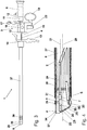
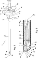
- a bipolar resectoscope 1 essentially consists of an inner shaft 2, an electrode transporter 3, a first electrode 4, a second electrode 5 and an optical system 6.
- the inner shaft 2 has an insulating insert 8 at its distal end 7 facing the patient.
- the electrode transporter 3 can be inserted into the inner shaft 2 from its proximal end 9 facing away from the distal end 7 and can be latched to the inner shaft 2.
- the electrode transporter 3 has a guide tube 10, at the proximal end 11 facing the surgeon a connector 12 for connecting the optics 6, which is guided in the guide tube 10, is arranged.
- the electrode transporter 3 has a finger grip 13 and a connection cone 14 located in the distal direction, which the electrode transporter 3 can be locked with a main body 15 forming the proximal end of the inner shaft 2.
- a longitudinally displaceable sliding body 16 is mounted on the guide tube 10.
- the sliding body 16 is connected to the connecting piece 12 via a resilient joint 17 and can be pressed against the spring force of the joint 17 in the direction of the finger grip 13 via a thumb ring 18.
- the sliding body 16 has a receiving opening for receiving a proximal end 19 of the first electrode 4.
- the sliding body 16 has a guide channel 20, with which the sliding body 16 is guided on the guide tube 10, the longitudinal axis 21 of the guide tube 10 coinciding with the longitudinal axis of the guide channel 20.
- the sliding body 16 has a plug receptacle 22 for a plug, not shown, which can be connected at an instrument-side end of a high-frequency cable to a first connection of a high-frequency generator, also not shown. Accordingly, the second electrode 5 can be connected at its proximal end to a second connection of the high-frequency generator.
- the first electrode 4 is forked in a known manner at its distal end 23 and has approximately parallel to the longitudinal axis 21 two parallel loop guide tubes 24, between which a semicircular cutting loop 25 is stretched.
- the cutting loop 25 is bent back in a proximal direction and forms an acute angle 26 with respect to the longitudinal axis 21 or with respect to the loop guide tubes 24.
- the insulating insert 8 has at its distal end 27 a circumferential, electrically conductive electrode surface 29 which is exposed transversely to the longitudinal axis 28 of the inner shaft 2 and which is connected on the inside 30 of the insulating insert to the distal end 31 of the second electrode 5 via an intermediate piece 32.
- the first electrode 4 is designed as an active cutting electrode, while the exposed electrode surface 29 of the insulating insert 8 is designed as a passive neutral electrode for returning the high-frequency current.
- the exposed electrode surface 29 of the insulating insert 8 is arranged on the outside 34 of the insulating insert 8 radially facing away from the longitudinal axis 33, the exposed electrode surface 29 of the insulating insert 8 being electrically insulated inwards, ie towards the inside 30 of the insulating insert 8.
- the electrode surface 29 on the roof-shaped upper side of the insulating insert 8 is wider and therefore narrower in the area of the lower side in the area of the cutting edge 36.
- the exposed electrode surface 29 of the insulating insert 8 is annular. That is, the electrode surface 29 is of equal width both in the roof area and in the area of the cutting edge 36.
- the exposed electrode surface 29 of the insulating insert 8 is arranged on the inside 30 of the insulating insert 8 radially facing the longitudinal axis 33, the exposed electrode surface 29 of the insulating insert 8 being electrically insulated radially towards the outside.
- the exposed electrode surfaces 29 are arranged insulated in the longitudinal direction on the one hand towards the distal end 27 of the insulating insert 8 and on the other hand towards the free or distal end 7 of the inner shaft.
- the insulating insert (8) is inserted with its proximal end 35 into the distal end 7 of the inner shaft 2.
- the intermediate piece 32 connected to the electrode surface 29 is connected to the distal end 31 of the second electrode 5 via a plug connection 40.
- the Plug connection 40 consists of a plug contact 41 which protrudes from the proximal end 35 of the insulating insert 8 and is electrically conductively connected to the intermediate piece 32, and of a contact sleeve 42 which forms the distal end 31 of the second electrode 5 and which is the free end of the Plug contact 41 takes.
- the insulating insert 8 is formed, for example, from a plastic, the exposed electrode surface 29 being made from a metallic material.
- the insulating insert 8 can, however, also be formed from a non-conductive ceramic, the exposed electrode surface 29 being formed from a metallized ceramic.
- the inner shaft 2 is arranged in an outer shaft 37, the two shafts 2, 37 forming a continuous rinsing shaft with continuous rinsing.
- the distal end 38 of the outer shaft 37 is set back in the proximal direction in the region of the insulating insert 8, that is to say spaced, relative to the distal end 27 of the insulating insert 8.
- the outer shaft 37 has a plurality of reflux openings 39 at its distal end 38.
- both the inner shaft 2 and the outer shaft 37 are formed from an electrically conductive material.
- the passive electrode transporter shown in the exemplary embodiment can also be designed as an active electrode transporter known to the person skilled in the art.
- the person skilled in the art for coagulating tissue can replace the cutting electrode 4 with a coagulation electrode known to the person skilled in the art.
- the second electrode 5 arranged in the inner shaft 2 does not have to be arranged at the bottom in the region of the cutting edge 36 or at the top, as shown in the exemplary embodiments. The person skilled in the art will consider them with regard to the arrangement of the optics and the electrode guide tube (not shown) of the electrode transporter 3 at a suitable point in the Arrange inner shaft 2.
Landscapes
- Health & Medical Sciences (AREA)
- Life Sciences & Earth Sciences (AREA)
- Surgery (AREA)
- Engineering & Computer Science (AREA)
- Veterinary Medicine (AREA)
- General Health & Medical Sciences (AREA)
- Nuclear Medicine, Radiotherapy & Molecular Imaging (AREA)
- Physics & Mathematics (AREA)
- Biomedical Technology (AREA)
- Heart & Thoracic Surgery (AREA)
- Medical Informatics (AREA)
- Molecular Biology (AREA)
- Animal Behavior & Ethology (AREA)
- Public Health (AREA)
- Otolaryngology (AREA)
- Plasma & Fusion (AREA)
- Biophysics (AREA)
- Optics & Photonics (AREA)
- Pathology (AREA)
- Radiology & Medical Imaging (AREA)
- Surgical Instruments (AREA)
Description
Die Erfindung betrifft ein bipolares Resektoskop, umfassend
- einen Außenschaft, der komplett aus einem elektrisch leitenden Material ausgebildet ist und der an seinem distalen Ende eine Mehrzahl von Rückflussöffnungen aufweist,
- einen in dem Außenschaft anordenbaren Innenschaft aus einem elektrisch leitenden Material mit einem an seinem distalen Ende angeordneten Isoliereinsatz aus einem elektrisch nicht leitenden Material,
- wobei über die Rückflussöffnungen (39) des Außenschaftes (37) zwischen dem Außenschaft (37) und dem Innenschaft (2) ein Rückfluss von Spülflüssigkeit ermöglicht wird,
- einen in dem Innenschaft anordenbaren Elektrodentransporteur,
- eine in dem Elektrodentransporteur längsverschieblich anordenbare erste Elektrode, die an ihrem dem distalen Ende abgewandten proximalen Ende mit einem ersten Anschluss eines Hochfrequenzgenerators verbindbar ist und die an ihrem distalen Ende gabelförmig geteilt ist und parallel zur Längsachse zwei parallele Schlingenführungsrohre aufweist, zwischen denen eine halbkreisförmige Schneidschlinge aufgespannt ist, und
- eine zweite Elektrode, die an ihrem proximalen Ende mit einem zweiten Anschluss des Hochfrequenzgenerators verbindbar ist.
- an outer shaft which is made entirely of an electrically conductive material and which has a plurality of reflux openings at its distal end,
- an inner shaft made of an electrically conductive material that can be arranged in the outer shaft with an insulating insert made of an electrically non-conductive material arranged at its distal end,
- a backflow of rinsing liquid is made possible via the reflux openings (39) of the outer shaft (37) between the outer shaft (37) and the inner shaft (2),
- an electrode transporter that can be arranged in the inner shaft,
- a first electrode which can be arranged in a longitudinally displaceable manner in the electrode transporter, which can be connected at its proximal end facing away from the distal end to a first connection of a high-frequency generator and which is forked at its distal end and has two parallel loop guide tubes parallel to the longitudinal axis, between which a semicircular cutting loop is stretched is and
- a second electrode, which can be connected at its proximal end to a second connection of the high-frequency generator.
Aus der
An seinem distalen Ende weist das bekannte Resektoskop einen Isoliereinsatz aus einem elektrisch nicht leitenden Material auf.At its distal end, the known resectoscope has an insulating insert made of an electrically non-conductive material.
Problematisch bei einem bipolaren Resektoskop ist, dass die aktive oder Schneidelektrode zur Erzielung einer hohen Schneidwirkung eine relativ geringe Schneidfläche und die passive oder Neutralelektrode zur Vermeidung einer eigenen Schneidwirkung relativ großflächig ausgebildet sein muss.The problem with a bipolar resectoscope is that the active or cutting electrode has to have a relatively small cutting surface in order to achieve a high cutting effect and the passive or neutral electrode has to be designed with a relatively large area to avoid its own cutting effect.
Aus der
Nachteilig dabei ist, dass zum einen die Neutralelektrode zusammen mit der Schneidelektrode ausgetauscht werden muss und dass zum anderen der zusätzliche Isolationsträger mit der freiliegenden Elektrodenfläche unerwünscht das Blickfeld der Endoskopoptik einschränkt.The disadvantage here is that, on the one hand, the neutral electrode must be replaced together with the cutting electrode, and on the other hand, the additional insulation support with the exposed electrode surface undesirably limits the field of view of the endoscope optics.
Aus der
Weiterhin ist aus der
Nachteilig dabei ist, dass zum einen der Abstand in Längsrichtung zwischen erster und zweiter Elektrode relativ groß sein muss und unerwünscht in proximale Richtung verlagert ist und dass es zum anderen bei defekter Isolierung des Außenschaftes zu unerwünschten Stromdichten und damit zu unerwünschten Verbrennungen kommen kann.The disadvantage here is that, on the one hand, the distance in the longitudinal direction between the first and second electrodes must be relatively large and is undesirably displaced in the proximal direction, and on the other hand, if the outer shaft is defective, undesired current densities and thus undesirable burns can occur.
Weiterhin ist aus der
Nachteilig dabei ist, dass das elektrisch leitende Rohrstück vom distalen Ende des Endoskopschaftes durch einen zusätzlichen Isolierring elektrisch getrennt sein muss. Dieser Isolierring muss als zusätzliches Teil mit dem distalen Ende des Endoskopschaftes einerseits und mit dem dem distalen Ende des Endoskopschaftes zugewandten proximalen Ende des Rohrstückes andererseits relativ kostenintensiv verbunden werden. Weiterhin nachteilig ist, dass das elektrisch leitende Rohrstück sowohl in radialer Richtung nach außen als auch in radialer Richtung nach innen Strom ableitet, was in Verbindung mit dem umliegenden Gewebe und der Stellung des Endoskopschaftes zu unterschiedlichen ableitenden Stromflächen und damit zu unterschiedlichen und veränderlichen Stromdichten führt.The disadvantage here is that the electrically conductive tube piece must be electrically separated from the distal end of the endoscope shaft by an additional insulating ring. This insulating ring has to be connected as an additional part to the distal end of the endoscope shaft on the one hand and to the proximal end of the tube piece facing the distal end of the endoscope shaft on the other hand at relatively high cost. A further disadvantage is that the electrically conductive tube piece conducts current both in the radial direction outwards and in the radial direction inwards, which in connection with the surrounding tissue and the position of the endoscope shaft different discharge current areas and thus leads to different and variable current densities.
Aus der
Nachteilig bei dem bekannten bipolaren Resektoskop ist, dass der Metallschaft mit einer isolierenden Außenschicht und mit einer isolierenden Innenschicht versehen sein muss. Dies ist zum einen aufwendig und kostenintensiv. Zum anderen können insbesondere Beschädigungen oder Kratzer in der Außenschicht zu unerwünschten Harnröhrenstrikturen führen. Weiterhin nachteilig ist, dass die Elektrodenfläche in einem relativ großen Abstand zum Isoliereinsatz angeordnet sein muss und unerwünscht weit zurück in der Harnröhre positioniert ist.A disadvantage of the known bipolar resectoscope is that the metal shaft must be provided with an insulating outer layer and with an insulating inner layer. On the one hand, this is complex and cost-intensive. On the other hand, damage or scratches in the outer layer can lead to undesirable urethral strictures. Another disadvantage is that the electrode surface must be arranged at a relatively large distance from the insulating insert and undesirably positioned far back in the urethra.
Aus der
Aus der
Aus der
Aufgabe der vorliegenden Erfindung ist es daher, ein gattungsgemäßes biopolares Resektoskop derart weiterzubilden, dass die zweite Elektrode als passive Elektrode mit ausreichend großer Elektrodenfläche möglichst nah an der ersten Elektrode, die als aktive Elektrode ausgebildet ist, angeordnet ist. Wobei elektrische Sicherheit einerseits und eine möglichst geringe Beeinträchtigung des Sichtfeldes andererseits kostengünstig gegeben sein soll.The object of the present invention is therefore to develop a generic biopolar resectoscope in such a way that the second electrode is arranged as a passive electrode with a sufficiently large electrode area as close as possible to the first electrode, which is designed as an active electrode. Electrical safety on the one hand and the least possible impairment of the field of vision on the other hand should be given inexpensively.
Diese Aufgabe wird in Verbindung mit den Merkmalen des Anspruchs 1 dadurch gelöst, dass der Isoliereinsatz an seinem distalen Ende eine umlaufende, elektrisch leitende und quer zur Längsachse des Innenschaftes freiliegende Elektrodenfläche aufweist, die an der Innenseite des Isoliereinsatzes mit dem distalen Ende der zweiten Elektrode verbunden ist, dass die freiliegende Elektrodenfläche des Isoliereinsatzes in Längsrichtung einerseits zu dem distalen Ende des Isoliereinsatzes hin und andererseits zu dem freien Ende des Innenschaftes hin isoliert angeordnet ist, und dass die freiliegende Elektrodenfläche des Isoliereinsatzes an der der Längsachse radial abgewandten Außenseite des Isoliereinsatzes angeordnet und nach innen hin elektrisch isoliert ist.This object is achieved in connection with the features of claim 1 in that the insulating insert has at its distal end a circumferential, electrically conductive electrode surface which is exposed transversely to the longitudinal axis of the inner shaft and which is connected to the distal end of the second electrode on the inside of the insulating insert is that the exposed electrode surface of the insulating insert is arranged insulated in the longitudinal direction on the one hand towards the distal end of the insulating insert and on the other hand towards the free end of the inner shaft, and that the exposed electrode surface of the insulating insert is arranged on the outside of the insulating insert radially facing away from the longitudinal axis and after is electrically insulated on the inside.
Durch die Anordnung einer freiliegenden Elektrodenfläche am Isoliereinsatz des Innenschaftes entsteht eine passive Elektrodenfläche von ausreichender Größe in der Nähe der ersten Elektrode ohne die Sicht gegenüber der Verwendung eines üblichen komplett nicht leitenden Isoliereinsatzes einzuschränken. Für den Fachmann überraschend ergeben sich dabei sehr gute Schneideigenschaften im Gewebe. Der Außenschaft kann dabei komplett leitend oder auch komplett aus einem nicht leitenden Material ausgebildet sein. In beiden Fällen erfolgt keine Ableitung von Strom über den Außenschaft. Somit sind auch eine hohe elektrische Sicherheit und ein Schutz vor unerwünschten Verbrennungen durch Ableitung von Strom über den Außenschaft gegeben. Durch die Isolierung der freiliegenden Elektrodenfläche auf der Außenseite oder auf der Innenseite des Isoliereinsatzes gibt es jeweils eine definierte Elektrodenfläche. Überraschend zeigt sich hier, dass es trotz kurzer Stromwege zwischen den beiden Elektroden nicht zu einem die Schneidwirkung beeinträchtigenden Stromfluss kommt. Ein zusätzlicher, relativ kostenintensiver Isolierring gegenüber dem Innenschaft wird nicht benötigt.The arrangement of an exposed electrode surface on the insulating insert of the inner shaft creates a passive electrode surface of sufficient size in the vicinity of the first electrode without restricting the view compared to the use of a conventional completely non-conductive insulating insert. Surprisingly for the expert, this results in very good cutting properties in the tissue. The outer shaft can be completely conductive or completely made of a non-conductive Material be formed. In both cases, there is no discharge of electricity via the outer shaft. This also ensures a high level of electrical safety and protection against undesirable burns by dissipating current through the outer shaft. Due to the insulation of the exposed electrode surface on the outside or on the inside of the insulating insert, there is a defined electrode surface in each case. Surprisingly, it can be seen here that despite the short current paths between the two electrodes, there is no current flow impairing the cutting effect. An additional, relatively costly insulating ring opposite the inner shaft is not required.
Diese Aufgabe wird in Verbindung mit den Merkmalen des Anspruchs 2 weiterhin dadurch gelöst, dass der Isoliereinsatz an seinem distalen Ende eine umlaufende, elektrisch leitende und quer zur Längsachse des Innenschaftes freiliegende Elektrodenfläche aufweist, die an der Innenseite des Isoliereinsatzes mit dem distalen Ende der zweiten Elektrode verbunden ist, dass die freiliegende Elektrodenfläche des Isoliereinsatzes in Längsrichtung einerseits zu dem distalen Ende des Isoliereinsatzes hin und andererseits zu dem freien Ende des Innenschaftes hin isoliert angeordnet ist, und dass die freiliegende Elektrodenfläche des Isoliereinsatzes an der der Längsachse radial zugewandten Innenseite des Isoliereinsatzes angeordnet und nach außen hin elektrisch isoliert ist.This object is further achieved in connection with the features of
Gemäß einer bevorzugten Ausführungsform der Erfindung ist die erste Elektrode als eine aktive Schneidelektrode und die freiliegende Elektrodenfläche des Isoliereinsatzes als eine passive Neutralelektrode ausgebildet.According to a preferred embodiment of the invention, the first electrode is designed as an active cutting electrode and the exposed electrode surface of the insulating insert as a passive neutral electrode.
Gemäß einer weiteren Ausführungsform der Erfindung ist der Isoliereinsatz aus einem Kunststoff ausgebildet und die freiliegende Elektrodenfläche ist aus einem metallischen Werkstoff ausgebildet. Die Elektrodenfläche kann dabei in dem Isoliereinsatz eingebettet sein.According to a further embodiment of the invention, the insulating insert is made of a plastic and the exposed electrode surface is made of a metallic material. The electrode surface can be embedded in the insulating insert.
Alternativ kann der Isoliereinsatz aus einer nicht leitenden Keramik ausgebildet und die freiliegende Elektrodenfläche aus einer metallisierten und damit leitenden Keramik ausgebildet sein.Alternatively, the insulating insert can be made of a non-conductive ceramic and the exposed electrode surface can be made of a metallized and thus conductive ceramic.
Gemäß einer weiteren bevorzugten Ausführungsform der Erfindung ist der Innenschaft in einem Außenschaft anordenbar und die beiden Schäfte bilden einen Dauerspülschaft mit kontinuierlicher Spülung.According to a further preferred embodiment of the invention, the inner shaft can be arranged in an outer shaft and the two shafts form a continuous rinsing shaft with continuous rinsing.
Nach einer weiteren bevorzugten Ausführungsform der Erfindung ist das distale Ende des Außenschaftes gegenüber dem distalen Ende des Isoliereinsatzes in proximaler Richtung im Bereich des Isoliereinsatzes zurückgesetzt. Dabei weist der Außenschaft an seinem distalen Ende eine Mehrzahl von Rückflussöffnungen auf. Über die Rückflussöffnungen wird ein Rückfluss von Spülflüssigkeit zwischen dem Innenschaft und dem Außenschaft ermöglicht.According to a further preferred embodiment of the invention, the distal end of the outer shaft is set back in the proximal direction in relation to the distal end of the insulating insert in the region of the insulating insert. The outer shaft has a plurality of reflux openings at its distal end. A backflow of rinsing liquid between the inner shaft and the outer shaft is made possible via the backflow openings.
Nach einer weiteren bevorzugten Ausführungsform der Erfindung ist der Isoliereinsatz mit seinem proximalseitigen Ende in das distale Ende des Innenschaftes eingesteckt und das mit der Elektrodenfläche verbundene Zwischenstück ist über eine Steckverbindung mit dem distalen Ende der zweiten Elektrode verbunden.According to a further preferred embodiment of the invention, the insulating insert is inserted with its proximal end into the distal end of the inner shaft and the intermediate piece connected to the electrode surface is connected to the distal end of the second electrode via a plug connection.
Dadurch ist es möglich, den Isoliereinsatz mit der Elektrodenfläche leicht auszutauschen. Auch können unterschiedliche Isoliereinsätze mit unterschiedlichen Elektrodenflächen eingesetzt werden.This makes it possible to easily replace the insulating insert with the electrode surface. Different insulating inserts with different electrode surfaces can also be used.
Weitere Merkmale und Vorteile der Erfindung ergeben sich aus der nachfolgenden speziellen Beschreibung und den Zeichnungen.Further features and advantages of the invention result from the following special description and the drawings.
Es zeigen:
- Figur 1:
- eine Seitenansicht eines bipolaren Resektoskopes mit gestrichelt angedeuteter Optik;
- Figur 2:
- eine Seitenansicht des distalen Endes von
Fig. 1 im Schnitt und vergrößerter Darstellung; - Figur 3:
- eine Seitenansicht eines bipolaren Resektoskopes einer zweiten Ausführungsform mit gestrichelt angedeuteter Optik;
- Figur 4:
- eine Seitenansicht des distalen Endes von
Fig. 3 im Schnitt und vergrößerter Darstellung; - Figur 5:
- eine Seitenansicht eines bipolaren Resektoskopes einer dritten Ausführungsform mit gestrichelt angedeuteter Optik;
- Figur 6:
- eine Seitenansicht des distalen Endes von
Fig. 5 im Schnitt und vergrößerter Darstellung; - Figur 7:
- eine Seitenansicht im Schnitt des bipolaren Resektoskopes von
Fig. 5 ohne Optik; - Figur 8:
- eine Seitenansicht des distalen Endes eines Innenschaftes mit Isoliereinsatz in vergrößerter Darstellung;
- Figur 9:
- eine Seitenansicht des distalen Endes von
Fig. 8 im Schnitt; - Figur 10:
- eine Seitenansicht des distalen Endes von
Fig. 8 mit herausgezogenem Isoliereinsatz und - Figur 11:
- eine Seitenansicht des distalen Endes von
Fig. 10 im Schnitt.
- Figure 1:
- a side view of a bipolar resectoscope with optics indicated by dashed lines;
- Figure 2:
- a side view of the distal end of
Fig. 1 in section and enlarged view; - Figure 3:
- a side view of a bipolar resectoscope of a second embodiment with optics indicated by dashed lines;
- Figure 4:
- a side view of the distal end of
Fig. 3 in section and enlarged view; - Figure 5:
- a side view of a bipolar resectoscope of a third embodiment with optics indicated by dashed lines;
- Figure 6:
- a side view of the distal end of
Fig. 5 in section and enlarged view; - Figure 7:
- a side view in section of the bipolar resectoscope of
Fig. 5 without optics; - Figure 8:
- a side view of the distal end of an inner shaft with insulating insert in an enlarged view;
- Figure 9:
- a side view of the distal end of
Fig. 8 on average; - Figure 10:
- a side view of the distal end of
Fig. 8 with pulled out insulation insert and - Figure 11:
- a side view of the distal end of
Fig. 10 on average.
Ein bipolares Resektoskop 1 besteht im Wesentlichen aus einem Innenschaft 2, einem Elektrodentransporteur 3, einer ersten Elektrode 4, einer zweiten Elektrode 5 und einer Optik 6.A bipolar resectoscope 1 essentially consists of an
Der Innenschaft 2 weist an seinem dem Patienten zugewandten distalen Ende 7 einen Isoliereinsatz 8 auf. In den Innenschaft 2 ist von dessen dem distalen Ende 7 abgewandten proximalen Ende 9 her der Elektrodentransporteur 3 einsetzbar und mit dem Innenschaft 2 verrastbar.The
Der Elektrodentransporteur 3 weist ein Führungsrohr 10 auf, an dessen dem Operateur zugewandten proximalen Ende 11 ein Anschlussstück 12 zum Anschluss der Optik 6, die in dem Führungsrohr 10 geführt wird, angeordnet ist. Der Elektrodentransporteur 3 weist einen Fingergriff 13 und einen in distaler Richtung vorlagerten Anschlusskonus 14 auf, den der Elektrodentransporteur 3 mit einem das proximale Ende des Innenschaftes 2 bildenden Hauptkörper 15 verriegelbar ist.The
Auf dem Führungsrohr 10 ist ein längsverschieblicher Schiebekörper 16 gelagert. Über ein federndes Gelenk 17 ist der Schiebekörper 16 mit dem Anschlussstück 12 verbunden und kann über einen Daumenring 18 gegen die Federkraft des Gelenkes 17 in Richtung Fingergriff 13 gedrückt werden. Der Schiebekörper 16 weist eine Aufnahmeöffnung zur Aufnahme eines proximalen Endes 19 der ersten Elektrode 4 auf. Der Schiebekörper 16 weist einen Führungskanal 20 auf, mit der Schiebekörper 16 auf dem Führungsrohr 10 geführt wird, wobei die Längsachse 21 des Führungsrohres 10 mit der Längsachse des Führungskanals 20 zusammenfällt. Quer zur Längsachse 21 weist der Schiebekörper 16 eine Steckeraufnahme 22 für einen nicht dargestellten Stecker, der an einem instrumentenseitigen Ende eines Hochfrequenzkabels mit einem ersten Anschluss eines ebenfalls nicht dargestellten Hochfrequenzgenerators verbindbar ist. Entsprechend ist die zweite Elektrode 5 an ihrem proximalen Ende mit einem zweiten Anschluss des Hochfrequenzgenerators verbindbar.A longitudinally
Die erste Elektrode 4 ist in an sich bekannter Weise an ihrem distalen Ende 23 gabelförmig geteilt und weist etwa parallel zur Längsachse 21 zwei parallele Schlingenführungsrohre 24 auf, zwischen denen eine halbkreisförmige Schneidschlinge 25 aufgespannt wird. In den Ausführungsbeispielen ist die Schneidschlinge 25 in einer proximalen Richtung zurückgebogen und bildet die gegen die Längsachse 21 bzw. gegenüber den Schlingenführungsrohren 24 einen spitzen Winkel 26.The
Der Isoliereinsatz 8 weist an seinem distalen Ende 27 eine umlaufenden, elektrisch leitende und quer zur Längsachse 28 des Innenschaftes 2 freiliegenden Elektrodenfläche 29 auf, die an der Innenseite 30 des Isoliereinsatzes mit dem distalen Ende 31 der zweiten Elektrode 5 über ein Zwischenstück 32 verbunden ist.The insulating
Gemäß den Ausführungsbeispielen ist die erste Elektrode 4 als eine aktive Schneidelektrode ausgebildet, während die freiliegenden Elektrodenfläche 29 des Isoliereinsatzes 8 als eine passive Neutralelektrode zur Rückführung des Hochfrequenzstromes ausgebildet ist.According to the exemplary embodiments, the
Gemäß den Ausführungsbeispielen der
Entsprechend den Ausführungsbeispielen der
Entsprechend den Ausführungsbeispielen der
Entsprechend den Ausführungsbeispielen der
Die freiliegenden Elektrodenflächen 29 ist entsprechend den Ausführungsbeispielen in Längsrichtung einerseits zu dem distalen Ende 27 des Isoliereinsatzes 8 hin und andererseits zu dem freien oder distalen Ende 7 des Innenschaftes hin isoliert angeordnet.According to the exemplary embodiments, the exposed electrode surfaces 29 are arranged insulated in the longitudinal direction on the one hand towards the
Entsprechend den Ausführungsbeispielen der
Der Isoliereinsatz 8 ist beispielsweise aus einem Kunststoff ausgebildet, wobei die freiliegende Elektrodenfläche 29 aus einem metallischen Werkstoff ausgebildet ist. Der Isoliereinsatz 8 kann aber auch aus einer nicht leitenden Keramik ausgebildet sein, wobei die freiliegende Elektrodenfläche 29 aus einer metallisierten Keramik ausgebildet ist.The insulating
Entsprechend den Ausführungsbeispielen ist der Innenschaft 2 in einem Außenschaft 37 angeordnet, wobei die beiden Schäfte 2, 37 einen Dauerspülschaft mit kontinuierlicher Spülung bilden. Dabei ist das distale Ende 38 des Außenschaftes 37 gegenüber dem distalen Ende 27 des Isoliereinsatzes 8 in proximaler Richtung im Bereich des Isoliereinsatzes 8 zurückgesetzt, also beabstandet.According to the exemplary embodiments, the
Der Außenschaft 37 weist an seinem distalen Ende 38 eine Mehrzahl von Rückflussöffnungen 39 auf.The
Entsprechend den Ausführungsbeispielen sind sowohl der Innenschaft 2 als auch der Außenschaft 37 aus einem elektrisch leitenden Material ausgebildet.According to the exemplary embodiments, both the
Natürlich stellen die in der speziellen Beschreibung diskutierten und in den Figuren gezeigten Ausführungsformen nur illustrative Ausführungsbeispiele der vorliegenden Erfindung dar. Dem Fachmann ist im Lichte der hiesigen Offenbarung ein breites Spektrum von Variationsmöglichkeiten an die Hand gegeben. Insbesondere kann der im Ausführungsbeispiel dargestellte passive Elektrodentransporteur auch als ein dem Fachmann bekannter aktiver Elektrodentransporteur ausgebildet sein. Selbstverständlich kann der Fachmann zum koagulieren von Gewebe die Schneidelektrode 4 durch eine dem Fachmann bekannte Koagulationselektrode ersetzen. Die in dem Innenschaft 2 angeordnete zweite Elektrode 5 muss nicht wie in den Ausführungsbeispielen gezeigt, unten im Bereich der Schneidkante 36 oder oben angeordnet sein. Der Fachmann wird sie im Hinblick auf die Anordnung von Optik und des nicht dargestellten Elektrodenführungsrohres des Elektrodentransporteurs 3 an geeigneter Stelle des Innenschaftes 2 anordnen.Of course, the embodiments discussed in the specific description and shown in the figures represent only illustrative exemplary embodiments of the present invention. In the light of the disclosure herein, the person skilled in the art is provided with a broad spectrum of possible variations. In particular, the passive electrode transporter shown in the exemplary embodiment can also be designed as an active electrode transporter known to the person skilled in the art. Of course, the person skilled in the art for coagulating tissue can replace the cutting
- 11
- bipolares Resektoskopbipolar resectoscope
- 22
- Innenschaftinner shaft
- 33
- Elektrodentransporteurelectrode carrier
- 44
- erste Elektrodefirst electrode
- 55
- zweite Elektrodesecond electrode
- 66
- Optikoptics
- 77
- distales Ende von 2distal end of 2
- 88th
- Isoliereinsatz von 2Insulation insert from 2
- 99
- proximales Ende von 2proximal end of 2
- 1010
- Führungsrohr von 3Guide tube of 3
- 1111
- proximales Ende von 3proximal end of 3
- 1212
- Anschlussstück von 3Connector from 3
- 1313
- Fingergriff von 3Finger grip from 3
- 1414
- Anschlusskörper von 3Connection body from 3
- 1515
- Hauptkörper von 2Main body of 2
- 1616
- Schiebekörper von 3Sliding body of 3
- 1717
- Gelenk von 3Joint of 3
- 1818
- Daumenring von 16Thumb ring from 16
- 1919
- proximales Ende von 4proximal end of 4
- 2020
- Führungskanal von 16Guide channel of 16
- 2121
- Längsachse von 10Longitudinal axis of 10
- 2222
- Steckeraufnahmeplug receptacle
- 2323
- distales Ende von 4distal end of 4
- 2424
- Schlingenführungsrohr von 4Loop guide tube of 4
- 2525
- Schneidschlingecutting loop
- 2626
- Winkel von 25Angle of 25
- 2727
- distales Ende von 8distal end of 8
- 2828
- Längsachse von 2Longitudinal axis of 2
- 2929
- Elektrodenfläche von 8Electrode area of 8
- 3030
- Innenseite von 8Inside of 8
- 3131
- distales Ende von 5distal end of 5
- 3232
- Zwischenstück von 5 und 8Intermediate piece of 5 and 8
- 3333
- Längsachse von 8Longitudinal axis of 8
- 3434
- Außenseite von 8Outside of 8
- 3535
- proximales Ende von 8proximal end of 8
- 3636
- Schneidkante von 8Cutting edge of 8
- 3737
- Außenschaftouter shaft
- 3838
- distales Ende von 37distal end of 37
- 3939
- RückflussöffnungenFeedback openings
- 4040
- Steckverbindungconnector
- 4141
- Steckkontakt von 8Plug contact from 8
- 4242
- Kontakthülse von 4Contact sleeve from 4
Claims (8)
- A bipolar resectoscope (1), comprising- an outer shaft (37) made entirely of an electrically conductive material and having at its distal end a plurality of return flow openings (39),- an inner shaft (2) arranged within the outer shaft (37), made of an electrically conductive material, with an insulating insert (8) made of an electrically nonconductive material arranged at its distal end (7), whereby a return flow of flushing fluid is enabled between the outer shaft (37) and the inner shaft (2) via the return flow openings (39) of the outer shaft (37),- an electrode transporter (3) that can be arranged within the inner shaft (2),- a first electrode (4) that can be arranged within the electrode transporter (3) in a longitudinally displaceable manner and that, at its proximal end (19) facing away from the distal end, can be connected to a first connection of a high frequency generator and is divided in a fork shape at its distal end (23) and has two parallel cutting loop guide tubes (24) parallel to the longitudinal axis (21), between which a semicircular cutting loop (25) is stretched open, and- a second electrode (5) which can be connected at its proximal end to a second connection of the high-frequency generator,wherein, at its distal end (27), the insulating insert (8) has a circumferential electrically conductive electrode surface (29) that is exposed transversely to the longitudinal axis (28) of the inner shaft (2), the exposed electrode surface being connected to the distal end (31) of the second electrode (5) on the inner side (30) of the insulating insert (8); wherein the exposed electrode surface (29) of the insulating insert (8) is arranged so as to be insulated in the longitudinal direction toward the distal end (27) of the insulating insert (8), on the one hand, and toward the free end (7) of the inner shaft, on the other hand; and
wherein the exposed electrode surface (29) of the insulating insert (8) is arranged on the outer side (34), facing radially away from the longitudinal axis (33), of the insulating insert (8), and is electrically insulated toward the inside. - A bipolar resectoscope (1), comprising- an outer shaft (37) made entirely of an electrically conductive material and having at its distal end a plurality of return flow openings (39),- an inner shaft (2) made of an electrically conductive material that can be arranged within the outer shaft (37), with an insulating insert (8) made of an electrically nonconductive material at its distal end (7), whereby a return flow of flushing fluid is enabled via the return flow openings (39) of the outer shaft (37) between the outer shaft (37) and the inner shaft (2),- an electrode transporter (3) that can be arranged within the inner shaft (2),- a first electrode (4) that can be arranged within the electrode transporter (3) in a longitudinally displaceable manner which, at its proximal end (19) facing away from the distal end, can be connected to a first connection of a high frequency generator and is divided in a fork shape at its distal end (23) and has two parallel cutting loop guide tubes (24) parallel to the longitudinal axis (21), between which a semi-circular cutting loop (25) is stretched open, and- a second electrode (5), which can be connected at its proximal end to a second connection of the high-frequency generator,wherein at its distal end (27), the insulating insert (8) has a circumferential electrically conductive electrode surface (29) that is exposed transversely to the longitudinal axis (28) of the inner shaft (2), the exposed electrode surface being connected to the distal end (31) of the second electrode (5) on the inner side (30) of the insulating insert (8); wherein the exposed electrode surface (29) of the insulating insert (8) is arranged so as to be insulated in the longitudinal direction toward the distal end (27) of the insulating insert (8), on the one hand, and toward the free end (7) of the inner shaft (2), on the other hand; and
wherein the exposed electrode surface (29) of the insulating insert (8) is arranged on the inner side (30), facing radially toward the longitudinal axis (33), of the insulating insert (8), and is electrically insulated toward the outside. - The bipolar resectoscope according to claim 1 or 2,
characterized in that
the first electrode (4) is designed as an active cutting electrode and the exposed electrode surface (29) of the insulating insert (8) is designed as a passive neutral electrode. - The bipolar resectoscope according to any of claims 1 to 3,
characterized in that
the insulating insert (8) is made of plastic and that the exposed electrode surface (29) is made of a metallic material. - The bipolar resectoscope according to any of claims 1 to 3,
characterized in that
the insulating insert (8) is made of a ceramic material and
the exposed electrode surface (29) is made of a metalized ceramic material. - The bipolar resectoscope according to any of claims 1 to 5,
characterized in that
the two shafts (2, 37) form a continuous flushing shaft with continuous flushing. - The bipolar resectoscope according to claim 6,
characterized in that
the distal end (38) of the outer shaft (37) is set back relative to the distal end (27) of the insulating insert (8) in the proximal direction, in the area of the insulating insert (8). - The bipolar resectoscope according to any of claims 1 to 7,
characterized in that
the proximal-side end (35) of the insulating insert (8) is inserted into the distal end (7) of
the inner shaft (2) and that
the adapter (32) connected to the electrode surface (29) is connected to the distal end (31) of the second electrode (5) via a plug connector (40).
Applications Claiming Priority (2)
| Application Number | Priority Date | Filing Date | Title |
|---|---|---|---|
| DE102013001156.6A DE102013001156B4 (en) | 2013-01-24 | 2013-01-24 | Bipolar resectoscope |
| PCT/EP2014/051048 WO2014114600A1 (en) | 2013-01-24 | 2014-01-20 | Bipolar resectoscope |
Publications (2)
| Publication Number | Publication Date |
|---|---|
| EP2948086A1 EP2948086A1 (en) | 2015-12-02 |
| EP2948086B1 true EP2948086B1 (en) | 2020-02-05 |
Family
ID=50073149
Family Applications (1)
| Application Number | Title | Priority Date | Filing Date |
|---|---|---|---|
| EP14703785.7A Active EP2948086B1 (en) | 2013-01-24 | 2014-01-20 | Bipolar resectoscope |
Country Status (4)
| Country | Link |
|---|---|
| US (1) | US20150351826A1 (en) |
| EP (1) | EP2948086B1 (en) |
| DE (1) | DE102013001156B4 (en) |
| WO (1) | WO2014114600A1 (en) |
Families Citing this family (19)
| Publication number | Priority date | Publication date | Assignee | Title |
|---|---|---|---|---|
| DE102014115487A1 (en) * | 2014-10-23 | 2016-04-28 | Olympus Winter & Ibe Gmbh | Hand instrument for surgical procedures |
| DE102015004328B4 (en) * | 2015-04-09 | 2019-05-16 | Olympus Winter & Ibe Gmbh | Transporter and plug of a resectoscope |
| FR3036278B1 (en) | 2015-05-20 | 2017-06-23 | Ab Medica | DEVICE FOR REALIZING THE RESECTION OF AN ORGAN IN A CAVITY OF A LIVING BODY |
| US10383682B2 (en) | 2015-08-28 | 2019-08-20 | Covidien Lp | Powered bipolar resectoscope |
| US10869716B2 (en) | 2015-08-28 | 2020-12-22 | Covidien Lp | Powered bipolar resectoscope |
| USD820444S1 (en) * | 2016-08-12 | 2018-06-12 | Karl Storz Gmbh & Co. Kg | Resectoscope shaft for cold enucleation |
| CN107212920A (en) * | 2017-01-23 | 2017-09-29 | 杭州安杰思医学科技有限公司 | Endoscope-use processing unit, endoscope and expandable stent |
| DE102017118885B3 (en) | 2017-08-18 | 2018-12-27 | Bowa Electronic Gmbh & Co. Kg | Bipolar resectoscope |
| DE102018127919A1 (en) | 2018-11-08 | 2020-05-14 | Karl Storz Se & Co. Kg | Electrode arrangement for a bipolar resectoscope and resectoscope |
| JP7189971B2 (en) * | 2019-01-28 | 2022-12-14 | オリンパス株式会社 | Electrode unit and endoscope system |
| DE102019102839A1 (en) | 2019-02-05 | 2020-08-06 | Olympus Winter & Ibe Gmbh | Irrigation fluid for resection |
| DE102019102841A1 (en) | 2019-02-05 | 2020-08-06 | Olympus Winter & Ibe Gmbh | Detachable insulating insert for use in a resectoscope |
| US11766288B2 (en) * | 2019-02-22 | 2023-09-26 | Gyrus Acmi, Inc. | Flexible bipolar sheath |
| US11717342B2 (en) | 2019-04-11 | 2023-08-08 | Gyrus Acmi, Inc. | Medical device |
| CN110123255A (en) * | 2019-06-04 | 2019-08-16 | 北京大学第一医院 | A kind of multi-functional cavity inspection and treatment endoscope system |
| DE102019132536B3 (en) * | 2019-11-29 | 2021-05-06 | Olympus Winter & Ibe Gmbh | Conveyor with locking device |
| DE102019135571A1 (en) * | 2019-12-20 | 2021-06-24 | Olympus Winter & Ibe Gmbh | Resectoscope with distal electrode guide |
| DE102020118965A1 (en) * | 2020-07-17 | 2022-02-10 | Olympus Winter & Ibe Gmbh | Surgical handpiece, insulating liner for a surgical handpiece and method of handling a surgical handpiece |
| EP4236847A1 (en) * | 2020-10-28 | 2023-09-06 | United States Endoscopy Group, Inc. | Cap for endoscope |
Family Cites Families (14)
| Publication number | Priority date | Publication date | Assignee | Title |
|---|---|---|---|---|
| DE2521719C2 (en) * | 1975-05-15 | 1985-06-20 | Delma, Elektro- Und Medizinische Apparatebaugesellschaft Mbh, 7200 Tuttlingen | Electrosurgical device |
| US5007908A (en) * | 1989-09-29 | 1991-04-16 | Everest Medical Corporation | Electrosurgical instrument having needle cutting electrode and spot-coag electrode |
| US6730081B1 (en) * | 1991-10-18 | 2004-05-04 | Ashvin H. Desai | Endoscopic surgical instrument |
| US5902272A (en) | 1992-01-07 | 1999-05-11 | Arthrocare Corporation | Planar ablation probe and method for electrosurgical cutting and ablation |
| US6632193B1 (en) * | 1995-06-07 | 2003-10-14 | Arthrocare Corporation | Systems and methods for electrosurgical tissue treatment |
| US6015406A (en) * | 1996-01-09 | 2000-01-18 | Gyrus Medical Limited | Electrosurgical instrument |
| WO1997024074A1 (en) | 1995-12-29 | 1997-07-10 | Microgyn, Inc. | Apparatus and method for electrosurgery |
| US5925040A (en) * | 1997-06-18 | 1999-07-20 | Medical Scientific, Inc. | Electrosurgical instrument having a segmented roller electrode |
| DE10028850C1 (en) | 2000-06-16 | 2001-10-31 | Winter & Ibe Olympus | High-frequency resection instrument, to cut tissue in bladder, has neutral electrode and insulator body arranged in resection scope and cutting electrode formed as loop inclined on support |
| US6827717B2 (en) | 2000-08-26 | 2004-12-07 | Olympus Winter & Ibe Gmbh | Monopolar and bipolar electrode for a urological resectoscope |
| DE10258730A1 (en) | 2002-12-06 | 2004-07-15 | Karl Storz Gmbh & Co. Kg | Bipolar medical instrument and electrosurgical system with such an instrument |
| US7062310B2 (en) * | 2003-10-06 | 2006-06-13 | Tyco Electronics Corporation | Catheter tip electrode assembly and method for fabricating same |
| JP2013526343A (en) * | 2010-05-11 | 2013-06-24 | エレクトロメディカル・アソシエイツ・リミテッド・ライアビリティ・カンパニー | Brazing electrosurgical device |
| US9737362B2 (en) * | 2011-07-06 | 2017-08-22 | Boston Scientific Scimed, Inc. | Tissue cutting systems and methods |
-
2013
- 2013-01-24 DE DE102013001156.6A patent/DE102013001156B4/en active Active
-
2014
- 2014-01-20 WO PCT/EP2014/051048 patent/WO2014114600A1/en active Application Filing
- 2014-01-20 US US14/762,957 patent/US20150351826A1/en not_active Abandoned
- 2014-01-20 EP EP14703785.7A patent/EP2948086B1/en active Active
Non-Patent Citations (1)
| Title |
|---|
| None * |
Also Published As
| Publication number | Publication date |
|---|---|
| WO2014114600A1 (en) | 2014-07-31 |
| DE102013001156A1 (en) | 2014-07-24 |
| US20150351826A1 (en) | 2015-12-10 |
| EP2948086A1 (en) | 2015-12-02 |
| DE102013001156B4 (en) | 2021-10-14 |
Similar Documents
| Publication | Publication Date | Title |
|---|---|---|
| EP2948086B1 (en) | Bipolar resectoscope | |
| EP1221903B1 (en) | Urological resectoscope with a monopolar or bipolar electrode | |
| EP0954246B1 (en) | Coagulation device for coagulating biological tissues | |
| DE112004000844B4 (en) | For contact and plasma coagulation operation suitable electrosurgical instrument for an endoscope or a catheter | |
| DE69122131T2 (en) | SURGICAL SUCTION INSTRUMENT | |
| DE102006006052B4 (en) | High frequency treatment device for an endoscope | |
| DE2528543A1 (en) | RESECTOSCOPE AND ASSOCIATED ELECTRODE | |
| EP3443920B1 (en) | Bipolar resectoscope | |
| WO2001089403A1 (en) | Electrode configuration for a surgical instrument | |
| EP0536440A1 (en) | H.F. surgical instrument for cutting and coagulating | |
| EP1256325A1 (en) | Urological resectoscope with insulating mantel | |
| DE102017115377A1 (en) | Working element of a resectoscope and resectoscope | |
| EP3649974B1 (en) | Electrode arrangement for a bipolar resectoscope and resectoscope | |
| DE3642077C2 (en) | Device with a generator and an associated application probe | |
| WO2002017806A1 (en) | Urological resectoscope comprising a contacting device | |
| DE112013004897T5 (en) | Electrosurgical plasma device and system | |
| DE19850663A1 (en) | Instrument for high frequency surgery | |
| DE4237321C2 (en) | Instrument for high frequency surgery | |
| EP3471642B1 (en) | Surgical instrument for electrotomy and tool for same | |
| EP3838205A1 (en) | Resectoscope with distal electrode guide | |
| DE102012009058B4 (en) | Bipolar electrode connection | |
| DE102009053438B4 (en) | Resectoscope | |
| EP3708103B1 (en) | Electrode instrument and resectoscope with gripping function | |
| DE20107176U1 (en) | Monopolar and bipolar electrode for a urological resectoscope | |
| DE102016003177A1 (en) | Electrode of a resectoscope |
Legal Events
| Date | Code | Title | Description |
|---|---|---|---|
| PUAI | Public reference made under article 153(3) epc to a published international application that has entered the european phase |
Free format text: ORIGINAL CODE: 0009012 |
|
| 17P | Request for examination filed |
Effective date: 20150820 |
|
| AK | Designated contracting states |
Kind code of ref document: A1 Designated state(s): AL AT BE BG CH CY CZ DE DK EE ES FI FR GB GR HR HU IE IS IT LI LT LU LV MC MK MT NL NO PL PT RO RS SE SI SK SM TR |
|
| AX | Request for extension of the european patent |
Extension state: BA ME |
|
| DAX | Request for extension of the european patent (deleted) | ||
| 17Q | First examination report despatched |
Effective date: 20160712 |
|
| STAA | Information on the status of an ep patent application or granted ep patent |
Free format text: STATUS: EXAMINATION IS IN PROGRESS |
|
| GRAP | Despatch of communication of intention to grant a patent |
Free format text: ORIGINAL CODE: EPIDOSNIGR1 |
|
| STAA | Information on the status of an ep patent application or granted ep patent |
Free format text: STATUS: GRANT OF PATENT IS INTENDED |
|
| INTG | Intention to grant announced |
Effective date: 20190627 |
|
| GRAJ | Information related to disapproval of communication of intention to grant by the applicant or resumption of examination proceedings by the epo deleted |
Free format text: ORIGINAL CODE: EPIDOSDIGR1 |
|
| STAA | Information on the status of an ep patent application or granted ep patent |
Free format text: STATUS: EXAMINATION IS IN PROGRESS |
|
| GRAP | Despatch of communication of intention to grant a patent |
Free format text: ORIGINAL CODE: EPIDOSNIGR1 |
|
| STAA | Information on the status of an ep patent application or granted ep patent |
Free format text: STATUS: GRANT OF PATENT IS INTENDED |
|
| INTC | Intention to grant announced (deleted) | ||
| GRAS | Grant fee paid |
Free format text: ORIGINAL CODE: EPIDOSNIGR3 |
|
| INTG | Intention to grant announced |
Effective date: 20191118 |
|
| GRAA | (expected) grant |
Free format text: ORIGINAL CODE: 0009210 |
|
| STAA | Information on the status of an ep patent application or granted ep patent |
Free format text: STATUS: THE PATENT HAS BEEN GRANTED |
|
| AK | Designated contracting states |
Kind code of ref document: B1 Designated state(s): AL AT BE BG CH CY CZ DE DK EE ES FI FR GB GR HR HU IE IS IT LI LT LU LV MC MK MT NL NO PL PT RO RS SE SI SK SM TR |
|
| REG | Reference to a national code |
Ref country code: GB Ref legal event code: FG4D Free format text: NOT ENGLISH |
|
| REG | Reference to a national code |
Ref country code: AT Ref legal event code: REF Ref document number: 1229392 Country of ref document: AT Kind code of ref document: T Effective date: 20200215 |
|
| REG | Reference to a national code |
Ref country code: DE Ref legal event code: R096 Ref document number: 502014013556 Country of ref document: DE |
|
| REG | Reference to a national code |
Ref country code: IE Ref legal event code: FG4D Free format text: LANGUAGE OF EP DOCUMENT: GERMAN |
|
| REG | Reference to a national code |
Ref country code: CH Ref legal event code: EP |
|
| REG | Reference to a national code |
Ref country code: NL Ref legal event code: FP |
|
| PG25 | Lapsed in a contracting state [announced via postgrant information from national office to epo] |
Ref country code: FI Free format text: LAPSE BECAUSE OF FAILURE TO SUBMIT A TRANSLATION OF THE DESCRIPTION OR TO PAY THE FEE WITHIN THE PRESCRIBED TIME-LIMIT Effective date: 20200205 Ref country code: PT Free format text: LAPSE BECAUSE OF FAILURE TO SUBMIT A TRANSLATION OF THE DESCRIPTION OR TO PAY THE FEE WITHIN THE PRESCRIBED TIME-LIMIT Effective date: 20200628 Ref country code: NO Free format text: LAPSE BECAUSE OF FAILURE TO SUBMIT A TRANSLATION OF THE DESCRIPTION OR TO PAY THE FEE WITHIN THE PRESCRIBED TIME-LIMIT Effective date: 20200505 Ref country code: RS Free format text: LAPSE BECAUSE OF FAILURE TO SUBMIT A TRANSLATION OF THE DESCRIPTION OR TO PAY THE FEE WITHIN THE PRESCRIBED TIME-LIMIT Effective date: 20200205 |
|
| REG | Reference to a national code |
Ref country code: LT Ref legal event code: MG4D |
|
| PG25 | Lapsed in a contracting state [announced via postgrant information from national office to epo] |
Ref country code: IS Free format text: LAPSE BECAUSE OF FAILURE TO SUBMIT A TRANSLATION OF THE DESCRIPTION OR TO PAY THE FEE WITHIN THE PRESCRIBED TIME-LIMIT Effective date: 20200605 Ref country code: SE Free format text: LAPSE BECAUSE OF FAILURE TO SUBMIT A TRANSLATION OF THE DESCRIPTION OR TO PAY THE FEE WITHIN THE PRESCRIBED TIME-LIMIT Effective date: 20200205 Ref country code: LV Free format text: LAPSE BECAUSE OF FAILURE TO SUBMIT A TRANSLATION OF THE DESCRIPTION OR TO PAY THE FEE WITHIN THE PRESCRIBED TIME-LIMIT Effective date: 20200205 Ref country code: GR Free format text: LAPSE BECAUSE OF FAILURE TO SUBMIT A TRANSLATION OF THE DESCRIPTION OR TO PAY THE FEE WITHIN THE PRESCRIBED TIME-LIMIT Effective date: 20200506 Ref country code: BG Free format text: LAPSE BECAUSE OF FAILURE TO SUBMIT A TRANSLATION OF THE DESCRIPTION OR TO PAY THE FEE WITHIN THE PRESCRIBED TIME-LIMIT Effective date: 20200505 Ref country code: HR Free format text: LAPSE BECAUSE OF FAILURE TO SUBMIT A TRANSLATION OF THE DESCRIPTION OR TO PAY THE FEE WITHIN THE PRESCRIBED TIME-LIMIT Effective date: 20200205 |
|
| PG25 | Lapsed in a contracting state [announced via postgrant information from national office to epo] |
Ref country code: LT Free format text: LAPSE BECAUSE OF FAILURE TO SUBMIT A TRANSLATION OF THE DESCRIPTION OR TO PAY THE FEE WITHIN THE PRESCRIBED TIME-LIMIT Effective date: 20200205 Ref country code: ES Free format text: LAPSE BECAUSE OF FAILURE TO SUBMIT A TRANSLATION OF THE DESCRIPTION OR TO PAY THE FEE WITHIN THE PRESCRIBED TIME-LIMIT Effective date: 20200205 Ref country code: SM Free format text: LAPSE BECAUSE OF FAILURE TO SUBMIT A TRANSLATION OF THE DESCRIPTION OR TO PAY THE FEE WITHIN THE PRESCRIBED TIME-LIMIT Effective date: 20200205 Ref country code: DK Free format text: LAPSE BECAUSE OF FAILURE TO SUBMIT A TRANSLATION OF THE DESCRIPTION OR TO PAY THE FEE WITHIN THE PRESCRIBED TIME-LIMIT Effective date: 20200205 Ref country code: EE Free format text: LAPSE BECAUSE OF FAILURE TO SUBMIT A TRANSLATION OF THE DESCRIPTION OR TO PAY THE FEE WITHIN THE PRESCRIBED TIME-LIMIT Effective date: 20200205 Ref country code: RO Free format text: LAPSE BECAUSE OF FAILURE TO SUBMIT A TRANSLATION OF THE DESCRIPTION OR TO PAY THE FEE WITHIN THE PRESCRIBED TIME-LIMIT Effective date: 20200205 Ref country code: CZ Free format text: LAPSE BECAUSE OF FAILURE TO SUBMIT A TRANSLATION OF THE DESCRIPTION OR TO PAY THE FEE WITHIN THE PRESCRIBED TIME-LIMIT Effective date: 20200205 Ref country code: SK Free format text: LAPSE BECAUSE OF FAILURE TO SUBMIT A TRANSLATION OF THE DESCRIPTION OR TO PAY THE FEE WITHIN THE PRESCRIBED TIME-LIMIT Effective date: 20200205 |
|
| REG | Reference to a national code |
Ref country code: DE Ref legal event code: R097 Ref document number: 502014013556 Country of ref document: DE |
|
| PLBE | No opposition filed within time limit |
Free format text: ORIGINAL CODE: 0009261 |
|
| STAA | Information on the status of an ep patent application or granted ep patent |
Free format text: STATUS: NO OPPOSITION FILED WITHIN TIME LIMIT |
|
| 26N | No opposition filed |
Effective date: 20201106 |
|
| PG25 | Lapsed in a contracting state [announced via postgrant information from national office to epo] |
Ref country code: IT Free format text: LAPSE BECAUSE OF FAILURE TO SUBMIT A TRANSLATION OF THE DESCRIPTION OR TO PAY THE FEE WITHIN THE PRESCRIBED TIME-LIMIT Effective date: 20200205 |
|
| PG25 | Lapsed in a contracting state [announced via postgrant information from national office to epo] |
Ref country code: SI Free format text: LAPSE BECAUSE OF FAILURE TO SUBMIT A TRANSLATION OF THE DESCRIPTION OR TO PAY THE FEE WITHIN THE PRESCRIBED TIME-LIMIT Effective date: 20200205 Ref country code: PL Free format text: LAPSE BECAUSE OF FAILURE TO SUBMIT A TRANSLATION OF THE DESCRIPTION OR TO PAY THE FEE WITHIN THE PRESCRIBED TIME-LIMIT Effective date: 20200205 |
|
| PG25 | Lapsed in a contracting state [announced via postgrant information from national office to epo] |
Ref country code: MC Free format text: LAPSE BECAUSE OF FAILURE TO SUBMIT A TRANSLATION OF THE DESCRIPTION OR TO PAY THE FEE WITHIN THE PRESCRIBED TIME-LIMIT Effective date: 20200205 |
|
| REG | Reference to a national code |
Ref country code: CH Ref legal event code: PL |
|
| PG25 | Lapsed in a contracting state [announced via postgrant information from national office to epo] |
Ref country code: LU Free format text: LAPSE BECAUSE OF NON-PAYMENT OF DUE FEES Effective date: 20210120 |
|
| REG | Reference to a national code |
Ref country code: BE Ref legal event code: MM Effective date: 20210131 |
|
| PG25 | Lapsed in a contracting state [announced via postgrant information from national office to epo] |
Ref country code: LI Free format text: LAPSE BECAUSE OF NON-PAYMENT OF DUE FEES Effective date: 20210131 Ref country code: CH Free format text: LAPSE BECAUSE OF NON-PAYMENT OF DUE FEES Effective date: 20210131 |
|
| PG25 | Lapsed in a contracting state [announced via postgrant information from national office to epo] |
Ref country code: BE Free format text: LAPSE BECAUSE OF NON-PAYMENT OF DUE FEES Effective date: 20210131 |
|
| PG25 | Lapsed in a contracting state [announced via postgrant information from national office to epo] |
Ref country code: HU Free format text: LAPSE BECAUSE OF FAILURE TO SUBMIT A TRANSLATION OF THE DESCRIPTION OR TO PAY THE FEE WITHIN THE PRESCRIBED TIME-LIMIT; INVALID AB INITIO Effective date: 20140120 |
|
| P01 | Opt-out of the competence of the unified patent court (upc) registered |
Effective date: 20230517 |
|
| PG25 | Lapsed in a contracting state [announced via postgrant information from national office to epo] |
Ref country code: CY Free format text: LAPSE BECAUSE OF FAILURE TO SUBMIT A TRANSLATION OF THE DESCRIPTION OR TO PAY THE FEE WITHIN THE PRESCRIBED TIME-LIMIT Effective date: 20200205 |
|
| PGFP | Annual fee paid to national office [announced via postgrant information from national office to epo] |
Ref country code: NL Payment date: 20240123 Year of fee payment: 11 |
|
| PGFP | Annual fee paid to national office [announced via postgrant information from national office to epo] |
Ref country code: IE Payment date: 20240118 Year of fee payment: 11 |
|
| PGFP | Annual fee paid to national office [announced via postgrant information from national office to epo] |
Ref country code: AT Payment date: 20240118 Year of fee payment: 11 |
|
| PG25 | Lapsed in a contracting state [announced via postgrant information from national office to epo] |
Ref country code: MK Free format text: LAPSE BECAUSE OF FAILURE TO SUBMIT A TRANSLATION OF THE DESCRIPTION OR TO PAY THE FEE WITHIN THE PRESCRIBED TIME-LIMIT Effective date: 20200205 |
|
| PGFP | Annual fee paid to national office [announced via postgrant information from national office to epo] |
Ref country code: DE Payment date: 20231130 Year of fee payment: 11 Ref country code: GB Payment date: 20240124 Year of fee payment: 11 |
|
| PGFP | Annual fee paid to national office [announced via postgrant information from national office to epo] |
Ref country code: FR Payment date: 20240124 Year of fee payment: 11 |