EP2948083B1 - Chirurgische arretierschraube - Google Patents
Chirurgische arretierschraube Download PDFInfo
- Publication number
- EP2948083B1 EP2948083B1 EP14711483.9A EP14711483A EP2948083B1 EP 2948083 B1 EP2948083 B1 EP 2948083B1 EP 14711483 A EP14711483 A EP 14711483A EP 2948083 B1 EP2948083 B1 EP 2948083B1
- Authority
- EP
- European Patent Office
- Prior art keywords
- locking screw
- external thread
- axial section
- accordance
- thread
- Prior art date
- Legal status (The legal status is an assumption and is not a legal conclusion. Google has not performed a legal analysis and makes no representation as to the accuracy of the status listed.)
- Active
Links
Images

Classifications
-
- A—HUMAN NECESSITIES
- A61—MEDICAL OR VETERINARY SCIENCE; HYGIENE
- A61B—DIAGNOSIS; SURGERY; IDENTIFICATION
- A61B17/00—Surgical instruments, devices or methods
- A61B17/56—Surgical instruments or methods for treatment of bones or joints; Devices specially adapted therefor
- A61B17/58—Surgical instruments or methods for treatment of bones or joints; Devices specially adapted therefor for osteosynthesis, e.g. bone plates, screws or setting implements
- A61B17/68—Internal fixation devices, including fasteners and spinal fixators, even if a part thereof projects from the skin
- A61B17/84—Fasteners therefor or fasteners being internal fixation devices
- A61B17/86—Pins or screws or threaded wires; nuts therefor
- A61B17/8625—Shanks, i.e. parts contacting bone tissue
- A61B17/863—Shanks, i.e. parts contacting bone tissue with thread interrupted or changing its form along shank, other than constant taper
-
- A—HUMAN NECESSITIES
- A61—MEDICAL OR VETERINARY SCIENCE; HYGIENE
- A61B—DIAGNOSIS; SURGERY; IDENTIFICATION
- A61B17/00—Surgical instruments, devices or methods
- A61B17/56—Surgical instruments or methods for treatment of bones or joints; Devices specially adapted therefor
- A61B17/58—Surgical instruments or methods for treatment of bones or joints; Devices specially adapted therefor for osteosynthesis, e.g. bone plates, screws or setting implements
- A61B17/68—Internal fixation devices, including fasteners and spinal fixators, even if a part thereof projects from the skin
- A61B17/84—Fasteners therefor or fasteners being internal fixation devices
- A61B17/86—Pins or screws or threaded wires; nuts therefor
- A61B17/8605—Heads, i.e. proximal ends projecting from bone
-
- A—HUMAN NECESSITIES
- A61—MEDICAL OR VETERINARY SCIENCE; HYGIENE
- A61B—DIAGNOSIS; SURGERY; IDENTIFICATION
- A61B17/00—Surgical instruments, devices or methods
- A61B17/56—Surgical instruments or methods for treatment of bones or joints; Devices specially adapted therefor
- A61B17/58—Surgical instruments or methods for treatment of bones or joints; Devices specially adapted therefor for osteosynthesis, e.g. bone plates, screws or setting implements
- A61B17/68—Internal fixation devices, including fasteners and spinal fixators, even if a part thereof projects from the skin
- A61B17/84—Fasteners therefor or fasteners being internal fixation devices
- A61B17/86—Pins or screws or threaded wires; nuts therefor
- A61B17/8625—Shanks, i.e. parts contacting bone tissue
- A61B17/8635—Tips of screws
-
- A—HUMAN NECESSITIES
- A61—MEDICAL OR VETERINARY SCIENCE; HYGIENE
- A61B—DIAGNOSIS; SURGERY; IDENTIFICATION
- A61B17/00—Surgical instruments, devices or methods
- A61B17/56—Surgical instruments or methods for treatment of bones or joints; Devices specially adapted therefor
- A61B17/58—Surgical instruments or methods for treatment of bones or joints; Devices specially adapted therefor for osteosynthesis, e.g. bone plates, screws or setting implements
- A61B17/68—Internal fixation devices, including fasteners and spinal fixators, even if a part thereof projects from the skin
- A61B17/84—Fasteners therefor or fasteners being internal fixation devices
- A61B17/86—Pins or screws or threaded wires; nuts therefor
- A61B17/864—Pins or screws or threaded wires; nuts therefor hollow, e.g. with socket or cannulated
-
- A—HUMAN NECESSITIES
- A61—MEDICAL OR VETERINARY SCIENCE; HYGIENE
- A61B—DIAGNOSIS; SURGERY; IDENTIFICATION
- A61B17/00—Surgical instruments, devices or methods
- A61B17/56—Surgical instruments or methods for treatment of bones or joints; Devices specially adapted therefor
- A61B17/58—Surgical instruments or methods for treatment of bones or joints; Devices specially adapted therefor for osteosynthesis, e.g. bone plates, screws or setting implements
- A61B17/68—Internal fixation devices, including fasteners and spinal fixators, even if a part thereof projects from the skin
- A61B17/84—Fasteners therefor or fasteners being internal fixation devices
- A61B17/86—Pins or screws or threaded wires; nuts therefor
- A61B17/8645—Headless screws, e.g. ligament interference screws
Definitions
- the invention relates to a surgical locking screw according to the preamble of claim 1 for fixing bone parts in a heel fracture, especially bone debris in a heel fracture.
- the locking screw consists for example of a metallic material, but may also consist of a suitable non-metallic material or include such.
- EP 1 033 111 A1 such as US Pat. No. 6,565,566 B1 each discloses a surgical locking screw according to the preamble of claim 1.
- the invention has for its object to provide suitable locking or positioning for this purpose.
- the invention is based on the idea of providing a locking screw for fixing bone parts in the event of a heel fracture, which makes it possible to screw at least one locking screw into the broken heel so that the locking screw contacts or penetrates as many bone parts as possible.
- it has proven useful to use two such locking screws, which are at least partially spaced apart.
- the locking screw described here is characterized in that it has an at least approximately axially continuous, ie not interrupted external thread, which consistently a constant Thread pitch has to prevent compression of the bone parts. It has surprisingly been found that this healing is sustainably improved.
- the constant thread pitch refers to a thread. That is, in a multi-start thread, this slope is given as the distance between two thread crests one and the same thread.
- a core diameter of the external thread is constant both in a first, distal, axial section to be explained below and in a second axial section located behind it in the screwing direction, ie, proximally, although the Outer diameter of the external thread in the second (rear or drive side) axial section with increasing distance to the front end, that is from distal to proximal, increases.
- This design measure is used to ensure a defined position of the locking screw in the foot, despite a waiver of compression, to the extent that an automatic propulsion in the screwing is reliably prevented by the friction in the end by the increasing external thread diameter in the second axial section the screwing is increased in a cylindrical bore.
- the locking screw core has an axially continuous cylindrical shape, possibly up to axially front and / or rear chamfers, which may be optionally provided.
- the locking screw according to the invention is characterized despite waiving different thread pitches and on a conventional compression screws diameter increase of the core diameter of the external thread by a locking and stop function, which allows a defined positioning, wherein the locking and Abutment function is realized in this axial section constant core diameter by increasing towards the screw end male thread diameter and thereby increased friction of the thread in the bone.
- a stop function in the sense used here is not a solid, positive mechanical stop to understand.
- the locking screw has an axially continuous, central cannulation (central channel) for receiving a Kirschner wire.
- the inner diameter of the cannulation is selected from a value range between about 1.0 mm and 3.0 mm and in one embodiment is at least approximately 2.2 mm.
- the outer thread as explained below, be formed in a front region as a self-tapping thread and / or open in otherwise designed incision means.
- the external thread may further at least partially have a flank angle which is in particular between 35 ° and 45 °, and / or the external thread may be formed at least partially trapezoidal.
- the core diameter of the external thread - whether cannulated or not - is selected from a value range between 3.5 mm and 7 mm, in particular between 4 mm and 6 mm. In particular, it is at least approximately 5 mm.
- the second axial section in which the outer diameter of the external thread increases with increasing distance to the front end, has a conical envelope contour with an opening angle which is in particular as full cone angle between 5 ° and 6 °.
- the maximum outer diameter of the second axial section can also correspond to the maximum outer diameter of the external thread in total.
- the maximum outer diameter of the second axial section represents the maximum diameter of the screw as a whole, ie the screw comprises no part or Section, in particular no head whose largest diameter is greater than the maximum outer diameter of the second axial section.
- the screw may be referred to as a "grub screw”. The screw therefore has no positive mechanical stop, which would limit the screwing depth of the screw firmly.
- the outer diameter of the external thread in the first axial section is selected from a value range between 5.5 mm and 10 mm, in particular between 6 mm and 8 mm, and is in particular at least approximately 7.5 mm.
- the maximum outer diameter of the external thread in the second axial section is selected in particular from a value range between 7 mm and 12 mm, in particular between 8 mm and 11 mm and is for example at least approximately 9 mm.
- the aspect ratio of the total length of the locking screw to the length of, in particular a conical envelope contour having, second axial section of a range between 2.5 and 5.0, in particular between 3.0 and 4.5 is selected.
- the total length of the locking screw is selected from a value range between 50 mm and 100 mm, in particular between 60 mm and 90 mm and in particular 65 mm, 70 mm, 75 mm, 80 mm or 85 mm.
- the length of the second Axial section is selected for example from a range of values between 10 mm and 30 mm and in particular is at least approximately 20 mm. The choice of these geometric parameters can further assist the function of the screw in one embodiment.
- a third external thread section extending, for example, over one to two threads is arranged, with the outside thread diameter reduced relative to the largest diameter of the second axial section, the outside thread diameter decreasing in particular in the direction of the rear, proximal, end of the screw.
- This rejuvenation ensures the minimization of any protrusion or an improved adaptation to anatomical conditions, whereby the healing success is improved.
- the second axial section may also extend to the axially rear, proximal, end of the screw.
- the locking screw is designed as a self-tapping screw, so that at most a core diameter hole must be pre-drilled and the external thread of the locking screw automatically screwed into the tissue or bone.
- further development cutting means are provided which are mounted in particular at the front end of the screw, wherein the cutting means may comprise at least one radially outwardly to radially inwardly extending recess which interrupts a thread.
- the locking screw is an axially front, distal, front side designed as a milling head.
- a milling head For example, one is or a plurality, for example three, radially extending or radially extending and in particular axially acting forward cutting on the distal end face of the screw.
- a cannulated screw can be implanted directly via a Kirschner wire serving as a guide.
- the rear, proximal, end face of the screw is provided in one embodiment with a drive and / or a lug for a tool, such as a hexagon socket or a Torx drive.
- the external thread may have at least one multi-start section with two or more than two threads, wherein in particular each thread of the multi-start section taken by itself has a constant thread pitch.
- the multi-start portion may extend at least over a portion of the axial extent of the external thread, i. H. the external thread does not necessarily have to be made more continuous over its entire axial length.
- Each thread of the multi-start section can have a constant thread pitch.
- the locking screw described here is distinguished, inter alia, by the following properties:
- the cylindrical core and the constant thread pitch prevent undesired additional compression on the fracture gap.
- the distal threaded portion of constant outside diameter which in particular extends over a large part of the length of the locking screw, allows easy implantation, since only in the region of the axially foremost, distal thread the thread must be cut, while the rest of this thread with constant outside diameter by the pre-cut threads slide.
- the section engages with the external diameter of the thread, which increases from distal to proximal, into engagement with the bone.
- This threaded section must constantly re-cut with further axial feed.
- the crests of this section are always in freshly displaced bone material at the end of the screwing and are therefore acted upon by a large frictional force.
- the resulting friction torque causes a secure locking of the screw in the bone.
- Cannulation allows guided implantation over a Kirschner wire.
- a milling head on the front, distal, front allows implantation without pre-drilling.
- Self-tapping threads allow implantation without pre-cutting threads in the bone.
- a drive on the rear, proximal, front side allows comfortable handling of the implant. The appropriate choice of certain geometry parameters further improves the function of the locking screw.
- a surgical locking screw 1 made of metal, for example a titanium alloy, for fixing bone pieces in the event of a heel fracture is shown.
- the locking screw 1 has no compression function, but an axially continuous, here catchy external thread 2 with an axially uniform throughout core diameter d K.
- the screw may in principle also comprise and / or consist of suitable non-metallic materials.
- the locking screw 1 can be subdivided into a first axial section A 1 and a second axial section A 2 .
- the first axial section A 1 which has the external thread 2 throughout, the external diameter of the external thread does not change.
- the outer diameter d A1 ( Fig. 2 ) is therefore constant over the longitudinal extension of the first axial section A 1 and in the embodiment shown is 7.5 mm.
- an outer diameter d A2 of the external thread 2 in the second axial section A 2 is not constant, but increases with a conical envelope contour 8.
- the conical envelope contour 8 opens with an opening angle ⁇ in the direction of a rear end 3 of the locking screw 1 up to a maximum outer diameter d A2 of the second axial section A 2 , the at the same time corresponds to the maximum outer diameter of the external thread 2 and the maximum diameter of the screw 1 in total ( Fig. 4 ).
- the opening angle ⁇ between 5 ° and 6 ° and the maximum outer diameter d A2 9 mm.
- the locking screw 1 has an axially uniform throughout core diameter d K and simultaneously in the second axial section A 2 has a rearwardly increasing outer diameter of the external thread 2, a secure positioning of the locking screw 1 in the human heel is possible without causing compression the bone parts comes.
- the rear, proximal, end 3 of the locking screw 1 is formed by a, adjoining the second axial section A 2 , comparatively short outer diameter section A 3 , which extends over approximately 1.5 threads, in which the outer thread diameter of the external thread 2 decreases backwards ,
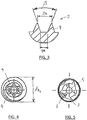
- Fig. 3 shows an enlarged view of the area II according to Fig. 2 in which a profile of the external thread 2 with two adjacent threaded portions of the thread 9 can be seen, which has a thread pitch 2a, which is constant over the axial length of the locking screw 1.
- the external thread further has a flank angle ⁇ , which in the exemplary embodiment is 40 °.
- the threaded portions 9 are spaced apart in the manner of a trapezoidal thread with a distance 9a from each other and have a triangular profile.
- Fig. 2 shows, the locking screw 1 with an axially continuous cannulation 5 with an inner diameter d i provided in the illustrated embodiment, 2.2 mm for receiving a Kirschner wire.
- cutting means 7 In the region of a front, facing away from the drive 4 end 6 of the locking screw 1, this is provided with cutting means 7 in the form of protrusions, so as to obtain a self-tapping and self-drilling locking screw.
- the cutting means 7 comprise three notches extending to the axially front end 6 (FIG. Fig. 5 ), which thereby break turns of the external thread 2.
- the cutting means 7 allow insertion into the bone, without it being necessary to previously cut into this a mating thread, whereby an optimal threaded fit and thus a secure hold of the locking screw 1 is ensured.
Landscapes
- Health & Medical Sciences (AREA)
- Orthopedic Medicine & Surgery (AREA)
- Surgery (AREA)
- Life Sciences & Earth Sciences (AREA)
- Heart & Thoracic Surgery (AREA)
- Nuclear Medicine, Radiotherapy & Molecular Imaging (AREA)
- Engineering & Computer Science (AREA)
- Biomedical Technology (AREA)
- Neurology (AREA)
- Medical Informatics (AREA)
- Molecular Biology (AREA)
- Animal Behavior & Ethology (AREA)
- General Health & Medical Sciences (AREA)
- Public Health (AREA)
- Veterinary Medicine (AREA)
- Surgical Instruments (AREA)
Description
- Die Erfindung betrifft eine chirurgische Arretierschraube gemäß dem Oberbegriff des Anspruchs 1 zum Fixieren von Knochenteilen bei einem Fersenbruch, insbesondere von Knochentrümmern bei einem Fersentrümmerbruch. Die Arretierschraube besteht beispielsweise aus einem metallischen Werkstoff, kann aber ebenso aus einem geeigneten nichtmetallischen Werkstoff bestehen oder einen solchen umfassen.
-
US 2010/094352 A1 ,EP 1 033 111 A1 sowieUS 6 565 566 B1 offenbaren jeweils eine chirurgische Arretierschraube gemäß dem Oberbegriff des Anspruchs 1. - Um eine gute Heilung von Fersenbrüchen zu gewährleisten, ist es notwendig/sinnvoll, die Knochenstücke relativ zueinander zu fixieren, bevor der gesamte Fuß eingegipst wird.
- Der Erfindung liegt die Aufgabe zugrunde, für diesen Zweck geeignete Arretier- bzw. Positioniermittel anzugeben.
- Diese Aufgabe wird mit einer chirurgischen Arretierschraube mit den Merkmalen des Anspruchs 1 gelöst
Der Erfindung liegt der Gedanke zugrunde, eine Arretierschraube zum Fixieren von Knochenteilen bei einem Fersenbruch zur Verfügung zu stellen,welche es ermöglicht, mindestens eine Arretierschraube derart in die gebrochene Ferse einzuschrauben, dass die Arretierschraube möglichst viele Knochenteile unmittelbar kontaktiert bzw. durchsetzt. Um eine rotationsstabile Fixierung der Knochenteile zu ermöglichen, hat es sich bewährt, zwei derartige Arretierschrauben einzusetzen, die zumindest teilweise voneinander beabstandet sind. - Die hier beschriebene Arretierschraube zeichnet sich dadurch aus, dass diese ein zumindest näherungsweise axial durchgehendes, d. h. nicht unterbrochenes Außengewinde aufweist, welches durchgehend eine gleichbleibende Gewindesteigung aufweist, um eine Kompression der Knochenteile zu verhindern. Es hat sich überraschend herausgestellt, dass hierdurch die Heilung nachhaltig verbessert wird. In diesem Zusammenhang bezieht sich die konstante Gewindesteigung auf einen Gewindegang. Das heißt, bei einem mehrgängigen Gewinde ist diese Steigung als der Abstand zweier Gewindespitzen ein und desselben Gewindegangs gegeben.
- Um die Gefahr einer Kompression weiter zu minimieren, ist zusätzlich vorgesehen, dass ein Kerndurchmesser des Außengewindes sowohl in einem unten noch zu erläuternden ersten, distalen, Axialabschnitt als auch in einem in Einschraubrichtung dahinter, also proximal davon, befindlichen zweiten Axialabschnitt konstant ist, obwohl der Außendurchmesser des Außengewindes in dem zweiten (hinteren bzw. antriebsseitgen) Axialabschnitt mit zunehmendem Abstand zum vorderen Ende, das heißt von distal nach proximal, zunimmt. Diese konstruktive Maßnahme dient dazu, trotz eines Verzichtes auf eine Kompression eine definierte Lage der Arretierschraube im Fuß zu gewährleisten, und zwar dahin gehend, dass ein selbsttätiger Vortrieb in der Einschraubrichtung sicher verhindert wird, indem durch den steigenden Außengewindedurchmesser im zweiten Axialabschnitt die Reibung am Ende des Eindrehens in einen zylindrischen Bohrkanal erhöht wird. Gleichzeitig wird durch die erhöhte Reibung der weiter außen liegenden Gewindespitzen ein selbsttätiges Lösen der Schraube verhindert. Der Arretierschraubenkern weist hingegen eine axial durchgehende zylindrische Form auf, ggf. bis auf axial vordere und/oder hintere Anfasungen, die fakultativ vorgesehen sein können.
- Mit anderen Worten zeichnet sich die erfindungsgemäße Arretierschraube trotz Verzichts auf unterschiedliche Gewindesteigungen und auf einen bei Kompressionsschrauben üblichen Durchmesseranstieg des Kerndurchmessers des Außengewindes durch eine Arretier- und Anschlagfunktion aus, die eine definierte Positionierung ermöglicht, wobei die Arretier- und Anschlagsfunktion bei in diesem Axialabschnitt gleichbleibendem Kerndurchmesser durch einen in Richtung Schraubenende ansteigenden Außengewindedurchmesser und eine dadurch vergrößerte Reibung des Gewindes im Knochen realisiert ist. Unter einer Anschlagfunktion im hier benutzten Sinne ist kein fester, formschlüssiger mechanischer Anschlag zu verstehen.
- Vorteilhafte Ausbildungen der Erfindung sind den Unteransprüchen, der Beschreibung und der Zeichnung zu entnehmen.
- Weiterbildungsgemäß ist vorgesehen, dass die Arretierschraube eine axial durchgehende, zentrische Kanülierung (Zentralkanal) zur Aufnahme eines Kirschnerdrahtes aufweist.
- Insbesondere ist der Innendurchmesser der Kanülierung aus einem Wertebereich zwischen etwa 1,0 mm und 3,0 mm gewählt und beträgt in einer Ausführungsform zumindest näherungsweise 2,2 mm. Das weiterbildungsgemäße Vorsehen einer Kanülierung für einen Kirschnerdraht gewährleistet eine optimale, zielgerichtete Einbringbarkeit der chirurgischen Arretierschraube in den menschlichen Fuß.
- Gemäß einer Ausführungsform kann das Außengewinde, wie unten erläutert wird, in einem vorderen Bereich als selbstschneidendes Gewinde ausgebildet sein und/oder in anderweitig ausgestalteten Einschneidmitteln ausmünden.
- Alternativ oder zusätzlich kann das Außengewinde ferner zumindest bereichsweise einen Flankenwinkel aufweisen, der insbesondere zwischen 35° und 45° beträgt, und/oder das Außengewinde kann zumindest bereichsweise trapezförmig ausgebildet sein.
- Im Falle des vorerwähnten Vorsehens einer axial durchgehenden Kanülierung ist der Kernabschnitt bzw. Kernbereich der Schraube hohlzylindrisch ausgebildet. Beispielsweise ist der Kerndurchmesser des Außengewindes - ob kanüliert oder nicht - aus einem Wertebereich zwischen 3,5 mm und 7 mm, insbesondere zwischen 4 mm und 6 mm gewählt. Insbesondere beträgt er zumindest näherungsweise 5 mm. Mit diesen Dimensionen ergeben sich eine gute Handhabbarkeit der Schraube, eine gute Einpassbarkeit in den Knochen bei geringer Schwächung des Knochenmaterials und eine hinreichend große Festigkeit der Schraube,
- Als vorteilhaft hat es sich herausgestellt, wenn derjenige zweite Axialabschnitt, in dem der Außendurchmesser des Außengewindes mit zunehmendem Abstand zum vorderen Ende zunimmt, eine konische Hüllkontur mit einem Öffnungswinkel aufweist, der insbesondere als Kegelvollwinkel zwischen 5° und 6° beträgt.
- Besonders gute Ergebnisse zur Erzielung einer reibungsbedingten Fixierfunktion bei gleichzeitiger Vermeidung einer Kompression werden weiterbildungsgemäß erreicht, wenn ein Außendurchmesserverhältnis eines maximalen Außendurchmessers des zweiten Axialabschnittes zu dem konstanten Außendurchmesser des ersten Axialabschnittes aus einem Wertebereich zwischen 1,0 und 1,4, insbesondere zwischen 1,1 und 1,3 gewählt ist. Insbesondere beträgt das Verhältnis zumindest näherungsweise 1,2. Mit diesen Verhältnissen resultiert eine gute reibungsbedingte Hemmung der Gewindegänge in der Endlage der implantierten Schraube.
- Insbesondere kann der maximale Außendurchmesser des zweiten Axialabschnittes auch dem maximalen Außendurchmesser des Außengewindes insgesamt entsprechen. Insbesondere stellt der maximale Außendurchmesser des zweiten Axialabschnittes den maximalen Durchmesser der Schraube insgesamt dar, d.h. die Schraube umfasst keinen Teil oder Abschnitt, insbesondere keinen Kopf, dessen größter Durchmesser größer als der maximale Außendurchmesser des zweiten Axialabschnittes ist. Insofern kann in dieser Ausführungsform die Schraube als "Madenschraube" bezeichnet werden. Die Schraube weist demnach keinen formschlüssigen mechanischen Anschlag auf, der die Einschraubtiefe der Schraube fest begrenzen würde.
- Der Außendurchmesser des Außengewindes in dem ersten Axialabschnitt ist aus einem Wertebereich zwischen 5,5 mm und 10 mm, insbesondere zwischen 6 mm und 8 mm, gewählt und beträgt insbesondere zumindest näherungsweise 7,5 mm. Weiter ist der maximale Außendurchmesser des Außengewindes im zweiten Axialabschnitt insbesondere aus einem Wertebereich zwischen 7 mm und 12 mm, insbesondere zwischen 8 mm und 11 mm gewählt und beträgt beispielsweise zumindest näherungsweise 9 mm. Mit diesen Dimensionen ergeben sich eine gute Handhabbarkeit der Schraube, eine gute Einpassbarkeit in den Knochen bei geringer Schwächung des Knochenmaterials, eine hinreichend große Festigkeit der Schraube, sowie eine gute reibungsbedingte Hemmung der Gewindegänge in der Endlage der implantierten Schraube.
- Ebenso wirkt es sich positiv auf die Arretierfunktion bzw. die Gewährleistung einer definierten Einbringlage aus, wenn das Längenverhältnis der Gesamtlänge der Arretierschraube zur Länge des, insbesondere eine konische Hüllkontur aufweisenden, zweiten Axialabschnittes aus einem Wertebereich zwischen 2,5 und 5,0, insbesondere zwischen 3,0 und 4,5 gewählt ist.
- Besonders zweckmäßig ist es dabei, wenn die Gesamtlänge der Arretierschraube aus einem Wertebereich zwischen 50 mm und 100 mm, insbesondere zwischen 60 mm und 90 mm gewählt ist und insbesondere 65 mm, 70 mm, 75 mm, 80 mm oder 85 mm beträgt. Die Länge des zweiten Axialabschnittes ist beispielsweise aus einem Wertebereich zwischen 10 mm und 30 mm gewählt und beträgt insbesondere zumindest näherungsweise 20 mm. Die Wahl diese Geometrieparameter vermag die Funktion der Schraube in einer Ausführungsform weiter zu unterstützen.
- Erfindungsgemäß ist am axial hinteren, proximalen Ende der Schraube ein sich beispielsweise über ein bis zwei Gewindegänge erstreckender dritter Außengewindeabschnitt angeordnet, mit gegenüber dem größten Durchmesser des zweiten Axialabschnitts reduziertem Außengewindedurchmesser, wobei der Außengewindedurchmesser in Richtung des hinteren, proximalen, Endes der Schraube insbesondere abnimmt. Diese Verjüngung gewährleistet die Minimierung eines etwaigen Überstandes bzw. eine verbesserte Anpassung an anatomische Gegebenheiten, wodurch der Heilungserfolg verbessert wird. Selbstverständlich kann sich der zweite Axialabschnitt in einer Ausführungsform auch bis zum axial hinteren, proximalen, Ende der Schraube erstrecken.
- Um einen sicheren Halt der Arretierschraube zu gewährleisten, kann vorgesehen sein, dass die Arretierschraube als selbstschneidende Schraube ausgebildet ist, sodass maximal eine Kerndurchmesserbohrung vorgebohrt werden muss und sich das Außengewinde der Arretierschraube selbsttätig in das Gewebe bzw. den Knochen einschraubt. Zu diesem Zweck sind weiterbildungsgemäß Schneidmittel vorgesehen, die insbesondere am vorderen Ende der Schraube angebracht sind, wobei die Schneidmittel zumindest eine sich von radial außen nach radial innen erstreckende Vertiefung umfassen können, die einen Gewindegang unterbricht.
- In einer weiteren Ausführungsform der Arretierschraube ist eine axial vordere, distale, Stirnseite als Fräskopf ausgeführt. Beispielsweise sind eine oder mehrere, beispielsweise drei, sich radial erstreckende oder radial verlaufende und insbesondere axial nach vorne wirkende Schneiden an der distalen Stirnseite der Schraube angeordnet. Dies ermöglicht es, die Schraube selbstbohrend auszuführen, derart, dass sie direkt, d.h. ohne vorzubohren, eingesetzt werden kann. Dabei kann eine kanüllierte Schraube direkt über einen als Führung dienenden Kirschnerdraht implantiert werden.
- Die hintere, proximale, Stirnseite der Schraube ist in einer Ausführungsform mit einem Antrieb und/oder einem Ansatz für ein Werkzeug versehen, beispielsweise einem Innensechskant oder einem Torx-Antrieb.
- Das Außengewinde kann wenigstens einen mehrgängigen Abschnitt mit zwei oder mehr als zwei Gewindegängen aufweisen, wobei insbesondere jeder Gewindegang des mehrgängigen Abschnittes für sich genommen eine konstante Gewindesteigung aufweist. Ferner kann sich der mehrgängige Abschnitt zumindest über einen Bereich der Axialerstreckung des Außengewindes erstrecken, d. h. das Außengewinde muss nicht zwingend über seine gesamte axiale Länge mehrgängig ausgebildet sein. Dabei kann jeder Gewindegang des mehrgängigen Abschnittes eine konstante Gewindesteigung aufweisen.
- Zusammenfassend zeichnet sich die hier beschriebene Arretierschraube unter anderem durch folgende Eigenschaften aus: Durch den zylindrischen Kern und die konstante Gewindesteigung wird eine unerwünschte zusätzliche Kompression auf den Frakturspalt vermieden. Der distale Gewindeabschnitt mit konstantem Außendurchmesser, der sich insbesondere über einen großen Teil der Länge der Arretierschraube erstreckt, ermöglicht eine einfache Implantation, da nur im Bereich des axial vordersten, distalen, Gewindeganges das Gewinde geschnitten werden muss, während der Rest dieses Gewindes mit konstantem Außendurchmesser durch die vorgeschnittenen Gewindegänge gleitet. Gegen Ende der Implantationsphase gelangt der Abschnitt mit dem sich von distal nach proximal vergrößernden Gewindeaußendurchmesser in Eingriff mit dem Knochen. Dieser Gewindeabschnitt muss sich mit weiterem axialem Vorschub stetig neu einschneiden. Dadurch liegen die Gewindespitzen dieses Abschnitts beim Beenden des Einschraubvorgangs stets in frisch verdrängtem Knochenmaterial und sind daher durch eine große Reibungskraft beaufschlagt. Das resultierende Reibungsmoment bewirkt eine sichere Arretierung der Schraube im Knochen.
- In beispielhaften Ausführungsformen kann folgendes vorgesehen sein: Eine Kanülierung ermöglicht die geführte Implantation über einen Kirschnerdraht. Ein Fräskopf an der vorderen, distalen, Stirnseite ermöglicht die Implantation ohne Vorbohren. Selbstschneidende Gewinde ermöglichen die Implantation, ohne im Knochen Gewinde vorzuschneiden. Ein Antrieb an der hinteren, proximalen, Stirnseite ermöglicht eine komfortable Handhabung des Implantats. Die geeignete Wahl bestimmter Geometrieparameter verbessert die Funktion der Arretierschraube weiter.
- Die oben genannten Merkmale können selbstverständlich untereinander kombiniert werden. Weitere Vorteile, Merkmale und Einzelheiten der Erfindung ergeben sich aus der nachfolgenden Beschreibung sowie anhand der Zeichnung.
- Diese zeigt in:
- Fig. 1:
- eine Seitenansicht einer nach dem Konzept der Erfindung ausgebildeten Arretierschraube,
- Fig. 2:
- eine Längsschnittansicht der Arretierschraube gemäß
Fig. 1 , - Fig. 3:
- ein Detail des Außengewindes der Arretierschraube in einem ersten Axialabschnitt.
- Fig. 4:
- eine Ansicht der Arretierschraube von vorne, und
- Fig. 5:
- eine Ansicht der Arretierschraube von hinten.
- In
Fig. 1 ist eine aus Metall, beispielsweise einer Titanlegierung, ausgebildete chirurgische Arretierschraube 1 zur Fixierung von Knochenstücken im Falle eines Fersenbruchs gezeigt. Die Arretierschraube 1 hat keine Kompressionsfunktion, sondern ein axial durchgehendes, hier eingängiges Außengewinde 2 mit einem axial durchgehend gleichbleibenden Kerndurchmesser dK. Die Schraube kann grundsätzlich auch geeignete nichtmetalische Werkstoffe umfassen und/oder aus diesen bestehen. - Die Arretierschraube 1 kann unterteilt werden in einen ersten Axialabschnitt A1 und einen zweiten Axialabschnitt A2. Im ersten Axialabschnitt A1, der durchgängig das Außengewinde 2 aufweist, verändert sich der Außendurchmesser des Außengewindes nicht. Der Außendurchmesser dA1 (
Fig. 2 ) ist also konstant über die Längserstreckung des ersten Axialabschnittes A1 und beträgt in dem gezeigten Ausführungsbeispiel 7,5 mm. - Dahingegen ist ein Außendurchmesser dA2 des Außengewindes 2 im zweiten Axialabschnitt A2 nicht konstant, sondern steigt mit einer konischen Hüllkontur 8 an. Ausgehend von einem Übergang zwischen dem ersten und dem zweiten Axialabschnitt A1, A2, öffnet sich die konische Hüllkontur 8 mit einem Öffnungswinkel α in Richtung eines hinteren Endes 3 der Arretierschraube 1 bis zu einem maximalen Außendurchmesser dA2 des zweiten Axialabschnittes A2, der gleichzeitig dem maximalen Außendurchmesser des Außengewindes 2 und dem maximalen Durchmesser der Schraube 1 insgesamt entspricht (
Fig. 4 ). Im gezeigten Ausführungsbeispiel beträgt der Öffnungswinkel α zwischen 5° und 6° und der maximale Außendurchmesser dA2 9 mm. - Dadurch, dass die Arretierschraube 1 einen axial durchgehend gleichbleibenden Kerndurchmesser dK und gleichzeitig in dem zweiten Axialabschnitt A2 einen nach hinten zunehmenden Außendurchmesser des Außengewindes 2 aufweist, wird eine sichere Positionierung der Arretierschraube 1 in der menschlichen Ferse ermöglicht, ohne dass es zu einer Kompression der Knochenteile kommt.
- Das hintere, proximale, Ende 3 der Arretierschraube 1 wird von einem sich an den zweiten Axialabschnitt A2 anschließenden, vergleichsweise kurzen Außendurchmesserabschnitt A3 gebildet, der sich über etwa 1,5 Gewindegänge erstreckt, in denen der Außengewindedurchmesser des Außengewindes 2 nach hinten wieder abnimmt.
-
Fig. 3 zeigt eine vergrößerte Ansicht des Bereichs II gemäßFig 2 , in der ein Profil des Außengewindes 2 mit zwei benachbarten Gewindeabschnitten des Gewindeganges 9 erkennbar ist, der eine Gewindesteigung 2a besitzt, die über die axiale Länge der Arretierschraube 1 konstant ist. Das Außengewinde weist ferner einen Flankenwinkel β auf, der im Ausführungsbeispiel 40° beträgt. Die Gewindeabschnitte 9 sind in der Weise eines Trapezgewindes mit einem Abstand 9a voneinander beabstandet und weisen ein dreieckiges Profil auf. - Im hinteren Ende 3 der Arretierschraube 1 ist ein als Torxantrieb ausgebildeter Antrieb 4 eingebracht (
Fig. 4 ). - Wie sich insbesondere aus
Fig. 2 ergibt, ist die Arretierschraube 1 mit einer axial durchgehenden Kanülierung 5 mit einem Innendurchmesser di von in dem gezeigten Ausführungsbeispiel 2,2 mm zur Aufnahme eines Kirschnerdrahtes versehen. - Im Bereich eines vorderen, von dem Antrieb 4 abgewandten Endes 6 der Arretierschraube 1 ist diese mit Schneidmitteln 7 in der Form von Ausbuchtungen versehen, um somit eine selbstschneidende und selbstbohrende Arretierschraube zu erhalten. Die Schneidmittel 7 umfassen drei bis zum axial vorderen Ende 6 reichende Einkerbungen (
Fig. 5 ), die dabei Windungen des Außengewindes 2 unterbrechen. Es sind drei radial verlaufende und axial wirkende Schneidkanten an der distalen Stirnseite der Schraube angeordnet. Im gezeigten Ausführungsbeispiel beträgt eine axiale Länge der Schneidmittel 7 3 mm. - Die Schneidmittel 7 ermöglichen eine Einbringung in den Knochen, ohne dass es notwendig ist, zuvor in diesen ein Gegengewinde einzuschneiden, wodurch eine optimale Gewindepassung und damit ein sicherer Halt der Arretierschraube 1 sichergestellt wird.
-
- 1
- Arretierschraube
- 2
- Außengewinde
- 2a
- Gewindesteigung
- 3
- hinteres Ende
- 4
- Antrieb
- 5
- Kanülierung
- 6
- vorderes Ende
- 7
- Schneidmittel
- 8
- konische Hüllkontur
- 9
- Gewindegang
- 9a
- Abstand
- A1
- erster Axialabschnitt
- A2
- zweiter Axialabschnitt
- A3
- hinterer Außengewindeabschnitt
- dA1
- Außendurchmesser im ersten Axialabschnitt
- dA2
- Außendurchmesser im zweiten Axialabschnitt
- di
- Innendurchmesser der Kanülierung
- dK
- Kerndurchmesser
Claims (12)
- Chirurgische Arretierschraube zum Fixieren von Knochenteilen bei einem Fersenbruch, mit einem vorderen Ende (6), mit einem einen Antrieb (4) zum Verdrehen der Arretierschraube (1) aufweisenden hinteren Antriebsende und mit einem Außengewinde (2), welches über seine Axialerstreckung durchgehend eine gleichbleibende Gewindesteigung aufweist, wobei ein Außendurchmesser (dA1) des Außengewindes (2) in einem ersten Axialabschnitt (A1) der Arretierschraube (1) konstant ist und in einem zu dem ersten Axialabschnitt (A1) in Richtung des hinteren Endes (3) benachbarten zweiten Axialabschnitt (A2) mit zunehmendem Abstand zu dem vorderen Ende (6) zunimmt,wobei ein Kerndurchmesser (dK) des Außengewindes (2) im ersten und zweiten Axialabschnitt (A1, A2) konstant ist,wobei das Außengewinde (2) sich axial durchgehend über die gesamte Axialerstreckung der Arretierschraube erstreckt, undwobei sich der Kerndurchmesser (dK) des Außengewindes (2) über die gesamte Axialerstreckung des Außengewindes (2) erstreckt,dadurch gekennzeichnet,dass axial nach hinten anschließend an den zweiten Axialabschnitt (A2) ein, sich insbesondere über ein bis zwei Gewindegänge erstreckender, dritter Außengewindeendabschnitt (A3) mit gegenüber dem größten Außendurchmesser (dA2) des zweiten Axialabschnittes reduziertem Außengewindedurchmesser vorgesehen ist.
- Arretierschraube nach Anspruch 1,
dadurch gekennzeichnet,
dass die Arretierschraube (1) eine axial durchgehende, zentrische Kanülierung (5) zur Aufnahme eines Kirschnerdrahtes aufweist. - Arretierschraube nach Anspruch 1 oder 2,
dadurch gekennzeichnet,
dass der zweite Axialabschnitt (A2) eine konische Hüllkontur (8) aufweist. - Arretierschraube nach einem der vorhergehenden Ansprüche,
dadurch gekennzeichnet,
dass ein Außendurchmesserverhältnis eines maximalen Außendurchmessers (dA2) des zweiten Axialabschnittes zu dem konstanten Außendurchmesser (dA1) des ersten Axialabschnittes aus einem Wertebereich zwischen 1,05 und 1,4, insbesondere zwischen 1,1 und 1,3 gewählt ist und/oder 1,2 beträgt. - Arretierschraube nach einem der vorhergehenden Ansprüche,
dadurch gekennzeichnet,
dass ein Längenverhältnis der Gesamtlänge der Arretierschraube (1) zur Länge des zweiten Axialabschnittes (A2) aus einem Wertebereich zwischen 2,5 und 5,0, insbesondere zwischen 3,0 und 4,5 gewählt ist. - Arretierschraube nach einem der vorhergehenden Ansprüche,
dadurch gekennzeichnet,
dass die Länge des zweiten Axialabschnittes (A2) aus einem Wertebereich zwischen 10 mm und 30 mm gewählt ist und/oder 20 mm beträgt. - Arretierschraube nach einem der vorhergehenden Ansprüche,
dadurch gekennzeichnet,
dass die Arretierschraube (1) als selbstschneidende Schraube mit, insbesondere am vorderen Ende (6) vorgesehenen Schneidmitteln (7) ausgebildet ist. - Arretierschraube nach einem der vorhergehenden Ansprüche,
dadurch gekennzeichnet,
dass das Außengewinde (2) wenigstens einen mehrgängigen Abschnitt mit zwei oder mehr als zwei Gewindegängen aufweist, der sich zumindest über einen Bereich der Axialerstreckung des Außengewindes (2) erstreckt. - Arretierschraube nach Anspruch 8,
dadurch gekennzeichnet,
dass die mehreren Gewindegängen des mehrgängigen Abschnittes jeweils eine konstante Gewindesteigung aufweisen. - Arretierschraube nach einem der vorhergehenden Ansprüche,
dadurch gekennzeichnet,
dass ein maximaler Außendurchmessers (dA2) des zweiten Axialabschnittes (A2) dem maximalen Außendurchmesser des Außengewindes (2) entspricht. - Arretierschraube nach einem der vorhergehenden Ansprüche,
dadurch gekennzeichnet,
dass das Außengewinde (2) zumindest über einen Bereich der Axialerstreckung einen Flankenwinkel (β) umfasst, der insbesondere zwischen 35° und 45° beträgt. - Arretierschraube nach einem der vorhergehenden Ansprüche,
dadurch gekennzeichnet,
dass das Außengewinde (2) zumindest über einen Bereich der Axialerstreckung trapezförmig ausgebildet ist.
Applications Claiming Priority (2)
| Application Number | Priority Date | Filing Date | Title |
|---|---|---|---|
| DE202013101135.5U DE202013101135U1 (de) | 2013-03-15 | 2013-03-15 | Chirurgische Arretierschraube |
| PCT/EP2014/055256 WO2014140360A1 (de) | 2013-03-15 | 2014-03-17 | Chirurgische arretierschraube |
Publications (2)
| Publication Number | Publication Date |
|---|---|
| EP2948083A1 EP2948083A1 (de) | 2015-12-02 |
| EP2948083B1 true EP2948083B1 (de) | 2017-08-16 |
Family
ID=50342300
Family Applications (1)
| Application Number | Title | Priority Date | Filing Date |
|---|---|---|---|
| EP14711483.9A Active EP2948083B1 (de) | 2013-03-15 | 2014-03-17 | Chirurgische arretierschraube |
Country Status (4)
| Country | Link |
|---|---|
| US (1) | US9993275B2 (de) |
| EP (1) | EP2948083B1 (de) |
| DE (1) | DE202013101135U1 (de) |
| WO (1) | WO2014140360A1 (de) |
Families Citing this family (20)
| Publication number | Priority date | Publication date | Assignee | Title |
|---|---|---|---|---|
| EP2872073B1 (de) | 2012-07-12 | 2018-09-19 | Exsomed Holding Company LLC | Mittelhandknochenstabilisiereinrichtung |
| DE202013101135U1 (de) | 2013-03-15 | 2014-06-17 | Zimmer Gmbh | Chirurgische Arretierschraube |
| US11259849B2 (en) | 2013-10-02 | 2022-03-01 | ExsoMed Corporation | Full wrist fusion device |
| WO2016186847A1 (en) | 2015-05-19 | 2016-11-24 | Exsomed International IP, LLC | Distal radius plate |
| US10245091B2 (en) | 2015-12-30 | 2019-04-02 | Exsomed Holding Company, Llc | Dip fusion spike screw |
| US11147604B2 (en) * | 2016-01-12 | 2021-10-19 | ExsoMed Corporation | Bone stabilization device |
| US10194923B2 (en) | 2016-05-10 | 2019-02-05 | Exsomed International IP, LLC | Tool for percutaneous joint cartilage destruction and preparation for joint fusion |
| US9655661B1 (en) * | 2016-06-30 | 2017-05-23 | Hugh Boyd Watts | Cannulated orthopedic screw and method of reducing and fixing a fracture of the lateral malleolus |
| US11376050B2 (en) * | 2017-06-27 | 2022-07-05 | Medos International Sarl | Bone screw |
| US11147681B2 (en) | 2017-09-05 | 2021-10-19 | ExsoMed Corporation | Small bone angled compression screw |
| US11191645B2 (en) | 2017-09-05 | 2021-12-07 | ExsoMed Corporation | Small bone tapered compression screw |
| EP4477166A3 (de) * | 2017-09-05 | 2025-03-19 | ExsoMed Corporation | Gewindemarknagel zur radialen kortikalisfixierung |
| CN113473918B (zh) * | 2018-09-14 | 2024-10-01 | 博恩医疗器械股份有限公司 | 整形骨螺钉 |
| US11266453B2 (en) * | 2018-09-21 | 2022-03-08 | DePuy Synthes Products, Inc. | Bone compression screws and related systems and methods |
| RU2706140C1 (ru) * | 2019-02-19 | 2019-11-14 | Государственное бюджетное учреждение Санкт-Петербургский научно-исследовательский институт скорой помощи им. И.И. Джанелидзе Российской Федерации | Канюлированный винт для малоинвазивного остеосинтеза нестабильных повреждений тазового кольца |
| US11564720B2 (en) * | 2020-03-11 | 2023-01-31 | Acumed Llc | Intramedullary stabilization screw |
| TWI763162B (zh) * | 2020-12-04 | 2022-05-01 | 鐿鈦科技股份有限公司 | 縫合錨釘與其系統及植入方法 |
| RU2756428C1 (ru) * | 2020-12-09 | 2021-09-30 | Александр Иванович Колесник | Устройство для открытой репозиции смещенных колонн вертлужной впадины |
| AU2023384252A1 (en) | 2022-11-22 | 2025-07-03 | Voom Medical Devices, Inc. | Orthopedic bone screw |
| US11832864B1 (en) | 2023-04-12 | 2023-12-05 | OC Medical Devices, LLC | Orthopedic implants and tools |
Family Cites Families (30)
| Publication number | Priority date | Publication date | Assignee | Title |
|---|---|---|---|---|
| DE8900121U1 (de) * | 1989-01-04 | 1990-02-15 | Mecron Medizinische Produkte Gmbh, 1000 Berlin | Vorrichtung zur Kompressionsverschraubung |
| IT1237496B (it) * | 1989-10-26 | 1993-06-08 | Giuseppe Vrespa | Dispositivo a vite per l'ancoraggio di protesi alle ossa, metodo per l'applicazione di tale dispositivo e relativa attrezzatura |
| ES2077423T3 (es) * | 1991-06-25 | 1995-11-16 | Synthes Ag | Elemento de fijacion. |
| USD356868S (en) * | 1992-10-28 | 1995-03-28 | Aktiebolaget Astra | Single tooth fixture for use in oral implantology |
| US5443509A (en) * | 1992-12-10 | 1995-08-22 | Linvatec Corporation | Interference bone-fixation screw with multiple interleaved threads |
| US6984235B2 (en) | 1993-01-21 | 2006-01-10 | Acumed Llc | System for fusing joints |
| US6030162A (en) * | 1998-12-18 | 2000-02-29 | Acumed, Inc. | Axial tension screw |
| US5601553A (en) * | 1994-10-03 | 1997-02-11 | Synthes (U.S.A.) | Locking plate and bone screw |
| US5827031A (en) * | 1997-05-14 | 1998-10-27 | Swallow; Gregory T. | Self starting finishing screw and driver tool |
| EP1033111B1 (de) | 1999-03-01 | 2004-05-06 | Centerpulse Orthopedics Ltd. | Knochenschraube zur Verankerung eines Marknagels |
| US6565566B1 (en) | 2000-03-22 | 2003-05-20 | Spinal Concepts, Inc. | Sacral screw assembly and method |
| US6635059B2 (en) * | 2001-01-03 | 2003-10-21 | Bernard L. Randall | Cannulated locking screw system especially for transiliac implant |
| US8518090B2 (en) | 2010-10-05 | 2013-08-27 | Acumed Llc | Fastener with serrated thread for attachment to a bone plate at a selectable angle |
| CA2390912C (en) * | 2001-07-05 | 2008-01-29 | Depuy France | Self-tapping screw for small-bone surgery |
| SE0102749D0 (sv) * | 2001-08-15 | 2001-08-15 | Astra Tech Ab | Implant, arrangement comprising an implant, and method for inserting said implant in bone tissue |
| EP1594411A4 (de) * | 2003-02-03 | 2010-07-07 | Integra Lifesciences Corp | Kompressionsschraubengeräte, systeme und methoden |
| US20050131413A1 (en) * | 2003-06-20 | 2005-06-16 | O'driscoll Shawn W. | Bone plate with interference fit screw |
| US7799062B2 (en) * | 2004-11-30 | 2010-09-21 | Stryker Trauma S.A. | Self-guiding threaded fastener |
| FR2902637B1 (fr) * | 2006-06-22 | 2009-03-20 | T H T Textile Hi Tec Sa | Ensemble chirurgical pour la reparation osseuse comprenant une vis cylindrique du type vis de herbert |
| US20080027444A1 (en) * | 2006-07-28 | 2008-01-31 | Malek Michel H | Bone anchor device |
| EP2299915B1 (de) * | 2008-06-16 | 2018-07-18 | Cayenne Medical, Inc. | Anker zur verankerung von nahtmaterial an knochen |
| FR2932975B1 (fr) | 2008-06-26 | 2011-09-02 | Fournitures Hospitalieres Ind | Vis d'osteosynthese |
| US20100094352A1 (en) | 2008-10-10 | 2010-04-15 | Andrew Iott | Bone screw |
| ATE507785T1 (de) * | 2009-02-16 | 2011-05-15 | Stryker Trauma Ag | Knochenschraube und herstellungsverfahren hierfür |
| US8574273B2 (en) * | 2009-09-09 | 2013-11-05 | Innovision, Inc. | Bone screws and methods of use thereof |
| US9592084B2 (en) * | 2010-08-27 | 2017-03-14 | William P. Grant | Foot beam insert |
| US20120178048A1 (en) * | 2011-01-11 | 2012-07-12 | Cottrell Richard D | Dental implant with multiple thread patterns |
| WO2012103354A1 (en) | 2011-01-26 | 2012-08-02 | Del Palma Orthopedics, LLC | Upper extremity fusion devices |
| US8998550B2 (en) * | 2013-02-11 | 2015-04-07 | James Michael Platt | Hardware attachment system |
| DE202013101135U1 (de) | 2013-03-15 | 2014-06-17 | Zimmer Gmbh | Chirurgische Arretierschraube |
-
2013
- 2013-03-15 DE DE202013101135.5U patent/DE202013101135U1/de not_active Expired - Lifetime
-
2014
- 2014-03-17 EP EP14711483.9A patent/EP2948083B1/de active Active
- 2014-03-17 US US14/776,011 patent/US9993275B2/en not_active Expired - Fee Related
- 2014-03-17 WO PCT/EP2014/055256 patent/WO2014140360A1/de not_active Ceased
Non-Patent Citations (1)
| Title |
|---|
| None * |
Also Published As
| Publication number | Publication date |
|---|---|
| EP2948083A1 (de) | 2015-12-02 |
| US9993275B2 (en) | 2018-06-12 |
| DE202013101135U1 (de) | 2014-06-17 |
| WO2014140360A1 (de) | 2014-09-18 |
| US20160030097A1 (en) | 2016-02-04 |
Similar Documents
| Publication | Publication Date | Title |
|---|---|---|
| WO2014140360A1 (de) | Chirurgische arretierschraube | |
| EP1524948B1 (de) | Dentalimplantat mit verankerungskopf und schraubkörper | |
| EP0172130B1 (de) | Schraube zur orthopädischen Fixation | |
| DE69415676T2 (de) | Sperrklinken-kompressionseinrichtung | |
| EP2218415B1 (de) | Knochenschraube und Herstellungsverfahren hierfür | |
| EP2564799B1 (de) | Chirurgischer Mittelfuß-Kompressionsnagel | |
| DE60226248T3 (de) | Knochenimplantat | |
| EP1096892B1 (de) | Knochenschraube, insbesondere für den einsatz bei translaminärer wirbelverschraubung | |
| EP1940306B1 (de) | Gewindeformende schraube | |
| DE60206216T2 (de) | Selbstschneidende Schraube zur Chirurgie kleiner Knochen | |
| EP0682917B1 (de) | Schraubwerkzeug für eine Schraube, bestehend aus einem Bolzenteil und einer darauf aufschraubbaren Mutter | |
| EP0513943A1 (de) | Implantat mit Pressfläche | |
| EP3640487A1 (de) | Holzschraube mit bogenförmigem überstand zwischen gewindegängen | |
| EP3082628A1 (de) | Selbstbohrende spannungsabsorbierende knochenschraube | |
| DE202012002636U1 (de) | Schraubenimplantat für einen Kieferknochen mit koronalem Kompressionsgewinde und apikalem Selbstschneidgewinde | |
| EP0841875B1 (de) | Bohrkopf zum aufbohren von knochenkanälen | |
| EP1096891B1 (de) | Knochenschraube | |
| DE69636933T2 (de) | Zahnimplantat mit selbstschneidendem gewinde | |
| EP3726072B1 (de) | Schraube für holzwerkstoffe | |
| EP1795148B1 (de) | Dentalimplantat | |
| DE10238091A1 (de) | Dentalimplantat mit Verankerungskopf und Schraubkörper | |
| EP2029037B1 (de) | Femurkopf-implantat | |
| EP3742993B1 (de) | Intravertebrale schraube | |
| EP1033111B1 (de) | Knochenschraube zur Verankerung eines Marknagels | |
| EP3912590A1 (de) | Dentalimplantat aus einem metall oder einer metalllegierung |
Legal Events
| Date | Code | Title | Description |
|---|---|---|---|
| PUAI | Public reference made under article 153(3) epc to a published international application that has entered the european phase |
Free format text: ORIGINAL CODE: 0009012 |
|
| 17P | Request for examination filed |
Effective date: 20150826 |
|
| AK | Designated contracting states |
Kind code of ref document: A1 Designated state(s): AL AT BE BG CH CY CZ DE DK EE ES FI FR GB GR HR HU IE IS IT LI LT LU LV MC MK MT NL NO PL PT RO RS SE SI SK SM TR |
|
| AX | Request for extension of the european patent |
Extension state: BA ME |
|
| DAX | Request for extension of the european patent (deleted) | ||
| GRAP | Despatch of communication of intention to grant a patent |
Free format text: ORIGINAL CODE: EPIDOSNIGR1 |
|
| STAA | Information on the status of an ep patent application or granted ep patent |
Free format text: STATUS: GRANT OF PATENT IS INTENDED |
|
| INTG | Intention to grant announced |
Effective date: 20170314 |
|
| RIN1 | Information on inventor provided before grant (corrected) |
Inventor name: KOTULJAC, VLADKO Inventor name: MILDNER, ALEXANDER |
|
| GRAS | Grant fee paid |
Free format text: ORIGINAL CODE: EPIDOSNIGR3 |
|
| GRAA | (expected) grant |
Free format text: ORIGINAL CODE: 0009210 |
|
| STAA | Information on the status of an ep patent application or granted ep patent |
Free format text: STATUS: THE PATENT HAS BEEN GRANTED |
|
| AK | Designated contracting states |
Kind code of ref document: B1 Designated state(s): AL AT BE BG CH CY CZ DE DK EE ES FI FR GB GR HR HU IE IS IT LI LT LU LV MC MK MT NL NO PL PT RO RS SE SI SK SM TR |
|
| REG | Reference to a national code |
Ref country code: GB Ref legal event code: FG4D Free format text: NOT ENGLISH |
|
| REG | Reference to a national code |
Ref country code: CH Ref legal event code: EP Ref country code: CH Ref legal event code: NV Representative=s name: DR. GRAF AND PARTNER AG INTELLECTUAL PROPERTY, CH |
|
| REG | Reference to a national code |
Ref country code: IE Ref legal event code: FG4D Free format text: LANGUAGE OF EP DOCUMENT: GERMAN |
|
| REG | Reference to a national code |
Ref country code: AT Ref legal event code: REF Ref document number: 918320 Country of ref document: AT Kind code of ref document: T Effective date: 20170915 |
|
| REG | Reference to a national code |
Ref country code: DE Ref legal event code: R096 Ref document number: 502014005055 Country of ref document: DE |
|
| REG | Reference to a national code |
Ref country code: NL Ref legal event code: MP Effective date: 20170816 |
|
| REG | Reference to a national code |
Ref country code: LT Ref legal event code: MG4D |
|
| PG25 | Lapsed in a contracting state [announced via postgrant information from national office to epo] |
Ref country code: LT Free format text: LAPSE BECAUSE OF FAILURE TO SUBMIT A TRANSLATION OF THE DESCRIPTION OR TO PAY THE FEE WITHIN THE PRESCRIBED TIME-LIMIT Effective date: 20170816 Ref country code: FI Free format text: LAPSE BECAUSE OF FAILURE TO SUBMIT A TRANSLATION OF THE DESCRIPTION OR TO PAY THE FEE WITHIN THE PRESCRIBED TIME-LIMIT Effective date: 20170816 Ref country code: NO Free format text: LAPSE BECAUSE OF FAILURE TO SUBMIT A TRANSLATION OF THE DESCRIPTION OR TO PAY THE FEE WITHIN THE PRESCRIBED TIME-LIMIT Effective date: 20171116 Ref country code: SE Free format text: LAPSE BECAUSE OF FAILURE TO SUBMIT A TRANSLATION OF THE DESCRIPTION OR TO PAY THE FEE WITHIN THE PRESCRIBED TIME-LIMIT Effective date: 20170816 Ref country code: NL Free format text: LAPSE BECAUSE OF FAILURE TO SUBMIT A TRANSLATION OF THE DESCRIPTION OR TO PAY THE FEE WITHIN THE PRESCRIBED TIME-LIMIT Effective date: 20170816 |
|
| REG | Reference to a national code |
Ref country code: FR Ref legal event code: PLFP Year of fee payment: 5 |
|
| PG25 | Lapsed in a contracting state [announced via postgrant information from national office to epo] |
Ref country code: LV Free format text: LAPSE BECAUSE OF FAILURE TO SUBMIT A TRANSLATION OF THE DESCRIPTION OR TO PAY THE FEE WITHIN THE PRESCRIBED TIME-LIMIT Effective date: 20170816 Ref country code: GR Free format text: LAPSE BECAUSE OF FAILURE TO SUBMIT A TRANSLATION OF THE DESCRIPTION OR TO PAY THE FEE WITHIN THE PRESCRIBED TIME-LIMIT Effective date: 20171117 Ref country code: PL Free format text: LAPSE BECAUSE OF FAILURE TO SUBMIT A TRANSLATION OF THE DESCRIPTION OR TO PAY THE FEE WITHIN THE PRESCRIBED TIME-LIMIT Effective date: 20170816 Ref country code: ES Free format text: LAPSE BECAUSE OF FAILURE TO SUBMIT A TRANSLATION OF THE DESCRIPTION OR TO PAY THE FEE WITHIN THE PRESCRIBED TIME-LIMIT Effective date: 20170816 Ref country code: IS Free format text: LAPSE BECAUSE OF FAILURE TO SUBMIT A TRANSLATION OF THE DESCRIPTION OR TO PAY THE FEE WITHIN THE PRESCRIBED TIME-LIMIT Effective date: 20171216 Ref country code: BG Free format text: LAPSE BECAUSE OF FAILURE TO SUBMIT A TRANSLATION OF THE DESCRIPTION OR TO PAY THE FEE WITHIN THE PRESCRIBED TIME-LIMIT Effective date: 20171116 Ref country code: RS Free format text: LAPSE BECAUSE OF FAILURE TO SUBMIT A TRANSLATION OF THE DESCRIPTION OR TO PAY THE FEE WITHIN THE PRESCRIBED TIME-LIMIT Effective date: 20170816 |
|
| PG25 | Lapsed in a contracting state [announced via postgrant information from national office to epo] |
Ref country code: DK Free format text: LAPSE BECAUSE OF FAILURE TO SUBMIT A TRANSLATION OF THE DESCRIPTION OR TO PAY THE FEE WITHIN THE PRESCRIBED TIME-LIMIT Effective date: 20170816 Ref country code: RO Free format text: LAPSE BECAUSE OF FAILURE TO SUBMIT A TRANSLATION OF THE DESCRIPTION OR TO PAY THE FEE WITHIN THE PRESCRIBED TIME-LIMIT Effective date: 20170816 Ref country code: CZ Free format text: LAPSE BECAUSE OF FAILURE TO SUBMIT A TRANSLATION OF THE DESCRIPTION OR TO PAY THE FEE WITHIN THE PRESCRIBED TIME-LIMIT Effective date: 20170816 |
|
| REG | Reference to a national code |
Ref country code: DE Ref legal event code: R097 Ref document number: 502014005055 Country of ref document: DE |
|
| PG25 | Lapsed in a contracting state [announced via postgrant information from national office to epo] |
Ref country code: SM Free format text: LAPSE BECAUSE OF FAILURE TO SUBMIT A TRANSLATION OF THE DESCRIPTION OR TO PAY THE FEE WITHIN THE PRESCRIBED TIME-LIMIT Effective date: 20170816 Ref country code: SK Free format text: LAPSE BECAUSE OF FAILURE TO SUBMIT A TRANSLATION OF THE DESCRIPTION OR TO PAY THE FEE WITHIN THE PRESCRIBED TIME-LIMIT Effective date: 20170816 Ref country code: EE Free format text: LAPSE BECAUSE OF FAILURE TO SUBMIT A TRANSLATION OF THE DESCRIPTION OR TO PAY THE FEE WITHIN THE PRESCRIBED TIME-LIMIT Effective date: 20170816 |
|
| PLBE | No opposition filed within time limit |
Free format text: ORIGINAL CODE: 0009261 |
|
| STAA | Information on the status of an ep patent application or granted ep patent |
Free format text: STATUS: NO OPPOSITION FILED WITHIN TIME LIMIT |
|
| 26N | No opposition filed |
Effective date: 20180517 |
|
| PG25 | Lapsed in a contracting state [announced via postgrant information from national office to epo] |
Ref country code: SI Free format text: LAPSE BECAUSE OF FAILURE TO SUBMIT A TRANSLATION OF THE DESCRIPTION OR TO PAY THE FEE WITHIN THE PRESCRIBED TIME-LIMIT Effective date: 20170816 |
|
| PG25 | Lapsed in a contracting state [announced via postgrant information from national office to epo] |
Ref country code: MT Free format text: LAPSE BECAUSE OF FAILURE TO SUBMIT A TRANSLATION OF THE DESCRIPTION OR TO PAY THE FEE WITHIN THE PRESCRIBED TIME-LIMIT Effective date: 20170816 |
|
| PG25 | Lapsed in a contracting state [announced via postgrant information from national office to epo] |
Ref country code: MC Free format text: LAPSE BECAUSE OF FAILURE TO SUBMIT A TRANSLATION OF THE DESCRIPTION OR TO PAY THE FEE WITHIN THE PRESCRIBED TIME-LIMIT Effective date: 20170816 |
|
| REG | Reference to a national code |
Ref country code: BE Ref legal event code: MM Effective date: 20180331 |
|
| PG25 | Lapsed in a contracting state [announced via postgrant information from national office to epo] |
Ref country code: LU Free format text: LAPSE BECAUSE OF NON-PAYMENT OF DUE FEES Effective date: 20180317 |
|
| PG25 | Lapsed in a contracting state [announced via postgrant information from national office to epo] |
Ref country code: BE Free format text: LAPSE BECAUSE OF NON-PAYMENT OF DUE FEES Effective date: 20180331 |
|
| PG25 | Lapsed in a contracting state [announced via postgrant information from national office to epo] |
Ref country code: TR Free format text: LAPSE BECAUSE OF FAILURE TO SUBMIT A TRANSLATION OF THE DESCRIPTION OR TO PAY THE FEE WITHIN THE PRESCRIBED TIME-LIMIT Effective date: 20170816 |
|
| PG25 | Lapsed in a contracting state [announced via postgrant information from national office to epo] |
Ref country code: PT Free format text: LAPSE BECAUSE OF FAILURE TO SUBMIT A TRANSLATION OF THE DESCRIPTION OR TO PAY THE FEE WITHIN THE PRESCRIBED TIME-LIMIT Effective date: 20170816 |
|
| PG25 | Lapsed in a contracting state [announced via postgrant information from national office to epo] |
Ref country code: HR Free format text: LAPSE BECAUSE OF FAILURE TO SUBMIT A TRANSLATION OF THE DESCRIPTION OR TO PAY THE FEE WITHIN THE PRESCRIBED TIME-LIMIT Effective date: 20170816 Ref country code: HU Free format text: LAPSE BECAUSE OF FAILURE TO SUBMIT A TRANSLATION OF THE DESCRIPTION OR TO PAY THE FEE WITHIN THE PRESCRIBED TIME-LIMIT; INVALID AB INITIO Effective date: 20140317 Ref country code: MK Free format text: LAPSE BECAUSE OF NON-PAYMENT OF DUE FEES Effective date: 20170816 Ref country code: CY Free format text: LAPSE BECAUSE OF FAILURE TO SUBMIT A TRANSLATION OF THE DESCRIPTION OR TO PAY THE FEE WITHIN THE PRESCRIBED TIME-LIMIT Effective date: 20170816 |
|
| PG25 | Lapsed in a contracting state [announced via postgrant information from national office to epo] |
Ref country code: AL Free format text: LAPSE BECAUSE OF FAILURE TO SUBMIT A TRANSLATION OF THE DESCRIPTION OR TO PAY THE FEE WITHIN THE PRESCRIBED TIME-LIMIT Effective date: 20170816 |
|
| REG | Reference to a national code |
Ref country code: AT Ref legal event code: MM01 Ref document number: 918320 Country of ref document: AT Kind code of ref document: T Effective date: 20190317 |
|
| PG25 | Lapsed in a contracting state [announced via postgrant information from national office to epo] |
Ref country code: AT Free format text: LAPSE BECAUSE OF NON-PAYMENT OF DUE FEES Effective date: 20190317 |
|
| P01 | Opt-out of the competence of the unified patent court (upc) registered |
Effective date: 20230525 |
|
| PGFP | Annual fee paid to national office [announced via postgrant information from national office to epo] |
Ref country code: CH Payment date: 20250401 Year of fee payment: 12 |
|
| REG | Reference to a national code |
Ref country code: CH Ref legal event code: U11 Free format text: ST27 STATUS EVENT CODE: U-0-0-U10-U11 (AS PROVIDED BY THE NATIONAL OFFICE) Effective date: 20260401 |
|
| PGFP | Annual fee paid to national office [announced via postgrant information from national office to epo] |
Ref country code: GB Payment date: 20260213 Year of fee payment: 13 |
|
| PGFP | Annual fee paid to national office [announced via postgrant information from national office to epo] |
Ref country code: DE Payment date: 20260216 Year of fee payment: 13 Ref country code: IE Payment date: 20260203 Year of fee payment: 13 |
|
| PGFP | Annual fee paid to national office [announced via postgrant information from national office to epo] |
Ref country code: IT Payment date: 20260127 Year of fee payment: 13 |
|
| PGFP | Annual fee paid to national office [announced via postgrant information from national office to epo] |
Ref country code: FR Payment date: 20260212 Year of fee payment: 13 |