EP2948040B1 - Visual electrophysiology device - Google Patents
Visual electrophysiology device Download PDFInfo
- Publication number
- EP2948040B1 EP2948040B1 EP14743566.3A EP14743566A EP2948040B1 EP 2948040 B1 EP2948040 B1 EP 2948040B1 EP 14743566 A EP14743566 A EP 14743566A EP 2948040 B1 EP2948040 B1 EP 2948040B1
- Authority
- EP
- European Patent Office
- Prior art keywords
- light
- flash
- eye
- stimulus
- light emitter
- Prior art date
- Legal status (The legal status is an assumption and is not a legal conclusion. Google has not performed a legal analysis and makes no representation as to the accuracy of the status listed.)
- Active
Links
- 230000000007 visual effect Effects 0.000 title claims description 56
- 238000002001 electrophysiology Methods 0.000 title description 16
- 230000007831 electrophysiology Effects 0.000 title description 16
- 210000001747 pupil Anatomy 0.000 claims description 71
- 238000000034 method Methods 0.000 claims description 42
- 238000000295 emission spectrum Methods 0.000 claims description 23
- 230000002207 retinal effect Effects 0.000 claims description 18
- 230000003287 optical effect Effects 0.000 claims description 15
- 230000000737 periodic effect Effects 0.000 claims description 13
- 230000004044 response Effects 0.000 claims description 13
- 238000004458 analytical method Methods 0.000 claims description 5
- 238000012544 monitoring process Methods 0.000 claims description 3
- 230000006870 function Effects 0.000 description 31
- 238000005286 illumination Methods 0.000 description 12
- 238000005259 measurement Methods 0.000 description 12
- 238000012360 testing method Methods 0.000 description 9
- 230000000638 stimulation Effects 0.000 description 7
- 210000001525 retina Anatomy 0.000 description 6
- 230000003595 spectral effect Effects 0.000 description 6
- 230000000694 effects Effects 0.000 description 5
- 238000001228 spectrum Methods 0.000 description 5
- 230000008901 benefit Effects 0.000 description 4
- 230000001276 controlling effect Effects 0.000 description 4
- 238000010586 diagram Methods 0.000 description 4
- 230000004075 alteration Effects 0.000 description 3
- 201000010099 disease Diseases 0.000 description 3
- 208000037265 diseases, disorders, signs and symptoms Diseases 0.000 description 3
- 208000032253 retinal ischemia Diseases 0.000 description 3
- 230000004936 stimulating effect Effects 0.000 description 3
- 206010012689 Diabetic retinopathy Diseases 0.000 description 2
- 241000695776 Thorichthys aureus Species 0.000 description 2
- 201000005667 central retinal vein occlusion Diseases 0.000 description 2
- 230000008859 change Effects 0.000 description 2
- 238000001514 detection method Methods 0.000 description 2
- 238000012053 enzymatic serum creatinine assay Methods 0.000 description 2
- 210000000744 eyelid Anatomy 0.000 description 2
- 238000003384 imaging method Methods 0.000 description 2
- 230000006872 improvement Effects 0.000 description 2
- 238000004519 manufacturing process Methods 0.000 description 2
- 239000000203 mixture Substances 0.000 description 2
- 230000008569 process Effects 0.000 description 2
- 230000002035 prolonged effect Effects 0.000 description 2
- 208000004644 retinal vein occlusion Diseases 0.000 description 2
- 229910052724 xenon Inorganic materials 0.000 description 2
- FHNFHKCVQCLJFQ-UHFFFAOYSA-N xenon atom Chemical compound [Xe] FHNFHKCVQCLJFQ-UHFFFAOYSA-N 0.000 description 2
- 241000124008 Mammalia Species 0.000 description 1
- 206010029113 Neovascularisation Diseases 0.000 description 1
- OAICVXFJPJFONN-UHFFFAOYSA-N Phosphorus Chemical compound [P] OAICVXFJPJFONN-UHFFFAOYSA-N 0.000 description 1
- 238000010521 absorption reaction Methods 0.000 description 1
- 230000003444 anaesthetic effect Effects 0.000 description 1
- 238000003491 array Methods 0.000 description 1
- 230000000712 assembly Effects 0.000 description 1
- 238000000429 assembly Methods 0.000 description 1
- 230000035559 beat frequency Effects 0.000 description 1
- 210000004556 brain Anatomy 0.000 description 1
- 239000011248 coating agent Substances 0.000 description 1
- 238000000576 coating method Methods 0.000 description 1
- 239000003086 colorant Substances 0.000 description 1
- 230000002596 correlated effect Effects 0.000 description 1
- 230000000875 corresponding effect Effects 0.000 description 1
- 230000008878 coupling Effects 0.000 description 1
- 238000010168 coupling process Methods 0.000 description 1
- 238000005859 coupling reaction Methods 0.000 description 1
- 238000013480 data collection Methods 0.000 description 1
- 230000001419 dependent effect Effects 0.000 description 1
- 238000002405 diagnostic procedure Methods 0.000 description 1
- 230000000916 dilatatory effect Effects 0.000 description 1
- 210000000624 ear auricle Anatomy 0.000 description 1
- 230000005670 electromagnetic radiation Effects 0.000 description 1
- 238000005516 engineering process Methods 0.000 description 1
- 210000000981 epithelium Anatomy 0.000 description 1
- 230000000763 evoking effect Effects 0.000 description 1
- 230000004438 eyesight Effects 0.000 description 1
- 238000010304 firing Methods 0.000 description 1
- 230000004927 fusion Effects 0.000 description 1
- PCHJSUWPFVWCPO-UHFFFAOYSA-N gold Chemical compound [Au] PCHJSUWPFVWCPO-UHFFFAOYSA-N 0.000 description 1
- 239000010931 gold Substances 0.000 description 1
- 229910052737 gold Inorganic materials 0.000 description 1
- 230000003760 hair shine Effects 0.000 description 1
- 210000003128 head Anatomy 0.000 description 1
- 238000002847 impedance measurement Methods 0.000 description 1
- 238000002329 infrared spectrum Methods 0.000 description 1
- 230000002452 interceptive effect Effects 0.000 description 1
- 208000028867 ischemia Diseases 0.000 description 1
- 238000012986 modification Methods 0.000 description 1
- 230000004048 modification Effects 0.000 description 1
- 238000012806 monitoring device Methods 0.000 description 1
- -1 organic Substances 0.000 description 1
- 239000003973 paint Substances 0.000 description 1
- 230000006461 physiological response Effects 0.000 description 1
- 238000002360 preparation method Methods 0.000 description 1
- 239000002096 quantum dot Substances 0.000 description 1
- 238000011084 recovery Methods 0.000 description 1
- 238000002310 reflectometry Methods 0.000 description 1
- 239000004065 semiconductor Substances 0.000 description 1
- 230000035945 sensitivity Effects 0.000 description 1
- 230000002194 synthesizing effect Effects 0.000 description 1
- 230000004304 visual acuity Effects 0.000 description 1
- 230000004382 visual function Effects 0.000 description 1
Images


Classifications
-
- A—HUMAN NECESSITIES
- A61—MEDICAL OR VETERINARY SCIENCE; HYGIENE
- A61B—DIAGNOSIS; SURGERY; IDENTIFICATION
- A61B3/00—Apparatus for testing the eyes; Instruments for examining the eyes
- A61B3/10—Objective types, i.e. instruments for examining the eyes independent of the patients' perceptions or reactions
- A61B3/12—Objective types, i.e. instruments for examining the eyes independent of the patients' perceptions or reactions for looking at the eye fundus, e.g. ophthalmoscopes
-
- A—HUMAN NECESSITIES
- A61—MEDICAL OR VETERINARY SCIENCE; HYGIENE
- A61B—DIAGNOSIS; SURGERY; IDENTIFICATION
- A61B5/00—Measuring for diagnostic purposes; Identification of persons
- A61B5/24—Detecting, measuring or recording bioelectric or biomagnetic signals of the body or parts thereof
- A61B5/316—Modalities, i.e. specific diagnostic methods
- A61B5/398—Electrooculography [EOG], e.g. detecting nystagmus; Electroretinography [ERG]
-
- A—HUMAN NECESSITIES
- A61—MEDICAL OR VETERINARY SCIENCE; HYGIENE
- A61B—DIAGNOSIS; SURGERY; IDENTIFICATION
- A61B3/00—Apparatus for testing the eyes; Instruments for examining the eyes
- A61B3/0008—Apparatus for testing the eyes; Instruments for examining the eyes provided with illuminating means
-
- A—HUMAN NECESSITIES
- A61—MEDICAL OR VETERINARY SCIENCE; HYGIENE
- A61B—DIAGNOSIS; SURGERY; IDENTIFICATION
- A61B3/00—Apparatus for testing the eyes; Instruments for examining the eyes
- A61B3/10—Objective types, i.e. instruments for examining the eyes independent of the patients' perceptions or reactions
- A61B3/11—Objective types, i.e. instruments for examining the eyes independent of the patients' perceptions or reactions for measuring interpupillary distance or diameter of pupils
- A61B3/112—Objective types, i.e. instruments for examining the eyes independent of the patients' perceptions or reactions for measuring interpupillary distance or diameter of pupils for measuring diameter of pupils
-
- A—HUMAN NECESSITIES
- A61—MEDICAL OR VETERINARY SCIENCE; HYGIENE
- A61B—DIAGNOSIS; SURGERY; IDENTIFICATION
- A61B3/00—Apparatus for testing the eyes; Instruments for examining the eyes
- A61B3/10—Objective types, i.e. instruments for examining the eyes independent of the patients' perceptions or reactions
- A61B3/14—Arrangements specially adapted for eye photography
-
- A—HUMAN NECESSITIES
- A61—MEDICAL OR VETERINARY SCIENCE; HYGIENE
- A61B—DIAGNOSIS; SURGERY; IDENTIFICATION
- A61B5/00—Measuring for diagnostic purposes; Identification of persons
- A61B5/05—Detecting, measuring or recording for diagnosis by means of electric currents or magnetic fields; Measuring using microwaves or radio waves
- A61B5/053—Measuring electrical impedance or conductance of a portion of the body
-
- A—HUMAN NECESSITIES
- A61—MEDICAL OR VETERINARY SCIENCE; HYGIENE
- A61B—DIAGNOSIS; SURGERY; IDENTIFICATION
- A61B2562/00—Details of sensors; Constructional details of sensor housings or probes; Accessories for sensors
- A61B2562/02—Details of sensors specially adapted for in-vivo measurements
- A61B2562/0257—Proximity sensors
-
- A—HUMAN NECESSITIES
- A61—MEDICAL OR VETERINARY SCIENCE; HYGIENE
- A61B—DIAGNOSIS; SURGERY; IDENTIFICATION
- A61B2562/00—Details of sensors; Constructional details of sensor housings or probes; Accessories for sensors
- A61B2562/04—Arrangements of multiple sensors of the same type
- A61B2562/043—Arrangements of multiple sensors of the same type in a linear array
Definitions
- the embodiments described herein relate to improved devices and methods for assessing visual system function.
- ERG electroretinogram
- VEP visual evoked potentials
- ERG measurements are recorded using a large instrument (e.g., the LKC Technologies UTAS system) in a darkened room with electrodes placed directly onto the eye. Dilating drops are used to enlarge the pupil and anesthetic drops are used to numb the eye before placing the electrodes onto the eye. The eye is stimulated with light to elicit a response from the visual system which is recorded via the electrodes.
- the measurements are performed by a skilled technician, and the results are usually interpreted by an ophthalmologist or PhD expert in visual electrophysiology. The invasiveness and complexity described above have prevented the ERG from having widespread use in assessing diabetic retinopathy and other diseases.
- US 2008/058655 discloses a hand-held monitoring device comprising:
- Described herein are embodiments of a device and method for providing an indication of visual system function.
- the improvements disclosed herein can be used separately or in combination, including improvements in stimulus generation, ease of use, and error condition monitoring.
- Embodiments overcome the problems described above.
- An embodiment of a device to provide an indication of visual system function of a patient is defined in claim 1.
- a method for providing an indication of visual system function of a patient is defined in claim 9.
- Device operation involves stimulating the eye with light and measuring an electrical response to the stimulus.
- the time span between the flash of light and the time of the peak of the electrical response may be indicative of the degree of retinal ischemia in a patient.
- Embodiments of the present invention may improve the measurements over existing visual electrophysiology device measurements, by making the stimulation more consistent, improving the data collection, and/or checking for error conditions.
- the stimulus to the eye can comprise flashes of light or other modulated light waveforms.
- the stimulus to the eye can comprise a single flash of light.
- the stimulus to the eye can comprise a background illumination that is perceptually constant or only slowly changing.
- Embodiments provide a first light emitter having a first emission spectrum.
- the first light emitter has a first visible emission spectrum and may emit, for example, green, red, orange, blue, amber, or yellow light.
- the first light emitter may be a LED.
- Other (2, 3, 4, 5 or more) visible light emitters are present with distinct spectra. For example, some embodiments may use 4 LEDs that each have red, green, and blue emitters.
- Some embodiments may have an infrared light emitter that emits at least 50% of its energy at wavelengths longer than 710 nm. Other light emitters may be provided.
- the embodiments use a controller to modulate the emitters' output so that they emit light for periods of time (e.g ., less than 6 ms, 21 ms or 40 ms) and so that the light emitted from at least some of the visible light emitters overlaps in time.
- the emission duration for each emitter is different (e.g ., the second light emitter emits light for a longer period of time than the first light emitter).
- the embodiments use a camera to measure the pupil size so the light stimulus luminance can be adjusted to reduce the effect of pupil size on the effective retinal stimulus; for example, the light stimulus luminance can be linearly related to the multiplicative inverse of the eye's pupil area or the light stimulus luminance can be related to the multiplicative inverse of the eye's pupil area through a non-linear, concave function.
- the light emitters can be arranged to deliver retinal illuminances that are approximately sinusoidal, triangular, or square by for example continuously modulating the light output or by delivering flashes of light in a pulse-width modulation (PWM) fashion.
- PWM pulse-width modulation
- time or frequency synchronization between the light stimulus, optional infrared light flashes, and camera images may provide more consistent stimulation, image collection, light stimulus luminance adjustment, and the like.
- Embodiments may improve over existing visual electrophysiology devices by using electrode arrays and driving a middle electrode with a common-mode attenuation circuit while measuring electric potential differences between the more distantly separated outer electrodes.
- This electronic configuration maximizes the magnitude of the electric signals while providing the convenience of an easy to use electrode array.
- Embodiments may improve over existing visual electrophysiology devices by checking for error conditions. Electrical impedance measurements may be used to confirm the device is electrically connected to the patient with a sufficiently low impedance. For example, it could determine if the electrode array does not stick sufficiently well to the patient to achieve an electrical connection.
- a light detector may be used for example to ensure undesired external light is sufficiently small and/or to ensure the desired light stimulus is in fact produced. Pupil detection may be used to ensure the patient's eye is present and open to ensure the light stimulus produced enters the patient's eye.
- light emitter refers to anything that emits electromagnetic radiation in the UV, visible, and infrared (IR) range.
- IR infrared
- Exemplary light emitters include LEDs, display devices, and gas-discharge devices such as xenon flash lamps and fluorescent bulbs.
- infrared is abbreviated as "IR”.
- LED refers to a light emitting diode. LED includes those comprising semiconductor, organic, and quantum-dots. The term LED includes those with integrated phosphors.
- patient refers a human or other mammal from which physiological electrical signals are to be measured. It is contemplated that the device will be placed in proximity to the patient to enable stimulation of the patient's visual system and measurement of physiological response thereto.
- retinal illuminance refers to the product of luminance and pupil area.
- the unit Troland (abbreviated Td) is a measure of retinal illuminance where luminance has units of cd/m 2 and pupil area has units of mm 2 .
- indication of visual system function refers to the analysis of an electrical signal from the visual system of a patient in response to light. It is to be distinguished from other measures of the visual system based solely on e.g., imaging of the eye structure with fundus photography, OCT, or the like, or psychophysical measures such as visual acuity using a Snellen chart.
- FIG. 1 shows an exemplary device 100 used to provide an indication of visual system function of a patient.
- An eyecup 107 may contact the bony regions around the eye to keep the device against or near the patient.
- the light emitter 106 shines light into an optical assembly 104, which directs the light to the patient's eye.
- the optical assembly 104 acts as an integrating sphere to deliver the light emitted from the light emitter 106 in a diffuse manner to the patient's eye.
- a diffuse light source enables interrogation of large portion of the retina and makes patient fixation less important.
- Other exemplary optical assemblies do not require light from the light emitter 106 to be reflected before reaching the patient's eye, for example, the light may be refracted, diffused, scattered, or may have a direct path between the light emitter and the patient's eye.
- the light emitter 106 can have , 2, 3, 4, or more emission sources.
- the light emitter 106 can be a first light emitter, which may be a LED or different type of light emitter.
- the first light emitter has a first emission spectrum.
- the first light emitter may emit green, red, orange, blue, amber, or yellow light.
- the first light emitter may be, for example, a green LED.
- the light emitter 106 can also be a second light emitter.
- the second light emitter has a visible second emission spectrum that is distinct from the first emission spectrum.
- the second light emitter may emit green, red, orange, blue, amber, or yellow light as long as the emission spectrum is distinct from the first emission spectrum.
- the second light emitter may be an LED or a different type of light emitter and may be, for example, a red LED.
- the light emitter 106 can also be a third light emitter.
- the optional third light emitter has a visible third emission spectrum that, for example, is distinct from the first and second emission spectra.
- the third light emitter if present, may emit green, red, orange, blue, amber, or yellow light as long as the emission spectrum is distinct from the first and second emission spectra.
- the optional third light emitter may be an LED or a different type of light emitter, and may be, for example, a blue LED.
- the device 100 may have additional (e.g ., 4, 5, 6, 7, 8, or more) visible light emitters having distinct spectra; for example, having 4 different visible spectral sources enables independent stimulation of one of the three types of cones or rods in a human (Shapiro et al. (1996)).
- the light emitter 106 can be, for example, an RGB LED, for example, a CREE CLV6Aa, an Avago ASMT-MT000-0001, or an Osram LRTD-C9TP.
- the light emitter 106 can be, for example, a red, green, blue, white LED such as CREE XLamp XM-L. Individual LEDs or other light sources may be used.
- Two components in the light emitter 106 are visible in the cross section of the device 100; two more are on the other half, for a total of four.
- the number of components in the light emitter 106 need not be 4; 1, 2, 3, 4, 5, 6, 7, 8, 9, 10, 11, 12 or more is contemplated.
- a larger number of components comprising the light emitter 106 gives improved light uniformity in the integrating sphere and a brighter possible light output; however, larger numbers are inconvenient is terms of manufacturing difficulty and cost.
- a camera 101 can image the patient's eye through the hole in the optical assembly 104 and the eyecup 107.
- the eyecup 107 can be designed to rest on regions around a patient's eye so as to reduce the amount of light originating outside of the device 100 from reaching the eye. Alternatively, the eyecup 107 can be designed not to contact the patient.
- An optional fixation light 102 can provide a target for the patient to fixate on during the testing process.
- an infrared light emitter 103 at least 50% of its energy will be emitted at wavelengths longer than 710 nm.
- the infrared light emitter 103 can be used to illuminate the patient's eye during the exposure time of the camera 101.
- the device 100 has neither a camera 101, nor an infrared light emitter 103.
- Patient connector 108 can be used to make a set of electrical connections to the patient so as to be able to receive an electrical signal from the patient.
- the electrical signals can be gathered from the patient using any number of electrodes (e.g., 1, 2, 3, 4, 5, 6, 7, 8, 9, 10, or more) operationally connected to the device 100 via a cable.
- Exemplary locations to measure the response include on the surface of the eye ( e.g., with electrodes such as Burian Allen electrodes, DTL electrodes, and ERG Jet electrodes), under the epithelium (e.g.
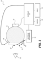
- FIG. 2 depicts a schematic illustration of components that may be contained within the device 100 of FIG. 1 as previously shown in US 7,540,613 .
- the light emitter 106 provides a light stimulus to the eye 144.
- Current high brightness LED's have sufficient brightness for carrying out the present invention with an efficient diffuser, however, in certain applications a plurality of LEDs may be used for a light emitter 106.
- a light emitter 106 is controlled by a controller 110 that provides the overall control of the device 100.
- Controller 110 may be a microcontroller or microcomputer device with a processor, memory and other connections to other components of device 100. Controller 110 may be a pre-programmed computer that is programmed to perform the functions and controls described herein. Alternatively, controller 110 may include wireless connections or wired connections that allow remote programming ( e.g ., for additional functions or updates). Those of ordinary skill in the art would understand how to program and operate controller 110.
- Control of the light emitter 106 is by means of the controller 110 which can control the timing of the firing of the light and camera sources, as well as the intensity, frequency and synchronicity thereof as further described below.
- the controller 110 can modulate the activity of the light emitter 106, such as an LED to provide a series of brief flashes of light of predetermined duration, however, other stimulus waveforms or stimulus frequencies can also be utilized as further described below.
- the light emitter 106 is positioned so as to emit light to the interior of a diffuse spheroidal reflector 142 so that the light from the light source is directed uniformly toward the eye 144 from all directions.
- the diffuse spheroidal reflector 142 is spheroidal in configuration with a white interior surface to enhance the reflectivity.
- the white surface can be a coating (e.g., paint) or diffuse spheroidal reflector 142 can be made for example, from white plastic.
- the use of the diffuse spheroidal reflector 142 provides an even illumination to most of the retina of the eye 144.
- Diffuse spheroidal reflector 142 is an exemplary optical assembly 104.
- the light stimulus by the light emitter 106 gives rise to an electrical signal from the eye 144 that can be sensed by e.g ., electrodes 132, 134 contacting the skin of the patient proximate to the eye 144, whereby the electrical signal is communicated by wires 148 to an amplifier and an analog to digital (A/D) converter shown as block 150.
- the A/D converter (located for example on the electronics board 109 in FIG. 1 ) can measure the electric signals on the electrodes and provide the information to the controller 110.
- the controller 110 can analyze the electric signals so as to provide an indication of visual system function, using techniques described for example, in the references cited in the Background section above.
- the analysis of the data from the electrical signals sensed by the electrodes 132, 134 is, as described, carried out by the controller 110.
- Algorithms for specifically assessing retinal ischemia in a patient have been published. See, for example, Sevems et al. (1991), Severns and Joshson (1991), and Kjeka et al. (2013). For other diseases, algorithms are described in the references cited in the Background section above.
- signals from the skin electrodes 132, 134 are analyzed for the amount of noise present to determine if accurate and clinically meaningful measurements can be made. If the signal to noise ratio is marginal, additional data can be collected to improve the estimate. Next, a sine wave is fit to the data to determine the amount of elapsed time between the actuation of the stimulus and the maximal response of the eye. This measurement has been shown to be a highly sensitive measure of the extent of ischemia in the eye (Severns et al. (1991)).
- the device 100 As further components of the device 100, ( FIG. 1 ) there are controls 120 that can be used to initiate each test and to enter customized settings.
- the device 100 can provide a visual readout 118 to the user of the results of each test, that is, the readout 118 provides a visual readout to the user that is related to the amount of retinal ischemia of the eye.
- the amplifier can be a biomedical amplifier using 24 bit (or more) A/D converters that eliminates gain adjustment and the prolonged recovery from saturation of conventional amplifiers.
- conventional amplifiers have required some oversight by a technician during testing to assure that the gain setting was correctly matched to the input range of the A/D converter. Further, such conventional amplifiers could saturate (fail to respond to the input signal) and might take tens of seconds to recover the ability to respond to a signal. The saturation is difficult to distinguish from a lack of response from the patient making reliable automation of signal acquisition difficult.
- the device 100 may utilize a low gain differential amplifier (no more than 32x) and a high resolution (typically 18 bits or greater) differential A/D converter to acquire the signal from the eye 144 by means of the skin electrodes 132, 134.
- the amplifier has a very high tolerance for noise and offsets, while producing highly faithful reproduction of the input waveform.
- the amplifier and A/D converter of block 150 are also immune to prolonged saturation caused by interfering signals.
- the amplifier and A/D converter can be built into the same device (e.g ., an ADS1220, ADS1248, ADS1292, ADS1294, ADS1298, or ADS1299 from Texas Instruments or an AD7195, AD7194, AD7193, AD7799, AD7738 from Analog Devices to name a few).
- Some embodiments do not use an amplifier.
- Input impedance of the system is very high (>10 M ⁇ ) so that the relatively high impedance of the electrodes 132, 134 contacting the skin does not affect the results.
- the output of the A/D converter in block 150 is connected to the controller 110, which analyzes the data.
- all the electrodes used for one eye can be located in a self-adhering electrode array such as those described in US Provisional Patent Application Serial No. 61/696,499, filed September 4, 2012 and PCT Application Serial No. PCT/US13/58007, filed September 4, 2013 .
- three electrodes are used in an array for each eye.
- An A/D converter located for example on electronics board 109 can measure the electric potential difference between a first electrode and a second electrode in the electrode array, and a common-mode attenuation circuit can be electrically connected to a third electrode in the electrode array.
- An advantageous and novel arrangement of these electrodes is where the distance between the first and second electrode is greater than both the distance between the first electrode and third electrode and the distance between the second electrode and third electrode.
- the common-mode attenuation circuit can be considered connected to the middle of the three electrodes.
- the common-mode attenuation circuit can reduce the common-mode voltage difference between signals on the electrodes and the A/D converter caused, for example, by capacitive coupling between the power lines and the body. By reducing common-mode interference, potential measurements between electrodes can be made more accurately.
- Exemplary common-mode attenuation circuits include a right leg drive circuit and a constant potential with respect to a potential at the A/D converter.
- An electronics board 109 may have a controller 110 modulating a light emission from the first light emitter to create a first flash of light having a duration less than 21 ms.
- the controller 110 may also modulate a light emission from the second light emitter to create a second flash of light having a duration less than 21 ms.
- the controller 110 may also modulate a light emission from the third light emitter to create a third flash of light having a duration less than 21 ms.
- the controller 110 modulates a light emission from one or more light emitters to create flashes of light having durations less than 21 ms, for example, less than 10 ms, 6 ms, 5 ms, 4 ms, or 3 ms.
- the first light emitter emits green and the second emitter emits blue, then to emit the color cyan, both emitters are needed.
- a common way is to control the flash duration for each source independently.
- the green flash duration may be 2 ms and the blue flash duration 5 ms.
- the starting times for the two flashes may be aligned, or the ending times may be aligned, or to reduce the peak electrical power requirements, the second flash may begin soon after the first completes. Because the flashes are short, even though the durations differ, they are perceived by the brain as a cyan color.
- the retina responds to the light as it arrives, leading to millisecond-level uncertainties in when should the flash be considered to have occurred (in the present example).
- Analogous statements can be made if white light is synthesized from red, green, and blue LEDs.
- Two methods of creating a white flash are by using a white light source (e.g ., a white LED or xenon bulb) or by synthesizing the color using, for example, red, green, and blue LEDs.
- the optical assembly 104 may reflect some wavelengths better than others, leading to deviations from the spectrum of a white light source.
- the color of the optical assembly 104 may also change from part-to-part due to manufacturing variation, leading to part-to-part deviations in the spectrum emitted if a white light source is used.
- the color can be tuned to the desired color, independent of the exact color absorption of the optical assembly 104, when using red, green, and blue LEDs.
- One method to reduce the timing uncertainty caused by flash characteristics is to have the light waveforms overlap in time.
- the independent visible light spectral sources overlap by at least 50%, 60%, 70%, 80%, 90%, 95%, or 99% of the longer of the flashes (whether it be 2, 3, 4, or more independent visible light spectral sources).
- FIG. 4 shows an overlap of 100%, where all the lights flash simultaneously.
- Some embodiments use light flashes that are symmetric about a center point. For example, a 2 ms blue flash can be combined with a 4 ms green flash by having the blue occur in the interval (t-1 ms, t+1 ms) and the green flash over the interval (t-2 ms, t+2 ms).
- the center of each flash occurs at the same time (t ms in this example).
- One method to achieve the desired color without affecting the percentage overlap is to individually adjust the current applied to each source. Brightness can be adjusted either by further current adjustments or the duration of the flash can be changed.
- An infrared light emitter 103 may be optionally used to image the eye in the infrared spectrum. Contrast between the pupil and the iris may be improved with infrared illumination.
- the controller 110 modulates a light emission from an infrared light emitter 103 to create an infrared flash of light having a duration less than 40 ms, 30 ms, 20 ms, 10 ms, 5 ms, or 3 ms.
- the exact duration of the infrared flash may be constant, or may dynamically change in operation to provide varying exposures in camera 101.
- a typical exposure time in some embodiments can be 2.6 ms. However, the exposure time may be varied by the controller 110, for example, based on feedback from sensors.
- a shorter exposure time can be better because images have less motion blur and are less affected by external light, but shorter exposure times also increase the peak electrical power demands of the device 100 and provide less light to the camera 101.
- peak power required by the device 100 is reduced by having light emitted from the light emitter 106 and infrared light emitter 103 occur at substantially different times. Additional advantages exist when the camera 101 acquires images during IR flashes. If the visible light during an IR flash is small, then chromatic aberrations in the images taken by the camera 101 are also small as the spectral content of the illumination is more limited.
- the camera 101 can acquire images primarily in the infrared, which may improve contrast between the pupil and the iris, even if the camera 101 is sensitive to visible and IR light. It may be advantageous to have the camera 101 sensitive to both visible and infrared light in order to reduce cost and/or so that the camera 101 can provide visible-light features to the device 101, such as reading information off of computer displays, smartphones, and the like.
- Some embodiments with the optional infrared light emitter 103 do not have a camera 101; these embodiments may use the infrared light, for example, to trigger other devices by providing synchronization information.
- the energy emitted by the first light emitter during the infrared flash of light can be less than 50%, 40%, 30%, 25%, 20%, 10%, 5%, or 1% of the energy emitted by infrared light emitter during the infrared flash of light.
- the energy emitted by the second light emitter during the infrared flash of light may be less than 50%, 40%, 30%, 25%, 20%, 10%, 5%, or 1% of the energy emitted by the infrared light emitter during the infrared flash of light.
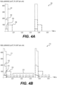
- the first light emitter emits 0% of the energy emitted by the infrared light emitter during the infrared flash of light to minimize chromatic aberrations and to provide better contrast in the IR, as shown in FIG. 4A .
- background illumination e.g ., as shown in FIG. 4B
- some visible light during the infrared may be difficult to avoid and the percentage will be higher than 0%.
- the energy emitted by the third light emitter during the infrared flash of light may be less than 50%, 40%, 30%, 25%, 20%, 10%, 5%, or 1% of the energy emitted by infrared light emitter during the infrared flash of light.
- the controller 110 can modulate a light emission from the first light emitter to create a light stimulus having a stimulus frequency greater than 7 Hz, including but not limited to the list of frequencies near 30 Hz enumerated below.
- the controller 110 may also modulate a light emission from the infrared light emitter 103 to create infrared flashes of light having durations less than 40 ms and an infrared flash frequency greater than 1 Hz.
- controlling the timing between the stimulus frequency and the infrared flash frequency can be advantageous so that, for example, the lighting created by the light stimulus interacts in a consistent manner with the infrared flashes.
- Other potential advantages of controlling the timing between the two frequencies include reduced peak power, better contrast with less chromatic aberration and less changes to lighting levels in embodiments using a camera sensitive to visible and IR light. Without time synchronization, lighting levels in embodiments using a camera sensitive to visible and IR light will vary at the beat frequency between the visible and infrared light frequencies.
- the energy emitted by the first light emitter during the infrared flashes of light is less than 50% of the energy emitted by infrared light emitter during the infrared flash of light, and the ratio of the stimulus frequency to the infrared flash frequency is within 1% of an integer or within 1% of the reciprocal of an integer, for example, the ratio can be 1.
- the light emitter 106 generates visible light that can stimulate the visual system of a patient.
- the light emitter 106 creates a light stimulus that occurs on a periodic basis having a stimulus frequency within 0.01 Hz of one of the following frequencies: 26.94, 27.13, 27.32, 27.51, 27.70, 27.90, 28.10, 28.31, 28.51, 28.72, 28.94, 29.15, 29.37, 29.59, 29.82, 30.05, 30.28, 30.52, 30.76, 31.00, 31.25, 31.50, 31.76, 32.02, 32.28, 32.55, 32.83, 33.10, 33.67 Hz, or integer multiples thereof. Other frequencies may be used.
- the light emitter 106 creates a light stimulus having a stimulus frequency within 0.1 Hz of 28.31, 28.72, or 32.55 Hz, or integer multiples thereof.
- the light emitter 106 can creates flashes at a sufficiently large frequency (e.g ., above about 50 Hz) so that the light appears to be constantly on.
- the frequency is lower than 40 Hz and may appear to flash or flicker.
- the light emitter 106 creates flashes at a frequency above about 50 Hz and additional light at a frequency lower than 40 Hz, creating the appearance of a flickering light on top of a constant background.
- the device 100 can create a flickering light at a frequency within 0.01 Hz of 28.31 Hz and a perceptually-constant background at a frequency within 0.1 Hz of 283.06 Hz.
- the light emitter 106 generates a light stimulus having a stimulus frequency greater than 7 Hz.
- FIG. 4 shows exemplary timing diagrams for light waveforms described above.
- Plot 300 shows 1.5 periods of synthesized white light flash followed by an IR flash. Both the synthesized white light flash (also referred to as the stimulus) and IR flash occur at a stimulus frequency of about 28.306 Hz. Consequently, the ratio of the visible light flash frequency and the infrared light flash frequency is 1.
- Curve 301 depicts the luminance output of a green LED that is part of the light emitter 106, as measured at the eyecup 107.
- Curves 302, 303 depict the corresponding luminance outputs from red and blue (respectively) LEDs that are also part of the light emitter 106 measured at the eyecup 107.
- Curve 304 depicts output from the infrared light emitter 103. In this example, there is no overlap between the output of visible light and infrared light.
- Plot 310 is analogous to plot 300, with the exception the addition of a background illumination.
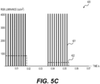
- the background illumination is created in this example with 283.06 Hz flashes of the red, green, and blue LEDs, 7 of which are indicated by designator 315.
- the 283.06 Hz background frequency is higher than the patient's critical fusion frequency and thus is perceived to be a constant illumination. While in this example, the background frequency is 10 times the stimulus frequency, other multiples are contemplated as well (including multiples of 2, 3, 4, 5, 6, 7, 8, 9, 11, 12, 13, 14, 15, 16, 17, 18, 19, 20, or more).
- the red, green, blue, and infrared waveforms are indicated with the same dashing patterns as in plot 300, and with the designators 312, 311, 313, and 314 respectively.
- 2 of the background flashes occur during the infrared light emission and 1 of the background flashes occurs during the stimulus flash.
- the same or different light emitters can be used to create the background and stimulus illumination.
- a camera 101 may be optionally used to image the eye of the patient periodically at a frame rate frequency.
- a controller 110 in the device 100 can use the images, for example, to detect the eye's pupil and measure its area. If the pupil cannot be detected, the device 100 may be configured to not present results as a safeguard to reduce the likelihood of presenting erroneous results. Alternatively, the device 100 may present results irrespective of a pupil being detected, which may be advantageous in cases such as stimulating the eye through a closed eyelid.
- the controller 110 may modulate a light emission from the first light emitter creating a light stimulus having a stimulus frequency greater than 7 Hz, including but not limited to the list of frequencies near 30 Hz enumerated earlier in this disclosure.
- controlling the timing between the stimulus frequency and the frame rate can be advantageous so that, for example, (a) the lighting created by the light stimulus interacts in a consistent manner with the image acquisition by the camera 101, and/or (b) updates to stimulus luminance based on pupil area measurements happen in a consistent manner.
- the ratio of the stimulus frequency to the frame rate is within 1% of an integer or within 1% of the reciprocal of an integer, for example, the ratio can be 1. In some embodiments, the ratio of the stimulus frequency to the frame rate is greater than 7, for example, 8, 9, 10, 11, 12, 13, 14, 15, or more. High ratios can occur (but are not required to occur), for example, when using pulse-width modulation to create light stimuli that approximate a retinal irradiance that varying as a sinusoid, a square wave having a duty cycle between 30% and 70%, or a triangular wave.
- the frame rate may equal the flash rate from the infrared light emitter 103 (i.e ., 1 IR flash per image) and the ratio of these rates to the stimulus frequency can be 1% of an integer or within 1% of the reciprocal of an integer (for example, 1).
- a controller 110 in the device 100 can measure the area of the patient's pupil. With this information, the controller 110 can adjust light stimulus as a function of the area. This adjustment may be useful, for example, to reduce the intra-patient and/or inter-patient variability that results from differences in retinal illumination caused by variations in pupil area.
- the adjustment of the light stimulus as a function of pupil area can occur at the frame rate frequency and/or other frequencies such as a frequency faster than 0.5 Hz, 1 Hz, 2 Hz, 5 Hz, 10 Hz or 20 Hz.
- the adjustment of the light stimulus as a function of the pupil area does not have to happen on a periodic basis; for example, a microprocessor on the controller may have a peak CPU load greater than 100% which causes an adjustment to be occasionally missed.
- a microprocessor on the controller may have a peak CPU load greater than 100% which causes an adjustment to be occasionally missed.
- the timing of the response to a 30 Hz flicker stimulus depends on the intensity of the light.
- the eyes were dilated and an artificial pupil having a diameter of 5 mm was inserted so as to make the stimulus pupil size independent.
- FIG. 3 Exemplary relations between luminance of the visual stimulus and the pupil area are shown in FIG. 3 , where FIG. 3A shows the relation between the light emitted from the device 100 and pupil area; FIG. 3B shows the relation between retinal illuminance and pupil area.
- Curve 201 shows a flash luminance that is independent of pupil area.
- the total amount of light entering the eye changes linearly with pupil area.
- the light stimulus can be linearly related to the multiplicative inverse of the eye's pupil area.
- the light stimulus can be made so that the energy entering the eye is constant, independent of pupil size.
- Curves 203 and 213 show this relation, where the amount of light entering the eye is constant.
- the light stimulus can be related to the multiplicative inverse of the eye's pupil area through a non-linear, concave function.
- a non-linear concave function can compensate for the eye's reduced sensitivity to light entering away from the center of the pupil (e.g., the Stiles-Crawford effect).
- the amount the light is reduced as the area increases is smaller than the amount that the pupil area increased.
- Curves 202 and 212 show this relation, where the amount of light entering the eye increases slowly with pupil area, as the effectiveness of stimulating the retina is reduced for light not entering the center of the pupil.
- the device 100 may measure the area of the patient's pupil. In cases where the area of the pupil cannot be measured (for example, because the eyelids are closed), the controller 110 may estimate the pupil size based on previous measurements. If the pupil has not yet been identified, the controller may indicate so to the device operator and not provide a result ( i.e., an indication of visual system function). The controller 110 may be arranged so as to wait indefinitely or for a predetermined amount of time before the initial pupil acquisition before proceeding with the remainder of the test process. This fail-safe procedure helps prevent erroneous results.
- the controller 110 may also indicate an error to the device operator and not provide a result.
- the device 100 has a light detector 105 that can monitor the output of the light emitter 106.
- the light detector 105 can comprise, for example, a photodiode.
- the light detector 105 can also monitor the amount of light originating outside the device 100 that enters the optical assembly 104 (herein called "external light").
- the light detector 105 can generate an expected set of signals, based for example on expected levels of external light and/or expected levels of the light emitter 106. If these expectations are not met, the controller 110 may not provide a result.
- the threshold can be between 1 cd/m 2 and 200 cd/m 2 .
- the threshold can be between 3 cd/m 2 and 30 cd/m 2 .
- the threshold can be between 10 cd/m 2 and 100 cd/m 2 .
- the amount of external light may be combined with information regarding the pupil size of the eye being tested to determine if the amount of external light is too large.
- the threshold can be a value between 10 Td and 1000 Td.
- the threshold can be a value between 30 Td and 300 Td.
- the threshold can also depend on the stimulus. For example, dimmer stimuli may require a lower threshold.
- the amount of external light can be used to modify the stimulus in order to reduce the effect of external light on the electrical measurement.
- the optional light detector 105 may be used to monitor the light stimulus so that the controller 110 can compensate for variations in the output of the light emitter 106 or the optical efficiency of the optical assembly 104.
- the controller 110 can adjust, for example during a calibration phase of a test, the output of light emitter 106 in order to achieve a desired signal from light detector 105. If the adjustment is too great, the device 100 may be configured to report an error rather than possibly providing erroneous results.
- the device 100 has an electrical impedance meter measuring the impedance associated with the electrical signal received from the visual system of the patient attached through the patient connector 108. If the impedance is too large, the device 100 may not be electrically connected to the patient or the connection may be of such a poor quality as to comprise the signal quality. In some embodiments, the controller 110 does not provide an indication of visual system function unless the impedance is less than a target value, such as 1 G ⁇ , 500 M ⁇ , 150 M ⁇ , 15 M ⁇ , 1.5 M ⁇ , 150 k ⁇ , 100 k ⁇ , 50 k ⁇ , 25 k ⁇ , 10 k ⁇ , or 5 k ⁇ .
- a target value such as 1 G ⁇ , 500 M ⁇ , 150 M ⁇ , 15 M ⁇ , 1.5 M ⁇ , 150 k ⁇ , 100 k ⁇ , 50 k ⁇ , 25 k ⁇ , 10 k ⁇ , or 5 k ⁇ .
- the high end of these values e.g ., 1 G ⁇ , 500 M ⁇ , 150 M ⁇ , or similar
- the embodiments may indicate that an effective connection with little noise has been made.
- achieving the lower end of impedance may not be reasonably practicable or worthwhile because of the skin preparations required to get that low of an impedance.
- the impedance near the high end 150 M ⁇ is sufficient.
- Other embodiments may require a lower impedance.
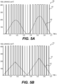
- FIG. 5 three exemplary timing diagrams for light waveforms are shown.
- Plot 400 shows 2 periods of synthesized white light, occurring at a stimulus frequency of about 28.306 Hz.
- Curve 402 represents the desired sinusoidal stimulus while pulse train 401 represents a pulse-width modulation (PWM) approximation to curve 402.
- PWM pulse-width modulation
- the PWM period is 10 times the stimulus period; however, other ratios of stimulus period to PWM period are contemplated, including ratios greater than or equal to 7. In some embodiments, integer ratios are preferred because each period is thereby more similar to each other.
- Curve 402 shows 2 periods, however, the amplitude of the 2 periods are not the same.
- a controller 110 can measure the area of the patient's pupil. With this information, the controller 110 can adjust the luminance as a function of the area. Between the first and second period of curve 402, the device 100 measured the pupil to be smaller and therefore increased the brightness of the desired light waveform in order to reduce the effect of pupil size on retinal stimulation.
- Plot 410 is analogous to Plot 400, except the desired light waveform is a triangular wave.
- Curve 412 is the desired triangular wave and pulse train 411 is the PWM approximation thereof.
- Plot 420 is also analogous to Plot 400, except a square wave is the desired light waveform.
- Curve 422 is a 50% duty cycle square wave.
- Other duty cycles are also contemplated, for example square waves having a duty cycle between 30% and 70%, and square waves having a duty cycle between 40% and 60%. Short duty cycles (e.g., ⁇ 20%) may be implemented with a single flash such as shown in FIG. 4 .
- Pulse train 421 is a PWM approximation to Curve 422.
- the stimulus period is 20 times the PWM period.
- Curve 422 has the second period being smaller in amplitude than the first, which may occur, for example, when the device 100 measures an increase in pupil area.
- the device 100 directly synthesizes a continuous light waveform that approximates a retinal irradiance that varies as one of a sinusoid, a square wave having a duty cycle between 30% and 70%, or a triangular wave.
- the device 100 uses pulse-width modulation (PWM) to create a light stimulus approximating a retinal irradiance varying as one of a sinusoid, a square wave having a duty cycle between 30% and 70%, or a triangular wave.
- PWM pulse-width modulation
- the controller 110 can use PWM to control the output of a first light emitter and a second light emitter in order to deliver a periodic visual stimulus to the eye approximating a retinal irradiance varying as one of a sinusoid, a square wave having a duty cycle between 30% and 70%, or a triangular wave.
- the controller 110 can use PWM to control the output of a first light emitter and a second light emitter in order to deliver a periodic visual stimulus to the eye approximating a retinal irradiance varying as a sinusoid.
- the controller 110 in the electronics board 109 can be any of those known in the art.
- the controller 110 can be a single microprocessor, for example, one sold by Analog Devices, Atmel, Intel, Microchip, Texas Instruments, etc. Alternatively, the controller 110 can be distributed among many integrated circuits on one or more printed circuit boards in the device 100.
- the controller 110 can be configured to modulate the light output of a first light emitter and to receive and analyze the electrical signal from a patient.
- the controller 110 can communicate with a camera and measure the pupil size in images taken with the camera. In some embodiments, the controller 110 can modulate the light output from additional light emitters, such as a second light emitter, a third light emitter, and/or an infrared light emitter. The controller 110 can provide to the operator an indication for visual system function of a human using a display and/or providing a means to communicate the information to a computer or other electronic device.
- additional light emitters such as a second light emitter, a third light emitter, and/or an infrared light emitter.
- the controller 110 can provide to the operator an indication for visual system function of a human using a display and/or providing a means to communicate the information to a computer or other electronic device.
- compositions methods of their use are also contemplated.
- the methods involve illuminating an eye of the patient with a light stimulus.
- the methods also involve either receiving and analyzing an electrical signal from the patient so as to provide an indication of visual system function or measuring the electric potential difference between a first electrode and second electrode so as to provide an indication of visual system function.
- Illuminating the eye may comprise visible flashes of light having a duration less than 21 ms from 1, 2, 3, or more distinct spectral sources.
- these flashes of light come from a plurality of spectral sources, they can be configured to overlap in time by at least 50%, 60%, 70%, 80%, 90%, 95%, or 99% of the longest of the flashes so as to reduce the timing uncertainty as described earlier in this disclosure.
- the methods may involve measuring the eye's pupil area and adjusting the energy in the first flash (or other light stimuli) as a function of the eye's pupil area, for example, wherein the energy in the first flash is linearly related to the multiplicative inverse of the eye's pupil area or wherein the energy in the first flash is related to the multiplicative inverse of the eye's pupil area through a non-linear, concave function.
- the light stimulus comprises flashes of light having a flash frequency greater than 7 Hz and the measuring of the eye's pupil area occurs at a frame rate wherein the ratio of the flash frequency to the frame rate frequency is within 1% of an integer or within 1% of the reciprocal of an integer - these features may occur separately or together with the overlapping flashes described above.
- the light stimulus comprises flashes of light having a flash frequency greater than 7 Hz and the eye is also illuminated with infrared flashes of light that have most of their energy emitted at wavelengths longer than 710 nm, wherein the infrared flash frequency is greater than 1 Hz , wherein the energy emitted by the first light emitter during the infrared flash of light is less than 50% of the energy emitted by infrared light emitter during the infrared flash of light, and wherein the ratio of the stimulus frequency to the infrared flash frequency is within 1% of an integer or within 1% of the reciprocal of an integer - these features may occur separately or in any combination of frame rate and overlapping flash methods described above.
- Some methods involve placing an electrode array comprising three electrodes on the skin of the patient as a single unit, wherein the three electrodes include a first electrode, a second electrode and a third electrode, wherein the first and second electrode are more distant from each other than any other pairing of the first, second, and third electrodes, which can occur separately or in any combination with infrared flashing, frame rate, and overlapping flash methods described above.
- Some methods involve measuring the eye's pupil area and adjusting the luminance of the light stimulus through a non-linear, concave function of the eye's pupil area, which can occur separately or in any combination with the electrode array, infrared flashing, frame rate, and overlapping flash methods described above. Some methods involve measuring the eye's pupil area and adjusting the luminance of the light stimulus as a function of the eye's pupil area, wherein the light stimulus that approximates a retinal irradiance that varies as one of a sinusoid, a square wave having a duty cycle between 30% and 70%, or a triangular wave, which can occur separately or in any combination with the electrode array, infrared flashing, frame rate, and overlapping flash methods described above.
- Some methods include techniques to reduce erroneous results, each of which can be used separately or in combination with any of the other methods. Some methods include attempting to locate the eye's pupil in images taken by a camera and not returning an indication of visual system function unless the eye's pupil has been identified. Some methods include receiving a signal from the light detector and not returning an indication of visual system function if the signal from the light detector differs from a set of expected light detector signals, wherein the set of expected light detector signals comprises monitoring for external light exceeding a threshold.
- the threshold can be any of those described above, including those dependent and independent of pupil area.
- Some methods include measuring the eye's pupil area and adjusting the luminance of the light as a function of the eye's pupil area, and measuring an electrical impedance associated with the electrical signal received from the patient, wherein the indication is not provided unless the electrical impedance meter measures an impedance smaller than a target value.
- the target value can be any of those described above, including those in the G ⁇ , M ⁇ , and k ⁇ range.
Landscapes
- Health & Medical Sciences (AREA)
- Life Sciences & Earth Sciences (AREA)
- Surgery (AREA)
- Animal Behavior & Ethology (AREA)
- Veterinary Medicine (AREA)
- Engineering & Computer Science (AREA)
- Biomedical Technology (AREA)
- Heart & Thoracic Surgery (AREA)
- Medical Informatics (AREA)
- Molecular Biology (AREA)
- Physics & Mathematics (AREA)
- Biophysics (AREA)
- General Health & Medical Sciences (AREA)
- Public Health (AREA)
- Ophthalmology & Optometry (AREA)
- Pathology (AREA)
- Nuclear Medicine, Radiotherapy & Molecular Imaging (AREA)
- Radiology & Medical Imaging (AREA)
- Eye Examination Apparatus (AREA)
- External Artificial Organs (AREA)
- Control And Other Processes For Unpacking Of Materials (AREA)
- Apparatus Associated With Microorganisms And Enzymes (AREA)
Description
- The embodiments described herein relate to improved devices and methods for assessing visual system function.
- The electroretinogram (ERG) and visual evoked potentials (VEP) are diagnostic tests used to help assess visual system function. See, for example, the textbook Principles and Practice of Clinical Electrophysiology of Vision, 2nd edition, edited by Heckenlively and Arden (2006), which describes dozens of diseases that can be diagnosed with the aid of visual electrophysiology. Standards have been developed for the most common of these tests, as described in Marmor et al. (2009), Hood et al. (2012), Holder et al. (2007), and Odom et al. (2010). As a specific example, some features of the clinical ERG are strongly correlated with diabetic retinopathy (Bresnick and Palta (1987), Han and Ohn (2000) and Satoh et al. (1994)). As another example, Kjeka et al. (2013) showed greatly improved outcomes for the treatment of central retinal vein occlusion when basing treatment decisions on ERG results rather than ophthalmologic examinations alone.
- Normally, ERG measurements are recorded using a large instrument (e.g., the LKC Technologies UTAS system) in a darkened room with electrodes placed directly onto the eye. Dilating drops are used to enlarge the pupil and anesthetic drops are used to numb the eye before placing the electrodes onto the eye. The eye is stimulated with light to elicit a response from the visual system which is recorded via the electrodes. The measurements are performed by a skilled technician, and the results are usually interpreted by an ophthalmologist or PhD expert in visual electrophysiology. The invasiveness and complexity described above have prevented the ERG from having widespread use in assessing diabetic retinopathy and other diseases.
- The invention described in
US patent 7,540,613 helps prevent these disadvantages. Nevertheless, there still exists a need for visual electrophysiology devices that are easier to use and/or have improved performance. -
US 2008/058655 discloses a hand-held monitoring device comprising: - a light source (38, paragraph 29) for providing a light stimulation,
- a microcontroller (40) for controlling the light source to emit a series of flashes (paragraph 31) so that the light stimulus on the retina be constant (paragraph 38),
- a camera (52) for imaging the pupil and measuring the area of the pupil (paragraph 38)
- electrodes (32, 34) for obtaining electrical signals (e.g., electroretinogram) related to the visual function in response to the light stimulation (paragraphs 25, 34).
- Described herein are embodiments of a device and method for providing an indication of visual system function. The improvements disclosed herein can be used separately or in combination, including improvements in stimulus generation, ease of use, and error condition monitoring. Embodiments overcome the problems described above.
- An embodiment of a device to provide an indication of visual system function of a patient is defined in
claim 1. - A method for providing an indication of visual system function of a patient is defined in claim 9.
- The accompanying drawings, which are incorporated in and constitute a part of this specification, illustrate several embodiments and together with the description, serve to explain the novel principles of the embodiments described herein. In the drawings:
-
FIG. 1 is a cross sectional view of an exemplary visual electrophysiology device. -
FIG. 2 is a schematic view illustrating components contained within the visual electrophysiology device ofFIG. 1 -
FIG. 3 shows three exemplary relations between luminance and pupil area, from the perspective of luminance emitted from the visual electrophysiology device (FIG. 3A ) and of retinal illuminance (FIG. 3B ). -
FIG. 4 shows timing diagrams of light output versus time for exemplary embodiments described herein.FIG. 4A shows a periodic synthesized white light stimulus followed by an infrared flash.FIG. 4B shows a periodic synthesized white light stimulus followed by an infrared flash, with a superimposed higher-frequency synthesized white light background. -
FIG. 5 shows timing diagrams of light output versus time for exemplary embodiments described herein.FIG. 5A shows a desired sinusoidal waveform and a pulse-width modulation (PWM) approximation thereof.FIG. 5B shows a desired triangular waveform and a PWM approximation thereof.FIG. 5C shows a square waveform and a PWM approximation thereof. - Disclosed herein are embodiments of improved visual electrophysiology devices and methods of improved visual electrophysiology. These devices and methods can be used to provide an indication of visual system function of a patient. There is an electrical circuit that controls a light stimulus directed toward the eye and measures the electrical signal the eye produces in response to the light. Device operation involves stimulating the eye with light and measuring an electrical response to the stimulus. By way of example, the time span between the flash of light and the time of the peak of the electrical response may be indicative of the degree of retinal ischemia in a patient.
- Embodiments of the present invention may improve the measurements over existing visual electrophysiology device measurements, by making the stimulation more consistent, improving the data collection, and/or checking for error conditions. The stimulus to the eye can comprise flashes of light or other modulated light waveforms. The stimulus to the eye can comprise a single flash of light. The stimulus to the eye can comprise a background illumination that is perceptually constant or only slowly changing.
- Embodiments provide a first light emitter having a first emission spectrum. The first light emitter has a first visible emission spectrum and may emit, for example, green, red, orange, blue, amber, or yellow light. The first light emitter may be a LED. Other (2, 3, 4, 5 or more) visible light emitters are present with distinct spectra. For example, some embodiments may use 4 LEDs that each have red, green, and blue emitters. Some embodiments may have an infrared light emitter that emits at least 50% of its energy at wavelengths longer than 710 nm. Other light emitters may be provided.
- The embodiments use a controller to modulate the emitters' output so that they emit light for periods of time (e.g., less than 6 ms, 21 ms or 40 ms) and so that the light emitted from at least some of the visible light emitters overlaps in time. In some embodiments, the emission duration for each emitter is different (e.g., the second light emitter emits light for a longer period of time than the first light emitter).
- The embodiments use a camera to measure the pupil size so the light stimulus luminance can be adjusted to reduce the effect of pupil size on the effective retinal stimulus; for example, the light stimulus luminance can be linearly related to the multiplicative inverse of the eye's pupil area or the light stimulus luminance can be related to the multiplicative inverse of the eye's pupil area through a non-linear, concave function.
- The light emitters can be arranged to deliver retinal illuminances that are approximately sinusoidal, triangular, or square by for example continuously modulating the light output or by delivering flashes of light in a pulse-width modulation (PWM) fashion. In various embodiments, time or frequency synchronization between the light stimulus, optional infrared light flashes, and camera images may provide more consistent stimulation, image collection, light stimulus luminance adjustment, and the like. By varying the above-described characteristics of the light emitters as described herein, embodiments provide improved results over existing visual electrophysiology devices.
- Embodiments may improve over existing visual electrophysiology devices by using electrode arrays and driving a middle electrode with a common-mode attenuation circuit while measuring electric potential differences between the more distantly separated outer electrodes. This electronic configuration maximizes the magnitude of the electric signals while providing the convenience of an easy to use electrode array.
- Embodiments may improve over existing visual electrophysiology devices by checking for error conditions. Electrical impedance measurements may be used to confirm the device is electrically connected to the patient with a sufficiently low impedance. For example, it could determine if the electrode array does not stick sufficiently well to the patient to achieve an electrical connection. A light detector may be used for example to ensure undesired external light is sufficiently small and/or to ensure the desired light stimulus is in fact produced. Pupil detection may be used to ensure the patient's eye is present and open to ensure the light stimulus produced enters the patient's eye.
- Combinations of the above description are also contemplated. Composition and methods of their use are contemplated. Embodiments improve over existing visual electrophysiology devices in other ways apparent from the detailed description herein.
- In order to more clearly understand the embodiments described herein, certain terms are defined as follows. Other terms are defined in other parts of this disclosure.
- The term "light emitter" refers to anything that emits electromagnetic radiation in the UV, visible, and infrared (IR) range. Exemplary light emitters include LEDs, display devices, and gas-discharge devices such as xenon flash lamps and fluorescent bulbs. In some cases herein, the term "infrared" is abbreviated as "IR".
- The term "LED" refers to a light emitting diode. LED includes those comprising semiconductor, organic, and quantum-dots. The term LED includes those with integrated phosphors.
- The term "patient" refers a human or other mammal from which physiological electrical signals are to be measured. It is contemplated that the device will be placed in proximity to the patient to enable stimulation of the patient's visual system and measurement of physiological response thereto.
- The term "retinal illuminance" refers to the product of luminance and pupil area. The unit Troland (abbreviated Td) is a measure of retinal illuminance where luminance has units of cd/m2 and pupil area has units of mm2.
- The phrase "indication of visual system function" refers to the analysis of an electrical signal from the visual system of a patient in response to light. It is to be distinguished from other measures of the visual system based solely on e.g., imaging of the eye structure with fundus photography, OCT, or the like, or psychophysical measures such as visual acuity using a Snellen chart.
- Various embodiments, as well as additional objects, features, and advantages thereof, will be understood more fully from the following description.
-
FIG. 1 shows anexemplary device 100 used to provide an indication of visual system function of a patient. Aneyecup 107 may contact the bony regions around the eye to keep the device against or near the patient. Thelight emitter 106 shines light into anoptical assembly 104, which directs the light to the patient's eye. In this example, theoptical assembly 104 acts as an integrating sphere to deliver the light emitted from thelight emitter 106 in a diffuse manner to the patient's eye. A diffuse light source enables interrogation of large portion of the retina and makes patient fixation less important. Other exemplary optical assemblies do not require light from thelight emitter 106 to be reflected before reaching the patient's eye, for example, the light may be refracted, diffused, scattered, or may have a direct path between the light emitter and the patient's eye. - The
light emitter 106 can have , 2, 3, 4, or more emission sources. For example, thelight emitter 106 can be a first light emitter, which may be a LED or different type of light emitter. The first light emitter has a first emission spectrum. In some embodiments, the first light emitter may emit green, red, orange, blue, amber, or yellow light. The first light emitter may be, for example, a green LED. Thelight emitter 106 can also be a second light emitter. The second light emitter has a visible second emission spectrum that is distinct from the first emission spectrum. The second light emitter may emit green, red, orange, blue, amber, or yellow light as long as the emission spectrum is distinct from the first emission spectrum. The second light emitter may be an LED or a different type of light emitter and may be, for example, a red LED. Thelight emitter 106 can also be a third light emitter. The optional third light emitter has a visible third emission spectrum that, for example, is distinct from the first and second emission spectra. The third light emitter, if present, may emit green, red, orange, blue, amber, or yellow light as long as the emission spectrum is distinct from the first and second emission spectra. The optional third light emitter may be an LED or a different type of light emitter, and may be, for example, a blue LED. Thedevice 100 may have additional (e.g., 4, 5, 6, 7, 8, or more) visible light emitters having distinct spectra; for example, having 4 different visible spectral sources enables independent stimulation of one of the three types of cones or rods in a human (Shapiro et al. (1996)). - The
light emitter 106 can be, for example, an RGB LED, for example, a CREE CLV6Aa, an Avago ASMT-MT000-0001, or an Osram LRTD-C9TP. Thelight emitter 106 can be, for example, a red, green, blue, white LED such as CREE XLamp XM-L. Individual LEDs or other light sources may be used. Two components in thelight emitter 106 are visible in the cross section of thedevice 100; two more are on the other half, for a total of four. The number of components in thelight emitter 106 need not be 4; 1, 2, 3, 4, 5, 6, 7, 8, 9, 10, 11, 12 or more is contemplated. A larger number of components comprising thelight emitter 106 gives improved light uniformity in the integrating sphere and a brighter possible light output; however, larger numbers are inconvenient is terms of manufacturing difficulty and cost. - As shown in
FIG. 1 , acamera 101 can image the patient's eye through the hole in theoptical assembly 104 and theeyecup 107. Theeyecup 107 can be designed to rest on regions around a patient's eye so as to reduce the amount of light originating outside of thedevice 100 from reaching the eye. Alternatively, theeyecup 107 can be designed not to contact the patient. Anoptional fixation light 102 can provide a target for the patient to fixate on during the testing process. When using aninfrared light emitter 103, at least 50% of its energy will be emitted at wavelengths longer than 710 nm. Theinfrared light emitter 103 can be used to illuminate the patient's eye during the exposure time of thecamera 101. In some embodiments, thedevice 100 has neither acamera 101, nor aninfrared light emitter 103. -
Patient connector 108 can be used to make a set of electrical connections to the patient so as to be able to receive an electrical signal from the patient. The electrical signals can be gathered from the patient using any number of electrodes (e.g., 1, 2, 3, 4, 5, 6, 7, 8, 9, 10, or more) operationally connected to thedevice 100 via a cable. Exemplary locations to measure the response include on the surface of the eye (e.g., with electrodes such as Burian Allen electrodes, DTL electrodes, and ERG Jet electrodes), under the epithelium (e.g., with a needle electrode), on the skin near the eye (e.g., with LKC Sensor Strip electrodes as described inUS Patent application 61/696,499 -
FIG. 2 depicts a schematic illustration of components that may be contained within thedevice 100 ofFIG. 1 as previously shown inUS 7,540,613 . InFIG. 2 , thelight emitter 106 provides a light stimulus to theeye 144. Current high brightness LED's have sufficient brightness for carrying out the present invention with an efficient diffuser, however, in certain applications a plurality of LEDs may be used for alight emitter 106. - A
light emitter 106 is controlled by acontroller 110 that provides the overall control of thedevice 100.Controller 110 may be a microcontroller or microcomputer device with a processor, memory and other connections to other components ofdevice 100.Controller 110 may be a pre-programmed computer that is programmed to perform the functions and controls described herein. Alternatively,controller 110 may include wireless connections or wired connections that allow remote programming (e.g., for additional functions or updates). Those of ordinary skill in the art would understand how to program and operatecontroller 110. Control of thelight emitter 106 is by means of thecontroller 110 which can control the timing of the firing of the light and camera sources, as well as the intensity, frequency and synchronicity thereof as further described below. By way of example, thecontroller 110 can modulate the activity of thelight emitter 106, such as an LED to provide a series of brief flashes of light of predetermined duration, however, other stimulus waveforms or stimulus frequencies can also be utilized as further described below. - The
light emitter 106 is positioned so as to emit light to the interior of a diffusespheroidal reflector 142 so that the light from the light source is directed uniformly toward theeye 144 from all directions. In the illustrated embodiment, the diffusespheroidal reflector 142 is spheroidal in configuration with a white interior surface to enhance the reflectivity. The white surface can be a coating (e.g., paint) or diffusespheroidal reflector 142 can be made for example, from white plastic. The use of the diffusespheroidal reflector 142 provides an even illumination to most of the retina of theeye 144. Diffusespheroidal reflector 142 is an exemplaryoptical assembly 104. - Returning to
FIG. 2 , as previously explained, the light stimulus by thelight emitter 106 gives rise to an electrical signal from theeye 144 that can be sensed by e.g.,electrodes eye 144, whereby the electrical signal is communicated bywires 148 to an amplifier and an analog to digital (A/D) converter shown asblock 150. The A/D converter (located for example on theelectronics board 109 inFIG. 1 ) can measure the electric signals on the electrodes and provide the information to thecontroller 110. Thecontroller 110 can analyze the electric signals so as to provide an indication of visual system function, using techniques described for example, in the references cited in the Background section above. - The analysis of the data from the electrical signals sensed by the
electrodes controller 110. Algorithms for specifically assessing retinal ischemia in a patient have been published. See, for example, Sevems et al. (1991), Severns and Joshson (1991), and Kjeka et al. (2013). For other diseases, algorithms are described in the references cited in the Background section above. - In exemplary embodiments, signals from the
skin electrodes - As further components of the
device 100, (FIG. 1 ) there arecontrols 120 that can be used to initiate each test and to enter customized settings. In addition, thedevice 100 can provide avisual readout 118 to the user of the results of each test, that is, thereadout 118 provides a visual readout to the user that is related to the amount of retinal ischemia of the eye. - The amplifier can be a biomedical amplifier using 24 bit (or more) A/D converters that eliminates gain adjustment and the prolonged recovery from saturation of conventional amplifiers. Typically, conventional amplifiers have required some oversight by a technician during testing to assure that the gain setting was correctly matched to the input range of the A/D converter. Further, such conventional amplifiers could saturate (fail to respond to the input signal) and might take tens of seconds to recover the ability to respond to a signal. The saturation is difficult to distinguish from a lack of response from the patient making reliable automation of signal acquisition difficult.
- To avoid such problems, the
device 100 may utilize a low gain differential amplifier (no more than 32x) and a high resolution (typically 18 bits or greater) differential A/D converter to acquire the signal from theeye 144 by means of theskin electrodes block 150 are also immune to prolonged saturation caused by interfering signals. In some embodiments, the amplifier and A/D converter can be built into the same device (e.g., an ADS1220, ADS1248, ADS1292, ADS1294, ADS1298, or ADS1299 from Texas Instruments or an AD7195, AD7194, AD7193, AD7799, AD7738 from Analog Devices to name a few). Some embodiments do not use an amplifier. Input impedance of the system is very high (>10 MΩ) so that the relatively high impedance of theelectrodes block 150 is connected to thecontroller 110, which analyzes the data. - Conveniently, all the electrodes used for one eye can be located in a self-adhering electrode array such as those described in
US Provisional Patent Application Serial No. 61/696,499, filed September 4, 2012 PCT Application Serial No. PCT/US13/58007, filed September 4, 2013 . In some embodiments, three electrodes are used in an array for each eye. An A/D converter (located for example on electronics board 109) can measure the electric potential difference between a first electrode and a second electrode in the electrode array, and a common-mode attenuation circuit can be electrically connected to a third electrode in the electrode array. An advantageous and novel arrangement of these electrodes is where the distance between the first and second electrode is greater than both the distance between the first electrode and third electrode and the distance between the second electrode and third electrode. As a result, the common-mode attenuation circuit can be considered connected to the middle of the three electrodes. - In contrast, current practice (as described in the ISCEV standard Marmor et al. (2009)) uses remote locations such as the earlobe for a common-mode attenuation circuit electrode location. When electrodes are located on a small sensor array, however, the performance is improved by maximizing the distance between the first and second electrode. For example, in one embodiment, the first electrode can be located under the eye, the second electrode can be located near the temple, and the third electrode can be located in between the first electrode and the second electrode. The common-mode attenuation circuit can reduce the common-mode voltage difference between signals on the electrodes and the A/D converter caused, for example, by capacitive coupling between the power lines and the body. By reducing common-mode interference, potential measurements between electrodes can be made more accurately. Exemplary common-mode attenuation circuits include a right leg drive circuit and a constant potential with respect to a potential at the A/D converter.
- An
electronics board 109 may have acontroller 110 modulating a light emission from the first light emitter to create a first flash of light having a duration less than 21 ms. Thecontroller 110 may also modulate a light emission from the second light emitter to create a second flash of light having a duration less than 21 ms. Thecontroller 110 may also modulate a light emission from the third light emitter to create a third flash of light having a duration less than 21 ms. Generally, thecontroller 110 modulates a light emission from one or more light emitters to create flashes of light having durations less than 21 ms, for example, less than 10 ms, 6 ms, 5 ms, 4 ms, or 3 ms. - When constructing flashes of light from multiple different colored sources, there are several alternative ways to do so. For example, if the first light emitter emits green and the second emitter emits blue, then to emit the color cyan, both emitters are needed. A common way is to control the flash duration for each source independently. For example, the green flash duration may be 2 ms and the blue flash duration 5 ms. The starting times for the two flashes may be aligned, or the ending times may be aligned, or to reduce the peak electrical power requirements, the second flash may begin soon after the first completes. Because the flashes are short, even though the durations differ, they are perceived by the brain as a cyan color. However, the retina responds to the light as it arrives, leading to millisecond-level uncertainties in when should the flash be considered to have occurred (in the present example). Analogous statements can be made if white light is synthesized from red, green, and blue LEDs. One common visual electrophysiology test, the 30 Hz flicker electroretinogram (Marmor et al. (2009)), has response times in the range of 20-40 ms, where a few milliseconds of uncertainty caused by the flash characteristics may produce errors in the measurements.
- Nevertheless, appropriately synthesized colors have advantages over single LEDs. Two methods of creating a white flash, for example, are by using a white light source (e.g., a white LED or xenon bulb) or by synthesizing the color using, for example, red, green, and blue LEDs. The
optical assembly 104 may reflect some wavelengths better than others, leading to deviations from the spectrum of a white light source. The color of theoptical assembly 104 may also change from part-to-part due to manufacturing variation, leading to part-to-part deviations in the spectrum emitted if a white light source is used. In contrast, the color can be tuned to the desired color, independent of the exact color absorption of theoptical assembly 104, when using red, green, and blue LEDs. - One method to reduce the timing uncertainty caused by flash characteristics is to have the light waveforms overlap in time. In some embodiments, the independent visible light spectral sources overlap by at least 50%, 60%, 70%, 80%, 90%, 95%, or 99% of the longer of the flashes (whether it be 2, 3, 4, or more independent visible light spectral sources).
FIG. 4 shows an overlap of 100%, where all the lights flash simultaneously. Some embodiments use light flashes that are symmetric about a center point. For example, a 2 ms blue flash can be combined with a 4 ms green flash by having the blue occur in the interval (t-1 ms, t+1 ms) and the green flash over the interval (t-2 ms, t+2 ms). Thus, the center of each flash occurs at the same time (t ms in this example). One method to achieve the desired color without affecting the percentage overlap is to individually adjust the current applied to each source. Brightness can be adjusted either by further current adjustments or the duration of the flash can be changed. - An
infrared light emitter 103 may be optionally used to image the eye in the infrared spectrum. Contrast between the pupil and the iris may be improved with infrared illumination. Thecontroller 110 modulates a light emission from aninfrared light emitter 103 to create an infrared flash of light having a duration less than 40 ms, 30 ms, 20 ms, 10 ms, 5 ms, or 3 ms. The exact duration of the infrared flash may be constant, or may dynamically change in operation to provide varying exposures incamera 101. A typical exposure time in some embodiments can be 2.6 ms. However, the exposure time may be varied by thecontroller 110, for example, based on feedback from sensors. - Generally, a shorter exposure time can be better because images have less motion blur and are less affected by external light, but shorter exposure times also increase the peak electrical power demands of the
device 100 and provide less light to thecamera 101. - In some embodiments, it is advantageous to minimize the energy emitted by the visible light stimulus to the retina when the infrared light is flashed on and off. First, peak power required by the
device 100 is reduced by having light emitted from thelight emitter 106 andinfrared light emitter 103 occur at substantially different times. Additional advantages exist when thecamera 101 acquires images during IR flashes. If the visible light during an IR flash is small, then chromatic aberrations in the images taken by thecamera 101 are also small as the spectral content of the illumination is more limited. Moreover, if the visible light during an IR flash is small, thecamera 101 can acquire images primarily in the infrared, which may improve contrast between the pupil and the iris, even if thecamera 101 is sensitive to visible and IR light. It may be advantageous to have thecamera 101 sensitive to both visible and infrared light in order to reduce cost and/or so that thecamera 101 can provide visible-light features to thedevice 101, such as reading information off of computer displays, smartphones, and the like. - Some embodiments with the optional infrared
light emitter 103 do not have acamera 101; these embodiments may use the infrared light, for example, to trigger other devices by providing synchronization information. - The energy emitted by the first light emitter during the infrared flash of light can be less than 50%, 40%, 30%, 25%, 20%, 10%, 5%, or 1% of the energy emitted by infrared light emitter during the infrared flash of light. Similarly, in embodiments having a second light emitter, the energy emitted by the second light emitter during the infrared flash of light may be less than 50%, 40%, 30%, 25%, 20%, 10%, 5%, or 1% of the energy emitted by the infrared light emitter during the infrared flash of light.
- In some embodiments, the first light emitter emits 0% of the energy emitted by the infrared light emitter during the infrared flash of light to minimize chromatic aberrations and to provide better contrast in the IR, as shown in
FIG. 4A . If background illumination is used (e.g., as shown inFIG. 4B ), then some visible light during the infrared may be difficult to avoid and the percentage will be higher than 0%. Similarly, in embodiments having a third light emitter, the energy emitted by the third light emitter during the infrared flash of light may be less than 50%, 40%, 30%, 25%, 20%, 10%, 5%, or 1% of the energy emitted by infrared light emitter during the infrared flash of light. - The
controller 110 can modulate a light emission from the first light emitter to create a light stimulus having a stimulus frequency greater than 7 Hz, including but not limited to the list of frequencies near 30 Hz enumerated below. Thecontroller 110 may also modulate a light emission from theinfrared light emitter 103 to create infrared flashes of light having durations less than 40 ms and an infrared flash frequency greater than 1 Hz. - In some cases, controlling the timing between the stimulus frequency and the infrared flash frequency can be advantageous so that, for example, the lighting created by the light stimulus interacts in a consistent manner with the infrared flashes. Other potential advantages of controlling the timing between the two frequencies include reduced peak power, better contrast with less chromatic aberration and less changes to lighting levels in embodiments using a camera sensitive to visible and IR light. Without time synchronization, lighting levels in embodiments using a camera sensitive to visible and IR light will vary at the beat frequency between the visible and infrared light frequencies.
- In some embodiments, the energy emitted by the first light emitter during the infrared flashes of light is less than 50% of the energy emitted by infrared light emitter during the infrared flash of light, and the ratio of the stimulus frequency to the infrared flash frequency is within 1% of an integer or within 1% of the reciprocal of an integer, for example, the ratio can be 1.
- The
light emitter 106 generates visible light that can stimulate the visual system of a patient. In some embodiments, thelight emitter 106 creates a light stimulus that occurs on a periodic basis having a stimulus frequency within 0.01 Hz of one of the following frequencies: 26.94, 27.13, 27.32, 27.51, 27.70, 27.90, 28.10, 28.31, 28.51, 28.72, 28.94, 29.15, 29.37, 29.59, 29.82, 30.05, 30.28, 30.52, 30.76, 31.00, 31.25, 31.50, 31.76, 32.02, 32.28, 32.55, 32.83, 33.10, 33.67 Hz, or integer multiples thereof. Other frequencies may be used. - In some embodiments, the
light emitter 106 creates a light stimulus having a stimulus frequency within 0.1 Hz of 28.31, 28.72, or 32.55 Hz, or integer multiples thereof. Thelight emitter 106, can creates flashes at a sufficiently large frequency (e.g., above about 50 Hz) so that the light appears to be constantly on. In some embodiments, the frequency is lower than 40 Hz and may appear to flash or flicker. In other embodiments, thelight emitter 106 creates flashes at a frequency above about 50 Hz and additional light at a frequency lower than 40 Hz, creating the appearance of a flickering light on top of a constant background. For example, thedevice 100 can create a flickering light at a frequency within 0.01 Hz of 28.31 Hz and a perceptually-constant background at a frequency within 0.1 Hz of 283.06 Hz. In some embodiments, thelight emitter 106 generates a light stimulus having a stimulus frequency greater than 7 Hz. -
FIG. 4 shows exemplary timing diagrams for light waveforms described above. Plot 300 shows 1.5 periods of synthesized white light flash followed by an IR flash. Both the synthesized white light flash (also referred to as the stimulus) and IR flash occur at a stimulus frequency of about 28.306 Hz. Consequently, the ratio of the visible light flash frequency and the infrared light flash frequency is 1.Curve 301 depicts the luminance output of a green LED that is part of thelight emitter 106, as measured at theeyecup 107.Curves light emitter 106 measured at theeyecup 107.Curve 304 depicts output from theinfrared light emitter 103. In this example, there is no overlap between the output of visible light and infrared light. -
Plot 310 is analogous to plot 300, with the exception the addition of a background illumination. The background illumination is created in this example with 283.06 Hz flashes of the red, green, and blue LEDs, 7 of which are indicated bydesignator 315. The 283.06 Hz background frequency is higher than the patient's critical fusion frequency and thus is perceived to be a constant illumination. While in this example, the background frequency is 10 times the stimulus frequency, other multiples are contemplated as well (including multiples of 2, 3, 4, 5, 6, 7, 8, 9, 11, 12, 13, 14, 15, 16, 17, 18, 19, 20, or more). The red, green, blue, and infrared waveforms are indicated with the same dashing patterns as inplot 300, and with thedesignators plot 310, 2 of the background flashes occur during the infrared light emission and 1 of the background flashes occurs during the stimulus flash. The same or different light emitters can be used to create the background and stimulus illumination. - A
camera 101 may be optionally used to image the eye of the patient periodically at a frame rate frequency. Acontroller 110 in thedevice 100 can use the images, for example, to detect the eye's pupil and measure its area. If the pupil cannot be detected, thedevice 100 may be configured to not present results as a safeguard to reduce the likelihood of presenting erroneous results. Alternatively, thedevice 100 may present results irrespective of a pupil being detected, which may be advantageous in cases such as stimulating the eye through a closed eyelid. - In certain embodiments, the
controller 110 may modulate a light emission from the first light emitter creating a light stimulus having a stimulus frequency greater than 7 Hz, including but not limited to the list of frequencies near 30 Hz enumerated earlier in this disclosure. In some cases, controlling the timing between the stimulus frequency and the frame rate can be advantageous so that, for example, (a) the lighting created by the light stimulus interacts in a consistent manner with the image acquisition by thecamera 101, and/or (b) updates to stimulus luminance based on pupil area measurements happen in a consistent manner. - In some embodiments, the ratio of the stimulus frequency to the frame rate is within 1% of an integer or within 1% of the reciprocal of an integer, for example, the ratio can be 1. In some embodiments, the ratio of the stimulus frequency to the frame rate is greater than 7, for example, 8, 9, 10, 11, 12, 13, 14, 15, or more. High ratios can occur (but are not required to occur), for example, when using pulse-width modulation to create light stimuli that approximate a retinal irradiance that varying as a sinusoid, a square wave having a duty cycle between 30% and 70%, or a triangular wave. Further, when using a
camera 101 with aninfrared light emitter 103 to image the eye in the infrared, the frame rate may equal the flash rate from the infrared light emitter 103 (i.e., 1 IR flash per image) and the ratio of these rates to the stimulus frequency can be 1% of an integer or within 1% of the reciprocal of an integer (for example, 1). - Using the
camera 101, acontroller 110 in thedevice 100 can measure the area of the patient's pupil. With this information, thecontroller 110 can adjust light stimulus as a function of the area. This adjustment may be useful, for example, to reduce the intra-patient and/or inter-patient variability that results from differences in retinal illumination caused by variations in pupil area. The adjustment of the light stimulus as a function of pupil area can occur at the frame rate frequency and/or other frequencies such as a frequency faster than 0.5 Hz, 1 Hz, 2 Hz, 5 Hz, 10 Hz or 20 Hz. The adjustment of the light stimulus as a function of the pupil area does not have to happen on a periodic basis; for example, a microprocessor on the controller may have a peak CPU load greater than 100% which causes an adjustment to be occasionally missed. As shown in Satoh et al. (1994), the timing of the response to a 30 Hz flicker stimulus depends on the intensity of the light. In Satoh et al. (1994), the eyes were dilated and an artificial pupil having a diameter of 5 mm was inserted so as to make the stimulus pupil size independent. - Exemplary relations between luminance of the visual stimulus and the pupil area are shown in
FIG. 3 , whereFIG. 3A shows the relation between the light emitted from thedevice 100 and pupil area;FIG. 3B shows the relation between retinal illuminance and pupil area.Curve 201 shows a flash luminance that is independent of pupil area. In this case, as shown byCurve 211, the total amount of light entering the eye changes linearly with pupil area. In some embodiments, the light stimulus can be linearly related to the multiplicative inverse of the eye's pupil area. For example, the light stimulus can be made so that the energy entering the eye is constant, independent of pupil size.Curves - In other embodiments, the light stimulus can be related to the multiplicative inverse of the eye's pupil area through a non-linear, concave function. Using a non-linear concave function can compensate for the eye's reduced sensitivity to light entering away from the center of the pupil (e.g., the Stiles-Crawford effect). In these cases, the amount the light is reduced as the area increases is smaller than the amount that the pupil area increased.
Curves - In some embodiments, the
device 100 may measure the area of the patient's pupil. In cases where the area of the pupil cannot be measured (for example, because the eyelids are closed), thecontroller 110 may estimate the pupil size based on previous measurements. If the pupil has not yet been identified, the controller may indicate so to the device operator and not provide a result (i.e., an indication of visual system function). Thecontroller 110 may be arranged so as to wait indefinitely or for a predetermined amount of time before the initial pupil acquisition before proceeding with the remainder of the test process. This fail-safe procedure helps prevent erroneous results. Additionally, if the pupil size has been measured but has subsequently been lost and not been measured for at least a predetermined amount of time (e.g., 0.1, 0.2, 0.3, 0.4, 0.5, 0.6, 0.7, 0.8, 0.9, 1 second or more), thecontroller 110 may also indicate an error to the device operator and not provide a result. - In some embodiments, the
device 100 has alight detector 105 that can monitor the output of thelight emitter 106. Thelight detector 105 can comprise, for example, a photodiode. Thelight detector 105 can also monitor the amount of light originating outside thedevice 100 that enters the optical assembly 104 (herein called "external light"). Thelight detector 105 can generate an expected set of signals, based for example on expected levels of external light and/or expected levels of thelight emitter 106. If these expectations are not met, thecontroller 110 may not provide a result. - Certain visual tests depend on the amount of background illumination. If the
eyecup 107 is pressed against the skin surrounding the eye to be tested, the amount of external light is reduced. Nevertheless, some external light may be present and act as additional background illumination. If the amount of external light exceeds a threshold, thelight detector 105 can be used to detect this case to prevent providing erroneous results. For example, the threshold can be between 1 cd/m2 and 200 cd/m2. The threshold can be between 3 cd/m2 and 30 cd/m2. The threshold can be between 10 cd/m2 and 100 cd/m2. - The amount of external light may be combined with information regarding the pupil size of the eye being tested to determine if the amount of external light is too large. For example, the threshold can be a value between 10 Td and 1000 Td. The threshold can be a value between 30 Td and 300 Td. In some embodiments, the threshold can also depend on the stimulus. For example, dimmer stimuli may require a lower threshold.
- In some embodiments, the amount of external light can be used to modify the stimulus in order to reduce the effect of external light on the electrical measurement.
- The optional
light detector 105 may be used to monitor the light stimulus so that thecontroller 110 can compensate for variations in the output of thelight emitter 106 or the optical efficiency of theoptical assembly 104. Thecontroller 110 can adjust, for example during a calibration phase of a test, the output oflight emitter 106 in order to achieve a desired signal fromlight detector 105. If the adjustment is too great, thedevice 100 may be configured to report an error rather than possibly providing erroneous results. - In some embodiments, the
device 100 has an electrical impedance meter measuring the impedance associated with the electrical signal received from the visual system of the patient attached through thepatient connector 108. If the impedance is too large, thedevice 100 may not be electrically connected to the patient or the connection may be of such a poor quality as to comprise the signal quality. In some embodiments, thecontroller 110 does not provide an indication of visual system function unless the impedance is less than a target value, such as 1 GΩ, 500 MΩ, 150 MΩ, 15 MΩ, 1.5 MΩ, 150 kΩ, 100 kΩ, 50 kΩ, 25 kΩ, 10 kΩ, or 5 kΩ. The high end of these values (e.g., 1 GΩ, 500 MΩ, 150 MΩ, or similar) enables embodiments to reveal whether or not something is connected. If impedance down near the lower end is utilized, the embodiments may indicate that an effective connection with little noise has been made. However, achieving the lower end of impedance may not be reasonably practicable or worthwhile because of the skin preparations required to get that low of an impedance. In some embodiments, the impedance near the high end (150 MΩ) is sufficient. Other embodiments may require a lower impedance. - Turning to
FIG. 5 , three exemplary timing diagrams for light waveforms are shown. InFIG. 5A ,Plot 400 shows 2 periods of synthesized white light, occurring at a stimulus frequency of about 28.306 Hz.Curve 402 represents the desired sinusoidal stimulus whilepulse train 401 represents a pulse-width modulation (PWM) approximation tocurve 402. In this example the PWM period is 10 times the stimulus period; however, other ratios of stimulus period to PWM period are contemplated, including ratios greater than or equal to 7. In some embodiments, integer ratios are preferred because each period is thereby more similar to each other.Curve 402 shows 2 periods, however, the amplitude of the 2 periods are not the same. - As described above, using the
camera 101, acontroller 110 can measure the area of the patient's pupil. With this information, thecontroller 110 can adjust the luminance as a function of the area. Between the first and second period ofcurve 402, thedevice 100 measured the pupil to be smaller and therefore increased the brightness of the desired light waveform in order to reduce the effect of pupil size on retinal stimulation. - In
FIG. 5B ,Plot 410 is analogous to Plot 400, except the desired light waveform is a triangular wave.Curve 412 is the desired triangular wave andpulse train 411 is the PWM approximation thereof. InFIG. 5C ,Plot 420 is also analogous to Plot 400, except a square wave is the desired light waveform.Curve 422 is a 50% duty cycle square wave. Other duty cycles are also contemplated, for example square waves having a duty cycle between 30% and 70%, and square waves having a duty cycle between 40% and 60%. Short duty cycles (e.g., < 20%) may be implemented with a single flash such as shown inFIG. 4 . -
Pulse train 421 is a PWM approximation toCurve 422. In this example, the stimulus period is 20 times the PWM period.Curve 422 has the second period being smaller in amplitude than the first, which may occur, for example, when thedevice 100 measures an increase in pupil area. In some embodiments, thedevice 100 directly synthesizes a continuous light waveform that approximates a retinal irradiance that varies as one of a sinusoid, a square wave having a duty cycle between 30% and 70%, or a triangular wave. - In some embodiments, the
device 100 uses pulse-width modulation (PWM) to create a light stimulus approximating a retinal irradiance varying as one of a sinusoid, a square wave having a duty cycle between 30% and 70%, or a triangular wave. For example, thecontroller 110 can use PWM to control the output of a first light emitter and a second light emitter in order to deliver a periodic visual stimulus to the eye approximating a retinal irradiance varying as one of a sinusoid, a square wave having a duty cycle between 30% and 70%, or a triangular wave. For example, thecontroller 110 can use PWM to control the output of a first light emitter and a second light emitter in order to deliver a periodic visual stimulus to the eye approximating a retinal irradiance varying as a sinusoid. - The
controller 110 in theelectronics board 109 can be any of those known in the art. Thecontroller 110 can be a single microprocessor, for example, one sold by Analog Devices, Atmel, Intel, Microchip, Texas Instruments, etc. Alternatively, thecontroller 110 can be distributed among many integrated circuits on one or more printed circuit boards in thedevice 100. Thecontroller 110 can be configured to modulate the light output of a first light emitter and to receive and analyze the electrical signal from a patient. - In some embodiments, the
controller 110 can communicate with a camera and measure the pupil size in images taken with the camera. In some embodiments, thecontroller 110 can modulate the light output from additional light emitters, such as a second light emitter, a third light emitter, and/or an infrared light emitter. Thecontroller 110 can provide to the operator an indication for visual system function of a human using a display and/or providing a means to communicate the information to a computer or other electronic device. - While the above descriptions have emphasized compositions, methods of their use are also contemplated. To provide an indication of visual system function, the methods involve illuminating an eye of the patient with a light stimulus. The methods also involve either receiving and analyzing an electrical signal from the patient so as to provide an indication of visual system function or measuring the electric potential difference between a first electrode and second electrode so as to provide an indication of visual system function.
- Illuminating the eye may comprise visible flashes of light having a duration less than 21 ms from 1, 2, 3, or more distinct spectral sources. When these flashes of light come from a plurality of spectral sources, they can be configured to overlap in time by at least 50%, 60%, 70%, 80%, 90%, 95%, or 99% of the longest of the flashes so as to reduce the timing uncertainty as described earlier in this disclosure.
- The methods may involve measuring the eye's pupil area and adjusting the energy in the first flash (or other light stimuli) as a function of the eye's pupil area, for example, wherein the energy in the first flash is linearly related to the multiplicative inverse of the eye's pupil area or wherein the energy in the first flash is related to the multiplicative inverse of the eye's pupil area through a non-linear, concave function. In some methods, the light stimulus comprises flashes of light having a flash frequency greater than 7 Hz and the measuring of the eye's pupil area occurs at a frame rate wherein the ratio of the flash frequency to the frame rate frequency is within 1% of an integer or within 1% of the reciprocal of an integer - these features may occur separately or together with the overlapping flashes described above. In some methods, the light stimulus comprises flashes of light having a flash frequency greater than 7 Hz and the eye is also illuminated with infrared flashes of light that have most of their energy emitted at wavelengths longer than 710 nm, wherein the infrared flash frequency is greater than 1 Hz , wherein the energy emitted by the first light emitter during the infrared flash of light is less than 50% of the energy emitted by infrared light emitter during the infrared flash of light, and wherein the ratio of the stimulus frequency to the infrared flash frequency is within 1% of an integer or within 1% of the reciprocal of an integer - these features may occur separately or in any combination of frame rate and overlapping flash methods described above.
- Some methods involve placing an electrode array comprising three electrodes on the skin of the patient as a single unit, wherein the three electrodes include a first electrode, a second electrode and a third electrode, wherein the first and second electrode are more distant from each other than any other pairing of the first, second, and third electrodes, which can occur separately or in any combination with infrared flashing, frame rate, and overlapping flash methods described above.
- Some methods involve measuring the eye's pupil area and adjusting the luminance of the light stimulus through a non-linear, concave function of the eye's pupil area, which can occur separately or in any combination with the electrode array, infrared flashing, frame rate, and overlapping flash methods described above. Some methods involve measuring the eye's pupil area and adjusting the luminance of the light stimulus as a function of the eye's pupil area, wherein the light stimulus that approximates a retinal irradiance that varies as one of a sinusoid, a square wave having a duty cycle between 30% and 70%, or a triangular wave, which can occur separately or in any combination with the electrode array, infrared flashing, frame rate, and overlapping flash methods described above..
- Some methods include techniques to reduce erroneous results, each of which can be used separately or in combination with any of the other methods. Some methods include attempting to locate the eye's pupil in images taken by a camera and not returning an indication of visual system function unless the eye's pupil has been identified. Some methods include receiving a signal from the light detector and not returning an indication of visual system function if the signal from the light detector differs from a set of expected light detector signals, wherein the set of expected light detector signals comprises monitoring for external light exceeding a threshold. The threshold can be any of those described above, including those dependent and independent of pupil area. Some methods include measuring the eye's pupil area and adjusting the luminance of the light as a function of the eye's pupil area, and measuring an electrical impedance associated with the electrical signal received from the patient, wherein the indication is not provided unless the electrical impedance meter measures an impedance smaller than a target value. The target value can be any of those described above, including those in the GΩ, MΩ, and kΩ range.
- The above description of devices includes many novel and advantageous aspects. Combinations of the aspects are also contemplated. It will be apparent to those skilled in the art that various modifications and variations can be made in the disclosed detection device, components, and methods without departing from the scope of the invention. Other embodiments of the invention will be apparent to those skilled in the art from consideration of the specification and practice of the invention disclosed herein. It is intended that the specification and examples be considered as exemplary only, with a true scope of the invention being indicated by the following claims
-
- Bresnick, George, and Mari Palta. (1987) "Temporal Aspects of the Electroretinogram in Diabetic Retinopathy." Arch Opthalmol, 105:660-4.
- Han, Young-Keun, and Young-Hoon Ohn. (2000) "Changes of ERG Parameters in Diabetic Retinopathy." J Korean Ophthalmol Soc, 41:149-155.
- Holder, Graham, et al. (2007) "ISCEV standard for clinical pattern electroretinography - 2007 update." Doc Ophthalmol, 114:111-116.
- Hood, Donald, et al. (2012) "ISCEV standard for clinical multifocal electroretinography (mfERG) (2011 edition)." Doc Ophthalmol, 124:1-13.
- Kjeka, O, RW Jansson, C Bredru, and J Krohn. (2013) "Early panretinal photocoagulation for ERG-verified ischaemic central retinal vein occlusion." Acta Ophthalmol, 37-41.
- Marmor, MF, et al. (2009) "ISCEV standard for full-field clinical electroretinography (2008 update)." Doc Ophthalmol, 118:69-77.
- Odom, Vernon, et al. (2010) "ISCEV standard for clinical visual evoked potentials. (2009 update)." Doc Ophthalmol, 120:111-119.
- Satoh, S, H IIjma, M Imai, K Abe, and T Shibuya. (1994) "Photopic electroretinogram implicit time in diabetic retinopathy." Japanese Journal of Ophthalmology, 38: 178-184.
- Sevems, ML, Johnson, MA and Merritt, SA. (1991) "Automated estimate of implicit time and amplitude of the flicker electroretinogram." Applied Optics 30:2106-2112.
- Sevems, ML and Johnson, MA (1991) "Automated implicit time and amplitude determination for the 30 Hz flicker electroretinogram: performance prediction of neovascularization central retinal vein occlusion." Technical Digest Series, Washington, D.C; Optical Society of America, pp. 10-13.
- Shapiro, AG, Pokorny J, and Smith VC. (1996). "Cone-rod receptor spaces with illustrations that use CRT phosphor and light-emitting-diode spectra." J. Opt Soc. Am. A., 2319-2323.
Claims (18)
- A device (100) suitable for providing an indication of visual system function of a patient comprising:a. a first light emitter (106) having a visible first emission spectrum; a second light emitter (106) having a visible second emission spectrum that is distinct from the first emission spectrum;b. an optical assembly (104) arranged so that light emitted from the first light emitter and the second light emitter (106) reaches an eye (144) of the patient;c. a camera (101) arranged to image the eye (144) of the patient; andd. a controller (110) configured to modulate a light emission from the first light emitter (106) and the second light emitter to create first and second flashes overlapping in time by at least 50% of the longer of the first and second flashes, to create a light stimulus, the controller being further configured to receive and analyse an electrical signal produced by the visual system of the patient in response to the light stimulus and to provide an indication of visual system function based on that analysis,
wherein the controller (110) is configured to measure the eye's pupil area using images from the camera (101) and adjust the luminance of light stimulus as a function of the eye's pupil area. - The device (100) of claim 1, wherein the device (100) is further modified so that one or more of the following conditions applies:(i) the controller (110) is configured to synchronize the camera (101) and the light stimulus so that the camera (101) is only activated when there is no flash;(ii) the controller (110) is configured to measure the eye's pupil area using images received from the camera (101) and to adjust the luminance in the light stimulus through a non-linear, concave function of the eye's pupil area;(iii) the controller (110) is configured to not provide an indication of visual system function unless the eye's pupil has been identified;(iv) the device (100) further comprises a light detector (105) adapted to measure light emitted from the first light emitter 106, wherein the controller (110) is configured to not provide an indication of visual system function if a signal from the light detector (105) differs from a set of expected light detector signals that includes excessive external light; and(v) the controller (110) is configured to modulate a light emission from the first light emitter (106) so as to deliver to the eye (144) a periodic light stimulus that approximates a retinal illuminance that varies as one of a sinusoid, a square wave having a duty cycle between 30% and 70%, or a triangular wave.
- The device (100) of claim 2, wherein:The light stimulus is periodic having a stimulus frequency greater than 7 Hz,the controller (110) is configured to receive images from the camera (101) at a frame rate, andthe ratio of the stimulus frequency to the frame rate is within 1% of an integer or within 1% of the reciprocal of an integer.
- The device (100) of any of the above claims, wherein the light stimulus is periodic having a stimulus frequency within 0.1 Hz of 28.31, 28.72, or 32.55 Hz, or integer multiples thereof.
- The device (100) of any of the above claims, wherein the controller (110) is configured to modulate light emission from the first and second light emitters (106) to create first and second flashes overlapping in time by at least 90% of the longer of the two flashes.
- The device (100) of claim 5, further comprising a third light emitter (106) having a visible third emission spectrum that is distinct from the first emission spectrum and the second emission spectrum, wherein the optical assembly (104) is further arranged so that light emitted from the third light emitter (106) reaches the eye (144), wherein the first light emitter (106) is a green LED, the second light emitter (106) is a red LED, and the third light emitter (106) is a blue LED, wherein the controller (110) is further configured to modulate a light emission from the third light emitter (106) to create a third flash of light; wherein the first flash, second flash, and third flash overlap in time by at least 90% of the longest of the three flashes, and wherein the duration of the first flash, second flash, and third flash are all less than 6 ms.
- The device (100) of any of the above claims, wherein the device (100) comprises a light detector (105) adapted to measure light emitted from the first light emitter (106), wherein the controller (110) is configured to not provide an indication of visual system function if a signal from the light detector (105) differs from a set of expected light detector signals that includes external light not exceeding a threshold, wherein the threshold is a value between 1 cd/m2 and 200 cd/m2.
- The device (100) of any of the above claims, wherein the controller (110) is configured to modulate a light emission from the first light emitter (106) so as to deliver to the eye (144) a periodic light stimulus that approximates a retinal illuminance that varies as a sinusoid.
- A method for providing an indication of visual system function of a patient comprising:illuminating an eye (144) of the patient with a light stimulus comprising a first flash of visible light from a first light emitter, the first flash having a duration of less than 21 ms and having a first emission spectrum;illuminating the eye (144) of the patient with a second flash of visible light from a second light emitter, the second flash having a second emission spectrum distinct from the first emission spectrum and wherein the first flash and the second flash overlap in time by at least 50% of the longer of the two flashes;by means of a controller, measuring the eye's pupil area on the basis of images from a camera arranged to image the eye and adjusting the energy in the first flash as a function of the eye's pupil area; andby means of the controller, receiving and analyzing an electrical signal produced by the patient in response to the light stimulus and providing an indication of visual system function based on that analysis.
- The method of claim 9, wherein the method further comprises at least one of the following steps:(i) by means of the controller, adjusting the luminance in the light stimulus through a non-linear, concave function of the eye's pupil area;(ii) by means of the controller, not providing an indication of visual system function unless the eye's pupil has been identified on the basis of images from the camera;(iii) by means of the controller, not providing an indication of visual system function if a signal from a light detector (105) differs from a set of expected light detector signals that includes excessive external light; and(iv) by means of the controller, modulating a light emission from the first light emitter (106) so as to deliver to the eye (144) a periodic light stimulus that approximates a retinal illuminance that varies as one of a sinusoid, a square wave having a duty cycle between 30% and 70%, or a triangular wave.
- The method of claim 10, wherein:light stimulus comprises flashes of light having a flash frequency greater than 7 Hz;the measuring the eye's pupil area occurs at a frame rate frequency; andthe ratio of the flash frequency to the frame rate frequency is within 1% of an integer or within 1% of the reciprocal of an integer.
- The method of any of claims 9 to 11, wherein the light stimulus is periodic having a stimulus frequency within 0.1 Hz of 28.31, 28.72, or 32.55 Hz, or integer multiples thereof.
- The method of any of claims 9 to 12, wherein the first flash and second flash overlap in time by at least 90% of the longer of the two flashes.
- The method of claim 13, further comprising illuminating the eye (144) with a third flash of visible light from a third light emitter, the third flash having a third emission distinct from the first emission spectrum and the second emission spectrum; wherein the first flash, the second flash, and the third flash overlap in time by at least 90% of the longest of the three flashes, and wherein the duration of the first flash, second flash, and third flash are all less than 6 ms.
- The method of any of claims 9 to 14, comprising not providing an indication of visual system function if a signal from a light detector (105) differs from a set of expected light detector signals that includes monitoring for external light exceeding a threshold, wherein the threshold is a value between 1 cd/m2 and 200 cd/m2.
- The method of any of claims 9 to 15, comprising modulating a light emission from the first light emitter (106) so as to deliver to the eye (144) a periodic light stimulus that approximates a retinal illuminance that varies as a sinusoid.
- The device (100) of claim 1, further comprising an electrode array comprising three electrodes (132, 134) structurally adapted to be applied and removed from the skin as a single unit; an analog to digital converter (150) that measures said electrical signal equal to the electric potential difference between a first electrode (132, 134) and a second electrode (132, 134) in the electrode array; and a common-mode attenuation circuit electrically connected to a third electrode (132, 134) in the electrode array; wherein the distance between the first and second electrode is greater than the distance between the first electrode and third electrode and the distance between the first and second electrode is greater than the distance between the second electrode and the third electrode.
- The device of claim 1, further comprising an infrared light emitter (103) having an emission spectrum that has at least 50% of its energy emitted at wavelengths longer than 710 nm, wherein the optical assembly (104) is further arranged so that light emitted from the infrared light emitter (103) reaches the eye (144), wherein the controller (110) is configured to modulate a light emission from the infrared light emitter (103) to create an infrared flash of light having a duration less than 40 ms, and wherein the energy emitted by the first light emitter during the infrared flash of light is less than 50% of the energy emitted by infrared light emitter (103) during the infrared flash of light.
Applications Claiming Priority (4)
| Application Number | Priority Date | Filing Date | Title |
|---|---|---|---|
| US201361757316P | 2013-01-28 | 2013-01-28 | |
| US201361836971P | 2013-06-19 | 2013-06-19 | |
| US201361842102P | 2013-07-02 | 2013-07-02 | |
| PCT/US2014/013395 WO2014117154A1 (en) | 2013-01-28 | 2014-01-28 | Visual electrophysiology device |
Publications (3)
| Publication Number | Publication Date |
|---|---|
| EP2948040A1 EP2948040A1 (en) | 2015-12-02 |
| EP2948040A4 EP2948040A4 (en) | 2016-10-19 |
| EP2948040B1 true EP2948040B1 (en) | 2023-06-07 |
Family
ID=51228133
Family Applications (1)
| Application Number | Title | Priority Date | Filing Date |
|---|---|---|---|
| EP14743566.3A Active EP2948040B1 (en) | 2013-01-28 | 2014-01-28 | Visual electrophysiology device |
Country Status (7)
| Country | Link |
|---|---|
| US (1) | US9492098B2 (en) |
| EP (1) | EP2948040B1 (en) |
| JP (1) | JP6573831B2 (en) |
| ES (1) | ES2949167T3 (en) |
| PL (1) | PL2948040T3 (en) |
| PT (1) | PT2948040T (en) |
| WO (1) | WO2014117154A1 (en) |
Families Citing this family (17)
| Publication number | Priority date | Publication date | Assignee | Title |
|---|---|---|---|---|
| EP2459051B1 (en) | 2009-08-02 | 2022-03-16 | Tel HaShomer Medical Research Infrastructure and Services Ltd. | System and method for objective chromatic perimetry analysis using pupillometer |
| US20150105689A1 (en) * | 2013-10-10 | 2015-04-16 | Robert F. Miller | Pattern electroretinography for evaluating a neurological condition |
| WO2015063598A1 (en) | 2013-10-30 | 2015-05-07 | Tel Hashomer Medical Research Infrastructure And Services Ltd. | Pupillometers and systems and methods for using a pupillometer |
| WO2015138963A1 (en) * | 2014-03-14 | 2015-09-17 | Lkc Technologies Inc. | System and method for retinopathy detection |
| PT3280320T (en) * | 2015-04-07 | 2021-12-16 | Costr Strumenti Oftalmici C S O S R L | Device and method for non-invasive recording of the erg and vep response of an eye |
| CN104799811B (en) * | 2015-04-23 | 2016-08-24 | 天津大学 | A kind of illumination light control circuit for fundus photography |
| EP3402388B1 (en) | 2016-01-12 | 2021-02-17 | Accutome, Inc. | System and method for performing objective perimetry and diagnosis of patients with retinitis pigmentosa and other ocular diseases |
| CN110996761B (en) * | 2017-06-13 | 2022-05-13 | 伊利诺伊大学董事会 | Non-mydriatic, non-contact system and method for performing wide-field fundus photographic imaging of an eye |
| US10524655B2 (en) | 2017-09-27 | 2020-01-07 | International Business Machines Corporation | Ophthalmoscope using natural pupil dilation |
| US10960225B2 (en) * | 2017-10-10 | 2021-03-30 | Massachusetts Institute Of Technology | Systems and methods for preventing, mitigating, and/or treating dementia via visual stimulation that binds higher order brain regions, reduces neurodegeneration and neuroinflammation, and improves cognitive function |
| US11241586B2 (en) | 2017-10-10 | 2022-02-08 | Massachusetts Institute Of Technology | Systems and methods for preventing, mitigating, and/or treating dementia |
| US10206578B1 (en) * | 2017-11-02 | 2019-02-19 | Nizar Mullani | Combination arterial and vein transillumination device using yellow-orange, lime green and amber LED lights |
| RU189501U1 (en) * | 2018-11-12 | 2019-05-24 | Федеральное государственное бюджетное учреждение "Московский научно-исследовательский институт глазных болезней имени Гельмгольца" Министерства здравоохранения Российской Федерации | DEVICE FOR MULTICHANNEL ELECTROIMPEDANOUS EVALUATION OF THE BLOOD IN THE ELEMENTARY ARTERY AND VASCULARS OF THE FRONT PART OF THE BRAIN |
| DE102018130006A1 (en) * | 2018-11-27 | 2020-05-28 | Instrument Systems Optische Messtechnik Gmbh | Device and method for measuring semiconductor-based light sources |
| EP3838113A1 (en) * | 2019-12-20 | 2021-06-23 | Essilor International | A device for determining a change in the visual comfort of a user |
| CN115942905A (en) * | 2020-06-12 | 2023-04-07 | 迪亚门蒂斯公司 | System and method for collecting retinal signal data and removing artifacts |
| WO2023230196A1 (en) | 2022-05-25 | 2023-11-30 | Lkc Technologies Inc. | Visual electrophysiology device |
Family Cites Families (11)
| Publication number | Priority date | Publication date | Assignee | Title |
|---|---|---|---|---|
| FI61992C (en) | 1981-05-19 | 1982-11-10 | Kaakinen Kari A | FOERFARANDE OCH ANORDNING FOER BEFINNING OCH REGISTRERING AV OEGAS FEL |
| US5382987A (en) * | 1992-05-22 | 1995-01-17 | Board Of Regents, The University Of Texas System | Device for ERG spectral perimetry |
| AU737411B2 (en) * | 1997-04-01 | 2001-08-16 | Johns Hopkins University, The | A system for imaging an ocular fundus semi-automatically at high resolution and wide field |
| US6247813B1 (en) | 1999-04-09 | 2001-06-19 | Iritech, Inc. | Iris identification system and method of identifying a person through iris recognition |
| US6616277B1 (en) * | 2001-07-02 | 2003-09-09 | Vision Research Corporation | Sequential eye screening method and apparatus |
| US7540613B2 (en) * | 2006-08-19 | 2009-06-02 | Severns Matthew L | Device to monitor retinal ischemia |
| DE102006057190A1 (en) | 2006-12-05 | 2008-06-12 | Carl Zeiss Meditec Ag | Method of producing high quality images of the anterior and / or posterior segments of the eye |
| US8132911B2 (en) * | 2007-07-26 | 2012-03-13 | The United States Of America As Represented By The Department Of Health And Human Services | Fundus photo-stimulation system and method |
| US7614746B2 (en) * | 2007-10-27 | 2009-11-10 | LKC Technologies, Inc | Macular function tester |
| US8391966B2 (en) | 2009-03-16 | 2013-03-05 | Neurosky, Inc. | Sensory-evoked potential (SEP) classification/detection in the time domain |
| US20110077539A1 (en) | 2009-09-30 | 2011-03-31 | George Alfred L | Methods and Compositions for Prediction of Risk for Sudden Death in Long QT Syndrome |
-
2014
- 2014-01-28 WO PCT/US2014/013395 patent/WO2014117154A1/en active Application Filing
- 2014-01-28 PT PT147435663T patent/PT2948040T/en unknown
- 2014-01-28 US US14/763,275 patent/US9492098B2/en active Active
- 2014-01-28 ES ES14743566T patent/ES2949167T3/en active Active
- 2014-01-28 JP JP2015555410A patent/JP6573831B2/en active Active
- 2014-01-28 PL PL14743566.3T patent/PL2948040T3/en unknown
- 2014-01-28 EP EP14743566.3A patent/EP2948040B1/en active Active
Also Published As
| Publication number | Publication date |
|---|---|
| US9492098B2 (en) | 2016-11-15 |
| JP6573831B2 (en) | 2019-09-11 |
| WO2014117154A1 (en) | 2014-07-31 |
| EP2948040A4 (en) | 2016-10-19 |
| PL2948040T3 (en) | 2023-09-25 |
| US20150342495A1 (en) | 2015-12-03 |
| JP2016504166A (en) | 2016-02-12 |
| EP2948040A1 (en) | 2015-12-02 |
| ES2949167T3 (en) | 2023-09-26 |
| PT2948040T (en) | 2023-07-27 |
Similar Documents
| Publication | Publication Date | Title |
|---|---|---|
| EP2948040B1 (en) | Visual electrophysiology device | |
| US9931032B2 (en) | System and method for retinopathy detection | |
| US11298014B2 (en) | Photobleaching method | |
| CN104080394B (en) | The system and method for assessing retinal function | |
| US7540613B2 (en) | Device to monitor retinal ischemia | |
| US11471041B2 (en) | Photobleaching device and method and dark adapted perimetry device and dark adapted perimetry method | |
| US7614746B2 (en) | Macular function tester | |
| JP2008535606A (en) | Eye measuring device and method | |
| US9872616B2 (en) | Pupillary response and eye anterior assessment | |
| KR20190049877A (en) | Methods and Apparatus for Visual Testing | |
| JPH02224636A (en) | Retina potentiometer | |
| WO2023230196A1 (en) | Visual electrophysiology device |
Legal Events
| Date | Code | Title | Description |
|---|---|---|---|
| PUAI | Public reference made under article 153(3) epc to a published international application that has entered the european phase |
Free format text: ORIGINAL CODE: 0009012 |
|
| 17P | Request for examination filed |
Effective date: 20150826 |
|
| AK | Designated contracting states |
Kind code of ref document: A1 Designated state(s): AL AT BE BG CH CY CZ DE DK EE ES FI FR GB GR HR HU IE IS IT LI LT LU LV MC MK MT NL NO PL PT RO RS SE SI SK SM TR |
|
| AX | Request for extension of the european patent |
Extension state: BA ME |
|
| DAX | Request for extension of the european patent (deleted) | ||
| A4 | Supplementary search report drawn up and despatched |
Effective date: 20160916 |
|
| RIC1 | Information provided on ipc code assigned before grant |
Ipc: A61B 3/14 20060101ALI20160912BHEP Ipc: A61B 5/0496 20060101ALI20160912BHEP Ipc: A61B 3/11 20060101ALI20160912BHEP Ipc: A61B 3/12 20060101AFI20160912BHEP Ipc: A61B 5/053 20060101ALI20160912BHEP Ipc: A61B 3/00 20060101ALI20160912BHEP |
|
| STAA | Information on the status of an ep patent application or granted ep patent |
Free format text: STATUS: EXAMINATION IS IN PROGRESS |
|
| 17Q | First examination report despatched |
Effective date: 20190827 |
|
| STAA | Information on the status of an ep patent application or granted ep patent |
Free format text: STATUS: EXAMINATION IS IN PROGRESS |
|
| GRAP | Despatch of communication of intention to grant a patent |
Free format text: ORIGINAL CODE: EPIDOSNIGR1 |
|
| STAA | Information on the status of an ep patent application or granted ep patent |
Free format text: STATUS: GRANT OF PATENT IS INTENDED |
|
| RIC1 | Information provided on ipc code assigned before grant |
Ipc: A61B 3/12 20060101AFI20220801BHEP |
|
| INTG | Intention to grant announced |
Effective date: 20220823 |
|
| GRAJ | Information related to disapproval of communication of intention to grant by the applicant or resumption of examination proceedings by the epo deleted |
Free format text: ORIGINAL CODE: EPIDOSDIGR1 |
|
| STAA | Information on the status of an ep patent application or granted ep patent |
Free format text: STATUS: EXAMINATION IS IN PROGRESS |
|
| GRAP | Despatch of communication of intention to grant a patent |
Free format text: ORIGINAL CODE: EPIDOSNIGR1 |
|
| STAA | Information on the status of an ep patent application or granted ep patent |
Free format text: STATUS: GRANT OF PATENT IS INTENDED |
|
| INTC | Intention to grant announced (deleted) | ||
| INTG | Intention to grant announced |
Effective date: 20221129 |
|
| GRAS | Grant fee paid |
Free format text: ORIGINAL CODE: EPIDOSNIGR3 |
|
| GRAA | (expected) grant |
Free format text: ORIGINAL CODE: 0009210 |
|
| STAA | Information on the status of an ep patent application or granted ep patent |
Free format text: STATUS: THE PATENT HAS BEEN GRANTED |
|
| AK | Designated contracting states |
Kind code of ref document: B1 Designated state(s): AL AT BE BG CH CY CZ DE DK EE ES FI FR GB GR HR HU IE IS IT LI LT LU LV MC MK MT NL NO PL PT RO RS SE SI SK SM TR |
|
| REG | Reference to a national code |
Ref country code: GB Ref legal event code: FG4D |
|
| REG | Reference to a national code |
Ref country code: CH Ref legal event code: EP Ref country code: AT Ref legal event code: REF Ref document number: 1572292 Country of ref document: AT Kind code of ref document: T Effective date: 20230615 |
|
| REG | Reference to a national code |
Ref country code: DE Ref legal event code: R096 Ref document number: 602014087165 Country of ref document: DE |
|
| P01 | Opt-out of the competence of the unified patent court (upc) registered |
Effective date: 20230616 |
|
| REG | Reference to a national code |
Ref country code: PT Ref legal event code: SC4A Ref document number: 2948040 Country of ref document: PT Date of ref document: 20230727 Kind code of ref document: T Free format text: AVAILABILITY OF NATIONAL TRANSLATION Effective date: 20230720 |
|
| REG | Reference to a national code |
Ref country code: LT Ref legal event code: MG9D |
|
| REG | Reference to a national code |
Ref country code: ES Ref legal event code: FG2A Ref document number: 2949167 Country of ref document: ES Kind code of ref document: T3 Effective date: 20230926 |
|
| REG | Reference to a national code |
Ref country code: NL Ref legal event code: MP Effective date: 20230607 |
|
| PG25 | Lapsed in a contracting state [announced via postgrant information from national office to epo] |
Ref country code: SE Free format text: LAPSE BECAUSE OF FAILURE TO SUBMIT A TRANSLATION OF THE DESCRIPTION OR TO PAY THE FEE WITHIN THE PRESCRIBED TIME-LIMIT Effective date: 20230607 Ref country code: NO Free format text: LAPSE BECAUSE OF FAILURE TO SUBMIT A TRANSLATION OF THE DESCRIPTION OR TO PAY THE FEE WITHIN THE PRESCRIBED TIME-LIMIT Effective date: 20230907 |
|
| REG | Reference to a national code |
Ref country code: AT Ref legal event code: MK05 Ref document number: 1572292 Country of ref document: AT Kind code of ref document: T Effective date: 20230607 |
|
| PG25 | Lapsed in a contracting state [announced via postgrant information from national office to epo] |
Ref country code: RS Free format text: LAPSE BECAUSE OF FAILURE TO SUBMIT A TRANSLATION OF THE DESCRIPTION OR TO PAY THE FEE WITHIN THE PRESCRIBED TIME-LIMIT Effective date: 20230607 Ref country code: NL Free format text: LAPSE BECAUSE OF FAILURE TO SUBMIT A TRANSLATION OF THE DESCRIPTION OR TO PAY THE FEE WITHIN THE PRESCRIBED TIME-LIMIT Effective date: 20230607 Ref country code: LV Free format text: LAPSE BECAUSE OF FAILURE TO SUBMIT A TRANSLATION OF THE DESCRIPTION OR TO PAY THE FEE WITHIN THE PRESCRIBED TIME-LIMIT Effective date: 20230607 Ref country code: LT Free format text: LAPSE BECAUSE OF FAILURE TO SUBMIT A TRANSLATION OF THE DESCRIPTION OR TO PAY THE FEE WITHIN THE PRESCRIBED TIME-LIMIT Effective date: 20230607 Ref country code: HR Free format text: LAPSE BECAUSE OF FAILURE TO SUBMIT A TRANSLATION OF THE DESCRIPTION OR TO PAY THE FEE WITHIN THE PRESCRIBED TIME-LIMIT Effective date: 20230607 Ref country code: GR Free format text: LAPSE BECAUSE OF FAILURE TO SUBMIT A TRANSLATION OF THE DESCRIPTION OR TO PAY THE FEE WITHIN THE PRESCRIBED TIME-LIMIT Effective date: 20230908 |
|
| PG25 | Lapsed in a contracting state [announced via postgrant information from national office to epo] |
Ref country code: FI Free format text: LAPSE BECAUSE OF FAILURE TO SUBMIT A TRANSLATION OF THE DESCRIPTION OR TO PAY THE FEE WITHIN THE PRESCRIBED TIME-LIMIT Effective date: 20230607 |
|
| PG25 | Lapsed in a contracting state [announced via postgrant information from national office to epo] |
Ref country code: SK Free format text: LAPSE BECAUSE OF FAILURE TO SUBMIT A TRANSLATION OF THE DESCRIPTION OR TO PAY THE FEE WITHIN THE PRESCRIBED TIME-LIMIT Effective date: 20230607 |
|
| PGFP | Annual fee paid to national office [announced via postgrant information from national office to epo] |
Ref country code: GB Payment date: 20231207 Year of fee payment: 11 |
|
| PG25 | Lapsed in a contracting state [announced via postgrant information from national office to epo] |
Ref country code: IS Free format text: LAPSE BECAUSE OF FAILURE TO SUBMIT A TRANSLATION OF THE DESCRIPTION OR TO PAY THE FEE WITHIN THE PRESCRIBED TIME-LIMIT Effective date: 20231007 |
|
| PG25 | Lapsed in a contracting state [announced via postgrant information from national office to epo] |
Ref country code: SM Free format text: LAPSE BECAUSE OF FAILURE TO SUBMIT A TRANSLATION OF THE DESCRIPTION OR TO PAY THE FEE WITHIN THE PRESCRIBED TIME-LIMIT Effective date: 20230607 Ref country code: SK Free format text: LAPSE BECAUSE OF FAILURE TO SUBMIT A TRANSLATION OF THE DESCRIPTION OR TO PAY THE FEE WITHIN THE PRESCRIBED TIME-LIMIT Effective date: 20230607 Ref country code: RO Free format text: LAPSE BECAUSE OF FAILURE TO SUBMIT A TRANSLATION OF THE DESCRIPTION OR TO PAY THE FEE WITHIN THE PRESCRIBED TIME-LIMIT Effective date: 20230607 Ref country code: IS Free format text: LAPSE BECAUSE OF FAILURE TO SUBMIT A TRANSLATION OF THE DESCRIPTION OR TO PAY THE FEE WITHIN THE PRESCRIBED TIME-LIMIT Effective date: 20231007 Ref country code: EE Free format text: LAPSE BECAUSE OF FAILURE TO SUBMIT A TRANSLATION OF THE DESCRIPTION OR TO PAY THE FEE WITHIN THE PRESCRIBED TIME-LIMIT Effective date: 20230607 Ref country code: CZ Free format text: LAPSE BECAUSE OF FAILURE TO SUBMIT A TRANSLATION OF THE DESCRIPTION OR TO PAY THE FEE WITHIN THE PRESCRIBED TIME-LIMIT Effective date: 20230607 Ref country code: AT Free format text: LAPSE BECAUSE OF FAILURE TO SUBMIT A TRANSLATION OF THE DESCRIPTION OR TO PAY THE FEE WITHIN THE PRESCRIBED TIME-LIMIT Effective date: 20230607 |
|
| PGFP | Annual fee paid to national office [announced via postgrant information from national office to epo] |
Ref country code: IE Payment date: 20231211 Year of fee payment: 11 Ref country code: FR Payment date: 20231212 Year of fee payment: 11 |
|
| PGFP | Annual fee paid to national office [announced via postgrant information from national office to epo] |
Ref country code: PL Payment date: 20231208 Year of fee payment: 11 |
|
| REG | Reference to a national code |
Ref country code: DE Ref legal event code: R097 Ref document number: 602014087165 Country of ref document: DE |
|
| PLBE | No opposition filed within time limit |
Free format text: ORIGINAL CODE: 0009261 |
|
| STAA | Information on the status of an ep patent application or granted ep patent |
Free format text: STATUS: NO OPPOSITION FILED WITHIN TIME LIMIT |
|
| PGFP | Annual fee paid to national office [announced via postgrant information from national office to epo] |
Ref country code: ES Payment date: 20240206 Year of fee payment: 11 |