EP2947605B1 - Gate for a payment interface - Google Patents
Gate for a payment interface Download PDFInfo
- Publication number
- EP2947605B1 EP2947605B1 EP15167866.1A EP15167866A EP2947605B1 EP 2947605 B1 EP2947605 B1 EP 2947605B1 EP 15167866 A EP15167866 A EP 15167866A EP 2947605 B1 EP2947605 B1 EP 2947605B1
- Authority
- EP
- European Patent Office
- Prior art keywords
- card
- path
- main body
- gate
- document
- Prior art date
- Legal status (The legal status is an assumption and is not a legal conclusion. Google has not performed a legal analysis and makes no representation as to the accuracy of the status listed.)
- Active
Links
Images



Classifications
-
- G—PHYSICS
- G06—COMPUTING OR CALCULATING; COUNTING
- G06K—GRAPHICAL DATA READING; PRESENTATION OF DATA; RECORD CARRIERS; HANDLING RECORD CARRIERS
- G06K13/00—Conveying record carriers from one station to another, e.g. from stack to punching mechanism
- G06K13/02—Conveying record carriers from one station to another, e.g. from stack to punching mechanism the record carrier having longitudinal dimension comparable with transverse dimension, e.g. punched card
- G06K13/06—Guiding cards; Checking correct operation of card-conveying mechanisms
-
- G—PHYSICS
- G06—COMPUTING OR CALCULATING; COUNTING
- G06K—GRAPHICAL DATA READING; PRESENTATION OF DATA; RECORD CARRIERS; HANDLING RECORD CARRIERS
- G06K13/00—Conveying record carriers from one station to another, e.g. from stack to punching mechanism
- G06K13/02—Conveying record carriers from one station to another, e.g. from stack to punching mechanism the record carrier having longitudinal dimension comparable with transverse dimension, e.g. punched card
- G06K13/08—Feeding or discharging cards
- G06K13/0868—Feeding or discharging cards using an arrangement for keeping the feeding or insertion slot of the card station clean of dirt, or to avoid feeding of foreign or unwanted objects into the slot
-
- G—PHYSICS
- G06—COMPUTING OR CALCULATING; COUNTING
- G06K—GRAPHICAL DATA READING; PRESENTATION OF DATA; RECORD CARRIERS; HANDLING RECORD CARRIERS
- G06K13/00—Conveying record carriers from one station to another, e.g. from stack to punching mechanism
- G06K13/02—Conveying record carriers from one station to another, e.g. from stack to punching mechanism the record carrier having longitudinal dimension comparable with transverse dimension, e.g. punched card
- G06K13/08—Feeding or discharging cards
- G06K13/0868—Feeding or discharging cards using an arrangement for keeping the feeding or insertion slot of the card station clean of dirt, or to avoid feeding of foreign or unwanted objects into the slot
- G06K13/0875—Feeding or discharging cards using an arrangement for keeping the feeding or insertion slot of the card station clean of dirt, or to avoid feeding of foreign or unwanted objects into the slot the arrangement comprising a shutter for blocking at least part of the card insertion slot
-
- G—PHYSICS
- G06—COMPUTING OR CALCULATING; COUNTING
- G06K—GRAPHICAL DATA READING; PRESENTATION OF DATA; RECORD CARRIERS; HANDLING RECORD CARRIERS
- G06K13/00—Conveying record carriers from one station to another, e.g. from stack to punching mechanism
- G06K13/02—Conveying record carriers from one station to another, e.g. from stack to punching mechanism the record carrier having longitudinal dimension comparable with transverse dimension, e.g. punched card
- G06K13/08—Feeding or discharging cards
- G06K13/0868—Feeding or discharging cards using an arrangement for keeping the feeding or insertion slot of the card station clean of dirt, or to avoid feeding of foreign or unwanted objects into the slot
- G06K13/0875—Feeding or discharging cards using an arrangement for keeping the feeding or insertion slot of the card station clean of dirt, or to avoid feeding of foreign or unwanted objects into the slot the arrangement comprising a shutter for blocking at least part of the card insertion slot
- G06K13/0881—Feeding or discharging cards using an arrangement for keeping the feeding or insertion slot of the card station clean of dirt, or to avoid feeding of foreign or unwanted objects into the slot the arrangement comprising a shutter for blocking at least part of the card insertion slot the shutter arranged to open only if the record carrier has been authenticated to enter the insertion slot
-
- G—PHYSICS
- G07—CHECKING-DEVICES
- G07F—COIN-FREED OR LIKE APPARATUS
- G07F7/00—Mechanisms actuated by objects other than coins to free or to actuate vending, hiring, coin or paper currency dispensing or refunding apparatus
- G07F7/08—Mechanisms actuated by objects other than coins to free or to actuate vending, hiring, coin or paper currency dispensing or refunding apparatus by coded identity card or credit card or other personal identification means
- G07F7/0873—Details of the card reader
Definitions
- the subject matter described herein relates to a gate for a payment interface such as a coin resistant card slot gate for a payment interface.
- Electronic transaction systems such as an automatic ticket seller machine, automatic teller machine, vending machine, and other kiosks are provided at unattended places to provide ease and flexibility to a user to perform transactions in return for goods or services.
- electronic transaction systems such as an automatic ticket seller machine, automatic teller machine, vending machine, and other kiosks are provided at unattended places to provide ease and flexibility to a user to perform transactions in return for goods or services.
- many of these machines will accept standard financial transaction cards, such as credit cards, bank cards, gifts cards, and the like.
- Such machines can have payment interfaces with multiple openings for different payment types. For example, a different opening can be provided for coin, banknote, and financial transaction card.
- US 6,186,401 B1 discloses an apparatus that can pass the front portion of a smart card to a card reader, while safeguarding the card reader from vandalism.
- a gate device whose front end can be pivoted up by the leading edge of the card, is initially prevented from pivoting up by a pair of release members lying within laterally opposite sides of the card path. Opposite corners of the card leading edge push the release members laterally out of the card path and causes the release members to release the card gate to pivot up.
- the present invention relates to a gate as defined in claim 1, a gate assembly as defined in claim 4 and a payment interface bezel as defined in claim 10.
- the gate assembly includes a housing, a main body, at least one member, and an activation rib.
- the housing defines at least a portion of a card path of a payment interface.
- the main body is coupled to the housing and is movable between a closed position and an open position.
- the at least one member extends from the main body such that, when the main body is in the closed position, the at least one member extends into the card path and is oriented to inhibit an item from traveling through the card path.
- the activation rib extends from and is integral with the main body and is located such that, when the main body is in the closed position, the activation rib extends into the card path.
- the activation rib is coupled to the main body so force applied to the activation rib actuates the main body from the closed position to the open position.
- the gate includes a main body, at least one member, and an activation rib.
- the main body is capable of coupling to a housing of a payment interface and moving between a closed position and an open position.
- the at least one member extends from the main body such that, when the main body is in the closed position, the at least one member extends into a card path defined by the housing of the payment interface.
- the at least one member is oriented to inhibit an item from traveling through the card path.
- the activation rib extends from and is integral with the main body and is located such that, when the main body is in the closed position, the activation rib extends into the card path.
- the activation rib is coupled to the main body so force applied to the activation rib actuates the main body from the closed position to the open position.
- the payment interface bezel includes a media sensor, a display, an interactive button for interfacing with a user, a bezel housing, and a gate assembly.
- the bezel housing supports the media sensor and defines a card path for guiding financial transaction cards to the media sensor.
- the bezel housing defines a document path for guiding a document to a document validator for verifying authenticity of the document.
- the gate assembly includes a housing, a main body, at least one member, and an activation rib.
- the housing defines at least a portion of the card path.
- the main body is coupled to the housing and movable between a closed position and an open position.
- the at least one member extends from the main body such that, when the main body is in the closed position, the at least one member extends into the card path and is oriented to inhibit an item from traveling through the card path.
- the activation rib extends from and is integral with the main body and is located such that, when the main body is in the closed position, the activation rib extends into the card path.
- the activation rib is coupled to the main body so force applied to the activation rib actuates the main body from the closed position to the open position.
- the activation rib can be located to discriminate between a card item and a non-card item.
- the non-card item can be a coin.
- the activation rib can be located substantially on an edge of the card path.
- the housing can further define a document path and the document path can intersect the card path at an intersection.
- One or more arm members can be included that are coupled to the main body and can separate the document path from the card path near the intersection when the main body is in the closed position.
- the one or more arm members can have a smooth side for allowing a document to traverse the document path when the main body is in the closed position.
- the activation rib can have a smooth ramp surface.
- a bezel housing can be included that guides a non-card item away from the activation rib.
- a bezel housing can be included having a locking feature configured to interface with the at least one member and the at least one member can be configured to completely traverse the card path when the main body is in the closed position.
- the subject matter described herein can provide many advantages. For example, no software or electronics may be required to discriminate between card and non-card objects (such as optical sensors to discriminate between acceptable and non-acceptable cards). Additionally, the current subject matter can be installed in existing payment interface devices to enable retrofitting of the existing payment interface and reduce the need to completely replace the payment interface. Moreover, in some implementations, an object inserted in the card path does not need to be partially accepted before attempting to reject the object so unwanted objects can be prevented from entering a card path relatively closer to the entrance of the card path to reduce likelihood of jamming in the card path.
- Described herein is a gate for a payment interface for distinguishing between financial transaction cards (e.g., credit cards) and non-card or non-acceptable objects, such as coins, keys, or other objects.
- the gate can prevent insertion of non-acceptable objects into a card path of a card reader.
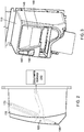
- FIG. 1 illustrates an example implementation of a payment interface bezel 100 and FIG. 2 is a side view of the example implementation of the payment interface bezel 100.
- the payment interface bezel 100 can include a bezel housing 110, which can support one or more media sensors 170 such as a contact reader, a magnetic stripe reader, and the like.
- the payment interface bezel 100 can include a document path 120 for accepting documents such as paper currency and guiding the documents to a document validator 210 for determining the authenticity of the document.
- the payment interface bezel 100 can include a card path 130 for accepting financial transaction cards and guiding the financial transaction cards to media sensors for sensing data contained on the financial transaction cards.
- the payment interface bezel 100 can further include a display 140 and interactive buttons 150 for interfacing with a user, as well as a landing pad 160 for sensing contactless media on a card or other device.
- the document path 120 and the card path 130 intersect (e.g., cross) substantially along their width.
- the card path 130 and document path 120 can cross substantially perpendicular to one another.
- Such configurations can provide for a compact (in size) payment interface bezel 100.
- the card path 130 and the document path 120 do not intersect.
- a gate 180 can be included in the payment interface bezel 100.
- the gate 180 can be configured to allow objects or items shaped like financial transaction cards (e.g., credit cards) to pass through the card path 130 while inhibiting non-card or non-acceptable shaped objects (such as coins, keys, or other objects) from traveling the full length of the card path 130.
- the gate 180 separates the card path 130 from the document path 120.
- the gate 180 is closed, which allows documents to be freely accepted and paid out through the document path 120.
- the gate 180 can move (e.g., slide, translate, rotate, and/or the like) open, allowing the customer to swipe the card.
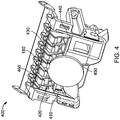
- FIG. 4 is a cutaway view of the example implementation of the payment interface bezel 100 with a gate 180 that can discriminate between a card and a non-card or non-acceptable object, such as a coin.
- FIG. 5 is a cross section view of the example implementation of the payment interface bezel 100 with gate 180 illustrated in FIG. 4 .
- the gate 180 can be mounted or coupled to a housing 410.
- the gate 180 and the housing 410 can form a gate assembly 400.
- the housing 410 can define a portion of the card path 130 (e.g., a portion of a side of the card path 130 can comprise the housing 410) such that a card or other object traveling through the card path 130 passes the gate 180.
- the gate 180 is illustrated in a closed position.
- the gate 180 can include a main body 420 mounted or coupled to the housing 410 and movable between the closed position and the open position.
- the main body 420 can move between the closed position and the open position by rotating; however, other mounts are possible, such as sliding, translating, and the like.
- Hook members 430 can extend from the main body 420 and, when the gate 180 is in the closed position, the hook members 430 can extend into the card path 130.
- the hook members 430 can be oriented and/or shaped to catch or inhibit objects, such as coin 450, traveling through the card path 130 when the gate 180 is in the closed position.
- the hook members 430 can be curved or straight (e.g., members or blocking members).
- each of the one or more hook members 430 is a projection curving towards the entrance of the card path 130.
- the gate 180 can include an activation rib 440 extending from the main body 420.
- the activation rib 440 can extend into the card path 130.
- the activation rib 440 can be coupled to the main body 420 so force applied to the activation rib actuates the gate 180 from the closed position to an open position, which can withdraw the hook members 430 from the card path 130.
- the force can be applied by an object moving through the card path 130 (e.g., the object can push on the activation rib 440 to actuate the gate 180 between closed and open positions).
- objects can pass uninhibited by the gate 180 down the card path 130 past the gate 180.
- the activation rib 440 can be located substantially on an edge or side of the card path 130. Such location can allow the gate 180 to discriminate between card-shaped objects and non-acceptable or non-card objects based on a width of the object or item being inserted into the card path 130. For example, as illustrated in the example implementation of FIG. 4 , the activation rib 440 is located substantially on the edge of the card path 130. Because the coin 450 is of a sufficient size and is round, the coin 450 cannot (or has a small chance to) contact the activation rib 440.
- Gate 180 can include arm members 460 that can extend from the main body 420 and/or the hook members 430. When the gate 180 is in the closed position, the arm members 460 can separate the document path 120 from the card path 130 near the intersection of the two paths. The arm members 460 can have a smooth side for allowing a document to traverse the document path 120 when the main body 420 is in the closed position and prevent a document from catching on a slot or opening created by the intersection with the card path 130. When the gate 180 is in the open position, the arm members 460 can rotate to block the document path 120. Thus the gate 180 can ensure that a document and a card cannot be inserted simultaneously. (E.g., when one of the two paths is in use, the other path can become inoperable).
- the arm members 460 do not block the document path 120 when the gate 180 is in the open position.
- a document in the document path 120 can prevent a card from being fully inserted into the card path 130, and a card in the card path 130 can prevent a document from being fully inserted into the document path 120.
- FIG. 6 is a front view of a portion of the example payment interface bezel 100 illustrated in FIGs. 4-5 , in which a coin has been inserted into the card path 130.
- the bezel housing 110 can include geometry (as indicated at 610) or a second housing for guiding a coin 450 or other non-acceptable item away from the activation rib 440.
- the bezel housing 110 geometry can be shaped so that a user does not have clearance to insert a coin sufficiently far enough down the card path 130 along one side of the card path 130 to actuate the activation rib 440 and thereby open the gate 180 (at least without additional coins and/or objects being inserted into the card path 130).
- FIG. 7 is a cutaway view of the example implementation of the payment interface bezel 100 illustrating the gate 180 being actuated by a credit card 710.
- the credit card 710 has been inserted into the card path 130 and is applying a force on the activation rib 440. Because the credit card 710 is substantially the width of the card path 130, the credit card 710 contacts the activation rib 440 before contacting and being inhibited by the hook members 430.
- FIG. 8 is a cross-section view of a portion of the example implementation of the payment interface bezel 100 illustrating a credit card 810 having actuated the gate 180 into the open position and a leading edge of the credit card 810 having traveled just past the gate 180.
- FIG. 3 is a front perspective view thereof.
- the activation rib 440 can include a smooth ramp surface 820 for contacting the leading edge of the credit card 810 and allowing the gate 180 to move (e.g., rotate, translate, slide, and the like) from the close position to the open position.
- the gate 180 can include a spring bias to transition the gate 180 from the open position to the closed position when a card is removed from the card path 130. Other biasing mechanisms are possible.
- FIG. 9 is a cross-section view of another example implementation of a payment interface bezel 900.
- hook members 930 extend from gate 180 main body 920 and completely traverse the card path 130.
- a locking feature 940 can be included on the card path 130 opposite the gate 980. The locking feature 940 can provide additional support to the gate 180 for resisting insertion of a non-acceptable.
- the payment interface bezel 900 can include a bezel housing 905 coupled to a gate housing 910.
- the gate 980 can be movably mounted or coupled to the gate housing 910.
- the financial transaction card media type can be any media type suitable for inputting, storing, outputting, and updating data on a standardized financial transaction card.
- the media type can include magnetic stripes, integrated chips, integrated chips and pins, radio frequency (RF) devices, near field communication (NFC) devices, and the like.
- Media sensors 170 can include any suitable media sensor appropriate for sensing media types found in standardized financial transaction card.
- suitable media sensors can include magnetic stripe readers, chip readers, chip and pin readers, contactless readers, prepaid card readers, RF readers, NFC readers, and the like.
- a gate can include multiple parts, with a first activation rib substantially near one edge of a card path, and a second activation rib substantially near another (e.g., opposite) edge of the card path.
- Levers can be included with the activation ribs to lock the gate in the closed position until both of the activation ribs are actuated, releasing the levers, and allowing the gate to open.
Landscapes
- Physics & Mathematics (AREA)
- General Physics & Mathematics (AREA)
- Engineering & Computer Science (AREA)
- Theoretical Computer Science (AREA)
- Devices For Checking Fares Or Tickets At Control Points (AREA)
- Control Of Vending Devices And Auxiliary Devices For Vending Devices (AREA)
Description
- The subject matter described herein relates to a gate for a payment interface such as a coin resistant card slot gate for a payment interface.
- Electronic transaction systems, such as an automatic ticket seller machine, automatic teller machine, vending machine, and other kiosks are provided at unattended places to provide ease and flexibility to a user to perform transactions in return for goods or services. In addition to paper money and coins, many of these machines will accept standard financial transaction cards, such as credit cards, bank cards, gifts cards, and the like. Such machines can have payment interfaces with multiple openings for different payment types. For example, a different opening can be provided for coin, banknote, and financial transaction card.
- But users may inadvertently insert a payment into the wrong opening, such as inserting a coin into the opening provided for a financial transaction card, which may jam the system and can make the system inoperative. The jam is compounded if another subsequent user attempts to swipe a card after a coin becomes lodged in the financial transaction opening, since the card can push the coins even further into the opening. Coins (or other non-financial transaction card objects) stuck in the card opening may require a service call to remove. If the coins are jammed far enough into the opening, nearly complete disassembly of the payment interface can be required to remove the coins.
-
US 6,186,401 B1 discloses an apparatus that can pass the front portion of a smart card to a card reader, while safeguarding the card reader from vandalism. A gate device whose front end can be pivoted up by the leading edge of the card, is initially prevented from pivoting up by a pair of release members lying within laterally opposite sides of the card path. Opposite corners of the card leading edge push the release members laterally out of the card path and causes the release members to release the card gate to pivot up. - The present invention relates to a gate as defined in
claim 1, a gate assembly as defined in claim 4 and a payment interface bezel as defined in claim 10. The gate assembly includes a housing, a main body, at least one member, and an activation rib. The housing defines at least a portion of a card path of a payment interface. The main body is coupled to the housing and is movable between a closed position and an open position. The at least one member extends from the main body such that, when the main body is in the closed position, the at least one member extends into the card path and is oriented to inhibit an item from traveling through the card path. The activation rib extends from and is integral with the main body and is located such that, when the main body is in the closed position, the activation rib extends into the card path. The activation rib is coupled to the main body so force applied to the activation rib actuates the main body from the closed position to the open position. - The gate includes a main body, at least one member, and an activation rib. The main body is capable of coupling to a housing of a payment interface and moving between a closed position and an open position. The at least one member extends from the main body such that, when the main body is in the closed position, the at least one member extends into a card path defined by the housing of the payment interface. The at least one member is oriented to inhibit an item from traveling through the card path. The activation rib extends from and is integral with the main body and is located such that, when the main body is in the closed position, the activation rib extends into the card path. The activation rib is coupled to the main body so force applied to the activation rib actuates the main body from the closed position to the open position.
- The payment interface bezel includes a media sensor, a display, an interactive button for interfacing with a user, a bezel housing, and a gate assembly. The bezel housing supports the media sensor and defines a card path for guiding financial transaction cards to the media sensor. The bezel housing defines a document path for guiding a document to a document validator for verifying authenticity of the document. The gate assembly includes a housing, a main body, at least one member, and an activation rib. The housing defines at least a portion of the card path. The main body is coupled to the housing and movable between a closed position and an open position. The at least one member extends from the main body such that, when the main body is in the closed position, the at least one member extends into the card path and is oriented to inhibit an item from traveling through the card path. The activation rib extends from and is integral with the main body and is located such that, when the main body is in the closed position, the activation rib extends into the card path. The activation rib is coupled to the main body so force applied to the activation rib actuates the main body from the closed position to the open position.
- One or more of the following features can be included in any feasible combination. For example, the activation rib can be located to discriminate between a card item and a non-card item. The non-card item can be a coin. The activation rib can be located substantially on an edge of the card path. The housing can further define a document path and the document path can intersect the card path at an intersection. One or more arm members can be included that are coupled to the main body and can separate the document path from the card path near the intersection when the main body is in the closed position. The one or more arm members can have a smooth side for allowing a document to traverse the document path when the main body is in the closed position. The activation rib can have a smooth ramp surface. A bezel housing can be included that guides a non-card item away from the activation rib. A bezel housing can be included having a locking feature configured to interface with the at least one member and the at least one member can be configured to completely traverse the card path when the main body is in the closed position.
- The subject matter described herein can provide many advantages. For example, no software or electronics may be required to discriminate between card and non-card objects (such as optical sensors to discriminate between acceptable and non-acceptable cards). Additionally, the current subject matter can be installed in existing payment interface devices to enable retrofitting of the existing payment interface and reduce the need to completely replace the payment interface. Moreover, in some implementations, an object inserted in the card path does not need to be partially accepted before attempting to reject the object so unwanted objects can be prevented from entering a card path relatively closer to the entrance of the card path to reduce likelihood of jamming in the card path.
- The details of one or more variations of the subject matter described herein are set forth in the accompanying drawings and the description below. Other features and advantages of the subject matter described herein will be apparent from the description and drawings, and from the claims.
-
-
FIG. 1 is a front perspective view of an example implementation of a payment interface bezel; -
FIG. 2 is a side view of the example implementation of the payment interface bezel; -
FIG. 3 is a front perspective of the example implementation of the payment interface bezel illustrating a credit card having actuated a gate into an open position; -
FIG. 4 is a cutaway view of the example implementation of the payment interface bezel with a gate that can discriminate between a card and a non-card or non-acceptable object, such as a coin; -
FIG. 5 is a cross section view of the example implementation of the payment interface bezel with gate illustrated inFIG. 4 ; -
FIG. 6 is a front view of a portion of the example payment interface bezel illustrated inFIGs. 4-5 , in which a coin has been inserted into the card path; -
FIG. 7 is a cutaway view of the example implementation of the payment interface bezel illustrating the gate being actuated by a credit card; -
FIG. 8 is a cross-section view of a portion of the example implementation of the payment interface bezel illustrating a credit card having actuated gate into the open position; and -
FIG. 9 is a cross-section view of another example implementation of a payment interface bezel. - Like reference symbols in the various drawings indicate like elements.
- Described herein is a gate for a payment interface for distinguishing between financial transaction cards (e.g., credit cards) and non-card or non-acceptable objects, such as coins, keys, or other objects. The gate can prevent insertion of non-acceptable objects into a card path of a card reader.
-
FIG. 1 illustrates an example implementation of apayment interface bezel 100 andFIG. 2 is a side view of the example implementation of thepayment interface bezel 100. Thepayment interface bezel 100 can include abezel housing 110, which can support one ormore media sensors 170 such as a contact reader, a magnetic stripe reader, and the like. Thepayment interface bezel 100 can include adocument path 120 for accepting documents such as paper currency and guiding the documents to adocument validator 210 for determining the authenticity of the document. Thepayment interface bezel 100 can include acard path 130 for accepting financial transaction cards and guiding the financial transaction cards to media sensors for sensing data contained on the financial transaction cards. Thepayment interface bezel 100 can further include adisplay 140 andinteractive buttons 150 for interfacing with a user, as well as alanding pad 160 for sensing contactless media on a card or other device. - In the example implementation illustrated in
FIG. 1 andFIG. 2 , thedocument path 120 and thecard path 130 intersect (e.g., cross) substantially along their width. In some example implementations, thecard path 130 anddocument path 120 can cross substantially perpendicular to one another. Such configurations can provide for a compact (in size)payment interface bezel 100. And in some other example implementations, thecard path 130 and thedocument path 120 do not intersect. - A
gate 180 can be included in thepayment interface bezel 100. Thegate 180 can be configured to allow objects or items shaped like financial transaction cards (e.g., credit cards) to pass through thecard path 130 while inhibiting non-card or non-acceptable shaped objects (such as coins, keys, or other objects) from traveling the full length of thecard path 130. In some example implementations, thegate 180 separates thecard path 130 from thedocument path 120. When no card is present, thegate 180 is closed, which allows documents to be freely accepted and paid out through thedocument path 120. When a user (e.g., a customer) presents a card, thegate 180 can move (e.g., slide, translate, rotate, and/or the like) open, allowing the customer to swipe the card. -
FIG. 4 is a cutaway view of the example implementation of thepayment interface bezel 100 with agate 180 that can discriminate between a card and a non-card or non-acceptable object, such as a coin.FIG. 5 is a cross section view of the example implementation of thepayment interface bezel 100 withgate 180 illustrated inFIG. 4 . Thegate 180 can be mounted or coupled to ahousing 410. Thegate 180 and thehousing 410 can form agate assembly 400. Thehousing 410 can define a portion of the card path 130 (e.g., a portion of a side of thecard path 130 can comprise the housing 410) such that a card or other object traveling through thecard path 130 passes thegate 180. InFIG. 4 , thegate 180 is illustrated in a closed position. - The
gate 180 can include amain body 420 mounted or coupled to thehousing 410 and movable between the closed position and the open position. In the example implementation illustrated inFIG. 4 , themain body 420 can move between the closed position and the open position by rotating; however, other mounts are possible, such as sliding, translating, and the like.Hook members 430 can extend from themain body 420 and, when thegate 180 is in the closed position, thehook members 430 can extend into thecard path 130. Thehook members 430 can be oriented and/or shaped to catch or inhibit objects, such ascoin 450, traveling through thecard path 130 when thegate 180 is in the closed position. Thehook members 430 can be curved or straight (e.g., members or blocking members). In the example implementation, each of the one ormore hook members 430 is a projection curving towards the entrance of thecard path 130. - The
gate 180 can include anactivation rib 440 extending from themain body 420. When thegate 180 is in the closed position, theactivation rib 440 can extend into thecard path 130. Theactivation rib 440 can be coupled to themain body 420 so force applied to the activation rib actuates thegate 180 from the closed position to an open position, which can withdraw thehook members 430 from thecard path 130. The force can be applied by an object moving through the card path 130 (e.g., the object can push on theactivation rib 440 to actuate thegate 180 between closed and open positions). When thehook members 430 are withdrawn from thecard path 130, objects can pass uninhibited by thegate 180 down thecard path 130 past thegate 180. - The
activation rib 440 can be located substantially on an edge or side of thecard path 130. Such location can allow thegate 180 to discriminate between card-shaped objects and non-acceptable or non-card objects based on a width of the object or item being inserted into thecard path 130. For example, as illustrated in the example implementation ofFIG. 4 , theactivation rib 440 is located substantially on the edge of thecard path 130. Because thecoin 450 is of a sufficient size and is round, thecoin 450 cannot (or has a small chance to) contact theactivation rib 440. -
Gate 180 can includearm members 460 that can extend from themain body 420 and/or thehook members 430. When thegate 180 is in the closed position, thearm members 460 can separate thedocument path 120 from thecard path 130 near the intersection of the two paths. Thearm members 460 can have a smooth side for allowing a document to traverse thedocument path 120 when themain body 420 is in the closed position and prevent a document from catching on a slot or opening created by the intersection with thecard path 130. When thegate 180 is in the open position, thearm members 460 can rotate to block thedocument path 120. Thus thegate 180 can ensure that a document and a card cannot be inserted simultaneously. (E.g., when one of the two paths is in use, the other path can become inoperable). In some implementations, thearm members 460 do not block thedocument path 120 when thegate 180 is in the open position. A document in thedocument path 120 can prevent a card from being fully inserted into thecard path 130, and a card in thecard path 130 can prevent a document from being fully inserted into thedocument path 120. -
FIG. 6 is a front view of a portion of the examplepayment interface bezel 100 illustrated inFIGs. 4-5 , in which a coin has been inserted into thecard path 130. Thebezel housing 110 can include geometry (as indicated at 610) or a second housing for guiding acoin 450 or other non-acceptable item away from theactivation rib 440. Thebezel housing 110 geometry can be shaped so that a user does not have clearance to insert a coin sufficiently far enough down thecard path 130 along one side of thecard path 130 to actuate theactivation rib 440 and thereby open the gate 180 (at least without additional coins and/or objects being inserted into the card path 130). -
FIG. 7 is a cutaway view of the example implementation of thepayment interface bezel 100 illustrating thegate 180 being actuated by acredit card 710. Thecredit card 710 has been inserted into thecard path 130 and is applying a force on theactivation rib 440. Because thecredit card 710 is substantially the width of thecard path 130, thecredit card 710 contacts theactivation rib 440 before contacting and being inhibited by thehook members 430. -
FIG. 8 is a cross-section view of a portion of the example implementation of thepayment interface bezel 100 illustrating acredit card 810 having actuated thegate 180 into the open position and a leading edge of thecredit card 810 having traveled just past thegate 180.FIG. 3 is a front perspective view thereof. As seen inFIG. 8 , theactivation rib 440 can include asmooth ramp surface 820 for contacting the leading edge of thecredit card 810 and allowing thegate 180 to move (e.g., rotate, translate, slide, and the like) from the close position to the open position. - The
gate 180 can include a spring bias to transition thegate 180 from the open position to the closed position when a card is removed from thecard path 130. Other biasing mechanisms are possible. -
FIG. 9 is a cross-section view of another example implementation of apayment interface bezel 900. In this example implementation,hook members 930 extend fromgate 180main body 920 and completely traverse thecard path 130. Alocking feature 940 can be included on thecard path 130 opposite thegate 980. Thelocking feature 940 can provide additional support to thegate 180 for resisting insertion of a non-acceptable. Thepayment interface bezel 900 can include abezel housing 905 coupled to agate housing 910. Thegate 980 can be movably mounted or coupled to thegate housing 910. - The financial transaction card media type can be any media type suitable for inputting, storing, outputting, and updating data on a standardized financial transaction card. The media type can include magnetic stripes, integrated chips, integrated chips and pins, radio frequency (RF) devices, near field communication (NFC) devices, and the like.
Media sensors 170 can include any suitable media sensor appropriate for sensing media types found in standardized financial transaction card. For example, suitable media sensors can include magnetic stripe readers, chip readers, chip and pin readers, contactless readers, prepaid card readers, RF readers, NFC readers, and the like. - In some implementations, multiple activation ribs can be included with the gate. For example, a gate can include multiple parts, with a first activation rib substantially near one edge of a card path, and a second activation rib substantially near another (e.g., opposite) edge of the card path. Levers can be included with the activation ribs to lock the gate in the closed position until both of the activation ribs are actuated, releasing the levers, and allowing the gate to open.
- Although a few variations have been described in detail above, other modifications are possible. For example, the implementations described above can be directed to various combinations and subcombinations of the disclosed features and/or combinations and subcombinations of several further features disclosed above. In addition, the logic flows described herein do not require the particular order shown, or sequential order, to achieve desirable results. Other embodiments may be within the scope of the following claims.
Claims (11)
- A gate comprising:a main body (420) capable of coupling to a housing (410) of a payment interface and moving between a closed position and an open position;at least one member (430) extending from the main body (420) such that, when the main body (420) is in the closed position, the at least one member (430) extends into a card path (130) defined by the housing (410) of the payment interface, the at least one member (430) oriented to inhibit an item from traveling through the card path (130); andcharacterized by an activation rib (440) extending from and being integral with the main body (420) and located such that, when the main body (420) is in the closed position, the activation rib (440) extends into the card path (130), the activation rib (440) coupled to the main body (420) so force applied to the activation rib (440) actuates the main body (420) from the closed position to the open position.
- The gate of claim 1 wherein the activation rib (440) is located to discriminate between a card item and a non-card item.
- The gate of claim 2, wherein the activation rib (440) is located substantially on an edge of the card path (130).
- A gate assembly comprising:a housing (410) defining at least a portion of a card path (130) of a payment interface; anda gate according to any one of claims 1 to 3, wherein the main body (420) is coupled to the housing (410).
- The gate assembly of claim 4, wherein the housing (410) further defines a document path (120) and the document path (130) intersects the card path (130) at an intersection.
- The gate assembly of claim 5, further comprising one or more arm members (460) coupled to the main body (420) and separating the document path (120) from the card path (130) near the intersection when the main body (420) is in the closed position, the one or more arm members (460) having a smooth side for allowing a document to traverse the document path (120) when the main body (420) is in the closed position.
- The gate assembly of claim 4, wherein the activation rib (440) has a smooth ramp surface.
- The gate assembly of claim 4, further comprising a bezel housing (110) that guides a non-card item away from the activation rib (440).
- The gate assembly of claim 4, further comprising a bezel housing (110) with a locking feature (940) configured to interface with the at least one member (930), the at least one member (930) configured to completely traverse the card path (130) when the main body (920) is in the closed position.
- A payment interface bezel comprising:a media sensor (170);a display (140);an interactive button (150) for interfacing with a user;a bezel housing (110) supporting the media sensor (170) and defining a card path (130) for guiding financial transaction cards to the media sensor (170), the bezel housing (110) further defining a document path (120) for guiding a document to a document validator (210) for verifying authenticity of the document; anda gate assembly according to any one of claims 4 to 9.
- The payment interface bezel of claim 10, further comprising one or more arm members coupled to the main body and separating the document path from the card path near an intersection between the card path and the document path when the main body is in the closed position, the one or more arm members having a smooth side for allowing the document to traverse the document path when the main body is in the closed position.
Applications Claiming Priority (1)
| Application Number | Priority Date | Filing Date | Title |
|---|---|---|---|
| US14/281,035 US9792536B2 (en) | 2014-05-19 | 2014-05-19 | Gate for a payment interface |
Publications (2)
| Publication Number | Publication Date |
|---|---|
| EP2947605A1 EP2947605A1 (en) | 2015-11-25 |
| EP2947605B1 true EP2947605B1 (en) | 2019-09-11 |
Family
ID=53177250
Family Applications (1)
| Application Number | Title | Priority Date | Filing Date |
|---|---|---|---|
| EP15167866.1A Active EP2947605B1 (en) | 2014-05-19 | 2015-05-15 | Gate for a payment interface |
Country Status (5)
| Country | Link |
|---|---|
| US (1) | US9792536B2 (en) |
| EP (1) | EP2947605B1 (en) |
| CN (1) | CN105225342B (en) |
| CA (1) | CA2891780A1 (en) |
| ES (1) | ES2750954T3 (en) |
Families Citing this family (3)
| Publication number | Priority date | Publication date | Assignee | Title |
|---|---|---|---|---|
| CN108346215B (en) * | 2017-02-23 | 2020-06-19 | 深圳市铭特科技有限公司 | A device for preventing magnetic stripe cards from being stolen and swiped |
| WO2020041586A1 (en) * | 2018-08-23 | 2020-02-27 | Crane Payment Innovations, Inc. | Dual rib coin resistant gate for a payment interface |
| USD889765S1 (en) | 2018-08-27 | 2020-07-07 | Crane Payment Innovations, Inc. | Bezel |
Family Cites Families (9)
| Publication number | Priority date | Publication date | Assignee | Title |
|---|---|---|---|---|
| US3766687A (en) * | 1972-02-16 | 1973-10-23 | Docutel Corp | Apparatus for entry control |
| JPH05303821A (en) | 1992-04-24 | 1993-11-16 | Olympus Optical Co Ltd | Recording and reproducing device for card-like recording medium |
| US5791449A (en) * | 1996-05-30 | 1998-08-11 | Mars Incorporated | Bezel for a vending machine |
| US5831862A (en) * | 1996-08-05 | 1998-11-03 | Mars, Incorporated | Automatic transaction system with a dynamic display and methods of its operation |
| US5905252A (en) * | 1997-11-24 | 1999-05-18 | Itt Manufacturing Enterprises, Inc. | Card gate mechanism |
| GB2352552A (en) | 1999-07-23 | 2001-01-31 | Ncr Int Inc | Access control for a self-service terminal |
| JP3898488B2 (en) * | 2001-11-16 | 2007-03-28 | 株式会社日本コンラックス | Banknote processing device with credit card reader |
| JP5179924B2 (en) * | 2008-03-31 | 2013-04-10 | 日本電産サンキョー株式会社 | Card reader shutter mechanism and card reader |
| BR302012005796S1 (en) | 2012-05-08 | 2014-10-29 | Mei Inc | CONFIGURATION APPLIED ON SALES MACHINE. |
-
2014
- 2014-05-19 US US14/281,035 patent/US9792536B2/en active Active
-
2015
- 2015-05-14 CA CA2891780A patent/CA2891780A1/en not_active Abandoned
- 2015-05-15 EP EP15167866.1A patent/EP2947605B1/en active Active
- 2015-05-15 ES ES15167866T patent/ES2750954T3/en active Active
- 2015-05-19 CN CN201510458201.0A patent/CN105225342B/en not_active Expired - Fee Related
Non-Patent Citations (1)
| Title |
|---|
| None * |
Also Published As
| Publication number | Publication date |
|---|---|
| ES2750954T3 (en) | 2020-03-30 |
| CA2891780A1 (en) | 2015-11-19 |
| US20150332130A1 (en) | 2015-11-19 |
| EP2947605A1 (en) | 2015-11-25 |
| CN105225342A (en) | 2016-01-06 |
| CN105225342B (en) | 2020-01-07 |
| US9792536B2 (en) | 2017-10-17 |
Similar Documents
| Publication | Publication Date | Title |
|---|---|---|
| CN101145256B (en) | Value medium processing device | |
| US6491216B1 (en) | Security system | |
| EP2509052B1 (en) | Banknote depositing and dispensing apparatus | |
| US8678163B2 (en) | Paper currency handling apparatus and method of depositing paper currencies using same | |
| CN101739751B (en) | Automatic transaction device and control method thereof | |
| CN102119404A (en) | Banknote ATM | |
| US9792536B2 (en) | Gate for a payment interface | |
| JP2008071088A5 (en) | ||
| CN103793991B (en) | Bank note treatment device and paper currency detecting method | |
| JP6378537B2 (en) | Coin collecting member and coin processing apparatus with collecting member | |
| JP6331813B2 (en) | Cash processing equipment | |
| US12086662B2 (en) | Dual rib coin resistant gate for a payment interface | |
| JP4376074B2 (en) | Coin handling apparatus and change management system using the same | |
| JP4611344B2 (en) | Automatic transaction equipment | |
| JP6208032B2 (en) | Automatic transaction apparatus, state management method and management system | |
| JP7835319B1 (en) | Money processing system and money processing device | |
| JP7549073B2 (en) | Valuable media processing equipment | |
| JP2014089633A (en) | Bill processor | |
| JP2016194747A (en) | Coin processing apparatus and processing system | |
| JP2020135661A (en) | Card handling device and paper sheet processing device | |
| JP5582222B2 (en) | Banknote deposit and withdrawal machine | |
| WO2015069132A1 (en) | Device for dispensing and receiving cash and method for using same | |
| JP2011043880A (en) | Ic coin changer |
Legal Events
| Date | Code | Title | Description |
|---|---|---|---|
| PUAI | Public reference made under article 153(3) epc to a published international application that has entered the european phase |
Free format text: ORIGINAL CODE: 0009012 |
|
| 17P | Request for examination filed |
Effective date: 20150515 |
|
| AK | Designated contracting states |
Kind code of ref document: A1 Designated state(s): AL AT BE BG CH CY CZ DE DK EE ES FI FR GB GR HR HU IE IS IT LI LT LU LV MC MK MT NL NO PL PT RO RS SE SI SK SM TR |
|
| AX | Request for extension of the european patent |
Extension state: BA ME |
|
| 17Q | First examination report despatched |
Effective date: 20151130 |
|
| RAP1 | Party data changed (applicant data changed or rights of an application transferred) |
Owner name: CRANE PAYMENT INNOVATIONS, INC. |
|
| GRAP | Despatch of communication of intention to grant a patent |
Free format text: ORIGINAL CODE: EPIDOSNIGR1 |
|
| STAA | Information on the status of an ep patent application or granted ep patent |
Free format text: STATUS: GRANT OF PATENT IS INTENDED |
|
| INTG | Intention to grant announced |
Effective date: 20190329 |
|
| RIN1 | Information on inventor provided before grant (corrected) |
Inventor name: CARMINE, CHRISTOPHER STEPHEN |
|
| GRAS | Grant fee paid |
Free format text: ORIGINAL CODE: EPIDOSNIGR3 |
|
| GRAA | (expected) grant |
Free format text: ORIGINAL CODE: 0009210 |
|
| STAA | Information on the status of an ep patent application or granted ep patent |
Free format text: STATUS: THE PATENT HAS BEEN GRANTED |
|
| AK | Designated contracting states |
Kind code of ref document: B1 Designated state(s): AL AT BE BG CH CY CZ DE DK EE ES FI FR GB GR HR HU IE IS IT LI LT LU LV MC MK MT NL NO PL PT RO RS SE SI SK SM TR |
|
| REG | Reference to a national code |
Ref country code: GB Ref legal event code: FG4D |
|
| REG | Reference to a national code |
Ref country code: CH Ref legal event code: EP |
|
| REG | Reference to a national code |
Ref country code: AT Ref legal event code: REF Ref document number: 1179422 Country of ref document: AT Kind code of ref document: T Effective date: 20190915 |
|
| REG | Reference to a national code |
Ref country code: DE Ref legal event code: R096 Ref document number: 602015037621 Country of ref document: DE Ref country code: IE Ref legal event code: FG4D |
|
| REG | Reference to a national code |
Ref country code: NL Ref legal event code: MP Effective date: 20190911 |
|
| REG | Reference to a national code |
Ref country code: LT Ref legal event code: MG4D |
|
| PG25 | Lapsed in a contracting state [announced via postgrant information from national office to epo] |
Ref country code: BG Free format text: LAPSE BECAUSE OF FAILURE TO SUBMIT A TRANSLATION OF THE DESCRIPTION OR TO PAY THE FEE WITHIN THE PRESCRIBED TIME-LIMIT Effective date: 20191211 Ref country code: NO Free format text: LAPSE BECAUSE OF FAILURE TO SUBMIT A TRANSLATION OF THE DESCRIPTION OR TO PAY THE FEE WITHIN THE PRESCRIBED TIME-LIMIT Effective date: 20191211 Ref country code: SE Free format text: LAPSE BECAUSE OF FAILURE TO SUBMIT A TRANSLATION OF THE DESCRIPTION OR TO PAY THE FEE WITHIN THE PRESCRIBED TIME-LIMIT Effective date: 20190911 Ref country code: HR Free format text: LAPSE BECAUSE OF FAILURE TO SUBMIT A TRANSLATION OF THE DESCRIPTION OR TO PAY THE FEE WITHIN THE PRESCRIBED TIME-LIMIT Effective date: 20190911 Ref country code: LT Free format text: LAPSE BECAUSE OF FAILURE TO SUBMIT A TRANSLATION OF THE DESCRIPTION OR TO PAY THE FEE WITHIN THE PRESCRIBED TIME-LIMIT Effective date: 20190911 Ref country code: FI Free format text: LAPSE BECAUSE OF FAILURE TO SUBMIT A TRANSLATION OF THE DESCRIPTION OR TO PAY THE FEE WITHIN THE PRESCRIBED TIME-LIMIT Effective date: 20190911 |
|
| PG25 | Lapsed in a contracting state [announced via postgrant information from national office to epo] |
Ref country code: LV Free format text: LAPSE BECAUSE OF FAILURE TO SUBMIT A TRANSLATION OF THE DESCRIPTION OR TO PAY THE FEE WITHIN THE PRESCRIBED TIME-LIMIT Effective date: 20190911 Ref country code: GR Free format text: LAPSE BECAUSE OF FAILURE TO SUBMIT A TRANSLATION OF THE DESCRIPTION OR TO PAY THE FEE WITHIN THE PRESCRIBED TIME-LIMIT Effective date: 20191212 Ref country code: RS Free format text: LAPSE BECAUSE OF FAILURE TO SUBMIT A TRANSLATION OF THE DESCRIPTION OR TO PAY THE FEE WITHIN THE PRESCRIBED TIME-LIMIT Effective date: 20190911 Ref country code: AL Free format text: LAPSE BECAUSE OF FAILURE TO SUBMIT A TRANSLATION OF THE DESCRIPTION OR TO PAY THE FEE WITHIN THE PRESCRIBED TIME-LIMIT Effective date: 20190911 |
|
| REG | Reference to a national code |
Ref country code: ES Ref legal event code: FG2A Ref document number: 2750954 Country of ref document: ES Kind code of ref document: T3 Effective date: 20200330 |
|
| REG | Reference to a national code |
Ref country code: AT Ref legal event code: MK05 Ref document number: 1179422 Country of ref document: AT Kind code of ref document: T Effective date: 20190911 |
|
| PG25 | Lapsed in a contracting state [announced via postgrant information from national office to epo] |
Ref country code: NL Free format text: LAPSE BECAUSE OF FAILURE TO SUBMIT A TRANSLATION OF THE DESCRIPTION OR TO PAY THE FEE WITHIN THE PRESCRIBED TIME-LIMIT Effective date: 20190911 Ref country code: AT Free format text: LAPSE BECAUSE OF FAILURE TO SUBMIT A TRANSLATION OF THE DESCRIPTION OR TO PAY THE FEE WITHIN THE PRESCRIBED TIME-LIMIT Effective date: 20190911 Ref country code: EE Free format text: LAPSE BECAUSE OF FAILURE TO SUBMIT A TRANSLATION OF THE DESCRIPTION OR TO PAY THE FEE WITHIN THE PRESCRIBED TIME-LIMIT Effective date: 20190911 Ref country code: RO Free format text: LAPSE BECAUSE OF FAILURE TO SUBMIT A TRANSLATION OF THE DESCRIPTION OR TO PAY THE FEE WITHIN THE PRESCRIBED TIME-LIMIT Effective date: 20190911 Ref country code: PT Free format text: LAPSE BECAUSE OF FAILURE TO SUBMIT A TRANSLATION OF THE DESCRIPTION OR TO PAY THE FEE WITHIN THE PRESCRIBED TIME-LIMIT Effective date: 20200113 Ref country code: PL Free format text: LAPSE BECAUSE OF FAILURE TO SUBMIT A TRANSLATION OF THE DESCRIPTION OR TO PAY THE FEE WITHIN THE PRESCRIBED TIME-LIMIT Effective date: 20190911 |
|
| PG25 | Lapsed in a contracting state [announced via postgrant information from national office to epo] |
Ref country code: SK Free format text: LAPSE BECAUSE OF FAILURE TO SUBMIT A TRANSLATION OF THE DESCRIPTION OR TO PAY THE FEE WITHIN THE PRESCRIBED TIME-LIMIT Effective date: 20190911 Ref country code: IS Free format text: LAPSE BECAUSE OF FAILURE TO SUBMIT A TRANSLATION OF THE DESCRIPTION OR TO PAY THE FEE WITHIN THE PRESCRIBED TIME-LIMIT Effective date: 20200224 Ref country code: CZ Free format text: LAPSE BECAUSE OF FAILURE TO SUBMIT A TRANSLATION OF THE DESCRIPTION OR TO PAY THE FEE WITHIN THE PRESCRIBED TIME-LIMIT Effective date: 20190911 Ref country code: SM Free format text: LAPSE BECAUSE OF FAILURE TO SUBMIT A TRANSLATION OF THE DESCRIPTION OR TO PAY THE FEE WITHIN THE PRESCRIBED TIME-LIMIT Effective date: 20190911 |
|
| REG | Reference to a national code |
Ref country code: DE Ref legal event code: R097 Ref document number: 602015037621 Country of ref document: DE |
|
| PLBE | No opposition filed within time limit |
Free format text: ORIGINAL CODE: 0009261 |
|
| STAA | Information on the status of an ep patent application or granted ep patent |
Free format text: STATUS: NO OPPOSITION FILED WITHIN TIME LIMIT |
|
| PG2D | Information on lapse in contracting state deleted |
Ref country code: IS |
|
| PG25 | Lapsed in a contracting state [announced via postgrant information from national office to epo] |
Ref country code: DK Free format text: LAPSE BECAUSE OF FAILURE TO SUBMIT A TRANSLATION OF THE DESCRIPTION OR TO PAY THE FEE WITHIN THE PRESCRIBED TIME-LIMIT Effective date: 20190911 Ref country code: IS Free format text: LAPSE BECAUSE OF FAILURE TO SUBMIT A TRANSLATION OF THE DESCRIPTION OR TO PAY THE FEE WITHIN THE PRESCRIBED TIME-LIMIT Effective date: 20200112 |
|
| 26N | No opposition filed |
Effective date: 20200615 |
|
| PG25 | Lapsed in a contracting state [announced via postgrant information from national office to epo] |
Ref country code: SI Free format text: LAPSE BECAUSE OF FAILURE TO SUBMIT A TRANSLATION OF THE DESCRIPTION OR TO PAY THE FEE WITHIN THE PRESCRIBED TIME-LIMIT Effective date: 20190911 |
|
| PG25 | Lapsed in a contracting state [announced via postgrant information from national office to epo] |
Ref country code: CH Free format text: LAPSE BECAUSE OF NON-PAYMENT OF DUE FEES Effective date: 20200531 Ref country code: LI Free format text: LAPSE BECAUSE OF NON-PAYMENT OF DUE FEES Effective date: 20200531 Ref country code: MC Free format text: LAPSE BECAUSE OF FAILURE TO SUBMIT A TRANSLATION OF THE DESCRIPTION OR TO PAY THE FEE WITHIN THE PRESCRIBED TIME-LIMIT Effective date: 20190911 |
|
| REG | Reference to a national code |
Ref country code: BE Ref legal event code: MM Effective date: 20200531 |
|
| PG25 | Lapsed in a contracting state [announced via postgrant information from national office to epo] |
Ref country code: LU Free format text: LAPSE BECAUSE OF NON-PAYMENT OF DUE FEES Effective date: 20200515 |
|
| PG25 | Lapsed in a contracting state [announced via postgrant information from national office to epo] |
Ref country code: IE Free format text: LAPSE BECAUSE OF NON-PAYMENT OF DUE FEES Effective date: 20200515 Ref country code: FR Free format text: LAPSE BECAUSE OF NON-PAYMENT OF DUE FEES Effective date: 20200531 |
|
| PG25 | Lapsed in a contracting state [announced via postgrant information from national office to epo] |
Ref country code: BE Free format text: LAPSE BECAUSE OF NON-PAYMENT OF DUE FEES Effective date: 20200531 |
|
| PG25 | Lapsed in a contracting state [announced via postgrant information from national office to epo] |
Ref country code: TR Free format text: LAPSE BECAUSE OF FAILURE TO SUBMIT A TRANSLATION OF THE DESCRIPTION OR TO PAY THE FEE WITHIN THE PRESCRIBED TIME-LIMIT Effective date: 20190911 Ref country code: MT Free format text: LAPSE BECAUSE OF FAILURE TO SUBMIT A TRANSLATION OF THE DESCRIPTION OR TO PAY THE FEE WITHIN THE PRESCRIBED TIME-LIMIT Effective date: 20190911 Ref country code: CY Free format text: LAPSE BECAUSE OF FAILURE TO SUBMIT A TRANSLATION OF THE DESCRIPTION OR TO PAY THE FEE WITHIN THE PRESCRIBED TIME-LIMIT Effective date: 20190911 |
|
| PG25 | Lapsed in a contracting state [announced via postgrant information from national office to epo] |
Ref country code: MK Free format text: LAPSE BECAUSE OF FAILURE TO SUBMIT A TRANSLATION OF THE DESCRIPTION OR TO PAY THE FEE WITHIN THE PRESCRIBED TIME-LIMIT Effective date: 20190911 |
|
| P01 | Opt-out of the competence of the unified patent court (upc) registered |
Effective date: 20230420 |
|
| PGFP | Annual fee paid to national office [announced via postgrant information from national office to epo] |
Ref country code: DE Payment date: 20230321 Year of fee payment: 9 |
|
| REG | Reference to a national code |
Ref country code: DE Ref legal event code: R082 Ref document number: 602015037621 Country of ref document: DE Representative=s name: VENNER SHIPLEY GERMANY LLP, DE |
|
| PGFP | Annual fee paid to national office [announced via postgrant information from national office to epo] |
Ref country code: GB Payment date: 20240321 Year of fee payment: 10 |
|
| PGFP | Annual fee paid to national office [announced via postgrant information from national office to epo] |
Ref country code: ES Payment date: 20240613 Year of fee payment: 10 |
|
| PGFP | Annual fee paid to national office [announced via postgrant information from national office to epo] |
Ref country code: IT Payment date: 20240411 Year of fee payment: 10 |
|
| REG | Reference to a national code |
Ref country code: DE Ref legal event code: R119 Ref document number: 602015037621 Country of ref document: DE |
|
| GBPC | Gb: european patent ceased through non-payment of renewal fee |
Effective date: 20250515 |
|
| PG25 | Lapsed in a contracting state [announced via postgrant information from national office to epo] |
Ref country code: GB Free format text: LAPSE BECAUSE OF NON-PAYMENT OF DUE FEES Effective date: 20250515 |
|
| PG25 | Lapsed in a contracting state [announced via postgrant information from national office to epo] |
Ref country code: DE Free format text: LAPSE BECAUSE OF NON-PAYMENT OF DUE FEES Effective date: 20251202 |
|
| PG25 | Lapsed in a contracting state [announced via postgrant information from national office to epo] |
Ref country code: IT Free format text: LAPSE BECAUSE OF NON-PAYMENT OF DUE FEES Effective date: 20250515 |