EP2947463A1 - Automatic analysis device - Google Patents
Automatic analysis device Download PDFInfo
- Publication number
- EP2947463A1 EP2947463A1 EP14740134.3A EP14740134A EP2947463A1 EP 2947463 A1 EP2947463 A1 EP 2947463A1 EP 14740134 A EP14740134 A EP 14740134A EP 2947463 A1 EP2947463 A1 EP 2947463A1
- Authority
- EP
- European Patent Office
- Prior art keywords
- washing
- probe
- suctioning
- nozzle
- reagent
- Prior art date
- Legal status (The legal status is an assumption and is not a legal conclusion. Google has not performed a legal analysis and makes no representation as to the accuracy of the status listed.)
- Granted
Links
Images







Classifications
-
- G—PHYSICS
- G01—MEASURING; TESTING
- G01N—INVESTIGATING OR ANALYSING MATERIALS BY DETERMINING THEIR CHEMICAL OR PHYSICAL PROPERTIES
- G01N35/00—Automatic analysis not limited to methods or materials provided for in any single one of groups G01N1/00 - G01N33/00; Handling materials therefor
- G01N35/10—Devices for transferring samples or any liquids to, in, or from, the analysis apparatus, e.g. suction devices, injection devices
- G01N35/1004—Cleaning sample transfer devices
-
- G—PHYSICS
- G01—MEASURING; TESTING
- G01N—INVESTIGATING OR ANALYSING MATERIALS BY DETERMINING THEIR CHEMICAL OR PHYSICAL PROPERTIES
- G01N35/00—Automatic analysis not limited to methods or materials provided for in any single one of groups G01N1/00 - G01N33/00; Handling materials therefor
- G01N35/10—Devices for transferring samples or any liquids to, in, or from, the analysis apparatus, e.g. suction devices, injection devices
- G01N35/1002—Reagent dispensers
-
- G—PHYSICS
- G01—MEASURING; TESTING
- G01N—INVESTIGATING OR ANALYSING MATERIALS BY DETERMINING THEIR CHEMICAL OR PHYSICAL PROPERTIES
- G01N35/00—Automatic analysis not limited to methods or materials provided for in any single one of groups G01N1/00 - G01N33/00; Handling materials therefor
- G01N35/10—Devices for transferring samples or any liquids to, in, or from, the analysis apparatus, e.g. suction devices, injection devices
- G01N35/1009—Characterised by arrangements for controlling the aspiration or dispense of liquids
- G01N35/1011—Control of the position or alignment of the transfer device
Definitions
- the present invention relates to an automatic analysis device which analyzes a reagent and a liquid sample such as blood or urine.
- an automatic analysis device such as an automatic biochemical analyzer and an automatic immunoassay analyzer includes a washing tank for washing a probe with washing water after suctioning and discharging a reagent or a target specimen sample.
- a level of contamination of the probe during suctioning of the reagent or the target specimen sample performed by using the probe is in a volume range of approximately 5 mm in which the probe is thrust into the reagent or the sample after the probe detects the liquid surface. Therefore, the range becomes a washing range of the probe.
- the probe needs to be washed over a wide range corresponding to the range from the cap of the reagent to the bottom of the reagent bottle.
- washing range of the probe results in a disadvantage described below.
- a washing time needs to be sufficiently provided.
- a large quantity of washing water adhered onto a side surface of the probe remains. If a succeeding reagent is suctioned through the probe in such a state, it is assumed that the washing water adhered onto the side surface of the probe is mixed in the reagent bottle, thereby leading to dilution of the reagent caused by washing water.
- washing range of the probe is wide (example: a washing range of 80 mm)
- a method of removing washing water adhered onto the side surface of the probe after the probe is washed there is a known method of removing washing water adhered onto the side surface of the probe by moving the probe to a position of a vacuum suctioning tube after being washed at a probe washing position, lowering the probe into the vacuum suctioning tube, and evacuating the inside of the vacuum suctioning tube (PTL 1 and PTL 2).
- the hole diameter of the opening portion of the washing tank is decreased, there is a significant possibility that the reagent or the target specimen sample adhered onto the probe when the probe is lowered into the washing tank before being washed may scatter or adhere onto the vicinity of the opening portion of the washing tank.
- the probe is inserted into the washing tank, there is a high risk in that the vicinity of the opening portion of the washing tank is contaminated by the reagent or the target specimen sample scattered or adhered, and when the probe is lifted in order to dry the probe after being washed in the washing tank, the probe comes into contact with a liquid scattered or adhered onto the vicinity of the opening portion of the washing tank, thereby causing contamination during suctioning of a succeeding liquid.
- An object of the present invention is to realize an automatic analysis device in which a washing effect of a probe is improved by being washed in a short period of time and washing water and the like which may be mixed in during suctioning of a succeeding liquid can be decreased.
- an automatic analysis device including: a probe that suctions a reagent or a sample and discharges the reagent or the sample into a reaction container; a dispensing mechanism that moves the probe vertically and horizontally; a suctioning and discharging mechanism that causes the probe to suction the reagent or the sample and discharges the reagent or the sample into the reaction container; a photometer that analyzes the sample in the reaction container; a throttle portion that forms an opening portion into which the probe is inserted; a washing mechanism that discharges washing water which flows on a top surface of the throttle portion; a drying mechanism that is arranged below the throttle portion and performs vacuum suctioning of washing water; and a controller that controls operations of the dispensing mechanism, the suctioning and discharging mechanism, the washing mechanism, and the drying mechanism.
- a washing tank for washing a probe that suctions a reagent or a sample and discharges the reagent and the sample to a reaction container includes a throttle portion forming an opening portion into which the probe is inserted, a first washing and drying mechanism being arranged near the throttle portion and performing discharging and vacuum suctioning of washing water, a washing portion being formed below the throttle portion, and a second washing and drying mechanism being connected to the washing portion and performing discharging and vacuum suctioning of washing water. Processes of the probe from washing to drying are performed in the same washing tank.
- Fig. 1 is a diagram of a schematic configuration of an automatic analysis device to which the present invention is applied.
- reaction containers 2 are arranged on the circumference of a reaction disk 1.
- a plurality of reagent bottles 10 can be arranged on the circumference of a reagent disk 9.
- detergent bottles 10a can be arranged in the reagent disk 9.
- a sample transportation mechanism 17 for moving a rack 16 mounted with sample containers 15 is installed near the reaction disk 1.
- Reagent dispensing mechanisms 7 and 8 which can rotate and vertically move are installed between the reaction disk 1 and the reagent disk 9, and each of the reagent dispensing mechanisms 7 and 8 includes a reagent probe 7a.
- the reagent probe 7a moves vertically and horizontally by the reagent dispensing mechanism 7 or 8.
- Reagent syringes 18 (suctioning and discharging mechanisms) are respectively connected to the reagent probes 7a.
- the reagent syringes 18 suctions and discharges a reagent through the reagent probes 7a.
- the reagent syringes 18 discharges washing water into the reagent probe 7a and suctions washing water or detergent from the detergent bottle 10a, thereby washing the inside of the reagent probe 7a.
- a sample dispensing mechanism 11 which can rotate and vertically move is installed between the reaction disk 1 and the sample transportation mechanism 17, and the sample dispensing mechanism 11 includes a sample probe 11a.
- Each of sample syringes 19 are connected to the sample probe 11a.
- the sample probe 11a moves horizontally in an arc while being centered around the rotary axis.
- the sample probe 11a moves vertically so as to dispense sample from a sample container to the reaction container 2.
- washing mechanism 3 In the periphery of the reaction disk 1, a washing mechanism 3, a spectrophotometer 4 for analyzing a sample in the reaction container 2, stirring mechanisms 5 and 6, the reagent disk 9, and the sample transportation mechanism 17 are arranged.
- a washing pump 20 is connected to the washing mechanism 3.
- Washing tanks 13, 30, 31, 32, and 33 are respectively arranged above the operation range of the reagent dispensing mechanisms 7 and 8, the sample dispensing mechanism 11, the stirring mechanisms 5 and 6.
- the washing tank 13 is a washing tank for the sample probe 11a
- the washing tanks 30 and 31 are washing tanks for the stirring mechanisms 5 and 6.
- the washing tanks 32 and 33 are washing tanks for the reagent probe 7a and the reagent dispensing probe of the reagent dispensing mechanism 8.
- the sample container 15 contains an inspection sample such as blood and is mounted on the rack 16, thereby being carried by the sample transportation mechanism 17.
- each of the mechanisms is connected to a controller 21, and operational control thereof is performed by the controller 21.
- a cap is attached to a position of a reagent probe suctioning port of the reagent bottle 10 in order to seal the inside thereof.
- the cap is detached when the reagent bottle 10 is set in the automatic analysis device, and then, the reagent bottle 10 is installed in the device.
- a method in which a notch-like hole is bored in the cap and the reagent probe 7a is inserted into a notch portion so as to suction a reagent. Since a slight notch becomes an opening portion of the cap for the reagent bottle 10, contact of the reagent with respect to the air outside is minimized, thereby improving deterioration of the reagent.
- a washing range of the reagent probe 7a becomes the overall range of the reagent probe 7a which is inserted through the cap of the reagent bottle 10 in order to suction a reagent, it is necessary to perform washing over a wide range compared to a case where the reagent bottle 10 includes no cap.
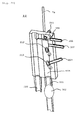
- Fig. 2A is a perspective cross-sectional view of the washing tank 32 according to an exemplary embodiment of the present invention.
- the washing tank 32 is configured to include an electromagnetic valve 302 below a waste liquid portion 221.
- Fig. 3A is a top view of the washing tank 32.
- the cross section taken along line A-A in Fig. 3A is the cross section illustrated in Fig. 2A .
- the washing tank 32 is formed with the structure having the shape illustrated in Fig. 2A and another structure having a shape symmetrical to the illustrated structure. However, a suctioning nozzle 211 described-below is formed in only one structure therebetween.
- the washing tank 33 is also configured to be equivalent to the washing tank 32.
- the reagent probe 7a in order to wash the reagent probe 7a, the reagent probe 7a is lowered into the washing tank 32. Then, the reagent probe 7a passes through an opening portion 303 formed on the top surface of the washing tank 32, and a throttle portion 301 forming a circular opening, thereby being inserted into the washing tank 32.
- the circular opening is an opening (portion) through which the reagent probe 7a is inserted, and the opening (portion) is formed in the throttle portion 301.
- the opening (portion) is not necessarily circular.
- Washing nozzles 202 and 203 are connected to the washing tank 32 so as to supply washing water to the inside of the washing tank 32.
- a channel throttle portion 304 is formed in the opening portion 303.
- the throttle portion 301 includes the opening portion 303 and forms a channel through which washing water discharged from a washing nozzle 201 flows in a horizontal direction.
- the washing nozzle 201 discharges washing water which flows on the top surface of the throttle portion 301.
- the channel width of the channel on a downstream side from an inlet port of the channel throttle portion 304 included in the throttle portion 301 is smaller than the channel width on an upstream side therefrom. It is acceptable that the channel width of the channel on the downstream side from the opening (portion) through which the reagent probe 7a is inserted is smaller than the channel width on the upstream side.
- a washing portion 205 for washing the reagent probe is formed below from the opening portion 303.
- the washing nozzles 202 and 203 are connected to the washing portion 205.
- Washing water is supplied from the washing nozzles 202 and 203 to the washing portion 205 inside the washing tank 32.
- the reagent probe 7a is washed by applying washing water to the reagent probe 7a.
- the electromagnetic valve 302 is in an open state.
- the electromagnetic valve 302 below the waste liquid portion 221 is in a closed state.
- vacuum nozzles 212 and 213 connected to the washing portion 205 of the washing tank 32 start vacuum suctioning, and the reagent probe 7a is lifted while performing vacuum suctioning.
- the suctioning velocity of the air intruding into the washing tank 32 during vacuum suctioning performed through the vacuum nozzles 212 and 213 can be increased as the opening is throttled at the throttle portion 301. Washing water adhered to the reagent probe 7a is blown away through the throttle portion 301, and then, washing water can be removed.
- the diameter of the opening formed by the throttle portion 301 is excessively significant compared to the outer diameter of the reagent probe 7a, the air intruding into the washing tank 32 diminishes in velocity. Accordingly, an effect of blowing washing water adhered onto the side surface of the reagent probe 7a decreases, resulting in dilution caused by remaining washing water when performing suctioning of a succeeding liquid.
- the size of the opening formed by the throttle 301 is decreased so that the intruding velocity of the air through the throttle portion 301 during vacuum suctioning can be increased.
- the washing nozzle 201 which communicates with an upper portion of the throttle portion 301 is connected to the washing tank 32, and then, a liquid which has scattered and adhered to the throttle portion 301 is subjected to perifusion washing with washing water supplied from the washing nozzle 201.
- the washing tank 32 is connected to the vacuum nozzles 212 and 213 which communicate with the inside of the washing tank 32, and the suctioning nozzle 211 which is connected to the vicinity of the throttle portion 301 on an outlet port side.
- the reagent probe 7a can be drawn out from the washing tank 301 allowing no liquid to adhere to the reagent probe 7a.
- the throttle portion 301 is subjected to perifusion.
- washing water is discharged from the washing nozzle 201 before washing the reagent probe 7a.
- the washing water discharged from the washing nozzle 201 is applied to the reagent probe 7a, and the reagent probe 7a is lowered.
- Most liquids adhered to the reagent probe 7a are removed by the washing water discharged from the washing nozzle 201.
- washing is performed through the washing nozzles 202 and 203.
- the washing nozzle 201 starts discharging of washing water.
- the washing nozzles 202 and 203 start discharging of washing water.
- the reagent probe 7a starts being lowered toward the washing tank 32 so as to be inserted into the washing tank 32.
- washing water is discharged from the reagent probe 7a, thereby starting internal washing for washing the inside of the reagent probe 7a. The internal washing and external washing of the probe 7a are performed simultaneously.
- the electromagnetic valve 302 is in the closed state, and at a time i, the vacuum nozzles 211, 212, and 213 start suctioning of the inside of the washing tank 32. Then, at a time j, an operation of lifting the reagent probe 7a starts. Subsequently, at a time k, an operation of washing the inside of the reagent probe 7a stops. At a time l, the operation of lifting the reagent probe 7a stops, and the vacuum nozzles 211, 212, and 213 stop suctioning of the inside of the washing tank 32. Then, at a time m, the electromagnetic valve 302 is in the open state.
- the above-described operation is executed by a command from the controller 21 in accordance with a program stored in the controller 21.
- washing water discharged from the washing nozzles 202 and 203 is applied to the reagent probe 7a at the high-pressure flow velocity.
- washing water discharged from the washing nozzle 201 since the diameter of the throttle portion 301 is minimized, most of the washing water discharged from the washing nozzle 201 passes through the throttle portion 301 so as to flow down into an overflow portion 222 without dripping from the throttle portion 301. Since washing water discharged from the washing nozzle 201 flows so as to form a lid without dripping from the throttle portion 301, there is no need to be concerned about scattering of washing water discharged from the washing nozzles 202 and 203, and scattering from the throttle portion 301 to the upper portion.
- washing water discharged from the washing nozzle 201 plays a role as a lid with respect to the throttle portion 301, while the distal end of the reagent probe 7a is positioned lower than the throttle portion 301, washing water for washing the inside of the reagent probe 7a does not scatter from the throttle portion 301.
- the inside of the washing tank 32 is subjected to vacuum suctioning by the vacuum nozzles 211, 212, and 213, and thus, the air is in a flow intruding into the washing tank 32 with respect to the throttle portion 301. Accordingly, the inside of the reagent probe 7a can be washed for a long period of time from the lowering of the probe 7a to the lifting thereof, and thus, the reagent probe 7a can be effectively washed.
- the aforementioned high-pressure washing water denotes hydraulic pressure in a range from five times to twenty times the normal hydraulic pressure of washing water. Even though high-pressure washing water is applied to the reagent probe 7a, washing water discharged from the washing nozzle 201 plays a role as a lid with respect to the throttle portion 301, and thus, the high-pressure washing water does not scatter from the throttle portion 301. If a washing effect is enhanced by washing the reagent probe 7a with high-pressure water, as a result, an effect of a reduction in washing time or an effect of removing a reagent adhered onto the side surface of the probe 7a are improved, thereby leading to a reduction of carried over reagents. Thus, it is possible to achieve a quicker operation of the automatic analysis device which includes the reagent probe 7a.
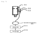
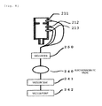
- Fig. 7 is a diagram illustrating an example of a mechanism for performing operations of suctioning the vacuum nozzles 211 to 213, and Fig. 8 is a diagram illustrating another example of the mechanism for performing operations of suctioning the vacuum nozzles 211 to 213.
- the vacuum nozzles 211 to 213 are connected to an electromagnetic valve 240, a vacuum tank 241, and a vacuum pump 242 via tubes. Vacuum suctioning of the vacuum tank 241 is performed by the vacuum pump 242. As the electromagnetic valve 240 opens, the vacuum nozzles 211 to 213 perform vacuum suctioning with respect to the inside of the washing tank 32.
- a difference between the example illustrated in Fig. 7 and the example illustrated in Fig. 8 is that a vacuum bin 250 is arranged between the electromagnetic valve 240 and the vacuum nozzles 211 to 213, in Fig. 8 . Both the examples in Figs. 7 and 8 can be applied with the present invention.
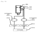
- Fig. 9 is a diagram illustrating an example of a mechanism for performing operations of discharging washing water through the washing nozzles 201 to 203
- Fig. 10 is a diagram illustrating another example of the mechanism for performing operations of discharging washing water through the washing nozzles 201 to 203.
- the washing nozzle 201 is connected to an electromagnetic valve 262, a low pressure pump 264, and a system water tank 265 via a tube.
- washing nozzles 202 and 203 are connected to an electromagnetic valve 261, a high pressure pump 263, and the system water tank 265 via tubes.
- discharge pressure of washing water from the washing nozzles 202 and 203 is set to high pressure, and discharge pressure of washing water from the washing nozzle 201 is set to low pressure.
- washing nozzles 201 and 203 are connected to the electromagnetic valve 262, the low pressure pump 264, and the system water tank 265 via tubes.
- washing nozzle 202 is connected to the electromagnetic valve 261, a high pressure pump 263, and the system water tank 265 via a tube.
- discharge pressure of washing water from the washing nozzles 201 and 203 is set to low pressure, and discharge pressure of washing water from the washing nozzle 202 is set to high pressure.
- the electromagnetic valves 240, 261, and 262, the vacuum pump 242, the high pressure pump 263, and the low pressure pump 264 are not shown in Fig. 1 but are included in the automatic analysis device as configuration mechanisms. In addition, operations of the electromagnetic valves 240, 261, and 262, the vacuum pump 242, a high pressure pump 263, and a low pressure pump 264 are controlled by the controller 21.
- Fig. 2B is a perspective cross-sectional view of the washing tank 32 according to another exemplary embodiment of the present invention.
- the electromagnetic valve 302 is included below the waste liquid portion 221.
- Fig. 3B is a top view of the washing tank 32, and the cross section taken along line B-B in Fig. 3B is the cross section illustrated in Fig. 2B .
- the washing tank 32 is formed with the structure having the shape illustrated in Fig. 2B and another structure having a shape symmetrical to the illustrated structure.
- the washing tank 33 is also configured to be equivalent to the washing tank 32.
- the reagent probe 7a in order to wash the reagent probe 7a, the reagent probe 7a is lowered into the washing tank 32. Then, the reagent probe 7a passes through the opening portion 303 formed on the top surface of the washing tank 32, and the throttle portion 301 forming a circular opening, thereby being inserted into the washing tank 32.
- the circular opening is the opening (portion) through which the reagent probe 7a is inserted, and the opening (portion) is formed in the throttle portion 301.
- the opening (portion) is not necessarily circular.
- the channel throttle portion 304 is formed in the opening portion 303.
- the throttle portion 301 includes the opening portion 303 and forms the channel through which washing water discharged from the washing nozzle 201 (the washing mechanism) flows in the horizontal direction.
- the washing nozzle 201 discharges washing water which flows on the top surface of the throttle portion 301.
- the channel width of the channel on the downstream side from the inlet port of the channel throttle portion 304 included in the throttle portion 301 is smaller than the channel width on the upstream side therefrom. It is acceptable when the channel width of the channel on the downstream side from the opening (portion) through which the reagent probe 7a is inserted is smaller than the channel width on the upstream side.
- the reagent probe 7a As washing water is supplied from the washing nozzle 201, and the washing water comes into contact with the reagent probe 7a, the reagent probe 7a is washed. Meanwhile, the electromagnetic valve 302 is in the open state. Then, after the reagent probe 7a is washed, the electromagnetic valve 302 below the waste liquid portion 221 is in the closed state, and the vacuum nozzles 212, 213, and 214 (a drying mechanism) connected to the washing portion 205 of the washing tank 32 start vacuum suctioning. While performing vacuum suctioning, the reagent probe 7a is lifted. The vacuum nozzles 212, 213, and 214 (the drying mechanism) performing vacuum suctioning of washing water are arranged below the throttle portion 301. In addition, the washing nozzle 201 (the washing mechanism) performs perifusion washing with washing water supplied from the washing nozzle with respect to a liquid which has scattered and adhered to the throttle portion 301.
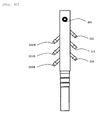
- Fig. 2B illustrates that the washing tank 32 is formed with the illustrated structure and another structure having the symmetrical shape. Another example different therefrom is illustrated as Fig. 3C.
- Fig. 3C is a side view of the washing tank seen from the washing nozzle 201 side.
- Fig. 2B different from that of Fig. 2A , there is no washing nozzle arranged below the throttle portion 301, and there is no suctioning nozzle 211 arranged above the throttle portion 301.
- the suctioning nozzles arranged on the side surface may be arranged alternately on the right and left as shown in Fig. 3C . Even though the suctioning nozzles are arranged in a bilateral symmetry manner, there is no change in the flow velocity at the throttle portion 301 due to vacuum suctioning. However, if the inner diameter of the washing portion 205 illustrated in Fig. 2A or 2B is decreased, washing water adhered to the reagent probe 7a can be directly suctioned through the vacuum nozzles on the side surface.
- suctioning nozzles are arranged alternately on the right and left as shown in Fig. 3C , washing water can be directly suctioned through the suctioning nozzles, thereby improving an effect of removing washing water. Therefore, it is desirable to include a plurality of suctioning nozzles 212, 213, and 214 (first suctioning nozzles) which are arranged in a perpendicular direction, and a plurality of suctioning nozzles 212B, 213B, and 214B (second suctioning nozzles) which are arranged in the perpendicular direction and are arranged at positions so as to interpose the reagent probe 7a between the suctioning nozzles (the first suctioning nozzles) and the suctioning nozzles (the second suctioning nozzles) in a state where the probe is inserted into the opening portion. It is desirable that the nozzles are arranged alternately in the perpendicular direction.
- Fig. 3C illustrates that there are provided six suctioning nozzles. However, if the suctioning effect is enhanced by widening the inner diameter of the vacuum nozzle, washing water can be removed even though there is provided only one suctioning nozzle. It is possible to achieve the effect by arranging six or more washing nozzles.
- a washing effect of the reagent probe 7a can be enhanced by increasing the flow velocity of a washing liquid discharged from the washing nozzle 201.
- a high pressure pump 263 illustrated in Figs. 9 and 10 may be connected to the washing nozzle 201, or a low pressure pump 264 may be connected to the washing nozzle 201.
- a variable throttle (not illustrated) is attached to a position between the electromagnetic valve 262 and the washing nozzle 201 and the flow velocity against the reagent probe 7a is increased when in use.
- vacuum suctioning pressure can be increased by increasing the number of the vacuum nozzles or increasing the inner diameter of the vacuum nozzle. Even though remaining washing water discharged from the washing nozzle 201 is accumulated on the top surface of the throttle portion, the washing water accumulated in the upper portion of the throttle portion 301 can be introduced to the throttle portion. When the reagent probe 7a is lifted, there is no washing water in the periphery of the throttle portion 301. Therefore, no washing water adheres to the reagent probe 7a.
- washing water accumulated in the upper portion of the throttle portion 301 is not contaminated washing water.
- the reason is as follows.
- the reagent and the like adhered onto the side surface of the reagent probe 7a flows into the overflow portion 222 during the operation of lowering the reagent probe 7a.
- washing water in the washing nozzle 201 is in a discharged state. Therefore, washing water is not contaminated.
- the reagent probe 7a is not contaminated.
- the washing nozzle 201 starts discharging of washing water.
- the reagent probe 7a starts being lowered toward the washing tank 32 so as to be inserted into the washing tank 32.
- washing water is discharged from the reagent probe 7a, thereby starting internal washing for washing the inside of the reagent probe 7a.
- the internal washing and external washing of the probe 7a are performed simultaneously.
- the opening portion is covered with washing water.
- washing water is discharged from the reagent probe 7a.
- the controller causes the washing nozzle 201 to discharge washing water therethrough in a state where the opening portion for insertion of the probe is covered with washing water, and the probe is lowered toward the opening portion. After the distal end of the probe passes through the opening portion, in a state where the opening portion is covered with the washing water while the probe is lowered, washing water is discharged from the inside of the probe.
- washing water is discharged from the inside of the probe.
- washing water discharged from the washing nozzle 201 plays a role as a lid with respect to the throttle portion 301, while the distal end of the reagent probe 7a is positioned lower than the throttle portion 301, washing water for washing the inside of the reagent probe 7a does not scatter from the throttle portion 301.
- water for internal washing can be discharged in an early stage, and thus, it is possible to reduce washing time.
- the electromagnetic valve 302 is in the closed state, and at a time i' , the vacuum nozzles 212, 213, and 214 start suctioning of the inside of the washing tank 32. Then, at a time j', an operation of lifting the reagent probe 7a starts. Subsequently, at a time k', an operation of washing the inside of the reagent probe 7a stops. At a time l', an operation of lifting the reagent probe 7a stops, and the vacuum nozzles 212, 213, and 214 stops suctioning of the inside of the washing tank 32. Then, at a time m', the electromagnetic valve 302 is in the open state.
- the controller stops the operation of lowering the reagent probe 7a, and then, the controller stops the operation of discharging a washing liquid through the washing nozzle 201 (the washing mechanism), thereby lifting the probe while performing a vacuum suctioning operation through the vacuum nozzles 212, 213, and 214 (the drying mechanisms) .
- the controller stops the operation of lowering the reagent probe 7a, and then, the controller stops the operation of discharging a washing liquid through the washing nozzle 201 (the washing mechanism), thereby lifting the probe while performing a vacuum suctioning operation through the vacuum nozzles 212, 213, and 214 (the drying mechanisms) .
- the controller stops the operation of lowering the reagent probe 7a, and then, the controller stops the operation of discharging a washing liquid through the washing nozzle 201 (the washing mechanism), thereby lifting the probe while performing a vacuum suctioning operation through the vacuum nozzles 212, 213, and 214 (the drying mechanisms) .
- the controller stops washing water discharged from the inside of the probe after the probe 7a is lifted and before the distal end of the probe 7a passes through the opening portion. Accordingly, water for internal washing can be prevented from scattering above the throttle portion 301.
- the controller causes the probe 7a to be lifted after starting a vacuum suctioning operation through the vacuum nozzles 212, 213, and 214 (the drying mechanisms) and after a predetermined period of time (a period of time between the time i' and the time j')has elapsed.
- a predetermined period of time a period of time between the time i' and the time j'
- the controller causes the probe 7a to be lifted after starting a vacuum suctioning operation through the vacuum nozzles 212, 213, and 214 (the drying mechanisms) and after a predetermined period of time (a period of time between the time i' and the time j')has elapsed.
- washing water which is discharged from the washing nozzle 201 and plays the role as a lid is suctioned below the throttle portion 301, and thus, the throttle portion 301 can be dried within the aforementioned predetermined period of time. After being dried, the outside of the probe can be dried more effectively by lifting the probe 7a.
- the vacuum nozzles 212, 213, and 214 also plays a role for promptly drying the throttle portion 301 in addition to the role for drying the outside of the probe.
- FIG. 6B Another operation illustrated in Fig. 6B is also executed by a command from the controller 21 in accordance with a program stored in the controller 21.
- the throttle portion 301 forms the channel through which washing water discharged from the washing nozzle 201 flows in the horizontal direction.
- the channel width of the channel on the downstream side from the opening portion is smaller than the channel width on the upstream side therefrom. Accordingly, washing water is likely to be accumulated in the opening portion, and thus, the opening portion can be effectively covered with washing water.
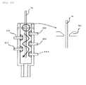
- Fig. 11 is a diagram illustrating a modification example of the washing tank 32.
- On the right side in Fig. 11 an enlarged portion of the throttle portion 301 is illustrated.
- the shape of the opening formed by the throttle portion 301 is caused to be a mortar shape, washing water discharged from the washing nozzle 201 can be accumulated in a mortar-shaped place.
- the mortar shape denotes a shape of which the opening diameter of the opening portion formed by the throttle portion decreases from the upper portion toward the lower portion.
- washing water discharged from the washing nozzle 201 abuts against the mortar-shaped throttle portion 301, thereby being in a turbulent flow, and the channel is throttled at the channel throttle portion 304, thereby being in a more turbulent flow.
- washing water adhered to the reagent probe 7a can be removed by lowering a range of the reagent probe 7a wetted by washing water from the washing nozzle 201 again compared to the throttle portion 301 after the reagent probe 7a is washed, or performing vacuum suctioning simultaneously with lowering thereof.
- washing water in the vicinity of the throttle portion 301 can be removed.
- washing water adhered to the reagent probe 7a can be removed by executing vacuum suctioning after the reagent probe 7a is washed, removing washing water within the range of the reagent probe 7a which is wetted due to washing water in the washing nozzle 201, and performing vacuum suctioning after lowering the range washed through the washing nozzle 201 of the reagent probe 7a again compared to the throttle portion 301.
- a washing nozzle 204 can be added.
- washing nozzles 202, 203, and 204, and the vacuum nozzles 212 and 213 are arranged so as to be projections protruding into the washing tank 32, washing water discharged from the washing nozzle 202 which is at a position above the washing tank 32 is in a turbulent flow in which distribution of the flow velocity is generated by being centered around the reagent probe 7a inserted into the washing tank 32, thereby dripping down. Therefore, without providing projections, a washing effect can be improved compared to a case where washing water is dripped or spouted from the upper portion toward the reagent probe 7a.
- the washing water is removed by performing vacuum suctioning through the vacuum nozzles 211 to 213 after washing water stops being discharged from the washing nozzles 202 to 204, thereby being out of the question.
- the positions of the washing nozzles 202 to 204 and the vacuum nozzles 211 to 213 are arranged on the right and left.
- an equivalent washing effect of the reagent probe 7a can be acquired even though the washing nozzles 202 to 204 and the vacuum nozzles 211 to 213 are arranged alternately, or the washing nozzles and the vacuum nozzles are vertically combined. Accordingly, there is no restriction on the arrangement between the washing nozzles and the vacuum nozzles.
- the distance between the vacuum nozzles 211 to 213 and the reagent probe 7a is configured to be 1 mm or less when the reagent probe 7a is inserted into the washing tank 32, washing water adhered onto the side surface of the reagent probe 7a can be directly suctioned. Accordingly, if vacuum suctioning is performed at all times while the reagent probe 7a is lifted, washing water adhered to the reagent probe 7a is directly suctioned. Moreover, a blowing effect can be acquired by the throttle portion 301. An adhesion removal effect of washing water in accordance with the above-described configuration is unconditional, and thus, it is possible to minimize adhesion of washing water.
- washing water is supplied from the washing nozzle 201 to the throttle portion 301 of the washing tank 32 so as to wash the throttle portion 301, and droplets adhered to the throttle portion 301 and the reagent probe 7a which have been washed are suctioned through the suctioning nozzle 211. Therefore, it is possible to realize the automatic analysis device including a washing device in which processes of the probe from washing to drying are carried out in the same washing tank, and adhesion of a liquid with respect to the washed probe can be avoided when being drawn out from the opening portion of the washing tank 32.
- the reagent probe 7a is inserted into the washing tank 32. While performing the lowering operation, a washing operation of the inside of the probe 7a is performed. Simultaneously, washing of washing the outside of the probe 7a is executed through the washing nozzles 201 to 203. Even when the reagent probe 7a is lifted, a drying operation is performed through the vacuum nozzles 211 and 212. Thus, washing and drying operations of the reagent probe 7a can be sped up and can be performed in a short period of time.
- the washing nozzle 203 and the vacuum nozzles 212 and 213 are attached to the side surface of the washing tank 32 so as to be angulated in place of being perpendicular thereto.
- the necessary performance can be acquired whether the nozzles are positioned to be angulated or to be horizontally arranged.
- the number of nozzles can be arranged alternately and diagonally, or the speed of the air flow intruding from the throttle portion 301 can vary by increasing the number of the vacuum suctioning nozzles.
- the attachment angle there is no limitation on the attachment angle.
- the number of the washing nozzles arranged in the lower portion of the throttle portion 301 is set to two in the example illustrated in Fig. 2A , and the number is set to three in the example illustrated in Fig. 11 .
- the number of the washing nozzles in the arrangement varies such as one washing nozzle from a high pressure pump, or two or three washing nozzles from a low pressure pump, it is possible to acquire a required washing effect.
- the inside of the washing tank 32 in which the washing nozzles and the vacuum nozzles in the lower portion of the throttle portion 301 are arranged may have a cylindrical shape or a square shape to be used.
- the washing tank 32 of the present invention has been described related to the reagent probe 7a.
- the sample probe 11a is thrust deep inside a specimen of the sample container 15 and a sample is suctioned from the bottom of the sample container 15.
- the washing range of the sample probe 11a covers a wide range. Therefore, the washing tank of the present invention is not limited only to washing of the reagent probe. It is effective when used for washing a probe such as a sample probe which requires washing over a wide range.
- the suctioning nozzle 211 and the washing nozzle 201 configure a first washing and drying mechanism.
- the vacuum nozzles (the suctioning nozzles) 212 and 213 and the washing nozzles 202 and 203 configure a second washing and drying mechanism.
- washing nozzle; 205 ... washing portion; 211, 212, 213, 214 ... suctioning nozzle (vacuum nozzle) ; 221 ... waste liquid portion; 222 ... overflow portion; 240, 261, 262 ... electromagnetic valve; 241 ... vacuum tank; 242 ... vacuum pump; 263 ... high pressure pump; 264 ... low pressure pump; 265 ... system water tank; 301 ... throttle portion; 302 ... electromagnetic valve; 303 ... opening portion; 304 ... channel throttle portion
Landscapes
- Physics & Mathematics (AREA)
- Health & Medical Sciences (AREA)
- Life Sciences & Earth Sciences (AREA)
- Chemical & Material Sciences (AREA)
- Analytical Chemistry (AREA)
- Biochemistry (AREA)
- General Health & Medical Sciences (AREA)
- General Physics & Mathematics (AREA)
- Immunology (AREA)
- Pathology (AREA)
- Automatic Analysis And Handling Materials Therefor (AREA)
Abstract
Description
- The present invention relates to an automatic analysis device which analyzes a reagent and a liquid sample such as blood or urine.
- For example, an automatic analysis device such as an automatic biochemical analyzer and an automatic immunoassay analyzer includes a washing tank for washing a probe with washing water after suctioning and discharging a reagent or a target specimen sample.
- Generally, a level of contamination of the probe during suctioning of the reagent or the target specimen sample performed by using the probe is in a volume range of approximately 5 mm in which the probe is thrust into the reagent or the sample after the probe detects the liquid surface. Therefore, the range becomes a washing range of the probe. However, for example, in order to prevent evaporation of the reagent, when suctioning the reagent through the probe from a notched reagent bottle attached with a cap, the probe needs to be washed over a wide range corresponding to the range from the cap of the reagent to the bottom of the reagent bottle.
- However, widening of the washing range of the probe results in a disadvantage described below. First, as the washing range is widened, a washing time needs to be sufficiently provided. In addition, after the probe is washed, a large quantity of washing water adhered onto a side surface of the probe remains. If a succeeding reagent is suctioned through the probe in such a state, it is assumed that the washing water adhered onto the side surface of the probe is mixed in the reagent bottle, thereby leading to dilution of the reagent caused by washing water.
- Even in a case where the probe is thrust deep inside the target specimen sample, as described above, an equivalent disadvantage is caused due to the wide washing range of the probe.
- Therefore, when the washing range of the probe is wide (example: a washing range of 80 mm), as a method of removing washing water adhered onto the side surface of the probe after the probe is washed, there is a known method of removing washing water adhered onto the side surface of the probe by moving the probe to a position of a vacuum suctioning tube after being washed at a probe washing position, lowering the probe into the vacuum suctioning tube, and evacuating the inside of the vacuum suctioning tube (
PTL 1 and PTL 2). -
- PTL 1:
JP-A-2002-340913 - PTL 2:
JP-A-2006-257491 - According to the technologies disclosed
PTL 1 andPTL 2, since a washed probe moves to the top surface of a vacuum suctioning tube, there is no contamination in the vicinity of a vacuum suctioning port caused by a reagent adhered onto the probe, a target specimen sample, and washing water scattered during washing of the probe. - Here, there is a demand for a quicker operation in an automatic analysis device and minimization of an installation space for a washing tank. In this case, it is considered to execute processes of the probe from washing to drying in the same washing tank, to speed up a washing operation, and to minimize the installation space.
- In this case, considering an improvement of efficiency in removing washing water adhered onto the probe during vacuum suctioning, it is considered to narrow an opening portion of the washing tank.
- However, when the hole diameter of the opening portion of the washing tank is decreased, there is a significant possibility that the reagent or the target specimen sample adhered onto the probe when the probe is lowered into the washing tank before being washed may scatter or adhere onto the vicinity of the opening portion of the washing tank. As the probe is inserted into the washing tank, there is a high risk in that the vicinity of the opening portion of the washing tank is contaminated by the reagent or the target specimen sample scattered or adhered, and when the probe is lifted in order to dry the probe after being washed in the washing tank, the probe comes into contact with a liquid scattered or adhered onto the vicinity of the opening portion of the washing tank, thereby causing contamination during suctioning of a succeeding liquid.
- An object of the present invention is to realize an automatic analysis device in which a washing effect of a probe is improved by being washed in a short period of time and washing water and the like which may be mixed in during suctioning of a succeeding liquid can be decreased.
- The following is a configuration of the present invention for achieving the aforementioned objects.
- According to a representative aspect of the invention, there is provided an automatic analysis device including: a probe that suctions a reagent or a sample and discharges the reagent or the sample into a reaction container; a dispensing mechanism that moves the probe vertically and horizontally; a suctioning and discharging mechanism that causes the probe to suction the reagent or the sample and discharges the reagent or the sample into the reaction container; a photometer that analyzes the sample in the reaction container; a throttle portion that forms an opening portion into which the probe is inserted; a washing mechanism that discharges washing water which flows on a top surface of the throttle portion;
a drying mechanism that is arranged below the throttle portion and performs vacuum suctioning of washing water; and
a controller that controls operations of the dispensing mechanism, the suctioning and discharging mechanism, the washing mechanism, and the drying mechanism. - In addition, in an automatic analysis device, a washing tank for washing a probe that suctions a reagent or a sample and discharges the reagent and the sample to a reaction container includes a throttle portion forming an opening portion into which the probe is inserted, a first washing and drying mechanism being arranged near the throttle portion and performing discharging and vacuum suctioning of washing water, a washing portion being formed below the throttle portion, and a second washing and drying mechanism being connected to the washing portion and performing discharging and vacuum suctioning of washing water. Processes of the probe from washing to drying are performed in the same washing tank.
- According to the present invention, it is possible to realize an automatic analysis device in which a washing effect of a probe is improved by being washed in a short period of time and washing water and the like which may be mixed in during suctioning of a succeeding liquid can be decreased.
-
- [
Fig. 1] Fig. 1 is a diagram of a schematic configuration of an automatic analysis device to which the present invention is applied. - [
Fig. 2A] Fig. 2A is a perspective cross-sectional view of a washing tank according to an exemplary embodiment of the present invention. - [
Fig. 2B] Fig. 2B is a perspective cross-sectional view of the washing tank according to another exemplary embodiment of the present invention. - [
Fig. 3A] Fig. 3A is a top view of the washing tank. - [
Fig. 3B] Fig. 3B is another top view of the washing tank. - [
Fig. 3C] Fig. 3C is a side view of the washing tank. - [
Fig. 4] Fig. 4 is an explanatory diagram of a configuration of the washing tank. - [
Fig. 5] Fig. 5 is another explanatory diagram of the configuration of the washing tank. - [
Fig. 6A] Fig. 6A is a time chart of an operation of washing a reagent probe. - [
Fig. 6B] Fig. 6B is a time chart of another operation of washing the reagent probe. - [
Fig. 7] Fig. 7 is a diagram illustrating an example of a mechanism for performing operations of suctioning vacuum nozzles. - [
Fig. 8] Fig. 8 is a diagram illustrating another example of the mechanism for performing operations of suctioning the vacuum nozzles. - [
Fig. 9] Fig. 9 is a diagram illustrating an example of a mechanism for performing operations of discharging washing water through washing nozzles. - [
Fig. 10] Fig. 10 is a diagram illustrating another example of the mechanism for performing operations of discharging washing water through the washing nozzle. - [
Fig. 11] Fig. 11 is a diagram illustrating a modification example of the washing tank. - Hereinafter, an exemplary embodiment of the present invention will be described with reference to the drawings.
-
Fig. 1 is a diagram of a schematic configuration of an automatic analysis device to which the present invention is applied. - In
Fig. 1 ,reaction containers 2 are arranged on the circumference of areaction disk 1. A plurality ofreagent bottles 10 can be arranged on the circumference of a reagent disk 9. In addition,detergent bottles 10a can be arranged in the reagent disk 9. Asample transportation mechanism 17 for moving arack 16 mounted withsample containers 15 is installed near thereaction disk 1. - Reagent dispensing mechanisms 7 and 8 which can rotate and vertically move are installed between the
reaction disk 1 and the reagent disk 9, and each of the reagent dispensing mechanisms 7 and 8 includes areagent probe 7a. Thereagent probe 7a moves vertically and horizontally by the reagent dispensing mechanism 7 or 8. Reagent syringes 18 (suctioning and discharging mechanisms) are respectively connected to the reagent probes 7a. The reagent syringes 18 suctions and discharges a reagent through the reagent probes 7a. In addition, the reagent syringes 18 discharges washing water into thereagent probe 7a and suctions washing water or detergent from thedetergent bottle 10a, thereby washing the inside of thereagent probe 7a. - In addition, a
sample dispensing mechanism 11 which can rotate and vertically move is installed between thereaction disk 1 and thesample transportation mechanism 17, and thesample dispensing mechanism 11 includes asample probe 11a. Each ofsample syringes 19 are connected to thesample probe 11a. Thesample probe 11a moves horizontally in an arc while being centered around the rotary axis. Thesample probe 11a moves vertically so as to dispense sample from a sample container to thereaction container 2. - In the periphery of the
reaction disk 1, awashing mechanism 3, aspectrophotometer 4 for analyzing a sample in thereaction container 2, stirring mechanisms 5 and 6, the reagent disk 9, and thesample transportation mechanism 17 are arranged. A washing pump 20 is connected to thewashing mechanism 3.Washing tanks sample dispensing mechanism 11, the stirring mechanisms 5 and 6. The washing tank 13 is a washing tank for thesample probe 11a, and thewashing tanks 30 and 31 are washing tanks for the stirring mechanisms 5 and 6. Then, thewashing tanks reagent probe 7a and the reagent dispensing probe of the reagent dispensing mechanism 8. - The
sample container 15 contains an inspection sample such as blood and is mounted on therack 16, thereby being carried by thesample transportation mechanism 17. In addition, each of the mechanisms is connected to a controller 21, and operational control thereof is performed by the controller 21. - A cap is attached to a position of a reagent probe suctioning port of the
reagent bottle 10 in order to seal the inside thereof. Generally, the cap is detached when thereagent bottle 10 is set in the automatic analysis device, and then, thereagent bottle 10 is installed in the device. However, recently, there is provided a method in which a notch-like hole is bored in the cap and thereagent probe 7a is inserted into a notch portion so as to suction a reagent. Since a slight notch becomes an opening portion of the cap for thereagent bottle 10, contact of the reagent with respect to the air outside is minimized, thereby improving deterioration of the reagent. - However, since a washing range of the
reagent probe 7a becomes the overall range of thereagent probe 7a which is inserted through the cap of thereagent bottle 10 in order to suction a reagent, it is necessary to perform washing over a wide range compared to a case where thereagent bottle 10 includes no cap. -
Fig. 2A is a perspective cross-sectional view of thewashing tank 32 according to an exemplary embodiment of the present invention. Thewashing tank 32 is configured to include anelectromagnetic valve 302 below awaste liquid portion 221. In addition,Fig. 3A is a top view of thewashing tank 32. The cross section taken along line A-A inFig. 3A is the cross section illustrated inFig. 2A . Thewashing tank 32 is formed with the structure having the shape illustrated inFig. 2A and another structure having a shape symmetrical to the illustrated structure. However, asuctioning nozzle 211 described-below is formed in only one structure therebetween. Thewashing tank 33 is also configured to be equivalent to thewashing tank 32. - In
Figs. 2A and3A , in order to wash thereagent probe 7a, thereagent probe 7a is lowered into thewashing tank 32. Then, thereagent probe 7a passes through anopening portion 303 formed on the top surface of thewashing tank 32, and athrottle portion 301 forming a circular opening, thereby being inserted into thewashing tank 32. The circular opening is an opening (portion) through which thereagent probe 7a is inserted, and the opening (portion) is formed in thethrottle portion 301. The opening (portion) is not necessarily circular. -
Washing nozzles washing tank 32 so as to supply washing water to the inside of thewashing tank 32. Achannel throttle portion 304 is formed in theopening portion 303. Thethrottle portion 301 includes theopening portion 303 and forms a channel through which washing water discharged from awashing nozzle 201 flows in a horizontal direction. Thewashing nozzle 201 discharges washing water which flows on the top surface of thethrottle portion 301. The channel width of the channel on a downstream side from an inlet port of thechannel throttle portion 304 included in thethrottle portion 301 is smaller than the channel width on an upstream side therefrom. It is acceptable that the channel width of the channel on the downstream side from the opening (portion) through which thereagent probe 7a is inserted is smaller than the channel width on the upstream side. - A
washing portion 205 for washing the reagent probe is formed below from theopening portion 303. The washing nozzles 202 and 203 are connected to thewashing portion 205. - Washing water is supplied from the
washing nozzles washing portion 205 inside thewashing tank 32. Thereagent probe 7a is washed by applying washing water to thereagent probe 7a. Meanwhile, theelectromagnetic valve 302 is in an open state. Then, after being washed of thereagent probe 7a, theelectromagnetic valve 302 below thewaste liquid portion 221 is in a closed state. Then,vacuum nozzles washing portion 205 of thewashing tank 32 start vacuum suctioning, and thereagent probe 7a is lifted while performing vacuum suctioning. - The suctioning velocity of the air intruding into the
washing tank 32 during vacuum suctioning performed through thevacuum nozzles throttle portion 301. Washing water adhered to thereagent probe 7a is blown away through thethrottle portion 301, and then, washing water can be removed. Here, if the diameter of the opening formed by thethrottle portion 301 is excessively significant compared to the outer diameter of thereagent probe 7a, the air intruding into thewashing tank 32 diminishes in velocity. Accordingly, an effect of blowing washing water adhered onto the side surface of thereagent probe 7a decreases, resulting in dilution caused by remaining washing water when performing suctioning of a succeeding liquid. - As a countermeasure therefor, as illustrated in
Fig. 4 , the size of the opening formed by thethrottle 301 is decreased so that the intruding velocity of the air through thethrottle portion 301 during vacuum suctioning can be increased. - When clearance between the outer diameter of the
reagent probe 7a and the diameter of the hole (the diameter of the opening) formed by thethrottle portion 301 is caused to range within 0.2 mmm to 1.0 mm, a drying effect of thereagent probe 7a increases. As an example, when the outer diameter of thereagent probe 7a is 2 mm, it is favorable that an optimum hole diameter of thethrottle portion 301 ranges approximately within 2.4 mm to 4.0 mm. - However, as illustrated in
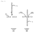
Fig. 5(A) , by narrowing thethrottle portion 301, there is no liquid adhered to thethrottle portion 301 before thereagent probe 7a passes through thethrottle portion 301, but as illustrated inFig. 5(B) , there is a case where a liquid adhered to thereagent probe 7a adheres to thethrottle portion 301 and the vicinity thereof after thereagent probe 7a passes through thethrottle portion 301. - In a state where a liquid adheres to the
throttle portion 301, when lifting thereagent probe 7a in order to remove washing water after being washed, the liquid adheres onto the side surface of thereagent probe 7a, and the liquid adhered to theprobe 7a mixes in during suctioning of a succeeding liquid, thereby causing contamination. - As a countermeasure therefor, as illustrated in
Fig. 2A , thewashing nozzle 201 which communicates with an upper portion of thethrottle portion 301 is connected to thewashing tank 32, and then, a liquid which has scattered and adhered to thethrottle portion 301 is subjected to perifusion washing with washing water supplied from thewashing nozzle 201. Thewashing tank 32 is connected to thevacuum nozzles washing tank 32, and thesuctioning nozzle 211 which is connected to the vicinity of thethrottle portion 301 on an outlet port side. After thethrottle portion 301 is washed by using thewashing nozzle 201, if thereagent probe 7a is lifted while performing suctioning through thevacuum nozzles suctioning nozzle 211, thereagent probe 7a can be drawn out from thewashing tank 301 allowing no liquid to adhere to thereagent probe 7a. - As a specific method of using the
washing nozzle 201, as described above, after washing thereagent probe 7a through thewashing nozzles throttle portion 301 is subjected to perifusion. - Otherwise, as illustrated in the time chart of
Fig. 6A , washing water is discharged from thewashing nozzle 201 before washing thereagent probe 7a. Next, while washing water is discharged from thewashing nozzles washing nozzle 201 is applied to thereagent probe 7a, and thereagent probe 7a is lowered. Most liquids adhered to thereagent probe 7a are removed by the washing water discharged from thewashing nozzle 201. In order to achieve a greater washing effect, washing is performed through thewashing nozzles - Here, with reference to the time chart of an operation of washing the
reagent probe 7a illustrated inFig. 6A , descriptions will be given regarding operations of thereagent probe 7a, thewashing nozzles 201 to 203, theelectromagnetic valve 302, thevacuum nozzles - In
Fig. 6A , at a time a, thewashing nozzle 201 starts discharging of washing water. Subsequently, at a time b, thewashing nozzles reagent probe 7a starts being lowered toward thewashing tank 32 so as to be inserted into thewashing tank 32. Then, at a time d, washing water is discharged from thereagent probe 7a, thereby starting internal washing for washing the inside of thereagent probe 7a. The internal washing and external washing of theprobe 7a are performed simultaneously. - Next, at a time e, an operation of lowering the
reagent probe 7a stops. Thereafter, at a time f, thewashing nozzles washing nozzle 201 stops discharging of washing water. - Next, at a time h, the
electromagnetic valve 302 is in the closed state, and at a time i, thevacuum nozzles washing tank 32. Then, at a time j, an operation of lifting thereagent probe 7a starts. Subsequently, at a time k, an operation of washing the inside of thereagent probe 7a stops. At a time l, the operation of lifting thereagent probe 7a stops, and thevacuum nozzles washing tank 32. Then, at a time m, theelectromagnetic valve 302 is in the open state. - The above-described operation is executed by a command from the controller 21 in accordance with a program stored in the controller 21.
- It is possible to adopt a method in which washing water discharged from the
washing nozzles reagent probe 7a at the high-pressure flow velocity. Regarding washing water discharged from thewashing nozzle 201, since the diameter of thethrottle portion 301 is minimized, most of the washing water discharged from thewashing nozzle 201 passes through thethrottle portion 301 so as to flow down into anoverflow portion 222 without dripping from thethrottle portion 301. Since washing water discharged from thewashing nozzle 201 flows so as to form a lid without dripping from thethrottle portion 301, there is no need to be concerned about scattering of washing water discharged from thewashing nozzles throttle portion 301 to the upper portion. - In addition, since washing water discharged from the
washing nozzle 201 plays a role as a lid with respect to thethrottle portion 301, while the distal end of thereagent probe 7a is positioned lower than thethrottle portion 301, washing water for washing the inside of thereagent probe 7a does not scatter from thethrottle portion 301. In addition, while thereagent probe 7a is lifted, the inside of thewashing tank 32 is subjected to vacuum suctioning by thevacuum nozzles washing tank 32 with respect to thethrottle portion 301. Accordingly, the inside of thereagent probe 7a can be washed for a long period of time from the lowering of theprobe 7a to the lifting thereof, and thus, thereagent probe 7a can be effectively washed. - Here, there is a slight time difference between a time at which the
washing nozzles vacuum nozzles sample probe 7a is lowered into thewashing tank 32 and stops thereat, a washing liquid discharged from the distal end of thesample probe 7a does not scatter from thethrottle portion 301. Naturally, a vacuum suctioning operation may be immediately performed after thewashing nozzle 201 stops the operation of discharging washing water so as to eliminate the time difference. - The aforementioned high-pressure washing water denotes hydraulic pressure in a range from five times to twenty times the normal hydraulic pressure of washing water. Even though high-pressure washing water is applied to the
reagent probe 7a, washing water discharged from thewashing nozzle 201 plays a role as a lid with respect to thethrottle portion 301, and thus, the high-pressure washing water does not scatter from thethrottle portion 301. If a washing effect is enhanced by washing thereagent probe 7a with high-pressure water, as a result, an effect of a reduction in washing time or an effect of removing a reagent adhered onto the side surface of theprobe 7a are improved, thereby leading to a reduction of carried over reagents. Thus, it is possible to achieve a quicker operation of the automatic analysis device which includes thereagent probe 7a. - In addition, as illustrated in
Fig. 3A , by forming thechannel throttle portion 304 in the channel through which washing water discharged from thewashing nozzle 201 reaches theoverflow 222, there is provided a structure in thethrottle portion 301 in which washing water discharged from thewashing nozzle 201 is accumulated. As washing water is accumulated therein, a stream of washing water increases in thickness, and thus, the washing range of theprobe 7a can be widened. Accordingly, it is possible to eliminate the risk of scattering of washing water from thethrottle portion 301 under circumstances of reduced washing time and washing with high-pressure water. - Here, descriptions will be given regarding operations of discharging washing water performed through the
washing nozzles 201 to 203, and mechanisms of operations of suctioning performed through thevacuum nozzles 211 to 213. -
Fig. 7 is a diagram illustrating an example of a mechanism for performing operations of suctioning thevacuum nozzles 211 to 213, andFig. 8 is a diagram illustrating another example of the mechanism for performing operations of suctioning thevacuum nozzles 211 to 213. - In
Fig. 7 , thevacuum nozzles 211 to 213 are connected to an electromagnetic valve 240, a vacuum tank 241, and avacuum pump 242 via tubes. Vacuum suctioning of the vacuum tank 241 is performed by thevacuum pump 242. As the electromagnetic valve 240 opens, thevacuum nozzles 211 to 213 perform vacuum suctioning with respect to the inside of thewashing tank 32. - A difference between the example illustrated in
Fig. 7 and the example illustrated inFig. 8 is that avacuum bin 250 is arranged between the electromagnetic valve 240 and thevacuum nozzles 211 to 213, inFig. 8 . Both the examples inFigs. 7 and8 can be applied with the present invention. -
Fig. 9 is a diagram illustrating an example of a mechanism for performing operations of discharging washing water through thewashing nozzles 201 to 203, andFig. 10 is a diagram illustrating another example of the mechanism for performing operations of discharging washing water through thewashing nozzles 201 to 203. - In
Fig. 9 , thewashing nozzle 201 is connected to anelectromagnetic valve 262, alow pressure pump 264, and asystem water tank 265 via a tube. - In addition, the
washing nozzles high pressure pump 263, and thesystem water tank 265 via tubes. - In the example illustrated in
Fig. 9 , discharge pressure of washing water from thewashing nozzles washing nozzle 201 is set to low pressure. - In addition, in
Fig. 10 , thewashing nozzles electromagnetic valve 262, thelow pressure pump 264, and thesystem water tank 265 via tubes. - In addition, the
washing nozzle 202 is connected to the electromagnetic valve 261, ahigh pressure pump 263, and thesystem water tank 265 via a tube. - In the example illustrated in
Fig. 10 , discharge pressure of washing water from thewashing nozzles washing nozzle 202 is set to high pressure. - The
electromagnetic valves 240, 261, and 262, thevacuum pump 242, thehigh pressure pump 263, and thelow pressure pump 264 are not shown inFig. 1 but are included in the automatic analysis device as configuration mechanisms. In addition, operations of theelectromagnetic valves 240, 261, and 262, thevacuum pump 242, ahigh pressure pump 263, and alow pressure pump 264 are controlled by the controller 21. -
Fig. 2B is a perspective cross-sectional view of thewashing tank 32 according to another exemplary embodiment of the present invention. In the structure thereof, theelectromagnetic valve 302 is included below thewaste liquid portion 221. In addition,Fig. 3B is a top view of thewashing tank 32, and the cross section taken along line B-B inFig. 3B is the cross section illustrated inFig. 2B . Thewashing tank 32 is formed with the structure having the shape illustrated inFig. 2B and another structure having a shape symmetrical to the illustrated structure. Thewashing tank 33 is also configured to be equivalent to thewashing tank 32. - In
Figs. 2B and3B , in order to wash thereagent probe 7a, thereagent probe 7a is lowered into thewashing tank 32. Then, thereagent probe 7a passes through theopening portion 303 formed on the top surface of thewashing tank 32, and thethrottle portion 301 forming a circular opening, thereby being inserted into thewashing tank 32. The circular opening is the opening (portion) through which thereagent probe 7a is inserted, and the opening (portion) is formed in thethrottle portion 301. The opening (portion) is not necessarily circular. - The
channel throttle portion 304 is formed in theopening portion 303. Thethrottle portion 301 includes theopening portion 303 and forms the channel through which washing water discharged from the washing nozzle 201 (the washing mechanism) flows in the horizontal direction. Thewashing nozzle 201 discharges washing water which flows on the top surface of thethrottle portion 301. The channel width of the channel on the downstream side from the inlet port of thechannel throttle portion 304 included in thethrottle portion 301 is smaller than the channel width on the upstream side therefrom. It is acceptable when the channel width of the channel on the downstream side from the opening (portion) through which thereagent probe 7a is inserted is smaller than the channel width on the upstream side. - As washing water is supplied from the
washing nozzle 201, and the washing water comes into contact with thereagent probe 7a, thereagent probe 7a is washed. Meanwhile, theelectromagnetic valve 302 is in the open state. Then, after thereagent probe 7a is washed, theelectromagnetic valve 302 below thewaste liquid portion 221 is in the closed state, and thevacuum nozzles washing portion 205 of thewashing tank 32 start vacuum suctioning. While performing vacuum suctioning, thereagent probe 7a is lifted. The vacuum nozzles 212, 213, and 214 (the drying mechanism) performing vacuum suctioning of washing water are arranged below thethrottle portion 301. In addition, the washing nozzle 201 (the washing mechanism) performs perifusion washing with washing water supplied from the washing nozzle with respect to a liquid which has scattered and adhered to thethrottle portion 301. -
Fig. 2B illustrates that thewashing tank 32 is formed with the illustrated structure and another structure having the symmetrical shape. Another example different therefrom is illustrated asFig. 3C. Fig. 3C is a side view of the washing tank seen from thewashing nozzle 201 side. - In the structure of
Fig. 2B , different from that ofFig. 2A , there is no washing nozzle arranged below thethrottle portion 301, and there is no suctioningnozzle 211 arranged above thethrottle portion 301. The suctioning nozzles arranged on the side surface may be arranged alternately on the right and left as shown inFig. 3C . Even though the suctioning nozzles are arranged in a bilateral symmetry manner, there is no change in the flow velocity at thethrottle portion 301 due to vacuum suctioning. However, if the inner diameter of thewashing portion 205 illustrated inFig. 2A or2B is decreased, washing water adhered to thereagent probe 7a can be directly suctioned through the vacuum nozzles on the side surface. Moreover, if the suctioning nozzles are arranged alternately on the right and left as shown inFig. 3C , washing water can be directly suctioned through the suctioning nozzles, thereby improving an effect of removing washing water. Therefore, it is desirable to include a plurality of suctioningnozzles nozzles 212B, 213B, and 214B (second suctioning nozzles) which are arranged in the perpendicular direction and are arranged at positions so as to interpose thereagent probe 7a between the suctioning nozzles (the first suctioning nozzles) and the suctioning nozzles (the second suctioning nozzles) in a state where the probe is inserted into the opening portion. It is desirable that the nozzles are arranged alternately in the perpendicular direction. -
Fig. 3C illustrates that there are provided six suctioning nozzles. However, if the suctioning effect is enhanced by widening the inner diameter of the vacuum nozzle, washing water can be removed even though there is provided only one suctioning nozzle. It is possible to achieve the effect by arranging six or more washing nozzles. - In addition, even though there is no washing nozzle arranged below the
throttle portion 301, a washing effect of thereagent probe 7a can be enhanced by increasing the flow velocity of a washing liquid discharged from thewashing nozzle 201. As means for increasing the flow velocity, ahigh pressure pump 263 illustrated inFigs. 9 and10 may be connected to thewashing nozzle 201, or alow pressure pump 264 may be connected to thewashing nozzle 201. When using a low pressure pump, it is desirable that a variable throttle (not illustrated) is attached to a position between theelectromagnetic valve 262 and thewashing nozzle 201 and the flow velocity against thereagent probe 7a is increased when in use. - In addition, even though there is no suctioning
nozzle 211 arranged above thethrottle portion 301, vacuum suctioning pressure can be increased by increasing the number of the vacuum nozzles or increasing the inner diameter of the vacuum nozzle. Even though remaining washing water discharged from thewashing nozzle 201 is accumulated on the top surface of the throttle portion, the washing water accumulated in the upper portion of thethrottle portion 301 can be introduced to the throttle portion. When thereagent probe 7a is lifted, there is no washing water in the periphery of thethrottle portion 301. Therefore, no washing water adheres to thereagent probe 7a. - In addition, washing water accumulated in the upper portion of the
throttle portion 301 is not contaminated washing water. The reason is as follows. The reagent and the like adhered onto the side surface of thereagent probe 7a flows into theoverflow portion 222 during the operation of lowering thereagent probe 7a. Even though thereagent probe 7a is lowered into the washing tank and stops thereat, washing water in thewashing nozzle 201 is in a discharged state. Therefore, washing water is not contaminated. As a result, even though washing water accumulated in the upper portion of thethrottle portion 301 is introduced to the inside of thethrottle portion 301, thereagent probe 7a is not contaminated. - With reference to the time chart of an operation of washing the
reagent probe 7a illustrated inFig. 6B , descriptions will be given regarding operations of thereagent probe 7a, thewashing nozzle 201, theelectromagnetic valve 302, and thevacuum nozzles - In
Fig. 6B , at a time a', thewashing nozzle 201 starts discharging of washing water. Next, at a time c', thereagent probe 7a starts being lowered toward thewashing tank 32 so as to be inserted into thewashing tank 32. Then, at a time d', washing water is discharged from thereagent probe 7a, thereby starting internal washing for washing the inside of thereagent probe 7a. The internal washing and external washing of theprobe 7a are performed simultaneously. At the timing at which thereagent probe 7a is inserted into the opening portion, the opening portion is covered with washing water. At the time d' which is a time after theprobe 7a passes through the opening portion, washing water is discharged from thereagent probe 7a. - In other words, the controller causes the
washing nozzle 201 to discharge washing water therethrough in a state where the opening portion for insertion of the probe is covered with washing water, and the probe is lowered toward the opening portion. After the distal end of the probe passes through the opening portion, in a state where the opening portion is covered with the washing water while the probe is lowered, washing water is discharged from the inside of the probe. In such a structure, similar toFigs. 2A ,3A , and6A , since washing water discharged from thewashing nozzle 201 plays a role as a lid with respect to thethrottle portion 301, while the distal end of thereagent probe 7a is positioned lower than thethrottle portion 301, washing water for washing the inside of thereagent probe 7a does not scatter from thethrottle portion 301. In addition, on account of the role as the lid, water for internal washing can be discharged in an early stage, and thus, it is possible to reduce washing time. - Next, at a time e', an operation of lowering the
reagent probe 7a stops. Subsequently, at a time g', discharging of washing water through thewashing nozzle 201 stops. - Next, at a time h', the
electromagnetic valve 302 is in the closed state, and at a time i' , thevacuum nozzles washing tank 32. Then, at a time j', an operation of lifting thereagent probe 7a starts. Subsequently, at a time k', an operation of washing the inside of thereagent probe 7a stops. At a time l', an operation of lifting thereagent probe 7a stops, and thevacuum nozzles washing tank 32. Then, at a time m', theelectromagnetic valve 302 is in the open state. - In other words, the controller stops the operation of lowering the
reagent probe 7a, and then, the controller stops the operation of discharging a washing liquid through the washing nozzle 201 (the washing mechanism), thereby lifting the probe while performing a vacuum suctioning operation through thevacuum nozzles reagent probe 7a is lifted, the probe can be drawn out while being dried, and thus, it is possible to reduce washing time. In addition, during vacuum suctioning, since the air is in a flow intruding into thewashing tank 32 from the outside via the opening portion of thethrottle portion 301, washing water adhered to the outer portion of the probe can be relegated to the distal end side of the probe. Therefore, it is possible to generate a suctioning force of the vacuum nozzle and a flow of the air enhancing a drying effect. Moreover, on account of the intruding flow of the air, water for internal washing of the probe can be prevented from scattering from thethrottle portion 301. Accordingly, the inside of thereagent probe 7a can be washed for a long period of time from the lowering of theprobe 7a to the lifting thereof, and thus, thereagent probe 7a can be effectively washed. - In addition, the controller stops washing water discharged from the inside of the probe after the
probe 7a is lifted and before the distal end of theprobe 7a passes through the opening portion. Accordingly, water for internal washing can be prevented from scattering above thethrottle portion 301. - In addition, the controller causes the
probe 7a to be lifted after starting a vacuum suctioning operation through thevacuum nozzles washing nozzle 201 and plays the role as a lid is suctioned below thethrottle portion 301, and thus, thethrottle portion 301 can be dried within the aforementioned predetermined period of time. After being dried, the outside of the probe can be dried more effectively by lifting theprobe 7a. As washing water stops being discharged through thewashing nozzle 201, washing water from thethrottle portion 301 flows downward due to gravity. However, when vacuum suctioning is not performed, it takes time for the opening portion to be dried due to the narrow clearance between the probe and the opening portion. Meanwhile, the aforementioned time can be reduced by performing the vacuum suctioning operation before drying thethrottle portion 301. In other words, thevacuum nozzles throttle portion 301 in addition to the role for drying the outside of the probe. - Another operation illustrated in
Fig. 6B is also executed by a command from the controller 21 in accordance with a program stored in the controller 21. - In
Fig. 3B , similar toFig. 3A , thethrottle portion 301 forms the channel through which washing water discharged from thewashing nozzle 201 flows in the horizontal direction. The channel width of the channel on the downstream side from the opening portion is smaller than the channel width on the upstream side therefrom. Accordingly, washing water is likely to be accumulated in the opening portion, and thus, the opening portion can be effectively covered with washing water. In other words, it is possible to promptly carry out the role as a lid of a liquid preventing washing water for washing the inside of the probe from scattering from thethrottle portion 301, or it is possible to form a thicker lid with the same volume of water discharged. -
Fig. 11 is a diagram illustrating a modification example of thewashing tank 32. On the right side inFig. 11 , an enlarged portion of thethrottle portion 301 is illustrated. In this manner, when the shape of the opening formed by thethrottle portion 301 is caused to be a mortar shape, washing water discharged from thewashing nozzle 201 can be accumulated in a mortar-shaped place. As a result, similar to the above-described case, washing water can be prevented from scattering. Here, the mortar shape denotes a shape of which the opening diameter of the opening portion formed by the throttle portion decreases from the upper portion toward the lower portion. - In addition, by combining the channel which is throttled at the
channel throttle portion 304 as illustrated inFigs. 3A and 3B , and the mortar-shaped opening portion formed by thethrottle portion 301 as illustrated inFig. 11 , washing water discharged from thewashing nozzle 201 abuts against the mortar-shapedthrottle portion 301, thereby being in a turbulent flow, and the channel is throttled at thechannel throttle portion 304, thereby being in a more turbulent flow. Thus, it is possible to acquire an enhanced washing effect. - When washing water in the upper portion of the
throttle portion 301 is accumulated without flowing to theoverflow portion 222 after thereagent probe 7a is washed until thereagent probe 7a is lifted for removing drops of water, suctioning can be performed through thevacuum nozzle 211. Moreover, an inclination can be provided toward theoverflow portion 222 so as to shape the upper portion of thethrottle portion 301 in which washing water is unlikely to be accumulated. - In addition, without providing the
vacuum nozzle 211, washing water adhered to thereagent probe 7a can be removed by lowering a range of thereagent probe 7a wetted by washing water from thewashing nozzle 201 again compared to thethrottle portion 301 after thereagent probe 7a is washed, or performing vacuum suctioning simultaneously with lowering thereof. Thus, washing water in the vicinity of thethrottle portion 301 can be removed. - Moreover, washing water adhered to the
reagent probe 7a can be removed by executing vacuum suctioning after thereagent probe 7a is washed, removing washing water within the range of thereagent probe 7a which is wetted due to washing water in thewashing nozzle 201, and performing vacuum suctioning after lowering the range washed through thewashing nozzle 201 of thereagent probe 7a again compared to thethrottle portion 301. - In addition, as illustrated in
Fig. 11 , awashing nozzle 204 can be added. - In addition, if the
washing nozzles vacuum nozzles washing tank 32, washing water discharged from thewashing nozzle 202 which is at a position above thewashing tank 32 is in a turbulent flow in which distribution of the flow velocity is generated by being centered around thereagent probe 7a inserted into thewashing tank 32, thereby dripping down. Therefore, without providing projections, a washing effect can be improved compared to a case where washing water is dripped or spouted from the upper portion toward thereagent probe 7a. No matter how washing water adhered to thesample probe 7a remains, the washing water is removed by performing vacuum suctioning through thevacuum nozzles 211 to 213 after washing water stops being discharged from thewashing nozzles 202 to 204, thereby being out of the question. - In the example illustrated in
Fig. 11 , the positions of thewashing nozzles 202 to 204 and thevacuum nozzles 211 to 213 are arranged on the right and left. However, regarding a method of the arrangement as well, an equivalent washing effect of thereagent probe 7a can be acquired even though thewashing nozzles 202 to 204 and thevacuum nozzles 211 to 213 are arranged alternately, or the washing nozzles and the vacuum nozzles are vertically combined. Accordingly, there is no restriction on the arrangement between the washing nozzles and the vacuum nozzles. - In addition, if the distance between the
vacuum nozzles 211 to 213 and thereagent probe 7a is configured to be 1 mm or less when thereagent probe 7a is inserted into thewashing tank 32, washing water adhered onto the side surface of thereagent probe 7a can be directly suctioned. Accordingly, if vacuum suctioning is performed at all times while thereagent probe 7a is lifted, washing water adhered to thereagent probe 7a is directly suctioned. Moreover, a blowing effect can be acquired by thethrottle portion 301. An adhesion removal effect of washing water in accordance with the above-described configuration is unconditional, and thus, it is possible to minimize adhesion of washing water. - As described above, according to the configuration in the exemplary embodiment of the present invention, washing water is supplied from the
washing nozzle 201 to thethrottle portion 301 of thewashing tank 32 so as to wash thethrottle portion 301, and droplets adhered to thethrottle portion 301 and thereagent probe 7a which have been washed are suctioned through thesuctioning nozzle 211. Therefore, it is possible to realize the automatic analysis device including a washing device in which processes of the probe from washing to drying are carried out in the same washing tank, and adhesion of a liquid with respect to the washed probe can be avoided when being drawn out from the opening portion of thewashing tank 32. - Moreover, according to the configuration in the exemplary embodiment of the present invention, the
reagent probe 7a is inserted into thewashing tank 32. While performing the lowering operation, a washing operation of the inside of theprobe 7a is performed. Simultaneously, washing of washing the outside of theprobe 7a is executed through thewashing nozzles 201 to 203. Even when thereagent probe 7a is lifted, a drying operation is performed through thevacuum nozzles reagent probe 7a can be sped up and can be performed in a short period of time. - In the example illustrated in
Fig. 2A , thewashing nozzle 203 and thevacuum nozzles washing tank 32 so as to be angulated in place of being perpendicular thereto. However, regarding the attachment angle, the necessary performance can be acquired whether the nozzles are positioned to be angulated or to be horizontally arranged. - For example, regarding the arrangement of the
vacuum suctioning nozzles throttle portion 301 can vary by increasing the number of the vacuum suctioning nozzles. Thus, there is no limitation on the attachment angle. - The number of the washing nozzles arranged in the lower portion of the
throttle portion 301 is set to two in the example illustrated inFig. 2A , and the number is set to three in the example illustrated inFig. 11 . However, even though the number of the washing nozzles in the arrangement varies such as one washing nozzle from a high pressure pump, or two or three washing nozzles from a low pressure pump, it is possible to acquire a required washing effect. - In addition, the inside of the
washing tank 32 in which the washing nozzles and the vacuum nozzles in the lower portion of thethrottle portion 301 are arranged may have a cylindrical shape or a square shape to be used. - In addition, the
washing tank 32 of the present invention has been described related to thereagent probe 7a. However, there is a dispensing method in which thesample probe 11a is thrust deep inside a specimen of thesample container 15 and a sample is suctioned from the bottom of thesample container 15. In this case, the washing range of thesample probe 11a covers a wide range. Therefore, the washing tank of the present invention is not limited only to washing of the reagent probe. It is effective when used for washing a probe such as a sample probe which requires washing over a wide range. - The
suctioning nozzle 211 and thewashing nozzle 201 configure a first washing and drying mechanism. The vacuum nozzles (the suctioning nozzles) 212 and 213 and thewashing nozzles - 1 ... reaction disk; 2 ... reaction container; 3 ... washing mechanism; 4 ... spectrophotometer; 5, 6 ... stirring mechanism; 7, 8 ... reagent dispensing mechanism; 7a ... reagent probe; 9 ... reagent disk; 10 ... reagent bottle; 10a ... detergent bottle; 11 ... sample dispensing mechanism; 11a ... sample probe; 13 ... washing tank; 15 ... sample container; 16 ... rack; 17 ... sample transportation mechanism; 18 ... reagent syringe; 19 ... sample syringe; 20 ... washing pump; 21 ... controller; 30, 31 ... stirring mechanism washing tank; 32, 33 ... reagent dispensing mechanism washing tank; 201, 202, 203, 204 ... washing nozzle; 205 ... washing portion; 211, 212, 213, 214 ... suctioning nozzle (vacuum nozzle) ; 221 ... waste liquid portion; 222 ... overflow portion; 240, 261, 262 ... electromagnetic valve; 241 ... vacuum tank; 242 ... vacuum pump; 263 ... high pressure pump; 264 ... low pressure pump; 265 ... system water tank; 301 ... throttle portion; 302 ... electromagnetic valve; 303 ... opening portion; 304 ... channel throttle portion
Claims (16)
- An automatic analysis device comprising:a probe that suctions a reagent or a sample and discharges the reagent or the sample into a reaction container;a dispensing mechanism that moves the probe vertically and horizontally;a suctioning and discharging mechanism that causes the probe to suction the reagent or the sample and discharges the reagent or the sample into the reaction container;a photometer that analyzes the sample in the reaction container;a throttle portion that forms an opening portion into which the probe is inserted;a washing mechanism that discharges washing water which flows on a top surface of the throttle portion;a drying mechanism that is arranged below the throttle portion and performs vacuum suctioning of washing water; anda controller that controls operations of the dispensing mechanism, the suctioning and discharging mechanism, the washing mechanism, and the drying mechanism.
- The automatic analysis device according to Claim 1,
wherein the controller causes the probe to be lowered toward the opening portion in a state where the opening portion is covered with washing water while the washing water is discharged from the washing mechanism, and causes washing water to be discharged from the inside of the probe in a state where the opening portion is covered with the washing water while the probe is lowered after a distal end of the probe passes through the opening portion. - The automatic analysis device according to Claim 2,
wherein the throttle portion forms a channel through which washing water discharged from the washing mechanism flows in a horizontal direction, and the channel width of the channel on a downstream side from the opening portion is smaller than the channel width on an upstream side therefrom. - The automatic analysis device according to Claim 2,
wherein the opening portion formed by the throttle portion has a shape in which the opening diameter of the opening portion decreases from an upper portion toward a lower portion. - The automatic analysis device according to Claim 2,
wherein the controller stops the washing mechanism which performs an operation of discharging a washing liquid after stopping an operation of lowering the probe, and causes the probe to be lifted while causing the drying mechanism to perform a vacuum suctioning operation. - The automatic analysis device according to Claim 5,
wherein the controller stops washing water which is discharged from the inside of the probe after the probe is lifted and before the distal end of the probe passes through the opening portion. - The automatic analysis device according to Claim 1,
wherein the drying mechanism includes a plurality of first suctioning nozzles which are arranged in a perpendicular direction, and a plurality of second suctioning nozzles which are arranged in the perpendicular direction and are arranged at positions so as to interpose the probe together with the first suctioning nozzles in a state where the probe is inserted into the opening portion, and
wherein the first suctioning nozzles and the second suctioning nozzles are arranged alternately in the perpendicular direction. - An automatic analysis device comprising:a probe that suctions a reagent or a sample and discharges the reagent or the sample into a reaction container;a dispensing mechanism that moves the probe vertically and horizontally;a suctioning and discharging mechanism that causes the probe to suction the reagent or the sample and discharges the reagent or the sample into the reaction container;a photometer that analyzes the sample in the reaction container;a washing tank that includes a throttle portion forming an opening portion into which the probe is inserted, a first washing and drying mechanism being arranged near the throttle portion and performing discharging and vacuum suctioning of washing water, a washing portion being formed below the throttle portion, and a second washing and drying mechanism being connected to the washing portion and performing discharging and vacuum suctioning of washing water; anda controller that controls operations of the dispensing mechanism, the suctioning and discharging mechanism, the photometer, the first washing and drying mechanism, and the second washing and drying mechanism.
- The automatic analysis device according to Claim 8,
wherein the first washing and drying mechanism includes a first washing nozzle which is arranged near the throttle portion and discharges washing water, and a first suctioning nozzle which is arranged near the throttle portion and performs vacuum suctioning; the second washing and drying mechanism includes a second washing nozzle which is connected to the washing portion and discharges washing water, and a second suctioning nozzle which is connected to the washing portion and performs vacuum suctioning; the automatic analysis device is also provided with a first pump which discharges washing water from the first washing nozzle, a second pump which discharges washing water from the second washing nozzle, and a vacuum pump which causes the first suctioning nozzle and the second suctioning nozzle to perform vacuum suctioning operations; and the controller controls operations of the first pump, the second pump, and the vacuum pump. - The automatic analysis device according to Claim 9,
wherein the controller controls the dispensing mechanism and the suctioning and discharging mechanism, causes the probe to suction a washing liquid, causes the probe to be inserted into the opening portion of the washing tank while washing water is discharged from the first washing nozzle and the second washing nozzle, and causes the probe to be lowered into the washing portion while causing the probe to discharge a washing liquid suctioned by the probe. - The automatic analysis device according to Claim 10,
wherein hydraulic pressure of washing water discharged from the first washing nozzle is lower than hydraulic pressure of washing water discharged from the second washing nozzle. - The automatic analysis device according to Claim 9,
wherein the throttle portion forms a channel through which washing water discharged from the first washing nozzle flows in a horizontal direction, and the channel width of the channel on a downstream side from the opening portion is smaller than the channel width on an upstream side therefrom. - The automatic analysis device according to Claim 9,
wherein the opening portion formed by the throttle portion has a shape in which the opening diameter of the opening portion decreases from an upper portion toward a lower portion. - The automatic analysis device according to Claim 9,
wherein the second washing nozzle and the second suctioning nozzle are respectively configured to be a plurality of nozzles, and the second washing nozzles and the second suctioning nozzles form projection portions protruding into the washing portion of the washing tank. - The automatic analysis device according to Claim 10,
wherein the controller stops an operation of discharging a washing liquid from the first washing nozzle and the second washing nozzle after stopping an operation of lowering the probe, and starts an operation of lifting the probe after causing the first suctioning nozzle and the second suctioning nozzle to start vacuum suctioning operations. - The automatic analysis device according to Claim 15,
wherein the controller causes the probe to be lowered into the washing portion while causing washing liquid suctioned by the probe to be discharged from the probe, starts a lifting operation as the probe stops being lowered, and stops the washing liquid being discharged from the probe after the lifting operation starts.
Applications Claiming Priority (2)
| Application Number | Priority Date | Filing Date | Title |
|---|---|---|---|
| JP2013008635 | 2013-01-21 | ||
| PCT/JP2014/050823 WO2014112591A1 (en) | 2013-01-21 | 2014-01-17 | Automatic analysis device |
Publications (3)
| Publication Number | Publication Date |
|---|---|
| EP2947463A1 true EP2947463A1 (en) | 2015-11-25 |
| EP2947463A4 EP2947463A4 (en) | 2017-01-11 |
| EP2947463B1 EP2947463B1 (en) | 2021-12-15 |
Family
ID=51209680
Family Applications (1)
| Application Number | Title | Priority Date | Filing Date |
|---|---|---|---|
| EP14740134.3A Active EP2947463B1 (en) | 2013-01-21 | 2014-01-17 | Probe washing apparatus |
Country Status (5)
| Country | Link |
|---|---|
| US (1) | US9891241B2 (en) |
| EP (1) | EP2947463B1 (en) |
| JP (1) | JP6378096B2 (en) |
| CN (1) | CN104903729B (en) |
| WO (1) | WO2014112591A1 (en) |
Cited By (1)
| Publication number | Priority date | Publication date | Assignee | Title |
|---|---|---|---|---|
| EP4075146A4 (en) * | 2019-12-09 | 2023-12-27 | Hitachi High-Tech Corporation | AUTOMATED ANALYZER |
Families Citing this family (20)
| Publication number | Priority date | Publication date | Assignee | Title |
|---|---|---|---|---|
| CN105917238B (en) * | 2014-01-24 | 2017-09-26 | 株式会社日立高新技术 | Automatic analysis device |
| JP6548975B2 (en) * | 2015-06-29 | 2019-07-24 | 株式会社日立ハイテクノロジーズ | Automatic analyzer |
| CN108700610B (en) * | 2016-02-24 | 2022-09-27 | 株式会社日立高新技术 | Automatic analyzer and cleaning method |
| CN110383074B (en) * | 2017-01-23 | 2024-02-20 | 株式会社日立高新技术 | automatic analysis device |
| WO2018155042A1 (en) * | 2017-02-24 | 2018-08-30 | 株式会社日立ハイテクノロジーズ | Automated analyzer |
| JP6749857B2 (en) * | 2017-03-24 | 2020-09-02 | 株式会社日立ハイテク | Automatic analyzer |
| CN108931415B (en) * | 2017-05-23 | 2021-02-19 | 北京诚智光辉科技有限公司 | Cell film-making dyeing all-in-one with wiper mechanism |
| JP6916677B2 (en) * | 2017-06-27 | 2021-08-11 | アークレイ株式会社 | Nozzle cleaning device, dispensing device, analyzer, nozzle cleaning method |
| EP3699600A4 (en) * | 2017-10-17 | 2021-07-21 | Hitachi High-Tech Corporation | AUTOMATED ANALYZER AND PROBE CLEANING PROCESS |
| CN108445186B (en) * | 2018-03-19 | 2023-12-19 | 福建农林大学 | Soil environment parameter acquisition instrument with cleaning function and application method thereof |
| CN108554941A (en) * | 2018-06-06 | 2018-09-21 | 苏州长光华医生物医学工程有限公司 | Needle device is washed in a kind of layering |
| JP6740301B2 (en) * | 2018-08-31 | 2020-08-12 | シスメックス株式会社 | Transport system, sample analyzer, sample rack, and transport regulation method |
| EP3859347B1 (en) * | 2018-09-27 | 2023-05-10 | Hitachi High-Tech Corporation | Automated analyzer and cleaning method |
| US11953513B2 (en) * | 2018-10-02 | 2024-04-09 | Hitachi High-Tech Corporation | Automated analyzer |
| US12360132B2 (en) | 2019-02-18 | 2025-07-15 | Hitachi High-Tech Corporation | Automatic analyzer |
| JP7592610B2 (en) * | 2019-10-18 | 2024-12-02 | 株式会社日立ハイテク | Automated Analysis Equipment |
| JP7358498B2 (en) * | 2019-11-13 | 2023-10-10 | 株式会社日立ハイテク | automatic analyzer |
| EP4187255A4 (en) * | 2020-07-22 | 2024-08-21 | Hitachi High-Tech Corporation | AUTOMATIC ANALYZER |
| CN111983157A (en) * | 2020-09-07 | 2020-11-24 | 和县腾达油脂有限责任公司 | Wiping device for detecting phosphorus content in edible vegetable oil and implementation method thereof |
| CN119387214A (en) * | 2024-12-18 | 2025-02-07 | 安徽世纪康大生物科技有限公司 | New test tube cleaning container |
Family Cites Families (12)
| Publication number | Priority date | Publication date | Assignee | Title |
|---|---|---|---|---|
| SE336241B (en) * | 1967-12-06 | 1971-06-28 | Linson Instr Ab | |
| US3719086A (en) * | 1971-01-12 | 1973-03-06 | Damon Corp | Liquids sampler with probe-bathing chamber |
| JPS5357893U (en) * | 1976-10-16 | 1978-05-17 | ||
| JPH04105066A (en) * | 1990-08-24 | 1992-04-07 | Olympus Optical Co Ltd | Probe washing vessel |
| JPH05126836A (en) * | 1991-10-31 | 1993-05-21 | Toshiba Corp | Probe cleaning tank |
| JP2001133466A (en) | 1999-11-05 | 2001-05-18 | Toshiba Corp | Automatic analyzer |
| JP3873656B2 (en) | 2001-05-16 | 2007-01-24 | 株式会社日立製作所 | Automatic analyzer |
| US7186378B2 (en) | 2003-07-18 | 2007-03-06 | Dade Behring Inc. | Liquid sampling probe and cleaning fluidics system |
| JP4443271B2 (en) * | 2004-03-12 | 2010-03-31 | 株式会社日立ハイテクノロジーズ | Automatic analyzer |
| US7621282B2 (en) * | 2004-06-17 | 2009-11-24 | Abbott Laboratories, Inc. | Probe washing cups and methods |
| JP4848652B2 (en) | 2005-03-17 | 2011-12-28 | Jfeスチール株式会社 | Method for producing surface-treated steel sheet with excellent corrosion resistance and appearance color tone |
| US9063107B2 (en) | 2009-11-20 | 2015-06-23 | Siemens Healthcare Diagnostics Inc. | Apparatus, systems, and methods adapted to rinse and dry clinical analyzer sample probes |
-
2014
- 2014-01-17 US US14/760,818 patent/US9891241B2/en active Active
- 2014-01-17 EP EP14740134.3A patent/EP2947463B1/en active Active
- 2014-01-17 WO PCT/JP2014/050823 patent/WO2014112591A1/en not_active Ceased
- 2014-01-17 CN CN201480004368.3A patent/CN104903729B/en active Active
- 2014-01-17 JP JP2014557510A patent/JP6378096B2/en active Active
Cited By (1)
| Publication number | Priority date | Publication date | Assignee | Title |
|---|---|---|---|---|
| EP4075146A4 (en) * | 2019-12-09 | 2023-12-27 | Hitachi High-Tech Corporation | AUTOMATED ANALYZER |
Also Published As
| Publication number | Publication date |
|---|---|
| JPWO2014112591A1 (en) | 2017-01-19 |
| CN104903729A (en) | 2015-09-09 |
| JP6378096B2 (en) | 2018-08-22 |
| WO2014112591A1 (en) | 2014-07-24 |
| US9891241B2 (en) | 2018-02-13 |
| CN104903729B (en) | 2018-05-22 |
| EP2947463A4 (en) | 2017-01-11 |
| US20150346231A1 (en) | 2015-12-03 |
| EP2947463B1 (en) | 2021-12-15 |
Similar Documents
| Publication | Publication Date | Title |
|---|---|---|
| EP2947463B1 (en) | Probe washing apparatus | |
| WO2013099498A1 (en) | Automatic analysis device | |
| EP2672274B1 (en) | Automatic analyzing device | |
| JP6585134B2 (en) | Automatic analyzer | |
| US11231433B2 (en) | Automatic analyzer and cleaning method | |
| US11156628B2 (en) | Automatic analyzer | |
| WO2015111470A1 (en) | Automatic analysis device | |
| US11366132B2 (en) | Automatic analyzer and probe washing method | |
| CN112689764B (en) | Automatic analysis device | |
| JP6542133B2 (en) | Automatic analyzer | |
| WO2018110146A1 (en) | Automated analysis device and automated analysis method | |
| JP5997942B2 (en) | Stir bar cleaning mechanism and automatic analyzer | |
| JP5111328B2 (en) | Automatic analyzer | |
| JP2005257491A (en) | Automatic analyzer | |
| US12360132B2 (en) | Automatic analyzer | |
| JP6018810B2 (en) | Plug opening and closing device and sample processing device | |
| JP2008128662A (en) | Analyzer |
Legal Events
| Date | Code | Title | Description |
|---|---|---|---|
| PUAI | Public reference made under article 153(3) epc to a published international application that has entered the european phase |
Free format text: ORIGINAL CODE: 0009012 |
|
| 17P | Request for examination filed |
Effective date: 20150811 |
|
| AK | Designated contracting states |
Kind code of ref document: A1 Designated state(s): AL AT BE BG CH CY CZ DE DK EE ES FI FR GB GR HR HU IE IS IT LI LT LU LV MC MK MT NL NO PL PT RO RS SE SI SK SM TR |
|
| AX | Request for extension of the european patent |
Extension state: BA ME |
|
| DAX | Request for extension of the european patent (deleted) | ||
| RIC1 | Information provided on ipc code assigned before grant |
Ipc: G01N 35/02 20060101ALI20160906BHEP Ipc: G01N 35/10 20060101AFI20160906BHEP |
|
| A4 | Supplementary search report drawn up and despatched |
Effective date: 20161214 |
|
| RIC1 | Information provided on ipc code assigned before grant |
Ipc: G01N 35/02 20060101ALI20161208BHEP Ipc: G01N 35/10 20060101AFI20161208BHEP |
|
| RAP1 | Party data changed (applicant data changed or rights of an application transferred) |
Owner name: HITACHI HIGH-TECH CORPORATION |
|
| STAA | Information on the status of an ep patent application or granted ep patent |
Free format text: STATUS: EXAMINATION IS IN PROGRESS |
|
| 17Q | First examination report despatched |
Effective date: 20200923 |
|
| GRAP | Despatch of communication of intention to grant a patent |
Free format text: ORIGINAL CODE: EPIDOSNIGR1 |
|
| STAA | Information on the status of an ep patent application or granted ep patent |
Free format text: STATUS: GRANT OF PATENT IS INTENDED |
|
| INTG | Intention to grant announced |
Effective date: 20210729 |
|
| RIN1 | Information on inventor provided before grant (corrected) |
Inventor name: MORI, TAKAMICHI Inventor name: NAKAMURA, KAZUHIRO Inventor name: SUZUKI, YOSHIHIRO |
|
| GRAS | Grant fee paid |
Free format text: ORIGINAL CODE: EPIDOSNIGR3 |
|
| GRAA | (expected) grant |
Free format text: ORIGINAL CODE: 0009210 |
|
| STAA | Information on the status of an ep patent application or granted ep patent |
Free format text: STATUS: THE PATENT HAS BEEN GRANTED |
|
| AK | Designated contracting states |
Kind code of ref document: B1 Designated state(s): AL AT BE BG CH CY CZ DE DK EE ES FI FR GB GR HR HU IE IS IT LI LT LU LV MC MK MT NL NO PL PT RO RS SE SI SK SM TR |
|
| REG | Reference to a national code |
Ref country code: GB Ref legal event code: FG4D Ref country code: CH Ref legal event code: EP |
|
| RIN1 | Information on inventor provided before grant (corrected) |
Inventor name: SUZUKI, YOSHIHIRO Inventor name: NAKAMURA, KAZUHIRO Inventor name: MORI, TAKAMICHI |
|
| REG | Reference to a national code |
Ref country code: IE Ref legal event code: FG4D Ref country code: DE Ref legal event code: R096 Ref document number: 602014081735 Country of ref document: DE |
|
| REG | Reference to a national code |
Ref country code: AT Ref legal event code: REF Ref document number: 1455880 Country of ref document: AT Kind code of ref document: T Effective date: 20220115 |
|
| REG | Reference to a national code |
Ref country code: LT Ref legal event code: MG9D |
|
| REG | Reference to a national code |
Ref country code: NL Ref legal event code: MP Effective date: 20211215 |
|
| PG25 | Lapsed in a contracting state [announced via postgrant information from national office to epo] |
Ref country code: RS Free format text: LAPSE BECAUSE OF FAILURE TO SUBMIT A TRANSLATION OF THE DESCRIPTION OR TO PAY THE FEE WITHIN THE PRESCRIBED TIME-LIMIT Effective date: 20211215 Ref country code: LT Free format text: LAPSE BECAUSE OF FAILURE TO SUBMIT A TRANSLATION OF THE DESCRIPTION OR TO PAY THE FEE WITHIN THE PRESCRIBED TIME-LIMIT Effective date: 20211215 Ref country code: FI Free format text: LAPSE BECAUSE OF FAILURE TO SUBMIT A TRANSLATION OF THE DESCRIPTION OR TO PAY THE FEE WITHIN THE PRESCRIBED TIME-LIMIT Effective date: 20211215 Ref country code: BG Free format text: LAPSE BECAUSE OF FAILURE TO SUBMIT A TRANSLATION OF THE DESCRIPTION OR TO PAY THE FEE WITHIN THE PRESCRIBED TIME-LIMIT Effective date: 20220315 |
|
| REG | Reference to a national code |
Ref country code: AT Ref legal event code: MK05 Ref document number: 1455880 Country of ref document: AT Kind code of ref document: T Effective date: 20211215 |
|
| PG25 | Lapsed in a contracting state [announced via postgrant information from national office to epo] |
Ref country code: SE Free format text: LAPSE BECAUSE OF FAILURE TO SUBMIT A TRANSLATION OF THE DESCRIPTION OR TO PAY THE FEE WITHIN THE PRESCRIBED TIME-LIMIT Effective date: 20211215 Ref country code: NO Free format text: LAPSE BECAUSE OF FAILURE TO SUBMIT A TRANSLATION OF THE DESCRIPTION OR TO PAY THE FEE WITHIN THE PRESCRIBED TIME-LIMIT Effective date: 20220315 Ref country code: LV Free format text: LAPSE BECAUSE OF FAILURE TO SUBMIT A TRANSLATION OF THE DESCRIPTION OR TO PAY THE FEE WITHIN THE PRESCRIBED TIME-LIMIT Effective date: 20211215 Ref country code: HR Free format text: LAPSE BECAUSE OF FAILURE TO SUBMIT A TRANSLATION OF THE DESCRIPTION OR TO PAY THE FEE WITHIN THE PRESCRIBED TIME-LIMIT Effective date: 20211215 Ref country code: GR Free format text: LAPSE BECAUSE OF FAILURE TO SUBMIT A TRANSLATION OF THE DESCRIPTION OR TO PAY THE FEE WITHIN THE PRESCRIBED TIME-LIMIT Effective date: 20220316 |
|
| PG25 | Lapsed in a contracting state [announced via postgrant information from national office to epo] |
Ref country code: NL Free format text: LAPSE BECAUSE OF FAILURE TO SUBMIT A TRANSLATION OF THE DESCRIPTION OR TO PAY THE FEE WITHIN THE PRESCRIBED TIME-LIMIT Effective date: 20211215 |
|
| PG25 | Lapsed in a contracting state [announced via postgrant information from national office to epo] |
Ref country code: SM Free format text: LAPSE BECAUSE OF FAILURE TO SUBMIT A TRANSLATION OF THE DESCRIPTION OR TO PAY THE FEE WITHIN THE PRESCRIBED TIME-LIMIT Effective date: 20211215 Ref country code: SK Free format text: LAPSE BECAUSE OF FAILURE TO SUBMIT A TRANSLATION OF THE DESCRIPTION OR TO PAY THE FEE WITHIN THE PRESCRIBED TIME-LIMIT Effective date: 20211215 Ref country code: RO Free format text: LAPSE BECAUSE OF FAILURE TO SUBMIT A TRANSLATION OF THE DESCRIPTION OR TO PAY THE FEE WITHIN THE PRESCRIBED TIME-LIMIT Effective date: 20211215 Ref country code: PT Free format text: LAPSE BECAUSE OF FAILURE TO SUBMIT A TRANSLATION OF THE DESCRIPTION OR TO PAY THE FEE WITHIN THE PRESCRIBED TIME-LIMIT Effective date: 20220418 Ref country code: ES Free format text: LAPSE BECAUSE OF FAILURE TO SUBMIT A TRANSLATION OF THE DESCRIPTION OR TO PAY THE FEE WITHIN THE PRESCRIBED TIME-LIMIT Effective date: 20211215 Ref country code: EE Free format text: LAPSE BECAUSE OF FAILURE TO SUBMIT A TRANSLATION OF THE DESCRIPTION OR TO PAY THE FEE WITHIN THE PRESCRIBED TIME-LIMIT Effective date: 20211215 Ref country code: CZ Free format text: LAPSE BECAUSE OF FAILURE TO SUBMIT A TRANSLATION OF THE DESCRIPTION OR TO PAY THE FEE WITHIN THE PRESCRIBED TIME-LIMIT Effective date: 20211215 |
|
| PG25 | Lapsed in a contracting state [announced via postgrant information from national office to epo] |
Ref country code: PL Free format text: LAPSE BECAUSE OF FAILURE TO SUBMIT A TRANSLATION OF THE DESCRIPTION OR TO PAY THE FEE WITHIN THE PRESCRIBED TIME-LIMIT Effective date: 20211215 Ref country code: AT Free format text: LAPSE BECAUSE OF FAILURE TO SUBMIT A TRANSLATION OF THE DESCRIPTION OR TO PAY THE FEE WITHIN THE PRESCRIBED TIME-LIMIT Effective date: 20211215 |
|
| REG | Reference to a national code |
Ref country code: CH Ref legal event code: PL |
|
| REG | Reference to a national code |
Ref country code: DE Ref legal event code: R097 Ref document number: 602014081735 Country of ref document: DE |
|
| PG25 | Lapsed in a contracting state [announced via postgrant information from national office to epo] |
Ref country code: MC Free format text: LAPSE BECAUSE OF FAILURE TO SUBMIT A TRANSLATION OF THE DESCRIPTION OR TO PAY THE FEE WITHIN THE PRESCRIBED TIME-LIMIT Effective date: 20211215 Ref country code: IS Free format text: LAPSE BECAUSE OF FAILURE TO SUBMIT A TRANSLATION OF THE DESCRIPTION OR TO PAY THE FEE WITHIN THE PRESCRIBED TIME-LIMIT Effective date: 20220415 |
|
| REG | Reference to a national code |
Ref country code: BE Ref legal event code: MM Effective date: 20220131 |
|
| PLBE | No opposition filed within time limit |
Free format text: ORIGINAL CODE: 0009261 |
|
| STAA | Information on the status of an ep patent application or granted ep patent |
Free format text: STATUS: NO OPPOSITION FILED WITHIN TIME LIMIT |
|
| PG25 | Lapsed in a contracting state [announced via postgrant information from national office to epo] |
Ref country code: DK Free format text: LAPSE BECAUSE OF FAILURE TO SUBMIT A TRANSLATION OF THE DESCRIPTION OR TO PAY THE FEE WITHIN THE PRESCRIBED TIME-LIMIT Effective date: 20211215 Ref country code: AL Free format text: LAPSE BECAUSE OF FAILURE TO SUBMIT A TRANSLATION OF THE DESCRIPTION OR TO PAY THE FEE WITHIN THE PRESCRIBED TIME-LIMIT Effective date: 20211215 Ref country code: LU Free format text: LAPSE BECAUSE OF NON-PAYMENT OF DUE FEES Effective date: 20220117 |
|
| 26N | No opposition filed |
Effective date: 20220916 |
|
| GBPC | Gb: european patent ceased through non-payment of renewal fee |
Effective date: 20220315 |
|
| PG25 | Lapsed in a contracting state [announced via postgrant information from national office to epo] |
Ref country code: SI Free format text: LAPSE BECAUSE OF FAILURE TO SUBMIT A TRANSLATION OF THE DESCRIPTION OR TO PAY THE FEE WITHIN THE PRESCRIBED TIME-LIMIT Effective date: 20211215 Ref country code: BE Free format text: LAPSE BECAUSE OF NON-PAYMENT OF DUE FEES Effective date: 20220131 |
|
| PG25 | Lapsed in a contracting state [announced via postgrant information from national office to epo] |
Ref country code: LI Free format text: LAPSE BECAUSE OF NON-PAYMENT OF DUE FEES Effective date: 20220131 Ref country code: CH Free format text: LAPSE BECAUSE OF NON-PAYMENT OF DUE FEES Effective date: 20220131 |
|
| PG25 | Lapsed in a contracting state [announced via postgrant information from national office to epo] |
Ref country code: IE Free format text: LAPSE BECAUSE OF NON-PAYMENT OF DUE FEES Effective date: 20220117 Ref country code: GB Free format text: LAPSE BECAUSE OF NON-PAYMENT OF DUE FEES Effective date: 20220315 |
|
| PG25 | Lapsed in a contracting state [announced via postgrant information from national office to epo] |
Ref country code: IT Free format text: LAPSE BECAUSE OF FAILURE TO SUBMIT A TRANSLATION OF THE DESCRIPTION OR TO PAY THE FEE WITHIN THE PRESCRIBED TIME-LIMIT Effective date: 20211215 |
|
| PG25 | Lapsed in a contracting state [announced via postgrant information from national office to epo] |
Ref country code: HU Free format text: LAPSE BECAUSE OF FAILURE TO SUBMIT A TRANSLATION OF THE DESCRIPTION OR TO PAY THE FEE WITHIN THE PRESCRIBED TIME-LIMIT; INVALID AB INITIO Effective date: 20140117 |
|
| PG25 | Lapsed in a contracting state [announced via postgrant information from national office to epo] |
Ref country code: MK Free format text: LAPSE BECAUSE OF FAILURE TO SUBMIT A TRANSLATION OF THE DESCRIPTION OR TO PAY THE FEE WITHIN THE PRESCRIBED TIME-LIMIT Effective date: 20211215 Ref country code: CY Free format text: LAPSE BECAUSE OF FAILURE TO SUBMIT A TRANSLATION OF THE DESCRIPTION OR TO PAY THE FEE WITHIN THE PRESCRIBED TIME-LIMIT Effective date: 20211215 |
|
| PG25 | Lapsed in a contracting state [announced via postgrant information from national office to epo] |
Ref country code: TR Free format text: LAPSE BECAUSE OF FAILURE TO SUBMIT A TRANSLATION OF THE DESCRIPTION OR TO PAY THE FEE WITHIN THE PRESCRIBED TIME-LIMIT Effective date: 20211215 |
|
| PG25 | Lapsed in a contracting state [announced via postgrant information from national office to epo] |
Ref country code: MT Free format text: LAPSE BECAUSE OF FAILURE TO SUBMIT A TRANSLATION OF THE DESCRIPTION OR TO PAY THE FEE WITHIN THE PRESCRIBED TIME-LIMIT Effective date: 20211215 |
|
| PGFP | Annual fee paid to national office [announced via postgrant information from national office to epo] |
Ref country code: FR Payment date: 20251217 Year of fee payment: 13 |
|
| PGFP | Annual fee paid to national office [announced via postgrant information from national office to epo] |
Ref country code: DE Payment date: 20251217 Year of fee payment: 13 |