EP2947425A1 - Induktiver wegsensor und kolben-zylinder-anordnung - Google Patents
Induktiver wegsensor und kolben-zylinder-anordnung Download PDFInfo
- Publication number
- EP2947425A1 EP2947425A1 EP15163314.6A EP15163314A EP2947425A1 EP 2947425 A1 EP2947425 A1 EP 2947425A1 EP 15163314 A EP15163314 A EP 15163314A EP 2947425 A1 EP2947425 A1 EP 2947425A1
- Authority
- EP
- European Patent Office
- Prior art keywords
- target
- displacement sensor
- coil
- inductive displacement
- secondary coil
- Prior art date
- Legal status (The legal status is an assumption and is not a legal conclusion. Google has not performed a legal analysis and makes no representation as to the accuracy of the status listed.)
- Granted
Links
Images


Classifications
-
- G—PHYSICS
- G01—MEASURING; TESTING
- G01D—MEASURING NOT SPECIALLY ADAPTED FOR A SPECIFIC VARIABLE; ARRANGEMENTS FOR MEASURING TWO OR MORE VARIABLES NOT COVERED IN A SINGLE OTHER SUBCLASS; TARIFF METERING APPARATUS; MEASURING OR TESTING NOT OTHERWISE PROVIDED FOR
- G01D5/00—Mechanical means for transferring the output of a sensing member; Means for converting the output of a sensing member to another variable where the form or nature of the sensing member does not constrain the means for converting; Transducers not specially adapted for a specific variable
- G01D5/12—Mechanical means for transferring the output of a sensing member; Means for converting the output of a sensing member to another variable where the form or nature of the sensing member does not constrain the means for converting; Transducers not specially adapted for a specific variable using electric or magnetic means
- G01D5/14—Mechanical means for transferring the output of a sensing member; Means for converting the output of a sensing member to another variable where the form or nature of the sensing member does not constrain the means for converting; Transducers not specially adapted for a specific variable using electric or magnetic means influencing the magnitude of a current or voltage
- G01D5/20—Mechanical means for transferring the output of a sensing member; Means for converting the output of a sensing member to another variable where the form or nature of the sensing member does not constrain the means for converting; Transducers not specially adapted for a specific variable using electric or magnetic means influencing the magnitude of a current or voltage by varying inductance, e.g. by a movable armature
- G01D5/204—Mechanical means for transferring the output of a sensing member; Means for converting the output of a sensing member to another variable where the form or nature of the sensing member does not constrain the means for converting; Transducers not specially adapted for a specific variable using electric or magnetic means influencing the magnitude of a current or voltage by varying inductance, e.g. by a movable armature by influencing the mutual induction between two or more coils
- G01D5/2046—Mechanical means for transferring the output of a sensing member; Means for converting the output of a sensing member to another variable where the form or nature of the sensing member does not constrain the means for converting; Transducers not specially adapted for a specific variable using electric or magnetic means influencing the magnitude of a current or voltage by varying inductance, e.g. by a movable armature by influencing the mutual induction between two or more coils by a movable ferromagnetic element, e.g. a core
Definitions
- the invention relates to an inductive displacement sensor, comprising a coil system with a planar primary coil for generating a magnetic field and at least two arranged within the primary coil, overlapping planar secondary coils for sensing a position of a target, which is movable along the secondary coils, wherein the secondary coils each having a Crossover are formed, and a piston-cylinder arrangement.
- a piston-cylinder arrangement which has a piston which is arranged axially movable in a cylinder, wherein on the piston-cylinder arrangement, a sensor system for inductive Wegmaking is positioned. At least two targets of an electrically conductive material are arranged on the piston and are spaced radially and axially from one another.
- an inductive sensor which has at least one primary coil for generating a magnetic field and at least two secondary coils arranged within the primary coil for sensing the target position, the coil axes being perpendicular to the direction of movement of the piston.
- FIG. 9 Schematically, such an inductive measuring system is in FIG. 9 shown.
- the primary coil 8 Due to a predetermined current flow, the primary coil 8 generates a magnetic field which induces voltages in the turns of the secondary coil 14.
- Both coils 8, 14 are located on a sensor board.
- the secondary coil 14 is designed so that its turn crosses itself. This creates areas with opposite sense of winding, so that the voltages induced in the different areas also have opposite signs (see arrows P1).
- the areas of the areas are identical so that the magnitude of the voltages is the same. In the base state, therefore, all induced voltages cancel each other out. Will now, as in Fig.
- Fig. 10 moves an electrically conductive body in the form of a target 15 via the secondary coil 14, locally changes the magnetic field, so that the induced voltage components in the secondary coil 14 no longer cancel each other out completely. It flows a current or it can be measured a voltage in Fig. 10 is illustrated by the arrows P2.
- a second secondary coil 16 is used, which is axially offset from the first ( Fig. 11 ).
- the described inductive measuring system requires a relatively large amount of space, since the sensor board must be at least as long as the measuring path to be detected. When used in a motor vehicle, however, only limited space is available, which is why such inductive measuring system can be used there only to a limited extent.
- the invention has for its object to provide an inductive displacement sensor and a piston-cylinder arrangement, which has only a smaller sensor length and still emits a clear measurement signal.
- the object is achieved in that the first secondary coil has a crossover, which is formed transversely to the direction of movement of the target, while the second secondary coil has a crossover, which runs parallel to the direction of movement of the target and the target is formed in its axial extension waisted.
- the inductive displacement sensor is improved to the effect that the length of the displacement sensor is only one third of the measured distance exceeded by the target and thus accommodates the space limitations of the piston-cylinder arrangement in a motor vehicle. Due to the proposed inductive displacement sensor, the circuit board, which carries the displacement sensor can be shortened, resulting in a smaller extension in the axial direction by itself.
- the use of an inductive displacement sensor in a piston-cylinder arrangement is possible even if in the system the space is limited in the axial direction. This is possible in particular because the output signals of the secondary coils of the inductive displacement sensor are modulated by the target geometry.
- the first secondary coil is shortened towards the measuring path and the orientation of the second secondary coil is rotated by 90 °, even with a shortened sensor structure clear output signals, which can be assigned to the position of the target, decrease at the secondary coils.
- the two turns of the first secondary coil cover approximately equal areas, while the two outer turns of the second secondary coil cover equal areas and the mean turn of the second secondary coil is twice as large as each of the outer turns of the second secondary coil.
- the waist of the target is formed approximately centrally, wherein the axially extending, the waisted outer contour of the target has a steady course.
- the continuous course of the outer contour of the target can be achieved by different geometries.
- the outer contour comprising the sidecut can be cosinusoidal or convex in its course.
- the outer contour of the target increases starting from the sidecut on both sides of this linear.
- a width of the target approximately coincides with a length of the superposed first and second secondary coils. This will determine the geometries of the target and The secondary coils are optimally matched to each other, whereby continuous output signals of the secondary coils are obtained, which are offset by 90 °.
- a development of the invention relates to a piston-cylinder arrangement, in particular for use in a hydraulic system for clutch actuation in a vehicle, with a piston which is arranged axially movable in a cylinder, and with an inductive displacement sensor whose target is firmly positioned on the piston is and whose coil system is arranged on the cylinder.
- the inductive displacement sensor is designed according to at least one of the features described in this patent application.
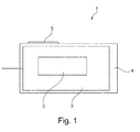
- a piston-cylinder assembly 1 is shown, as used in a master cylinder of a clutch actuation system of a motor vehicle.
- the master cylinder has a piston 2, which consists of a plastic and to which a target 3, which consists of an electrically conductive material, is arranged.
- a circuit board 5 is arranged, which carries a coil system.
- the target 3 is likewise moved past the coil system arranged on the circuit board 5.
- the coil system 9 arranged on the circuit board 5 is in Fig. 2 represented and simultaneously contrasted with a conventional coil system of the prior art.
- the coil system 9 according to the invention comprises two secondary coils 6, 7, of which the first secondary coil 6 has two turns with a crossover whose crossover axis is formed perpendicular to the measuring path.
- the second secondary coil 7 has three turns, wherein the adjacent turns are also crossed.
- the respective crossover axis is formed parallel to the measuring path.
- the areas covered by the first and second secondary coils 6, 7 approximately coincide, the width of both the first and second secondary coils 6, 7 being greatly shortened in the direction of the measuring path and being less than half the measuring path.
- Fig. 4 shows the arrangement of the first and the second secondary coil 6, 7 in the plane of, the two secondary coils 6, 7 enclosing the primary coil 8.
- the first and the second secondary coil 6, 7 are superimposed, wherein the length of the secondary coils 6, 7 of a width of the target 3, which scans the secondary coils 6, 7 as a result of the movement of the piston 2.
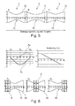
- the target 3 has a sidecut 13 in its axial extent.
- the outer contour 10 of the target 3A which extends axially in the direction of movement of the target 3A, is cosinusoidal.
- the target 3B shows the outer contour 11, which takes a convex course.
- the outer contour 12, starting from the centrally formed sidecut 13, is continuously led outwards.
- a continuous course of the outer contour 10, 11, 12 is provided.
- These targets 3 may be formed axisymmetric or rotationally symmetrical.
- the output signals S6, S7 of the secondary coils 6, 7 are modulated. This is in contrast to the prior art, where the output signals are modulated by the coil geometry.
- Fig. 6 Based on Fig. 6 to 8 the output signals A6, A7 of the secondary coils 6, 7 to be expected in the case of the different target geometries should be explained. It will be in Fig. 6 considered the geometry of the target 3A, wherein the movement sequence of the target 3A at the different positions A1, A2 and A3 on the basis of the output signals S6, S7 of the secondary coils 6, 7 is followed. In this case, the output signals S6, S7, the when sweeping the secondary coils 6, 7 are output by the geometry of the target 3A.
- the arctan Arctan which is formed from the quotient of the first output signal S6 of the first secondary coil 6 by the second output signal S7 of the second secondary coil 7, is linear in the cosinus shame design of the outer contour 10 of the target 3A and thus provides a reliable unique relationship between the arctangent and the position of the target 3A.
- the target position A1 is the initial overlap of the coil system 9 by the start of the target 3A.
- the position A2 represents the covering of the coil system 9 by the sidecut 13 of the target 3A, while the position A3 shows the cover of the coil system 9 through the end of the target 3A.
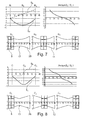
- Fig. 7 the geometry of the second target 3B is considered, where the outer contour 11 of the target 3B is convex.
- the output signals S6, S7 of the secondary coils 6, 7 corresponding to the three positions B1, B2 and B3 are considered.
- the first secondary coil 6 outputs an approximately linear output signal A6 over the measuring path, while the second secondary coil 7 outputs a slightly parabolic output signal S7, which reaches a maximum value at the position B2 where the sidecut 13 of the target 3B covers the coil system 9.
- the output signal for the geometry of the target 3C, at which the target 3C rises linearly on both sides starting from the sidecut 13, is in FIG Fig. 8 shown.
- the same positions C1, C2 and C3 of the target 3C to the secondary coils 6, 7 are considered.
- the first secondary coil 6 outputs an output signal S6 which rises abruptly in the region of the position C2, that is to say when the coil system 9 is covered by the sidecut 13 of the target 3C.
- the second secondary coil 7 once again displays an approximately parabolic output signal S7.
- the arctan Arctan from the quotient of the two output signals S6 / S7 of the secondary coils 6, 7 is also a continuous sloping curve, although slightly curved, but still gives a clear relationship between the Arctan and the target position.
- the inductive displacement sensor described allows a shortening of the length of the coils to one third of the measuring path by changing the target and coil geometry. As a result, the space requirement of such an inductive displacement sensor is dramatically reduced.
Landscapes
- Physics & Mathematics (AREA)
- General Physics & Mathematics (AREA)
- Measurement Of Length, Angles, Or The Like Using Electric Or Magnetic Means (AREA)
Abstract
Description
- Die Erfindung betrifft einen induktiven Wegsensor, umfassend ein Spulensystem mit einer planaren Primärspule zur Erzeugung eines Magnetfeldes und wenigstens zwei innerhalb der Primärspule angeordneten, sich überlagernden planaren Sekundärspulen zur Sensierung einer Position eines Targets, welches entlang der Sekundärspulen bewegbar ist, wobei die Sekundärspulen mit je einer Überkreuzung ausgebildet sind, sowie eine Kolben-Zylinder-Anordnung.
- Aus der
DE 10 2012 207 875 A1 ist eine Kolben-Zylinder-Anordnung bekannt, die einen Kolben aufweist, der axial beweglich in einem Zylinder angeordnet ist, wobei an der Kolben-Zylinder-Anordnung ein Sensorsystem zur induktiven Wegaufnahme positioniert ist. An dem Kolben sind wenigstens zwei Targets aus einem elektrisch leitenden Material angeordnet, die radial und axial voneinander beabstandet sind. An dem Zylinder ist ein induktiver Sensor angeordnet, der wenigstens eine Primärspule zur Erzeugung eines Magnetfeldes und wenigstens zwei innerhalb der Primärspule angeordnete Sekundärspulen zur Sensierung der Targetposition aufweist, wobei die Spulenachsen senkrecht zur Bewegungsrichtung des Kolbens verlaufen. - Schematisch ist ein solches induktives Messsystem in
Figur 9 dargestellt. Die Primärspule 8 erzeugt aufgrund eines vorgegebenen Stromflusses ein Magnetfeld, das in den Windungen der Sekundärspule 14 Spannungen induziert. Beide Spulen 8, 14 befinden sich auf einer Sensorplatine. Die Sekundärspule 14 ist so gestaltet, dass sich ihre Windung selbst kreuzt. Dadurch entstehen Bereiche mit gegensätzlichem Windungssinn, so dass die in den unterschiedlichen Bereichen induzierten Spannungen ebenfalls gegensätzliche Vorzeichen besitzen (siehe Pfeile P1). Die Flächen der Bereiche sind identisch, so dass der Betrag der Spannungen gleich ist. Im Basiszustand heben sich demnach alle induzierten Spannungen gegenseitig auf. Wird nun, wie inFig. 10 dargestellt, ein elektrisch leitender Körper in Form eines Targets 15 über die Sekundärspule 14 bewegt, ändert sich lokal das Magnetfeld, so dass sich die induzierten Spannungsanteile in der Sekundärspule 14 nicht mehr komplett gegenseitig aufheben. Es fließt ein Strom bzw. es kann eine Spannung gemessen werden, die inFig. 10 durch die Pfeile P2 verdeutlicht ist. - Wird nun das Target 15 über die Sensorplatine hinweg bewegt, ändern sich die Verhältnisse der lokal beeinflussten Magnetfelder in den einzelnen Bereichen. Dementsprechend ergibt sich für jede Targetposition ein anderer Strom. Um eine eindeutige Wegmessung zu ermöglichen, ist eine zweite Sekundärspule 16 eingesetzt, die zu der ersten axial versetzt ist (
Fig. 11 ). - Zur Auswertung dieser Sensorsignale S14, S16 der zwei Sekundärspulen 14, 16 wird ein Arcustangens des Quotienten der beiden Spulensignale S14, S16 gebildet. Sind die Signale S14, S16 der beiden Sekundärspulen 14, 16 um 90° phasenverschoben, wie es in
Fig. 12 dargestellt ist, so ergibt sich aus der Berechnung des Arcustangens Arctan ein näherungsweiser linearer Verlauf über den gesamten, von dem Target 15 zurückgelegten Messweg. Die Ausgangssignale S14, S16 der Sekundärspulen 14, 16 werden hierbei durch die Geometrie des Sekundärspulen 14, 16 moduliert. - Das beschriebene induktive Messsystem erfordert relativ viel Bauraum, da die Sensorplatine mindestens so lang sein muss wie der zu detektierende Messweg. Bei der Anwendung in einem Kraftfahrzeug steht aber nur begrenzt Bauraum zur Verfügung, weshalb solche induktiven Messsystems dort nur beschränkt einsetzbar sind.
- Der Erfindung liegt die Aufgabe zugrunde, einen induktiven Wegsensor sowie eine Kolben-Zylinder-Anordnung anzugeben, welcher nur eine geringere Sensorlänge aufweist und trotzdem ein eindeutiges Messsignal abgibt.
- Erfindungsgemäß ist die Aufgabe dadurch gelöst, dass die erste Sekundärspule eine Überkreuzung aufweist, die quer zur Bewegungsrichtung des Targets ausgebildet ist, während die zweite Sekundärspule eine Überkreuzung besitzt, welche parallel zur Bewegungsrichtung des Targets verläuft und das Target in seiner axialen Ausdehnung tailliert ausgebildet ist. Durch die Veränderung der Target- und Spulengeometrie wird der induktive Wegsensor dahingehend verbessert, dass die Länge des Wegsensors nur ein Drittel des von dem Target überschrittenen Messweges beträgt und somit den Bauraumbeschränkungen der Kolben-Zylinder-Anordnung in einem Kraftfahrzeug entgegenkommt. Aufgrund des vorgeschlagenen induktiven Wegsensors kann die Platine, die den Wegsensor trägt, verkürzt werden, was eine geringere Ausdehnung in axialer Richtung nach sich zieht. Somit ist der Einsatz eines induktiven Wegsensors in einer Kolben-Zylinder-Anordnung auch dann möglich, wenn bei dem System der Bauraum in axialer Richtung begrenzt wird. Dies ist insbesondere dadurch möglich, da die Ausgangssignale der Sekundärspulen des induktiven Wegsensors durch die Targetgeometrie moduliert werden.
- Vorteilhafterweise weisen die erste, mindestens eine Überkreuzung aufweisende Sekundärspule und die zweite, mindestens zwei Überkreuzungen aufweisende Sekundärspule die gleichen Abmaße auf und überdecken sich annähernd vollständig, wobei die Breite der ersten und der zweiten Sekundärspule kleiner einem halben, von dem Target zurücklegbaren Messweg ist. Dadurch, dass die erste Sekundärspule zum Messweg hin verkürzt ist und die Orientierung der zweiten Sekundärspule um 90° gedreht ist, lassen sich auch bei einer verkürzten Sensorstruktur eindeutige Ausgangssignale, welches der Position des Targets zuordenbar ist, an den Sekundärspulen abnehmen.
- In einer Ausgestaltung decken die zwei Windungen der ersten Sekundärspule annähernd gleich große Flächen ab, während die zwei äußeren Windungen der zweiten Sekundärspule gleich große Flächen abdecken und die mittlere Windung der zweiten Sekundärspule eine doppelt so große Fläche umfasst wie jede der äußeren Windungen der zweiten Sekundärspule. Durch diese Geometrie wird sichergestellt, dass der Arcustangens des Quotienten aus den beiden Ausgangssignalen der Sekundärspulen annähernd linear ist und somit eine eindeutige Zuordnung zur Position des Targets herstellbar ist.
- In einer Variante ist die Taillierung des Targets annähernd mittig ausgebildet, wobei die axial verlaufende, die Taillierung umfassende Außenkontur des Targets einen stetigen Verlauf aufweist. Mittels dieses stetigen Verlaufes werden an den beiden Sekundärspulen ein kontinuierliche, um 90° versetzte Ausgangssignale abgenommen.
- Der stetige Verlauf der Außenkontur des Targets kann dabei durch unterschiedliche Geometrien erreicht werden. So kann die, die Taillierung umfassende Außenkontur in ihrem Verlauf cosinusartig oder konvex ausgebildet sein. In einer weiteren Alternative steigt die Außenkontur des Targets ausgehend von der Taillierung beidseitig zu dieser linear an.
- In einer Variante stimmt eine Breite des Targets annähernd mit einer Länge der überlagerten ersten und zweiten Sekundärspule überein. Dadurch werden die Geometrien des Targets und der Sekundärspulen optimal aufeinander abgestimmt, wodurch kontinuierliche Ausgangssignale der Sekundärspulen erhalten werden, die um 90° versetzt sind.
- Eine Weiterbildung der Erfindung betrifft eine Kolben-Zylinder-Anordnung, insbesondere zur Verwendung in einem hydraulischen System zur Kupplungsbetätigung in einem Fahrzeug, mit einem Kolben, welcher axial beweglich in einem Zylinder angeordnet ist, und mit einem induktiven Wegsensor, dessen Target fest am Kolben positioniert ist und dessen Spulensystem an dem Zylinder angeordnet ist. Bei einer Kolben-Zylinder-Anordnung, bei welcher ein Bauraumbedarf eines induktiven Wegsensors stark reduziert werden kann, ist der induktive Wegsensor nach mindestens einem der in dieser Schutzrechtsanmeldung beschriebenen Merkmale ausgebildet.
- Die Erfindung lässt zahlreiche Ausführungsbeispiele zu. Eine davon soll anhand der in der Zeichnung dargestellten Figuren näher erläutert werden.
- Es zeigen:
- Fig. 1:
- ein Ausführungsbeispiel für eine Kolben-Zylinder-Anordnung,
- Fig. 2:
- ein Ausführungsbeispiel eines erfindungsgemäßen Spulensystems,
- Fig. 3:
- eine Prinzipdarstellung der geometrischen Abmaße des erfindungsgemäßen Spulensystems nach
Fig. 2 , - Fig. 4:
- ein erfindungsgemäß überlagertes Spulensystem nach
Fig. 1 , - Fig. 5:
- drei Ausführungsbeispiele für eine mögliche Targetgeometrie,
- Fig. 6:
- Darstellung der Ausgangssignale der Sekundärspulen für eine erste Targetgeometrie,
- Fig. 7:
- Darstellung der Ausgangssignale der Sekundärspulen für eine zweite Targetgeometrie,
- Fig. 8:
- Darstellung der Ausgangssignale der Sekundärspulen für eine dritte Targetgeometrie,
- Fig. 9:
- eine Spulengeometrie eines induktiven Wegsensors nach dem Stand der Technik,
- Fig. 10:
- ein induktiver Wegsensor nach dem Stand der Technik,
- Fig. 11:
- Konstellationen mit zwei Sekundärspulen nach dem Stand der Technik,
- Fig. 12:
- ein typisches Ausgangssignal des induktiven Wegsensors nach dem Stand der Technik.
- In
Fig. 1 ist eine Kolben-Zylinder-Anordnung 1 dargestellt, wie sie in einem Geberzylinder eines Kupplungsbetätigungssystems eines Kraftfahrzeuges zur Anwendung kommt. Der Geberzylinder weist einen Kolben 2 auf, welcher aus einem Kunststoff besteht und an welchen ein Target 3, das aus einem elektrisch leitenden Material besteht, angeordnet ist. An der Außenwand eines Zylinders 4 der Kolben-Zylinder-Anordnung 1 ist eine Platine 5 angeordnet, die ein Spulensystem trägt. Bei der Bewegung des Kolbens 2 wird ebenfalls das Target 3 an dem auf der Platine 5 angeordneten Spulensystem vorbeibewegt. - Das auf der Platine 5 angeordnet Spulensystem 9 ist in
Fig. 2 dargestellt und gleichzeitig einem gebräuchlichen Spulensystem des Standes der Technik gegenübergestellt. Das erfindungsgemäße Spulensystem 9 umfasst zwei Sekundärspulen 6, 7, wovon die erste Sekundärspule 6 zwei Windungen mit einer Überkreuzung aufweist, deren Überkreuzungsachse senkrecht zum Messweg ausgebildet ist. Die zweite Sekundärspule 7 weist drei Windungen auf, wobei die nebeneinanderliegenden Windungen ebenfalls gekreuzt sind. Bei der zweiten Sekundärspule 7 ist die jeweilige Überkreuzungsachse parallel zum Messweg ausgebildet. Die von der ersten und der zweiten Sekundärspule 6, 7 abgedeckten Flächen stimmen annähernd überein, wobei in Richtung des Messweges die Breite sowohl der ersten als auch der zweiten Sekundärspule 6, 7 stark verkürzt ist und weniger als die Hälfte des Messweges beträgt. - Wie aus
Fig. 3 zu ersehen, überdecken die beiden spiegelsymmetrisch ausgebildeten Windungen 61, 62 der ersten Sekundärspule 6 gleiche Flächen und weisen jeweils eine Breite a auf. Die zweite Sekundärspule 7 , welche aus drei Windungen 71, 72, 73 besteht, weist eine mittlere Windung 72 auf, welche zweimal so breit ist, wie jede der äußeren Windungen 71, 73. -
Fig. 4 zeigt die Anordnung der ersten und der zweiten Sekundärspule 6, 7 in der Ebene der, die beiden Sekundärspulen 6, 7 umschließenden Primärspule 8. Dabei liegen die erste und die zweite Sekundärspule 6, 7 übereinander, wobei die Länge der Sekundärspulen 6, 7 einer Breite des Targets 3 entspricht, welches die Sekundärspulen 6, 7 infolge der Bewegung des Kolbens 2 abtastet. - Mögliche Geometrien des Targets 3 sind in
Fig. 5 dargestellt. In jedem Fall weist das Target 3 in seiner axialen Ausdehnung eine Taillierung 13 auf. Im Fall des Targets 3A ist die Außenkontur 10 des Targets 3A, welche sich axial in Bewegungsrichtung des Targets 3A erstreckt, cosinusförmig ausgebildet. Das Target 3B zeigt die Außenkontur 11, welche einen konvexen Verlauf nimmt. Im Fall des Targets 3C ist die Außenkontur 12 ausgehend von der mittig ausgebildeten Taillierung 13 stetig ansteigend nach außen geführt. In allen drei Fällen ist ein stetiger Verlauf der Außenkontur 10, 11, 12 vorgesehen. Diese Targets 3 können achssymmetrisch oder rotationssymmetrisch ausgebildet sein. Mittels solcher Targetgeometrien werden die Ausgangssignale S6, S7 der Sekundärspulen 6, 7 moduliert. Dies steht im Gegensatz zum Stand der Technik, wo die Ausgangssignale durch die Spulengeometrie moduliert werden. - Anhand der
Fig. 6 bis 8 sollen die, bei den unterschiedlichen Targetgeometrien zu erwartenden Ausgangssignale A6, A7 der Sekundärspulen 6, 7 erläutert werden. Dabei wird inFig. 6 die Geometrie des Targets 3A betrachtet, wobei der Bewegungsablauf des Targets 3A an den verschiedenen Positionen A1, A2 und A3 an Hand der Ausgangssignale S6, S7 der Sekundärspulen 6, 7 verfolgt wird. Dabei sind die Ausgangssignale S6, S7, die beim Überstreichen der Sekundärspulen 6, 7 durch die Geometrie des Targets 3A ausgegeben werden, dargestellt. Der Arcustangens Arctan, welcher aus dem Quotienten des ersten Ausgangssignals S6 der ersten Sekundärspule 6 durch das zweite Ausgangssignal S7 der zweiten Sekundärspule 7 gebildet wird, ist bei der cosinusähnlichen Gestaltung der Außenkontur 10 des Targets 3A linear und stellt somit einen zuverlässigen eindeutigen Zusammenhang zwischen dem Arcustangens und der Position des Targets 3A dar. Die Targetposition A1 besteht in der erstmalige Überdeckung des Spulensystems 9 durch den Beginn des Targets 3A. Die Position A2 stellt die Überdeckung des Spulensystems 9 durch die Taillierung 13 des Targets 3A dar, während die Position A3 die Abdeckung des Spulensystems 9 durch das Ende des Targets 3A zeigt. - In
Fig. 7 wird die Geometrie des zweiten Targets 3B betrachtet, wo die Außenkontur 11 des Targets 3B konvex ausgebildet ist. Auch hier werden die den drei Positionen B1, B2 und B3 entsprechende Ausgangssignale S6, S7 der Sekundärspulen 6, 7 betrachtet. Dabei gibt die erste Sekundärspule 6 ein annähernd lineares Ausgangssignal A6 über dem Messweg aus, während die zweite Sekundärspule 7 ein leicht parabelförmiges Ausgangssignal S7 ausgibt, welches an der Position B2, wo die Taillierung 13 des Targets 3B das Spulensystem 9 überdeckt, einen Maximalwert erreicht. Der Arcustangens des Quotienten des Ausgangssignals S6 der ersten Sekundärspule 6 durch das Ausgangssignal S7 der zweiten Sekundärspule 7 ergibt dabei eine leicht gewölbte abfallende Kurve, welche aber stetig verläuft, so dass auch hier eine eindeutige Zuordnung des Arcustangens zu dem, vom Target 3B zurückgelegten Messweg möglich ist. - Das Ausgangssignal für die Geometrie des Targets 3C, bei welcher das Target 3C ausgehend von der Taillierung 13 beidseitig linear ansteigt, ist in
Fig. 8 dargestellt. Auch hier werden, wie in den anderen beiden Fällen, die gleichen Positionen C1, C2 und C3 des Targets 3C zu den Sekundärspulen 6, 7 betrachtet. Wie ersichtlich, gibt die erste Sekundärspule 6 ein Ausgangssignal S6 ab, welches im Bereich der Position C2, also bei der Überdeckung des Spulensystems 9 durch die Taillierung 13 des Targets 3C sprunghaft ansteigt, Die zweite Sekundärspule 7 zeigt wiederum ein annähernd parabelförmiges Ausgangssignal S7. Der Arcustangens Arctan aus dem Quotienten der beiden Ausgangssignale S6/S7 der Sekundärspulen 6, 7 ist ebenfalls eine stetig abfallende Kurve, die zwar leicht gewölbt, aber trotzdem einen eindeutigen Zusammenhang zwischen dem Arctan und der Targetposition widergibt. Der beschriebene induktive Wegsensor erlaubt durch eine Veränderung der Target- und Spulengeometrie eine Verkürzung der Länge der Spulen auf ein Drittel des Messweges. Hierdurch wird der Bauraumbedarf eines solchen induktiven Wegsensors dramatisch verkleinert. Darüber hinaus erfolgt die Modulation der Ausgangssignale S6, S7 der Sekundärspulen 6, 7 durch die Geometrie des Targets 3. -
- 1
- Kolben-Zylinder-Anordnung
- 2
- Kolben
- 3
- Target
- 4
- Zylinder
- 5
- Platine
- 6
- Sekundarspule
- 7
- Sekundärspule
- 8
- Primärspule
- 9
- Spulensystem
- 10
- Außenkontur
- 11
- Außenkontur
- 12
- Außenkontur
- 13
- Taillierung
- 14
- Sekundärspule
- 15
- Target
- 16
- Sekundärspule
- 61
- Windung
- 62
- Windung
- 71
- Windung
- 72
- Windung
- 73
- Windung
Claims (9)
- Induktiver Wegsensor, umfassend ein Spulensystem (9) mit einer planaren Primärspule (8) zur Erzeugung eines Magnetfeldes und wenigstens zwei innerhalb der Primärspule (8) angeordneten, sich überlagernden planaren Sekundärspulen (6, 7) zur Sensierung einer Position eines Targets (3), welches entlang der Sekundärspulen (6, 7) bewegbar ist, wobei die Sekundärspulen (6, 7) mit je einer Überkreuzung ausgebildet sind, dadurch gekennzeichnet, dass die erste Sekundärspule (6) eine Überkreuzung aufweist, die quer zur Bewegungsrichtung des Targets (3) ausgebildet ist, während die zweite Sekundärspule (7) eine Überkreuzung besitzt, welche parallel zur Bewegungsrichtung des Targets (3) verläuft und das Target (3) in seiner axialen Ausdehnung tailliert ausgebildet ist.
- Induktiver Wegsensor nach Anspruch 1, dadurch gekennzeichnet, dass die erste, zwei Windungen (61, 62) aufweisende Sekundärspule (6) und die zweite, drei Windungen (71, 72, 73) aufweisende Sekundärspule (7) die gleichen Abmaße aufweisen und sich annähernd vollständig überdecken, wobei die Breite der ersten und der zweiten Sekundärspule (6, 7) kleiner einem halben, von dem Target (3) zurücklegbaren Messweg ist.
- Induktiver Wegsensor nach Anspruch 1 oder 2, dadurch gekennzeichnet, dass die zwei Windungen (61, 62) der ersten Sekundärspule (6) annähernd gleich große Flächen abdecken, während die zwei äußeren Windungen (71, 73) der zweiten Sekundärspule (7) gleich große Flächen abdecken und die mittlere Windung (72) der zweiten Sekundärspule (7) eine doppelt so große Fläche umfasst wie jede der äußeren Windungen (71, 73) der zweiten Sekundärspule (7).
- Induktiver Wegsensor nach Anspruch 1, 2 oder 3, dadurch gekennzeichnet, dass die Taillierung (13) des Targets (3) annähernd mittig am Target (3) ausgebildet ist, wobei die axial verlaufende, die Taillierung (13) umfassende Außenkontur (10, 11, 12) des Targets (3) einen stetigen Verlauf aufweist.
- Induktiver Wegsensor nach Anspruch 4, dadurch gekennzeichnet, dass die, die Taillierung (13) umfassende Außenkontur (10) des Targets (3A) in ihrem axialen Verlauf cosinusähnlich ausgebildet ist.
- Induktiver Wegsensor nach Anspruch 4, dadurch gekennzeichnet, dass die, die Taillierung (13) umfassende Außenkontur (11) des Targets (3B) in ihrem axialen Verlauf konvex ausgebildet ist.
- Induktiver Wegsensor nach Anspruch 4, dadurch gekennzeichnet, dass die Außenkontur (12) des Targets (3C) ausgehend von der Taillierung (13) beidseitig zu dieser linear ansteigt.
- Induktiver Wegsensor nach mindestens einem der vorhergehenden Ansprüche, dadurch gekennzeichnet, dass eine Breite des Targets (3) annähernd mit einer Länge der überlagerten ersten und zweiten Sekundärspule (6, 7) übereinstimmt.
- Kolben-Zylinder-Anordnung, insbesondere zur Verwendung in einem hydraulischen System zur Kupplungsbetätigung in einem Fahrzeug, mit einem Kolben (2), welcher axial beweglich in einem Zylinder (4) angeordnet ist, mit einem induktiven Wegsensor, dessen Target (3) fest am Kolben (2) positioniert ist und dessen Spulensystem (9) an dem Zylinder (4) angeordnet ist, dadurch gekennzeichnet, dass der induktive Wegsensor nach mindestens einem der vorhergehenden Ansprüche ausgebildet ist.
Applications Claiming Priority (1)
| Application Number | Priority Date | Filing Date | Title |
|---|---|---|---|
| DE102014208577 | 2014-05-07 |
Publications (2)
| Publication Number | Publication Date |
|---|---|
| EP2947425A1 true EP2947425A1 (de) | 2015-11-25 |
| EP2947425B1 EP2947425B1 (de) | 2017-07-26 |
Family
ID=52824148
Family Applications (1)
| Application Number | Title | Priority Date | Filing Date |
|---|---|---|---|
| EP15163314.6A Active EP2947425B1 (de) | 2014-05-07 | 2015-04-13 | Induktiver wegsensor und kolben-zylinder-anordnung |
Country Status (2)
| Country | Link |
|---|---|
| EP (1) | EP2947425B1 (de) |
| DE (1) | DE102015206495A1 (de) |
Citations (6)
| Publication number | Priority date | Publication date | Assignee | Title |
|---|---|---|---|---|
| US20050030010A1 (en) * | 2001-10-30 | 2005-02-10 | Jones Ross Peter | Sensing apparatus and method |
| DE102006041934A1 (de) * | 2006-09-07 | 2008-03-27 | Werner Turck Gmbh & Co. Kg | Vorrichtung zur Bestimmung der Position eines Beeinflussungselementes |
| US20100117632A1 (en) * | 2008-11-12 | 2010-05-13 | Aisan Kogyo Kabushiki Kaisha | Resolver |
| DE102012207875A1 (de) | 2011-06-01 | 2012-12-06 | Schaeffler Technologies AG & Co. KG | Kolben-Zylinder-Anordnung |
| DE102012207778A1 (de) * | 2011-06-01 | 2012-12-06 | Schaeffler Technologies AG & Co. KG | Kolben-Zylinder-Anordnung mit Wegmess-Sensor |
| US20140117980A1 (en) * | 2012-06-13 | 2014-05-01 | Cambridge Integrated Circuits Limited | Position sensing transducer |
-
2015
- 2015-04-13 DE DE102015206495.6A patent/DE102015206495A1/de not_active Withdrawn
- 2015-04-13 EP EP15163314.6A patent/EP2947425B1/de active Active
Patent Citations (6)
| Publication number | Priority date | Publication date | Assignee | Title |
|---|---|---|---|---|
| US20050030010A1 (en) * | 2001-10-30 | 2005-02-10 | Jones Ross Peter | Sensing apparatus and method |
| DE102006041934A1 (de) * | 2006-09-07 | 2008-03-27 | Werner Turck Gmbh & Co. Kg | Vorrichtung zur Bestimmung der Position eines Beeinflussungselementes |
| US20100117632A1 (en) * | 2008-11-12 | 2010-05-13 | Aisan Kogyo Kabushiki Kaisha | Resolver |
| DE102012207875A1 (de) | 2011-06-01 | 2012-12-06 | Schaeffler Technologies AG & Co. KG | Kolben-Zylinder-Anordnung |
| DE102012207778A1 (de) * | 2011-06-01 | 2012-12-06 | Schaeffler Technologies AG & Co. KG | Kolben-Zylinder-Anordnung mit Wegmess-Sensor |
| US20140117980A1 (en) * | 2012-06-13 | 2014-05-01 | Cambridge Integrated Circuits Limited | Position sensing transducer |
Also Published As
| Publication number | Publication date |
|---|---|
| DE102015206495A1 (de) | 2015-11-12 |
| EP2947425B1 (de) | 2017-07-26 |
Similar Documents
| Publication | Publication Date | Title |
|---|---|---|
| WO2021239175A1 (de) | Positionssensor, zentralausrücker und kupplungseinrichtung | |
| DE102007008870A1 (de) | Anordnung und Verfahren zur Absolutbestimmung der Linearposition oder der durch einen Winkel ausgedrückten Drehposition | |
| EP2715152B1 (de) | Kolben-zylinder-anordnung mit wegmess-sensor | |
| DE102009047222A1 (de) | Sensoranordnung zum Ermitteln eines Drehmoments und zur Indexerkennung | |
| DE102011102796A1 (de) | Positionssensor, Aktor-Sensor-Vorrichtung und Verfahren zur induktiven Erfassung einer Position | |
| DE60215414T2 (de) | Apparat zur Erfassung einer relativen Winkelpositionsänderung | |
| WO2014111218A1 (de) | Spulenanordnung mit zwei spulen | |
| EP2884238A1 (de) | Induktiver Drehwinkelsensor mit einer kreissegmentförmigen Erreger- und Empfangsspule | |
| EP2942606A1 (de) | Induktiver wegsensor und kolbenzylinder-anordnung | |
| EP0936444A1 (de) | Anordnung zur berührungslosen Positionsbestimmung eines Messobjektes, vorzugsweise einer Schaltwelle eines Kraftfahrzeuggetriebes | |
| EP1980427A2 (de) | Feder-Einheit mit Sensor für den Federweg | |
| EP2149784A1 (de) | Magnetisches Wegsensorsystem | |
| WO2021249776A1 (de) | Induktiver positionssensor | |
| WO1993004341A2 (de) | Messeinrichtung zur berührungsfreien bestimmung des wegs oder des drehwinkels eines bauteils | |
| DE102014218982A1 (de) | Sensoranordnung zur Weg- und/oder Winkelmessung | |
| EP1685365A2 (de) | Berührungslos arbeitendes wegmesssystem | |
| EP2947425B1 (de) | Induktiver wegsensor und kolben-zylinder-anordnung | |
| DE4243022C2 (de) | Meßeinrichtung zur Bestimmung eines Drehwinkels | |
| DE102009038087A1 (de) | Kugelgewindetrieb | |
| EP3427010A1 (de) | Kipptoleranter wegsensor | |
| EP2884237A1 (de) | Induktiver Drehwinkelsensor | |
| DE102006061771B4 (de) | Magnetischer Wegsensor mit linearer Kennlinie des Ausgangssignals | |
| DE202008008477U1 (de) | Stabförmiger Linearsensor | |
| DE2738011C3 (de) | Induktiver Meßtransformator | |
| DE102012207875A1 (de) | Kolben-Zylinder-Anordnung |
Legal Events
| Date | Code | Title | Description |
|---|---|---|---|
| PUAI | Public reference made under article 153(3) epc to a published international application that has entered the european phase |
Free format text: ORIGINAL CODE: 0009012 |
|
| AK | Designated contracting states |
Kind code of ref document: A1 Designated state(s): AL AT BE BG CH CY CZ DE DK EE ES FI FR GB GR HR HU IE IS IT LI LT LU LV MC MK MT NL NO PL PT RO RS SE SI SK SM TR |
|
| AX | Request for extension of the european patent |
Extension state: BA ME |
|
| 17P | Request for examination filed |
Effective date: 20160525 |
|
| RBV | Designated contracting states (corrected) |
Designated state(s): AL AT BE BG CH CY CZ DE DK EE ES FI FR GB GR HR HU IE IS IT LI LT LU LV MC MK MT NL NO PL PT RO RS SE SI SK SM TR |
|
| R17P | Request for examination filed (corrected) |
Effective date: 20160525 |
|
| GRAP | Despatch of communication of intention to grant a patent |
Free format text: ORIGINAL CODE: EPIDOSNIGR1 |
|
| INTG | Intention to grant announced |
Effective date: 20170221 |
|
| GRAJ | Information related to disapproval of communication of intention to grant by the applicant or resumption of examination proceedings by the epo deleted |
Free format text: ORIGINAL CODE: EPIDOSDIGR1 |
|
| INTC | Intention to grant announced (deleted) | ||
| GRAP | Despatch of communication of intention to grant a patent |
Free format text: ORIGINAL CODE: EPIDOSNIGR1 |
|
| INTG | Intention to grant announced |
Effective date: 20170516 |
|
| GRAS | Grant fee paid |
Free format text: ORIGINAL CODE: EPIDOSNIGR3 |
|
| GRAA | (expected) grant |
Free format text: ORIGINAL CODE: 0009210 |
|
| AK | Designated contracting states |
Kind code of ref document: B1 Designated state(s): AL AT BE BG CH CY CZ DE DK EE ES FI FR GB GR HR HU IE IS IT LI LT LU LV MC MK MT NL NO PL PT RO RS SE SI SK SM TR |
|
| REG | Reference to a national code |
Ref country code: GB Ref legal event code: FG4D Free format text: NOT ENGLISH |
|
| REG | Reference to a national code |
Ref country code: CH Ref legal event code: EP |
|
| REG | Reference to a national code |
Ref country code: AT Ref legal event code: REF Ref document number: 912740 Country of ref document: AT Kind code of ref document: T Effective date: 20170815 |
|
| REG | Reference to a national code |
Ref country code: IE Ref legal event code: FG4D Free format text: LANGUAGE OF EP DOCUMENT: GERMAN |
|
| REG | Reference to a national code |
Ref country code: DE Ref legal event code: R096 Ref document number: 502015001495 Country of ref document: DE |
|
| REG | Reference to a national code |
Ref country code: NL Ref legal event code: MP Effective date: 20170726 |
|
| REG | Reference to a national code |
Ref country code: LT Ref legal event code: MG4D |
|
| PG25 | Lapsed in a contracting state [announced via postgrant information from national office to epo] |
Ref country code: FI Free format text: LAPSE BECAUSE OF FAILURE TO SUBMIT A TRANSLATION OF THE DESCRIPTION OR TO PAY THE FEE WITHIN THE PRESCRIBED TIME-LIMIT Effective date: 20170726 Ref country code: NL Free format text: LAPSE BECAUSE OF FAILURE TO SUBMIT A TRANSLATION OF THE DESCRIPTION OR TO PAY THE FEE WITHIN THE PRESCRIBED TIME-LIMIT Effective date: 20170726 Ref country code: HR Free format text: LAPSE BECAUSE OF FAILURE TO SUBMIT A TRANSLATION OF THE DESCRIPTION OR TO PAY THE FEE WITHIN THE PRESCRIBED TIME-LIMIT Effective date: 20170726 Ref country code: LT Free format text: LAPSE BECAUSE OF FAILURE TO SUBMIT A TRANSLATION OF THE DESCRIPTION OR TO PAY THE FEE WITHIN THE PRESCRIBED TIME-LIMIT Effective date: 20170726 Ref country code: SE Free format text: LAPSE BECAUSE OF FAILURE TO SUBMIT A TRANSLATION OF THE DESCRIPTION OR TO PAY THE FEE WITHIN THE PRESCRIBED TIME-LIMIT Effective date: 20170726 Ref country code: NO Free format text: LAPSE BECAUSE OF FAILURE TO SUBMIT A TRANSLATION OF THE DESCRIPTION OR TO PAY THE FEE WITHIN THE PRESCRIBED TIME-LIMIT Effective date: 20171026 |
|
| PG25 | Lapsed in a contracting state [announced via postgrant information from national office to epo] |
Ref country code: GR Free format text: LAPSE BECAUSE OF FAILURE TO SUBMIT A TRANSLATION OF THE DESCRIPTION OR TO PAY THE FEE WITHIN THE PRESCRIBED TIME-LIMIT Effective date: 20171027 Ref country code: BG Free format text: LAPSE BECAUSE OF FAILURE TO SUBMIT A TRANSLATION OF THE DESCRIPTION OR TO PAY THE FEE WITHIN THE PRESCRIBED TIME-LIMIT Effective date: 20171026 Ref country code: PL Free format text: LAPSE BECAUSE OF FAILURE TO SUBMIT A TRANSLATION OF THE DESCRIPTION OR TO PAY THE FEE WITHIN THE PRESCRIBED TIME-LIMIT Effective date: 20170726 Ref country code: RS Free format text: LAPSE BECAUSE OF FAILURE TO SUBMIT A TRANSLATION OF THE DESCRIPTION OR TO PAY THE FEE WITHIN THE PRESCRIBED TIME-LIMIT Effective date: 20170726 Ref country code: IS Free format text: LAPSE BECAUSE OF FAILURE TO SUBMIT A TRANSLATION OF THE DESCRIPTION OR TO PAY THE FEE WITHIN THE PRESCRIBED TIME-LIMIT Effective date: 20171126 Ref country code: LV Free format text: LAPSE BECAUSE OF FAILURE TO SUBMIT A TRANSLATION OF THE DESCRIPTION OR TO PAY THE FEE WITHIN THE PRESCRIBED TIME-LIMIT Effective date: 20170726 Ref country code: ES Free format text: LAPSE BECAUSE OF FAILURE TO SUBMIT A TRANSLATION OF THE DESCRIPTION OR TO PAY THE FEE WITHIN THE PRESCRIBED TIME-LIMIT Effective date: 20170726 |
|
| PG25 | Lapsed in a contracting state [announced via postgrant information from national office to epo] |
Ref country code: DK Free format text: LAPSE BECAUSE OF FAILURE TO SUBMIT A TRANSLATION OF THE DESCRIPTION OR TO PAY THE FEE WITHIN THE PRESCRIBED TIME-LIMIT Effective date: 20170726 Ref country code: CZ Free format text: LAPSE BECAUSE OF FAILURE TO SUBMIT A TRANSLATION OF THE DESCRIPTION OR TO PAY THE FEE WITHIN THE PRESCRIBED TIME-LIMIT Effective date: 20170726 Ref country code: RO Free format text: LAPSE BECAUSE OF FAILURE TO SUBMIT A TRANSLATION OF THE DESCRIPTION OR TO PAY THE FEE WITHIN THE PRESCRIBED TIME-LIMIT Effective date: 20170726 |
|
| REG | Reference to a national code |
Ref country code: DE Ref legal event code: R097 Ref document number: 502015001495 Country of ref document: DE |
|
| REG | Reference to a national code |
Ref country code: FR Ref legal event code: PLFP Year of fee payment: 4 |
|
| PG25 | Lapsed in a contracting state [announced via postgrant information from national office to epo] |
Ref country code: IT Free format text: LAPSE BECAUSE OF FAILURE TO SUBMIT A TRANSLATION OF THE DESCRIPTION OR TO PAY THE FEE WITHIN THE PRESCRIBED TIME-LIMIT Effective date: 20170726 Ref country code: EE Free format text: LAPSE BECAUSE OF FAILURE TO SUBMIT A TRANSLATION OF THE DESCRIPTION OR TO PAY THE FEE WITHIN THE PRESCRIBED TIME-LIMIT Effective date: 20170726 Ref country code: SM Free format text: LAPSE BECAUSE OF FAILURE TO SUBMIT A TRANSLATION OF THE DESCRIPTION OR TO PAY THE FEE WITHIN THE PRESCRIBED TIME-LIMIT Effective date: 20170726 Ref country code: SK Free format text: LAPSE BECAUSE OF FAILURE TO SUBMIT A TRANSLATION OF THE DESCRIPTION OR TO PAY THE FEE WITHIN THE PRESCRIBED TIME-LIMIT Effective date: 20170726 |
|
| PLBE | No opposition filed within time limit |
Free format text: ORIGINAL CODE: 0009261 |
|
| STAA | Information on the status of an ep patent application or granted ep patent |
Free format text: STATUS: NO OPPOSITION FILED WITHIN TIME LIMIT |
|
| 26N | No opposition filed |
Effective date: 20180430 |
|
| PG25 | Lapsed in a contracting state [announced via postgrant information from national office to epo] |
Ref country code: SI Free format text: LAPSE BECAUSE OF FAILURE TO SUBMIT A TRANSLATION OF THE DESCRIPTION OR TO PAY THE FEE WITHIN THE PRESCRIBED TIME-LIMIT Effective date: 20170726 |
|
| PG25 | Lapsed in a contracting state [announced via postgrant information from national office to epo] |
Ref country code: MT Free format text: LAPSE BECAUSE OF FAILURE TO SUBMIT A TRANSLATION OF THE DESCRIPTION OR TO PAY THE FEE WITHIN THE PRESCRIBED TIME-LIMIT Effective date: 20170726 |
|
| PG25 | Lapsed in a contracting state [announced via postgrant information from national office to epo] |
Ref country code: MC Free format text: LAPSE BECAUSE OF FAILURE TO SUBMIT A TRANSLATION OF THE DESCRIPTION OR TO PAY THE FEE WITHIN THE PRESCRIBED TIME-LIMIT Effective date: 20170726 |
|
| REG | Reference to a national code |
Ref country code: CH Ref legal event code: PL |
|
| REG | Reference to a national code |
Ref country code: BE Ref legal event code: MM Effective date: 20180430 |
|
| REG | Reference to a national code |
Ref country code: IE Ref legal event code: MM4A |
|
| PG25 | Lapsed in a contracting state [announced via postgrant information from national office to epo] |
Ref country code: LU Free format text: LAPSE BECAUSE OF NON-PAYMENT OF DUE FEES Effective date: 20180413 |
|
| PG25 | Lapsed in a contracting state [announced via postgrant information from national office to epo] |
Ref country code: BE Free format text: LAPSE BECAUSE OF NON-PAYMENT OF DUE FEES Effective date: 20180430 Ref country code: LI Free format text: LAPSE BECAUSE OF NON-PAYMENT OF DUE FEES Effective date: 20180430 Ref country code: CH Free format text: LAPSE BECAUSE OF NON-PAYMENT OF DUE FEES Effective date: 20180430 |
|
| PG25 | Lapsed in a contracting state [announced via postgrant information from national office to epo] |
Ref country code: IE Free format text: LAPSE BECAUSE OF NON-PAYMENT OF DUE FEES Effective date: 20180413 |
|
| GBPC | Gb: european patent ceased through non-payment of renewal fee |
Effective date: 20190413 |
|
| PG25 | Lapsed in a contracting state [announced via postgrant information from national office to epo] |
Ref country code: GB Free format text: LAPSE BECAUSE OF NON-PAYMENT OF DUE FEES Effective date: 20190413 |
|
| PG25 | Lapsed in a contracting state [announced via postgrant information from national office to epo] |
Ref country code: TR Free format text: LAPSE BECAUSE OF FAILURE TO SUBMIT A TRANSLATION OF THE DESCRIPTION OR TO PAY THE FEE WITHIN THE PRESCRIBED TIME-LIMIT Effective date: 20170726 |
|
| PG25 | Lapsed in a contracting state [announced via postgrant information from national office to epo] |
Ref country code: PT Free format text: LAPSE BECAUSE OF FAILURE TO SUBMIT A TRANSLATION OF THE DESCRIPTION OR TO PAY THE FEE WITHIN THE PRESCRIBED TIME-LIMIT Effective date: 20170726 |
|
| PG25 | Lapsed in a contracting state [announced via postgrant information from national office to epo] |
Ref country code: CY Free format text: LAPSE BECAUSE OF FAILURE TO SUBMIT A TRANSLATION OF THE DESCRIPTION OR TO PAY THE FEE WITHIN THE PRESCRIBED TIME-LIMIT Effective date: 20170726 Ref country code: MK Free format text: LAPSE BECAUSE OF NON-PAYMENT OF DUE FEES Effective date: 20170726 Ref country code: HU Free format text: LAPSE BECAUSE OF FAILURE TO SUBMIT A TRANSLATION OF THE DESCRIPTION OR TO PAY THE FEE WITHIN THE PRESCRIBED TIME-LIMIT; INVALID AB INITIO Effective date: 20150413 |
|
| PG25 | Lapsed in a contracting state [announced via postgrant information from national office to epo] |
Ref country code: AL Free format text: LAPSE BECAUSE OF FAILURE TO SUBMIT A TRANSLATION OF THE DESCRIPTION OR TO PAY THE FEE WITHIN THE PRESCRIBED TIME-LIMIT Effective date: 20170726 |
|
| REG | Reference to a national code |
Ref country code: AT Ref legal event code: MM01 Ref document number: 912740 Country of ref document: AT Kind code of ref document: T Effective date: 20200413 |
|
| PG25 | Lapsed in a contracting state [announced via postgrant information from national office to epo] |
Ref country code: AT Free format text: LAPSE BECAUSE OF NON-PAYMENT OF DUE FEES Effective date: 20200413 |
|
| P01 | Opt-out of the competence of the unified patent court (upc) registered |
Effective date: 20230523 |
|
| PGFP | Annual fee paid to national office [announced via postgrant information from national office to epo] |
Ref country code: DE Payment date: 20240619 Year of fee payment: 10 |
|
| PGFP | Annual fee paid to national office [announced via postgrant information from national office to epo] |
Ref country code: FR Payment date: 20250425 Year of fee payment: 11 |
|
| REG | Reference to a national code |
Ref country code: DE Ref legal event code: R119 Ref document number: 502015001495 Country of ref document: DE |
|
| PG25 | Lapsed in a contracting state [announced via postgrant information from national office to epo] |
Ref country code: DE Free format text: LAPSE BECAUSE OF NON-PAYMENT OF DUE FEES Effective date: 20251104 |