EP2947321A1 - Multi-cylinder rotary compressor - Google Patents
Multi-cylinder rotary compressor Download PDFInfo
- Publication number
- EP2947321A1 EP2947321A1 EP14774791.9A EP14774791A EP2947321A1 EP 2947321 A1 EP2947321 A1 EP 2947321A1 EP 14774791 A EP14774791 A EP 14774791A EP 2947321 A1 EP2947321 A1 EP 2947321A1
- Authority
- EP
- European Patent Office
- Prior art keywords
- cylinder
- cylinders
- rotary compressor
- partition plate
- width
- Prior art date
- Legal status (The legal status is an assumption and is not a legal conclusion. Google has not performed a legal analysis and makes no representation as to the accuracy of the status listed.)
- Withdrawn
Links
- 238000005192 partition Methods 0.000 claims abstract description 47
- 230000006835 compression Effects 0.000 claims abstract description 37
- 238000007906 compression Methods 0.000 claims abstract description 37
- 230000007246 mechanism Effects 0.000 claims abstract description 33
- 239000010726 refrigerant oil Substances 0.000 claims description 13
- 239000003795 chemical substances by application Substances 0.000 claims description 8
- 239000000463 material Substances 0.000 claims description 8
- 229910000851 Alloy steel Inorganic materials 0.000 claims description 6
- 229910000975 Carbon steel Inorganic materials 0.000 claims description 6
- 239000010962 carbon steel Substances 0.000 claims description 6
- 239000011248 coating agent Substances 0.000 claims description 6
- 238000000576 coating method Methods 0.000 claims description 6
- 238000006073 displacement reaction Methods 0.000 description 31
- 238000004519 manufacturing process Methods 0.000 description 13
- 239000003921 oil Substances 0.000 description 5
- 238000005240 physical vapour deposition Methods 0.000 description 5
- 238000005461 lubrication Methods 0.000 description 4
- 238000000034 method Methods 0.000 description 4
- 239000003507 refrigerant Substances 0.000 description 4
- 229910001018 Cast iron Inorganic materials 0.000 description 3
- 230000002159 abnormal effect Effects 0.000 description 3
- 230000002349 favourable effect Effects 0.000 description 3
- 238000005057 refrigeration Methods 0.000 description 3
- 229910045601 alloy Inorganic materials 0.000 description 2
- 239000000956 alloy Substances 0.000 description 2
- 230000000694 effects Effects 0.000 description 2
- 239000007788 liquid Substances 0.000 description 2
- 230000002093 peripheral effect Effects 0.000 description 2
- OKTJSMMVPCPJKN-UHFFFAOYSA-N Carbon Chemical compound [C] OKTJSMMVPCPJKN-UHFFFAOYSA-N 0.000 description 1
- 229910052799 carbon Inorganic materials 0.000 description 1
- 230000010485 coping Effects 0.000 description 1
- 230000012447 hatching Effects 0.000 description 1
- 239000002184 metal Substances 0.000 description 1
- 229910052751 metal Inorganic materials 0.000 description 1
- 238000012986 modification Methods 0.000 description 1
- 230000004048 modification Effects 0.000 description 1
- 230000000149 penetrating effect Effects 0.000 description 1
Images


Classifications
-
- F—MECHANICAL ENGINEERING; LIGHTING; HEATING; WEAPONS; BLASTING
- F04—POSITIVE - DISPLACEMENT MACHINES FOR LIQUIDS; PUMPS FOR LIQUIDS OR ELASTIC FLUIDS
- F04C—ROTARY-PISTON, OR OSCILLATING-PISTON, POSITIVE-DISPLACEMENT MACHINES FOR LIQUIDS; ROTARY-PISTON, OR OSCILLATING-PISTON, POSITIVE-DISPLACEMENT PUMPS
- F04C18/00—Rotary-piston pumps specially adapted for elastic fluids
- F04C18/30—Rotary-piston pumps specially adapted for elastic fluids having the characteristics covered by two or more of groups F04C18/02, F04C18/08, F04C18/22, F04C18/24, F04C18/48, or having the characteristics covered by one of these groups together with some other type of movement between co-operating members
- F04C18/34—Rotary-piston pumps specially adapted for elastic fluids having the characteristics covered by two or more of groups F04C18/02, F04C18/08, F04C18/22, F04C18/24, F04C18/48, or having the characteristics covered by one of these groups together with some other type of movement between co-operating members having the movement defined in group F04C18/08 or F04C18/22 and relative reciprocation between the co-operating members
- F04C18/356—Rotary-piston pumps specially adapted for elastic fluids having the characteristics covered by two or more of groups F04C18/02, F04C18/08, F04C18/22, F04C18/24, F04C18/48, or having the characteristics covered by one of these groups together with some other type of movement between co-operating members having the movement defined in group F04C18/08 or F04C18/22 and relative reciprocation between the co-operating members with vanes reciprocating with respect to the outer member
- F04C18/3562—Rotary-piston pumps specially adapted for elastic fluids having the characteristics covered by two or more of groups F04C18/02, F04C18/08, F04C18/22, F04C18/24, F04C18/48, or having the characteristics covered by one of these groups together with some other type of movement between co-operating members having the movement defined in group F04C18/08 or F04C18/22 and relative reciprocation between the co-operating members with vanes reciprocating with respect to the outer member the inner and outer member being in contact along one line or continuous surfaces substantially parallel to the axis of rotation
- F04C18/3564—Rotary-piston pumps specially adapted for elastic fluids having the characteristics covered by two or more of groups F04C18/02, F04C18/08, F04C18/22, F04C18/24, F04C18/48, or having the characteristics covered by one of these groups together with some other type of movement between co-operating members having the movement defined in group F04C18/08 or F04C18/22 and relative reciprocation between the co-operating members with vanes reciprocating with respect to the outer member the inner and outer member being in contact along one line or continuous surfaces substantially parallel to the axis of rotation the surfaces of the inner and outer member, forming the working space, being surfaces of revolution
-
- F—MECHANICAL ENGINEERING; LIGHTING; HEATING; WEAPONS; BLASTING
- F01—MACHINES OR ENGINES IN GENERAL; ENGINE PLANTS IN GENERAL; STEAM ENGINES
- F01C—ROTARY-PISTON OR OSCILLATING-PISTON MACHINES OR ENGINES
- F01C21/00—Component parts, details or accessories not provided for in groups F01C1/00 - F01C20/00
- F01C21/10—Outer members for co-operation with rotary pistons; Casings
- F01C21/104—Stators; Members defining the outer boundaries of the working chamber
- F01C21/108—Stators; Members defining the outer boundaries of the working chamber with an axial surface, e.g. side plates
-
- F—MECHANICAL ENGINEERING; LIGHTING; HEATING; WEAPONS; BLASTING
- F04—POSITIVE - DISPLACEMENT MACHINES FOR LIQUIDS; PUMPS FOR LIQUIDS OR ELASTIC FLUIDS
- F04C—ROTARY-PISTON, OR OSCILLATING-PISTON, POSITIVE-DISPLACEMENT MACHINES FOR LIQUIDS; ROTARY-PISTON, OR OSCILLATING-PISTON, POSITIVE-DISPLACEMENT PUMPS
- F04C23/00—Combinations of two or more pumps, each being of rotary-piston or oscillating-piston type, specially adapted for elastic fluids; Pumping installations specially adapted for elastic fluids; Multi-stage pumps specially adapted for elastic fluids
- F04C23/001—Combinations of two or more pumps, each being of rotary-piston or oscillating-piston type, specially adapted for elastic fluids; Pumping installations specially adapted for elastic fluids; Multi-stage pumps specially adapted for elastic fluids of similar working principle
-
- F—MECHANICAL ENGINEERING; LIGHTING; HEATING; WEAPONS; BLASTING
- F04—POSITIVE - DISPLACEMENT MACHINES FOR LIQUIDS; PUMPS FOR LIQUIDS OR ELASTIC FLUIDS
- F04C—ROTARY-PISTON, OR OSCILLATING-PISTON, POSITIVE-DISPLACEMENT MACHINES FOR LIQUIDS; ROTARY-PISTON, OR OSCILLATING-PISTON, POSITIVE-DISPLACEMENT PUMPS
- F04C23/00—Combinations of two or more pumps, each being of rotary-piston or oscillating-piston type, specially adapted for elastic fluids; Pumping installations specially adapted for elastic fluids; Multi-stage pumps specially adapted for elastic fluids
- F04C23/008—Hermetic pumps
-
- F—MECHANICAL ENGINEERING; LIGHTING; HEATING; WEAPONS; BLASTING
- F04—POSITIVE - DISPLACEMENT MACHINES FOR LIQUIDS; PUMPS FOR LIQUIDS OR ELASTIC FLUIDS
- F04C—ROTARY-PISTON, OR OSCILLATING-PISTON, POSITIVE-DISPLACEMENT MACHINES FOR LIQUIDS; ROTARY-PISTON, OR OSCILLATING-PISTON, POSITIVE-DISPLACEMENT PUMPS
- F04C2250/00—Geometry
Definitions
- the present invention relates to a sealed type multi-cylinder rotary compressor in which it is possible to increase the capacity (the displacement) of the compressor without increasing a motor core diameter.
- a mechanical load such as bearing surface pressure or blade side surface pressure simply increases, and therefore, coping with this is performed by increasing a motor core diameter (shell diameter) or a journal diameter by one level by using a proportional design.
- an increase of the motor core diameter (shell diameter) or the journal diameter is restricted by a manufacturing facility, and therefore, design is performed by selection from a limited lineup.
- great capital investment is required.
- PTL 1 discloses a technique of allowing the displacement (the capacity) of a compressor to be made to have a larger capacity without changing a motor core diameter, in other words, without changing the external dimensions of the compressor.
- This is a technique in which in a sealed type multi-cylinder rotary compressor, a crankshaft is made to have a structure in which a plurality of portions are connected, whereby an increase in capacity is performed by reducing an opening provided in a partition plate separating a plurality of cylinders, providing a bearing for supporting a connection portion in the opening portion, accordingly reducing the external diameters of rotors rotating in the cylinders, and increasing the eccentricity of an eccentric shaft portion (making a blade stroke be a longer stroke), thereby increasing the effective capacity (displacement) in the cylinders.
- a compressor having a displacement one level higher could be manufactured by making a blade stroke be a longer stroke by increasing the internal diameter of a cylinder, as a method of increasing capacity (displacement) without changing a motor core diameter.
- a mechanical load such as bearing surface pressure or a blade side surface pressure increases, and therefore, there is a technical problem such as measures to suppress an increase in the mechanical load becoming essential.
- the present invention has been made in view of such circumstances and has an object to provide a sealed type multi-cylinder rotary compressor in which it is possible to manufacture a compressor having a displacement one level higher by suppressing a mechanical load even if an increase in capacity is performed by increasing a cylinder internal diameter with the existing motor core diameter maintained, without increasing a motor core diameter.
- a multi-cylinder rotary compressor according to the present invention adopts the following means.
- a multi-cylinder rotary compressor including: a motor provided in a sealed container; and a compression mechanism which is provided in the sealed container and driven by the motor, in which the compression mechanism is a rotary compression mechanism provided with a plurality of cylinders, a partition plate which separates the plurality of cylinders, a blade which partitions the inside of each of the cylinders into an intake side and a discharge side, and a rotor which rotates in each of the cylinders, and when a core diameter of the motor is set to be ⁇ Mo, an internal diameter of each of the cylinders is set to be ⁇ Dc, a width of each of the cylinders is set to Hc, and a width of the partition plate is set to Hs, the relationship of Hs/Hc ⁇ 0.35 is satisfied under a condition of ⁇ Dc/ ⁇ Mo ⁇ 0.49.
- the displacement of the compressor have a larger capacity (an increased displacement) by making a blade stroke be a longer stroke without changing the motor core diameter ⁇ Mo and without much increasing a gas load (a compression load), by making the ratio of the width Hs of the partition plate to the width Hc of each cylinder be set to be 0.35 or less under a condition in which the ratio of the internal diameter ⁇ Dc of each cylinder to the core diameter ⁇ Mo of the motor is set to be 0.49 or more, and it is possible to suppress a rise in bearing surface pressure by reducing a distance between support points of an upper bearing and a lower bearing by making the width Hs of the partition plate as small as possible with respect to the width Hc of the cylinder. Therefore, it is possible to manufacture a sealed type multi-cylinder rotary compressor having a displacement one level higher with the existing motor core diameter maintained, and thus it is possible to attain the expansion of a product lineup without performing great capital investment.
- the partition plate is made of a material having a Young's modulus of 160 [GPa] or more.
- the partition plate is configured with a material having a Young's modulus of 160 [GPa] or more, and therefore, even if the width Hs of the partition plate is reduced to 0.35 or less of the cylinder width Hc, by using a material having a Young's modulus of 160 [GPa] or more which is high compared to a sintered alloy or cast iron having a Young's modulus of 160 [GPa] or less, it is possible to reduce the distance between support points of the bearings while suppressing the deformation of the partition plate. Therefore, it is possible to suppress an increase of a mechanical load such as bearing surface pressure, and thus it is possible to easily increase the displacement of the compressor to a capacity one level higher without changing the motor core diameter.
- the partition plate is made of carbon steel or alloy steel.
- the partition plate is made of carbon steel or alloy steel having a Young's modulus of 160 [GPa] or more, and therefore, by using carbon steel or alloy steel having higher rigidity than a sintered alloy or cast iron, it is possible to secure a Young's modulus of 160 [GPa] or more and suppress deformation while reducing the width of the partition plate simply by the selection of an appropriate material. Therefore, it is possible to suppress an increase of a mechanical load such as bearing surface pressure, and thus it is possible to easily increase the displacement of the compressor to a capacity one level higher without changing the motor core diameter.
- the blade is a blade with a hard coating such as a PVD film of CrN type or the like or a DLC film applied to the surface thereof.
- the blade is a blade with a hard coating such as a PVD film of CrN type or the like or a DLC film applied to the surface thereof, and therefore, although blade side surface pressure rises due to an increase in a blade stroke, the hard coating is applied to the blade surface, whereby it is also possible to sufficiently cope with abnormal wear or the like due to a rise in surface pressure. Therefore, it is possible to easily increase the displacement of the compressor to a capacity one level higher without performing capital investment, by increasing the cylinder internal diameter without changing the motor core diameter.
- a hard coating such as a PVD film of CrN type or the like or a DLC film applied to the surface thereof
- refrigerant oil which is filled into a bottom portion in the sealed container is refrigerant oil with an extreme pressure agent added thereto.
- the refrigerant oil which is filled into the bottom portion in the sealed container is refrigerant oil with an extreme pressure agent added thereto, and therefore, although some increase of the mechanical load such as the bearing surface pressure or the blade side surface pressure according to an increase in the capacity of the compressor is inevitable and it becomes easy for an extreme pressure lubrication state to occur in the sliding portions, the extreme pressure agent which is effective under a high load is added to the refrigerant oil, whereby it is possible to maintain high lubricity on a sliding surface, thereby preventing seizure, wear, or scuffing. Therefore, it is also possible to effectively cope with an increase of a mechanical load according to an increase in the capacity of the compressor.
- the displacement of the compressor it is possible to make the displacement of the compressor have a larger capacity (an increased displacement) by making the blade stroke be a longer stroke without changing the motor core diameter ⁇ Mo and without much increasing the gas load (the compression load), and it is possible to suppress a rise in bearing surface pressure by reducing the distance between support points of the upper bearing and the lower bearing by making the width Hs of the partition plate as small as possible with respect to the width Hc of the cylinder. For this reason, it is possible to manufacture a sealed type multi-cylinder rotary compressor having a displacement one level higher with the existing motor core diameter maintained, and thus it is possible to attain the expansion of a product lineup without performing great capital investment.
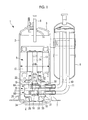
- a longitudinal sectional view of a multi-cylinder rotary compressor according to an embodiment of the present invention is shown
- a cross-sectional view showing the specifications of a compression mechanism section thereof is shown
- a longitudinal sectional view showing the specifications of the compression mechanism section is shown.
- a multi-cylinder rotary compressor 1 is a sealed type multi-cylinder rotary compressor 1 which is provided with a cylindrical sealed container 2 in which an upper portion and a lower portion are hermetically sealed by an upper cover 3 and a lower cover 4, a motor 5 is installed at a higher part in the inside thereof, and a compression mechanism (a rotary compressor mechanism) 6 which is driven by the motor 5 is installed at a lower part thereof.
- a mounting leg 7 is provided at the outer periphery of the lower portion of the sealed container 2. Further, a discharge pipe 8 penetrating the upper cover 3 is provided in the upper portion of the sealed container 2, and thus a configuration is made in which high-pressure refrigerant gas compressed in the multi-cylinder rotary compressor 1 is discharged to the refrigeration cycle side.
- an accumulator 9 is integrally assembled to an outer peripheral portion of the sealed container 2, and thus a configuration is made in which a liquid component such as oil or a liquid refrigerant which is contained in low-pressure refrigerant gas which returns from the refrigeration cycle side is separated out and only a gaseous component is sucked into the compression mechanism 6 through suction pipes 10 and 11.
- the motor 5 is provided with a stator 12 and a rotor 13, and the stator 12 is installed by being fixed to the inner peripheral surface of the sealed container 2 by press fitting or the like.
- a crankshaft 14 is integrally coupled to the rotor 13, whereby a rotational driving force of the rotor 13 can be transmitted to the compression mechanism 6 through the crankshaft 14.
- a first eccentric portion 15 and a second eccentric portion 16 are provided corresponding to a first rotor 24 and a second rotor 25 of the rotary compression mechanism 6 which will be described later.
- the rotary compression mechanism 6 is of, in this embodiment, a two-cylinder type.
- First and second rotary compression mechanisms 6A and 6B thereof are provided with a first cylinder main body 19 and a second cylinder main body 20 which have a first cylinder chamber 17 and a second cylinder chamber 18 (there is also a case of being hereinafter referred to simply as cylinders 17 and 18) formed therein and are fixedly installed in the sealed container 2 to correspond to the first eccentric portion 15 and the second eccentric portion 16 of the crankshaft 14, a partition plate (a separator plate) 21 which is interposed between the first cylinder main body 19 and the second cylinder main body 20, thereby separating the first cylinder chamber 17 and the second cylinder chamber 18, an upper bearing 22 which is provided on the upper surface of the first cylinder main body 19, thereby defining the first cylinder chamber 17 and supporting the crankshaft 14, and a lower bearing 23 which is provided on the lower surface of the second cylinder main body 20, thereby defining the second cylinder chamber 18 and supporting the crankshaft 14.
- first and second rotary compression mechanisms 6A and 6B are provided with the first rotor 24 and the second rotor 25 which are rotatably fitted to the first eccentric portion 15 and the second eccentric portion 16 and are rotated in the first cylinder chamber 17 and the second cylinder chamber 18, and blades 28 and 29 (refer to Fig. 2 ) which are slidably fitted into blade grooves 26 and 27 (refer to Fig. 2 ) provided in the first cylinder main body 19 and the second cylinder main body 20 and partition the insides of the first cylinder chamber 17 and the second cylinder chamber 18 into intake chamber sides and discharge chamber sides.
- a configuration is made such that the low-pressure refrigerant gas is sucked from the suction pipes 10 and 11 into the first cylinder chamber 17 and the second cylinder chamber 18 of the first and second rotary compression mechanisms 6A and 6B through suction ports 30 and 31, is compressed by the rotation of the first rotor 24 and the second rotor 25, thereafter, is discharged into discharge chambers 32 and 33 through discharge ports and discharge valves (not shown), is discharged from the discharge chambers 32 and 33 into the sealed container 2, and thereafter, is sent out to the refrigeration cycle through the discharge pipe 8.
- the first cylinder main body 19 and the second cylinder main body 20, the partition plate 21, the upper bearing 22, and the lower bearing 23 configuring the rotary compression mechanism 6 are integrally fastened and fixed to each other through bolts.
- refrigerant oil 34 such as PAG oil or POE oil is filled in a bottom portion in the sealed container 2 and can be fed to lubrication sites in the compression mechanism 6, as is known, through an oil feed hole or the like provided in the crankshaft 14.
- An extreme pressure agent adapted to each of the oils is added to the refrigerant oil 34 in an appropriate amount.
- the multi-cylinder rotary compressor 1 in order to increase a displacement (capacity) thereof to a capacity one level higher by increasing the internal diameter of each of the first cylinder chamber 17 and the second cylinder chamber 18, that is, a cylinder internal diameter ⁇ Dc, without changing a core diameter (a shell diameter or an eternal diameter) ⁇ Mo of the motor 5 which is already used in a compressor in production, when a motor core diameter is set to be ⁇ Mo and the cylinder internal diameter of each of the first cylinder chamber 17 and the second cylinder chamber 18 is set to be ⁇ Dc, the cylinder internal diameter ⁇ Dc is set so as to satisfy the relationship of ⁇ Dc/ ⁇ Mo ⁇ 0.49.
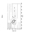
- ⁇ Dc/ ⁇ Mo which is the ratio between the motor core diameter ⁇ Mo and the cylinder internal diameter ⁇ Dc generally mostly falls within a range of 0.35 to 0.45 and is 0.48 at a maximum, as shown in Fig. 6 .
- a gas load a compression load
- ⁇ Dc/ ⁇ Mo forms a rightward and downward-sloping curve in a case where displacement is constant, as shown in Fig.
- a blade stroke (a sliding stroke of each of the blades 28 and 29) is made to be a longer stroke by increasing the cylinder internal diameter ⁇ Dc without changing the motor core diameter ⁇ Mo, thereby making ⁇ Dc/ ⁇ Mo which is the ratio therebetween be 0.49 or more
- the gas load (the compression load) which is determined from a frontal projected area of a rotor, which is the product of a rotor external diameter ⁇ Dr and a rotor width Hr, is restricted to a predetermined value or less with the frontal projected area of a rotor restricted.
- the displacement can be made to have a larger capacity by increasing the cylinder internal diameter ⁇ Dc without changing the motor core diameter ⁇ Mo was obtained. That is, if the displacement is made to have a larger capacity, as shown in Fig. 3 , the gas load which is the mechanical load increases, and thus the deformation amount of the crankshaft 14 increases, and therefore, it becomes necessary to suppress the deformation of the crankshaft 14. If the deformation amount of the crankshaft 14 increases, the degree of partial contact of the shaft with the bearing increases, and thus bearing surface pressure increases. The deformation amount of the crankshaft 14 depends on a distance between bearing support points L between the upper bearing 22 and the lower bearing 23, and therefore, it is found that making the distance between bearing support points L as small as possible is effective in suppressing the bearing surface pressure.
- the rotary compressor 1 having a displacement one level higher by using an existing facility without new capital investment, with the core diameter ⁇ Mo of the motor 5 being the existing core diameter ⁇ Mo in a hatching area shown in Fig. 6 .
- the partition plate 21 is configured with a material having a Young's modulus of 160 [GPa] or more, and it is favorable if, for example, carbon steel or alloy steel having a Young's modulus of about 200 [GPa] is used.
- the stroke of each of the blades 28 and 29 is increased according to this, thereby having to become a longer stroke, and due to the blade stroke becoming a longer stroke, pressure which is applied to the side surface of each of the blades 28 and 29 increases, and thus so-called blade side surface pressure rises.
- a hard coating such as a PVD film (a Physical Vapor Deposition film) of CrN type or the like or a DLC film (a DiamondLike Carbon film), for example, to both side surfaces of each of the blades 28 and 29 so as to be able to cope with abnormal wear or the like due to a surface pressure rise.
- the core diameter ⁇ Mo of the motor 5 is restricted by a manufacturing facility, and therefore, if the motor core diameter ⁇ Mo is increased, new capital investment is required.
- an increase in capacity is performed by increasing the cylinder internal diameter ⁇ Dc with the core diameter ⁇ Mo of the motor 5 set to be that in the existing rotary compressor 1, it is possible to manufacture the rotary compressor 1 having a displacement one level higher by using the existing facility without performing capital investment.
- the compression mechanism 6 includes the rotary compression mechanisms 6A and 6B provided with the plurality of cylinders 17 and 18, the partition plate 21 which separates the plurality of cylinders 17 and 18, the blades 28 and 29, each of which partitions the inside of each of the cylinders 17 and 18 into an intake side and a discharge side, and the rotors 24 and 25 which respectively rotate in the cylinders 17 and 18, a configuration is made in which when the core diameter of the motor 5 is set to be ⁇ Mo, the internal diameter of each of the cylinders 17 and 18 is set to be ⁇ Dc, the width of each of the cylinders 17 and 18 is set to Hc, and the width of the partition plate 21 is set to Hs, the relationship of Hs/Hc ⁇ 0.35 is satisfied under a condition of ⁇ Dc/ ⁇ Mo ⁇ 0.49.
- the displacement of the multi-cylinder rotary compressor 1 has a larger capacity (an increased displacement) by making the stroke of each of the blades 28 and 29 be a longer stroke without changing the motor core diameter ⁇ Mo and without increasing the gas load (the compression load), and it is possible to suppress a rise in bearing surface pressure by reducing the distance L between support points of the upper bearing 22 and the lower bearing 23 by making the width Hs of the partition plate as small as possible with respect to the cylinder width Hc. Therefore, it is possible to manufacture the sealed type multi-cylinder rotary compressor 1 having a displacement one level higher with the existing motor core diameter ⁇ Mo maintained, and thus it is possible to attain the expansion of a product lineup without performing great capital investment.
- the partition plate 21 is configured with a material such as carbon steel or alloy steel, for example, having a Young's modulus of 160 [GPa] or more, whereby even if the width Hs of the partition plate 21 is reduced to 0.35 or less of the cylinder width Hc, it is possible to suppress the deformation of the partition plate 21. Therefore, it is possible to suppress an increase of mechanical load such as bearing surface pressure, and thus it is possible to easily increase the displacement of the multi-cylinder rotary compressor 1 to a capacity one level higher by increasing the cylinder internal diameter ⁇ Dc without changing the motor core diameter ⁇ Mo.
- capacity is increased by increasing the cylinder internal diameter ⁇ Dc, whereby the stroke of each of the blades 28 and 29 is made to be a longer stroke, and thus the blade side surface pressure rises.
- the hard coating such as the PVD film of CrN type or the like or the DLC film is applied to the blade surface, whereby it is also possible to sufficiently cope with abnormal wear or the like due to a rise in blade side surface pressure. For this reason, it is possible to easily increase the displacement of the multi-cylinder rotary compressor 1 to a capacity one level higher without performing capital investment, by increasing the cylinder internal diameter ⁇ Dc without changing the core diameter ⁇ Mo of the motor 5.
- the extreme pressure agent is added to the refrigerant oil 34 which is filled into the bottom portion of the sealed container 2, although some increase of the mechanical load such as the bearing surface pressure or the blade side surface pressure according to an increase in the capacity of the compressor is inevitable and it becomes easy for an extreme pressure lubrication state to occur in the sliding portions, the extreme pressure agent which is effective under a high load is added to the refrigerant oil, whereby it is possible to maintain high lubricity on a sliding surface, thereby preventing seizure, wear, or scuffing. Accordingly, it is also possible to effectively cope with an increase in mechanical load according to an increase in the capacity of the rotary compressor 1.
- the present invention is not limited to an invention related to the above-described embodiment and modifications can be appropriately made within a scope which does not depart from the gist thereof.
- the first rotary compression mechanism 6A and the second rotary compression mechanism 6B may be provided with phases shifted by 180 degrees from each other.
- the discharge chambers 32 and 33 may be configured such that high-pressure gas discharged to the discharge chamber 33 joins in the discharge chamber 32 and is then discharged into the sealed container 2.
- the widths Hc of the first cylinder chamber 17 and the second cylinder chamber 18 need not necessarily be the same and may be different widths, and in this case, it is favorable if the cylinder chamber a larger width Hc is used as a reference.
Landscapes
- Engineering & Computer Science (AREA)
- Mechanical Engineering (AREA)
- General Engineering & Computer Science (AREA)
- Applications Or Details Of Rotary Compressors (AREA)
Abstract
Description
- The present invention relates to a sealed type multi-cylinder rotary compressor in which it is possible to increase the capacity (the displacement) of the compressor without increasing a motor core diameter.
- In a case of increasing the capacity of a sealed type rotary compressor, usually, a mechanical load such as bearing surface pressure or blade side surface pressure simply increases, and therefore, coping with this is performed by increasing a motor core diameter (shell diameter) or a journal diameter by one level by using a proportional design. However, an increase of the motor core diameter (shell diameter) or the journal diameter is restricted by a manufacturing facility, and therefore, design is performed by selection from a limited lineup. However, in a case of not having a compressor having a motor core diameter (shell diameter) one level higher, great capital investment is required.
- Therefore,
PTL 1 discloses a technique of allowing the displacement (the capacity) of a compressor to be made to have a larger capacity without changing a motor core diameter, in other words, without changing the external dimensions of the compressor. This is a technique in which in a sealed type multi-cylinder rotary compressor, a crankshaft is made to have a structure in which a plurality of portions are connected, whereby an increase in capacity is performed by reducing an opening provided in a partition plate separating a plurality of cylinders, providing a bearing for supporting a connection portion in the opening portion, accordingly reducing the external diameters of rotors rotating in the cylinders, and increasing the eccentricity of an eccentric shaft portion (making a blade stroke be a longer stroke), thereby increasing the effective capacity (displacement) in the cylinders. - [PTL 1] Japanese Patent No.
4365729 - However, in the technique disclosed in
PTL 1 described above, a structure in which the crankshaft is separated into a plurality of portions and the portions are then assembled has to be made, and therefore, the number of parts increases, and thus there is a problem such as the number of processing steps or the number of assembly steps increasing and complication of a configuration or higher cost being inevitable. - On the other hand, it is conceivable that a compressor having a displacement one level higher could be manufactured by making a blade stroke be a longer stroke by increasing the internal diameter of a cylinder, as a method of increasing capacity (displacement) without changing a motor core diameter. However, in this case, as described above, a mechanical load such as bearing surface pressure or a blade side surface pressure increases, and therefore, there is a technical problem such as measures to suppress an increase in the mechanical load becoming essential.
- The present invention has been made in view of such circumstances and has an object to provide a sealed type multi-cylinder rotary compressor in which it is possible to manufacture a compressor having a displacement one level higher by suppressing a mechanical load even if an increase in capacity is performed by increasing a cylinder internal diameter with the existing motor core diameter maintained, without increasing a motor core diameter.
- In order to solve the above-described problems, a multi-cylinder rotary compressor according to the present invention adopts the following means.
- According to a first aspect of the present invention, there is provided a multi-cylinder rotary compressor including: a motor provided in a sealed container; and a compression mechanism which is provided in the sealed container and driven by the motor, in which the compression mechanism is a rotary compression mechanism provided with a plurality of cylinders, a partition plate which separates the plurality of cylinders, a blade which partitions the inside of each of the cylinders into an intake side and a discharge side, and a rotor which rotates in each of the cylinders, and when a core diameter of the motor is set to be φMo, an internal diameter of each of the cylinders is set to be φDc, a width of each of the cylinders is set to Hc, and a width of the partition plate is set to Hs, the relationship of Hs/Hc≤0.35 is satisfied under a condition of φDc/φMo≥0.49.
- According to the first aspect of the present invention, in the sealed type multi-cylinder rotary compressor, it is possible to make the displacement of the compressor have a larger capacity (an increased displacement) by making a blade stroke be a longer stroke without changing the motor core diameter φMo and without much increasing a gas load (a compression load), by making the ratio of the width Hs of the partition plate to the width Hc of each cylinder be set to be 0.35 or less under a condition in which the ratio of the internal diameter φDc of each cylinder to the core diameter φMo of the motor is set to be 0.49 or more, and it is possible to suppress a rise in bearing surface pressure by reducing a distance between support points of an upper bearing and a lower bearing by making the width Hs of the partition plate as small as possible with respect to the width Hc of the cylinder. Therefore, it is possible to manufacture a sealed type multi-cylinder rotary compressor having a displacement one level higher with the existing motor core diameter maintained, and thus it is possible to attain the expansion of a product lineup without performing great capital investment.
- In the multi-cylinder rotary compressor according to a second aspect of the present invention, the partition plate is made of a material having a Young's modulus of 160 [GPa] or more.
- According to the second aspect of the present invention, the partition plate is configured with a material having a Young's modulus of 160 [GPa] or more, and therefore, even if the width Hs of the partition plate is reduced to 0.35 or less of the cylinder width Hc, by using a material having a Young's modulus of 160 [GPa] or more which is high compared to a sintered alloy or cast iron having a Young's modulus of 160 [GPa] or less, it is possible to reduce the distance between support points of the bearings while suppressing the deformation of the partition plate. Therefore, it is possible to suppress an increase of a mechanical load such as bearing surface pressure, and thus it is possible to easily increase the displacement of the compressor to a capacity one level higher without changing the motor core diameter.
- In the multi-cylinder rotary compressor according to a third aspect of the present invention, the partition plate is made of carbon steel or alloy steel.
- According to the third aspect of the present invention, the partition plate is made of carbon steel or alloy steel having a Young's modulus of 160 [GPa] or more, and therefore, by using carbon steel or alloy steel having higher rigidity than a sintered alloy or cast iron, it is possible to secure a Young's modulus of 160 [GPa] or more and suppress deformation while reducing the width of the partition plate simply by the selection of an appropriate material. Therefore, it is possible to suppress an increase of a mechanical load such as bearing surface pressure, and thus it is possible to easily increase the displacement of the compressor to a capacity one level higher without changing the motor core diameter.
- In the multi-cylinder rotary compressor according to a fourth aspect of the present invention, the blade is a blade with a hard coating such as a PVD film of CrN type or the like or a DLC film applied to the surface thereof.
- According to the fourth aspect of the present invention, the blade is a blade with a hard coating such as a PVD film of CrN type or the like or a DLC film applied to the surface thereof, and therefore, although blade side surface pressure rises due to an increase in a blade stroke, the hard coating is applied to the blade surface, whereby it is also possible to sufficiently cope with abnormal wear or the like due to a rise in surface pressure. Therefore, it is possible to easily increase the displacement of the compressor to a capacity one level higher without performing capital investment, by increasing the cylinder internal diameter without changing the motor core diameter.
- In the multi-cylinder rotary compressor according to a fifth aspect of the present invention, refrigerant oil which is filled into a bottom portion in the sealed container is refrigerant oil with an extreme pressure agent added thereto.
- According to the fifth aspect of the present invention, the refrigerant oil which is filled into the bottom portion in the sealed container is refrigerant oil with an extreme pressure agent added thereto, and therefore, although some increase of the mechanical load such as the bearing surface pressure or the blade side surface pressure according to an increase in the capacity of the compressor is inevitable and it becomes easy for an extreme pressure lubrication state to occur in the sliding portions, the extreme pressure agent which is effective under a high load is added to the refrigerant oil, whereby it is possible to maintain high lubricity on a sliding surface, thereby preventing seizure, wear, or scuffing. Therefore, it is also possible to effectively cope with an increase of a mechanical load according to an increase in the capacity of the compressor.
- According to the present invention, it is possible to make the displacement of the compressor have a larger capacity (an increased displacement) by making the blade stroke be a longer stroke without changing the motor core diameter φMo and without much increasing the gas load (the compression load), and it is possible to suppress a rise in bearing surface pressure by reducing the distance between support points of the upper bearing and the lower bearing by making the width Hs of the partition plate as small as possible with respect to the width Hc of the cylinder. For this reason, it is possible to manufacture a sealed type multi-cylinder rotary compressor having a displacement one level higher with the existing motor core diameter maintained, and thus it is possible to attain the expansion of a product lineup without performing great capital investment.
-
-
Fig. 1 is a longitudinal sectional view of a multi-cylinder rotary compressor according to an embodiment of the present invention. -
Fig. 2 is a cross-sectional view showing the specifications of a compression mechanism section of the multi-cylinder rotary compressor. -
Fig. 3 is a longitudinal sectional view showing the specifications of the compression mechanism section of the multi-cylinder rotary compressor. -
Fig. 4 is a graph showing the relationship between the ratio between a motor core diameter and a cylinder internal diameter of the multi-cylinder rotary compressor and a gas load. -
Fig. 5 is a graph showing the relationship between the ratio between a partition plate width and a cylinder width of the multi-cylinder rotary compressor and bearing surface pressure. -
Fig. 6 is a graph showing the relationship between the ratio between the partition plate width and the cylinder width of the multi-cylinder rotary compressor and the ratio between the motor core diameter and the cylinder internal diameter. - Hereinafter, an embodiment of the present invention will be described with reference to
Figs. 1 to 6 . - In
Fig. 1 , a longitudinal sectional view of a multi-cylinder rotary compressor according to an embodiment of the present invention is shown, and inFig. 2 , a cross-sectional view showing the specifications of a compression mechanism section thereof is shown, and inFig. 3 , a longitudinal sectional view showing the specifications of the compression mechanism section is shown. - A multi-cylinder
rotary compressor 1 according to this embodiment is a sealed type multi-cylinderrotary compressor 1 which is provided with a cylindrical sealedcontainer 2 in which an upper portion and a lower portion are hermetically sealed by anupper cover 3 and alower cover 4, amotor 5 is installed at a higher part in the inside thereof, and a compression mechanism (a rotary compressor mechanism) 6 which is driven by themotor 5 is installed at a lower part thereof. - A
mounting leg 7 is provided at the outer periphery of the lower portion of the sealedcontainer 2. Further, adischarge pipe 8 penetrating theupper cover 3 is provided in the upper portion of the sealedcontainer 2, and thus a configuration is made in which high-pressure refrigerant gas compressed in the multi-cylinderrotary compressor 1 is discharged to the refrigeration cycle side. In addition, anaccumulator 9 is integrally assembled to an outer peripheral portion of the sealedcontainer 2, and thus a configuration is made in which a liquid component such as oil or a liquid refrigerant which is contained in low-pressure refrigerant gas which returns from the refrigeration cycle side is separated out and only a gaseous component is sucked into thecompression mechanism 6 throughsuction pipes - The
motor 5 is provided with astator 12 and arotor 13, and thestator 12 is installed by being fixed to the inner peripheral surface of the sealedcontainer 2 by press fitting or the like. Acrankshaft 14 is integrally coupled to therotor 13, whereby a rotational driving force of therotor 13 can be transmitted to thecompression mechanism 6 through thecrankshaft 14. Further, at a lower part of thecrankshaft 14, a firsteccentric portion 15 and a secondeccentric portion 16 are provided corresponding to afirst rotor 24 and asecond rotor 25 of therotary compression mechanism 6 which will be described later. - The
rotary compression mechanism 6 is of, in this embodiment, a two-cylinder type. First and secondrotary compression mechanisms main body 19 and a second cylindermain body 20 which have afirst cylinder chamber 17 and a second cylinder chamber 18 (there is also a case of being hereinafter referred to simply ascylinders 17 and 18) formed therein and are fixedly installed in the sealedcontainer 2 to correspond to the firsteccentric portion 15 and the secondeccentric portion 16 of thecrankshaft 14, a partition plate (a separator plate) 21 which is interposed between the first cylindermain body 19 and the second cylindermain body 20, thereby separating thefirst cylinder chamber 17 and thesecond cylinder chamber 18, anupper bearing 22 which is provided on the upper surface of the first cylindermain body 19, thereby defining thefirst cylinder chamber 17 and supporting thecrankshaft 14, and alower bearing 23 which is provided on the lower surface of the second cylindermain body 20, thereby defining thesecond cylinder chamber 18 and supporting thecrankshaft 14. - Further, the first and second
rotary compression mechanisms first rotor 24 and thesecond rotor 25 which are rotatably fitted to the firsteccentric portion 15 and the secondeccentric portion 16 and are rotated in thefirst cylinder chamber 17 and thesecond cylinder chamber 18, and blades 28 and 29 (refer toFig. 2 ) which are slidably fitted into blade grooves 26 and 27 (refer toFig. 2 ) provided in the first cylindermain body 19 and the second cylindermain body 20 and partition the insides of thefirst cylinder chamber 17 and thesecond cylinder chamber 18 into intake chamber sides and discharge chamber sides. - A configuration is made such that the low-pressure refrigerant gas is sucked from the
suction pipes first cylinder chamber 17 and thesecond cylinder chamber 18 of the first and secondrotary compression mechanisms suction ports first rotor 24 and thesecond rotor 25, thereafter, is discharged intodischarge chambers discharge chambers container 2, and thereafter, is sent out to the refrigeration cycle through thedischarge pipe 8. - The first cylinder
main body 19 and the second cylindermain body 20, thepartition plate 21, the upper bearing 22, and thelower bearing 23 configuring therotary compression mechanism 6 are integrally fastened and fixed to each other through bolts. Further,refrigerant oil 34 such as PAG oil or POE oil is filled in a bottom portion in the sealedcontainer 2 and can be fed to lubrication sites in thecompression mechanism 6, as is known, through an oil feed hole or the like provided in thecrankshaft 14. An extreme pressure agent adapted to each of the oils is added to therefrigerant oil 34 in an appropriate amount. - In the multi-cylinder
rotary compressor 1 described above, in order to increase a displacement (capacity) thereof to a capacity one level higher by increasing the internal diameter of each of thefirst cylinder chamber 17 and thesecond cylinder chamber 18, that is, a cylinder internal diameter φDc, without changing a core diameter (a shell diameter or an eternal diameter) φMo of themotor 5 which is already used in a compressor in production, when a motor core diameter is set to be φMo and the cylinder internal diameter of each of thefirst cylinder chamber 17 and thesecond cylinder chamber 18 is set to be φDc, the cylinder internal diameter φDc is set so as to satisfy the relationship of φDc/φMo≥0.49. - This is because in a rotary compressor during production in a current situation, φDc/φMo which is the ratio between the motor core diameter φMo and the cylinder internal diameter φDc generally mostly falls within a range of 0.35 to 0.45 and is 0.48 at a maximum, as shown in
Fig. 6 . On the other hand, the relationship between a gas load (a compression load) which becomes a mechanical load of a rotary compressor and φDc/φMo forms a rightward and downward-sloping curve in a case where displacement is constant, as shown inFig. 4 , and for this reason, it is found that even if the value of φDc/φMo is increased by increasing the cylinder internal diameter φDc, the gas load (refer toFig. 3 ) does not increase and the mechanical load does not increase. - That is, it is apparent from
Figs. 4 and6 that even if in order to increase the displacement of therotary compressor 1 to a certain value, a blade stroke (a sliding stroke of each of the blades 28 and 29) is made to be a longer stroke by increasing the cylinder internal diameter φDc without changing the motor core diameter φMo, thereby making φDc/φMo which is the ratio therebetween be 0.49 or more, the gas load (the compression load) which is determined from a frontal projected area of a rotor, which is the product of a rotor external diameter φDr and a rotor width Hr, is restricted to a predetermined value or less with the frontal projected area of a rotor restricted. - Knowledge that if the gas load which determines the mechanical load can be restricted to a certain value or less under the above-described conditions, the displacement can be made to have a larger capacity by increasing the cylinder internal diameter φDc without changing the motor core diameter φMo was obtained. That is, if the displacement is made to have a larger capacity, as shown in
Fig. 3 , the gas load which is the mechanical load increases, and thus the deformation amount of thecrankshaft 14 increases, and therefore, it becomes necessary to suppress the deformation of thecrankshaft 14. If the deformation amount of thecrankshaft 14 increases, the degree of partial contact of the shaft with the bearing increases, and thus bearing surface pressure increases. The deformation amount of thecrankshaft 14 depends on a distance between bearing support points L between theupper bearing 22 and thelower bearing 23, and therefore, it is found that making the distance between bearing support points L as small as possible is effective in suppressing the bearing surface pressure. - In order to make the distance between bearing support points L small, it is favorable if a width Hc of each of the
first cylinder chamber 17 and the second cylinder chambers 18 (hereinafter referred to as a cylinder width Hc) and a width Hs of the partition plate (the separator plate) 21 (hereinafter referred to as a partition plate width Hs) are reduced. However, in increasing the displacement, it is difficult to reduce the cylinder width Hc. Therefore, the partition plate width Hs is reduced. However, as a result of the analysis of the relationship between the partition plate width Hs and the cylinder width Hc, and the bearing surface pressure, when a graph with Hs/Hc as the horizontal axis and the bearing surface pressure as the vertical axis is made, as shown inFig. 5 , an rightward and upward-sloping curve is obtained, and it is found that if Hs/Hc is set to be less than or equal to a predetermined value, it is possible to make the bearing surface pressure be less than or equal to an allowable value. - From the above, even if the relationship of φDc/φMo≥0.49 is satisfied by increasing the cylinder internal diameter φDc without changing the motor core diameter φMo affecting a manufacturing facility (the motor core diameter is restricted by a manufacturing facility, and thus if the motor core diameter is increased, new capital investment is required), if Hs/Hc is limited to the relationship of Hs/Hc≤0.35, it becomes possible to make the displacement of the
rotary compressor 1 have a larger capacity by suppressing an increase in the bearing surface pressure which is the mechanical load. That is, it becomes possible to easily manufacture therotary compressor 1 having a displacement one level higher by using an existing facility without new capital investment, with the core diameter φMo of themotor 5 being the existing core diameter φMo in a hatching area shown inFig. 6 . - In addition, as described above, if a partition plate made of sintered metal or cast iron which has been used for the
partition plate 21 in the past is used as it is by reducing the width Hs of thepartition plate 21, since these materials have a low Young's modulus of 160 [GPa] or less, there is a possibility that deformation due to a reduction in width may become a problem. Therefore, it is desirable that thepartition plate 21 is configured with a material having a Young's modulus of 160 [GPa] or more, and it is favorable if, for example, carbon steel or alloy steel having a Young's modulus of about 200 [GPa] is used. - Further, if the cylinder internal diameter φDc is increased, the stroke of each of the blades 28 and 29 is increased according to this, thereby having to become a longer stroke, and due to the blade stroke becoming a longer stroke, pressure which is applied to the side surface of each of the blades 28 and 29 increases, and thus so-called blade side surface pressure rises. In order to cope with this, it is desirable to apply a hard coating such as a PVD film (a Physical Vapor Deposition film) of CrN type or the like or a DLC film (a DiamondLike Carbon film), for example, to both side surfaces of each of the blades 28 and 29 so as to be able to cope with abnormal wear or the like due to a surface pressure rise.
- In addition, although an attempt to suppress an increase in the mechanical load due to making the displacement of the compressor have a larger capacity, as much as possible, is made, some increase of the mechanical load such as the bearing surface pressure or the blade side surface pressure is inevitable and it becomes easy for an extreme pressure lubrication state to occur in sliding portions such as the
bearings rotors refrigerant oil 34 filled in the bottom portion in the sealedcontainer 2, in an appropriate amount. - Due to the configuration described above, according to this embodiment, the following operation and effects are exhibited.
- In the
rotary compressor 1, if the internal diameter of each of thefirst cylinder chamber 17 and thesecond cylinder chamber 18, that is, the cylinder internal diameter φDc, is increased, a cylinder volume increases, and therefore, it is possible to make the displacement of the compressor have a larger capacity by increasing the eccentricities of the firsteccentric portion 15 and the secondeccentric portion 16, thereby increasing the strokes of the blades 28 and 29. - Further, when manufacturing the
rotary compressor 1, the core diameter φMo of themotor 5 is restricted by a manufacturing facility, and therefore, if the motor core diameter φMo is increased, new capital investment is required. However, if an increase in capacity is performed by increasing the cylinder internal diameter φDc with the core diameter φMo of themotor 5 set to be that in the existingrotary compressor 1, it is possible to manufacture therotary compressor 1 having a displacement one level higher by using the existing facility without performing capital investment. - Thus, in this embodiment, in the sealed type
multi-cylinder rotary compressor 1 in which themotor 5 and thecompression mechanism 6 which is driven by themotor 5 are provided in the sealedcontainer 2 and thecompression mechanism 6 includes therotary compression mechanisms cylinders partition plate 21 which separates the plurality ofcylinders cylinders rotors cylinders motor 5 is set to be φMo, the internal diameter of each of thecylinders cylinders partition plate 21 is set to Hs, the relationship of Hs/Hc≤0.35 is satisfied under a condition of φDc/φMo≥0.49. - In this way, it is possible to make the displacement of the multi-cylinder
rotary compressor 1 have a larger capacity (an increased displacement) by making the stroke of each of the blades 28 and 29 be a longer stroke without changing the motor core diameter φMo and without increasing the gas load (the compression load), and it is possible to suppress a rise in bearing surface pressure by reducing the distance L between support points of theupper bearing 22 and thelower bearing 23 by making the width Hs of the partition plate as small as possible with respect to the cylinder width Hc. Therefore, it is possible to manufacture the sealed typemulti-cylinder rotary compressor 1 having a displacement one level higher with the existing motor core diameter φMo maintained, and thus it is possible to attain the expansion of a product lineup without performing great capital investment. - Further, the possibility of the deformation of the
partition plate 21 arises due to reducing the width Hs of thepartition plate 21 so as to satisfy the relationship of Hs/Hc≤0.35. However, thepartition plate 21 is configured with a material such as carbon steel or alloy steel, for example, having a Young's modulus of 160 [GPa] or more, whereby even if the width Hs of thepartition plate 21 is reduced to 0.35 or less of the cylinder width Hc, it is possible to suppress the deformation of thepartition plate 21. Therefore, it is possible to suppress an increase of mechanical load such as bearing surface pressure, and thus it is possible to easily increase the displacement of the multi-cylinderrotary compressor 1 to a capacity one level higher by increasing the cylinder internal diameter φDc without changing the motor core diameter φMo. - In addition, capacity is increased by increasing the cylinder internal diameter φDc, whereby the stroke of each of the blades 28 and 29 is made to be a longer stroke, and thus the blade side surface pressure rises. However, the hard coating such as the PVD film of CrN type or the like or the DLC film is applied to the blade surface, whereby it is also possible to sufficiently cope with abnormal wear or the like due to a rise in blade side surface pressure. For this reason, it is possible to easily increase the displacement of the multi-cylinder
rotary compressor 1 to a capacity one level higher without performing capital investment, by increasing the cylinder internal diameter φDc without changing the core diameter φMo of themotor 5. - Further, since the extreme pressure agent is added to the
refrigerant oil 34 which is filled into the bottom portion of the sealedcontainer 2, although some increase of the mechanical load such as the bearing surface pressure or the blade side surface pressure according to an increase in the capacity of the compressor is inevitable and it becomes easy for an extreme pressure lubrication state to occur in the sliding portions, the extreme pressure agent which is effective under a high load is added to the refrigerant oil, whereby it is possible to maintain high lubricity on a sliding surface, thereby preventing seizure, wear, or scuffing. Accordingly, it is also possible to effectively cope with an increase in mechanical load according to an increase in the capacity of therotary compressor 1. - In addition, the present invention is not limited to an invention related to the above-described embodiment and modifications can be appropriately made within a scope which does not depart from the gist thereof. For example, it goes without saying that in the above-described embodiment, the first
rotary compression mechanism 6A and the secondrotary compression mechanism 6B may be provided with phases shifted by 180 degrees from each other. Further, of course, thedischarge chambers discharge chamber 33 joins in thedischarge chamber 32 and is then discharged into the sealedcontainer 2. In addition, the widths Hc of thefirst cylinder chamber 17 and thesecond cylinder chamber 18 need not necessarily be the same and may be different widths, and in this case, it is favorable if the cylinder chamber a larger width Hc is used as a reference. -
- 1:
- multi-cylinder rotary compressor
- 2:
- sealed container
- 5:
- motor
- 6:
- compression mechanism (rotary compression mechanism)
- 6A:
- first rotary compression mechanism
- 6B:
- second rotary compression mechanism
- 14:
- crankshaft
- 15:
- first eccentric portion
- 16:
- second eccentric portion
- 17:
- first cylinder chamber (cylinder)
- 18:
- second cylinder chamber (cylinder)
- 19:
- first cylinder main body
- 20:
- second cylinder main body
- 21:
- partition plate
- 24:
- first rotor
- 25:
- second rotor
- 28, 29:
- blade
- 34:
- refrigerant oil
- φMo:
- motor core diameter
- φDc:
- cylinder internal diameter
- Hc:
- cylinder width
- Hs:
- partition plate width
Claims (5)
- A multi-cylinder rotary compressor comprising:a motor provided in a sealed container; anda compression mechanism which is provided in the sealed container and driven by the motor,wherein the compression mechanism is a rotary compression mechanism provided with a plurality of cylinders, a partition plate which separates the plurality of cylinders, a blade which partitions the inside of each of the cylinders into an intake side and a discharge side, and a rotor which rotates in each of the cylinders, andwhen a core diameter of the motor is set to be φMo, an internal diameter of each of the cylinders is set to be φDc, a width of each of the cylinders is set to Hc, and a width of the partition plate is set to Hs, the relationship of Hs/Hc≤0.35 is satisfied under a condition of φDc/φMo≥0.49.
- The multi-cylinder rotary compressor according to Claim 1, wherein the partition plate is made of a material having a Young's modulus of 160 [GPa] or more.
- The multi-cylinder rotary compressor according to Claim 2, wherein the partition plate is made of carbon steel or alloy steel.
- The multi-cylinder rotary compressor according to any one of Claims 1 to 3, wherein the blade is a blade with a hard coating such as a PVD film of CrN type or the like or a DLC film applied to the surface thereof.
- The multi-cylinder rotary compressor according to any one of Claims 1 to 4, wherein refrigerant oil which is filled into a bottom portion in the sealed container is refrigerant oil with an extreme pressure agent added thereto.
Applications Claiming Priority (2)
| Application Number | Priority Date | Filing Date | Title |
|---|---|---|---|
| JP2013073093A JP2014196714A (en) | 2013-03-29 | 2013-03-29 | Multicylinder rotary compressor |
| PCT/JP2014/056650 WO2014156679A1 (en) | 2013-03-29 | 2014-03-13 | Multi-cylinder rotary compressor |
Publications (2)
| Publication Number | Publication Date |
|---|---|
| EP2947321A1 true EP2947321A1 (en) | 2015-11-25 |
| EP2947321A4 EP2947321A4 (en) | 2016-02-24 |
Family
ID=51623662
Family Applications (1)
| Application Number | Title | Priority Date | Filing Date |
|---|---|---|---|
| EP14774791.9A Withdrawn EP2947321A4 (en) | 2013-03-29 | 2014-03-13 | Multi-cylinder rotary compressor |
Country Status (4)
| Country | Link |
|---|---|
| EP (1) | EP2947321A4 (en) |
| JP (1) | JP2014196714A (en) |
| CN (1) | CN105008722A (en) |
| WO (1) | WO2014156679A1 (en) |
Families Citing this family (8)
| Publication number | Priority date | Publication date | Assignee | Title |
|---|---|---|---|---|
| CN105201845B (en) * | 2015-10-22 | 2017-11-07 | 广东美芝制冷设备有限公司 | Rotary compressor |
| WO2017138175A1 (en) * | 2016-02-12 | 2017-08-17 | 東芝キヤリア株式会社 | Rotary compressor and refrigeration cycle device |
| CN105840508A (en) * | 2016-05-17 | 2016-08-10 | 广东美芝制冷设备有限公司 | Rotary compressor and refrigeration circulation device comprising same |
| CN109958622B (en) * | 2017-12-25 | 2021-06-08 | 上海海立电器有限公司 | A rolling rotor compressor |
| CN108788658A (en) * | 2018-06-08 | 2018-11-13 | 宁波甬微集团有限公司 | The production method of partition board in a kind of multicylinder compressor |
| CN109083843A (en) * | 2018-07-22 | 2018-12-25 | 宁波甬微集团有限公司 | The production method of partition in a kind of multicylinder compressor |
| CN109113999A (en) * | 2018-09-06 | 2019-01-01 | 宁波甬微集团有限公司 | The production method of partition in a kind of multicylinder compressor |
| JP2026013916A (en) | 2024-07-18 | 2026-01-29 | ダイキン工業株式会社 | Rotary compressor and refrigeration device |
Family Cites Families (12)
| Publication number | Priority date | Publication date | Assignee | Title |
|---|---|---|---|---|
| JPS59165885A (en) * | 1983-03-09 | 1984-09-19 | Matsushita Refrig Co | Rotary compressor with multiple cylinders |
| JPS61126395A (en) * | 1984-11-22 | 1986-06-13 | Mitsubishi Electric Corp | 2-cylinder type rotary compressor |
| JPH03206387A (en) * | 1990-01-08 | 1991-09-09 | Hitachi Ltd | Rotary type compressor |
| JP2790515B2 (en) * | 1990-03-06 | 1998-08-27 | 松下冷機株式会社 | 2-cylinder rotary compressor |
| JPH06159277A (en) * | 1992-11-26 | 1994-06-07 | Sanyo Electric Co Ltd | Multi-cylinder rotary compressor |
| JPH109168A (en) * | 1996-06-28 | 1998-01-13 | Hitachi Ltd | Rotary compressor |
| JP2005257240A (en) * | 2004-03-15 | 2005-09-22 | Sanyo Electric Co Ltd | Transition critical refrigerating device |
| JP4365729B2 (en) | 2004-05-31 | 2009-11-18 | 三菱重工業株式会社 | Rotary compressor |
| JP4780971B2 (en) * | 2005-02-17 | 2011-09-28 | 三洋電機株式会社 | Rotary compressor |
| JP2008101523A (en) * | 2006-10-18 | 2008-05-01 | Daikin Ind Ltd | Hermetic compressor |
| WO2011148453A1 (en) * | 2010-05-24 | 2011-12-01 | 三菱電機株式会社 | Two-stage rotary compressor and heat pump apparatus |
| CN103097733A (en) * | 2010-09-07 | 2013-05-08 | 松下电器产业株式会社 | Compressor and refrigeration cycle device using same |
-
2013
- 2013-03-29 JP JP2013073093A patent/JP2014196714A/en active Pending
-
2014
- 2014-03-13 WO PCT/JP2014/056650 patent/WO2014156679A1/en not_active Ceased
- 2014-03-13 CN CN201480008720.0A patent/CN105008722A/en active Pending
- 2014-03-13 EP EP14774791.9A patent/EP2947321A4/en not_active Withdrawn
Also Published As
| Publication number | Publication date |
|---|---|
| WO2014156679A1 (en) | 2014-10-02 |
| EP2947321A4 (en) | 2016-02-24 |
| JP2014196714A (en) | 2014-10-16 |
| CN105008722A (en) | 2015-10-28 |
Similar Documents
| Publication | Publication Date | Title |
|---|---|---|
| JP4310960B2 (en) | Scroll type fluid machinery | |
| WO2014156679A1 (en) | Multi-cylinder rotary compressor | |
| EP3214263B1 (en) | Two-cylinder hermetic compressor | |
| JP5441982B2 (en) | Rotary compressor | |
| US9157437B2 (en) | Rotary compressor with oiling mechanism | |
| JPWO2009145232A1 (en) | Hermetic compressor and refrigeration cycle apparatus | |
| US20130171017A1 (en) | Rotary compressor with dual eccentric portion | |
| CN104976123A (en) | Multi-cylinder rotary compressor | |
| JP2017150425A (en) | Two-cylinder type sealed compressor | |
| JP5449999B2 (en) | Hermetic compressor and refrigeration cycle equipment | |
| EP2918773B1 (en) | Rotary compressor | |
| KR20110128674A (en) | Hermetic compressor | |
| JP2012149545A (en) | Rotary compressor | |
| JP2012047060A (en) | Compressor | |
| EP2942526A1 (en) | Rotary compressor | |
| US10309399B2 (en) | Rotary compressor | |
| CN205089618U (en) | Multi -cylinder rotary compressor | |
| EP3388675A1 (en) | Oscillating piston-type compressor | |
| JP2011174407A (en) | Scroll fluid machine | |
| WO2016151769A1 (en) | Hermetic rotary compressor | |
| JP6429987B2 (en) | Rotary compressor | |
| JP6643712B2 (en) | 2-cylinder hermetic compressor | |
| EP2514972A1 (en) | Fluid machinery | |
| JP2017008819A (en) | Rotary compressor | |
| JP2014202200A (en) | Rotary compressor |
Legal Events
| Date | Code | Title | Description |
|---|---|---|---|
| PUAI | Public reference made under article 153(3) epc to a published international application that has entered the european phase |
Free format text: ORIGINAL CODE: 0009012 |
|
| 17P | Request for examination filed |
Effective date: 20150812 |
|
| AK | Designated contracting states |
Kind code of ref document: A1 Designated state(s): AL AT BE BG CH CY CZ DE DK EE ES FI FR GB GR HR HU IE IS IT LI LT LU LV MC MK MT NL NO PL PT RO RS SE SI SK SM TR |
|
| AX | Request for extension of the european patent |
Extension state: BA ME |
|
| RIC1 | Information provided on ipc code assigned before grant |
Ipc: F04C 23/00 20060101AFI20160114BHEP Ipc: F01C 21/10 20060101ALI20160114BHEP Ipc: F04C 18/356 20060101ALI20160114BHEP Ipc: F04C 29/00 20060101ALI20160114BHEP |
|
| A4 | Supplementary search report drawn up and despatched |
Effective date: 20160122 |
|
| DAX | Request for extension of the european patent (deleted) | ||
| RAP1 | Party data changed (applicant data changed or rights of an application transferred) |
Owner name: MITSUBISHI HEAVY INDUSTRIES THERMAL SYSTEMS, LTD. |
|
| 17Q | First examination report despatched |
Effective date: 20190910 |
|
| STAA | Information on the status of an ep patent application or granted ep patent |
Free format text: STATUS: THE APPLICATION HAS BEEN WITHDRAWN |
|
| 18W | Application withdrawn |
Effective date: 20191028 |