EP2947249A1 - Device for opening and closing vehicle door - Google Patents
Device for opening and closing vehicle door Download PDFInfo
- Publication number
- EP2947249A1 EP2947249A1 EP14881425.4A EP14881425A EP2947249A1 EP 2947249 A1 EP2947249 A1 EP 2947249A1 EP 14881425 A EP14881425 A EP 14881425A EP 2947249 A1 EP2947249 A1 EP 2947249A1
- Authority
- EP
- European Patent Office
- Prior art keywords
- opening
- closing
- guide rail
- cable
- moving member
- Prior art date
- Legal status (The legal status is an assumption and is not a legal conclusion. Google has not performed a legal analysis and makes no representation as to the accuracy of the status listed.)
- Granted
Links
Images


Classifications
-
- E—FIXED CONSTRUCTIONS
- E05—LOCKS; KEYS; WINDOW OR DOOR FITTINGS; SAFES
- E05F—DEVICES FOR MOVING WINGS INTO OPEN OR CLOSED POSITION; CHECKS FOR WINGS; WING FITTINGS NOT OTHERWISE PROVIDED FOR, CONCERNED WITH THE FUNCTIONING OF THE WING
- E05F15/00—Power-operated mechanisms for wings
- E05F15/60—Power-operated mechanisms for wings using electrical actuators
- E05F15/603—Power-operated mechanisms for wings using electrical actuators using rotary electromotors
- E05F15/632—Power-operated mechanisms for wings using electrical actuators using rotary electromotors for horizontally-sliding wings
- E05F15/643—Power-operated mechanisms for wings using electrical actuators using rotary electromotors for horizontally-sliding wings operated by flexible elongated pulling elements, e.g. belts, chains or cables
-
- B—PERFORMING OPERATIONS; TRANSPORTING
- B60—VEHICLES IN GENERAL
- B60J—WINDOWS, WINDSCREENS, NON-FIXED ROOFS, DOORS, OR SIMILAR DEVICES FOR VEHICLES; REMOVABLE EXTERNAL PROTECTIVE COVERINGS SPECIALLY ADAPTED FOR VEHICLES
- B60J5/00—Doors
- B60J5/04—Doors arranged at the vehicle sides
- B60J5/047—Doors arranged at the vehicle sides characterised by the opening or closing movement
-
- B—PERFORMING OPERATIONS; TRANSPORTING
- B60—VEHICLES IN GENERAL
- B60J—WINDOWS, WINDSCREENS, NON-FIXED ROOFS, DOORS, OR SIMILAR DEVICES FOR VEHICLES; REMOVABLE EXTERNAL PROTECTIVE COVERINGS SPECIALLY ADAPTED FOR VEHICLES
- B60J5/00—Doors
- B60J5/04—Doors arranged at the vehicle sides
- B60J5/06—Doors arranged at the vehicle sides slidable; foldable
-
- E—FIXED CONSTRUCTIONS
- E05—LOCKS; KEYS; WINDOW OR DOOR FITTINGS; SAFES
- E05D—HINGES OR SUSPENSION DEVICES FOR DOORS, WINDOWS OR WINGS
- E05D15/00—Suspension arrangements for wings
- E05D15/06—Suspension arrangements for wings for wings sliding horizontally more or less in their own plane
- E05D15/0621—Details, e.g. suspension or supporting guides
-
- E—FIXED CONSTRUCTIONS
- E05—LOCKS; KEYS; WINDOW OR DOOR FITTINGS; SAFES
- E05F—DEVICES FOR MOVING WINGS INTO OPEN OR CLOSED POSITION; CHECKS FOR WINGS; WING FITTINGS NOT OTHERWISE PROVIDED FOR, CONCERNED WITH THE FUNCTIONING OF THE WING
- E05F15/00—Power-operated mechanisms for wings
- E05F15/60—Power-operated mechanisms for wings using electrical actuators
- E05F15/603—Power-operated mechanisms for wings using electrical actuators using rotary electromotors
- E05F15/632—Power-operated mechanisms for wings using electrical actuators using rotary electromotors for horizontally-sliding wings
- E05F15/643—Power-operated mechanisms for wings using electrical actuators using rotary electromotors for horizontally-sliding wings operated by flexible elongated pulling elements, e.g. belts, chains or cables
- E05F15/646—Power-operated mechanisms for wings using electrical actuators using rotary electromotors for horizontally-sliding wings operated by flexible elongated pulling elements, e.g. belts, chains or cables allowing or involving a secondary movement of the wing, e.g. rotational or transversal
-
- E—FIXED CONSTRUCTIONS
- E05—LOCKS; KEYS; WINDOW OR DOOR FITTINGS; SAFES
- E05Y—INDEXING SCHEME ASSOCIATED WITH SUBCLASSES E05D AND E05F, RELATING TO CONSTRUCTION ELEMENTS, ELECTRIC CONTROL, POWER SUPPLY, POWER SIGNAL OR TRANSMISSION, USER INTERFACES, MOUNTING OR COUPLING, DETAILS, ACCESSORIES, AUXILIARY OPERATIONS NOT OTHERWISE PROVIDED FOR, APPLICATION THEREOF
- E05Y2201/00—Constructional elements; Accessories therefor
- E05Y2201/40—Motors; Magnets; Springs; Weights; Accessories therefor
- E05Y2201/43—Motors
- E05Y2201/434—Electromotors; Details thereof
-
- E—FIXED CONSTRUCTIONS
- E05—LOCKS; KEYS; WINDOW OR DOOR FITTINGS; SAFES
- E05Y—INDEXING SCHEME ASSOCIATED WITH SUBCLASSES E05D AND E05F, RELATING TO CONSTRUCTION ELEMENTS, ELECTRIC CONTROL, POWER SUPPLY, POWER SIGNAL OR TRANSMISSION, USER INTERFACES, MOUNTING OR COUPLING, DETAILS, ACCESSORIES, AUXILIARY OPERATIONS NOT OTHERWISE PROVIDED FOR, APPLICATION THEREOF
- E05Y2201/00—Constructional elements; Accessories therefor
- E05Y2201/60—Suspension or transmission members; Accessories therefor
- E05Y2201/622—Suspension or transmission members elements
- E05Y2201/684—Rails; Tracks
-
- E—FIXED CONSTRUCTIONS
- E05—LOCKS; KEYS; WINDOW OR DOOR FITTINGS; SAFES
- E05Y—INDEXING SCHEME ASSOCIATED WITH SUBCLASSES E05D AND E05F, RELATING TO CONSTRUCTION ELEMENTS, ELECTRIC CONTROL, POWER SUPPLY, POWER SIGNAL OR TRANSMISSION, USER INTERFACES, MOUNTING OR COUPLING, DETAILS, ACCESSORIES, AUXILIARY OPERATIONS NOT OTHERWISE PROVIDED FOR, APPLICATION THEREOF
- E05Y2900/00—Application of doors, windows, wings or fittings thereof
- E05Y2900/50—Application of doors, windows, wings or fittings thereof for vehicles
- E05Y2900/53—Type of wing
- E05Y2900/531—Doors
Definitions
- the present invention relates to a vehicle door opening device for opening and closing a vehicle door electrically.
- a vehicle door opening device in Patent Literature 1 comprises a longitudinal guide rail fixed to the side of a vehicle body; a moving member that can move along the guide rail to open and close a sliding door; a door opening/closing drive unit (door drive in Patent Literature 1) comprising a motor; and an opening cable and a closing cable wound on and reeled off a rotary drum of the drive opening/closing drive unit.
- door drive in Patent Literature 1 door drive in Patent Literature 1
- Each of the cables reeled off the rotary drum is connected to a cable coupling portion of the moving member while each of the cables is wound around each reversible pulley, whereby power of the motor is transmitted to the moving member via the opening cable or closing cable to enable the sliding door to open or close.
- Patent Literature 1 JP8-232538A
- the end of each of the cables is coupled to the cable coupling portion of the moving member such that the ends of the cables face each other, thereby increasing the width of the moving member along a moving direction.
- the width of the moving member is increased to affect stroke of the moving member and opening/closing stroke of the sliding door.
- a coil spring for taking up the slack in each of the cables is disposed in the cable coupling portion, thereby further increasing the width of the moving member and greatly affecting the opening/closing stroke of the sliding door.
- the first invention provides a vehicle door opening device in which a door is supported on a vehicle body to open and close by a motor, the device comprising:
- the second invention provides the vehicle door opening device in the first invention, wherein the closing reversible member is disposed under the lower surface at one end of the guide rail; the opening reversible member is disposed on the upper surface at the other end of the guide rail; the closing coupling portion is provided on a lower part of the moving member; the opening coupling portion is provided on an upper part of the moving member; the closing cable moves along the lower surface of the center guide rail; and the closing cable moves along the upper surface of the center guide rail.
- the third invention provides the vehicle door opening device in the first or second invention, wherein the closing coupling portion and the opening coupling portion have a tensioner for giving tension to the closing cable and the opening cable respectively.
- the closing coupling portion and the opening coupling portion are spaced from each other in the direction perpendicular to the moving direction of the moving member, thereby reducing width of the moving member along the moving direction and increasing stroke of the moving member.
- FIG. 1 and the bottom in FIG. 2 are deemed as the front of a vehicle, and the right in FIG. 1 and the top in FIG. 2 are deemed as the back of the vehicle.
- a sliding door in the vehicle is supported by an upper guide rail 1, a center guide rail 2 and a lower guide rail 3 fixed to the side of a vehicle body B and can slide longitudinally of the vehicle by electric force of a door-opening drive unit 4 (later described) mounted to the side of the vehicle body B from a fully-closed position where an entrance at the side of the vehicle body B closes to a fully-open position where the door moves backward along the side of the vehicle body B or the center guide rail 2 while the door slightly moves outward from the side of the vehicle body and vice versa.
- the top of the center guide rail 2 is covered with a finisher B2 fixed to the vehicle body B.
- FIG. 2 in a panel P that forms the side of the vehicle body B, there is formed a rectangular opening P1 through which a driven portion 41 (later described) of the door-opening drive unit 4 can be introduced from the outside to the inside of the panel P.
- the opening P1 is formed in such size that the driven portion 41 of the door-opening drive unit 4 can be introduced from the outside to the inside.
- the driven portion 41 of the door-opening drive unit 4 can be attached from the outside of the vehicle, and a drive portion 42 (later described) of the door-opening drive unit 4 can be attached from the inside of the vehicle.
- the center guide rail 2 has a vertical cross-section like a channel and is fixed along a longitudinal direction of the vehicle.
- a front reversible pulley 5 as a reversible closing member on which a closing cable 10 (later described) comprising a Bowden cable is wound is rotatably mounted via a vertical shaft 6, and on the upper surface of the rear of the center guide rail 2 extending backward straight, a reversible rear pulley 7 as a reversible opening member on which an opening cable 11 (later described) comprising a Bowden cable is wound is rotatably mounted via a vertical shaft 8.
- a lower arcuate guide member 22 for guiding the closing cable 10 longitudinally in sliding contact therewith is fixed, and on the upper part, an upper arcuate guide member 23 for guiding the opening cable 11 longitudinally in sliding contact therewith is fixed.
- the door D is connected to moving members (not shown) which move along the upper guide rail 1 and lower guide rail 3 longitudinally and to a moving member 9 which moves along the center guide rail 2 longitudinally and is supported on the vehicle body B to open and close longitudinally.
- a roller 93 is rotatably mounted around a vertical shaft, and a roller 94 is rotatably mounted around a horizontal shaft.
- the rollers 93, 94 roll in the center guide rail 2. So the moving member 9 can move along the center guide rail 2 between a fully-open position 9A at the front end of the center guide rail 2 and a fully-closed position at the rear end as shown by two-dotted lines in FIG. 6 .
- a tubular closing coupling portion 91 coupled to the rear end of the closing cable 10 which is wound on the front reversible pulley 5 and extends backward.
- a tubular opening coupling portion 92 connected to the front end of the opening cable 11 which is wound around the rear reversible pulley 7 and extends forward. The closing coupling portion 91 and opening coupling portion 92 are spaced from each other perpendicular to a moving direction of the moving member 9.
- the closing coupling portion 91 and opening coupling portion 92 have tensioners 911 and 921 ( FIG. 8 ) respectively, each comprising a coil spring which applies tension to the closing cable 10 and opening cable 11 and takes up the slack of the cables 10, 11.
- the door opening drive unit 4 comprises the driven portion 41 mounted to the panel P and the drive portion 42 coupled to the driven portion 41.
- the driven portion 41 comprises an approximately cylindrical casing 411 fixed to the panel P with a bracket 21, and a rotary drum 412 which is rotatably mounted via a vertical shaft in the casing 411.
- the casing 411 is fixed to the bracket 21 with two bolts 14, and the bracket 21 is fixed to the panel P with two bolts 15.
- the present invention is not limited to this embodiment, and the casing 411 may directly be fixed to the panel P without the bracket 21.
- the casing 411 comprises a tubular body located in the panel P through the opening P1 of the panel P by fixing the casing 411 from the outside of the panel P with the bracket 21; an arm-like closing-cable outlet 411 a for reeling off the closing cable 10 out of the panel P from the rotary drum 412; and an opening-cable outlet 411b for reeling off the opening cable 11 out of the panel P.
- the rotary drum 412 is rotatably housed in the body of the casing 411 and disposed within the panel P.
- the closing cable 10 for transmitting power of the motor 421 of the drive portion 41 as door-closing force to the moving member 9 and the opening cable 11 for transmitting it as door-opening force are wound and reeled off.
- a flexible closing outer tube 12 Between the front end of the closing-cable outlet 411 a and the lower surface of the front end of the center guide rail 2 close to the front reversible pulley 5, there is provided a flexible closing outer tube 12 through which the closing cable 10 runs. Between the rear end of the opening-cable outlet 411b and the upper surface of the rear end of the center guide rail 2 close to the rear reversible pulley, there is provided a flexible outer tube 13 through which the opening cable 11 runs.
- the closing cable 10 which is reeled out of the rotary drum 412 runs through the closing-cable outlet 411a and the closing outer tube 12 and goes out of the outer tube 12 at the front end.
- the closing cable 10 is wound on the front reversible pulley 5, extended backward and connected to the closing coupling portion 91 of the moving member 9 to move longitudinally along the lower surface of the center guide rail 2.
- the opening cable 11 reeled out from the rotary drum 412 runs through the opening cable outlet 411 b and the opening outer tube 13, and goes out of the outer tube 13 at the rear end.
- the opening cable 11 is wound around the rear reversible pulley 7, extended forward and coupled to the opening coupling portion 92 to move longitudinally along the upper surface of the center guide rail 2.
- the rotary drum 412 is rotatably mounted in the casing 411 via a rotary shaft (not shown) in which an axis O slightly tilts forward. (rightward in FIG. 5 ).
- the closing-cable outlet 411a slightly tilts forward and downward longitudinally
- the opening-cable outlet 411b tilts backward and upward longitudinally.
- the closing cable 10 which is led from the front end of the closing-cable outlet 411 a can be wound on the front reversible pulley 5 below the closing cable outlet 411 a while the closing outer tube 12 is less bent.
- the axis O tilts toward the interior of the vehicle. (leftward in FIG. 8 )
- a gap between the panel P and drive portion 42 is kept enough thereby improving connectability of the drive portion 42.
- the drive portion 42 comprises a motor 421 which has a rotary shaft on the axis O; an approximately cylindrical vertical casing 422 coupled to the lower end of the motor 421; a reduction gear (not shown) such as a planetary gear rotatably mounted around a shaft in parallel with the axis in the casing 422 to slow down the motor 421; and an output shaft 423 which projects downward to feed reduced-speed rotation of the reduction gear.
- the output shaft 422 is inserted into and connected to the rotary drum 412 from above, and the lower part of the casing 422 is connected to the upper part of the casing 411, so that the drive portion 42 is connected to the driven portion 41.
- the drive portion 42 is connected to the driven portion 41 after the driven portion 41 is mounted to the panel P, as described later.
- the moving member 9 is positioned at a fully-closed position 9B when the door D is in a fully-closed position, and is positioned at a fully-open position 9A when the door D is in a fully-open position.
- a predetermined switch is operated to open the door D, and the motor 421 is normally rotated.
- the normal rotation is transmitted as rotation in an opening direction to the rotary drum 412 via the reduction gear of the drive portion 42 and the output shaft 423.
- the opening cable 11 is wound on the rotary drum 412, and the closing cable 10 is reeled out.
- the moving member 9 moves backward from the front end of the guide rail to the fully-closed position 9A.
- the door D is moved from the fully-closed position to the fully-open position and stops at the fully-open position.
- the switch When the door D is in the fully-open position, the switch is operated to close the door, the motor 421 rotates back, and the rotary drum 412 rotates in a closing direction opposite the opening direction, so that the opening cable 11 is reeled out and the closing cable 10 is wound up.
- the moving member 9 moves forward from the rear end of the center guide rail 2 to the fully-closed position.
- the door D moves from the fully-open position to the fully-closed position and stops.
- the closing cable 10 which moves along the lower surface of the center guide rail 2 is wound on the rotary drum 412 and around the front reversible pulley 5 under the center guide rail 2 connected to the moving member 9. Hence, the closing cable 10 is not exposed.
- the closing cable 10 does not come into passenger's view, thereby improving appearance and preventing dust from sticking to the closing cable 10.
- the opening cable 11 is reeled off the rotary drum 412 and exposed on the upper surface of the center guide rail 2, but is covered with the finisher B2. So the opening cable 11 does not come into passenger's view. Even when the center guide rail 2 is exposed, the closing cable 10 and opening cable 11 do not appear, thereby improving appearance.
- the closing cable 10 and opening cable 11 which come from the closing-cable outlet 411a and opening-cable outlet 411b of the driven portion 41 respectively are wound on the front reversible pulley 5 and rear reversible pulley 7 and coupled to the closing coupling portion 91 and opening coupling portion 92 of the moving member 3 to constitute a rail module comprising the center guide rail 2, closing cable 10, opening cable 11 and driven portion 41.
- the driven portion 41 of the rail module is inserted into the opening P1 from the outside of the panel P, and the bracket 21 formerly fixed to the casing 411 of the driven portion 41 is fixed to the panel P with the bolt 15. Then, the center guide rail 2 is fixed to the panel P with a plurality of bolts. All elements except the drive portion 42 are connected to the vehicle body B.
- the drive portion 42 is connected from the interior of the vehicle to the driven portion 41 introduced into the opening P1 of the panel P from the exterior to the interior of the vehicle.
- the output shaft 423 of the drive portion 42 is connected to rotate together with the rotary drum 412 enabling rotation of the motor 421 to be transmitted to each of the cables 10, 11.
- the driven portion 41 is divided from the drive portion 42 in the door-opening drive unit 4, and the opening P1 through which the driven portion 41 is introduced into the panel P from the outside to the inside of the vehicle is formed.
- Each of the cables 10, 11 reeled out of the driven portion 41 is coupled to each of the coupling portions 91. 92 of the moving member 9 movably connected to the center guide rail 2 to constitute a rail module.
- the driven portion 41 of the rail module is connected from the outside of the vehicle to the panel P with the center guide rail 2, and then the drive portion 42 is connected to the driven portion 41 from the inside of the vehicle thereby reducing assembling time of each part to the vehicle body B on the vehicle assembling line.
- the opening P1 of the panel P may be size enough so that the only driven portion 41 can be introduced through the opening P1 without the motor 421 in the door-opening drive unit 4. So adverse effect to rigidity of the panel P can be kept at minimum.
- the cables 10, 11 are connected to the moving member 9 more efficiently before the center guide rail 2 is fixed to the panel P, thereby keeping down damage to the cables 10. 11 at the minimum during assembling to the vehicle body B.
- the coupling portions 91, 92 of the moving member 9 coupled to the cables 10, 11 respectively are spaced perpendicular to a moving direction of the moving member 9 or not across the moving member 9 from each other.
- the present invention can reduce the size along the moving direction of the moving member 9 and increases stroke of the moving member 9 and opening/closing stroke of the door D.
- the rear reversible pulley 7 is located on the upper surface of the center guide rail 2, and the opening coupling portion 92 is provided on the upper part of the moving member 9.
- the opening cable 11 can move along the upper surface of the center guide rail 2. The opening cable 11 is not seen by a passenger when the door D is closing, thereby improving its appearance and preventing mischief to the opening cable 11.
- the front reversible pulley 5 and rear reversible pulley 7 are disposed at the lower side and upper side respectively, and there is no obstacle on a moving path of the moving member 9, thereby increasing opening/closing stroke of the door D.
Landscapes
- Engineering & Computer Science (AREA)
- Mechanical Engineering (AREA)
- Power-Operated Mechanisms For Wings (AREA)
Abstract
Description
- The present invention relates to a vehicle door opening device for opening and closing a vehicle door electrically.
- For example, a vehicle door opening device in
Patent Literature 1 comprises a longitudinal guide rail fixed to the side of a vehicle body; a moving member that can move along the guide rail to open and close a sliding door; a door opening/closing drive unit (door drive in Patent Literature 1) comprising a motor; and an opening cable and a closing cable wound on and reeled off a rotary drum of the drive opening/closing drive unit. Each of the cables reeled off the rotary drum is connected to a cable coupling portion of the moving member while each of the cables is wound around each reversible pulley, whereby power of the motor is transmitted to the moving member via the opening cable or closing cable to enable the sliding door to open or close. - Patent Literature 1:
JP8-232538A - However, in the vehicle door opening device in
Patent Literature 1, the end of each of the cables is coupled to the cable coupling portion of the moving member such that the ends of the cables face each other, thereby increasing the width of the moving member along a moving direction. The width of the moving member is increased to affect stroke of the moving member and opening/closing stroke of the sliding door. Particularly, a coil spring for taking up the slack in each of the cables is disposed in the cable coupling portion, thereby further increasing the width of the moving member and greatly affecting the opening/closing stroke of the sliding door. - In view of the disadvantage in the prior art, it is an object of the invention to provide a vehicle door opening device that unlikely affects stroke of a moving member.
- In order to solve the problem, the first invention provides a vehicle door opening device in which a door is supported on a vehicle body to open and close by a motor, the device comprising:
- a guide rail fixed to the vehicle body;
- a moving member supported on the guide rail to move and connected to the door;
- a closing reversible member disposed at one end of the guide rail, an opening reversible member disposed at the other end of the guide rail;
- a closing cable wound around the closing reversible member and coupled to a closing coupling portion of the moving member to transmit rotation of the motor as door-closing force to the moving member; and
- an opening cable wound around the opening reversible member and coupled to a opening coupling portion of the moving member to transmit rotation of the motor as door-opening force to the moving member,
- wherein the closing reversible member and the opening reversible member are spaced from each other in a direction perpendicular to a moving direction of the moving member,
- wherein the closing coupling portion and the opening coupling portion are spaced from each other in a direction perpendicular to the moving direction of the moving member.
- The second invention provides the vehicle door opening device in the first invention, wherein the closing reversible member is disposed under the lower surface at one end of the guide rail; the opening reversible member is disposed on the upper surface at the other end of the guide rail; the closing coupling portion is provided on a lower part of the moving member; the opening coupling portion is provided on an upper part of the moving member; the closing cable moves along the lower surface of the center guide rail; and the closing cable moves along the upper surface of the center guide rail.
- The third invention provides the vehicle door opening device in the first or second invention, wherein the closing coupling portion and the opening coupling portion have a tensioner for giving tension to the closing cable and the opening cable respectively.
- According to the present invention, the closing coupling portion and the opening coupling portion are spaced from each other in the direction perpendicular to the moving direction of the moving member, thereby reducing width of the moving member along the moving direction and increasing stroke of the moving member.
-
-
FIG. 1 is a perspective view of a vehicle including the present invention; -
FIG. 2 is a perspective view of a rail module and the main part of a door; -
FIG. 3 is a perspective view of the rail module to which a drive portion is coupled; -
FIG. 4 is a front elevational view of the rail module viewed from the exterior of a vehicle; -
FIG. 5 is a rear elevational view of the rail module viewed from the interior of the vehicle: -
FIG. 6 is a top plan view of the rail module; -
FIG. 7 is a perspective view for explaining how to connect the rail module and the drive portion to a vehicle body; and -
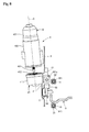
FIG. 8 is a vertical sectional view taken along the line VIII-VIII inFIG. 4 . - One embodiment of the present invention will be described with respect to the drawings. In the following description, the left in
FIG. 1 and the bottom inFIG. 2 are deemed as the front of a vehicle, and the right inFIG. 1 and the top inFIG. 2 are deemed as the back of the vehicle. - In
FIG. 1 , a sliding door (hereinafter called "door") in the vehicle is supported by anupper guide rail 1, acenter guide rail 2 and alower guide rail 3 fixed to the side of a vehicle body B and can slide longitudinally of the vehicle by electric force of a door-opening drive unit 4 (later described) mounted to the side of the vehicle body B from a fully-closed position where an entrance at the side of the vehicle body B closes to a fully-open position where the door moves backward along the side of the vehicle body B or thecenter guide rail 2 while the door slightly moves outward from the side of the vehicle body and vice versa. The top of thecenter guide rail 2 is covered with a finisher B2 fixed to the vehicle body B. - In
FIG. 2 , in a panel P that forms the side of the vehicle body B, there is formed a rectangular opening P1 through which a driven portion 41 (later described) of the door-opening drive unit 4 can be introduced from the outside to the inside of the panel P. The opening P1 is formed in such size that the drivenportion 41 of the door-openingdrive unit 4 can be introduced from the outside to the inside. - In this embodiment, in order to keep the opening P1 to a minimum, as mentioned later, the driven
portion 41 of the door-opening drive unit 4 can be attached from the outside of the vehicle, and a drive portion 42 (later described) of the door-openingdrive unit 4 can be attached from the inside of the vehicle. - In
FIG. 8 , thecenter guide rail 2 has a vertical cross-section like a channel and is fixed along a longitudinal direction of the vehicle. - In
FIGS. 2 to 7 , below the front of thecenter guide rail 2 curved toward the interior of the vehicle, a frontreversible pulley 5 as a reversible closing member on which a closing cable 10 (later described) comprising a Bowden cable is wound is rotatably mounted via avertical shaft 6, and on the upper surface of the rear of thecenter guide rail 2 extending backward straight, a reversiblerear pulley 7 as a reversible opening member on which an opening cable 11 (later described) comprising a Bowden cable is wound is rotatably mounted via avertical shaft 8. On lower part of the curved part of thecenter guide rail 2, a lowerarcuate guide member 22 for guiding theclosing cable 10 longitudinally in sliding contact therewith is fixed, and on the upper part, an upperarcuate guide member 23 for guiding theopening cable 11 longitudinally in sliding contact therewith is fixed. - The door D is connected to moving members (not shown) which move along the
upper guide rail 1 andlower guide rail 3 longitudinally and to a movingmember 9 which moves along thecenter guide rail 2 longitudinally and is supported on the vehicle body B to open and close longitudinally. - In
FIG. 8 , in the movingmember 9, aroller 93 is rotatably mounted around a vertical shaft, and aroller 94 is rotatably mounted around a horizontal shaft. Therollers center guide rail 2. So the movingmember 9 can move along thecenter guide rail 2 between a fully-open position 9A at the front end of thecenter guide rail 2 and a fully-closed position at the rear end as shown by two-dotted lines inFIG. 6 . - At the lower part of the moving
member 9, there is provided a tubularclosing coupling portion 91 coupled to the rear end of theclosing cable 10 which is wound on the frontreversible pulley 5 and extends backward. At the upper part of the movingmember 9, there is provided a tubularopening coupling portion 92 connected to the front end of theopening cable 11 which is wound around the rearreversible pulley 7 and extends forward. Theclosing coupling portion 91 and openingcoupling portion 92 are spaced from each other perpendicular to a moving direction of the movingmember 9. - The
closing coupling portion 91 andopening coupling portion 92 havetensioners 911 and 921 (FIG. 8 ) respectively, each comprising a coil spring which applies tension to theclosing cable 10 and openingcable 11 and takes up the slack of thecables - In
FIGS. 3 to 8 , the dooropening drive unit 4 comprises the drivenportion 41 mounted to the panel P and thedrive portion 42 coupled to the drivenportion 41. - The driven
portion 41 comprises an approximatelycylindrical casing 411 fixed to the panel P with abracket 21, and arotary drum 412 which is rotatably mounted via a vertical shaft in thecasing 411. In this embodiment, thecasing 411 is fixed to thebracket 21 with twobolts 14, and thebracket 21 is fixed to the panel P with twobolts 15. However, the present invention is not limited to this embodiment, and thecasing 411 may directly be fixed to the panel P without thebracket 21. - The
casing 411 comprises a tubular body located in the panel P through the opening P1 of the panel P by fixing thecasing 411 from the outside of the panel P with thebracket 21; an arm-like closing-cable outlet 411 a for reeling off theclosing cable 10 out of the panel P from therotary drum 412; and an opening-cable outlet 411b for reeling off theopening cable 11 out of the panel P. - The
rotary drum 412 is rotatably housed in the body of thecasing 411 and disposed within the panel P. On the outer circumferential surface of therotary drum 412, theclosing cable 10 for transmitting power of themotor 421 of thedrive portion 41 as door-closing force to the movingmember 9 and theopening cable 11 for transmitting it as door-opening force are wound and reeled off. - Between the front end of the closing-
cable outlet 411 a and the lower surface of the front end of thecenter guide rail 2 close to the frontreversible pulley 5, there is provided a flexible closingouter tube 12 through which theclosing cable 10 runs. Between the rear end of the opening-cable outlet 411b and the upper surface of the rear end of thecenter guide rail 2 close to the rear reversible pulley, there is provided a flexibleouter tube 13 through which theopening cable 11 runs. - The
closing cable 10 which is reeled out of therotary drum 412 runs through the closing-cable outlet 411a and the closingouter tube 12 and goes out of theouter tube 12 at the front end. Theclosing cable 10 is wound on the frontreversible pulley 5, extended backward and connected to theclosing coupling portion 91 of the movingmember 9 to move longitudinally along the lower surface of thecenter guide rail 2. Theopening cable 11 reeled out from therotary drum 412 runs through theopening cable outlet 411 b and the openingouter tube 13, and goes out of theouter tube 13 at the rear end. Theopening cable 11 is wound around the rearreversible pulley 7, extended forward and coupled to theopening coupling portion 92 to move longitudinally along the upper surface of thecenter guide rail 2. - The
rotary drum 412 is rotatably mounted in thecasing 411 via a rotary shaft (not shown) in which an axis O slightly tilts forward. (rightward inFIG. 5 ). Hence, inFIGS. 4 and5 , the closing-cable outlet 411a slightly tilts forward and downward longitudinally, and the opening-cable outlet 411b tilts backward and upward longitudinally. The closingcable 10 which is led from the front end of the closing-cable outlet 411 a can be wound on the frontreversible pulley 5 below the closingcable outlet 411 a while the closingouter tube 12 is less bent. InFIG. 8 , the axis O tilts toward the interior of the vehicle. (leftward inFIG. 8 ) Thus, while it keeps the drivenportion 41 and driveportion 42 from projecting toward the interior of the vehicle, a gap between the panel P and driveportion 42 is kept enough thereby improving connectability of thedrive portion 42. - The
drive portion 42 comprises amotor 421 which has a rotary shaft on the axis O; an approximately cylindricalvertical casing 422 coupled to the lower end of themotor 421; a reduction gear (not shown) such as a planetary gear rotatably mounted around a shaft in parallel with the axis in thecasing 422 to slow down themotor 421; and anoutput shaft 423 which projects downward to feed reduced-speed rotation of the reduction gear. Theoutput shaft 422 is inserted into and connected to therotary drum 412 from above, and the lower part of thecasing 422 is connected to the upper part of thecasing 411, so that thedrive portion 42 is connected to the drivenportion 41. Thedrive portion 42 is connected to the drivenportion 41 after the drivenportion 41 is mounted to the panel P, as described later. - Then, motion of this embodiment will be described. The moving
member 9 is positioned at a fully-closedposition 9B when the door D is in a fully-closed position, and is positioned at a fully-open position 9A when the door D is in a fully-open position. - When the door D is in the fully-closed position, a predetermined switch is operated to open the door D, and the
motor 421 is normally rotated. The normal rotation is transmitted as rotation in an opening direction to therotary drum 412 via the reduction gear of thedrive portion 42 and theoutput shaft 423. - When the
rotary drum 412 rotates in an opening direction, the openingcable 11 is wound on therotary drum 412, and theclosing cable 10 is reeled out. The movingmember 9 moves backward from the front end of the guide rail to the fully-closedposition 9A. Thus, the door D is moved from the fully-closed position to the fully-open position and stops at the fully-open position. - When the door D is in the fully-open position, the switch is operated to close the door, the
motor 421 rotates back, and therotary drum 412 rotates in a closing direction opposite the opening direction, so that the openingcable 11 is reeled out and theclosing cable 10 is wound up. The movingmember 9 moves forward from the rear end of thecenter guide rail 2 to the fully-closed position. Thus, the door D moves from the fully-open position to the fully-closed position and stops. - When the door is in the fully-closed position or when the center guide rail is exposed, the closing
cable 10 which moves along the lower surface of thecenter guide rail 2 is wound on therotary drum 412 and around the frontreversible pulley 5 under thecenter guide rail 2 connected to the movingmember 9. Hence, the closingcable 10 is not exposed. The closingcable 10 does not come into passenger's view, thereby improving appearance and preventing dust from sticking to theclosing cable 10. Meanwhile, the openingcable 11 is reeled off therotary drum 412 and exposed on the upper surface of thecenter guide rail 2, but is covered with the finisher B2. So the openingcable 11 does not come into passenger's view. Even when thecenter guide rail 2 is exposed, the closingcable 10 and openingcable 11 do not appear, thereby improving appearance. - In
FIGS. 2 and7 , before the step for fixing the panel P to thecenter guide rail 2 while thedrive portion 42 is separated from the drivenportion 41, the closingcable 10 and openingcable 11 which come from the closing-cable outlet 411a and opening-cable outlet 411b of the drivenportion 41 respectively are wound on the frontreversible pulley 5 and rearreversible pulley 7 and coupled to theclosing coupling portion 91 andopening coupling portion 92 of the movingmember 3 to constitute a rail module comprising thecenter guide rail 2, closingcable 10, openingcable 11 and drivenportion 41. - The driven
portion 41 of the rail module is inserted into the opening P1 from the outside of the panel P, and thebracket 21 formerly fixed to thecasing 411 of the drivenportion 41 is fixed to the panel P with thebolt 15. Then, thecenter guide rail 2 is fixed to the panel P with a plurality of bolts. All elements except thedrive portion 42 are connected to the vehicle body B. - Then, the
drive portion 42 is connected from the interior of the vehicle to the drivenportion 41 introduced into the opening P1 of the panel P from the exterior to the interior of the vehicle. Theoutput shaft 423 of thedrive portion 42 is connected to rotate together with therotary drum 412 enabling rotation of themotor 421 to be transmitted to each of thecables - In the embodiment of a vehicle door opening device according to the present invention, the driven
portion 41 is divided from thedrive portion 42 in the door-openingdrive unit 4, and the opening P1 through which the drivenportion 41 is introduced into the panel P from the outside to the inside of the vehicle is formed. Each of thecables portion 41 is coupled to each of thecoupling portions 91. 92 of the movingmember 9 movably connected to thecenter guide rail 2 to constitute a rail module. The drivenportion 41 of the rail module is connected from the outside of the vehicle to the panel P with thecenter guide rail 2, and then thedrive portion 42 is connected to the drivenportion 41 from the inside of the vehicle thereby reducing assembling time of each part to the vehicle body B on the vehicle assembling line. - The opening P1 of the panel P may be size enough so that the only driven
portion 41 can be introduced through the opening P1 without themotor 421 in the door-openingdrive unit 4. So adverse effect to rigidity of the panel P can be kept at minimum. - Due to the rail module comprising the
center guide rail 2, closingcable 10, openingcable 11 and drivenportion 41, thecables member 9 more efficiently before thecenter guide rail 2 is fixed to the panel P, thereby keeping down damage to thecables 10. 11 at the minimum during assembling to the vehicle body B. - The
coupling portions member 9 coupled to thecables member 9 or not across the movingmember 9 from each other. Compared with the structure in which the coupling portion is across the other coupling portion in the prior art, the present invention can reduce the size along the moving direction of the movingmember 9 and increases stroke of the movingmember 9 and opening/closing stroke of the door D. - Furthermore, the rear
reversible pulley 7 is located on the upper surface of thecenter guide rail 2, and theopening coupling portion 92 is provided on the upper part of the movingmember 9. The openingcable 11 can move along the upper surface of thecenter guide rail 2. The openingcable 11 is not seen by a passenger when the door D is closing, thereby improving its appearance and preventing mischief to theopening cable 11. - The front
reversible pulley 5 and rearreversible pulley 7 are disposed at the lower side and upper side respectively, and there is no obstacle on a moving path of the movingmember 9, thereby increasing opening/closing stroke of the door D. - The foregoing relates to an embodiment of the invention. Various modifications and changes may be made as below without departing from the gist of the invention.
-
- (i) The closing
reversible member 5 and/or openingreversible member 7 do not rotate. - (ii) The closing
reversible member 5 is located on the upper surface at the front end of thecenter guide rail 2, and the openingreversible member 7 is located under the rear end of thecenter guide rail 2. The closingcoupling portion 91 is provided at the upper part of the movingmember 9, and theclosing coupling portion 91 is provided at the lower part of the movingmember 9. However, when the door is fully closed, the advantage that the openingcable 11 is not seen by the passenger is not gained.
Claims (3)
- A vehicle door opening device in which a door is supported on a vehicle body to open and close by a motor, the device comprising:a guide rail fixed to the vehicle body;a moving member supported on the guide rail to move and connected to the door;a closing reversible member disposed at one end of the guide rail,an opening reversible member disposed at the other end of the guide rail;a closing cable wound around the closing reversible member and coupled to a closing coupling portion of the moving member to transmit rotation of the motor as door-closing force to the moving member; andan opening cable wound around the opening reversible member and coupled to a opening coupling portion of the moving member to transmit rotation of the motor as door-opening force to the moving member,wherein the closing reversible member and the opening reversible member are spaced from each other in a direction perpendicular to a moving direction of the moving member,wherein the closing coupling portion and the opening coupling portion are spaced from each other in a direction perpendicular to the moving direction of the moving member.
- The vehicle door opening device of claim 1 wherein the closing reversible member is disposed under a lower surface at one end of the guide rail; the opening reversible member is disposed on an upper surface at the other end of the guide rail; the closing coupling portion is provided on a lower part of the moving member; the opening coupling portion is provided on an upper part of the moving member; the closing cable moves along a lower surface of the center guide rail; and the opening cable moves along an upper surface of the center guide rail.
- The vehicle door opening device of claim 1 or 2 wherein the closing coupling portion and the opening coupling portion have a tensioner for giving tension to the closing cable and the opening cable respectively.
Applications Claiming Priority (2)
| Application Number | Priority Date | Filing Date | Title |
|---|---|---|---|
| JP2014022085A JP5796238B2 (en) | 2014-02-07 | 2014-02-07 | Opening and closing device for vehicle door |
| PCT/JP2014/073788 WO2015118715A1 (en) | 2014-02-07 | 2014-09-09 | Device for opening and closing vehicle door |
Publications (3)
| Publication Number | Publication Date |
|---|---|
| EP2947249A1 true EP2947249A1 (en) | 2015-11-25 |
| EP2947249A4 EP2947249A4 (en) | 2016-10-12 |
| EP2947249B1 EP2947249B1 (en) | 2020-05-13 |
Family
ID=53777535
Family Applications (1)
| Application Number | Title | Priority Date | Filing Date |
|---|---|---|---|
| EP14881425.4A Active EP2947249B1 (en) | 2014-02-07 | 2014-09-09 | Device for opening and closing vehicle door |
Country Status (5)
| Country | Link |
|---|---|
| US (1) | US9932763B2 (en) |
| EP (1) | EP2947249B1 (en) |
| JP (1) | JP5796238B2 (en) |
| CN (1) | CN105229251A (en) |
| WO (1) | WO2015118715A1 (en) |
Families Citing this family (15)
| Publication number | Priority date | Publication date | Assignee | Title |
|---|---|---|---|---|
| JP6446723B2 (en) | 2014-08-06 | 2019-01-09 | 三井金属アクト株式会社 | Door opener |
| JP6446724B2 (en) | 2014-08-06 | 2019-01-09 | 三井金属アクト株式会社 | Door opener |
| JP6446722B2 (en) | 2014-08-06 | 2019-01-09 | 三井金属アクト株式会社 | Door opener |
| DE102016102878A1 (en) * | 2016-01-12 | 2017-07-13 | Kiekert Ag | Motor vehicle door lock |
| JP6670642B2 (en) * | 2016-03-10 | 2020-03-25 | 株式会社ミツバ | Opening / closing body drive |
| CN108442846A (en) * | 2017-02-16 | 2018-08-24 | 深圳市祈飞科技有限公司 | Automatic vertical hinged door |
| CN107255730B (en) * | 2017-07-14 | 2019-07-12 | 深圳市国赛生物技术有限公司 | A kind of door switching device of specific protein analyzer |
| JP6697826B2 (en) * | 2017-12-01 | 2020-05-27 | 三井金属アクト株式会社 | Vehicle door opening and closing device and mounting method thereof |
| JP6697827B2 (en) * | 2017-12-19 | 2020-05-27 | 三井金属アクト株式会社 | Vehicle door opening and closing device and mounting method thereof |
| JP2019111881A (en) * | 2017-12-21 | 2019-07-11 | 三井金属アクト株式会社 | Slide door support device |
| CN113874591B (en) * | 2019-05-28 | 2023-04-21 | 麦格纳覆盖件有限公司 | Powered sliding door pulley assembly with tensioner and blocking feature |
| CN110359806A (en) * | 2019-06-21 | 2019-10-22 | 芜湖莫森泰克汽车科技股份有限公司 | A kind of driving mechanism for realizing sliding door of automobile L-type track |
| JP7490986B2 (en) * | 2020-03-06 | 2024-05-28 | 株式会社アイシン | Vehicle opening/closing body drive device |
| JP7586390B2 (en) * | 2021-02-26 | 2024-11-19 | 三井金属アクト株式会社 | Vehicle sliding door opening and closing device |
| JP7411305B2 (en) | 2021-04-02 | 2024-01-11 | 株式会社アイシン | sliding door drive device |
Family Cites Families (12)
| Publication number | Priority date | Publication date | Assignee | Title |
|---|---|---|---|---|
| JP2969428B2 (en) | 1995-02-28 | 1999-11-02 | 株式会社大井製作所 | Opening and closing device for sliding doors for vehicles |
| JP3618535B2 (en) * | 1998-01-14 | 2005-02-09 | 株式会社成田製作所 | Door opening and closing device |
| JP4283561B2 (en) * | 2003-02-27 | 2009-06-24 | アイシン精機株式会社 | Sliding door opening and closing device |
| US7243461B2 (en) * | 2003-03-19 | 2007-07-17 | Rogers Jr Lloyd W | Hinge mechanism for a sliding door |
| CN100519244C (en) * | 2003-09-03 | 2009-07-29 | 马自达汽车株式会社 | Vehicle slide-door supporting structure |
| US7159930B2 (en) * | 2004-03-31 | 2007-01-09 | Mitsui Mining & Smelting Co., Ltd. | Power slide device for vehicle sliding door |
| JP4098273B2 (en) * | 2004-05-11 | 2008-06-11 | 本田技研工業株式会社 | Body structure of vehicle with sliding door |
| US7770961B2 (en) * | 2006-02-20 | 2010-08-10 | Magna Closures Inc. | Compact cable drive power sliding door mechanism |
| JP4447634B2 (en) * | 2007-11-08 | 2010-04-07 | 三井金属鉱業株式会社 | Automatic opening / closing device for vehicle sliding door |
| CN202073425U (en) * | 2011-04-26 | 2011-12-14 | 奇瑞汽车股份有限公司 | Driving mechanism of power-operated sliding door |
| JP5578154B2 (en) | 2011-10-25 | 2014-08-27 | アイシン精機株式会社 | Vehicle door opening and closing device |
| JP5712952B2 (en) * | 2012-03-01 | 2015-05-07 | アイシン精機株式会社 | Vehicle door opening and closing device |
-
2014
- 2014-02-07 JP JP2014022085A patent/JP5796238B2/en active Active
- 2014-09-09 CN CN201480021765.1A patent/CN105229251A/en active Pending
- 2014-09-09 EP EP14881425.4A patent/EP2947249B1/en active Active
- 2014-09-09 US US14/771,545 patent/US9932763B2/en active Active
- 2014-09-09 WO PCT/JP2014/073788 patent/WO2015118715A1/en not_active Ceased
Also Published As
| Publication number | Publication date |
|---|---|
| US20160333626A1 (en) | 2016-11-17 |
| WO2015118715A1 (en) | 2015-08-13 |
| EP2947249A4 (en) | 2016-10-12 |
| JP2015148101A (en) | 2015-08-20 |
| EP2947249B1 (en) | 2020-05-13 |
| US9932763B2 (en) | 2018-04-03 |
| JP5796238B2 (en) | 2015-10-21 |
| CN105229251A (en) | 2016-01-06 |
Similar Documents
| Publication | Publication Date | Title |
|---|---|---|
| EP2947249B1 (en) | Device for opening and closing vehicle door | |
| JP6446723B2 (en) | Door opener | |
| JP6446724B2 (en) | Door opener | |
| JP6446722B2 (en) | Door opener | |
| US9476245B2 (en) | Door cable pulley system | |
| US9151098B2 (en) | Vehicle door opening/closing device | |
| US8464469B2 (en) | Belt driven power sliding door with belt tensioner | |
| KR930001632B1 (en) | Flush window regulator | |
| US7328934B2 (en) | Sliding door opening and closing device | |
| US20060042168A1 (en) | Vehicle door opening and closing device | |
| US20150300072A1 (en) | Automatic opening and closing apparatus for vehicle | |
| JP2007113205A (en) | Wire winding device | |
| US20230113049A1 (en) | Opening/closing device for vehicle sliding-window panel | |
| JP5796239B2 (en) | Opening and closing device for vehicle door | |
| JP5363163B2 (en) | Power slide device | |
| JP6331018B2 (en) | Door opener | |
| JP6427822B2 (en) | Door opener | |
| JP6427821B2 (en) | Door opener | |
| CN218759439U (en) | Drive device for sliding door | |
| KR101581035B1 (en) | Sliding door assembly for car | |
| JP5147005B2 (en) | Automatic door | |
| JP2022130801A (en) | Vehicle slide door opening/closing device |
Legal Events
| Date | Code | Title | Description |
|---|---|---|---|
| PUAI | Public reference made under article 153(3) epc to a published international application that has entered the european phase |
Free format text: ORIGINAL CODE: 0009012 |
|
| 17P | Request for examination filed |
Effective date: 20150817 |
|
| AK | Designated contracting states |
Kind code of ref document: A1 Designated state(s): AL AT BE BG CH CY CZ DE DK EE ES FI FR GB GR HR HU IE IS IT LI LT LU LV MC MK MT NL NO PL PT RO RS SE SI SK SM TR |
|
| AX | Request for extension of the european patent |
Extension state: BA ME |
|
| A4 | Supplementary search report drawn up and despatched |
Effective date: 20160909 |
|
| RIC1 | Information provided on ipc code assigned before grant |
Ipc: E05F 11/54 20060101AFI20160905BHEP Ipc: B60J 5/06 20060101ALI20160905BHEP Ipc: E05F 15/646 20150101ALI20160905BHEP Ipc: B60J 5/04 20060101ALI20160905BHEP |
|
| DAX | Request for extension of the european patent (deleted) | ||
| STAA | Information on the status of an ep patent application or granted ep patent |
Free format text: STATUS: EXAMINATION IS IN PROGRESS |
|
| 17Q | First examination report despatched |
Effective date: 20180126 |
|
| GRAP | Despatch of communication of intention to grant a patent |
Free format text: ORIGINAL CODE: EPIDOSNIGR1 |
|
| STAA | Information on the status of an ep patent application or granted ep patent |
Free format text: STATUS: GRANT OF PATENT IS INTENDED |
|
| INTG | Intention to grant announced |
Effective date: 20190913 |
|
| GRAJ | Information related to disapproval of communication of intention to grant by the applicant or resumption of examination proceedings by the epo deleted |
Free format text: ORIGINAL CODE: EPIDOSDIGR1 |
|
| INTG | Intention to grant announced |
Effective date: 20190919 |
|
| GRAP | Despatch of communication of intention to grant a patent |
Free format text: ORIGINAL CODE: EPIDOSNIGR1 |
|
| GRAJ | Information related to disapproval of communication of intention to grant by the applicant or resumption of examination proceedings by the epo deleted |
Free format text: ORIGINAL CODE: EPIDOSDIGR1 |
|
| GRAJ | Information related to disapproval of communication of intention to grant by the applicant or resumption of examination proceedings by the epo deleted |
Free format text: ORIGINAL CODE: EPIDOSDIGR1 |
|
| GRAP | Despatch of communication of intention to grant a patent |
Free format text: ORIGINAL CODE: EPIDOSNIGR1 |
|
| STAA | Information on the status of an ep patent application or granted ep patent |
Free format text: STATUS: EXAMINATION IS IN PROGRESS |
|
| INTG | Intention to grant announced |
Effective date: 20191018 |
|
| INTG | Intention to grant announced |
Effective date: 20191108 |
|
| INTC | Intention to grant announced (deleted) | ||
| GRAP | Despatch of communication of intention to grant a patent |
Free format text: ORIGINAL CODE: EPIDOSNIGR1 |
|
| STAA | Information on the status of an ep patent application or granted ep patent |
Free format text: STATUS: GRANT OF PATENT IS INTENDED |
|
| INTG | Intention to grant announced |
Effective date: 20200205 |
|
| GRAS | Grant fee paid |
Free format text: ORIGINAL CODE: EPIDOSNIGR3 |
|
| GRAA | (expected) grant |
Free format text: ORIGINAL CODE: 0009210 |
|
| STAA | Information on the status of an ep patent application or granted ep patent |
Free format text: STATUS: THE PATENT HAS BEEN GRANTED |
|
| AK | Designated contracting states |
Kind code of ref document: B1 Designated state(s): AL AT BE BG CH CY CZ DE DK EE ES FI FR GB GR HR HU IE IS IT LI LT LU LV MC MK MT NL NO PL PT RO RS SE SI SK SM TR |
|
| REG | Reference to a national code |
Ref country code: GB Ref legal event code: FG4D |
|
| REG | Reference to a national code |
Ref country code: CH Ref legal event code: EP |
|
| REG | Reference to a national code |
Ref country code: DE Ref legal event code: R096 Ref document number: 602014065554 Country of ref document: DE |
|
| REG | Reference to a national code |
Ref country code: AT Ref legal event code: REF Ref document number: 1270496 Country of ref document: AT Kind code of ref document: T Effective date: 20200615 |
|
| REG | Reference to a national code |
Ref country code: LT Ref legal event code: MG4D |
|
| REG | Reference to a national code |
Ref country code: NL Ref legal event code: MP Effective date: 20200513 |
|
| PG25 | Lapsed in a contracting state [announced via postgrant information from national office to epo] |
Ref country code: PT Free format text: LAPSE BECAUSE OF FAILURE TO SUBMIT A TRANSLATION OF THE DESCRIPTION OR TO PAY THE FEE WITHIN THE PRESCRIBED TIME-LIMIT Effective date: 20200914 Ref country code: IS Free format text: LAPSE BECAUSE OF FAILURE TO SUBMIT A TRANSLATION OF THE DESCRIPTION OR TO PAY THE FEE WITHIN THE PRESCRIBED TIME-LIMIT Effective date: 20200913 Ref country code: FI Free format text: LAPSE BECAUSE OF FAILURE TO SUBMIT A TRANSLATION OF THE DESCRIPTION OR TO PAY THE FEE WITHIN THE PRESCRIBED TIME-LIMIT Effective date: 20200513 Ref country code: LT Free format text: LAPSE BECAUSE OF FAILURE TO SUBMIT A TRANSLATION OF THE DESCRIPTION OR TO PAY THE FEE WITHIN THE PRESCRIBED TIME-LIMIT Effective date: 20200513 Ref country code: SE Free format text: LAPSE BECAUSE OF FAILURE TO SUBMIT A TRANSLATION OF THE DESCRIPTION OR TO PAY THE FEE WITHIN THE PRESCRIBED TIME-LIMIT Effective date: 20200513 Ref country code: GR Free format text: LAPSE BECAUSE OF FAILURE TO SUBMIT A TRANSLATION OF THE DESCRIPTION OR TO PAY THE FEE WITHIN THE PRESCRIBED TIME-LIMIT Effective date: 20200814 Ref country code: NO Free format text: LAPSE BECAUSE OF FAILURE TO SUBMIT A TRANSLATION OF THE DESCRIPTION OR TO PAY THE FEE WITHIN THE PRESCRIBED TIME-LIMIT Effective date: 20200813 |
|
| PG25 | Lapsed in a contracting state [announced via postgrant information from national office to epo] |
Ref country code: BG Free format text: LAPSE BECAUSE OF FAILURE TO SUBMIT A TRANSLATION OF THE DESCRIPTION OR TO PAY THE FEE WITHIN THE PRESCRIBED TIME-LIMIT Effective date: 20200813 Ref country code: RS Free format text: LAPSE BECAUSE OF FAILURE TO SUBMIT A TRANSLATION OF THE DESCRIPTION OR TO PAY THE FEE WITHIN THE PRESCRIBED TIME-LIMIT Effective date: 20200513 Ref country code: LV Free format text: LAPSE BECAUSE OF FAILURE TO SUBMIT A TRANSLATION OF THE DESCRIPTION OR TO PAY THE FEE WITHIN THE PRESCRIBED TIME-LIMIT Effective date: 20200513 Ref country code: HR Free format text: LAPSE BECAUSE OF FAILURE TO SUBMIT A TRANSLATION OF THE DESCRIPTION OR TO PAY THE FEE WITHIN THE PRESCRIBED TIME-LIMIT Effective date: 20200513 |
|
| REG | Reference to a national code |
Ref country code: AT Ref legal event code: MK05 Ref document number: 1270496 Country of ref document: AT Kind code of ref document: T Effective date: 20200513 |
|
| PG25 | Lapsed in a contracting state [announced via postgrant information from national office to epo] |
Ref country code: AL Free format text: LAPSE BECAUSE OF FAILURE TO SUBMIT A TRANSLATION OF THE DESCRIPTION OR TO PAY THE FEE WITHIN THE PRESCRIBED TIME-LIMIT Effective date: 20200513 Ref country code: NL Free format text: LAPSE BECAUSE OF FAILURE TO SUBMIT A TRANSLATION OF THE DESCRIPTION OR TO PAY THE FEE WITHIN THE PRESCRIBED TIME-LIMIT Effective date: 20200513 |
|
| PG25 | Lapsed in a contracting state [announced via postgrant information from national office to epo] |
Ref country code: DK Free format text: LAPSE BECAUSE OF FAILURE TO SUBMIT A TRANSLATION OF THE DESCRIPTION OR TO PAY THE FEE WITHIN THE PRESCRIBED TIME-LIMIT Effective date: 20200513 Ref country code: ES Free format text: LAPSE BECAUSE OF FAILURE TO SUBMIT A TRANSLATION OF THE DESCRIPTION OR TO PAY THE FEE WITHIN THE PRESCRIBED TIME-LIMIT Effective date: 20200513 Ref country code: EE Free format text: LAPSE BECAUSE OF FAILURE TO SUBMIT A TRANSLATION OF THE DESCRIPTION OR TO PAY THE FEE WITHIN THE PRESCRIBED TIME-LIMIT Effective date: 20200513 Ref country code: SM Free format text: LAPSE BECAUSE OF FAILURE TO SUBMIT A TRANSLATION OF THE DESCRIPTION OR TO PAY THE FEE WITHIN THE PRESCRIBED TIME-LIMIT Effective date: 20200513 Ref country code: AT Free format text: LAPSE BECAUSE OF FAILURE TO SUBMIT A TRANSLATION OF THE DESCRIPTION OR TO PAY THE FEE WITHIN THE PRESCRIBED TIME-LIMIT Effective date: 20200513 Ref country code: CZ Free format text: LAPSE BECAUSE OF FAILURE TO SUBMIT A TRANSLATION OF THE DESCRIPTION OR TO PAY THE FEE WITHIN THE PRESCRIBED TIME-LIMIT Effective date: 20200513 Ref country code: IT Free format text: LAPSE BECAUSE OF FAILURE TO SUBMIT A TRANSLATION OF THE DESCRIPTION OR TO PAY THE FEE WITHIN THE PRESCRIBED TIME-LIMIT Effective date: 20200513 Ref country code: RO Free format text: LAPSE BECAUSE OF FAILURE TO SUBMIT A TRANSLATION OF THE DESCRIPTION OR TO PAY THE FEE WITHIN THE PRESCRIBED TIME-LIMIT Effective date: 20200513 |
|
| REG | Reference to a national code |
Ref country code: DE Ref legal event code: R097 Ref document number: 602014065554 Country of ref document: DE |
|
| PG25 | Lapsed in a contracting state [announced via postgrant information from national office to epo] |
Ref country code: PL Free format text: LAPSE BECAUSE OF FAILURE TO SUBMIT A TRANSLATION OF THE DESCRIPTION OR TO PAY THE FEE WITHIN THE PRESCRIBED TIME-LIMIT Effective date: 20200513 Ref country code: SK Free format text: LAPSE BECAUSE OF FAILURE TO SUBMIT A TRANSLATION OF THE DESCRIPTION OR TO PAY THE FEE WITHIN THE PRESCRIBED TIME-LIMIT Effective date: 20200513 |
|
| PLBE | No opposition filed within time limit |
Free format text: ORIGINAL CODE: 0009261 |
|
| STAA | Information on the status of an ep patent application or granted ep patent |
Free format text: STATUS: NO OPPOSITION FILED WITHIN TIME LIMIT |
|
| 26N | No opposition filed |
Effective date: 20210216 |
|
| PG25 | Lapsed in a contracting state [announced via postgrant information from national office to epo] |
Ref country code: MC Free format text: LAPSE BECAUSE OF FAILURE TO SUBMIT A TRANSLATION OF THE DESCRIPTION OR TO PAY THE FEE WITHIN THE PRESCRIBED TIME-LIMIT Effective date: 20200513 |
|
| REG | Reference to a national code |
Ref country code: CH Ref legal event code: PL |
|
| GBPC | Gb: european patent ceased through non-payment of renewal fee |
Effective date: 20200909 |
|
| PG25 | Lapsed in a contracting state [announced via postgrant information from national office to epo] |
Ref country code: SI Free format text: LAPSE BECAUSE OF FAILURE TO SUBMIT A TRANSLATION OF THE DESCRIPTION OR TO PAY THE FEE WITHIN THE PRESCRIBED TIME-LIMIT Effective date: 20200513 |
|
| REG | Reference to a national code |
Ref country code: BE Ref legal event code: MM Effective date: 20200930 |
|
| PG25 | Lapsed in a contracting state [announced via postgrant information from national office to epo] |
Ref country code: LU Free format text: LAPSE BECAUSE OF NON-PAYMENT OF DUE FEES Effective date: 20200909 |
|
| PG25 | Lapsed in a contracting state [announced via postgrant information from national office to epo] |
Ref country code: FR Free format text: LAPSE BECAUSE OF NON-PAYMENT OF DUE FEES Effective date: 20200930 |
|
| PG25 | Lapsed in a contracting state [announced via postgrant information from national office to epo] |
Ref country code: IE Free format text: LAPSE BECAUSE OF NON-PAYMENT OF DUE FEES Effective date: 20200909 Ref country code: LI Free format text: LAPSE BECAUSE OF NON-PAYMENT OF DUE FEES Effective date: 20200930 Ref country code: GB Free format text: LAPSE BECAUSE OF NON-PAYMENT OF DUE FEES Effective date: 20200909 Ref country code: CH Free format text: LAPSE BECAUSE OF NON-PAYMENT OF DUE FEES Effective date: 20200930 Ref country code: BE Free format text: LAPSE BECAUSE OF NON-PAYMENT OF DUE FEES Effective date: 20200930 |
|
| PG25 | Lapsed in a contracting state [announced via postgrant information from national office to epo] |
Ref country code: TR Free format text: LAPSE BECAUSE OF FAILURE TO SUBMIT A TRANSLATION OF THE DESCRIPTION OR TO PAY THE FEE WITHIN THE PRESCRIBED TIME-LIMIT Effective date: 20200513 Ref country code: MT Free format text: LAPSE BECAUSE OF FAILURE TO SUBMIT A TRANSLATION OF THE DESCRIPTION OR TO PAY THE FEE WITHIN THE PRESCRIBED TIME-LIMIT Effective date: 20200513 Ref country code: CY Free format text: LAPSE BECAUSE OF FAILURE TO SUBMIT A TRANSLATION OF THE DESCRIPTION OR TO PAY THE FEE WITHIN THE PRESCRIBED TIME-LIMIT Effective date: 20200513 |
|
| PG25 | Lapsed in a contracting state [announced via postgrant information from national office to epo] |
Ref country code: MK Free format text: LAPSE BECAUSE OF FAILURE TO SUBMIT A TRANSLATION OF THE DESCRIPTION OR TO PAY THE FEE WITHIN THE PRESCRIBED TIME-LIMIT Effective date: 20200513 |
|
| PGFP | Annual fee paid to national office [announced via postgrant information from national office to epo] |
Ref country code: DE Payment date: 20240730 Year of fee payment: 11 |