EP2947246A1 - Snap hinge with damped closing - Google Patents
Snap hinge with damped closing Download PDFInfo
- Publication number
- EP2947246A1 EP2947246A1 EP15168266.3A EP15168266A EP2947246A1 EP 2947246 A1 EP2947246 A1 EP 2947246A1 EP 15168266 A EP15168266 A EP 15168266A EP 2947246 A1 EP2947246 A1 EP 2947246A1
- Authority
- EP
- European Patent Office
- Prior art keywords
- lever
- hinge
- articulated
- coupling plate
- plate
- Prior art date
- Legal status (The legal status is an assumption and is not a legal conclusion. Google has not performed a legal analysis and makes no representation as to the accuracy of the status listed.)
- Granted
Links
Images


Classifications
-
- E—FIXED CONSTRUCTIONS
- E05—LOCKS; KEYS; WINDOW OR DOOR FITTINGS; SAFES
- E05D—HINGES OR SUSPENSION DEVICES FOR DOORS, WINDOWS OR WINGS
- E05D3/00—Hinges with pins
- E05D3/06—Hinges with pins with two or more pins
- E05D3/16—Hinges with pins with two or more pins with seven parallel pins and four arms
-
- E—FIXED CONSTRUCTIONS
- E05—LOCKS; KEYS; WINDOW OR DOOR FITTINGS; SAFES
- E05D—HINGES OR SUSPENSION DEVICES FOR DOORS, WINDOWS OR WINGS
- E05D11/00—Additional features or accessories of hinges
- E05D11/10—Devices for preventing movement between relatively-movable hinge parts
- E05D11/1028—Devices for preventing movement between relatively-movable hinge parts for maintaining the hinge in two or more positions, e.g. intermediate or fully open
- E05D11/105—Devices for preventing movement between relatively-movable hinge parts for maintaining the hinge in two or more positions, e.g. intermediate or fully open the maintaining means acting perpendicularly to the pivot axis
-
- E—FIXED CONSTRUCTIONS
- E05—LOCKS; KEYS; WINDOW OR DOOR FITTINGS; SAFES
- E05F—DEVICES FOR MOVING WINGS INTO OPEN OR CLOSED POSITION; CHECKS FOR WINGS; WING FITTINGS NOT OTHERWISE PROVIDED FOR, CONCERNED WITH THE FUNCTIONING OF THE WING
- E05F3/00—Closers or openers with braking devices, e.g. checks; Construction of pneumatic or liquid braking devices
- E05F3/20—Closers or openers with braking devices, e.g. checks; Construction of pneumatic or liquid braking devices in hinges
-
- E—FIXED CONSTRUCTIONS
- E05—LOCKS; KEYS; WINDOW OR DOOR FITTINGS; SAFES
- E05F—DEVICES FOR MOVING WINGS INTO OPEN OR CLOSED POSITION; CHECKS FOR WINGS; WING FITTINGS NOT OTHERWISE PROVIDED FOR, CONCERNED WITH THE FUNCTIONING OF THE WING
- E05F5/00—Braking devices, e.g. checks; Stops; Buffers
- E05F5/06—Buffers or stops limiting opening of swinging wings, e.g. floor or wall stops
- E05F5/10—Buffers or stops limiting opening of swinging wings, e.g. floor or wall stops with piston brakes
-
- E—FIXED CONSTRUCTIONS
- E05—LOCKS; KEYS; WINDOW OR DOOR FITTINGS; SAFES
- E05D—HINGES OR SUSPENSION DEVICES FOR DOORS, WINDOWS OR WINGS
- E05D3/00—Hinges with pins
- E05D3/06—Hinges with pins with two or more pins
- E05D3/16—Hinges with pins with two or more pins with seven parallel pins and four arms
- E05D2003/163—Horizontal pivot-axis
-
- E—FIXED CONSTRUCTIONS
- E05—LOCKS; KEYS; WINDOW OR DOOR FITTINGS; SAFES
- E05Y—INDEXING SCHEME RELATING TO HINGES OR OTHER SUSPENSION DEVICES FOR DOORS, WINDOWS OR WINGS AND DEVICES FOR MOVING WINGS INTO OPEN OR CLOSED POSITION, CHECKS FOR WINGS AND WING FITTINGS NOT OTHERWISE PROVIDED FOR, CONCERNED WITH THE FUNCTIONING OF THE WING
- E05Y2900/00—Application of doors, windows, wings or fittings thereof
- E05Y2900/20—Application of doors, windows, wings or fittings thereof for furnitures, e.g. cabinets
Definitions
- the present invention relates to a snap hinge with damped closing.
- hinges which are interposed between a movable leaf and a structural frame that defines a compartment that is closed by said leaf, so as to allow the relative rotation of the leaf with respect to the frame between a closed configuration and an open configuration.
- hinges are constituted substantially by two articulated quadrilaterals, having two levers in common, and are preferably provided with elastic means for maintaining the closed configuration, so as to avoid the accidental opening of the leaf.
- damping elements are particularly useful in applications in which the leaf has a substantially vertical arrangement and is hinged in an upward region about a substantially horizontal axis, in order to prevent the leaf from slamming against the structure under the action of its own weight.
- a version of snap hinge in which the damping element is interposed between the plate for fixing the hinge to the leaf, which acts as a frame for the adjacent articulated quadrilateral, and an arm of said quadrilateral.
- This configuration in view of the bulk of the damping element in the closed configuration, prevents the leaf from performing a rotation of more than 90° between the open and closed configurations.
- solutions that, without modifying the shape of the structural elements, allow an arrangement that is inclined at an angle of less than 90° of the leaf in the closed configuration with respect to the horizontal upper frame, so as to increase the useful space available to passengers, are interesting.
- damping element can be arranged also between the plate for coupling to the fixed structure and the articulated quadrilateral that is adjacent thereto, by interposition of additional elements for the pivoting of said element.
- the aim of the present invention is to eliminate the drawbacks cited above of the known solutions, by devising a snap hinge with damped closing that allows to increase the movement angle of the leaf between the open and closed configurations and therefore the flexibility of application of said hinge, without increasing the complexity of its structure.
- Another object of the present invention is to be economically convenient and competitive, and to be highly reliable and durable in operation.
- a further object of the present invention is to provide a structure that is simple, relatively easy to provide in practice, safe in use, effective in operation and relatively low in cost.
- the present snap hinge with damped closing comprising a first articulated quadrilateral that comprises a coupling plate that can be associated with a fixed element, a first lever and a third lever, which are articulated to said coupling plate, and a second lever, which is interposed between the preceding levers and is articulated thereto, and a second articulated quadrilateral that comprises a fixing plate that can be associated with a movable element with which are associated and articulated respective ends of said second lever and of a fourth lever, the opposite end of which is associated and articulated with said first lever, the hinge being adapted to assume alternately an open configuration and a closed configuration, in which said plates have various main arrangements with respect to each other, rotating about a substantially horizontal rotation axis, characterized in that it comprises at least one damping element that acts during closing and is interposed directly between said coupling plate and said second lever, the damping element having mutually opposite ends thereof articulated about respective fixed pivots associated with the fixing plate and with the second lever.
- a snap hinge with damped closing has been designated generally by the reference numeral 1.
- the hinge 1 comprises a first articulated quadrilateral 2, constituted by a plate 3 for coupling to a fixed element 101, by a first lever 4 and by a third lever 5 having respective first ends associated with the coupling plate 3 by means of respective pivoting pivots 6 and 7 and by a second lever 8 that is interposed between the previous ones and is articulated thereto about respective pivoting pivots 9 and 10.
- the coupling plate 3 has a pair of first side walls 27 for supporting the pivots 6 and 7, only one of which is shown in the figures and which protrude from the main plane of arrangement of said plate on the side that lies opposite the one intended to adhere to the fixed element 101.
- the hinge 1 comprises, moreover, a second articulated quadrilateral 11 having two levers in common with the first articulated quadrilateral 2.
- the second articulated quadrilateral 11 is composed of a plate 12 for fixing to a movable element 102, by the second lever 8, which has an end pivoted to said plate about a respective pivot 13, by a fourth lever 14, the opposite ends of which are pivoted to the fixing plate 12 and to the first lever 4 about respective pivots 15 and 16, and by said first lever.
- the fixing plate 12 is provided with a pair of second side walls 28 for supporting the pivots 13 and 15, only one of which is shown in the figures and which protrude from the main plane of arrangement of said plate on the side that lies opposite the one intended to adhere to the movable element 102.
- the hinge 1 is intended to be interposed between a fixed element 101, such as a wall of a frame wall of a furniture element that defines a compartment, and a movable element 102, such as a leaf for closing said compartment.
- a fixed element 101 such as a wall of a frame wall of a furniture element that defines a compartment
- a movable element 102 such as a leaf for closing said compartment.
- the hinge 1 is adapted to be moved between a closed configuration and an open configuration, in which the coupling plate 3 and the fixing plate 12 have mutually different main arrangements, rotating about a substantially horizontal rotation axis.
- the hinge 1 is particularly intended to be mounted on furniture elements in which the movable element 102 hangs from the fixed element 101 arranged in an upward region and articulated thereto about a substantially horizontal axis, such as the shelves typically provided in campers, caravans and the like.
- the hinge 1 has at least one damping element 17 that acts during closing and is directly interposed between the coupling plate 3 and the second lever 8, with the corresponding ends articulated about respective pivots 18 and 19 that are fixed and associated, respectively, with the coupling plate 3 and with the second lever 8.
- the presence of the damping element 17 prevents the movable element 102 from closing violently under the action of its own weight even if it is not guided by the user.
- the damping element 17 comprises a cylindrical jacket 20 in which a stem 21 is inserted slidingly.
- the jacket 20 and the stem 21 are associated respectively with the second lever 8 and with the coupling plate 3 by way of the pivots 19 and 18.
- the damping element 17 In the open configuration of the hinge 1, the damping element 17 is in a compression position, with the stem 21 retracted inside the jacket 20, while in the closed configuration the damping element 17 is in an extension position, with the stem 21 that protrudes from the jacket 20.
- the damping element 17 comprises braking means of a known type, such as one-way valves not detailed in the drawings, for the decelerated transition from the compression position to the extension position.
- the second lever 8 comprises a tab 22 that protrudes beyond the pivot 9 for pivoting to the first lever 4, at which there is the pivot 19 for pivoting said second lever with the jacket 20.
- the coupling plate 3 is provided with a pair of wings 23, only one of which is shown in the figures, for supporting the pivot 18 for pivoting the stem 21 to said plate, so as to avoid lateral movements of the stem 21 with respect to its longitudinal extension.
- the fist lever 4 has at least one central portion 24 that is saddle-shaped so as to accommodate in the corresponding concave region the tab 22 and the damping element 17.
- the first lever 4 is constituted by two plates 25 that are contoured and arranged parallel to each other and between which a connecting bridge 26 is interposed at the central portion 24.
- the plates 25 are arranged on opposite sides of the fourth lever 14, while at the pivot 6 the plates 25 are arranged inside the first side walls 27.
- first elastic means 29 for maintaining the open configuration which are interposed between the levers of the second articulated quadrilateral 11, which support the weight of the movable element 102 in the open configuration.
- the first elastic means 29 can provide an encapsulated spring pivoted to the pivot 16 for the pivoting of the fourth and first levers, respectively, 14 and 4, and to a further pivot 30 associated with the second lever 8 between the pivots 9 and 10.
- second elastic means 32 for maintaining the open configuration which are interposed between the elements of the first articulated quadrilateral 2, which cooperate with the first elastic means 29 to support the weight of the movable element 102 in the open configuration.
- the second elastic means 32 are interposed between the coupling plate 3 and the first lever 4 and can provide an encapsulated spring that is pivoted to the coupling plate 3 and to the first lever 4 about respective pivots 33 and 34.
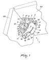
- Figures 1 to 3 show a first embodiment of the hinge according to the invention, in which the coupling plate 3 and the fixing plate 12 have their respective main arrangements that define an acute angle in the closed configuration ( Figures 1 and 2 ) and are substantially parallel in the open configuration ( Figure 3 ), the rotation angle between the open and closed configurations being greater than 90°.
- this version is intended to be applied to furniture in which the fixed element 101 has a horizontal or substantially horizontal arrangement and the movable element 102 is pivoted in an upward region about a horizontal axis.
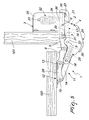
- Figures 4 to 6 show a second embodiment of the hinge according to the invention, in which the coupling plate 3 and the fixing plate 12 have the respective main arrangements that define an obtuse angle that is close to 180° in the closed configuration ( Figure 6 ) and are substantially perpendicular in open configuration ( Figures 4 and 5 ), the rotation angle between the open and closed configurations being greater than 90°.
- both the first and second elastic means are provided.
- the coupling plate 3 is composed of a substantially box-like main body 35 that defines the side walls 27 and on which the wings 23 are applied.
- the pivot 33 is associated with the main body 35 and the first lever 4 extends beyond the pivot 6 at the corresponding first end to define a protrusion 36 that is accommodated so that it can move inside the main body 35.
- this version is designed to be applied to furniture in which the fixed element 101 has a vertical or substantially vertical arrangement and the movable element 102 rotates about a horizontal axis.
- solutions according to the invention do not entail structural complications, but only the geometric modification of some components.
Abstract
Description
- The present invention relates to a snap hinge with damped closing.
- With particular reference to the field of furniture, hinges are known which are interposed between a movable leaf and a structural frame that defines a compartment that is closed by said leaf, so as to allow the relative rotation of the leaf with respect to the frame between a closed configuration and an open configuration.
- These hinges are constituted substantially by two articulated quadrilaterals, having two levers in common, and are preferably provided with elastic means for maintaining the closed configuration, so as to avoid the accidental opening of the leaf.
- However, the presence of such elastic means, which are indispensable in some applications, involves a sudden closure of the leaf, which, if not accompanied, collides violently against the supporting structure, with the further risk of crushing for the users or for any objects not stored correctly in the compartment.
- In order to obviate these drawbacks, various solutions have been developed in order to obtain a damped closure which provide for the insertion of closure damping elements that are external to the hinge or are directly embedded.
- These damping elements are particularly useful in applications in which the leaf has a substantially vertical arrangement and is hinged in an upward region about a substantially horizontal axis, in order to prevent the leaf from slamming against the structure under the action of its own weight.
- Among solutions with embedded damping elements, in particular, a version of snap hinge is known in which the damping element is interposed between the plate for fixing the hinge to the leaf, which acts as a frame for the adjacent articulated quadrilateral, and an arm of said quadrilateral.
- This configuration, in view of the bulk of the damping element in the closed configuration, prevents the leaf from performing a rotation of more than 90° between the open and closed configurations.
- In some applications, for example for shelves of caravans or vehicles in general, solutions that, without modifying the shape of the structural elements, allow an arrangement that is inclined at an angle of less than 90° of the leaf in the closed configuration with respect to the horizontal upper frame, so as to increase the useful space available to passengers, are interesting.
- As an alternative, solutions are known in which the damping element can be arranged also between the plate for coupling to the fixed structure and the articulated quadrilateral that is adjacent thereto, by interposition of additional elements for the pivoting of said element.
- These solutions, too, are not devoid of drawbacks, which include the fact that they entail the provision and assembly of additional elements, which increase the complexity of the structure of the hinge, increasing its production costs and reducing its reliability, in view of the greater likelihood of breakages or jamming.
- The aim of the present invention is to eliminate the drawbacks cited above of the known solutions, by devising a snap hinge with damped closing that allows to increase the movement angle of the leaf between the open and closed configurations and therefore the flexibility of application of said hinge, without increasing the complexity of its structure.
- Within this aim, another object of the present invention is to be economically convenient and competitive, and to be highly reliable and durable in operation.
- A further object of the present invention is to provide a structure that is simple, relatively easy to provide in practice, safe in use, effective in operation and relatively low in cost.
- This aim and these objects are all achieved by the present snap hinge with damped closing, comprising a first articulated quadrilateral that comprises a coupling plate that can be associated with a fixed element, a first lever and a third lever, which are articulated to said coupling plate, and a second lever, which is interposed between the preceding levers and is articulated thereto, and a second articulated quadrilateral that comprises a fixing plate that can be associated with a movable element with which are associated and articulated respective ends of said second lever and of a fourth lever, the opposite end of which is associated and articulated with said first lever, the hinge being adapted to assume alternately an open configuration and a closed configuration, in which said plates have various main arrangements with respect to each other, rotating about a substantially horizontal rotation axis, characterized in that it comprises at least one damping element that acts during closing and is interposed directly between said coupling plate and said second lever, the damping element having mutually opposite ends thereof articulated about respective fixed pivots associated with the fixing plate and with the second lever.
- Further characteristics and advantages of the present invention will become better apparent from the detailed description of two preferred but not exclusive embodiments of a snap hinge with damped closing, illustrated by way of non-limiting example in the accompanying drawings, wherein:
-
Figure 1 is a schematic perspective bottom view of a first embodiment of a snap hinge with damped closing, according to the invention, in the closed configuration; -
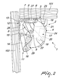
Figure 2 is a schematic side elevation view of the hinge ofFigure 1 ; -
Figure 3 is a schematic side elevation view as inFigure 2 , but in the open configuration; -
Figure 4 is a schematic perspective bottom view of a second embodiment of a snap hinge with damped closing, according to the invention, in the open configuration; -
Figure 5 is a schematic side elevation view of the hinge ofFigure 4 ; -
Figure 6 is a schematic side elevation view as inFigure 5 , but in the closed configuration. - With reference to the figures, a snap hinge with damped closing has been designated generally by the
reference numeral 1. - The
hinge 1 comprises a first articulated quadrilateral 2, constituted by aplate 3 for coupling to afixed element 101, by afirst lever 4 and by athird lever 5 having respective first ends associated with thecoupling plate 3 by means ofrespective pivoting pivots second lever 8 that is interposed between the previous ones and is articulated thereto aboutrespective pivoting pivots - The
coupling plate 3 has a pair offirst side walls 27 for supporting thepivots fixed element 101. - The
hinge 1 comprises, moreover, a second articulated quadrilateral 11 having two levers in common with the first articulated quadrilateral 2. - In particular, the second articulated quadrilateral 11 is composed of a
plate 12 for fixing to amovable element 102, by thesecond lever 8, which has an end pivoted to said plate about arespective pivot 13, by afourth lever 14, the opposite ends of which are pivoted to thefixing plate 12 and to thefirst lever 4 aboutrespective pivots - The
fixing plate 12 is provided with a pair ofsecond side walls 28 for supporting thepivots movable element 102. - In use, the
hinge 1 is intended to be interposed between afixed element 101, such as a wall of a frame wall of a furniture element that defines a compartment, and amovable element 102, such as a leaf for closing said compartment. - Therefore, the
hinge 1 is adapted to be moved between a closed configuration and an open configuration, in which thecoupling plate 3 and thefixing plate 12 have mutually different main arrangements, rotating about a substantially horizontal rotation axis. - The
hinge 1 is particularly intended to be mounted on furniture elements in which themovable element 102 hangs from thefixed element 101 arranged in an upward region and articulated thereto about a substantially horizontal axis, such as the shelves typically provided in campers, caravans and the like. - According to the invention, the
hinge 1 has at least onedamping element 17 that acts during closing and is directly interposed between thecoupling plate 3 and thesecond lever 8, with the corresponding ends articulated aboutrespective pivots coupling plate 3 and with thesecond lever 8. - In the application described above, the presence of the
damping element 17 prevents themovable element 102 from closing violently under the action of its own weight even if it is not guided by the user. - In greater detail, the
damping element 17 comprises acylindrical jacket 20 in which astem 21 is inserted slidingly. Thejacket 20 and thestem 21 are associated respectively with thesecond lever 8 and with thecoupling plate 3 by way of thepivots - In the open configuration of the
hinge 1, thedamping element 17 is in a compression position, with thestem 21 retracted inside thejacket 20, while in the closed configuration thedamping element 17 is in an extension position, with thestem 21 that protrudes from thejacket 20. Thedamping element 17 comprises braking means of a known type, such as one-way valves not detailed in the drawings, for the decelerated transition from the compression position to the extension position. - The
second lever 8 comprises atab 22 that protrudes beyond thepivot 9 for pivoting to thefirst lever 4, at which there is thepivot 19 for pivoting said second lever with thejacket 20. - Moreover, the
coupling plate 3 is provided with a pair ofwings 23, only one of which is shown in the figures, for supporting thepivot 18 for pivoting thestem 21 to said plate, so as to avoid lateral movements of thestem 21 with respect to its longitudinal extension. - Advantageously, the
fist lever 4 has at least onecentral portion 24 that is saddle-shaped so as to accommodate in the corresponding concave region thetab 22 and thedamping element 17. - More precisely, the
first lever 4 is constituted by twoplates 25 that are contoured and arranged parallel to each other and between which a connectingbridge 26 is interposed at thecentral portion 24. - At the
pivot 16 theplates 25 are arranged on opposite sides of thefourth lever 14, while at thepivot 6 theplates 25 are arranged inside thefirst side walls 27. - Moreover, there can be first
elastic means 29 for maintaining the open configuration which are interposed between the levers of the second articulated quadrilateral 11, which support the weight of themovable element 102 in the open configuration. - The first
elastic means 29 can provide an encapsulated spring pivoted to thepivot 16 for the pivoting of the fourth and first levers, respectively, 14 and 4, and to afurther pivot 30 associated with thesecond lever 8 between thepivots - There can be, furthermore, second elastic means 32 for maintaining the open configuration which are interposed between the elements of the first articulated quadrilateral 2, which cooperate with the first
elastic means 29 to support the weight of themovable element 102 in the open configuration. In particular, the secondelastic means 32 are interposed between thecoupling plate 3 and thefirst lever 4 and can provide an encapsulated spring that is pivoted to thecoupling plate 3 and to thefirst lever 4 aboutrespective pivots -
Figures 1 to 3 show a first embodiment of the hinge according to the invention, in which thecoupling plate 3 and thefixing plate 12 have their respective main arrangements that define an acute angle in the closed configuration (Figures 1 and2 ) and are substantially parallel in the open configuration (Figure 3 ), the rotation angle between the open and closed configurations being greater than 90°. - In this case only the first
elastic means 29 are provided. - Typically, this version is intended to be applied to furniture in which the
fixed element 101 has a horizontal or substantially horizontal arrangement and themovable element 102 is pivoted in an upward region about a horizontal axis. -
Figures 4 to 6 show a second embodiment of the hinge according to the invention, in which thecoupling plate 3 and thefixing plate 12 have the respective main arrangements that define an obtuse angle that is close to 180° in the closed configuration (Figure 6 ) and are substantially perpendicular in open configuration (Figures 4 and5 ), the rotation angle between the open and closed configurations being greater than 90°. - In this case both the first and second elastic means, respectively 19 and 32, are provided.
- Moreover, the
coupling plate 3 is composed of a substantially box-likemain body 35 that defines theside walls 27 and on which thewings 23 are applied. - The
pivot 33 is associated with themain body 35 and thefirst lever 4 extends beyond thepivot 6 at the corresponding first end to define aprotrusion 36 that is accommodated so that it can move inside themain body 35. - Typically, this version is designed to be applied to furniture in which the
fixed element 101 has a vertical or substantially vertical arrangement and themovable element 102 rotates about a horizontal axis. - In practice it has been found that the described invention achieves the intended aim and objects and in particular the fact is stressed that the solutions according to the invention allow to increase the rotation angle of the hinge between the open and closed configurations and, therefore, to extend the possibilities of use thereof.
- Moreover, the solutions according to the invention do not entail structural complications, but only the geometric modification of some components.
- The invention thus conceived is susceptible of numerous modifications and variations, all of which are within the scope of the appended claims.
- All the details may furthermore be replaced with other technically equivalent elements.
- In practice, the materials used, as well as the contingent shapes and dimensions, may be any according to requirements without thereby abandoning the protective scope of the appended claims.
- The disclosures in Italian Patent Application No.
MO2014A000143 - Where technical features mentioned in any claim are followed by reference signs, those reference signs have been included for the sole purpose of increasing the intelligibility of the claims and accordingly such reference signs do not have any limiting effect on the interpretation of each element identified by way of example by such reference signs.
Claims (11)
- A snap hinge (1) with damped closing, comprising a first articulated quadrilateral (2) that comprises a coupling plate (3) that can be associated with a fixed element (101), a first lever (4) and a third lever (5), which are articulated to said coupling plate (3), and a second lever (8), which is interposed between the preceding levers and is articulated thereto, and a second articulated quadrilateral (11) that comprises a fixing plate (12) that can be associated with a movable element (102) with which are associated and articulated respective ends of said second lever (8) and of a fourth lever (14), the opposite end of which is associated and articulated with said first lever (4), the hinge (1) being adapted to assume alternately an open configuration and a closed configuration, in which said plates (3, 12) have various main arrangements with respect to each other, rotating about a substantially horizontal rotation axis, characterized in that it comprises at least one damping element (17) that acts during closing and is interposed directly between said coupling plate (3) and said second lever (8), the damping element (17) having mutually opposite ends thereof articulated about respective fixed pivots (18, 19) associated with the fixing plate (12) and with the second lever (8).
- The hinge (1) according to claim 1, characterized in that said second lever (8) comprises a tab (22) that protrudes beyond the pivot (9) for pivoting to said first lever (4), the pivot (19) for pivoting between said second lever (8) and the damping element (17) being arranged at said tab (22).
- The hinge (1) according to claim 1 and/or 2, characterized in that the pivot (18) for pivoting between said fixing plate (12) and said damping element (17) is arranged on the opposite side of the pivot (7) for pivoting between the fixing plate (12) and the third lever (5) with respect to the pivot (6) for pivoting between said plate and the first lever (4).
- The hinge (1) according to one or more of the preceding claims, characterized in that said coupling plate (3) comprises a pair of wings (23) for supporting the pivot (18) for pivoting said damping element (17) to said plate.
- The hinge (1) according to one or more of the preceding claims, characterized in that said first lever (4) comprises at least one central portion (24) that is saddle-shaped so as to accommodate, at a corresponding concave region, said tab (22) and said damping element (17).
- The hinge (1) according to one or more of the preceding claims, characterized in that said damping element (17) comprises a jacket (20) in which a stem (21) is inserted slidingly, the jacket (20) and the stem (21) being associated and articulated respectively with said second lever (8) and with said coupling plate (3) about said respective fixed pivots (19, 18).
- The hinge (1) according to one or more of the preceding claims, characterized in that it comprises first elastic means (29) for maintaining the open configuration which are associated with said second articulated quadrilateral (11).
- The hinge (1) according to one or more of the preceding claims, characterized in that it comprises second elastic means (32) associated with said first articulated quadrilateral (2) in order to maintain the open configuration.
- The hinge (1) according to one or more of the preceding claims, characterized in that said coupling plate (3) and said fixing plate (12) have respective main arrangements that define an acute angle in the closed configuration and are substantially parallel in the open configuration, the rotation angle between the open and closed configurations being greater than 90°.
- The hinge (1) according to one or more of claims 1 to 8, characterized in that said coupling plate (3) and said fixing plate (12) have respective main arrangements that define an obtuse angle that is close to 180° in the closed configuration and are substantially perpendicular in the open configuration, the rotation angle between the open and closed configurations being greater than 90°.
- A furniture element, characterized in that it comprises at least one fixed element (101) and at least one movable element that hangs from said fixed element and is articulated thereto about a substantially horizontal rotation axis by interposing at least one hinge (1) according to one or more of the preceding claims, said coupling plate (3) and said fixing plate (12) being connected respectively to said fixed element (101) and to said movable element (102).
Priority Applications (2)
| Application Number | Priority Date | Filing Date | Title |
|---|---|---|---|
| PL15168266T PL2947246T3 (en) | 2014-05-23 | 2015-05-19 | Snap hinge with damped closing |
| SI201530964T SI2947246T1 (en) | 2014-05-23 | 2015-05-19 | Snap hinge with damped closing |
Applications Claiming Priority (1)
| Application Number | Priority Date | Filing Date | Title |
|---|---|---|---|
| ITMO20140143 | 2014-05-23 |
Publications (2)
| Publication Number | Publication Date |
|---|---|
| EP2947246A1 true EP2947246A1 (en) | 2015-11-25 |
| EP2947246B1 EP2947246B1 (en) | 2019-07-24 |
Family
ID=51230051
Family Applications (1)
| Application Number | Title | Priority Date | Filing Date |
|---|---|---|---|
| EP15168266.3A Active EP2947246B1 (en) | 2014-05-23 | 2015-05-19 | Snap hinge with damped closing |
Country Status (8)
| Country | Link |
|---|---|
| US (2) | US10041283B2 (en) |
| EP (1) | EP2947246B1 (en) |
| AU (1) | AU2015202678B2 (en) |
| DK (1) | DK2947246T3 (en) |
| ES (1) | ES2750559T3 (en) |
| HU (1) | HUE045799T2 (en) |
| PL (1) | PL2947246T3 (en) |
| SI (1) | SI2947246T1 (en) |
Cited By (3)
| Publication number | Priority date | Publication date | Assignee | Title |
|---|---|---|---|---|
| IT201600104173A1 (en) * | 2016-10-18 | 2018-04-18 | D G N S R L | RELEASED HINGE WITH CUSHIONED CLOSURE AND OPENING ANGLE GREATER THAN 90 ° |
| EP3309335A1 (en) | 2016-10-12 | 2018-04-18 | System Holz S.r.l. | Articulated damped snap hinge |
| EP3741943A1 (en) | 2019-05-23 | 2020-11-25 | D.G.N. S.R.L. | Hinge with damped closing |
Families Citing this family (10)
| Publication number | Priority date | Publication date | Assignee | Title |
|---|---|---|---|---|
| CN105781291B (en) * | 2016-03-04 | 2017-08-25 | 佛山市天斯五金有限公司 | Door hinge with pooling feature |
| ITUA20161798A1 (en) * | 2016-03-18 | 2017-09-18 | Salice Arturo Spa | HINGE WITH ELASTIC OPENING MEANS FOR FURNITURE DOORS. |
| US11866991B1 (en) * | 2016-07-08 | 2024-01-09 | Ricardo Fernandez | Detachable door systems |
| DE102016123498A1 (en) * | 2016-12-05 | 2018-06-07 | Hettich-Oni Gmbh & Co. Kg | Multilink hinge |
| IT201700077667A1 (en) * | 2017-07-11 | 2019-01-11 | Silcon Plastic Srl | HINGE STRUCTURE FOR GLASSES |
| EP3428714B1 (en) * | 2017-07-11 | 2022-10-12 | Silcon Plastic S.r.l. | Hinge for eyeglasses |
| US10697222B2 (en) * | 2017-11-11 | 2020-06-30 | Power Knot, Inc. | Door mechanism that permits easy opening and holds door open |
| DE102017127163B4 (en) * | 2017-11-17 | 2020-03-05 | Lidl Stiftung & Co. Kg | Hinge and dispenser |
| KR101958292B1 (en) * | 2018-10-24 | 2019-03-14 | 주식회사 이피텍 | Multi-link hinge device |
| AT521841B1 (en) * | 2018-11-13 | 2023-02-15 | Blum Gmbh Julius | furniture hinge |
Citations (2)
| Publication number | Priority date | Publication date | Assignee | Title |
|---|---|---|---|---|
| DE202007004621U1 (en) * | 2007-03-29 | 2008-08-07 | Hettich-Oni Gmbh & Co. Kg | Multilink hinge |
| WO2014061041A1 (en) * | 2012-10-15 | 2014-04-24 | D.G.N. S.R.L. | Snap hinge with damped closing |
Family Cites Families (20)
| Publication number | Priority date | Publication date | Assignee | Title |
|---|---|---|---|---|
| US2686332A (en) * | 1950-03-28 | 1954-08-17 | Merle E Tull | Lazy-tong hinge device |
| US4083082A (en) * | 1976-11-10 | 1978-04-11 | Jaybee Manufacturing Corporation | Concealed self-closing hinge for panel door cabinet structure |
| EP0361020A1 (en) * | 1988-09-23 | 1990-04-04 | Techform Products Ltd. | Dual motion closure deck lid hinge |
| IT217648Z2 (en) * | 1989-07-28 | 1992-01-07 | T G N Spa | HINGE FOR FURNITURE. WITH BASES NOT BUILT IN |
| IT1269279B (en) * | 1994-12-16 | 1997-03-26 | Tgn Spa | CLOSED HINGE FOR FURNITURE |
| IT1304909B1 (en) * | 1998-10-13 | 2001-04-05 | Tgn S P A | SNAP HINGE FOR SUPPORT OF DECLARING PLATE ELEMENTS. |
| IT250650Y1 (en) * | 2000-03-31 | 2003-09-24 | T G N Spa | CLOSED HINGE PERFECT FOR THE SUPPORT OF CLOSING PLASTIC ELEMENTS. |
| ITMO20030070A1 (en) * | 2003-03-14 | 2004-09-15 | Arrigo Zetti | CLOSED HINGE PERFECT FOR CLOSING ELEMENTS OF COMPARTMENTS AND SIMILAR. |
| ITMO20040288A1 (en) * | 2004-10-29 | 2005-01-29 | Tgn Spa | '' RELEASE HINGE PERFECTED FOR THE SUPPORT OF CLOSING ELEMENTS ''. |
| ITMO20050007A1 (en) * | 2005-01-18 | 2006-07-19 | Arrigo Zetti | RELEASED HINGE FOR THE SUPPORT OF CLOSING ELEMENTS. |
| ITMI20050181A1 (en) * | 2005-02-09 | 2006-08-10 | Effegi Brevetti Srl | OPENING-CLOSING DEVICE OF A FURNITURE DOOR OF A FURNITURE |
| ITMO20050156A1 (en) * | 2005-06-21 | 2006-12-22 | Tgn Spa | SNAP HINGE FOR THE SUPPORT OF A CLOSING ELEMENT. |
| ITMO20050171A1 (en) * | 2005-07-07 | 2007-01-08 | Tgn Spa | '' RELEASE HINGE PERFECTED FOR THE SUPPORT OF A CLOSING ELEMENT ''. |
| ITRM20050126U1 (en) * | 2005-10-18 | 2006-01-17 | Salice Arturo Spa | OPENING DEVICE FOR A ROLLING UP ROTATING DOOR. |
| ITBO20050782A1 (en) * | 2005-12-22 | 2007-06-23 | Cmi Srl | HINGE DEVICE WITH FULCRUM WITH VARIABLE POSITION FOR A DOOR. |
| ITMI20062235A1 (en) * | 2006-11-22 | 2008-05-23 | Agostino Ferrari Spa | ARTICULATED QUADRILATERO HINGE ASSEMBLY WITH ADAPTABLE STABILIZER BAR FOR VERTICAL MOVEMENT DOORS |
| ITMI20062232A1 (en) * | 2006-11-22 | 2008-05-23 | Agostino Ferrari Spa | HINGE WITH REDUCED DIMENSIONS FOR VERTICAL MOVEMENTS |
| ITMI20072213A1 (en) * | 2007-11-22 | 2009-05-23 | Spreafico Cerniere S R L | RELEASE HINGE FOR FURNITURE |
| ITMO20080087A1 (en) * | 2008-03-27 | 2009-09-28 | Daniele Zetti | RELEASED HINGE PERFORMED FOR THE SUPPORT OF A CLOSING ELEMENT |
| ITMO20130025A1 (en) * | 2013-02-05 | 2014-08-06 | D G N S R L | ADJUSTABLE RELEASE HINGE. |
-
2015
- 2015-05-18 AU AU2015202678A patent/AU2015202678B2/en active Active
- 2015-05-19 HU HUE15168266A patent/HUE045799T2/en unknown
- 2015-05-19 EP EP15168266.3A patent/EP2947246B1/en active Active
- 2015-05-19 ES ES15168266T patent/ES2750559T3/en active Active
- 2015-05-19 DK DK15168266T patent/DK2947246T3/en active
- 2015-05-19 SI SI201530964T patent/SI2947246T1/en unknown
- 2015-05-19 PL PL15168266T patent/PL2947246T3/en unknown
- 2015-05-21 US US14/718,658 patent/US10041283B2/en active Active
-
2017
- 2017-07-12 US US15/648,079 patent/US20170306680A1/en not_active Abandoned
Patent Citations (2)
| Publication number | Priority date | Publication date | Assignee | Title |
|---|---|---|---|---|
| DE202007004621U1 (en) * | 2007-03-29 | 2008-08-07 | Hettich-Oni Gmbh & Co. Kg | Multilink hinge |
| WO2014061041A1 (en) * | 2012-10-15 | 2014-04-24 | D.G.N. S.R.L. | Snap hinge with damped closing |
Cited By (10)
| Publication number | Priority date | Publication date | Assignee | Title |
|---|---|---|---|---|
| EP3309335A1 (en) | 2016-10-12 | 2018-04-18 | System Holz S.r.l. | Articulated damped snap hinge |
| IT201600104173A1 (en) * | 2016-10-18 | 2018-04-18 | D G N S R L | RELEASED HINGE WITH CUSHIONED CLOSURE AND OPENING ANGLE GREATER THAN 90 ° |
| CN107956349A (en) * | 2016-10-18 | 2018-04-24 | 迪吉恩有限公司 | The snap action hinge of opening angle with damping closure member and more than 90 ° |
| EP3312372A1 (en) * | 2016-10-18 | 2018-04-25 | D.G.N. S.R.L. | Snap-acting hinge with damped closure and opening angle of more than 90° |
| US10669760B2 (en) | 2016-10-18 | 2020-06-02 | D.G.N. S.R.L. | Snap-acting hinge with damped closure and opening angle of more than 90° |
| CN107956349B (en) * | 2016-10-18 | 2021-08-06 | 迪吉恩有限公司 | Quick action hinge with damped closure and opening angle greater than 90 DEG |
| EP4112857A1 (en) * | 2016-10-18 | 2023-01-04 | D.G.N. S.R.L. | Snap-acting hinge with damped closure and opening angle of more than 90° |
| EP4293186A3 (en) * | 2016-10-18 | 2024-03-13 | D.G.N. S.R.L. | Snap-acting hinge with damped closure and opening angle of more than 90° |
| EP3741943A1 (en) | 2019-05-23 | 2020-11-25 | D.G.N. S.R.L. | Hinge with damped closing |
| US11377889B2 (en) | 2019-05-23 | 2022-07-05 | D.G.N. S.R.L. | Hinge with damped closing |
Also Published As
| Publication number | Publication date |
|---|---|
| SI2947246T1 (en) | 2019-12-31 |
| US20150337584A1 (en) | 2015-11-26 |
| US10041283B2 (en) | 2018-08-07 |
| HUE045799T2 (en) | 2020-01-28 |
| US20170306680A1 (en) | 2017-10-26 |
| EP2947246B1 (en) | 2019-07-24 |
| DK2947246T3 (en) | 2019-10-28 |
| AU2015202678B2 (en) | 2019-08-22 |
| AU2015202678A1 (en) | 2015-12-10 |
| PL2947246T3 (en) | 2020-01-31 |
| ES2750559T3 (en) | 2020-03-26 |
Similar Documents
| Publication | Publication Date | Title |
|---|---|---|
| EP2947246B1 (en) | Snap hinge with damped closing | |
| EP4112857B1 (en) | Snap-acting hinge with damped closure and opening angle of more than 90° | |
| US9441407B2 (en) | Snap hinge with damped closing | |
| US10526827B2 (en) | Hinge for furniture leaves that open downwardly | |
| US20200370349A1 (en) | Hinge with damped closing | |
| US9556660B2 (en) | Damped hinge assemblies | |
| RU2019137202A (en) | FURNITURE DOOR MOVEMENT MECHANISM | |
| KR101322211B1 (en) | The locker hinge | |
| US11946304B2 (en) | Hinge for furniture | |
| US20210277696A1 (en) | Hinge device for appliances with top loading | |
| ITMI20101429A1 (en) | ARTICULATED CLOSING HINGE WITH STABILIZER INSERT |
Legal Events
| Date | Code | Title | Description |
|---|---|---|---|
| PUAI | Public reference made under article 153(3) epc to a published international application that has entered the european phase |
Free format text: ORIGINAL CODE: 0009012 |
|
| AK | Designated contracting states |
Kind code of ref document: A1 Designated state(s): AL AT BE BG CH CY CZ DE DK EE ES FI FR GB GR HR HU IE IS IT LI LT LU LV MC MK MT NL NO PL PT RO RS SE SI SK SM TR |
|
| AX | Request for extension of the european patent |
Extension state: BA ME |
|
| 17P | Request for examination filed |
Effective date: 20160404 |
|
| RBV | Designated contracting states (corrected) |
Designated state(s): AL AT BE BG CH CY CZ DE DK EE ES FI FR GB GR HR HU IE IS IT LI LT LU LV MC MK MT NL NO PL PT RO RS SE SI SK SM TR |
|
| STAA | Information on the status of an ep patent application or granted ep patent |
Free format text: STATUS: EXAMINATION IS IN PROGRESS |
|
| 17Q | First examination report despatched |
Effective date: 20170410 |
|
| GRAP | Despatch of communication of intention to grant a patent |
Free format text: ORIGINAL CODE: EPIDOSNIGR1 |
|
| STAA | Information on the status of an ep patent application or granted ep patent |
Free format text: STATUS: GRANT OF PATENT IS INTENDED |
|
| INTG | Intention to grant announced |
Effective date: 20190129 |
|
| GRAS | Grant fee paid |
Free format text: ORIGINAL CODE: EPIDOSNIGR3 |
|
| GRAA | (expected) grant |
Free format text: ORIGINAL CODE: 0009210 |
|
| STAA | Information on the status of an ep patent application or granted ep patent |
Free format text: STATUS: THE PATENT HAS BEEN GRANTED |
|
| AK | Designated contracting states |
Kind code of ref document: B1 Designated state(s): AL AT BE BG CH CY CZ DE DK EE ES FI FR GB GR HR HU IE IS IT LI LT LU LV MC MK MT NL NO PL PT RO RS SE SI SK SM TR |
|
| REG | Reference to a national code |
Ref country code: GB Ref legal event code: FG4D |
|
| REG | Reference to a national code |
Ref country code: CH Ref legal event code: EP |
|
| REG | Reference to a national code |
Ref country code: DE Ref legal event code: R096 Ref document number: 602015034150 Country of ref document: DE |
|
| REG | Reference to a national code |
Ref country code: AT Ref legal event code: REF Ref document number: 1158384 Country of ref document: AT Kind code of ref document: T Effective date: 20190815 |
|
| REG | Reference to a national code |
Ref country code: IE Ref legal event code: FG4D |
|
| REG | Reference to a national code |
Ref country code: DK Ref legal event code: T3 Effective date: 20191024 |
|
| REG | Reference to a national code |
Ref country code: SE Ref legal event code: TRGR |
|
| REG | Reference to a national code |
Ref country code: NL Ref legal event code: FP |
|
| REG | Reference to a national code |
Ref country code: LT Ref legal event code: MG4D |
|
| REG | Reference to a national code |
Ref country code: SK Ref legal event code: T3 Ref document number: E 32509 Country of ref document: SK |
|
| REG | Reference to a national code |
Ref country code: HU Ref legal event code: AG4A Ref document number: E045799 Country of ref document: HU |
|
| PG25 | Lapsed in a contracting state [announced via postgrant information from national office to epo] |
Ref country code: FI Free format text: LAPSE BECAUSE OF FAILURE TO SUBMIT A TRANSLATION OF THE DESCRIPTION OR TO PAY THE FEE WITHIN THE PRESCRIBED TIME-LIMIT Effective date: 20190724 Ref country code: LT Free format text: LAPSE BECAUSE OF FAILURE TO SUBMIT A TRANSLATION OF THE DESCRIPTION OR TO PAY THE FEE WITHIN THE PRESCRIBED TIME-LIMIT Effective date: 20190724 Ref country code: PT Free format text: LAPSE BECAUSE OF FAILURE TO SUBMIT A TRANSLATION OF THE DESCRIPTION OR TO PAY THE FEE WITHIN THE PRESCRIBED TIME-LIMIT Effective date: 20191125 Ref country code: BG Free format text: LAPSE BECAUSE OF FAILURE TO SUBMIT A TRANSLATION OF THE DESCRIPTION OR TO PAY THE FEE WITHIN THE PRESCRIBED TIME-LIMIT Effective date: 20191024 Ref country code: NO Free format text: LAPSE BECAUSE OF FAILURE TO SUBMIT A TRANSLATION OF THE DESCRIPTION OR TO PAY THE FEE WITHIN THE PRESCRIBED TIME-LIMIT Effective date: 20191024 Ref country code: HR Free format text: LAPSE BECAUSE OF FAILURE TO SUBMIT A TRANSLATION OF THE DESCRIPTION OR TO PAY THE FEE WITHIN THE PRESCRIBED TIME-LIMIT Effective date: 20190724 |
|
| PG25 | Lapsed in a contracting state [announced via postgrant information from national office to epo] |
Ref country code: RS Free format text: LAPSE BECAUSE OF FAILURE TO SUBMIT A TRANSLATION OF THE DESCRIPTION OR TO PAY THE FEE WITHIN THE PRESCRIBED TIME-LIMIT Effective date: 20190724 Ref country code: IS Free format text: LAPSE BECAUSE OF FAILURE TO SUBMIT A TRANSLATION OF THE DESCRIPTION OR TO PAY THE FEE WITHIN THE PRESCRIBED TIME-LIMIT Effective date: 20191124 Ref country code: LV Free format text: LAPSE BECAUSE OF FAILURE TO SUBMIT A TRANSLATION OF THE DESCRIPTION OR TO PAY THE FEE WITHIN THE PRESCRIBED TIME-LIMIT Effective date: 20190724 Ref country code: GR Free format text: LAPSE BECAUSE OF FAILURE TO SUBMIT A TRANSLATION OF THE DESCRIPTION OR TO PAY THE FEE WITHIN THE PRESCRIBED TIME-LIMIT Effective date: 20191025 Ref country code: AL Free format text: LAPSE BECAUSE OF FAILURE TO SUBMIT A TRANSLATION OF THE DESCRIPTION OR TO PAY THE FEE WITHIN THE PRESCRIBED TIME-LIMIT Effective date: 20190724 |
|
| REG | Reference to a national code |
Ref country code: ES Ref legal event code: FG2A Ref document number: 2750559 Country of ref document: ES Kind code of ref document: T3 Effective date: 20200326 |
|
| PG25 | Lapsed in a contracting state [announced via postgrant information from national office to epo] |
Ref country code: EE Free format text: LAPSE BECAUSE OF FAILURE TO SUBMIT A TRANSLATION OF THE DESCRIPTION OR TO PAY THE FEE WITHIN THE PRESCRIBED TIME-LIMIT Effective date: 20190724 Ref country code: RO Free format text: LAPSE BECAUSE OF FAILURE TO SUBMIT A TRANSLATION OF THE DESCRIPTION OR TO PAY THE FEE WITHIN THE PRESCRIBED TIME-LIMIT Effective date: 20190724 |
|
| PG25 | Lapsed in a contracting state [announced via postgrant information from national office to epo] |
Ref country code: IS Free format text: LAPSE BECAUSE OF FAILURE TO SUBMIT A TRANSLATION OF THE DESCRIPTION OR TO PAY THE FEE WITHIN THE PRESCRIBED TIME-LIMIT Effective date: 20200224 Ref country code: SM Free format text: LAPSE BECAUSE OF FAILURE TO SUBMIT A TRANSLATION OF THE DESCRIPTION OR TO PAY THE FEE WITHIN THE PRESCRIBED TIME-LIMIT Effective date: 20190724 |
|
| REG | Reference to a national code |
Ref country code: DE Ref legal event code: R097 Ref document number: 602015034150 Country of ref document: DE |
|
| PLBE | No opposition filed within time limit |
Free format text: ORIGINAL CODE: 0009261 |
|
| STAA | Information on the status of an ep patent application or granted ep patent |
Free format text: STATUS: NO OPPOSITION FILED WITHIN TIME LIMIT |
|
| REG | Reference to a national code |
Ref country code: AT Ref legal event code: UEP Ref document number: 1158384 Country of ref document: AT Kind code of ref document: T Effective date: 20190724 |
|
| PG2D | Information on lapse in contracting state deleted |
Ref country code: IS |
|
| 26N | No opposition filed |
Effective date: 20200603 |
|
| PG25 | Lapsed in a contracting state [announced via postgrant information from national office to epo] |
Ref country code: MC Free format text: LAPSE BECAUSE OF FAILURE TO SUBMIT A TRANSLATION OF THE DESCRIPTION OR TO PAY THE FEE WITHIN THE PRESCRIBED TIME-LIMIT Effective date: 20190724 Ref country code: CH Free format text: LAPSE BECAUSE OF NON-PAYMENT OF DUE FEES Effective date: 20200531 Ref country code: LI Free format text: LAPSE BECAUSE OF NON-PAYMENT OF DUE FEES Effective date: 20200531 |
|
| REG | Reference to a national code |
Ref country code: BE Ref legal event code: MM Effective date: 20200531 |
|
| PG25 | Lapsed in a contracting state [announced via postgrant information from national office to epo] |
Ref country code: LU Free format text: LAPSE BECAUSE OF NON-PAYMENT OF DUE FEES Effective date: 20200519 |
|
| PG25 | Lapsed in a contracting state [announced via postgrant information from national office to epo] |
Ref country code: BE Free format text: LAPSE BECAUSE OF NON-PAYMENT OF DUE FEES Effective date: 20200531 |
|
| PG25 | Lapsed in a contracting state [announced via postgrant information from national office to epo] |
Ref country code: MT Free format text: LAPSE BECAUSE OF FAILURE TO SUBMIT A TRANSLATION OF THE DESCRIPTION OR TO PAY THE FEE WITHIN THE PRESCRIBED TIME-LIMIT Effective date: 20190724 Ref country code: CY Free format text: LAPSE BECAUSE OF FAILURE TO SUBMIT A TRANSLATION OF THE DESCRIPTION OR TO PAY THE FEE WITHIN THE PRESCRIBED TIME-LIMIT Effective date: 20190724 |
|
| PG25 | Lapsed in a contracting state [announced via postgrant information from national office to epo] |
Ref country code: MK Free format text: LAPSE BECAUSE OF FAILURE TO SUBMIT A TRANSLATION OF THE DESCRIPTION OR TO PAY THE FEE WITHIN THE PRESCRIBED TIME-LIMIT Effective date: 20190724 |
|
| P01 | Opt-out of the competence of the unified patent court (upc) registered |
Effective date: 20230527 |
|
| PGFP | Annual fee paid to national office [announced via postgrant information from national office to epo] |
Ref country code: NL Payment date: 20230505 Year of fee payment: 9 Ref country code: IT Payment date: 20230503 Year of fee payment: 9 Ref country code: IE Payment date: 20230508 Year of fee payment: 9 Ref country code: FR Payment date: 20230508 Year of fee payment: 9 Ref country code: ES Payment date: 20230606 Year of fee payment: 9 Ref country code: DK Payment date: 20230509 Year of fee payment: 9 Ref country code: DE Payment date: 20230505 Year of fee payment: 9 Ref country code: CZ Payment date: 20230510 Year of fee payment: 9 |
|
| PGFP | Annual fee paid to national office [announced via postgrant information from national office to epo] |
Ref country code: TR Payment date: 20230516 Year of fee payment: 9 Ref country code: SK Payment date: 20230517 Year of fee payment: 9 Ref country code: SI Payment date: 20230508 Year of fee payment: 9 Ref country code: SE Payment date: 20230508 Year of fee payment: 9 Ref country code: PL Payment date: 20230508 Year of fee payment: 9 Ref country code: HU Payment date: 20230511 Year of fee payment: 9 Ref country code: AT Payment date: 20230505 Year of fee payment: 9 |
|
| PGFP | Annual fee paid to national office [announced via postgrant information from national office to epo] |
Ref country code: GB Payment date: 20230508 Year of fee payment: 9 |