EP2947065A1 - Device for preparing alkanol - Google Patents
Device for preparing alkanol Download PDFInfo
- Publication number
- EP2947065A1 EP2947065A1 EP14740153.3A EP14740153A EP2947065A1 EP 2947065 A1 EP2947065 A1 EP 2947065A1 EP 14740153 A EP14740153 A EP 14740153A EP 2947065 A1 EP2947065 A1 EP 2947065A1
- Authority
- EP
- European Patent Office
- Prior art keywords
- stream
- raw material
- column
- heat exchanger
- distillation column
- Prior art date
- Legal status (The legal status is an assumption and is not a legal conclusion. Google has not performed a legal analysis and makes no representation as to the accuracy of the status listed.)
- Granted
Links
- 0 CCC[C@@]([C@](C)(CCC)C=C(CC)N)C(CC)(C(C)C)C(C)CC** Chemical compound CCC[C@@]([C@](C)(CCC)C=C(CC)N)C(CC)(C(C)C)C(C)CC** 0.000 description 1
Images




Classifications
-
- B—PERFORMING OPERATIONS; TRANSPORTING
- B01—PHYSICAL OR CHEMICAL PROCESSES OR APPARATUS IN GENERAL
- B01D—SEPARATION
- B01D3/00—Distillation or related exchange processes in which liquids are contacted with gaseous media, e.g. stripping
- B01D3/14—Fractional distillation or use of a fractionation or rectification column
- B01D3/141—Fractional distillation or use of a fractionation or rectification column where at least one distillation column contains at least one dividing wall
-
- B—PERFORMING OPERATIONS; TRANSPORTING
- B01—PHYSICAL OR CHEMICAL PROCESSES OR APPARATUS IN GENERAL
- B01J—CHEMICAL OR PHYSICAL PROCESSES, e.g. CATALYSIS OR COLLOID CHEMISTRY; THEIR RELEVANT APPARATUS
- B01J19/00—Chemical, physical or physico-chemical processes in general; Their relevant apparatus
- B01J19/24—Stationary reactors without moving elements inside
-
- C—CHEMISTRY; METALLURGY
- C07—ORGANIC CHEMISTRY
- C07C—ACYCLIC OR CARBOCYCLIC COMPOUNDS
- C07C29/00—Preparation of compounds having hydroxy or O-metal groups bound to a carbon atom not belonging to a six-membered aromatic ring
- C07C29/74—Separation; Purification; Use of additives, e.g. for stabilisation
- C07C29/76—Separation; Purification; Use of additives, e.g. for stabilisation by physical treatment
- C07C29/80—Separation; Purification; Use of additives, e.g. for stabilisation by physical treatment by distillation
-
- C—CHEMISTRY; METALLURGY
- C07—ORGANIC CHEMISTRY
- C07C—ACYCLIC OR CARBOCYCLIC COMPOUNDS
- C07C31/00—Saturated compounds having hydroxy or O-metal groups bound to acyclic carbon atoms
- C07C31/02—Monohydroxylic acyclic alcohols
- C07C31/04—Methanol
Definitions
- the present application relates to a device and a method for preparing an alkanol.
- Alkanols such as octanols have been used for various applications in the chemical industry including, for example, perfumes, solvents for organic synthetic products, plasticizers, etc.
- octanols may be manufactured by hydrogenating n-butylaldehyde.
- the octanols manufactured by means of a hydrogenation reaction may be distilled through at least one distillation column. Thereafter, some or all of a stream may pass through a reboiler or a condenser during a distillation process to reflux the stream to the distillation column, thereby obtain high-purity octanols.
- the present application is directed to providing a device and a method for preparing an alkanol.
- the exemplary preparing device may include a distillation column.
- the preparing device may be a distillation column assembly or a distillation system including the distillation column.
- a high-purity alkanol may be separated and refined while minimizing the loss of energy caused during a process of preparing an alkanol.
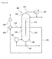
- FIG. 1 is an exemplary diagram showing a device for preparing an alkanol.
- a device including a distillation column 100 into which a raw material 110 including a compound represented by the following Formula 1 flows is provided.
- Formula 1 [Formula 1] R-OH
- R represents an alkyl group, for example, an alkyl group having 1 to 20 carbon atoms, 1 to 16 carbon atoms, 1 to 12 carbon atoms, or 1 to 8 carbon atoms.
- the alkyl group may have a linear, branched, or cyclic structure, and may be optionally substituted with one or more substituents, when necessary.
- the component of Formula 1 may be an octanol, for example, 2-ethylhexanol.
- the distillation column 100 may be a divided-wall distillation column 100.
- the divided-wall distillation column 100 is generally a device designed to distill the raw material 110 including three components having a low boiling point, a middle boiling point, and a high boiling point.
- the divided-wall distillation column 100 is generally a device similar to a Petlyuk distillation column in a thermodynamic aspect.
- the Petlyuk distillation column has a structure in which a pre-fractionator and a main column are thermally integrated.
- the distillation column is designed so that a low boiling point material and a high boiling point material can be primarily separated at the pre-fractionator, components present in column top and column bottom regions of the pre-fractionator can flow into a feed stage of the main column, and the low boiling point material, the middle boiling point material and the high boiling point material can be separated at the main column.
- the divided-wall distillation column 100 is configured to install a divided wall 101 in the column so as to integrate the pre-fractionator into the main column.
- the divided-wall distillation column 100 may, for example, have a structure as shown in FIG. 1.
- FIG. 1 shows an exemplary divided-wall distillation column 100.
- the exemplary distillation column 100 may have a structure in which an inner part of the distillation column 100 is divided by a divided wall 101 and which has a condenser 102 and a reboiler 103 formed respectively in upper and lower portions thereof.
- the inner part of the divided-wall distillation column 100 may be imaginarily divided by dotted lines shown in FIG.
- the raw material feed region 106 may be divided into an upper feed region 1061 and a lower feed region 1062, and the product outflow region 107 may be divided into an upper outflow region 1071 and a lower outflow region 1072.
- upper and lower feed regions may refer to upper and lower regions, respectively, when the raw material feed region 106, that is, a space in a side of the divided-wall distillation column 100 in which the raw material 110 is fed in spaces divided by the divided wall 101 in the structure of the divided-wall distillation column 100, is bisected in a longitudinal direction of the distillation column 100.
- upper and lower outflow regions may refer to upper and lower regions, respectively, when the product outflow region 107, that is, a space in a side of the divided-wall distillation column 100 from which a product flows out in the spaces divided by the divided wall 101 in the inner part of the divided-wall distillation column 100.
- the divided-wall distillation column 100 that may be used in a process of distilling an alkanol are not particularly limited.
- the divided-wall distillation column 100 having a typical structure as shown in FIG. 1 may be used, or a distillation column in which the position and shape of the divided wall 101 in the distillation column are designed to be altered may also be used in consideration of refining efficiency.
- the plate number and internal diameter of the distillation column are not particularly limited, and may, for example, determined based on a theoretical plate number derived from a distillation curve plotted in consideration of compositions of the raw material 110.
- the raw material 110 may be introduced into the raw material feed region 106 of the divided-wall distillation column 100, as shown in FIG. 1 .
- the raw material 110 introduced into the raw material feed region 106 may be separated into a product stream 140, a column bottom stream 130, and a column top stream 120 to flow out therefrom.
- the column top stream 120 that is a component having a relatively low boiling point in the components of the raw material 110 is discharged from the column top region 104 of the divided-wall distillation column 100, and the column bottom stream 130 having a relatively high boiling point in the components of the raw material 110 is discharged from the column bottom region 105 of the divided-wall distillation column 100.
- the component having a middle boiling point may be discharged as the product stream 140 from the product outflow region 107.
- the raw material 110 including an octanol for example 2-ethylhexanol
- a low boiling point stream that is a component having a relatively low boiling point in components of the raw material 110 is discharged from the column top region 104 of the divided-wall distillation column 100
- a high boiling point stream that is a component having a relatively high boiling point in the components of the raw material 110 is separated and discharged from the column bottom region 105 of the divided-wall distillation column 100.
- the product stream 140 including an octanol, such as 2-ethylhexanol, which is a component having a relatively middle boiling point in the components of the raw material 110 may be discharged from the product outflow region 107, for example, an upper outflow region 1071 or a lower outflow region 1072, of the divided-wall distillation column 100.
- the column top stream 120 in the divided-wall distillation column 100 passes through the condenser 102 as described above, and some of the column top stream 120 may be refluxed to the column top region 104 of the distillation column, and the rest of the column top stream 120 may be stored as a product.
- the term "low boiling point stream” refers to a stream in which the low boiling point component having a relatively low boiling point discharged from the column top region 104 of the divided-wall distillation column 100 is rich
- the term "high boiling point stream” refers to a stream in which the high boiling point component having a relatively high boiling point discharged from the column bottom region 105 of the divided-wall distillation column 100 is rich.
- the term “product stream” refers to a product flowing out from the product outflow region 107 of the divided-wall distillation column 100, that is, a stream in which the middle boiling point component is rich.
- the term “rich stream” refers to a stream in which the low boiling point component included in the stream discharged from the column top region 104, the high boiling point component included in the stream discharged from the column bottom region 105, and the middle boiling point component included in the stream discharged from the product outflow region 107 have higher contents than the low boiling point component, the high boiling point component and the middle boiling point component included in the raw material 110, respectively.
- the rich stream may refer to a stream in which each of the low boiling point component, the high boiling point component, and the low boiling point component included in the stream discharged from the column top region 104, the column bottom region 105, and the product outflow region 107 has a content of 50% by weight or more, 80% by weight or more, 90% by weight or more, 95% by weight or more, or 99% by weight or more.
- the low boiling point stream and the column top stream 120 may be used synonymously
- the high boiling point stream and the column bottom stream 130 may be used synonymously
- the middle boiling point stream and the product stream 140 may be used synonymously.
- the preparing device may include a heat exchanger.
- some or all of at least one stream selected from the group consisting of the column top stream 120, the column bottom stream 130, and the product stream 140 may exchange heat. Therefore, a high-purity alkanol may be separated and refined while minimizing the loss of energy caused during a process of preparing an alkanol, for example, 2-ethylhexanol.
- some or all of the column top stream 120 may exchange heat with water, or some or all of at least one stream selected from the group consisting of the column top stream 120, the column bottom stream 130, and the product stream 140 may exchange heat with the raw material 110 flowing into the raw material feed region 106.
- FIG. 2 is a diagram showing a device for preparing an alkanol according to a first exemplary embodiment of the present application.
- the heat exchanger may be a heat exchanger 300 for column top stream, as shown in FIG. 2 .
- the heat exchanger 300 for column top stream may be arranged to be directly or indirectly coupled to a pipe through which the low boiling point stream in the preparing device flows.
- the heat exchanger 300 for column top stream may be preferably directly coupled to the pipe through which the low boiling point stream in the distillation column 100 flows.
- the heat exchanger 300 for column top stream may, for example, be arranged in a front stage of the condenser 102 so that the column top stream 120 sequentially passes through the heat exchanger 300 and the condenser 102. For example, after the low boiling point stream sequentially passes through the heat exchanger 300 for column top stream, and the condenser 102, some of the low boiling point stream passing through the condenser 102 may be refluxed to the distillation column 100.
- the preparing device further include a heat exchanger 300 for column top stream as described above, the low boiling point stream in the divided-wall distillation column 100 passes through the heat exchanger 300 for column top stream. In this case, heat is applied to the heat exchanger 300 for column top stream. Therefore, the low boiling point stream is refluxed to the divided-wall distillation column 100 at a relatively low temperature. In this case, the cost spent in a concentration process in which the condenser 102 is used may be cut by reducing the quantity of energy used in the concentration process before the low boiling point stream is refluxed to the divided-wall distillation column 100.
- the heat exchanger 300 for column top stream may be a heat exchanger configured to produce steam.
- the heat exchanger 300 for column top stream may exchange heat with water so as to produce high-temperature steam.
- the high-temperature steam produced in the heat exchanger 300 may, for example, used as a heat source in a vaporizer, a stripping column, or an isomer column used in a process of preparing an octanol.
- the low boiling point stream refluxed to the distillation column 100 after the heat exchange is completed may have a reflux ratio of 1 to 100.
- the reflux ratio of the low boiling point stream may be preferably in a range of 5 to 70, more preferably 18.5 to 25.5.
- the reflux ratio of the low boiling point stream is adjusted in a range of 100 or less, preferably 70 or less, and most preferably 25.5 or less, as described above, the energy consumed to reflux the column top stream refluxed to the distillation column 100 in the column top stream 120 which has a temperature of 100 to 120 °C and is heat-exchanged with water by means of the heat exchanger 300 for column top stream may be minimized, and some of the column top stream 120 may be produced as a high-purity product at the same time.
- 2-ethylhexanol having a high purity, for example, a purity of 99.0 % or more may also be produced from the product stream by adjusting the reflux ratio in a range of 5 to 70, preferably 18 to 25.5.
- the term "reflux ratio" used herein refers to a ratio of a flow rate of a refluxed stream with respect to an outflow rate of a stream flowing out from the distillation column 100.
- FIG. 3 is a diagram showing an exemplary preparing device according to a second exemplary embodiment of the present application.
- a heat exchanger 310 for column top stream may be a heat exchanger configured to preheat a raw material.
- the exemplary preparing device as the low boiling point stream passes through the heat exchanger 310 configured to preheat a raw material for column top stream, some or all of the low boiling point stream flowing out from the column top region 104 may exchange heat with the raw material 110 flowing into the raw material feed region 106 so as to preheat the raw material 110.
- the raw material 110 flowing into the divided-wall distillation column 100 may be preheated when the low boiling point stream exchanges heat with the raw material 110 flowing into the low-temperature divided-wall distillation column 100.
- the energy consumed in a heater configured to raise a temperature of the raw material 110 flowing into the divided-wall distillation column 100, or a reboiler 103 configured to heat the column bottom stream 130 discharged from the column bottom region 105 of the divided-wall distillation column 100 may be reduced.
- the cost spent in a concentration process in which the condenser 102 is used may be cut by reducing the quantity of cooling water used in the concentration process before the low boiling point stream in the divided-wall distillation column 100 is refluxed to the column top region 104 of the divided-wall distillation column 100.
- the low boiling point stream refluxed to the distillation column 100 after the heat exchange is completed may have a reflux ratio of 1 to 100.
- the reflux ratio of the low boiling point stream may be preferably in a range of 5 to 70, more preferably 8.4 to 17.3.
- the reflux ratio of the low boiling point stream is adjusted in a range of 100 or less, preferably 70 or less, and most preferably 17.3 or less, as described above, the energy consumed to reflux the column top stream refluxed to the distillation column 100 in the column top stream 120 which has a temperature of 90 to 100 °C and is heat-exchanged with the raw material by means of the heat exchanger 300 for column top stream may be minimized, and some of the column top stream 120 may be produced as a high-purity product at the same time.
- 2-ethylhexanol having a high purity for example, a purity of 99.0 % or more, may also be produced from the product stream by adjusting the reflux ratio in a range of 5 to 70, preferably 8.4 to 17.3.
- the heat exchanger may be a heat exchanger for product stream, and, according to one exemplary embodiment, may be a heat exchanger configured to preheat a raw material.
- FIG. 4 is a diagram showing an exemplary preparing device according to a third exemplary embodiment of the present application.
- the exemplary preparing device as the product stream 140 including the middle boiling point stream passes through a heat exchanger 400 configured to preheat a raw material for product stream, some or all of the middle boiling point stream flowing out from the product outflow region 107 may exchange heat with the raw material 110 flowing out from the raw material feed region 106 so as to preheat the raw material 110.
- some or all of the product stream 140 flowing out from the product outflow region 107 may exchange heat with the raw material 110 flowing into the raw material feed region 106 so as to preheat the raw material 110.
- the high-temperature product stream 140 discharged from the product outflow region 107 of the divided-wall distillation column 100 may flow through the pipe so that the product stream 140 can exchange heat with the raw material 110 flowing into the divided-wall distillation column 100 in the heat exchanger 400 for product stream, and then the product stream 140 may be produced as a product while sequentially passing through a cooler 600.
- the raw material 110 flowing into the divided-wall distillation column 100 may be preheated when the product stream 140 exchanges heat with the raw material 110 flowing into the low-temperature divided-wall distillation column 100.
- the energy consumed in a heater configured to raise a temperature of the raw material 110 flowing into the divided-wall distillation column 100, or a reboiler 103 configured to heat the column bottom stream 130 discharged from the column bottom region 105 of the divided-wall distillation column 100 may be reduced.
- the cost spent in a concentration process in which the cooler 600 is used may be cut by reducing the quantity of cooling water used in the concentration process before the stream including the octanol is produced as a product.
- the low boiling point stream refluxed to the distillation column 100 after the heat exchange is completed, that is, the column top stream may have a reflux ratio of 1 to 100.
- the reflux ratio of the column top stream may be preferably in a range of 5 to 70, more preferably 15.2 to 18.5.
- the reflux ratio of the column top stream is adjusted in a range of 100 or less, preferably 70 or less, and most preferably 18.5 or less, as described above, the energy consumed to cool the product stream 140 flowing into a storage tank in the column top stream 120 which has a temperature of 40 to 100 °C and is heat-exchanged with the raw material by means of the heat exchanger 400 for product stream may be minimized, and some of the column top stream 120 may be produced as a high-purity product at the same time.
- 2-ethylhexanol having a high purity may also be produced from the product stream 140 by adjusting the reflux ratio in a range of 5 to 70, preferably 15.2 to 18.5.
- the preparing device may include both of the heat exchanger 300 for column top stream and the heat exchanger 400 for product stream.
- the heat exchanger 300 for column top stream may be a heat exchanger configured to produce steam.
- the column top stream 120 may exchange heat with water to produce steam.
- the steam produced in the heat exchanger 300 configured to produce steam for column top stream may be used in a heating process in which the reboiler 103 is used before the raw material 110 flows into the divided-wall distillation column 100, or may be used as a heat source in a vaporizer, a stripping column or an isomer column used in a process of preparing an octanol.
- energy-saving and cost-cutting effects by the piping system and the heat exchanger 400 for product stream, both of which are formed to exchange heat with the raw material 110 may be achieved, as described above.
- the divided-wall distillation column 100 includes the heat exchanger for column top stream
- an effect of cutting the cost consumed in a concentration process in which the condenser 102 is used may be further achieved by reducing the quantity of cooling water used in the concentration process before some of the low boiling point stream in the divided-wall distillation column 100 is refluxed to the column top region 104 of the divided-wall distillation column 100, as described above.
- the low boiling point stream refluxed to the distillation column 100 after the heat exchange is completed may have a reflux ratio of 1 to 100.
- the reflux ratio of the low boiling point stream may be preferably in a range of 5 to 70, more preferably 7.2 to 16.5.
- the energy consumed to reflux the column top stream refluxed to the distillation column 100 in the column top stream 120 which has a temperature of 40 to 120 °C and exchanges heat by means of the heat exchanger 300 for column top stream may be minimized, and some of the column top stream may be simultaneously produced as a high-purity product by adjusting the reflux ratio in a range of 100 or less, preferably 70 or less, and most preferably 16.5 or less, as described above.
- 2-ethylhexanol having a high purity may also be produced from the product stream 140 by adjusting the reflux ratio in a range of 5 to 70, preferably 7.2 to 16.5.
- the exemplary device for preparing an alkanol may also include the heat exchanger 310 configured to preheat a raw material for column top stream, and the heat exchanger 400 for product stream.
- the raw material 110 flowing into the divided-wall distillation column 100 may be preheated when the low boiling point stream exchanges heat with the low-temperature raw material 110 flowing into the divided-wall distillation column 100 using the heat exchanger 310 configured to preheat a raw material for column top stream.
- the raw material may be further preheated by means of the heat exchanger 400 for product stream.
- the energy consumed in a heater configured to raise a temperature of the raw material 110 flowing into the divided-wall distillation column 100, or a reboiler 103 configured to heat the column bottom stream 130 discharged from the column bottom region 105 of the divided-wall distillation column 100 may be reduced.
- the cost spent in a concentration process in which the condenser 102 is used may be cut by reducing the quantity of cooling water used in the concentration process before the low boiling point stream in the divided-wall distillation column 100 is refluxed to the column top region 104 of the divided-wall distillation column 100.
- the temperature of the product stream may be regulated so that a difference in temperature ( ⁇ T min ) between the product stream 140 and the raw material preheated by means of the heat exchanger 310 configured to preheat a raw material for column top stream is greater than or equal to 5 °C.
- the difference in temperature ( ⁇ T min ) may be regulated by pressurizing or depressurizing the pipe through which the product stream flows.
- the low boiling point stream refluxed to the distillation column 100 after the heat exchange is completed may also have a reflux ratio of 1 to 100.
- the reflux ratio of the low boiling point stream may be preferably in a range of 5 to 70, more preferably 6.8 to 16.1.
- the energy consumed to reflux the column top stream 120 which exchanges heat by means of the heat exchanger 310 for column top stream and is refluxed to the distillation column 100 at a temperature of 40 to 120 °C, may be minimized, and some of the column top stream may be simultaneously produced as a high-purity product by adjusting the reflux ratio in a range of 100 or less, preferably 16.1 or less, as described above.
- the heat exchanger may be a heat exchanger for column bottom stream, and, according to one exemplary embodiment, may be a heat exchanger configured to preheat a raw material.
- FIG. 5 is a diagram showing an exemplary preparing device according to a fourth exemplary embodiment of the present application.
- some of the high boiling point stream flowing out from the column bottom region 105 is refluxed to the column bottom region 105 through the reboiler, and some or all of the rest of the high boiling point stream may flows through the pipe so that the high boiling point stream can exchange heat with the raw material 110 flowing into the divided-wall distillation column 100 in a heat exchanger 500 configured to preheat a raw material for column bottom stream, and the high boiling point stream may be produced as a article while sequentially passing through a cooler 601.
- the heat exchanger 500 configured to preheat a raw material for column bottom stream
- some or all of the high boiling point stream flowing out from the column bottom region 105 may exchange heat with the raw material 110 flowing into the raw material feed region 106 so as to preheat the raw material 110.
- the raw material 110 flowing into the divided-wall distillation column 100 may be preheated when the high boiling point stream exchanges heat with the low-temperature raw material 110 flowing into the divided-wall distillation column 100 using the heat exchanger 500 configured to preheat a raw material for column bottom stream.
- the cost spend in a concentration process in which the condenser 102 is used may be cut by reducing the quantity of cooling water used in the concentration process before the low boiling point stream in the divided-wall distillation column 100, that is, the column top stream 120, is refluxed to the column top region 104 of the divided-wall distillation column 100. Further, the cost spend in a cooling process in which the cooler 601 is used may be cut by reducing the quantity of cooling water used in the cooling process before the high boiling point stream is produced as a product. In this case, the low boiling point stream refluxed to the distillation column 100 after the heat exchange is completed, the column top stream 120 may also have a reflux ratio of 1 to 100.
- the reflux ratio of the column top stream 120 may be preferably in a range of 5 to 70, more preferably 16.6 to 19.8.
- the reflux ratio of the column top stream 120 is adjusted in a range of 100 or less, preferably 70 or less, and most preferably, 19.8 or less, the energy consumed to cool the column bottom stream 130 flowing into a storage tank in the column bottom stream 130 which has a temperature of 40 to 100 °C and exchanges heat with the raw material by means of the heat exchanger 500 for column bottom stream may be minimized, and some of the column top stream 120 may be produced as a high-purity product at the same time.
- 2-ethylhexanol having a high purity may also be produced from the product stream 140 by adjusting the reflux ratio in a range of 5 to 70, preferably 16.6 to 19.8.
- the preparing device may include the heat exchanger 500 configured to preheat a raw material for column bottom stream, and the heat exchanger 400 for product stream.
- the raw material 110 flowing into the divided-wall distillation column 100 may be preheated when the product stream exchanges heat with the raw material 110 flowing into the low-temperature divided-wall distillation column 100 using the heat exchanger 400 configured to preheat a raw material for product stream.
- the raw material 110 may be further preheated by means of the heat exchanger 500 for column bottom stream.
- the energy consumed in a heater configured to raise a temperature of the raw material 110 flowing into the divided-wall distillation column 100, or a reboiler 103 configured to heat the column bottom stream 130 discharged from the column bottom region 105 of the divided-wall distillation column 100 may be reduced.
- the cost spent in a concentration process in which the condenser 102 is used may be cut by reducing the quantity of cooling water used in the concentration process before the low boiling point stream in the divided-wall distillation column 100 is refluxed to the column top region 104 of the divided-wall distillation column 100.
- the temperature of the column bottom stream 130 may be regulated so that a difference in temperature ( ⁇ T min ) between the column bottom stream and the raw material preheated through the heat exchanger 400 configured to preheat a raw material for product stream is greater than or equal to 5 °C.
- the difference in temperature ( ⁇ T min ) may be regulated by pressurizing or depressurizing the pipe through which the column bottom stream 130 flows.
- the low boiling point stream refluxed to the distillation column 100 after the heat exchange is completed that is, the column top stream 120, may also have a reflux ratio of 1 to 100.
- the reflux ratio of the low boiling point stream may be preferably in a range of 5 to 70, more preferably 12.1 to 17.0.
- 2-ethylhexanol having a high purity for example, a purity of 99.0 % or more, may also be produced from the product stream 140 by adjusting the reflux ratio in a range of 100 or less, preferably 17.0 or less, as described above.
- the preparing device may also include the heat exchanger 310 configured to preheat a raw material for column top stream, and the heat exchanger 500 configured to preheat a raw material for column bottom stream.
- the raw material 110 flowing into the divided-wall distillation column 100 may be preheated when the column top stream 120 in the divided-wall distillation column exchanges heat with the raw material 110 flowing into the low-temperature divided-wall distillation column 100 using the heat exchanger 310 configured to preheat a raw material for column top stream.
- the raw material may be further preheated by means of the heat exchanger 500 for column bottom stream.
- Still another exemplary embodiment of the present application provides a device for preparing an alkanol, which includes a divided-wall distillation column provided with a condenser, a reboiler, a heat exchanger configured to produce steam for column top stream, a heat exchanger configured to preheat a raw material, and a divided wall.
- FIG. 6 is a diagram showing an exemplary device for preparing an alkanol according to a fifth exemplary embodiment of the present application.
- the device for preparing an alkanol may include a divided-wall distillation column 100 which is provided with a condenser 102, a reboiler 103, and a divided wall 101, and is divided into a raw material feed region 106, a product outflow region 107, a column top region 104, and a column bottom region 105.
- the divided-wall distillation column 100 may include a heat exchanger 300 for column top stream, and a heat exchanger configured to preheat a raw material.
- the raw material 110 including an octanol may flow in the raw material feed region 106 of the divided-wall distillation column 100, and the raw material 110 flowing into the material feed region 106 may be separated into a product stream 140, a high boiling point stream, and a low boiling point stream to flow out therefrom.
- the high boiling point stream may also flow out from the column bottom region 105, and some of the high boiling point stream may be refluxed to the distillation column 100 through the reboiler 103.
- the low boiling point stream may flow out from the column top region 104, and pass through the condenser 102, and some of the stream passing through the condenser 102 may be refluxed to the distillation column 100.
- the heat exchanger 300 for column top stream may be a heat exchanger configured to produce steam.
- the low boiling point stream in the divided-wall distillation column 100 may exchange heat with water so as to produce steam, as described above.
- the steam produced in the heat exchanger 300 for column top stream may be used in a heating process in which the heater is used before the raw material 110 flows into the divided-wall distillation column 100, or may be used as a heat source in a vaporizer, a stripping column or an isomer column used in a process of preparing an octanol.
- energy-saving and cost-cutting effects by the piping system and the heat exchanger 400 for product stream, both of which are formed to perform the heat exchange with the raw material 110 may be achieved, as described above.
- an effect of cutting the cost consumed in a concentration process in which the condenser 102 is used may be further achieved by reducing the quantity of cooling water used in the concentration process before some of the low boiling point stream in the divided-wall distillation column 100 is refluxed to the column top region 104 of the divided-wall distillation column 100, as described above.
- the divided-wall distillation column includes a heat exchanger configured to preheat a raw material.
- a heat exchanger configured to preheat a raw material
- some or all of the column bottom stream 130 or the product stream 140 exchanges heat with the raw material flowing into the raw material feed region so as to heat the raw material.
- the heat exchanger configured to preheat a raw material may be a heat exchanger 400 for product stream, as shown in FIG. 6 .
- the heat exchanger 400 for product stream may be arranged to be directly or indirectly coupled to a pipe through which the product stream 140 in the preparing device flows.
- the heat exchanger 400 for product stream may be preferably directly coupled to the pipe through which the product stream 140 in the distillation column 100 flows.
- the raw material 110 flowing into the divided-wall distillation column 100 may be preheated to raise the temperature of the raw material 110 when the product stream 140 exchanges heat with the low-temperature raw material 110 flowing into the divided-wall distillation column 100. Therefore, the energy consumed in a heater configured to raise a temperature of the raw material 110 flowing into the divided-wall distillation column 100, or a reboiler 103 configured to heat the column bottom stream 130 discharged from the column bottom region 105 of the divided-wall distillation column 100 may be reduced. Further, the cost spent in a cooling process in which the cooler 600 is used may be cut by reducing the quantity of cooling water used in the cooling process before the stream including the octanol is produced as a product.
- the column top stream refluxed to the distillation column 100 after the heat exchange is completed may also have a reflux ratio of 1 to 100.
- the reflux ratio of the column top stream may be preferably in a range of 5 to 70, more preferably 7.2 to 16.5.
- the energy consumed to reflux the column top stream 120 which exchanges heat by means of the heat exchanger for column top stream and is refluxed to the distillation column 100 at a temperature of 40 to 120 °C, may be minimized, and some of the column top stream 120 may be simultaneously produced as a high-purity, product by adjusting the reflux ratio in a range of 100 or less, preferably 16.5 or less, as described above.
- 2-ethylhexanol having a high purity may also be produced from the product stream 140 by adjusting the reflux ratio in a range of 5 to 70, preferably 7.2 to 16.5.
- the divided-wall distillation column 100 may also include the heat exchanger 300 for column top stream, and a heat exchanger configured to preheat a raw material.
- the heat exchanger configured to preheat a raw material may be a heat exchanger for column bottom stream.
- FIG. 7 is a diagram showing an exemplary device for preparing an alkanol according to a sixth exemplary embodiment of the present application.
- the heat exchanger 500 for column bottom stream may be arranged to be directly or indirectly coupled to a pipe through which the column bottom stream 130 in the preparing device flows.
- the heat exchanger 500 for column bottom stream may be preferably directly coupled to the pipe through which the column bottom stream 130 in the distillation column 100 flows.
- the raw material 110 flowing into the divided-wall distillation column 100 may be preheated to raise the temperature of the raw material 110 when the column bottom stream 130 exchanges heat with the raw material 110 flowing into the divided-wall distillation column 100. Therefore, the energy consumed in a heater configured to raise a temperature of the raw material 110 flowing into the divided-wall distillation column 100, or a reboiler 103 configured to heat the column bottom stream 130 discharged from the column bottom region 105 of the divided-wall distillation column 100 may be reduced.
- the cost spent in a cooling process in which the cooler 601 is used may be cut by reducing the quantity of cooling water used in the cooling process before the high boiling point stream is produced as a product.
- the column top stream 120 refluxed to the distillation column 100 after the heat exchange is completed may also have a reflux ratio of 1 to 100.
- the reflux ratio of the column top stream 120 may be preferably in a range of 5 to 70, more preferably 8.1 to 17.1.
- 2-ethylhexanol having a high purity may also be produced from the product stream 140 by adjusting the reflux ratio in a range of 100 or less, preferably 70 or less, and most preferably, 17.1 or less, as described above.
- Another aspect of the present application provides a method of preparing an alkanol.
- the preparing method may be performed using the above-described device for preparing an alkanol.
- the exemplary method may include allowing the raw material 110 including a compound represented by the following Formula 1, for example, an octanol such as 2-ethylhexanol, to flow into the divided-wall distillation column 100, and distilling the raw material 110 flowing into the divided-wall distillation column 100 and separating the raw material into a product stream 140, a column bottom stream 130, and a column top stream 120 to flow out therefrom.
- Formula 1 R-OH
- R represents an alkyl group.
- some or all of the column top stream 120 may exchange heat with raw material 110 flowing into the distillation column 100 or water outside the distillation column 100.
- the raw material 110 flowing into the divided-wall distillation column 100 may be preheated when some or all of the column top stream 120 exchanges heat with the raw material 110 flowing into the low-temperature divided-wall distillation column 100. Therefore, the energy consumed in a heater configured to raise a temperature of the raw material 110 flowing into the divided-wall distillation column 100, or a reboiler 103 configured to heat the column bottom stream 130 discharged from the column bottom region 105 of the divided-wall distillation column 100 may be reduced.
- the cost spent in a concentration process in which the condenser 102 is used may be cut by reducing the quantity of cooling water used in the concentration process before the column top stream 120 in the divided-wall distillation column 100 is refluxed to the column top region 104 of the divided-wall distillation column 100.
- the reflux ratio of the column top stream 120 refluxed to the distillation column 100 after the heat exchange is completed may be adjusted in a range of 1 to 100.
- the reflux ratio of the column top stream 120 may be preferably adjusted in a range of 5 to 70, more preferably 8.4 to 17.3.
- a high-temperature steam may be produced when some or all of the column top stream 120 exchanges heat with water outside the distillation column 100.
- the produced high-temperature steam may be used as a heat source in a vaporizer, a stripping column or an isomer column used in a process of preparing an octanol.
- the reflux ratio of the column top stream 120 refluxed to the distillation column 100 after the heat exchange is completed may be adjusted in a range of 1 to 100.
- the reflux ratio of the column top stream 120 may be preferably adjusted in a range of 5 to 70, more preferably 18.5 to 25.5.
- some or all of the product stream 140 or the column bottom stream may also further exchange heat with the raw material 110 flowing into the distillation column 100.
- the column top stream 120 may exchange heat with water outside the distillation column 100, and some or all of the product stream 140 may exchange heat with the raw material 110 flowing into the distillation column 100.
- the reflux ratio of the column top stream 120 refluxed to the distillation column 100 after the heat exchange is completed may be adjusted in a range of 1 to 100.
- the reflux ratio of the column top stream may be preferably adjusted in a range of 5 to 70, more preferably 7.2 to 16.5.
- some or all of the column top stream 120 and some or all of the product stream 140 may exchange heat with the raw material 110 flowing into the distillation column 100.
- the reflux ratio of the column top stream 120 refluxed to the distillation column 100 after the heat exchange is completed may be adjusted in a range of 1 to 100.
- the reflux ratio of the column top stream 120 may be preferably adjusted in a range of 5 to 70, more preferably 8.4 to 17.3.
- some or all of the column top stream 120 may also exchange heat with water outside the distillation column 100, and some or all of the column bottom stream may exchange heat with the raw material 110 flowing into the distillation column 100.
- the reflux ratio of the column top stream 120 refluxed to the distillation column 100 after the heat exchange is completed may be adjusted in a range of 1 to 100.
- the reflux ratio of the column top stream 120 may be preferably adjusted in a range of 5 to 70, more preferably 8.1 to 17.1.
- some or all of the column top stream 120 and some or all of the column bottom stream 130 may exchange heat with the raw material 110 flowing into the distillation column 100.
- the reflux ratio of the column top stream 120 refluxed to the distillation column 100 after the heat exchange is completed may be adjusted in a range of 1 to 100.
- the reflux ratio of the column top stream 120 may be preferably adjusted in a range of 5 to 70, more preferably 9.1 to 17.6.
- some or all of the product stream 140 and some or all of the column bottom stream 130 may also exchange heat with the raw material 110 flowing into the distillation column 100.
- the reflux ratio of the column top stream 120 refluxed to the distillation column 100 after the heat exchange is completed may be adjusted in a range of 1 to 100.
- the reflux ratio of the column top stream 120 may be preferably adjusted in a range of 5 to 70, more preferably 12.1 to 17.0.
- the column top stream 120 may exchange heat with water outside the distillation column 100, and some or all of the column top stream 120 and some or all of the product stream 140 may exchange heat with the raw material 110 flowing into the distillation column 100.
- the reflux ratio of the column top stream 120 refluxed to the distillation column 100 after the heat exchange is completed may be adjusted in a range of 1 to 100.
- the reflux ratio of the column top stream 120 may be preferably adjusted in a range of 5 to 70, more preferably 7.2 to 16.5.
- the energy-saving and cost-cutting effects may be achieved when some or all of the column top stream 120 exchanges heat with the raw material 110 flowing into the distillation column 100 or water outside the distillation column 100.
- the raw material 110 flowing into the divided-wall distillation column 100 may be preheated to raise the temperature of the raw material 110.
- the energy consumed in a heater configured to raise a temperature of the raw material 110 flowing into the divided-wall distillation column 100, or a reboiler 103 configured to heat the column bottom stream 130 discharged from the column bottom region 105 of the divided-wall distillation column 100 may be reduced.
- the cost spent in a cooling process in which the cooler 600 or 601 is used may be cut by reducing the quantity of cooling water used in the cooling process before the middle boiling point stream and/or the high boiling point stream including the octanol is produced as a product.
- the raw material 110 flowing into the divided-wall distillation column 100 before the raw material 110 exchanges heat with the column top stream 120 or the product stream 140 in the divided-wall distillation column 100 may be maintained at a temperature of 30 °C to 50 °C, and the raw material 110 flowing into the divided-wall distillation column 100 after the raw material 110 exchanges heat with the column top stream 120 or the product stream 140 in the divided-wall distillation column 100 may be maintained at a temperature of 60 °C to 130 °C.
- a separation process may be performed, for example, while maintaining an upper portion of the divided-wall distillation column 100 at an operating pressure of 0.01 Kg/cm 2 to 10 Kg/cm 2 . Also, in the preparing method, the separation process may be performed, for example, while maintaining a lower portion of the divided-wall distillation column 100 at an operating pressure of 0.3 Kg/cm 2 to 11 Kg/cm 2 .
- energy saving can be promoted upon the manufacture of an alkanol by reducing the quantity of steam used in a reboiler of the device or the quantity of cooling water used in a condenser and a cooler, and the steam generated from a heat exchanger for column top stream can be used in a variety of fields.
- a high-purity alkanol can be prepared according to one exemplary embodiment of the present application.
- An octanol was prepared using a divided-wall distillation column, as shown in FIG. 2 . Specifically, a process of introducing a raw material including 2-ethylhexanol into the divided-wall distillation column and separating the raw material was performed. In this case, the conditions of such a process were set so that the operating pressure and operating temperature of a lower portion of the divided-wall distillation column were approximately 0.8 Kg/cm 2 and approximately 160 °C, respectively, and the operating pressure and operating temperature of an upper portion of the divided-wall distillation column were approximately 0.3 Kg/cm 2 and approximately 95 °C, respectively.
- An octanol was refined in the same manner as in Example 1, except that the low boiling point components and water discharged from the column top region of the divided-wall distillation column exchanged heat with a raw material introduced into the divided-wall distillation column, using a heat exchanger configured to preheat a raw material for column top stream, before the low boiling point components and water passed through the condenser, as shown in FIG. 3 .
- the reflux ratio of the column top stream in the divided-wall distillation column was set so that the column top stream had a reflux ratio of 8.4 to 17.3.
- An octanol was refined in the same manner as in Example 1, except that a product stream discharged from a product outflow region of the divided-wall distillation column exchanged heat with the raw material introduced into the divided-wall distillation column, using a heat exchanger configured to preheat a raw material for product stream, before the product stream flowed in a storage tank through a cooler, as shown in FIG. 4 .
- the reflux ratio of the column top stream in the divided-wall distillation column was set so that the column top stream had a reflux ratio of 15.2 to 18.5.
- An octanol was refined in the same manner as in Example 1, except that a portion of a column bottom stream discharged from a column bottom region of the divided-wall distillation column was refluxed to the column bottom region through the reboiler, and the rest of the column bottom stream exchanged heat with the raw material introduced into the divided-wall distillation column using a heat exchanger configured to preheat a raw material for column bottom stream, as shown in FIG. 5 .
- the reflux ratio of the column top stream in the divided-wall distillation column was set so that the column top stream had a reflux ratio of 16.6 to 19.8.
- An octanol was refined in the same manner as in Example 1, except that a product stream of octanol discharged from the product outflow region of the divided-wall distillation column exchanged heat with the raw material introduced into the divided-wall distillation column, using the heat exchanger configured to preheat a raw material for product stream, before the product stream of octanol passed through the cooler, and the low boiling point components and water discharged from the column top region of the divided-wall distillation column passed through the heat exchanger configured to produce steam for column top stream before the low boiling point components and water passed through the condenser, as shown in FIG. 6 .
- the reflux ratio of the column top stream in the divided-wall distillation column was set so that the column top stream had a reflux ratio of 7.2 to 16.5.
- An octanol was refined in the same manner as in Example 1, except that some of the column bottom stream discharged from the column bottom region of the divided-wall distillation column was refluxed to the column bottom region through the reboiler, the rest of the column bottom stream exchanged heat with the raw material introduced into the divided-wall distillation column using the heat exchanger configured to preheat a raw material for column bottom stream, and the low boiling point components and water discharged from the column top region of the divided-wall distillation column passed through the heat exchanger configured to produce steam for column top stream before the low boiling point components and water passed through the condenser, as shown in FIG. 7 .
- the reflux ratio of the column top stream in the divided-wall distillation column was set so that the column top stream had a reflux ratio of 8.1 to 17.1.
- An octanol was refined using a distillation column assembly in which general-type distillation columns were sequentially connected as shown in FIG. 8 .
- a stream discharged from a column top region of a first general-type distillation column passed through a condenser, and some of the stream was then refluxed to the general-type distillation column, and the rest of the stream was produced as a product.
- a stream discharged from a column bottom region of the first general-type distillation column passed through a reboiler, and some of the stream was then refluxed to the general-type distillation column, and the rest of the stream flowed in a second general-type distillation column.
- the reflux ratios of the column top streams of the first and second distillation columns were set so that the column top streams of the first and second distillation columns had a reflux ratio of 10 to 20 and 1 to 10, respectively.
Landscapes
- Chemical & Material Sciences (AREA)
- Organic Chemistry (AREA)
- Chemical Kinetics & Catalysis (AREA)
- Organic Low-Molecular-Weight Compounds And Preparation Thereof (AREA)
- Vaporization, Distillation, Condensation, Sublimation, And Cold Traps (AREA)
Abstract
Description
- The present application relates to a device and a method for preparing an alkanol.
- Alkanols such as octanols have been used for various applications in the chemical industry including, for example, perfumes, solvents for organic synthetic products, plasticizers, etc.
- For example, octanols may be manufactured by hydrogenating n-butylaldehyde. In the foregoing, the octanols manufactured by means of a hydrogenation reaction may be distilled through at least one distillation column. Thereafter, some or all of a stream may pass through a reboiler or a condenser during a distillation process to reflux the stream to the distillation column, thereby obtain high-purity octanols.
- The present application is directed to providing a device and a method for preparing an alkanol.
- One aspect of the present application provides a device for preparing an alkanol. The exemplary preparing device may include a distillation column. For example, the preparing device may be a distillation column assembly or a distillation system including the distillation column. When the device for preparing an alkanol is used, a high-purity alkanol may be separated and refined while minimizing the loss of energy caused during a process of preparing an alkanol. Hereinafter, the device will be described with reference to the accompanying drawings. However, it should be understood that the drawings are shown herein for illustration only, and are not construed as limiting the scope of the device according to one exemplary embodiment of the present application.
-
FIG. 1 is an exemplary diagram showing a device for preparing an alkanol. A device including adistillation column 100 into which araw material 110 including a compound represented by the following Formula 1 flows is provided.
[Formula 1] R-OH
- In Formula 1, R represents an alkyl group, for example, an alkyl group having 1 to 20 carbon atoms, 1 to 16 carbon atoms, 1 to 12 carbon atoms, or 1 to 8 carbon atoms. The alkyl group may have a linear, branched, or cyclic structure, and may be optionally substituted with one or more substituents, when necessary.
- According to one exemplary embodiment, the component of Formula 1 may be an octanol, for example, 2-ethylhexanol.
- In the foregoing, the
distillation column 100 may be a divided-wall distillation column 100. The divided-wall distillation column 100 is generally a device designed to distill theraw material 110 including three components having a low boiling point, a middle boiling point, and a high boiling point. The divided-wall distillation column 100 is generally a device similar to a Petlyuk distillation column in a thermodynamic aspect. The Petlyuk distillation column has a structure in which a pre-fractionator and a main column are thermally integrated. The distillation column is designed so that a low boiling point material and a high boiling point material can be primarily separated at the pre-fractionator, components present in column top and column bottom regions of the pre-fractionator can flow into a feed stage of the main column, and the low boiling point material, the middle boiling point material and the high boiling point material can be separated at the main column. In this case, the divided-wall distillation column 100 is configured to install adivided wall 101 in the column so as to integrate the pre-fractionator into the main column. - The divided-
wall distillation column 100 may, for example, have a structure as shown inFIG. 1. FIG. 1 shows an exemplary divided-wall distillation column 100. As shown inFIG. 1 , theexemplary distillation column 100 may have a structure in which an inner part of thedistillation column 100 is divided by a dividedwall 101 and which has acondenser 102 and areboiler 103 formed respectively in upper and lower portions thereof. Also, the inner part of the divided-wall distillation column 100 may be imaginarily divided by dotted lines shown inFIG. 1 , for example, divided into a columntop region 104 from which a low boiling point stream is discharged, acolumn bottom region 105 from which a high boiling point stream is discharged, a rawmaterial feed region 106 in which araw material 110 flows, and aproduct outflow region 107 from which a product flows out. Also, the rawmaterial feed region 106 may be divided into anupper feed region 1061 and alower feed region 1062, and theproduct outflow region 107 may be divided into anupper outflow region 1071 and alower outflow region 1072. In the foregoing, the term "upper and lower feed regions" may refer to upper and lower regions, respectively, when the rawmaterial feed region 106, that is, a space in a side of the divided-wall distillation column 100 in which theraw material 110 is fed in spaces divided by thedivided wall 101 in the structure of the divided-wall distillation column 100, is bisected in a longitudinal direction of thedistillation column 100. Also, the term "upper and lower outflow regions" may refer to upper and lower regions, respectively, when theproduct outflow region 107, that is, a space in a side of the divided-wall distillation column 100 from which a product flows out in the spaces divided by thedivided wall 101 in the inner part of the divided-wall distillation column 100. - Specific types of the divided-
wall distillation column 100 that may be used in a process of distilling an alkanol are not particularly limited. For example, the divided-wall distillation column 100 having a typical structure as shown inFIG. 1 may be used, or a distillation column in which the position and shape of the dividedwall 101 in the distillation column are designed to be altered may also be used in consideration of refining efficiency. Also, the plate number and internal diameter of the distillation column are not particularly limited, and may, for example, determined based on a theoretical plate number derived from a distillation curve plotted in consideration of compositions of theraw material 110. - To perform a refining process on the
raw material 110 including three components having a low boiling point, a middle boiling point, and a high boiling point, theraw material 110 may be introduced into the rawmaterial feed region 106 of the divided-wall distillation column 100, as shown inFIG. 1 . In the foregoing, theraw material 110 introduced into the rawmaterial feed region 106 may be separated into aproduct stream 140, acolumn bottom stream 130, and acolumn top stream 120 to flow out therefrom. For example, after theraw material 110 flows into the rawmaterial feed region 106 of the divided-wall distillation column 100, thecolumn top stream 120 that is a component having a relatively low boiling point in the components of theraw material 110 is discharged from the columntop region 104 of the divided-wall distillation column 100, and thecolumn bottom stream 130 having a relatively high boiling point in the components of theraw material 110 is discharged from thecolumn bottom region 105 of the divided-wall distillation column 100. Also, the component having a middle boiling point may be discharged as theproduct stream 140 from theproduct outflow region 107. According to one exemplary embodiment, when theraw material 110 including an octanol, for example 2-ethylhexanol, flows into the divided-wall distillation column 100, a low boiling point stream that is a component having a relatively low boiling point in components of theraw material 110 is discharged from the columntop region 104 of the divided-wall distillation column 100, and a high boiling point stream that is a component having a relatively high boiling point in the components of theraw material 110 is separated and discharged from thecolumn bottom region 105 of the divided-wall distillation column 100. Also, theproduct stream 140 including an octanol, such as 2-ethylhexanol, which is a component having a relatively middle boiling point in the components of theraw material 110 may be discharged from theproduct outflow region 107, for example, anupper outflow region 1071 or alower outflow region 1072, of the divided-wall distillation column 100. After thecolumn top stream 120 in the divided-wall distillation column 100 passes through thecondenser 102 as described above, and some of thecolumn top stream 120 may be refluxed to the columntop region 104 of the distillation column, and the rest of the columntop stream 120 may be stored as a product. Also, after the high boiling point stream in the divided-wall distillation column 100 passes through thereboiler 103, some of the high boiling point stream may be refluxed to thecolumn bottom region 105 of the distillation column, and the rest of the high boiling point stream may be produced as a product. In the foregoing, the term "low boiling point stream" refers to a stream in which the low boiling point component having a relatively low boiling point discharged from the columntop region 104 of the divided-wall distillation column 100 is rich, and the term "high boiling point stream" refers to a stream in which the high boiling point component having a relatively high boiling point discharged from thecolumn bottom region 105 of the divided-wall distillation column 100 is rich. Also, the term "product stream" refers to a product flowing out from theproduct outflow region 107 of the divided-wall distillation column 100, that is, a stream in which the middle boiling point component is rich. In the foregoing, the term "rich stream" refers to a stream in which the low boiling point component included in the stream discharged from the columntop region 104, the high boiling point component included in the stream discharged from thecolumn bottom region 105, and the middle boiling point component included in the stream discharged from theproduct outflow region 107 have higher contents than the low boiling point component, the high boiling point component and the middle boiling point component included in theraw material 110, respectively. For example, the rich stream may refer to a stream in which each of the low boiling point component, the high boiling point component, and the low boiling point component included in the stream discharged from the columntop region 104, thecolumn bottom region 105, and theproduct outflow region 107 has a content of 50% by weight or more, 80% by weight or more, 90% by weight or more, 95% by weight or more, or 99% by weight or more. In this specification, the low boiling point stream and thecolumn top stream 120 may be used synonymously, the high boiling point stream and thecolumn bottom stream 130 may be used synonymously, and the middle boiling point stream and theproduct stream 140 may be used synonymously. - According to one exemplary embodiment of the present application, the preparing device may include a heat exchanger.
- In the heat exchanger, some or all of at least one stream selected from the group consisting of the
column top stream 120, thecolumn bottom stream 130, and theproduct stream 140 may exchange heat. Therefore, a high-purity alkanol may be separated and refined while minimizing the loss of energy caused during a process of preparing an alkanol, for example, 2-ethylhexanol. According to one exemplary embodiment, in the heat exchanger, some or all of the columntop stream 120 may exchange heat with water, or some or all of at least one stream selected from the group consisting of thecolumn top stream 120, thecolumn bottom stream 130, and theproduct stream 140 may exchange heat with theraw material 110 flowing into the rawmaterial feed region 106. -
FIG. 2 is a diagram showing a device for preparing an alkanol according to a first exemplary embodiment of the present application. - According to one exemplary embodiment, the heat exchanger may be a
heat exchanger 300 for column top stream, as shown inFIG. 2 . In the foregoing, theheat exchanger 300 for column top stream may be arranged to be directly or indirectly coupled to a pipe through which the low boiling point stream in the preparing device flows. In a thermodynamic aspect, theheat exchanger 300 for column top stream may be preferably directly coupled to the pipe through which the low boiling point stream in thedistillation column 100 flows. Also, theheat exchanger 300 for column top stream may, for example, be arranged in a front stage of thecondenser 102 so that thecolumn top stream 120 sequentially passes through theheat exchanger 300 and thecondenser 102. For example, after the low boiling point stream sequentially passes through theheat exchanger 300 for column top stream, and thecondenser 102, some of the low boiling point stream passing through thecondenser 102 may be refluxed to thedistillation column 100. - Since the preparing device further include a
heat exchanger 300 for column top stream as described above, the low boiling point stream in the divided-wall distillation column 100 passes through theheat exchanger 300 for column top stream. In this case, heat is applied to theheat exchanger 300 for column top stream. Therefore, the low boiling point stream is refluxed to the divided-wall distillation column 100 at a relatively low temperature. In this case, the cost spent in a concentration process in which thecondenser 102 is used may be cut by reducing the quantity of energy used in the concentration process before the low boiling point stream is refluxed to the divided-wall distillation column 100. - According to one exemplary embodiment, the
heat exchanger 300 for column top stream may be a heat exchanger configured to produce steam. In the exemplary preparing device, as the low boiling point stream passes through theheat exchanger 300 configured to produce steam for column top stream, in theheat exchanger 300 for column top stream, some or all of the low boiling point stream flowing out from thecolumn top region 104 may exchange heat with water so as to produce high-temperature steam. The high-temperature steam produced in theheat exchanger 300 may, for example, used as a heat source in a vaporizer, a stripping column, or an isomer column used in a process of preparing an octanol. In this case, the low boiling point stream refluxed to thedistillation column 100 after the heat exchange is completed may have a reflux ratio of 1 to 100. In a thermodynamic aspect, the reflux ratio of the low boiling point stream may be preferably in a range of 5 to 70, more preferably 18.5 to 25.5. When the reflux ratio of the low boiling point stream is adjusted in a range of 100 or less, preferably 70 or less, and most preferably 25.5 or less, as described above, the energy consumed to reflux the column top stream refluxed to thedistillation column 100 in thecolumn top stream 120 which has a temperature of 100 to 120 °C and is heat-exchanged with water by means of theheat exchanger 300 for column top stream may be minimized, and some of thecolumn top stream 120 may be produced as a high-purity product at the same time. In this case, 2-ethylhexanol having a high purity, for example, a purity of 99.0 % or more, may also be produced from the product stream by adjusting the reflux ratio in a range of 5 to 70, preferably 18 to 25.5. The term "reflux ratio" used herein refers to a ratio of a flow rate of a refluxed stream with respect to an outflow rate of a stream flowing out from thedistillation column 100. -
FIG. 3 is a diagram showing an exemplary preparing device according to a second exemplary embodiment of the present application. - As shown in
FIG. 3 , aheat exchanger 310 for column top stream may be a heat exchanger configured to preheat a raw material. In the exemplary preparing device, as the low boiling point stream passes through theheat exchanger 310 configured to preheat a raw material for column top stream, some or all of the low boiling point stream flowing out from thecolumn top region 104 may exchange heat with theraw material 110 flowing into the rawmaterial feed region 106 so as to preheat theraw material 110. As described above, theraw material 110 flowing into the divided-wall distillation column 100 may be preheated when the low boiling point stream exchanges heat with theraw material 110 flowing into the low-temperature divided-wall distillation column 100. Therefore, the energy consumed in a heater configured to raise a temperature of theraw material 110 flowing into the divided-wall distillation column 100, or areboiler 103 configured to heat thecolumn bottom stream 130 discharged from thecolumn bottom region 105 of the divided-wall distillation column 100 may be reduced. Further, the cost spent in a concentration process in which thecondenser 102 is used may be cut by reducing the quantity of cooling water used in the concentration process before the low boiling point stream in the divided-wall distillation column 100 is refluxed to thecolumn top region 104 of the divided-wall distillation column 100. In this case, the low boiling point stream refluxed to thedistillation column 100 after the heat exchange is completed may have a reflux ratio of 1 to 100. In a thermodynamic aspect, the reflux ratio of the low boiling point stream may be preferably in a range of 5 to 70, more preferably 8.4 to 17.3. When the reflux ratio of the low boiling point stream is adjusted in a range of 100 or less, preferably 70 or less, and most preferably 17.3 or less, as described above, the energy consumed to reflux the column top stream refluxed to thedistillation column 100 in thecolumn top stream 120 which has a temperature of 90 to 100 °C and is heat-exchanged with the raw material by means of theheat exchanger 300 for column top stream may be minimized, and some of thecolumn top stream 120 may be produced as a high-purity product at the same time. In this case, 2-ethylhexanol having a high purity, for example, a purity of 99.0 % or more, may also be produced from the product stream by adjusting the reflux ratio in a range of 5 to 70, preferably 8.4 to 17.3. - According to still another exemplary embodiment of the present application, the heat exchanger may be a heat exchanger for product stream, and, according to one exemplary embodiment, may be a heat exchanger configured to preheat a raw material.
-
FIG. 4 is a diagram showing an exemplary preparing device according to a third exemplary embodiment of the present application. - As shown in
FIG. 4 , in the exemplary preparing device, as theproduct stream 140 including the middle boiling point stream passes through aheat exchanger 400 configured to preheat a raw material for product stream, some or all of the middle boiling point stream flowing out from theproduct outflow region 107 may exchange heat with theraw material 110 flowing out from the rawmaterial feed region 106 so as to preheat theraw material 110. For example, as theproduct stream 140 flowing out from theproduct outflow region 107 of the divided-wall distillation column 100 passes through theheat exchanger 400 for product stream, in theheat exchanger 400 for product stream, some or all of theproduct stream 140 flowing out from theproduct outflow region 107 may exchange heat with theraw material 110 flowing into the rawmaterial feed region 106 so as to preheat theraw material 110. By means of theheat exchanger 400 for product stream, the high-temperature product stream 140 discharged from theproduct outflow region 107 of the divided-wall distillation column 100 may flow through the pipe so that theproduct stream 140 can exchange heat with theraw material 110 flowing into the divided-wall distillation column 100 in theheat exchanger 400 for product stream, and then theproduct stream 140 may be produced as a product while sequentially passing through a cooler 600. As described above, theraw material 110 flowing into the divided-wall distillation column 100 may be preheated when theproduct stream 140 exchanges heat with theraw material 110 flowing into the low-temperature divided-wall distillation column 100. Therefore, the energy consumed in a heater configured to raise a temperature of theraw material 110 flowing into the divided-wall distillation column 100, or areboiler 103 configured to heat thecolumn bottom stream 130 discharged from thecolumn bottom region 105 of the divided-wall distillation column 100 may be reduced. Further, the cost spent in a concentration process in which the cooler 600 is used may be cut by reducing the quantity of cooling water used in the concentration process before the stream including the octanol is produced as a product. In this case, the low boiling point stream refluxed to thedistillation column 100 after the heat exchange is completed, that is, the column top stream, may have a reflux ratio of 1 to 100. In a thermodynamic aspect, the reflux ratio of the column top stream may be preferably in a range of 5 to 70, more preferably 15.2 to 18.5. When the reflux ratio of the column top stream is adjusted in a range of 100 or less, preferably 70 or less, and most preferably 18.5 or less, as described above, the energy consumed to cool theproduct stream 140 flowing into a storage tank in thecolumn top stream 120 which has a temperature of 40 to 100 °C and is heat-exchanged with the raw material by means of theheat exchanger 400 for product stream may be minimized, and some of thecolumn top stream 120 may be produced as a high-purity product at the same time. In this case, 2-ethylhexanol having a high purity, for example, a purity of 99.0 % or more, may also be produced from theproduct stream 140 by adjusting the reflux ratio in a range of 5 to 70, preferably 15.2 to 18.5. - According to one exemplary embodiment, the preparing device may include both of the
heat exchanger 300 for column top stream and theheat exchanger 400 for product stream. For example, when the preparing device includes both of theheat exchanger 300 for column top stream and theheat exchanger 400 for product stream, theheat exchanger 300 for column top stream may be a heat exchanger configured to produce steam. For example, as described above, as some or all of the low boiling point stream in the divided-wall distillation column 100, that is, thecolumn top stream 120, passes through theheat exchanger 300 configured to produce steam for column top stream, thecolumn top stream 120 may exchange heat with water to produce steam. For example, the steam produced in theheat exchanger 300 configured to produce steam for column top stream may be used in a heating process in which thereboiler 103 is used before theraw material 110 flows into the divided-wall distillation column 100, or may be used as a heat source in a vaporizer, a stripping column or an isomer column used in a process of preparing an octanol. Also, energy-saving and cost-cutting effects by the piping system and theheat exchanger 400 for product stream, both of which are formed to exchange heat with theraw material 110, may be achieved, as described above. In addition, when the divided-wall distillation column 100 includes the heat exchanger for column top stream, an effect of cutting the cost consumed in a concentration process in which thecondenser 102 is used may be further achieved by reducing the quantity of cooling water used in the concentration process before some of the low boiling point stream in the divided-wall distillation column 100 is refluxed to thecolumn top region 104 of the divided-wall distillation column 100, as described above. In this case, the low boiling point stream refluxed to thedistillation column 100 after the heat exchange is completed may have a reflux ratio of 1 to 100. In a thermodynamic aspect, the reflux ratio of the low boiling point stream may be preferably in a range of 5 to 70, more preferably 7.2 to 16.5. When the raw material whose heat exchange is completed by means of theheat exchanger 400 for product stream flows into the distillation column, and then flows out from the column top region at a temperature of 100 to 120 °C, the energy consumed to reflux the column top stream refluxed to thedistillation column 100 in thecolumn top stream 120 which has a temperature of 40 to 120 °C and exchanges heat by means of theheat exchanger 300 for column top stream may be minimized, and some of the column top stream may be simultaneously produced as a high-purity product by adjusting the reflux ratio in a range of 100 or less, preferably 70 or less, and most preferably 16.5 or less, as described above. In this case, 2-ethylhexanol having a high purity, for example, a purity of 99.0 % or more, may also be produced from theproduct stream 140 by adjusting the reflux ratio in a range of 5 to 70, preferably 7.2 to 16.5. - Although not shown, the exemplary device for preparing an alkanol according to one exemplary embodiment of the present application may also include the
heat exchanger 310 configured to preheat a raw material for column top stream, and theheat exchanger 400 for product stream. For example, theraw material 110 flowing into the divided-wall distillation column 100 may be preheated when the low boiling point stream exchanges heat with the low-temperatureraw material 110 flowing into the divided-wall distillation column 100 using theheat exchanger 310 configured to preheat a raw material for column top stream. When theraw material 110 is not sufficiently preheated, the raw material may be further preheated by means of theheat exchanger 400 for product stream. Therefore, the energy consumed in a heater configured to raise a temperature of theraw material 110 flowing into the divided-wall distillation column 100, or areboiler 103 configured to heat thecolumn bottom stream 130 discharged from thecolumn bottom region 105 of the divided-wall distillation column 100 may be reduced. Further, the cost spent in a concentration process in which thecondenser 102 is used may be cut by reducing the quantity of cooling water used in the concentration process before the low boiling point stream in the divided-wall distillation column 100 is refluxed to thecolumn top region 104 of the divided-wall distillation column 100. According to one exemplary embodiment, the temperature of the product stream may be regulated so that a difference in temperature (ΔTmin) between theproduct stream 140 and the raw material preheated by means of theheat exchanger 310 configured to preheat a raw material for column top stream is greater than or equal to 5 °C. For example, the difference in temperature (ΔTmin) may be regulated by pressurizing or depressurizing the pipe through which the product stream flows. In this case, the low boiling point stream refluxed to thedistillation column 100 after the heat exchange is completed may also have a reflux ratio of 1 to 100. In a thermodynamic aspect, the reflux ratio of the low boiling point stream may be preferably in a range of 5 to 70, more preferably 6.8 to 16.1. When the raw material whose heat exchange is completed by means of theheat exchanger 400 for product stream flows into the distillation column, and then flows out from thecolumn top region 104 at a temperature of 100 to 120 °C, the energy consumed to reflux thecolumn top stream 120, which exchanges heat by means of theheat exchanger 310 for column top stream and is refluxed to thedistillation column 100 at a temperature of 40 to 120 °C, may be minimized, and some of the column top stream may be simultaneously produced as a high-purity product by adjusting the reflux ratio in a range of 100 or less, preferably 16.1 or less, as described above. - According to still another exemplary embodiment of the present application, the heat exchanger may be a heat exchanger for column bottom stream, and, according to one exemplary embodiment, may be a heat exchanger configured to preheat a raw material.
-
FIG. 5 is a diagram showing an exemplary preparing device according to a fourth exemplary embodiment of the present application. - As shown in
FIG. 5 , in the exemplary preparing device, some of the high boiling point stream flowing out from thecolumn bottom region 105 is refluxed to thecolumn bottom region 105 through the reboiler, and some or all of the rest of the high boiling point stream may flows through the pipe so that the high boiling point stream can exchange heat with theraw material 110 flowing into the divided-wall distillation column 100 in aheat exchanger 500 configured to preheat a raw material for column bottom stream, and the high boiling point stream may be produced as a article while sequentially passing through a cooler 601. As the high boiling point stream passes through theheat exchanger 500 configured to preheat a raw material for column bottom stream, some or all of the high boiling point stream flowing out from thecolumn bottom region 105 may exchange heat with theraw material 110 flowing into the rawmaterial feed region 106 so as to preheat theraw material 110. For example, theraw material 110 flowing into the divided-wall distillation column 100 may be preheated when the high boiling point stream exchanges heat with the low-temperatureraw material 110 flowing into the divided-wall distillation column 100 using theheat exchanger 500 configured to preheat a raw material for column bottom stream. Therefore, the cost spend in a concentration process in which thecondenser 102 is used may be cut by reducing the quantity of cooling water used in the concentration process before the low boiling point stream in the divided-wall distillation column 100, that is, thecolumn top stream 120, is refluxed to thecolumn top region 104 of the divided-wall distillation column 100. Further, the cost spend in a cooling process in which the cooler 601 is used may be cut by reducing the quantity of cooling water used in the cooling process before the high boiling point stream is produced as a product. In this case, the low boiling point stream refluxed to thedistillation column 100 after the heat exchange is completed, thecolumn top stream 120 may also have a reflux ratio of 1 to 100. In a thermodynamic aspect, the reflux ratio of thecolumn top stream 120 may be preferably in a range of 5 to 70, more preferably 16.6 to 19.8. When the reflux ratio of thecolumn top stream 120 is adjusted in a range of 100 or less, preferably 70 or less, and most preferably, 19.8 or less, the energy consumed to cool thecolumn bottom stream 130 flowing into a storage tank in thecolumn bottom stream 130 which has a temperature of 40 to 100 °C and exchanges heat with the raw material by means of theheat exchanger 500 for column bottom stream may be minimized, and some of thecolumn top stream 120 may be produced as a high-purity product at the same time. In this case, 2-ethylhexanol having a high purity, for example, a purity of 99.0 % or more, may also be produced from theproduct stream 140 by adjusting the reflux ratio in a range of 5 to 70, preferably 16.6 to 19.8. - According to one exemplary embodiment, although not shown, the preparing device may include the
heat exchanger 500 configured to preheat a raw material for column bottom stream, and theheat exchanger 400 for product stream. For example, theraw material 110 flowing into the divided-wall distillation column 100 may be preheated when the product stream exchanges heat with theraw material 110 flowing into the low-temperature divided-wall distillation column 100 using theheat exchanger 400 configured to preheat a raw material for product stream. When theraw material 110 is not sufficiently preheated, the raw material may be further preheated by means of theheat exchanger 500 for column bottom stream. Therefore, the energy consumed in a heater configured to raise a temperature of theraw material 110 flowing into the divided-wall distillation column 100, or areboiler 103 configured to heat thecolumn bottom stream 130 discharged from thecolumn bottom region 105 of the divided-wall distillation column 100 may be reduced. Further, the cost spent in a concentration process in which thecondenser 102 is used may be cut by reducing the quantity of cooling water used in the concentration process before the low boiling point stream in the divided-wall distillation column 100 is refluxed to thecolumn top region 104 of the divided-wall distillation column 100. According to one exemplary embodiment, the temperature of thecolumn bottom stream 130 may be regulated so that a difference in temperature (ΔTmin) between the column bottom stream and the raw material preheated through theheat exchanger 400 configured to preheat a raw material for product stream is greater than or equal to 5 °C. For example, the difference in temperature (ΔTmin) may be regulated by pressurizing or depressurizing the pipe through which thecolumn bottom stream 130 flows. In this case, the low boiling point stream refluxed to thedistillation column 100 after the heat exchange is completed, that is, thecolumn top stream 120, may also have a reflux ratio of 1 to 100. In a thermodynamic aspect, the reflux ratio of the low boiling point stream may be preferably in a range of 5 to 70, more preferably 12.1 to 17.0. In this case, 2-ethylhexanol having a high purity, for example, a purity of 99.0 % or more, may also be produced from theproduct stream 140 by adjusting the reflux ratio in a range of 100 or less, preferably 17.0 or less, as described above. - Although not shown, according to one exemplary embodiment, the preparing device may also include the
heat exchanger 310 configured to preheat a raw material for column top stream, and theheat exchanger 500 configured to preheat a raw material for column bottom stream. For example, theraw material 110 flowing into the divided-wall distillation column 100 may be preheated when thecolumn top stream 120 in the divided-wall distillation column exchanges heat with theraw material 110 flowing into the low-temperature divided-wall distillation column 100 using theheat exchanger 310 configured to preheat a raw material for column top stream. When theraw material 110 is not sufficiently preheated, the raw material may be further preheated by means of theheat exchanger 500 for column bottom stream. - Still another exemplary embodiment of the present application provides a device for preparing an alkanol, which includes a divided-wall distillation column provided with a condenser, a reboiler, a heat exchanger configured to produce steam for column top stream, a heat exchanger configured to preheat a raw material, and a divided wall.
-
FIG. 6 is a diagram showing an exemplary device for preparing an alkanol according to a fifth exemplary embodiment of the present application. - As shown in
FIG. 6 , the device for preparing an alkanol according to one exemplary embodiment of the present application may include a divided-wall distillation column 100 which is provided with acondenser 102, areboiler 103, and a dividedwall 101, and is divided into a rawmaterial feed region 106, aproduct outflow region 107, acolumn top region 104, and acolumn bottom region 105. Also, the divided-wall distillation column 100 may include aheat exchanger 300 for column top stream, and a heat exchanger configured to preheat a raw material. As described above, theraw material 110 including an octanol, for example, 2-ethylhexanol, may flow in the rawmaterial feed region 106 of the divided-wall distillation column 100, and theraw material 110 flowing into thematerial feed region 106 may be separated into aproduct stream 140, a high boiling point stream, and a low boiling point stream to flow out therefrom. In the foregoing, the high boiling point stream may also flow out from thecolumn bottom region 105, and some of the high boiling point stream may be refluxed to thedistillation column 100 through thereboiler 103. In the foregoing, the low boiling point stream may flow out from thecolumn top region 104, and pass through thecondenser 102, and some of the stream passing through thecondenser 102 may be refluxed to thedistillation column 100. - According to one exemplary embodiment, the
heat exchanger 300 for column top stream may be a heat exchanger configured to produce steam. For example, as some or all of the low boiling point stream pass through theheat exchanger 300 for column top stream, the low boiling point stream in the divided-wall distillation column 100 may exchange heat with water so as to produce steam, as described above. For example, the steam produced in theheat exchanger 300 for column top stream may be used in a heating process in which the heater is used before theraw material 110 flows into the divided-wall distillation column 100, or may be used as a heat source in a vaporizer, a stripping column or an isomer column used in a process of preparing an octanol. Also, energy-saving and cost-cutting effects by the piping system and theheat exchanger 400 for product stream, both of which are formed to perform the heat exchange with theraw material 110, may be achieved, as described above. In addition, when the divided-wall distillation column 100 includes theheat exchanger 300 for column top stream, an effect of cutting the cost consumed in a concentration process in which thecondenser 102 is used may be further achieved by reducing the quantity of cooling water used in the concentration process before some of the low boiling point stream in the divided-wall distillation column 100 is refluxed to thecolumn top region 104 of the divided-wall distillation column 100, as described above. - Also, the divided-wall distillation column includes a heat exchanger configured to preheat a raw material. According to one exemplary embodiment, in the heat exchanger configured to preheat a raw material, some or all of the
column bottom stream 130 or theproduct stream 140 exchanges heat with the raw material flowing into the raw material feed region so as to heat the raw material. - According to one exemplary embodiment of the present application, the heat exchanger configured to preheat a raw material may be a
heat exchanger 400 for product stream, as shown inFIG. 6 . In the foregoing, theheat exchanger 400 for product stream may be arranged to be directly or indirectly coupled to a pipe through which theproduct stream 140 in the preparing device flows. In a thermodynamic aspect, theheat exchanger 400 for product stream may be preferably directly coupled to the pipe through which theproduct stream 140 in thedistillation column 100 flows. - As the
product stream 140 in the divided-wall distillation column 100 passes through theheat exchanger 400 for product stream, heat may be applied to theheat exchanger 400 for product stream by means of theheat exchanger 400 for product stream coupled to the pipe as described above. As described above, theraw material 110 flowing into the divided-wall distillation column 100 may be preheated to raise the temperature of theraw material 110 when theproduct stream 140 exchanges heat with the low-temperatureraw material 110 flowing into the divided-wall distillation column 100. Therefore, the energy consumed in a heater configured to raise a temperature of theraw material 110 flowing into the divided-wall distillation column 100, or areboiler 103 configured to heat thecolumn bottom stream 130 discharged from thecolumn bottom region 105 of the divided-wall distillation column 100 may be reduced. Further, the cost spent in a cooling process in which the cooler 600 is used may be cut by reducing the quantity of cooling water used in the cooling process before the stream including the octanol is produced as a product. - In this case, the column top stream refluxed to the
distillation column 100 after the heat exchange is completed may also have a reflux ratio of 1 to 100. In a thermodynamic aspect, the reflux ratio of the column top stream may be preferably in a range of 5 to 70, more preferably 7.2 to 16.5. When the raw material whose heat exchange is completed by means of the heat exchanger for product stream flows into the distillation column, and then flows out from the column top region at a temperature of 100 to 120 °C, the energy consumed to reflux thecolumn top stream 120, which exchanges heat by means of the heat exchanger for column top stream and is refluxed to thedistillation column 100 at a temperature of 40 to 120 °C, may be minimized, and some of thecolumn top stream 120 may be simultaneously produced as a high-purity, product by adjusting the reflux ratio in a range of 100 or less, preferably 16.5 or less, as described above. In this case, 2-ethylhexanol having a high purity, for example, a purity of 99.0 % or more, may also be produced from theproduct stream 140 by adjusting the reflux ratio in a range of 5 to 70, preferably 7.2 to 16.5. - According to yet another exemplary embodiment of the present application, the divided-
wall distillation column 100 may also include theheat exchanger 300 for column top stream, and a heat exchanger configured to preheat a raw material. According to one exemplary embodiment, the heat exchanger configured to preheat a raw material may be a heat exchanger for column bottom stream. -
FIG. 7 is a diagram showing an exemplary device for preparing an alkanol according to a sixth exemplary embodiment of the present application. - In the foregoing, the
heat exchanger 500 for column bottom stream may be arranged to be directly or indirectly coupled to a pipe through which thecolumn bottom stream 130 in the preparing device flows. In a thermodynamic aspect, theheat exchanger 500 for column bottom stream may be preferably directly coupled to the pipe through which thecolumn bottom stream 130 in thedistillation column 100 flows. - As the
column bottom stream 130 in the divided-wall distillation column 100 passes through theheat exchanger 500 for column bottom stream, heat may be applied to theheat exchanger 500 for column bottom stream by means of theheat exchanger 500 for column bottom stream coupled to the pipe as described above. As described above, theraw material 110 flowing into the divided-wall distillation column 100 may be preheated to raise the temperature of theraw material 110 when thecolumn bottom stream 130 exchanges heat with theraw material 110 flowing into the divided-wall distillation column 100. Therefore, the energy consumed in a heater configured to raise a temperature of theraw material 110 flowing into the divided-wall distillation column 100, or areboiler 103 configured to heat thecolumn bottom stream 130 discharged from thecolumn bottom region 105 of the divided-wall distillation column 100 may be reduced. Further, the cost spent in a cooling process in which the cooler 601 is used may be cut by reducing the quantity of cooling water used in the cooling process before the high boiling point stream is produced as a product. In this case, thecolumn top stream 120 refluxed to thedistillation column 100 after the heat exchange is completed may also have a reflux ratio of 1 to 100. In a thermodynamic aspect, the reflux ratio of thecolumn top stream 120 may be preferably in a range of 5 to 70, more preferably 8.1 to 17.1. In this case, 2-ethylhexanol having a high purity, for example, a purity of 99.0 % or more, may also be produced from theproduct stream 140 by adjusting the reflux ratio in a range of 100 or less, preferably 70 or less, and most preferably, 17.1 or less, as described above. - Another aspect of the present application provides a method of preparing an alkanol. For example, the preparing method may be performed using the above-described device for preparing an alkanol. The exemplary method may include allowing the
raw material 110 including a compound represented by the following Formula 1, for example, an octanol such as 2-ethylhexanol, to flow into the divided-wall distillation column 100, and distilling theraw material 110 flowing into the divided-wall distillation column 100 and separating the raw material into aproduct stream 140, acolumn bottom stream 130, and acolumn top stream 120 to flow out therefrom.
[Formula 1] R-OH
- In Formula 1, R represents an alkyl group.
- According to one exemplary embodiment, in the preparing method, some or all of the
column top stream 120 may exchange heat withraw material 110 flowing into thedistillation column 100 or water outside thedistillation column 100. - For example, the
raw material 110 flowing into the divided-wall distillation column 100 may be preheated when some or all of thecolumn top stream 120 exchanges heat with theraw material 110 flowing into the low-temperature divided-wall distillation column 100. Therefore, the energy consumed in a heater configured to raise a temperature of theraw material 110 flowing into the divided-wall distillation column 100, or areboiler 103 configured to heat thecolumn bottom stream 130 discharged from thecolumn bottom region 105 of the divided-wall distillation column 100 may be reduced. Further, the cost spent in a concentration process in which thecondenser 102 is used may be cut by reducing the quantity of cooling water used in the concentration process before thecolumn top stream 120 in the divided-wall distillation column 100 is refluxed to thecolumn top region 104 of the divided-wall distillation column 100. According to one exemplary embodiment, the reflux ratio of thecolumn top stream 120 refluxed to thedistillation column 100 after the heat exchange is completed may be adjusted in a range of 1 to 100. In a thermodynamic aspect, the reflux ratio of thecolumn top stream 120 may be preferably adjusted in a range of 5 to 70, more preferably 8.4 to 17.3. - Also, a high-temperature steam may be produced when some or all of the
column top stream 120 exchanges heat with water outside thedistillation column 100. For example, the produced high-temperature steam may be used as a heat source in a vaporizer, a stripping column or an isomer column used in a process of preparing an octanol. According to one exemplary embodiment, the reflux ratio of thecolumn top stream 120 refluxed to thedistillation column 100 after the heat exchange is completed may be adjusted in a range of 1 to 100. In a thermodynamic aspect, the reflux ratio of thecolumn top stream 120 may be preferably adjusted in a range of 5 to 70, more preferably 18.5 to 25.5. - According to one exemplary embodiment, in the preparing method, some or all of the
product stream 140 or the column bottom stream may also further exchange heat with theraw material 110 flowing into thedistillation column 100. - For example, in the preparing method, some or all of the
column top stream 120 may exchange heat with water outside thedistillation column 100, and some or all of theproduct stream 140 may exchange heat with theraw material 110 flowing into thedistillation column 100. In this case, the reflux ratio of thecolumn top stream 120 refluxed to thedistillation column 100 after the heat exchange is completed may be adjusted in a range of 1 to 100. In a thermodynamic aspect, the reflux ratio of the column top stream may be preferably adjusted in a range of 5 to 70, more preferably 7.2 to 16.5. - According to one exemplary embodiment, some or all of the
column top stream 120 and some or all of theproduct stream 140 may exchange heat with theraw material 110 flowing into thedistillation column 100. In this case, the reflux ratio of thecolumn top stream 120 refluxed to thedistillation column 100 after the heat exchange is completed may be adjusted in a range of 1 to 100. In a thermodynamic aspect, the reflux ratio of thecolumn top stream 120 may be preferably adjusted in a range of 5 to 70, more preferably 8.4 to 17.3. - In the preparing method, some or all of the
column top stream 120 may also exchange heat with water outside thedistillation column 100, and some or all of the column bottom stream may exchange heat with theraw material 110 flowing into thedistillation column 100. In this case, the reflux ratio of thecolumn top stream 120 refluxed to thedistillation column 100 after the heat exchange is completed may be adjusted in a range of 1 to 100. In a thermodynamic aspect, the reflux ratio of thecolumn top stream 120 may be preferably adjusted in a range of 5 to 70, more preferably 8.1 to 17.1. - According to one exemplary embodiment, some or all of the
column top stream 120 and some or all of thecolumn bottom stream 130 may exchange heat with theraw material 110 flowing into thedistillation column 100. In this case, the reflux ratio of thecolumn top stream 120 refluxed to thedistillation column 100 after the heat exchange is completed may be adjusted in a range of 1 to 100. In a thermodynamic aspect, the reflux ratio of thecolumn top stream 120 may be preferably adjusted in a range of 5 to 70, more preferably 9.1 to 17.6. - According to one exemplary embodiment, some or all of the
product stream 140 and some or all of thecolumn bottom stream 130 may also exchange heat with theraw material 110 flowing into thedistillation column 100. In this case, the reflux ratio of thecolumn top stream 120 refluxed to thedistillation column 100 after the heat exchange is completed may be adjusted in a range of 1 to 100. In a thermodynamic aspect, the reflux ratio of thecolumn top stream 120 may be preferably adjusted in a range of 5 to 70, more preferably 12.1 to 17.0. - Also, some or all of the
column top stream 120 may exchange heat with water outside thedistillation column 100, and some or all of thecolumn top stream 120 and some or all of theproduct stream 140 may exchange heat with theraw material 110 flowing into thedistillation column 100. In this case, the reflux ratio of thecolumn top stream 120 refluxed to thedistillation column 100 after the heat exchange is completed may be adjusted in a range of 1 to 100. In a thermodynamic aspect, the reflux ratio of thecolumn top stream 120 may be preferably adjusted in a range of 5 to 70, more preferably 7.2 to 16.5. - When some or all of the
column bottom stream 130 and/or theproduct stream 140 further exchange heat with theraw material 110 flowing into the low-temperature divided-wall distillation column 100, as described above, the energy-saving and cost-cutting effects may be achieved when some or all of thecolumn top stream 120 exchanges heat with theraw material 110 flowing into thedistillation column 100 or water outside thedistillation column 100. In addition, theraw material 110 flowing into the divided-wall distillation column 100 may be preheated to raise the temperature of theraw material 110. Therefore, the energy consumed in a heater configured to raise a temperature of theraw material 110 flowing into the divided-wall distillation column 100, or areboiler 103 configured to heat thecolumn bottom stream 130 discharged from thecolumn bottom region 105 of the divided-wall distillation column 100 may be reduced. Further, the cost spent in a cooling process in which the cooler 600 or 601 is used may be cut by reducing the quantity of cooling water used in the cooling process before the middle boiling point stream and/or the high boiling point stream including the octanol is produced as a product. - According to one exemplary embodiment, in the preparing method, the
raw material 110 flowing into the divided-wall distillation column 100 before theraw material 110 exchanges heat with thecolumn top stream 120 or theproduct stream 140 in the divided-wall distillation column 100 may be maintained at a temperature of 30 °C to 50 °C, and theraw material 110 flowing into the divided-wall distillation column 100 after theraw material 110 exchanges heat with thecolumn top stream 120 or theproduct stream 140 in the divided-wall distillation column 100 may be maintained at a temperature of 60 °C to 130 °C. - According to one exemplary embodiment, in the method of preparing an alkanol according to the present application, a separation process may be performed, for example, while maintaining an upper portion of the divided-
wall distillation column 100 at an operating pressure of 0.01 Kg/cm2 to 10 Kg/cm2. Also, in the preparing method, the separation process may be performed, for example, while maintaining a lower portion of the divided-wall distillation column 100 at an operating pressure of 0.3 Kg/cm2 to 11 Kg/cm2. - According to one exemplary embodiment of the present application, energy saving can be promoted upon the manufacture of an alkanol by reducing the quantity of steam used in a reboiler of the device or the quantity of cooling water used in a condenser and a cooler, and the steam generated from a heat exchanger for column top stream can be used in a variety of fields. Also, a high-purity alkanol can be prepared according to one exemplary embodiment of the present application.
-
-
FIG. 1 is a diagram showing an exemplary divided-wall distillation column. -
FIGS. 2 to 7 are diagrams showing exemplary embodiments of an exemplary device for preparing an alkanol. -
FIG. 8 is a diagram showing a device for preparing an alkanol used in Comparative Example 1. - Hereinafter, the present application will be described in further detail with reference to Examples according to the present application and Comparative Example not according to the present application, but the scope of the present application is not limited to the following Examples.
- An octanol was prepared using a divided-wall distillation column, as shown in
FIG. 2 . Specifically, a process of introducing a raw material including 2-ethylhexanol into the divided-wall distillation column and separating the raw material was performed. In this case, the conditions of such a process were set so that the operating pressure and operating temperature of a lower portion of the divided-wall distillation column were approximately 0.8 Kg/cm2 and approximately 160 °C, respectively, and the operating pressure and operating temperature of an upper portion of the divided-wall distillation column were approximately 0.3 Kg/cm2 and approximately 95 °C, respectively. Also, some of a high boiling point stream discharged from a column bottom region of the divided-wall distillation column was refluxed to the divided-wall distillation column through a reboiler. In addition, some of a low boiling point stream and water discharged from a column top region of the divided-wall distillation column was reintroduced into the divided-wall distillation column through a condenser, and the rest of the low boiling point stream was separated as a product. In this case, low boiling point components and water discharged from the column top region of the divided-wall distillation column passed through a heat exchanger configured to produce steam for column top stream before the low boiling point components and water passed through the condenser. In this case, the reflux ratio of the column top stream in the divided-wall distillation column was set so that the column top stream had a reflux ratio of 18.5 to 25.5. - An octanol was refined in the same manner as in Example 1, except that the low boiling point components and water discharged from the column top region of the divided-wall distillation column exchanged heat with a raw material introduced into the divided-wall distillation column, using a heat exchanger configured to preheat a raw material for column top stream, before the low boiling point components and water passed through the condenser, as shown in
FIG. 3 . In this case, the reflux ratio of the column top stream in the divided-wall distillation column was set so that the column top stream had a reflux ratio of 8.4 to 17.3. - An octanol was refined in the same manner as in Example 1, except that a product stream discharged from a product outflow region of the divided-wall distillation column exchanged heat with the raw material introduced into the divided-wall distillation column, using a heat exchanger configured to preheat a raw material for product stream, before the product stream flowed in a storage tank through a cooler, as shown in
FIG. 4 . In this case, the reflux ratio of the column top stream in the divided-wall distillation column was set so that the column top stream had a reflux ratio of 15.2 to 18.5. - An octanol was refined in the same manner as in Example 1, except that a portion of a column bottom stream discharged from a column bottom region of the divided-wall distillation column was refluxed to the column bottom region through the reboiler, and the rest of the column bottom stream exchanged heat with the raw material introduced into the divided-wall distillation column using a heat exchanger configured to preheat a raw material for column bottom stream, as shown in
FIG. 5 . In this case, the reflux ratio of the column top stream in the divided-wall distillation column was set so that the column top stream had a reflux ratio of 16.6 to 19.8. - An octanol was refined in the same manner as in Example 1, except that a product stream of octanol discharged from the product outflow region of the divided-wall distillation column exchanged heat with the raw material introduced into the divided-wall distillation column, using the heat exchanger configured to preheat a raw material for product stream, before the product stream of octanol passed through the cooler, and the low boiling point components and water discharged from the column top region of the divided-wall distillation column passed through the heat exchanger configured to produce steam for column top stream before the low boiling point components and water passed through the condenser, as shown in
FIG. 6 . In this case, the reflux ratio of the column top stream in the divided-wall distillation column was set so that the column top stream had a reflux ratio of 7.2 to 16.5. - An octanol was refined in the same manner as in Example 1, except that some of the column bottom stream discharged from the column bottom region of the divided-wall distillation column was refluxed to the column bottom region through the reboiler, the rest of the column bottom stream exchanged heat with the raw material introduced into the divided-wall distillation column using the heat exchanger configured to preheat a raw material for column bottom stream, and the low boiling point components and water discharged from the column top region of the divided-wall distillation column passed through the heat exchanger configured to produce steam for column top stream before the low boiling point components and water passed through the condenser, as shown in
FIG. 7 . In this case, the reflux ratio of the column top stream in the divided-wall distillation column was set so that the column top stream had a reflux ratio of 8.1 to 17.1. - An octanol was refined using a distillation column assembly in which general-type distillation columns were sequentially connected as shown in
FIG. 8 . A stream discharged from a column top region of a first general-type distillation column passed through a condenser, and some of the stream was then refluxed to the general-type distillation column, and the rest of the stream was produced as a product. A stream discharged from a column bottom region of the first general-type distillation column passed through a reboiler, and some of the stream was then refluxed to the general-type distillation column, and the rest of the stream flowed in a second general-type distillation column. A stream discharged from a column top region of the second distillation column passed through the condenser, and some of the stream was then refluxed to the second distillation column, and the rest of the stream was produced as an octanol. A stream discharged from a column bottom region of the second distillation column passed through the reboiler, and some of the stream was then refluxed to the second distillation column, and the rest of the stream was produced as a product. In this case, the reflux ratios of the column top streams of the first and second distillation columns were set so that the column top streams of the first and second distillation columns had a reflux ratio of 10 to 20 and 1 to 10, respectively. - When an octanol was separated and refined using each of the preparing devices used in Examples 1 to 6 and Comparative Example 1, the energy used was measured. The results are listed in the following Table 1.
[Table 1] Energy consumed in each column (gal/hr) Reflux ratio of column top stream in each column Total quantity of energy consumed (gal/hr) Reduction in energy (%) Example 1 DWC 3.36 18.5 to 25.5 3.36 55.5 Example 2 DWC 3.52 8.4 to 17.3 3.52 53.4 Example 3 DWC 4.21 15.2 to 18.5 4.21 44.1 Example 4 DWC 4.58 16.6 to 19.8 4.58 39.3 Example 5 DWC 2.98 7.2 to 16.5 2.98 60.5 Example 6 DWC 3.12 8.1 to 17.1 3.12 58.7 Comparative Example 1 General-type distillation column 3.91 10 to 20 7.55 - general-type distillation column 3.64 1 to 10 - As listed in Table 1, it was revealed that the preparing devices used in Examples 1 to 6 of the present application had an energy-saving effect up to 60.5% when the octanol was separated using the preparing devices, compared to the preparing device of Comparative Example 1.
Claims (19)
- A device for preparing an alkanol, comprising:a distillation column provided with a condenser, a reboiler, a heat exchanger, and a divided wall,wherein the distillation column is divided into a raw material feed region, a product outflow region, a column top region, and a column bottom region,a raw material comprising a compound represented by the following Formula 1 flows into the raw material feed region, and the raw material flowing into the raw material feed region is separated into a product stream, a column bottom stream and a column top stream to flow out therefrom,the column bottom stream flows out from the column bottom region, and some of the column bottom stream are refluxed to the distillation column through the reboiler,the column top stream flows out from the column top region and passes through the condenser, and some of the column top stream passing through the condenser are refluxed to the distillation column,the product stream flows out from the product outflow region, andsome or all of at least one stream selected from the column top stream, the bottom stream, and the product stream exchanges heat while passing through the heat exchanger:
[Formula 1] R-OH
wherein R represents an alkyl group. - The device of claim 1, wherein the compound of Formula 1 is octanol.
- The device of claim 1, wherein the compound of Formula 1 is 2-ethylhexanol.
- The device of claim 1, wherein, in the heat exchanger heat-exchanges, some or all of the column top stream exchanges heat with water, or some or all of at least one stream selected from the group consisting of the column bottom stream, the column top stream, and the product stream exchanges heat with the raw material flowing into the raw material feed region.
- The device of claim 1, wherein the heat exchanger is a heat exchanger configured to produce steam for column top stream which is arranged in a front stage of the condenser and configured such that some or all of the column top stream flowing out from the column top region exchanges heat with water to produce steam.
- The device of claim 1, wherein the heat exchanger is a heat exchanger configured to preheat a raw material for column top stream which is arranged in a front stage of the condenser and configured such that some or all of the column top stream flowing out from the column top region exchanges heat with the raw material flowing into the raw material feed region to heat the raw material.
- The device of claim 1, wherein the heat exchanger is a heat exchanger configured to preheat a raw material for product stream which is arranged in a front stage of the raw material feed region and configured such that some or all of the product stream flowing out from the product outflow region exchanges heat with the raw material flowing into the raw material feed region to heat the raw material.
- The device of claim 1, wherein the heat exchanger is a heat exchanger configured to preheat a raw material for column bottom stream which is arranged in a front stage of the raw material feed region and configured such that some or all of the column bottom stream flowing out from the column bottom region exchanges heat with the raw material flowing into the raw material feed region to heat the raw material.
- The device of claim 1, wherein the column top stream has a reflux ratio of 1 to 100.
- A device for preparing an alkanol, comprising:a distillation column provided with a condenser, a reboiler, a heat exchanger configured to produce steam for column top stream, a heat exchanger configured to preheat a raw material, and a divided wall,wherein the distillation column is divided into a raw material feed region, a product outflow region, a column top region, and a column bottom region,a raw material comprising a compound represented by the following Formula 1 flows into the raw material feed region, and the raw material flowing into the raw material feed region is divided into a product stream, a column bottom stream and a column top stream to flow out therefrom,the column bottom stream flows out from the bottom region, and some of the column bottom stream are refluxed to the distillation column through the reboiler,the column top stream flows out from the column top region, and sequentially passes through the heat exchanger configured to produce steam for column top stream, and the condenser, and some of the column top stream passing through the condenser are refluxed to the distillation column,the product stream flows out from the product outflow region,some or all of the column top stream exchanges heat with water in the heat exchanger configured to produce steam for column top stream so as to produce steam, andsome or all of the bottom stream or product stream exchanges heat with the raw material flowing into the raw material feed region in the heat exchanger configured to preheat a raw material so as to heat the raw material:
[Formula 1] R-OH
wherein R represents an alkyl group. - The device of claim 10, wherein the compound of Formula 1 is an octanol.
- The device of claim 10, wherein the compound of Formula 1 is 2-ethylhexanol.
- The device of claim 10, wherein the heat exchanger configured to preheat a raw material is a heat exchanger configured to preheat a raw material for column bottom stream in which some or all of the column bottom stream flowing out from the column bottom region exchanges heat with the raw material flowing into the raw material feed region so as to heat the raw material.
- The device of claim 10, wherein the heat exchanger configured to preheat a raw material is a heat exchanger configured to preheat a raw material for product stream in which some or all of the product stream flowing out from the product outflow region exchanges heat with the raw material flowing into the raw material feed region so as to heat the raw material.
- The device of claim 10, wherein the column top stream has a reflux ratio of 1 to 100.
- A method of preparing an alkanol, the method comprising:allowing a raw material comprising a compound represented by the following Formula 1 to flow into a divided-wall distillation column; anddistilling the raw material flowing into the divided-wall distillation column and separating the raw material into a product stream, a column bottom stream and a column top stream to flow out therefrom,wherein some or all of the column top stream exchanges heat with the raw material flowing into the distillation column or water outside the distillation column, or exchanges heat with the raw material flowing into the distillation column:
[Formula 1] R-OH
wherein R represents an alkyl group. - The method of claim 16, wherein the compound of Formula 1 is an octanol.
- The method of claim 16, wherein the compound of Formula 1 is 2-ethylhexanol.
- The method of claim 16, wherein some or all of the product stream or the column bottom stream further exchanges heat with the raw material flowing into the distillation column.
Applications Claiming Priority (2)
| Application Number | Priority Date | Filing Date | Title |
|---|---|---|---|
| KR20130004943 | 2013-01-16 | ||
| PCT/KR2014/000480 WO2014112808A1 (en) | 2013-01-16 | 2014-01-16 | Device for preparing alkanol |
Publications (3)
| Publication Number | Publication Date |
|---|---|
| EP2947065A1 true EP2947065A1 (en) | 2015-11-25 |
| EP2947065A4 EP2947065A4 (en) | 2016-08-24 |
| EP2947065B1 EP2947065B1 (en) | 2020-04-22 |
Family
ID=51739317
Family Applications (1)
| Application Number | Title | Priority Date | Filing Date |
|---|---|---|---|
| EP14740153.3A Active EP2947065B1 (en) | 2013-01-16 | 2014-01-16 | Device and process for preparing an octanol |
Country Status (7)
| Country | Link |
|---|---|
| US (1) | US10112122B2 (en) |
| EP (1) | EP2947065B1 (en) |
| JP (1) | JP6208249B2 (en) |
| KR (1) | KR101596111B1 (en) |
| CN (1) | CN104968636B (en) |
| BR (1) | BR112015016173B1 (en) |
| WO (1) | WO2014112808A1 (en) |
Families Citing this family (12)
| Publication number | Priority date | Publication date | Assignee | Title |
|---|---|---|---|---|
| WO2016032639A1 (en) * | 2014-08-29 | 2016-03-03 | Exxonmobil Chemical Patents Inc. | Treatment of aromatic alkylation feedstock |
| EP3213813B1 (en) * | 2014-10-31 | 2019-07-31 | LG Chem, Ltd. | Distillation method |
| WO2016068677A1 (en) * | 2014-10-31 | 2016-05-06 | 주식회사 엘지화학 | Distillation apparatus |
| KR101819278B1 (en) * | 2015-04-03 | 2018-01-17 | 주식회사 엘지화학 | Distillation device |
| KR102006422B1 (en) | 2015-06-08 | 2019-08-01 | 주식회사 엘지화학 | Distillation device |
| CN109806607A (en) * | 2017-11-21 | 2019-05-28 | 辽宁海德新化工有限公司 | A kind of device that material purity can be improved |
| CN108276250A (en) * | 2018-01-04 | 2018-07-13 | 中石化上海工程有限公司 | Octanol decoloration treatment method |
| WO2020067797A1 (en) * | 2018-09-28 | 2020-04-02 | 주식회사 엘지화학 | Method and apparatus for recovering amide-based compound |
| KR102294876B1 (en) * | 2018-09-28 | 2021-08-27 | 주식회사 엘지화학 | Process for recovering amide compounds and recovering device thereof |
| JP7464077B2 (en) * | 2022-05-30 | 2024-04-09 | 栗田工業株式会社 | Method and device for recovering oil from oil-containing waste liquid |
| CN118085915A (en) * | 2024-01-22 | 2024-05-28 | 华南理工大学 | A dividing wall distillation system and method for extracting liquid from adsorption separation unit of aromatics complex |
| WO2025178339A1 (en) * | 2024-02-19 | 2025-08-28 | 한국과학기술원 | Energy-efficient apparatus and method for distillation using process stream as continuous coolant |
Family Cites Families (17)
| Publication number | Priority date | Publication date | Assignee | Title |
|---|---|---|---|---|
| JPS5855002A (en) * | 1981-09-29 | 1983-04-01 | Nippon Oil Co Ltd | Controlling method for reflux liquid of distillation device |
| DE19506280A1 (en) | 1995-02-23 | 1996-08-29 | Hoechst Ag | Process for the distillation of alcohols |
| JPH09299702A (en) | 1996-05-16 | 1997-11-25 | Kyowa Yuka Kk | Distillation method |
| JP3329750B2 (en) * | 1998-11-05 | 2002-09-30 | 住友重機械工業株式会社 | Distillation apparatus and distillation method thereof |
| DE19914966A1 (en) | 1999-04-01 | 2000-10-05 | Basf Ag | Process for the continuous distillative separation of a higher melting substance |
| US6582564B2 (en) * | 2000-08-22 | 2003-06-24 | Sumitomo Heavy Industries, Ltd. | Distillation apparatus and distillation method |
| DE10164264A1 (en) * | 2001-12-27 | 2003-07-17 | Bayer Ag | Process for the preparation of trimethylolpropane |
| ATE457818T1 (en) * | 2003-02-21 | 2010-03-15 | Mitsubishi Chem Corp | METHOD FOR CONCENTRATION OF WATER SOLUBLE ORGANIC MATERIAL |
| KR100804821B1 (en) | 2005-09-02 | 2008-02-20 | 주식회사 엘지화학 | Method for Purifying 2-ethylhexanol and 2-ethylhexyl2-ethylhexanoate in 2-ethylhexanol by-product |
| EP2045232A1 (en) * | 2007-10-04 | 2009-04-08 | INEOS Phenol GmbH & Co. KG | Process for the production of iso-propanol by liquid phase hydrogenation |
| NO328571B1 (en) | 2007-10-12 | 2010-03-22 | Epcon Energy & Process Control | Process by dewatering a mixture of predominantly ethanol and water |
| KR101191122B1 (en) | 2009-01-20 | 2012-10-15 | 주식회사 엘지화학 | Dividing wall column for production of high purity n-butanol, and distillating method of n-butanol |
| WO2010107284A2 (en) * | 2009-03-19 | 2010-09-23 | 주식회사 엘지화학 | Dividing wall distillation column for producing high purity acrylic acid and fractional distillation method using the same |
| KR101191112B1 (en) | 2009-03-19 | 2012-10-15 | 주식회사 엘지화학 | Dividing wall column for production of high purity 2-ethylhexanol and distillating method using thereof |
| JP2011162502A (en) * | 2010-02-12 | 2011-08-25 | Hirotoshi Horizoe | Method for producing absolute ethanol |
| KR101530102B1 (en) * | 2010-12-29 | 2015-06-18 | 주식회사 엘지화학 | Dividing wall column for purification of neopentyl glycol, and purification method of neopentyl glycol |
| CN102190559B (en) * | 2011-03-25 | 2014-03-12 | 浙江大学 | Method and device for refining methanol by using divided wall distillation column |
-
2014
- 2014-01-16 EP EP14740153.3A patent/EP2947065B1/en active Active
- 2014-01-16 WO PCT/KR2014/000480 patent/WO2014112808A1/en not_active Ceased
- 2014-01-16 US US14/443,591 patent/US10112122B2/en active Active
- 2014-01-16 BR BR112015016173-1A patent/BR112015016173B1/en active IP Right Grant
- 2014-01-16 CN CN201480005133.6A patent/CN104968636B/en active Active
- 2014-01-16 JP JP2015544010A patent/JP6208249B2/en active Active
- 2014-01-16 KR KR1020140005491A patent/KR101596111B1/en active Active
Also Published As
| Publication number | Publication date |
|---|---|
| US20150306517A1 (en) | 2015-10-29 |
| KR101596111B1 (en) | 2016-02-22 |
| WO2014112808A1 (en) | 2014-07-24 |
| BR112015016173B1 (en) | 2021-03-23 |
| US10112122B2 (en) | 2018-10-30 |
| EP2947065A4 (en) | 2016-08-24 |
| JP6208249B2 (en) | 2017-10-04 |
| CN104968636A (en) | 2015-10-07 |
| EP2947065B1 (en) | 2020-04-22 |
| CN104968636B (en) | 2017-12-05 |
| JP2016504288A (en) | 2016-02-12 |
| BR112015016173A2 (en) | 2017-07-11 |
| KR20140092785A (en) | 2014-07-24 |
Similar Documents
| Publication | Publication Date | Title |
|---|---|---|
| EP2947065A1 (en) | Device for preparing alkanol | |
| EP2946830B1 (en) | Process for preparing alkanol | |
| KR101550150B1 (en) | Purification apparatus and purification method using the same | |
| US8764946B2 (en) | Dividing wall distillation columns for production of high-purity 2-ethylhexanol and fractionation method using same | |
| US9861907B2 (en) | Divided wall distillation column for producing high purity normal butanol, and normal butanol distillation method | |
| KR101792347B1 (en) | Distillation device | |
| EP2868645B1 (en) | Method for producing isopropyl alcohol | |
| JP2018517558A (en) | Distillation equipment | |
| CN114191837A (en) | Device and method for extracting and rectifying methanol-benzene-acetonitrile azeotrope system | |
| CN111659150A (en) | Device and method for refining low-carbon alcohol by using dividing wall tower | |
| EP3431463A1 (en) | Method for producing alkanolamines | |
| CN104628593B (en) | A kind of method preparing high-purity methyl hydrazine | |
| EP4640663A1 (en) | Method for preparing isopropyl alcohol | |
| CN103450101B (en) | Continuous purification process of methylbenzotriazole | |
| CN108863794A (en) | A kind of preparation method and device of the secondary butyl ester of high-purity acetic acid | |
| Yu et al. | Simulation study on high purity 3-methylpyridine produced from side stream of dividing wall column | |
| CN117843452A (en) | A separation method for recovering isopropanol-isooctane azeotropic mixture in industrial production |
Legal Events
| Date | Code | Title | Description |
|---|---|---|---|
| PUAI | Public reference made under article 153(3) epc to a published international application that has entered the european phase |
Free format text: ORIGINAL CODE: 0009012 |
|
| 17P | Request for examination filed |
Effective date: 20150518 |
|
| AK | Designated contracting states |
Kind code of ref document: A1 Designated state(s): AL AT BE BG CH CY CZ DE DK EE ES FI FR GB GR HR HU IE IS IT LI LT LU LV MC MK MT NL NO PL PT RO RS SE SI SK SM TR |
|
| AX | Request for extension of the european patent |
Extension state: BA ME |
|
| DAX | Request for extension of the european patent (deleted) | ||
| A4 | Supplementary search report drawn up and despatched |
Effective date: 20160721 |
|
| RIC1 | Information provided on ipc code assigned before grant |
Ipc: C07C 29/80 20060101AFI20160715BHEP Ipc: B01D 3/14 20060101ALI20160715BHEP Ipc: C07C 31/04 20060101ALI20160715BHEP Ipc: C07C 31/125 20060101ALI20160715BHEP Ipc: B01J 19/24 20060101ALI20160715BHEP |
|
| STAA | Information on the status of an ep patent application or granted ep patent |
Free format text: STATUS: EXAMINATION IS IN PROGRESS |
|
| 17Q | First examination report despatched |
Effective date: 20180731 |
|
| GRAP | Despatch of communication of intention to grant a patent |
Free format text: ORIGINAL CODE: EPIDOSNIGR1 |
|
| STAA | Information on the status of an ep patent application or granted ep patent |
Free format text: STATUS: GRANT OF PATENT IS INTENDED |
|
| RIC1 | Information provided on ipc code assigned before grant |
Ipc: C07C 29/80 20060101AFI20200110BHEP Ipc: B01D 3/14 20060101ALI20200110BHEP Ipc: C07C 31/125 20060101ALI20200110BHEP |
|
| GRAS | Grant fee paid |
Free format text: ORIGINAL CODE: EPIDOSNIGR3 |
|
| INTG | Intention to grant announced |
Effective date: 20200217 |
|
| GRAA | (expected) grant |
Free format text: ORIGINAL CODE: 0009210 |
|
| STAA | Information on the status of an ep patent application or granted ep patent |
Free format text: STATUS: THE PATENT HAS BEEN GRANTED |
|
| AK | Designated contracting states |
Kind code of ref document: B1 Designated state(s): AL AT BE BG CH CY CZ DE DK EE ES FI FR GB GR HR HU IE IS IT LI LT LU LV MC MK MT NL NO PL PT RO RS SE SI SK SM TR |
|
| REG | Reference to a national code |
Ref country code: CH Ref legal event code: EP |
|
| REG | Reference to a national code |
Ref country code: IE Ref legal event code: FG4D |
|
| REG | Reference to a national code |
Ref country code: DE Ref legal event code: R096 Ref document number: 602014064108 Country of ref document: DE |
|
| REG | Reference to a national code |
Ref country code: AT Ref legal event code: REF Ref document number: 1259894 Country of ref document: AT Kind code of ref document: T Effective date: 20200515 |
|
| REG | Reference to a national code |
Ref country code: LT Ref legal event code: MG4D |
|
| REG | Reference to a national code |
Ref country code: NL Ref legal event code: MP Effective date: 20200422 |
|
| PG25 | Lapsed in a contracting state [announced via postgrant information from national office to epo] |
Ref country code: NL Free format text: LAPSE BECAUSE OF FAILURE TO SUBMIT A TRANSLATION OF THE DESCRIPTION OR TO PAY THE FEE WITHIN THE PRESCRIBED TIME-LIMIT Effective date: 20200422 Ref country code: LT Free format text: LAPSE BECAUSE OF FAILURE TO SUBMIT A TRANSLATION OF THE DESCRIPTION OR TO PAY THE FEE WITHIN THE PRESCRIBED TIME-LIMIT Effective date: 20200422 Ref country code: PT Free format text: LAPSE BECAUSE OF FAILURE TO SUBMIT A TRANSLATION OF THE DESCRIPTION OR TO PAY THE FEE WITHIN THE PRESCRIBED TIME-LIMIT Effective date: 20200824 Ref country code: NO Free format text: LAPSE BECAUSE OF FAILURE TO SUBMIT A TRANSLATION OF THE DESCRIPTION OR TO PAY THE FEE WITHIN THE PRESCRIBED TIME-LIMIT Effective date: 20200722 Ref country code: SE Free format text: LAPSE BECAUSE OF FAILURE TO SUBMIT A TRANSLATION OF THE DESCRIPTION OR TO PAY THE FEE WITHIN THE PRESCRIBED TIME-LIMIT Effective date: 20200422 Ref country code: GR Free format text: LAPSE BECAUSE OF FAILURE TO SUBMIT A TRANSLATION OF THE DESCRIPTION OR TO PAY THE FEE WITHIN THE PRESCRIBED TIME-LIMIT Effective date: 20200723 Ref country code: IS Free format text: LAPSE BECAUSE OF FAILURE TO SUBMIT A TRANSLATION OF THE DESCRIPTION OR TO PAY THE FEE WITHIN THE PRESCRIBED TIME-LIMIT Effective date: 20200822 Ref country code: FI Free format text: LAPSE BECAUSE OF FAILURE TO SUBMIT A TRANSLATION OF THE DESCRIPTION OR TO PAY THE FEE WITHIN THE PRESCRIBED TIME-LIMIT Effective date: 20200422 |
|
| REG | Reference to a national code |
Ref country code: AT Ref legal event code: MK05 Ref document number: 1259894 Country of ref document: AT Kind code of ref document: T Effective date: 20200422 |
|
| PG25 | Lapsed in a contracting state [announced via postgrant information from national office to epo] |
Ref country code: LV Free format text: LAPSE BECAUSE OF FAILURE TO SUBMIT A TRANSLATION OF THE DESCRIPTION OR TO PAY THE FEE WITHIN THE PRESCRIBED TIME-LIMIT Effective date: 20200422 Ref country code: HR Free format text: LAPSE BECAUSE OF FAILURE TO SUBMIT A TRANSLATION OF THE DESCRIPTION OR TO PAY THE FEE WITHIN THE PRESCRIBED TIME-LIMIT Effective date: 20200422 Ref country code: RS Free format text: LAPSE BECAUSE OF FAILURE TO SUBMIT A TRANSLATION OF THE DESCRIPTION OR TO PAY THE FEE WITHIN THE PRESCRIBED TIME-LIMIT Effective date: 20200422 Ref country code: BG Free format text: LAPSE BECAUSE OF FAILURE TO SUBMIT A TRANSLATION OF THE DESCRIPTION OR TO PAY THE FEE WITHIN THE PRESCRIBED TIME-LIMIT Effective date: 20200722 |
|
| PG25 | Lapsed in a contracting state [announced via postgrant information from national office to epo] |
Ref country code: AL Free format text: LAPSE BECAUSE OF FAILURE TO SUBMIT A TRANSLATION OF THE DESCRIPTION OR TO PAY THE FEE WITHIN THE PRESCRIBED TIME-LIMIT Effective date: 20200422 |
|
| REG | Reference to a national code |
Ref country code: DE Ref legal event code: R097 Ref document number: 602014064108 Country of ref document: DE |
|
| PG25 | Lapsed in a contracting state [announced via postgrant information from national office to epo] |
Ref country code: RO Free format text: LAPSE BECAUSE OF FAILURE TO SUBMIT A TRANSLATION OF THE DESCRIPTION OR TO PAY THE FEE WITHIN THE PRESCRIBED TIME-LIMIT Effective date: 20200422 Ref country code: CZ Free format text: LAPSE BECAUSE OF FAILURE TO SUBMIT A TRANSLATION OF THE DESCRIPTION OR TO PAY THE FEE WITHIN THE PRESCRIBED TIME-LIMIT Effective date: 20200422 Ref country code: EE Free format text: LAPSE BECAUSE OF FAILURE TO SUBMIT A TRANSLATION OF THE DESCRIPTION OR TO PAY THE FEE WITHIN THE PRESCRIBED TIME-LIMIT Effective date: 20200422 Ref country code: SM Free format text: LAPSE BECAUSE OF FAILURE TO SUBMIT A TRANSLATION OF THE DESCRIPTION OR TO PAY THE FEE WITHIN THE PRESCRIBED TIME-LIMIT Effective date: 20200422 Ref country code: IT Free format text: LAPSE BECAUSE OF FAILURE TO SUBMIT A TRANSLATION OF THE DESCRIPTION OR TO PAY THE FEE WITHIN THE PRESCRIBED TIME-LIMIT Effective date: 20200422 Ref country code: DK Free format text: LAPSE BECAUSE OF FAILURE TO SUBMIT A TRANSLATION OF THE DESCRIPTION OR TO PAY THE FEE WITHIN THE PRESCRIBED TIME-LIMIT Effective date: 20200422 Ref country code: AT Free format text: LAPSE BECAUSE OF FAILURE TO SUBMIT A TRANSLATION OF THE DESCRIPTION OR TO PAY THE FEE WITHIN THE PRESCRIBED TIME-LIMIT Effective date: 20200422 Ref country code: ES Free format text: LAPSE BECAUSE OF FAILURE TO SUBMIT A TRANSLATION OF THE DESCRIPTION OR TO PAY THE FEE WITHIN THE PRESCRIBED TIME-LIMIT Effective date: 20200422 |
|
| PG25 | Lapsed in a contracting state [announced via postgrant information from national office to epo] |
Ref country code: SK Free format text: LAPSE BECAUSE OF FAILURE TO SUBMIT A TRANSLATION OF THE DESCRIPTION OR TO PAY THE FEE WITHIN THE PRESCRIBED TIME-LIMIT Effective date: 20200422 Ref country code: PL Free format text: LAPSE BECAUSE OF FAILURE TO SUBMIT A TRANSLATION OF THE DESCRIPTION OR TO PAY THE FEE WITHIN THE PRESCRIBED TIME-LIMIT Effective date: 20200422 |
|
| PLBE | No opposition filed within time limit |
Free format text: ORIGINAL CODE: 0009261 |
|
| STAA | Information on the status of an ep patent application or granted ep patent |
Free format text: STATUS: NO OPPOSITION FILED WITHIN TIME LIMIT |
|
| 26N | No opposition filed |
Effective date: 20210125 |
|
| PG25 | Lapsed in a contracting state [announced via postgrant information from national office to epo] |
Ref country code: SI Free format text: LAPSE BECAUSE OF FAILURE TO SUBMIT A TRANSLATION OF THE DESCRIPTION OR TO PAY THE FEE WITHIN THE PRESCRIBED TIME-LIMIT Effective date: 20200422 |
|
| PG25 | Lapsed in a contracting state [announced via postgrant information from national office to epo] |
Ref country code: MC Free format text: LAPSE BECAUSE OF FAILURE TO SUBMIT A TRANSLATION OF THE DESCRIPTION OR TO PAY THE FEE WITHIN THE PRESCRIBED TIME-LIMIT Effective date: 20200422 |
|
| REG | Reference to a national code |
Ref country code: CH Ref legal event code: PL |
|
| PG25 | Lapsed in a contracting state [announced via postgrant information from national office to epo] |
Ref country code: LU Free format text: LAPSE BECAUSE OF NON-PAYMENT OF DUE FEES Effective date: 20210116 |
|
| REG | Reference to a national code |
Ref country code: BE Ref legal event code: MM Effective date: 20210131 |
|
| PG25 | Lapsed in a contracting state [announced via postgrant information from national office to epo] |
Ref country code: LI Free format text: LAPSE BECAUSE OF NON-PAYMENT OF DUE FEES Effective date: 20210131 Ref country code: CH Free format text: LAPSE BECAUSE OF NON-PAYMENT OF DUE FEES Effective date: 20210131 |
|
| PG25 | Lapsed in a contracting state [announced via postgrant information from national office to epo] |
Ref country code: IE Free format text: LAPSE BECAUSE OF NON-PAYMENT OF DUE FEES Effective date: 20210116 |
|
| PG25 | Lapsed in a contracting state [announced via postgrant information from national office to epo] |
Ref country code: BE Free format text: LAPSE BECAUSE OF NON-PAYMENT OF DUE FEES Effective date: 20210131 |
|
| PG25 | Lapsed in a contracting state [announced via postgrant information from national office to epo] |
Ref country code: HU Free format text: LAPSE BECAUSE OF FAILURE TO SUBMIT A TRANSLATION OF THE DESCRIPTION OR TO PAY THE FEE WITHIN THE PRESCRIBED TIME-LIMIT; INVALID AB INITIO Effective date: 20140116 |
|
| PG25 | Lapsed in a contracting state [announced via postgrant information from national office to epo] |
Ref country code: CY Free format text: LAPSE BECAUSE OF FAILURE TO SUBMIT A TRANSLATION OF THE DESCRIPTION OR TO PAY THE FEE WITHIN THE PRESCRIBED TIME-LIMIT Effective date: 20200422 |
|
| PG25 | Lapsed in a contracting state [announced via postgrant information from national office to epo] |
Ref country code: MK Free format text: LAPSE BECAUSE OF FAILURE TO SUBMIT A TRANSLATION OF THE DESCRIPTION OR TO PAY THE FEE WITHIN THE PRESCRIBED TIME-LIMIT Effective date: 20200422 |
|
| PG25 | Lapsed in a contracting state [announced via postgrant information from national office to epo] |
Ref country code: MT Free format text: LAPSE BECAUSE OF FAILURE TO SUBMIT A TRANSLATION OF THE DESCRIPTION OR TO PAY THE FEE WITHIN THE PRESCRIBED TIME-LIMIT Effective date: 20200422 |
|
| PG25 | Lapsed in a contracting state [announced via postgrant information from national office to epo] |
Ref country code: TR Free format text: LAPSE BECAUSE OF FAILURE TO SUBMIT A TRANSLATION OF THE DESCRIPTION OR TO PAY THE FEE WITHIN THE PRESCRIBED TIME-LIMIT Effective date: 20200422 |
|
| PGFP | Annual fee paid to national office [announced via postgrant information from national office to epo] |
Ref country code: GB Payment date: 20251222 Year of fee payment: 13 |
|
| PGFP | Annual fee paid to national office [announced via postgrant information from national office to epo] |
Ref country code: FR Payment date: 20251223 Year of fee payment: 13 |
|
| PGFP | Annual fee paid to national office [announced via postgrant information from national office to epo] |
Ref country code: DE Payment date: 20251222 Year of fee payment: 13 |