EP2946877A1 - Transfer system thermal displacement compensating device and compensating method for machine tools - Google Patents
Transfer system thermal displacement compensating device and compensating method for machine tools Download PDFInfo
- Publication number
- EP2946877A1 EP2946877A1 EP14741169.8A EP14741169A EP2946877A1 EP 2946877 A1 EP2946877 A1 EP 2946877A1 EP 14741169 A EP14741169 A EP 14741169A EP 2946877 A1 EP2946877 A1 EP 2946877A1
- Authority
- EP
- European Patent Office
- Prior art keywords
- rapid traverse
- thermal displacement
- traverse time
- axis system
- feed axis
- Prior art date
- Legal status (The legal status is an assumption and is not a legal conclusion. Google has not performed a legal analysis and makes no representation as to the accuracy of the status listed.)
- Granted
Links
Images



Classifications
-
- B—PERFORMING OPERATIONS; TRANSPORTING
- B23—MACHINE TOOLS; METAL-WORKING NOT OTHERWISE PROVIDED FOR
- B23Q—DETAILS, COMPONENTS, OR ACCESSORIES FOR MACHINE TOOLS, e.g. ARRANGEMENTS FOR COPYING OR CONTROLLING; MACHINE TOOLS IN GENERAL CHARACTERISED BY THE CONSTRUCTION OF PARTICULAR DETAILS OR COMPONENTS; COMBINATIONS OR ASSOCIATIONS OF METAL-WORKING MACHINES, NOT DIRECTED TO A PARTICULAR RESULT
- B23Q15/00—Automatic control or regulation of feed movement, cutting velocity or position of tool or work
- B23Q15/20—Automatic control or regulation of feed movement, cutting velocity or position of tool or work before or after the tool acts upon the workpiece
- B23Q15/22—Control or regulation of position of tool or workpiece
-
- G—PHYSICS
- G05—CONTROLLING; REGULATING
- G05B—CONTROL OR REGULATING SYSTEMS IN GENERAL; FUNCTIONAL ELEMENTS OF SUCH SYSTEMS; MONITORING OR TESTING ARRANGEMENTS FOR SUCH SYSTEMS OR ELEMENTS
- G05B19/00—Program-control systems
- G05B19/02—Program-control systems electric
- G05B19/18—Numerical control [NC], i.e. automatically operating machines, in particular machine tools, e.g. in a manufacturing environment, so as to execute positioning, movement or co-ordinated operations by means of program data in numerical form
- G05B19/404—Numerical control [NC], i.e. automatically operating machines, in particular machine tools, e.g. in a manufacturing environment, so as to execute positioning, movement or co-ordinated operations by means of program data in numerical form characterised by control arrangements for compensation, e.g. for backlash, overshoot, tool offset, tool wear, temperature, machine construction errors, load, inertia
-
- B—PERFORMING OPERATIONS; TRANSPORTING
- B23—MACHINE TOOLS; METAL-WORKING NOT OTHERWISE PROVIDED FOR
- B23Q—DETAILS, COMPONENTS, OR ACCESSORIES FOR MACHINE TOOLS, e.g. ARRANGEMENTS FOR COPYING OR CONTROLLING; MACHINE TOOLS IN GENERAL CHARACTERISED BY THE CONSTRUCTION OF PARTICULAR DETAILS OR COMPONENTS; COMBINATIONS OR ASSOCIATIONS OF METAL-WORKING MACHINES, NOT DIRECTED TO A PARTICULAR RESULT
- B23Q5/00—Driving or feeding mechanisms; Control arrangements therefor
- B23Q5/22—Feeding members carrying tools or work
- B23Q5/34—Feeding other members supporting tools or work, e.g. saddles, tool-slides, through mechanical transmission
-
- G—PHYSICS
- G01—MEASURING; TESTING
- G01B—MEASURING LENGTH, THICKNESS OR SIMILAR LINEAR DIMENSIONS; MEASURING ANGLES; MEASURING AREAS; MEASURING IRREGULARITIES OF SURFACES OR CONTOURS
- G01B5/00—Measuring arrangements characterised by the use of mechanical techniques
- G01B5/30—Measuring arrangements characterised by the use of mechanical techniques for measuring the deformation in a solid, e.g. mechanical strain gauge
-
- G—PHYSICS
- G05—CONTROLLING; REGULATING
- G05B—CONTROL OR REGULATING SYSTEMS IN GENERAL; FUNCTIONAL ELEMENTS OF SUCH SYSTEMS; MONITORING OR TESTING ARRANGEMENTS FOR SUCH SYSTEMS OR ELEMENTS
- G05B2219/00—Program-control systems
- G05B2219/30—Nc systems
- G05B2219/37—Measurements
- G05B2219/37336—Cutting, machining time
-
- G—PHYSICS
- G05—CONTROLLING; REGULATING
- G05B—CONTROL OR REGULATING SYSTEMS IN GENERAL; FUNCTIONAL ELEMENTS OF SUCH SYSTEMS; MONITORING OR TESTING ARRANGEMENTS FOR SUCH SYSTEMS OR ELEMENTS
- G05B2219/00—Program-control systems
- G05B2219/30—Nc systems
- G05B2219/49—Nc machine tool, till multiple
- G05B2219/49205—Compensate with stored values as function of machining time
-
- G—PHYSICS
- G05—CONTROLLING; REGULATING
- G05B—CONTROL OR REGULATING SYSTEMS IN GENERAL; FUNCTIONAL ELEMENTS OF SUCH SYSTEMS; MONITORING OR TESTING ARRANGEMENTS FOR SUCH SYSTEMS OR ELEMENTS
- G05B2219/00—Program-control systems
- G05B2219/30—Nc systems
- G05B2219/49—Nc machine tool, till multiple
- G05B2219/49207—Compensate thermal displacement using measured distance
Definitions
- the present disclosure relates to a device and method for compensating thermal displacement of feed axis system of a machine tool, and more particularly, to a device and method for compensating thermal displacement of feed axis system of a machine tool, which is capable of obtaining rapid traverse time density by calculating a time ratio used for rapid traverse per unit time, being used for exchanging tools or selecting a position of the tool as a processing point, and comparing a current compensation value with a maximum value, which is calculated based on an average value of the calculated rapid traverse time density to compensate for the feed axis system according to thermal displacement of the feed axis system.
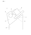
- a lathe in a machine tool 1 in the related art includes a bed 2 adjacently disposed on a ground, a main spindle 3 mounted on an upper surface of the bed 2, and a chuck mounted at a part of the main spindle 3 to grip a workpiece 8. Further, the lathe in the machine tool 1 includes a guide way 5 provided on an upper surface of the bed 2, a feed axis system 4 installed to be transferrable on the guide way 5, and a turret 6 installed on the feed axis system and fastened with a tool 7.
- the lathe In general, in the machine tool 1 in the related art, particularly, the lathe, the workpiece 8 and the tool 7 mounted on the turret 6 installed on the feed axis system 4 relatively move, so that the workpiece is processed in a desired shape.
- a general machine tool may have a structure, in which a part mounted with the tool is fixed, and the main spindle provided with the workpiece is transferred, and a structure, in which both the tool and the workpiece are transferred as necessary.
- the feed axis system 4 of the machine tool is driven by a power train unit, more particularly, a motor.
- the machine tool may also include an NC device as necessary.
- the machine tool 1 is used for processing a circular workpiece, and the feed axis system is operated at a high speed for reducing a processing time and massively producing a workpiece.
- a size of the workpiece or a size of a component configuring the feed axis system is deformed by heat generated when the feed axis system is operated at a high speed, so that there is a problem in that a diameter size of the workpiece is changed.
- a degree of processing precision of the workpiece is decreased according to the changed diameter size of the workpiece, and when the change of the diameter size of the workpiece exceeds a permissible tolerance, an operator needs to adjust the machine tool again, which degrades productivity.
- a device for compensating for a thermal displacement error by using a temperature sensor in the related art has been partially developed, but the device does not accurately compensate for a thermal displacement of the feed axis system, which is more rapidly operated than before for improving productivity, and manufacturing cost of equipment is increased due to high-priced components, such as a sensor.
- the present disclosure is to solve the above problem, and aims to provide a device and method for compensating thermal displacement of feed axis system of a machine tool, which is capable of obtaining rapid traverse time densities by calculating a time ratio used for rapid traverse per unit time, being used for exchanging tools or selecting a position of the tool as a processing point, and comparing a current compensation value with a maximum value, which is calculated based on an average value of the calculated rapid traverse time densities to compensate for the feed axis system according to thermal displacement of the feed axis system, thereby being applicable to various workpieces and machine tools, promptly compensating for thermal displacement of feed axis system according to a movement of the feed axis system, and reducing manufacturing cost.
- an exemplary embodiment of the present disclosure provides a device for compensating thermal displacement of feed axis system of a machine tool, which comprises a bed 2, a main spindle 3 mounted on the bed 2, a feed axis system 4 movably installed on the bed 2, and a power train unit configured to transmit power transferring the feed axis system 4, the device including: a timer 20 operated for a predetermined time when the feed axis system 4 is transferred; a rapid traverse time measuring unit 31 configured to measure a rapid traverse time of the feed axis system 4 while the timer 20 is operated; a rapid traverse time density calculating unit 32 configured to calculate a rapid traverse time density per unit time by using the rapid traverse time measured by the rapid traverse time measuring unit 31; an average rapid traverse time density calculating unit 34 configured to calculate an average rapid traverse time density based on the rapid traverse time density; a reference data storing unit 40 configured to store a thermal displacement increase rate, a thermal displacement decrease rate, and a
- the device for compensating for feed axis system thermal displacement for a machine tool may further include a rapid traverse time density storing unit 33 configured to store the rapid traverse time density calculated by the rapid traverse time density calculating unit 32.
- the control unit 50 may include: a compensation value calculating unit 51 configured to calculate a current compensation value; a maximum value calculating unit 52 configured to calculate a maximum value based on the average rapid traverse time density calculated by the average rapid traverse time density calculating unit 34 and the maximum value data stored in the reference data storing unit 40; a thermal displacement increase rate calculating unit 53 configured to calculate a thermal displacement increase rate based on the average rapid traverse time density calculated by the average rapid traverse time density calculating unit 34 and the thermal displacement increase rate data stored in the reference data storing unit 40; a thermal displacement decrease rate calculating unit 54 configured to calculate a thermal displacement decrease rate based on the average rapid traverse time density calculated by the average rapid traverse time density calculating unit 34 and the thermal displacement decrease rate data stored in the reference data storing unit 40; and a comparing unit 55 configured to compare the current compensation value calculated by the compensation value calculating unit 51 with the maximum value calculated
- Another exemplary embodiment of the present disclosure provides a method for compensating for thermal displacement of feed axis system of a machine tool, including: storing reference data of a thermal displacement increase rate, a thermal displacement decrease rate, and a maximum value (S1); operating a timer 20 for a predetermined time when a feed axis system 4 is transferred (S2); measuring a rapid traverse time of the feed axis system 4 while the timer 20 is operated (S3); calculating a rapid traverse time density per unit time based on the measured rapid traverse time (S4); calculating an average rapid traverse time density (S6); calculating a current compensation value (S7); calculating a maximum value based on the average rapid traverse time density and the maximum value data (S8); calculating a thermal displacement increase rate based on the average rapid traverse time density and the thermal displacement increase rate data (S9); calculating a thermal displacement decrease rate based on the average rapid traverse time density and the thermal displacement decrease rate data (S10); and comparing the current compensation value and the
- the method may further include: after the comparing of the current compensation value with the maximum value, compensating for the feed axis system 4 based on the thermal displacement decrease rate when the current compensation value is larger than the maximum value (S12-1); and compensating for the feed axis system 4 based on the thermal displacement increase rate when the current compensation value is smaller than the maximum value (S12-2).
- the device and method for compensating thermal displacement of feed axis system of a machine tool it is possible to compensate for thermal displacement based on a rapid traverse time, more particularly, an average rapid traverse time density of the feed axis system in real time, thereby improving a degree of processing precision of a workpiece.
- the device and method for compensating thermal displacement of feed axis system of a machine tool is applicable to various machine tools and workpieces, thereby improving productivity of the workpiece.
- the device and method for compensating thermal displacement of feed axis system of a machine tool does not require a high-priced configuration, such as a separate sensor, thereby reducing manufacturing cost of the machine tool.
- Machine tool 2 Bed 3: Main spindle 4: Feed axis system 5: Guide way 6: Turret 7: Tool 8: Workpiece 10: Thermal displacement compensating device 20: Timer 31: Rapid traverse time measuring unit 32: Rapid traverse time density calculating unit 33: Rapid traverse time density storing unit 34: Average rapid traverse time density calculating unit 40: Reference data storing unit 50: Control unit 51: Compensation value calculating unit 52: Maximum value calculating unit 53: Thermal displacement increase rate calculating unit 54: Thermal displacement decrease rate calculating unit 55: Comparing unit 100: Chuck 110: Workpiece 120: Tool 130: Turret 140, 150: Cutting transfer 160, 170: Rapid traverse
- FIG. 2 is a conceptual diagram for describing concepts of a cutting transfer and a rapid traverse according to the present disclosure.
- an operation of a feed axis system is divided into cutting transfers 140 and 150 actually cutting, by a tool 120 mounted on a turret 130, a workpiece 110 mounted on a chuck 100, and rapid traverses 160 and 170 exchanging the tool 120 or selecting a position of the tool 120.
- the cutting transfers 140 and 150 are performed at a low speed of several hundreds of mm per minute, so that a heat generation amount of the feed axis system is not large.
- a rapid traverse time means a time consumed for a rapid traverse.
- a rapid traverse density is 10%.
- a rapid traverse time density may be varied according to the kind of machine tool, a form, a kind, and a processing state of workpiece. Accordingly, according to the exemplary embodiment of the present disclosure, a rapid traverse time density is calculated a predetermined number of times in order to accurately calculate a rapid traverse time density, and heat displacement of the feed axis system is compensated based on an average of the rapid traverse time density, that is, an average rapid traverse time density.
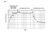
- FIG. 3 is a graph representing a size variation of a workpiece according to an elapse of time.
- an initial stage at which the machine tool is operated, represents a temperature increase section, in which a size of the workpiece is increased.
- frictional heat generated in the feed axis system is increased at an initial stage of the operation of the machine tool, a temperature of the feed axis system itself is increased according to the increase of the frictional heat, and a size of the workpiece is increased by the heat received through the feed axis system.
- the frictional heat generated in the feed axis system reaches a saturation state, and a temperature of the feed axis system is uniformly maintained from this time.
- a stable section in which the size of the workpiece is uniformly maintained, is represented.
- the heat generated in the feed axis system is discharged to the outside, so that the feed axis system is cooled, and thus a cooling section, in which the size of the workpiece is decreased, is represented.
- a thermal displacement increase rate means a thermal displacement increase rate when the machine tool starts to be operated in a state where the machine tool is completely cooled.
- the thermal displacement increase rate may be expressed with a change in a diameter size of the workpiece per unit time.
- a maximum value means a maximum thermal displacement value represented when a temperature increase is stopped and a temperature of the machine tool is stabilized.
- a thermal displacement decrease rate means a rate of a decrease of thermal displacement when an operation of the machine tool is stopped.
- Reference data for a thermal displacement increase rate, a maximum value, and a thermal displacement decrease rate by the temperature increase section, the stable section, and the cooling section may be determined through an experiment.
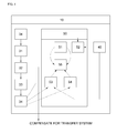
- FIG. 4 is a conceptual diagram of a thermal displacement compensating device 10 of a machine tool according to an exemplary embodiment of the present disclosure
- FIG. 5 is a table for calculating a thermal displacement increase rate, a maximum value, and a thermal displacement decrease rate according to average rapid traverse time intensities according to the exemplary embodiment of the present disclosure
- FIGS. 6A, 6B, and 6C are graphs representing a relationship between average rapid traverse time intensities and a thermal displacement increase rate, a maximum value, and a thermal displacement decrease rate according to the exemplary embodiment of the present disclosure.
- the thermal displacement compensating device 10 of a machine tool according to the present disclosure will be described with reference to FIGS. 4 to 6 .
- the thermal displacement compensating device 10 of a machine tool according to the present disclosure includes a timer 20, a rapid traverse time measuring unit 31, a rapid traverse time density calculating unit 32, an average rapid traverse time density calculating unit 34, a reference data storing unit 40, and a control unit 50.
- the thermal displacement compensating device 10 for a machine tool includes the aforementioned bed 2, main spindle 3, feed axis system 4, and power train unit.
- the timer 20 is operated for a predetermined time. Although not essentially limited thereto, according to the exemplary embodiment of the present disclosure, the timer is operated for 60 seconds after the feed axis system starts to be transferred.
- the rapid traverse time measuring unit 31 measures a rapid traverse time of the feed axis system 4 while the timer 20 is operated.
- the rapid traverse time means a transfer time of the feed axis system used for exchanging a tool or selecting a position of a tool as a processing point.
- the rapid traverse time density calculating unit 32 calculates a rapid traverse time density per unit time by using a rapid traverse time measured by the rapid traverse time measuring unit 31.
- a unit time of the rapid traverse time density calculating unit 32 may be set to 60 seconds, so that the rapid traverse time density may be calculated. That is, the rapid traverse time density calculating unit 32 calculates a rapid traverse time density through aforementioned Equation (1).
- a thermal displacement compensating device 10 of a machine may additionally include a rapid traverse time density storing unit 33 storing a rapid traverse time density calculated by the rapid traverse time density calculating unit 32.
- the average rapid traverse time density calculating unit 34 calculates an average rapid traverse time density based on the rapid traverse time density stored in the rapid traverse time density storing unit 33. Although not essentially limited thereto, the average rapid traverse time density calculating unit 34 according to the exemplary embodiment of the present disclosure calculates the rapid traverse time density stored in the rapid traverse time density storing unit 33 based on ten times. That is, the average rapid traverse time density calculating unit 34 calculates an average rapid traverse time density through aforementioned Equation (2).
- a temperature increase section, a stable section, and a cooling section illustrated in the graph of FIG. 2 are calculated for various machine tools and workpieces through an experiment, and reference data of a thermal displacement increase rate, a maximum value, and a thermal displacement decrease rate is stored in the reference data storing unit 40 based on the calculated sections.
- the control unit 50 includes a compensation value calculating unit 51, a maximum value calculating unit 52, a thermal displacement increase rate calculating unit 53, a thermal displacement decrease rate calculating unit 54, and a comparing unit 55.
- the compensation value calculating unit 51 calculates a current compensation value.
- a current compensation value is calculated by predetermined data according to the kind of machine tool and the form and the kind of workpiece.
- the maximum value calculating unit 52 calculates a maximum value based on the average rapid traverse time density calculated by the average rapid traverse time density calculating unit 34 and the maximum value data stored in the reference data storing unit 40.
- the thermal displacement increase rate calculating unit 53 calculates a thermal displacement increase rate based on the average rapid traverse time density calculated by the average rapid traverse time density calculating unit 34 and the thermal displacement increase rate data stored in the reference data storing unit 40.
- the thermal displacement decrease rate calculating unit 54 calculates a thermal displacement decrease rate based on the average rapid traverse time density calculated by the average rapid traverse time density calculating unit 34 and the thermal displacement decrease rate data stored in the reference data storing unit 40.
- a thermal displacement increase rate, a maximum value, and a thermal displacement decrease rate according to a corresponding average rapid traverse time density are calculated based on the average rapid traverse time density calculated by the average rapid traverse time density calculating unit 34 and the thermal displacement increase rate, the maximum value, and the thermal displacement decrease rate calculated by the experiment as illustrated in FIG. 3 and stored in the reference data storing unit 40.
- the thermal displacement increase rate, the maximum value, and the thermal displacement decrease rate for a value between sections of the average rapid traverse time density may be obtained by using a linear interpolation method.
- the comparing unit 55 compares the current compensation value calculated by the compensation value calculating unit 51 and the maximum value calculated by the maximum value calculating unit 52.
- the feed axis system is compensated based on the thermal displacement decrease rate calculated by the thermal displacement decrease rate calculating unit 54.
- the feed axis system is compensated based on the thermal displacement increase rate calculated by the thermal displacement increase rate calculating unit 53.
- FIG. 7 is a flowchart of a method for compensating thermal displacement of feed axis system of a machine tool according to another exemplary embodiment of the present disclosure.
- the method for compensating thermal displacement of feed axis system of a machine tool according to the present disclosure includes storing reference data (S1), operating the timer (S2), measuring a rapid traverse time (S3), calculating a rapid traverse time density (S4), calculating an average rapid traverse time density (S6), calculating a current compensation value (S7), calculating a maximum value (S8), calculating a thermal displacement increase rate (S9), calculating a thermal displacement decrease rate (S10), and comparing the current compensation value with the maximum value (S11).
- reference data of the thermal displacement increase rate, the thermal displacement decrease rate, and the maximum value based on experimental values according to the various kinds of a machine tool and the kind of workpiece are stored in the reference data storing unit 40.
- the timer 20 is operated for a predetermined time. According to the exemplary embodiment of the method for compensating thermal displacement of feed axis system of a machine tool according to the present disclosure, the timer is operated for 60 seconds.
- the rapid traverse time measuring unit 31 measures a rapid traverse time of the feed axis system 4 for an operation time of the timer 20.
- the rapid traverse time calculating unit 32 calculates a rapid traverse time density that is a rapid traverse time per unit time based on the measured rapid traverse time.
- the rapid traverse time density in the calculating the rapid traverse time density(S4) is calculated by aforementioned Equation (1).
- the average rapid traverse time density calculating unit 34 calculates an average rapid traverse time density based on the rapid traverse time density.
- the average rapid traverse time density is calculated by the aforementioned Equation (2).
- the compensation value calculating unit 51 calculates a current compensation value based on the stored data.
- a maximum value is calculated based on the average rapid traverse time density calculated by the average rapid traverse time density calculating unit 33 and the maximum value data stored in the reference data storing unit 40.
- a thermal displacement increase rate is calculated based on the average rapid traverse time density calculated by the average rapid traverse time density calculating unit 33 and the thermal displacement increase rate data stored in the reference data storing unit 40.
- a thermal displacement decrease rate is calculated based on the average rapid traverse time density calculated by the average rapid traverse time density calculating unit 33 and the thermal displacement decrease rate data stored in the reference data storing unit 40.
- the current compensation value calculated by the compensation value calculating unit 51 is compared with the maximum value calculated by the maximum value calculating unit 52.
- the current compensation value is compared with the maximum value, and when the current compensation value is larger than the maximum value, the feed axis system 4 is compensated based on the thermal displacement decrease rate (S12-1).
- the feed axis system 4 is compensated based on the thermal displacement increase rate (S12-2).
- the device and method for compensating thermal displacement of feed axis system of a machine tool compensates for the feed axis system considering a heat generation amount according to the transfer of the feed axis system by using an average rapid traverse time density based on a rapid traverse time density of the feed axis system, thereby improving a degree of processing precision of a workpiece and generally reducing manufacturing cost of a machine tool.
- the present disclosure relates to a device and method for compensating thermal displacement of feed axis system of a machine tool, which obtains rapid traverse time density by calculating a time ratio used for rapid traverse per unit time, being used for exchanging tools or selecting a position of the tool as a processing point, and compares a current compensation value with a maximum value, which is calculated based on an average value of the calculated rapid traverse time density to compensate for the feed axis system according to thermal displacement of the feed axis system.
Landscapes
- Engineering & Computer Science (AREA)
- Physics & Mathematics (AREA)
- General Physics & Mathematics (AREA)
- Mechanical Engineering (AREA)
- Human Computer Interaction (AREA)
- Manufacturing & Machinery (AREA)
- Automation & Control Theory (AREA)
- Automatic Control Of Machine Tools (AREA)
- Numerical Control (AREA)
Abstract
Description
- The present disclosure relates to a device and method for compensating thermal displacement of feed axis system of a machine tool, and more particularly, to a device and method for compensating thermal displacement of feed axis system of a machine tool, which is capable of obtaining rapid traverse time density by calculating a time ratio used for rapid traverse per unit time, being used for exchanging tools or selecting a position of the tool as a processing point, and comparing a current compensation value with a maximum value, which is calculated based on an average value of the calculated rapid traverse time density to compensate for the feed axis system according to thermal displacement of the feed axis system.
- Various kinds of machine tool, such as a turning center, a machining center, and a boring machine have been widely used in various industrial sites in accordance with a use of a corresponding operation.
- As illustrated in
FIG. 1 , a lathe in amachine tool 1 in the related art includes abed 2 adjacently disposed on a ground, amain spindle 3 mounted on an upper surface of thebed 2, and a chuck mounted at a part of themain spindle 3 to grip aworkpiece 8. Further, the lathe in themachine tool 1 includes aguide way 5 provided on an upper surface of thebed 2, afeed axis system 4 installed to be transferrable on theguide way 5, and aturret 6 installed on the feed axis system and fastened with atool 7. - In general, in the
machine tool 1 in the related art, particularly, the lathe, theworkpiece 8 and thetool 7 mounted on theturret 6 installed on thefeed axis system 4 relatively move, so that the workpiece is processed in a desired shape. - A general machine tool may have a structure, in which a part mounted with the tool is fixed, and the main spindle provided with the workpiece is transferred, and a structure, in which both the tool and the workpiece are transferred as necessary.
- The
feed axis system 4 of the machine tool is driven by a power train unit, more particularly, a motor. In order to more accurately control the feed axis system, the machine tool may also include an NC device as necessary. - In general, the
machine tool 1, particularly, the lathe, is used for processing a circular workpiece, and the feed axis system is operated at a high speed for reducing a processing time and massively producing a workpiece. A size of the workpiece or a size of a component configuring the feed axis system is deformed by heat generated when the feed axis system is operated at a high speed, so that there is a problem in that a diameter size of the workpiece is changed. - Further, a degree of processing precision of the workpiece is decreased according to the changed diameter size of the workpiece, and when the change of the diameter size of the workpiece exceeds a permissible tolerance, an operator needs to adjust the machine tool again, which degrades productivity.
- Further, in order to improve a degree of processing precision and productivity of the workpiece by thermal deformation of the feed axis system, a device for compensating for a thermal displacement error by using a temperature sensor in the related art has been partially developed, but the device does not accurately compensate for a thermal displacement of the feed axis system, which is more rapidly operated than before for improving productivity, and manufacturing cost of equipment is increased due to high-priced components, such as a sensor.
- The present disclosure is to solve the above problem, and aims to provide a device and method for compensating thermal displacement of feed axis system of a machine tool, which is capable of obtaining rapid traverse time densities by calculating a time ratio used for rapid traverse per unit time, being used for exchanging tools or selecting a position of the tool as a processing point, and comparing a current compensation value with a maximum value, which is calculated based on an average value of the calculated rapid traverse time densities to compensate for the feed axis system according to thermal displacement of the feed axis system, thereby being applicable to various workpieces and machine tools, promptly compensating for thermal displacement of feed axis system according to a movement of the feed axis system, and reducing manufacturing cost.
- In order to achieve the object of the present disclosure, an exemplary embodiment of the present disclosure provides a device for compensating thermal displacement of feed axis system of a machine tool, which comprises a
bed 2, amain spindle 3 mounted on thebed 2, afeed axis system 4 movably installed on thebed 2, and a power train unit configured to transmit power transferring thefeed axis system 4, the device including: atimer 20 operated for a predetermined time when thefeed axis system 4 is transferred; a rapid traversetime measuring unit 31 configured to measure a rapid traverse time of thefeed axis system 4 while thetimer 20 is operated; a rapid traverse timedensity calculating unit 32 configured to calculate a rapid traverse time density per unit time by using the rapid traverse time measured by the rapid traversetime measuring unit 31; an average rapid traverse timedensity calculating unit 34 configured to calculate an average rapid traverse time density based on the rapid traverse time density; a referencedata storing unit 40 configured to store a thermal displacement increase rate, a thermal displacement decrease rate, and a maximum value; and acontrol unit 50. - Further, in the exemplary embodiment of the device for compensating thermal displacement of feed axis system of a machine tool according to the present disclosure, the device for compensating for feed axis system thermal displacement for a machine tool may further include a rapid traverse time
density storing unit 33 configured to store the rapid traverse time density calculated by the rapid traverse timedensity calculating unit 32. - Further, in the exemplary embodiment of the device for compensating thermal displacement of feed axis system of a machine tool according to the present disclosure, the
control unit 50 may include: a compensationvalue calculating unit 51 configured to calculate a current compensation value; a maximumvalue calculating unit 52 configured to calculate a maximum value based on the average rapid traverse time density calculated by the average rapid traverse timedensity calculating unit 34 and the maximum value data stored in the referencedata storing unit 40; a thermal displacement increaserate calculating unit 53 configured to calculate a thermal displacement increase rate based on the average rapid traverse time density calculated by the average rapid traverse timedensity calculating unit 34 and the thermal displacement increase rate data stored in the referencedata storing unit 40; a thermal displacement decreaserate calculating unit 54 configured to calculate a thermal displacement decrease rate based on the average rapid traverse time density calculated by the average rapid traverse timedensity calculating unit 34 and the thermal displacement decrease rate data stored in the referencedata storing unit 40; and a comparingunit 55 configured to compare the current compensation value calculated by the compensationvalue calculating unit 51 with the maximum value calculated by the maximum value calculating unit, and when the current compensation value is larger than the maximum value, thefeed axis system 4 may be compensated based on the thermal displacement decrease rate, and when the current compensation value may be smaller than the maximum value, thefeed axis system 4 is compensated based on the thermal displacement increase rate. - Another exemplary embodiment of the present disclosure provides a method for compensating for thermal displacement of feed axis system of a machine tool, including: storing reference data of a thermal displacement increase rate, a thermal displacement decrease rate, and a maximum value (S1); operating a
timer 20 for a predetermined time when afeed axis system 4 is transferred (S2); measuring a rapid traverse time of thefeed axis system 4 while thetimer 20 is operated (S3); calculating a rapid traverse time density per unit time based on the measured rapid traverse time (S4); calculating an average rapid traverse time density (S6); calculating a current compensation value (S7); calculating a maximum value based on the average rapid traverse time density and the maximum value data (S8); calculating a thermal displacement increase rate based on the average rapid traverse time density and the thermal displacement increase rate data (S9); calculating a thermal displacement decrease rate based on the average rapid traverse time density and the thermal displacement decrease rate data (S10); and comparing the current compensation value and the maximum value (S11). - Further, in the exemplary embodiment of the method for compensating thermal displacement of feed axis system of a machine tool according to the present disclosure, the method may further include: after the comparing of the current compensation value with the maximum value, compensating for the
feed axis system 4 based on the thermal displacement decrease rate when the current compensation value is larger than the maximum value (S12-1); and compensating for thefeed axis system 4 based on the thermal displacement increase rate when the current compensation value is smaller than the maximum value (S12-2). - According to the device and method for compensating thermal displacement of feed axis system of a machine tool, it is possible to compensate for thermal displacement based on a rapid traverse time, more particularly, an average rapid traverse time density of the feed axis system in real time, thereby improving a degree of processing precision of a workpiece.
- Further, the device and method for compensating thermal displacement of feed axis system of a machine tool is applicable to various machine tools and workpieces, thereby improving productivity of the workpiece.
- Furthermore, the device and method for compensating thermal displacement of feed axis system of a machine tool does not require a high-priced configuration, such as a separate sensor, thereby reducing manufacturing cost of the machine tool.
-
-
FIG. 1 is a schematic diagram of a machine tool in the related art. -
FIG. 2 is a conceptual diagram for describing concepts of a cutting transfer and a rapid traverse according to the present disclosure. -
FIG. 3 is a graph representing a size variation of a workpiece according to an elapse of time. -
FIG. 4 is a conceptual diagram of a thermal displacement compensating device of a machine tool according to an exemplary embodiment of the present disclosure. -
FIG. 5 is a table for calculating a thermal displacement increase rate, a maximum value, and a thermal displacement decrease rate according to average rapid traverse time intensities according to the exemplary embodiment of the present disclosure. -
FIGS. 6A, 6B, and 6C are graphs representing a relationship between average rapid traverse time intensities and a thermal displacement increase rate, a maximum value, and a thermal displacement decrease rate according to the exemplary embodiment of the present disclosure. -
FIG. 7 is a flowchart of a method for compensating thermal displacement of a feed axis system of a machine tool according to an exemplary embodiment of the present disclosure. -
1: Machine tool 2: Bed 3: Main spindle 4: Feed axis system 5: Guide way 6: Turret 7: Tool 8: Workpiece 10: Thermal displacement compensating device 20: Timer 31: Rapid traverse time measuring unit 32: Rapid traverse time density calculating unit 33: Rapid traverse time density storing unit 34: Average rapid traverse time density calculating unit 40: Reference data storing unit 50: Control unit 51: Compensation value calculating unit 52: Maximum value calculating unit 53: Thermal displacement increase rate calculating unit 54: Thermal displacement decrease rate calculating unit 55: Comparing unit 100: Chuck 110: Workpiece 120: Tool 130: Turret 140, 150: Cutting transfer 160, 170: Rapid traverse - Hereinafter, an exemplary embodiment of the present disclosure will be described in detail with reference to the accompanying drawings. First of all, in giving reference numerals to elements of each drawing, like reference numerals refer to like elements.
-
FIG. 2 is a conceptual diagram for describing concepts of a cutting transfer and a rapid traverse according to the present disclosure. As illustrated inFIG. 2 , an operation of a feed axis system, particularly, a lathe feed axis system, is divided intocutting transfers tool 120 mounted on aturret 130, aworkpiece 110 mounted on achuck 100, andrapid traverses tool 120 or selecting a position of thetool 120. In general, thecutting transfers rapid traverses workpiece 110 according to thermal displacement of the feed axis system is therapid traverses - In a device and method for compensating thermal displacement of feed axis system of a machine tool according to an exemplary embodiment of the present disclosure, a rapid traverse time means a time consumed for a rapid traverse. Further, a rapid traverse time density means a time ratio (Equation (1) below) used for the rapid traverse per unit time

- For example, when a rapid traverse time for 60 seconds is six seconds, a rapid traverse density is 10%.
- A rapid traverse time density may be varied according to the kind of machine tool, a form, a kind, and a processing state of workpiece. Accordingly, according to the exemplary embodiment of the present disclosure, a rapid traverse time density is calculated a predetermined number of times in order to accurately calculate a rapid traverse time density, and heat displacement of the feed axis system is compensated based on an average of the rapid traverse time density, that is, an average rapid traverse time density. The average rapid traverse time density is generally calculated by dividing a value obtained by measuring a rapid
traverse time density 10 times by 10 (Equation (2)).
-
FIG. 3 is a graph representing a size variation of a workpiece according to an elapse of time. As illustrated inFIG. 3 , an initial stage, at which the machine tool is operated, represents a temperature increase section, in which a size of the workpiece is increased. In this case, frictional heat generated in the feed axis system is increased at an initial stage of the operation of the machine tool, a temperature of the feed axis system itself is increased according to the increase of the frictional heat, and a size of the workpiece is increased by the heat received through the feed axis system. At a middle stage of the operation of the machine tool, the frictional heat generated in the feed axis system reaches a saturation state, and a temperature of the feed axis system is uniformly maintained from this time. Accordingly, a stable section, in which the size of the workpiece is uniformly maintained, is represented. When the operation of the machine tool is stopped, the heat generated in the feed axis system is discharged to the outside, so that the feed axis system is cooled, and thus a cooling section, in which the size of the workpiece is decreased, is represented. - In the exemplary embodiment of the device and method for compensating thermal displacement of feed axis system of a machine tool according to the present disclosure, a thermal displacement increase rate means a thermal displacement increase rate when the machine tool starts to be operated in a state where the machine tool is completely cooled. The thermal displacement increase rate may be expressed with a change in a diameter size of the workpiece per unit time. A maximum value means a maximum thermal displacement value represented when a temperature increase is stopped and a temperature of the machine tool is stabilized. A thermal displacement decrease rate means a rate of a decrease of thermal displacement when an operation of the machine tool is stopped.
- Reference data for a thermal displacement increase rate, a maximum value, and a thermal displacement decrease rate by the temperature increase section, the stable section, and the cooling section may be determined through an experiment.
-
FIG. 4 is a conceptual diagram of a thermaldisplacement compensating device 10 of a machine tool according to an exemplary embodiment of the present disclosure, andFIG. 5 is a table for calculating a thermal displacement increase rate, a maximum value, and a thermal displacement decrease rate according to average rapid traverse time intensities according to the exemplary embodiment of the present disclosure.FIGS. 6A, 6B, and 6C are graphs representing a relationship between average rapid traverse time intensities and a thermal displacement increase rate, a maximum value, and a thermal displacement decrease rate according to the exemplary embodiment of the present disclosure. - The thermal
displacement compensating device 10 of a machine tool according to the present disclosure will be described with reference toFIGS. 4 to 6 . The thermaldisplacement compensating device 10 of a machine tool according to the present disclosure includes atimer 20, a rapid traversetime measuring unit 31, a rapid traverse timedensity calculating unit 32, an average rapid traverse timedensity calculating unit 34, a referencedata storing unit 40, and acontrol unit 50. - Although not essentially limited thereto, the thermal
displacement compensating device 10 for a machine tool according to the exemplary embodiment of the present disclosure includes theaforementioned bed 2,main spindle 3, feedaxis system 4, and power train unit. - When the
feed axis system 4 is transferred, thetimer 20 is operated for a predetermined time. Although not essentially limited thereto, according to the exemplary embodiment of the present disclosure, the timer is operated for 60 seconds after the feed axis system starts to be transferred. - The rapid traverse
time measuring unit 31 measures a rapid traverse time of thefeed axis system 4 while thetimer 20 is operated. As described above, the rapid traverse time means a transfer time of the feed axis system used for exchanging a tool or selecting a position of a tool as a processing point. - The rapid traverse time
density calculating unit 32 calculates a rapid traverse time density per unit time by using a rapid traverse time measured by the rapid traversetime measuring unit 31. Although not essentially limited thereto, according to the exemplary embodiment of the present disclosure, a unit time of the rapid traverse timedensity calculating unit 32 may be set to 60 seconds, so that the rapid traverse time density may be calculated. That is, the rapid traverse timedensity calculating unit 32 calculates a rapid traverse time density through aforementioned Equation (1). - According to another exemplary embodiment of the present disclosure, a thermal
displacement compensating device 10 of a machine may additionally include a rapid traverse timedensity storing unit 33 storing a rapid traverse time density calculated by the rapid traverse timedensity calculating unit 32. - The average rapid traverse time
density calculating unit 34 calculates an average rapid traverse time density based on the rapid traverse time density stored in the rapid traverse timedensity storing unit 33. Although not essentially limited thereto, the average rapid traverse timedensity calculating unit 34 according to the exemplary embodiment of the present disclosure calculates the rapid traverse time density stored in the rapid traverse timedensity storing unit 33 based on ten times. That is, the average rapid traverse timedensity calculating unit 34 calculates an average rapid traverse time density through aforementioned Equation (2). - A temperature increase section, a stable section, and a cooling section illustrated in the graph of
FIG. 2 are calculated for various machine tools and workpieces through an experiment, and reference data of a thermal displacement increase rate, a maximum value, and a thermal displacement decrease rate is stored in the referencedata storing unit 40 based on the calculated sections. - As illustrated in
FIG. 4 , according to another exemplary embodiment of the present disclosure, thecontrol unit 50 includes a compensationvalue calculating unit 51, a maximumvalue calculating unit 52, a thermal displacement increaserate calculating unit 53, a thermal displacement decreaserate calculating unit 54, and a comparingunit 55. - The compensation
value calculating unit 51 calculates a current compensation value. According to the exemplary embodiment of the present disclosure, a current compensation value is calculated by predetermined data according to the kind of machine tool and the form and the kind of workpiece. - The maximum
value calculating unit 52 calculates a maximum value based on the average rapid traverse time density calculated by the average rapid traverse timedensity calculating unit 34 and the maximum value data stored in the referencedata storing unit 40. - The thermal displacement increase
rate calculating unit 53 calculates a thermal displacement increase rate based on the average rapid traverse time density calculated by the average rapid traverse timedensity calculating unit 34 and the thermal displacement increase rate data stored in the referencedata storing unit 40. - The thermal displacement decrease
rate calculating unit 54 calculates a thermal displacement decrease rate based on the average rapid traverse time density calculated by the average rapid traverse timedensity calculating unit 34 and the thermal displacement decrease rate data stored in the referencedata storing unit 40. - As represented in the table of
FIG. 5 , a thermal displacement increase rate, a maximum value, and a thermal displacement decrease rate according to a corresponding average rapid traverse time density are calculated based on the average rapid traverse time density calculated by the average rapid traverse timedensity calculating unit 34 and the thermal displacement increase rate, the maximum value, and the thermal displacement decrease rate calculated by the experiment as illustrated inFIG. 3 and stored in the referencedata storing unit 40. - The thermal displacement increase rate, the maximum value, and the thermal displacement decrease rate for a value between sections of the average rapid traverse time density may be obtained by using a linear interpolation method.
- The comparing
unit 55 compares the current compensation value calculated by the compensationvalue calculating unit 51 and the maximum value calculated by the maximumvalue calculating unit 52. - When the current compensation value is larger than the maximum value as a result of the comparison by the comparing
unit 55, the feed axis system is compensated based on the thermal displacement decrease rate calculated by the thermal displacement decreaserate calculating unit 54. - When the current compensation value is smaller than the maximum value as a result of the comparison by the comparing
unit 55, the feed axis system is compensated based on the thermal displacement increase rate calculated by the thermal displacement increaserate calculating unit 53. -
FIG. 7 is a flowchart of a method for compensating thermal displacement of feed axis system of a machine tool according to another exemplary embodiment of the present disclosure. - The method for compensating thermal displacement of feed axis system of a machine tool according to the present disclosure will be described with reference to
FIG. 7 . The method for compensating thermal displacement of feed axis system of machine tool according to the present disclosure includes storing reference data (S1), operating the timer (S2), measuring a rapid traverse time (S3), calculating a rapid traverse time density (S4), calculating an average rapid traverse time density (S6), calculating a current compensation value (S7), calculating a maximum value (S8), calculating a thermal displacement increase rate (S9), calculating a thermal displacement decrease rate (S10), and comparing the current compensation value with the maximum value (S11). - As illustrated in
FIG. 3 , reference data of the thermal displacement increase rate, the thermal displacement decrease rate, and the maximum value based on experimental values according to the various kinds of a machine tool and the kind of workpiece are stored in the referencedata storing unit 40. - After the storing reference data (S1), when the
feed axis system 4 is transferred, thetimer 20 is operated for a predetermined time. According to the exemplary embodiment of the method for compensating thermal displacement of feed axis system of a machine tool according to the present disclosure, the timer is operated for 60 seconds. - After the operating the timer (S2), the rapid traverse
time measuring unit 31 measures a rapid traverse time of thefeed axis system 4 for an operation time of thetimer 20. - After the measuring the rapid traverse time (S3), the rapid traverse
time calculating unit 32 calculates a rapid traverse time density that is a rapid traverse time per unit time based on the measured rapid traverse time. According to the exemplary embodiment of the method for compensating thermal displacement of feed axis system of a machine tool according to the present disclosure, the rapid traverse time density in the calculating the rapid traverse time density(S4) is calculated by aforementioned Equation (1). - After the calculating the rapid traverse time density (S4), the average rapid traverse time
density calculating unit 34 calculates an average rapid traverse time density based on the rapid traverse time density. According to the exemplary embodiment of the method for compensating thermal displacement of a feed axis system of a machine tool according to the present disclosure, the average rapid traverse time density is calculated by the aforementioned Equation (2). - After the calculatingthe average rapid traverse time density (S6), the compensation
value calculating unit 51 calculates a current compensation value based on the stored data. - After the calculating the current compensation value (S7), a maximum value is calculated based on the average rapid traverse time density calculated by the average rapid traverse time
density calculating unit 33 and the maximum value data stored in the referencedata storing unit 40. - After the calculating the maximum value (S8), a thermal displacement increase rate is calculated based on the average rapid traverse time density calculated by the average rapid traverse time
density calculating unit 33 and the thermal displacement increase rate data stored in the referencedata storing unit 40. - After the calculating the thermal displacement increase rate (S9), a thermal displacement decrease rate is calculated based on the average rapid traverse time density calculated by the average rapid traverse time
density calculating unit 33 and the thermal displacement decrease rate data stored in the referencedata storing unit 40. - After the calculating the thermal displacement decrease rate (S10), the current compensation value calculated by the compensation
value calculating unit 51 is compared with the maximum value calculated by the maximumvalue calculating unit 52. - As illustrated in
FIG. 7 , according to the exemplary embodiment of the method for compensating thermal displacement of a feed axis system of a machine tool according to the present disclosure, the current compensation value is compared with the maximum value, and when the current compensation value is larger than the maximum value, thefeed axis system 4 is compensated based on the thermal displacement decrease rate (S12-1). - When the current compensation value is smaller than the maximum value, the
feed axis system 4 is compensated based on the thermal displacement increase rate (S12-2). - As described above, the device and method for compensating thermal displacement of feed axis system of a machine tool according to the present disclosure compensates for the feed axis system considering a heat generation amount according to the transfer of the feed axis system by using an average rapid traverse time density based on a rapid traverse time density of the feed axis system, thereby improving a degree of processing precision of a workpiece and generally reducing manufacturing cost of a machine tool.
- The aforementioned contents are mainly described based on the lathe machine tool, but the present disclosure is not essentially limited thereto, and is applicable to another machine tool.
- Further, the present disclosure is not limited to a modification example illustrated in the drawing and the aforementioned exemplary embodiments, and may be expanded to another exemplary embodiment belonging to the scope of the accompanying claims.
- The present disclosure relates to a device and method for compensating thermal displacement of feed axis system of a machine tool, which obtains rapid traverse time density by calculating a time ratio used for rapid traverse per unit time, being used for exchanging tools or selecting a position of the tool as a processing point, and compares a current compensation value with a maximum value, which is calculated based on an average value of the calculated rapid traverse time density to compensate for the feed axis system according to thermal displacement of the feed axis system.
Claims (5)
- A device for compensating thermal displacement of feed axis system of a machine tool, which comprises a bed (2), a main spindle (3) mounted on the bed (2), a feed axis system (4) movably installed on the bed (2), and a power train unit configured to transmit power transferring the feed axis system (4), the device comprising: a timer (20) operated for a predetermined time when the feed axis system (4) is transferred;
a rapid traverse time measuring unit (31) configured to measure a rapid traverse time of the feed axis system (4) while the timer (20) is operated;
a rapid traverse time density calculating unit (32) configured to calculate a rapid traverse time density per unit time by using the rapid traverse time measured by the rapid traverse time measuring unit (31);
an average rapid traverse time density calculating unit (34) configured to calculate an average rapid traverse time density based on the rapid traverse time density;
a reference data storing unit (40) configured to store a thermal displacement increase rate, a thermal displacement decrease rate, and a maximum value; and
a control unit (50). - The device of claim 1, further comprising:a rapid traverse time density storing unit (33) configured to store the rapid traverse time density calculated by the rapid traverse time density calculating unit (32).
- The device of claim 1 or 2, wherein the control unit (50) includes:a compensation value calculating unit (51) configured to calculate a current compensation value;a maximum value calculating unit (52) configured to calculate a maximum value based on the average rapid traverse time density calculated by the average rapid traverse time density calculating unit (34) and the maximum value data stored in the reference data storing unit (40);a thermal displacement increase rate calculating unit (53) configured to calculate a thermal displacement increase rate based on the average rapid traverse time density calculated by the average rapid traverse time density calculating unit (34) and the thermal displacement increase rate data stored in the reference data storing unit (40);a thermal displacement decrease rate calculating unit (54) configured to calculate a thermal displacement decrease rate based on the average rapid traverse time density calculated by the average rapid traverse time density calculating unit (34) and the thermal displacement decrease rate data stored in the reference data storing unit (40); anda comparing unit (55) configured to compare the current compensation value calculated by the compensation value calculating unit (51) with the maximum value calculated by the maximum value calculating unit(52), andwhen the current compensation value is larger than the maximum value, the feed axis system (4) is compensated based on the thermal displacement decrease rate, andwhen the current compensation value is smaller than the maximum value, the feed axis system (4) is compensated based on the thermal displacement increase rate.
- A method for compensating thermal displacement of feed axis system of a machine tool, comprising: storing reference data of a thermal displacement increase rate, a thermal displacement decrease rate, and a maximum value (S1);
operating a timer for a predetermined time when a feed axis system (4) is transferred (S2);
measuring a rapid traverse time of the feed axis system (4) while the timer (20) is operated (S3);
calculating a rapid traverse time density per unit time based on the measured rapid traverse time (S4);
calculating an average rapid traverse time density (S6);
calculating a current compensation value (S7);
calculating a maximum value based on the average rapid traverse time density and the maximum value data (S8);
calculating a thermal displacement increase rate based on the average rapid traverse time density and the thermal displacement increase rate data (S9);
calculating a thermal displacement decrease rate based on the average rapid traverse time density and the thermal displacement decrease rate data (S10); and
comparing the current compensation value with the maximum value (S11). - The method of claim 4, further comprising:after the comparing the current compensation value with the maximum value(S11),compensating for the feed axis system (4) based on the thermal displacement decrease rate when the current compensation value is larger than the maximum value (S12-1); andcompensating for the feed axis system (4) based on the thermal displacement increase rate when the current compensation value is smaller than the maximum value (12-2).
Applications Claiming Priority (2)
| Application Number | Priority Date | Filing Date | Title |
|---|---|---|---|
| KR1020130005821A KR102109982B1 (en) | 2013-01-18 | 2013-01-18 | Feed drive system thermal deformation correction device of machine tool and method thereof |
| PCT/KR2014/000307 WO2014112752A1 (en) | 2013-01-18 | 2014-01-10 | Transfer system thermal displacement compensating device and compensating method for machine tools |
Publications (3)
| Publication Number | Publication Date |
|---|---|
| EP2946877A1 true EP2946877A1 (en) | 2015-11-25 |
| EP2946877A4 EP2946877A4 (en) | 2016-10-26 |
| EP2946877B1 EP2946877B1 (en) | 2019-12-25 |
Family
ID=51209810
Family Applications (1)
| Application Number | Title | Priority Date | Filing Date |
|---|---|---|---|
| EP14741169.8A Active EP2946877B1 (en) | 2013-01-18 | 2014-01-10 | Transfer system thermal displacement compensating device and compensating method for machine tools |
Country Status (3)
| Country | Link |
|---|---|
| EP (1) | EP2946877B1 (en) |
| KR (1) | KR102109982B1 (en) |
| WO (1) | WO2014112752A1 (en) |
Families Citing this family (2)
| Publication number | Priority date | Publication date | Assignee | Title |
|---|---|---|---|---|
| KR102067843B1 (en) * | 2013-12-10 | 2020-02-11 | 두산공작기계 주식회사 | Feed drive system thermal deformation correction device of machine tool and method thereof |
| CN109070295B (en) * | 2016-03-28 | 2020-10-27 | 斗山机床株式会社 | Automatic conversion device and conversion method for thermal displacement compensation parameters of machine tool |
Family Cites Families (10)
| Publication number | Priority date | Publication date | Assignee | Title |
|---|---|---|---|---|
| JPS62199343A (en) * | 1986-02-25 | 1987-09-03 | Fanuc Ltd | Machining time indication method for simultaneous four-axis lathe |
| JPH02294803A (en) * | 1989-05-10 | 1990-12-05 | Mori Seiki Seisakusho:Kk | Device with thermal displacement correcting function |
| JP3702496B2 (en) * | 1995-07-10 | 2005-10-05 | 三菱電機株式会社 | Machining method using numerical controller |
| JP3136464B2 (en) * | 1995-09-22 | 2001-02-19 | オークマ株式会社 | Thermal displacement compensation method for machine tools |
| KR20010050212A (en) | 1999-09-13 | 2001-06-15 | 스테븐 디.피터스 | Access control system for files on a memory card |
| JP4299761B2 (en) * | 2004-10-22 | 2009-07-22 | ヤマザキマザック株式会社 | Thermal displacement correction method and thermal displacement correction apparatus for machine tool |
| KR20120044638A (en) * | 2010-10-28 | 2012-05-08 | 주식회사아일 | Correction apparatus and method for deformation in hobbing machine |
| JP4917665B1 (en) * | 2010-11-11 | 2012-04-18 | ファナック株式会社 | Thermal displacement correction method and thermal displacement correction apparatus for machine tool |
| KR20120069056A (en) * | 2010-12-20 | 2012-06-28 | 두산인프라코어 주식회사 | The main axis heat displacement correction unit using tools measuring of cnc and method thereof |
| KR20140092078A (en) * | 2013-01-15 | 2014-07-23 | 김성철 | Thermal deformation correction method for ball screw of machining centers |
-
2013
- 2013-01-18 KR KR1020130005821A patent/KR102109982B1/en active Active
-
2014
- 2014-01-10 WO PCT/KR2014/000307 patent/WO2014112752A1/en not_active Ceased
- 2014-01-10 EP EP14741169.8A patent/EP2946877B1/en active Active
Also Published As
| Publication number | Publication date |
|---|---|
| WO2014112752A1 (en) | 2014-07-24 |
| EP2946877B1 (en) | 2019-12-25 |
| EP2946877A4 (en) | 2016-10-26 |
| KR20140093847A (en) | 2014-07-29 |
| KR102109982B1 (en) | 2020-05-13 |
Similar Documents
| Publication | Publication Date | Title |
|---|---|---|
| US6291959B1 (en) | Method and apparatus for controlling numerically controlled machine tool | |
| US9448552B2 (en) | Numerically-controlled machine tool and spindle error compensating method thereof | |
| US8240060B2 (en) | Methods and apparatus for compensating temperature-dependent changes of positions on machine tools | |
| EP1300738B1 (en) | Offset apparatus for NC machine tool | |
| US9317084B2 (en) | Thermal displacement compensating device and method for a machine tool | |
| US10274927B2 (en) | Method of machining workpiece using machine tool, and machine tool | |
| JP2942547B2 (en) | Method and apparatus for correcting thermal displacement of machine tool | |
| JP2007042068A (en) | Servo controller | |
| CN107580535A (en) | Method for operating a gear machining machine tool | |
| US20150277424A1 (en) | Method and apparatus for controlling a machine tool | |
| EP2946877B1 (en) | Transfer system thermal displacement compensating device and compensating method for machine tools | |
| US20140364993A1 (en) | Control method for machine tool | |
| CN106695451A (en) | Machining device and control device and method for machined workpieces thereof | |
| JP5531640B2 (en) | Feed control device for machine tools | |
| JP2019188505A (en) | Machine tool | |
| JP2009142915A (en) | Machine tool and machining method using the same | |
| JP5855840B2 (en) | 2-spindle facing NC lathe and vibration isolation method | |
| JP5397095B2 (en) | Thermal displacement compensation method and thermal displacement compensation device for numerically controlled machine tool | |
| RU2544713C1 (en) | Method of mechanical treatment of stocks on nc machines | |
| KR102067843B1 (en) | Feed drive system thermal deformation correction device of machine tool and method thereof | |
| KR19980032160A (en) | Electric discharge processing device and electric discharge processing method | |
| EP3540538B1 (en) | Compensation quantity acquisition device, feed mechanism control device, compensation quantity acquiring method and feed mechanism control method | |
| JP2022097299A (en) | Design device | |
| JP7091984B2 (en) | Correction system, machine tool and correction method | |
| Ma et al. | Robot machining accuracy control based on terminal closed-loop compensation |
Legal Events
| Date | Code | Title | Description |
|---|---|---|---|
| PUAI | Public reference made under article 153(3) epc to a published international application that has entered the european phase |
Free format text: ORIGINAL CODE: 0009012 |
|
| 17P | Request for examination filed |
Effective date: 20150813 |
|
| AK | Designated contracting states |
Kind code of ref document: A1 Designated state(s): AL AT BE BG CH CY CZ DE DK EE ES FI FR GB GR HR HU IE IS IT LI LT LU LV MC MK MT NL NO PL PT RO RS SE SI SK SM TR |
|
| AX | Request for extension of the european patent |
Extension state: BA ME |
|
| DAX | Request for extension of the european patent (deleted) | ||
| A4 | Supplementary search report drawn up and despatched |
Effective date: 20160923 |
|
| RIC1 | Information provided on ipc code assigned before grant |
Ipc: G01B 5/30 20060101AFI20160919BHEP Ipc: B23Q 15/22 20060101ALI20160919BHEP Ipc: G05B 19/401 20060101ALI20160919BHEP Ipc: B23Q 15/18 20060101ALI20160919BHEP |
|
| RAP1 | Party data changed (applicant data changed or rights of an application transferred) |
Owner name: DOOSAN MACHINE TOOLS CO., LTD. |
|
| REG | Reference to a national code |
Ref country code: DE Ref legal event code: R079 Ref document number: 602014058921 Country of ref document: DE Free format text: PREVIOUS MAIN CLASS: B23Q0015220000 Ipc: G01B0005300000 |
|
| GRAP | Despatch of communication of intention to grant a patent |
Free format text: ORIGINAL CODE: EPIDOSNIGR1 |
|
| STAA | Information on the status of an ep patent application or granted ep patent |
Free format text: STATUS: GRANT OF PATENT IS INTENDED |
|
| RIC1 | Information provided on ipc code assigned before grant |
Ipc: B23Q 15/22 20060101ALI20190612BHEP Ipc: G05B 19/401 20060101ALI20190612BHEP Ipc: G05B 19/404 20060101ALI20190612BHEP Ipc: G01B 5/30 20060101AFI20190612BHEP Ipc: B23Q 15/18 20060101ALI20190612BHEP |
|
| INTG | Intention to grant announced |
Effective date: 20190709 |
|
| GRAS | Grant fee paid |
Free format text: ORIGINAL CODE: EPIDOSNIGR3 |
|
| GRAA | (expected) grant |
Free format text: ORIGINAL CODE: 0009210 |
|
| STAA | Information on the status of an ep patent application or granted ep patent |
Free format text: STATUS: THE PATENT HAS BEEN GRANTED |
|
| AK | Designated contracting states |
Kind code of ref document: B1 Designated state(s): AL AT BE BG CH CY CZ DE DK EE ES FI FR GB GR HR HU IE IS IT LI LT LU LV MC MK MT NL NO PL PT RO RS SE SI SK SM TR |
|
| REG | Reference to a national code |
Ref country code: GB Ref legal event code: FG4D |
|
| REG | Reference to a national code |
Ref country code: CH Ref legal event code: EP |
|
| REG | Reference to a national code |
Ref country code: AT Ref legal event code: REF Ref document number: 1217588 Country of ref document: AT Kind code of ref document: T Effective date: 20200115 |
|
| REG | Reference to a national code |
Ref country code: DE Ref legal event code: R096 Ref document number: 602014058921 Country of ref document: DE |
|
| REG | Reference to a national code |
Ref country code: IE Ref legal event code: FG4D |
|
| REG | Reference to a national code |
Ref country code: NL Ref legal event code: MP Effective date: 20191225 |
|
| PG25 | Lapsed in a contracting state [announced via postgrant information from national office to epo] |
Ref country code: LT Free format text: LAPSE BECAUSE OF FAILURE TO SUBMIT A TRANSLATION OF THE DESCRIPTION OR TO PAY THE FEE WITHIN THE PRESCRIBED TIME-LIMIT Effective date: 20191225 Ref country code: NO Free format text: LAPSE BECAUSE OF FAILURE TO SUBMIT A TRANSLATION OF THE DESCRIPTION OR TO PAY THE FEE WITHIN THE PRESCRIBED TIME-LIMIT Effective date: 20200325 Ref country code: GR Free format text: LAPSE BECAUSE OF FAILURE TO SUBMIT A TRANSLATION OF THE DESCRIPTION OR TO PAY THE FEE WITHIN THE PRESCRIBED TIME-LIMIT Effective date: 20200326 Ref country code: FI Free format text: LAPSE BECAUSE OF FAILURE TO SUBMIT A TRANSLATION OF THE DESCRIPTION OR TO PAY THE FEE WITHIN THE PRESCRIBED TIME-LIMIT Effective date: 20191225 Ref country code: LV Free format text: LAPSE BECAUSE OF FAILURE TO SUBMIT A TRANSLATION OF THE DESCRIPTION OR TO PAY THE FEE WITHIN THE PRESCRIBED TIME-LIMIT Effective date: 20191225 Ref country code: SE Free format text: LAPSE BECAUSE OF FAILURE TO SUBMIT A TRANSLATION OF THE DESCRIPTION OR TO PAY THE FEE WITHIN THE PRESCRIBED TIME-LIMIT Effective date: 20191225 Ref country code: BG Free format text: LAPSE BECAUSE OF FAILURE TO SUBMIT A TRANSLATION OF THE DESCRIPTION OR TO PAY THE FEE WITHIN THE PRESCRIBED TIME-LIMIT Effective date: 20200325 |
|
| REG | Reference to a national code |
Ref country code: LT Ref legal event code: MG4D |
|
| PG25 | Lapsed in a contracting state [announced via postgrant information from national office to epo] |
Ref country code: RS Free format text: LAPSE BECAUSE OF FAILURE TO SUBMIT A TRANSLATION OF THE DESCRIPTION OR TO PAY THE FEE WITHIN THE PRESCRIBED TIME-LIMIT Effective date: 20191225 Ref country code: HR Free format text: LAPSE BECAUSE OF FAILURE TO SUBMIT A TRANSLATION OF THE DESCRIPTION OR TO PAY THE FEE WITHIN THE PRESCRIBED TIME-LIMIT Effective date: 20191225 |
|
| PG25 | Lapsed in a contracting state [announced via postgrant information from national office to epo] |
Ref country code: AL Free format text: LAPSE BECAUSE OF FAILURE TO SUBMIT A TRANSLATION OF THE DESCRIPTION OR TO PAY THE FEE WITHIN THE PRESCRIBED TIME-LIMIT Effective date: 20191225 |
|
| PG25 | Lapsed in a contracting state [announced via postgrant information from national office to epo] |
Ref country code: PT Free format text: LAPSE BECAUSE OF FAILURE TO SUBMIT A TRANSLATION OF THE DESCRIPTION OR TO PAY THE FEE WITHIN THE PRESCRIBED TIME-LIMIT Effective date: 20200520 Ref country code: EE Free format text: LAPSE BECAUSE OF FAILURE TO SUBMIT A TRANSLATION OF THE DESCRIPTION OR TO PAY THE FEE WITHIN THE PRESCRIBED TIME-LIMIT Effective date: 20191225 Ref country code: RO Free format text: LAPSE BECAUSE OF FAILURE TO SUBMIT A TRANSLATION OF THE DESCRIPTION OR TO PAY THE FEE WITHIN THE PRESCRIBED TIME-LIMIT Effective date: 20191225 Ref country code: CZ Free format text: LAPSE BECAUSE OF FAILURE TO SUBMIT A TRANSLATION OF THE DESCRIPTION OR TO PAY THE FEE WITHIN THE PRESCRIBED TIME-LIMIT Effective date: 20191225 Ref country code: NL Free format text: LAPSE BECAUSE OF FAILURE TO SUBMIT A TRANSLATION OF THE DESCRIPTION OR TO PAY THE FEE WITHIN THE PRESCRIBED TIME-LIMIT Effective date: 20191225 |
|
| PG25 | Lapsed in a contracting state [announced via postgrant information from national office to epo] |
Ref country code: IS Free format text: LAPSE BECAUSE OF FAILURE TO SUBMIT A TRANSLATION OF THE DESCRIPTION OR TO PAY THE FEE WITHIN THE PRESCRIBED TIME-LIMIT Effective date: 20200425 Ref country code: SK Free format text: LAPSE BECAUSE OF FAILURE TO SUBMIT A TRANSLATION OF THE DESCRIPTION OR TO PAY THE FEE WITHIN THE PRESCRIBED TIME-LIMIT Effective date: 20191225 Ref country code: SM Free format text: LAPSE BECAUSE OF FAILURE TO SUBMIT A TRANSLATION OF THE DESCRIPTION OR TO PAY THE FEE WITHIN THE PRESCRIBED TIME-LIMIT Effective date: 20191225 |
|
| REG | Reference to a national code |
Ref country code: CH Ref legal event code: PL |
|
| REG | Reference to a national code |
Ref country code: DE Ref legal event code: R097 Ref document number: 602014058921 Country of ref document: DE |
|
| PG25 | Lapsed in a contracting state [announced via postgrant information from national office to epo] |
Ref country code: MC Free format text: LAPSE BECAUSE OF FAILURE TO SUBMIT A TRANSLATION OF THE DESCRIPTION OR TO PAY THE FEE WITHIN THE PRESCRIBED TIME-LIMIT Effective date: 20191225 |
|
| REG | Reference to a national code |
Ref country code: BE Ref legal event code: MM Effective date: 20200131 |
|
| PG25 | Lapsed in a contracting state [announced via postgrant information from national office to epo] |
Ref country code: DK Free format text: LAPSE BECAUSE OF FAILURE TO SUBMIT A TRANSLATION OF THE DESCRIPTION OR TO PAY THE FEE WITHIN THE PRESCRIBED TIME-LIMIT Effective date: 20191225 Ref country code: ES Free format text: LAPSE BECAUSE OF FAILURE TO SUBMIT A TRANSLATION OF THE DESCRIPTION OR TO PAY THE FEE WITHIN THE PRESCRIBED TIME-LIMIT Effective date: 20191225 Ref country code: LU Free format text: LAPSE BECAUSE OF NON-PAYMENT OF DUE FEES Effective date: 20200110 |
|
| PLBE | No opposition filed within time limit |
Free format text: ORIGINAL CODE: 0009261 |
|
| STAA | Information on the status of an ep patent application or granted ep patent |
Free format text: STATUS: NO OPPOSITION FILED WITHIN TIME LIMIT |
|
| REG | Reference to a national code |
Ref country code: AT Ref legal event code: MK05 Ref document number: 1217588 Country of ref document: AT Kind code of ref document: T Effective date: 20191225 |
|
| PG25 | Lapsed in a contracting state [announced via postgrant information from national office to epo] |
Ref country code: SI Free format text: LAPSE BECAUSE OF FAILURE TO SUBMIT A TRANSLATION OF THE DESCRIPTION OR TO PAY THE FEE WITHIN THE PRESCRIBED TIME-LIMIT Effective date: 20191225 Ref country code: CH Free format text: LAPSE BECAUSE OF NON-PAYMENT OF DUE FEES Effective date: 20200131 Ref country code: BE Free format text: LAPSE BECAUSE OF NON-PAYMENT OF DUE FEES Effective date: 20200131 Ref country code: LI Free format text: LAPSE BECAUSE OF NON-PAYMENT OF DUE FEES Effective date: 20200131 |
|
| 26N | No opposition filed |
Effective date: 20200928 |
|
| PG25 | Lapsed in a contracting state [announced via postgrant information from national office to epo] |
Ref country code: IE Free format text: LAPSE BECAUSE OF NON-PAYMENT OF DUE FEES Effective date: 20200110 Ref country code: AT Free format text: LAPSE BECAUSE OF FAILURE TO SUBMIT A TRANSLATION OF THE DESCRIPTION OR TO PAY THE FEE WITHIN THE PRESCRIBED TIME-LIMIT Effective date: 20191225 |
|
| PG25 | Lapsed in a contracting state [announced via postgrant information from national office to epo] |
Ref country code: PL Free format text: LAPSE BECAUSE OF FAILURE TO SUBMIT A TRANSLATION OF THE DESCRIPTION OR TO PAY THE FEE WITHIN THE PRESCRIBED TIME-LIMIT Effective date: 20191225 |
|
| PG25 | Lapsed in a contracting state [announced via postgrant information from national office to epo] |
Ref country code: TR Free format text: LAPSE BECAUSE OF FAILURE TO SUBMIT A TRANSLATION OF THE DESCRIPTION OR TO PAY THE FEE WITHIN THE PRESCRIBED TIME-LIMIT Effective date: 20191225 Ref country code: MT Free format text: LAPSE BECAUSE OF FAILURE TO SUBMIT A TRANSLATION OF THE DESCRIPTION OR TO PAY THE FEE WITHIN THE PRESCRIBED TIME-LIMIT Effective date: 20191225 Ref country code: CY Free format text: LAPSE BECAUSE OF FAILURE TO SUBMIT A TRANSLATION OF THE DESCRIPTION OR TO PAY THE FEE WITHIN THE PRESCRIBED TIME-LIMIT Effective date: 20191225 |
|
| PG25 | Lapsed in a contracting state [announced via postgrant information from national office to epo] |
Ref country code: MK Free format text: LAPSE BECAUSE OF FAILURE TO SUBMIT A TRANSLATION OF THE DESCRIPTION OR TO PAY THE FEE WITHIN THE PRESCRIBED TIME-LIMIT Effective date: 20191225 |
|
| REG | Reference to a national code |
Ref country code: DE Ref legal event code: R081 Ref document number: 602014058921 Country of ref document: DE Owner name: DN SOLUTIONS CO., LTD., CHANG-WON-SI, KR Free format text: FORMER OWNER: DOOSAN MACHINE TOOLS CO., LTD., CHANG-WON-SI, GYEONGSANGNAM-DO, KR Ref country code: DE Ref legal event code: R082 Ref document number: 602014058921 Country of ref document: DE |
|
| REG | Reference to a national code |
Ref country code: DE Ref legal event code: R081 Ref document number: 602014058921 Country of ref document: DE Owner name: DN SOLUTIONS CO., LTD., CHANG-WON-SI, KR Free format text: FORMER OWNER: DN SOLUTIONS CO., LTD., CHANG-WON-SI, GYEONGSANGNAM-DO, KR |
|
| PGFP | Annual fee paid to national office [announced via postgrant information from national office to epo] |
Ref country code: GB Payment date: 20251204 Year of fee payment: 13 |
|
| PGFP | Annual fee paid to national office [announced via postgrant information from national office to epo] |
Ref country code: FR Payment date: 20251208 Year of fee payment: 13 |
|
| PGFP | Annual fee paid to national office [announced via postgrant information from national office to epo] |
Ref country code: DE Payment date: 20251203 Year of fee payment: 13 |
|
| PGFP | Annual fee paid to national office [announced via postgrant information from national office to epo] |
Ref country code: IT Payment date: 20251219 Year of fee payment: 13 |