EP2946818A1 - Front unit for a binding device and retractable pins device - Google Patents
Front unit for a binding device and retractable pins device Download PDFInfo
- Publication number
- EP2946818A1 EP2946818A1 EP15168446.1A EP15168446A EP2946818A1 EP 2946818 A1 EP2946818 A1 EP 2946818A1 EP 15168446 A EP15168446 A EP 15168446A EP 2946818 A1 EP2946818 A1 EP 2946818A1
- Authority
- EP
- European Patent Office
- Prior art keywords
- front unit
- recess
- shoe
- pin
- pins
- Prior art date
- Legal status (The legal status is an assumption and is not a legal conclusion. Google has not performed a legal analysis and makes no representation as to the accuracy of the status listed.)
- Granted
Links
Images




Classifications
-
- A—HUMAN NECESSITIES
- A63—SPORTS; GAMES; AMUSEMENTS
- A63C—SKATES; SKIS; ROLLER SKATES; DESIGN OR LAYOUT OF COURTS, RINKS OR THE LIKE
- A63C9/00—Ski bindings
- A63C9/22—Arrangements for adjusting the toe-clamps
-
- A—HUMAN NECESSITIES
- A63—SPORTS; GAMES; AMUSEMENTS
- A63C—SKATES; SKIS; ROLLER SKATES; DESIGN OR LAYOUT OF COURTS, RINKS OR THE LIKE
- A63C9/00—Ski bindings
- A63C9/08—Ski bindings yieldable or self-releasing in the event of an accident, i.e. safety bindings
- A63C9/0805—Adjustment of the toe or heel holders; Indicators therefor
-
- A—HUMAN NECESSITIES
- A63—SPORTS; GAMES; AMUSEMENTS
- A63C—SKATES; SKIS; ROLLER SKATES; DESIGN OR LAYOUT OF COURTS, RINKS OR THE LIKE
- A63C9/00—Ski bindings
- A63C9/08—Ski bindings yieldable or self-releasing in the event of an accident, i.e. safety bindings
- A63C9/0807—Ski bindings yieldable or self-releasing in the event of an accident, i.e. safety bindings for both towing and downhill skiing
-
- A—HUMAN NECESSITIES
- A63—SPORTS; GAMES; AMUSEMENTS
- A63C—SKATES; SKIS; ROLLER SKATES; DESIGN OR LAYOUT OF COURTS, RINKS OR THE LIKE
- A63C9/00—Ski bindings
- A63C9/08—Ski bindings yieldable or self-releasing in the event of an accident, i.e. safety bindings
- A63C9/086—Ski bindings yieldable or self-releasing in the event of an accident, i.e. safety bindings using parts which are fixed on the shoe of the user and are releasable from the ski binding
Definitions
- the object of the invention is an assembly comprising an insert with retractable pins for a sports shoe, a sports shoe and a front unit, intended to reversibly connect the front end of a sports shoe to a gliding or rolling device, enabling rotation of the shoe around an axis situated on the front end of the shoe, transverse to the walking direction and approximately parallel to the gliding or rolling device.
- This assembly is specifically adapted for the practice of ski touring but may also be used for Nordic skiing, cross-country skiing, telemark skiing and roller skiing.
- the nearest prior art is the type of ski touring binding that is designed with a front unit and a heel end in two distinct parts.
- the front units of these bindings require the presence of hollow inserts placed on both sides of the front end of the shoe.
- Analysis of the prior art focuses on the front units of this binding family which fall into two types:
- the invention is a concept based on a two-part system, one called the “retractable pins”, housed in the front end of the shoe, and the other called the “front unit”, fixed onto the sliding or rolling device.
- a retractable pins device capable of being housed within a sports shoe, comprising two pins intended each to be inserted into a recess of a front unit, characterised in that it comprises two pins that are each able to slide at least 1.5 mm into a bushing, and a spring which acts to separate the two pins.
- the retractable pins device may be hidden in the toe end of a sports shoe, traversing the width of the shoe along an axis transverse to the walking direction and approximately parallel to the shoe's sole. It is an insert comprising two retractable pins whose ends laterally extend by at least 1.5 millimetres from the front end of the shoe, each guided within a bushing, and a spring placed between the two pins that exerts a force on each of the pins acting to separate them.
- the bushings may each comprise a collar which can contact a partial boss on the front unit, forming a mechanical sole holder, with the purpose of preventing the downward vertical movement of the shoe during its engagement with the front unit, and of adequately positioning the shoe so that the pins can penetrate into the recess of the front unit.
- the pins may each comprise a fillet radius or chamfer between the end of the pin on the exterior side of the shoe and the cylindrical part which is guided within the bushing. This fillet or chamfer assists the insertion of the pin into the recess of the front unit when clipping in (stepping in), and enables safe unclipping (safety release) according to the method in variants 1 and 2 which provides a safe unclipping system in the event the user accidentally falls.
- the mechanism assembly may be integrated into a sleeve, which is threaded at each end and into which the bushings are screwed.
- the assembly can be integrated into the toe end of the sports shoe either by gluing, pressing, or screwing.
- the toe end of the sports shoe is shaped in such a way that the retractable pins part can be inserted therein.
- the lateral parts of the toe end of the shoe preferably each comprise a flat area, parallel to each other and perpendicular to the axis of the pins, in order to create a contact area for the collar of the bushing on the shoe during assembly by the screwing of the bushing into the sleeve.
- a front unit Preferably the front unit according to the second aspect is characterised in that it comprises a rigid U-shaped frame, a recess on each of the vertical parts of the frame capable of engaging with the pin of the shoe, and a release system embedded in each recess, composed of or comprising a screw, a button and a gasket, said release system being able to move at least 1.5 mm along the axis of the recess.
- the axis of the recess is preferably equal to the axis of the pins of the retractable pins device or a sports shoe having lateral pins, when the device or shoe is clipped in the front unit and ready for use, i. e. equals a rotational axis of the sports shoe about the front unit during walking.
- the axis of the recess is preferably oriented horizontally and transverse or orthogonal to a forward-backward direction.
- the front unit fixed onto the sliding or rolling device, is a rigid U-shaped frame comprising a recess in each of its vertical parts, whose axis is transverse to the direction of walking and approximately parallel to the sliding or rolling device into which the retractable pin is inserted during clipping in.
- the engagement of the shoe into the front unit is carried out by movement of the shoe from top to bottom.
- the U-shaped frame preferably comprises, on the end of each of its vertical parts, a groove in the shape of a sloping ramp so as to guide and drive the pin towards the inside of the shoe, during movement from top to bottom of the said shoe, in an intermediate phase of engagement into the front unit.
- the U-shaped frame may further comprise a mechanical sole holder on each of its vertical parts capable of engaging with the collar of the bushing, whose function is to prevent the downward vertical movement of the shoe during its engagement into the front unit, so that the pin is correctly positioned for insertion into the recess.
- a front unit according to the second aspect of the invention may comprise a partial boss on one or each of the vertical parts of the frame and below the recess, wherein the partial boss may have a concave-shaped upper side preferably describing a part of a circle that is concentric with respect to the axis of the recess.
- Such front unit is prepared to receive a collar of a retractable pins device of the first aspect within the concave-shaped upper side of the partial boss and to carry or support such collar in order to reduce forces acting to the pins in a direction transverse to the axis of the pins, when weight of the user is applied during use.
- the front unit may comprise a downhill safety system in order to ensure releasing of the shoe from the front unit in the event the user falls when downhill skiing.
- the frame of the front unit may comprise a pivoting stirrup or a slider which can, when it is positioned in the "downhill” position, reduce the length of insertion of the pins of the shoe into the recesses of the front unit.
- Unclipping is carried out manually by the user by exerting pressure on two buttons present on the front unit, which has the effect of pushing the retractable pins towards the inside of the shoe and thus releasing the shoe from the front unit. This action is done with a pinching movement using two fingers: the thumb and preferably the index finger on the same hand.
- the release system comprises a button slidably mounted within the recess to move along an axis of the recess.
- the button may have an outer surface exposed to be pressed directly by a user's fingers to move the button along the axis of the recess towards the sports shoe such as to push the pins towards the sports shoe.
- the button in the release position extends through the entire length of the recess such that the recess is closed and a surface of the button facing the boot is flush with an inner rim portion of the recess. Moreover, in the release position the button may be fully sunken within the recess and a surface of the button facing away from the boot may be flush with an outer rim portion of the recess. Thus the size of the release system in a direction of the axis of the recess can be minimized.
- the recess can be a formed as a through-hole within the vertical portion of the frame.
- the bushing is disposed within a sleeve and the spring is inserted into the interior of the sleeve.
- a binding device for holding a sports shoe on a gliding or rolling device, characterised in that it comprises a front unit according to the second aspect of the present invention.
- a releasing method of a sports shoe from a gliding or rolling device characterised in that the user carries out with the same hand a pinching movement with the thumb and another finger on the buttons of a front unit, which has the effect of releasing the shoe from the front unit.
- an assembly comprising a retractable pins device according to the first aspect of the invention, wherein the bushings each comprise a collar, a front unit according to the second aspect of the invention, wherein the frame comprises a partial boss on each of its vertical parts and below the recess, and wherein when the retractable pins device is clipped in and the pins are received within the recesses, the collars contact the upper sides of the partial bosses.
- the collars contact the upper sides of the partial bosses such that the partial bosses support the weight of the shoe and the user during walking and/or downhill.
- the weight of the shoe and the user is at least partially carried by the collars such that forces applied to the pins in a direction transverse to the axis of the pins are reduced.
- the upper side of the partial bosses have a concave shape corresponding to the outer convex shape of the collars such that the collars fit into the concave shape of the bosses and are reliably hold and supported even if the collars rotate together with a sports shoe according to the rotation of the shoe about the axis of the pins during walking.
- a gliding or rolling device characterised in that it is equipped with a front unit according to the second aspect of the invention.
- an assembly for the binding of a sports shoe on a gliding or rolling device comprising a front unit according to the second aspect of the invention presenting a recess on each of its vertical parts, and a shoe, in particular a shoe according to claim 13 or claim 14, comprising a pin on each of its front lateral parts, characterised in that the recess is capable of receiving the pin and in that the front unit is capable of receiving the shoe.
- the invention can be carried out according to an embodiment described below.
- the binding comprises two distinct assemblies:
- the upper side of the partial boss (70) as a concave shape corresponding to the outer convex shape of the collar (60) such that the collar (60) fits into the concave shape of the boss (70) and is reliably hold and supported even if the the collar rotates according to the rotation of the shoe about the axis of the pins (3) during walking.
- the front unit sub-assembly does not have a safe unclipping system for falls and can only be unclipped manually.
- the safety system for downhill skiing described herein gives the option of unclipping in the event the user falls.
- This system is activated by the user for going down a slope and when the shoe is clipped into the front unit.
- the front unit is said to be in the "downhill” position when this safety system is activated and in the "walking" position when it is deactivated.
- the principle of this safety system relies on a part integrated into the front unit which, when the user moves it, reduces the length of penetration of the pins (3) into the recess (6).
- the pin (3) When the front unit is in the "walking" position, the pin (3) fully protrudes into the recess (6), and when it is in the "downhill” position, the pin (3) only partially protrudes, approximately halfway. In the "downhill” position, the partial protrusion of the pins (3) in the recesses (6), combined with the presence of a fillet radius (90) on the extremity of the pins (3), enables unclipping of the shoe in case of significant twisting or upward force.
- the force needed for triggering is set by the stiffness of the spring (2).
Landscapes
- Footwear And Its Accessory, Manufacturing Method And Apparatuses (AREA)
Abstract
- a set of retractable pins capable of being housed within a sports shoe, comprising two pins (3) that are each able to slide at least 1.5 mm into a bushing, intended each to be inserted into a recess (6) of a front unit (40), and a spring (2) which acts to separate the two pins (3).
- a front unit comprising a rigid U-shaped frame (5), a recess (6) on each of the vertical parts of the frame (5) capable of engaging with the pin (3) of the shoe (30), and a release system embedded in each recess (6), comprising a screw (7), a button (8) and a gasket (9), said release system being able to move at least 1.5 mm along the axis of the recess (6).
Description
- The object of the invention is an assembly comprising an insert with retractable pins for a sports shoe, a sports shoe and a front unit, intended to reversibly connect the front end of a sports shoe to a gliding or rolling device, enabling rotation of the shoe around an axis situated on the front end of the shoe, transverse to the walking direction and approximately parallel to the gliding or rolling device. This assembly is specifically adapted for the practice of ski touring but may also be used for Nordic skiing, cross-country skiing, telemark skiing and roller skiing.
- The nearest prior art is the type of ski touring binding that is designed with a front unit and a heel end in two distinct parts. The front units of these bindings require the presence of hollow inserts placed on both sides of the front end of the shoe. Analysis of the prior art focuses on the front units of this binding family which fall into two types:
- The type of front unit which is based on the concept of patent
EP0199098 . The mechanism forms a jaw with each of its lever arms being equipped with a pin that lodges in the hollow insert of the shoe when the binding is closed. In this position, the binding connects the shoe to the ski by forming a hinged joint whose axis, passing through the hollow inserts, is transverse to the walking direction and approximately parallel to the gliding device. The clamping force of the jaw is created by a spring system placed between the two lever arms. The closing of the binding is triggered by the pressure of the shoe on the centre of the binding, causing tilting of the lever arms and the spring system; the pins then contact the bottom of the shoe's hollow inserts. Opening is effected by another lever situated on the front part of the binding which permits opening of the lever arms and reloading of the springs, comprising a cam system to enable the binding to be locked in order to avoid it opening unexpectedly while walking. The disadvantages of this type of binding are:- its significant weight in relation to the present invention and the manufacturing cost owing to the complex mechanism.
- that snow, ice and/or mud can accumulate in the hollow inserts while the user is walking without having skis attached to the shoes, making it impossible or difficult to clip into the skis.
- that the spring system and specifically the part in which it moves can fill with snow and ice, preventing complete closure of the binding.
- the difficulty of clipping in because this action requires the user to precisely position the shoe over the binding, and to do so without mechanical guidance of the shoe.
- The type of front unit which is based on the principle of patent
FR2945185 - its significant weight in relation to the invention, especially if the leaf spring is made of metal.
- that snow, ice and/or mud can accumulate in the hollow inserts in the shoe while the user is walking without having skis attached to the shoes, making it impossible or difficult to clip into the skis during the clipping in stage.
- the reduction in rigidity of the leaf spring, especially when it is made of carbon fibres, owing to the fatigue stress of numerous clippings in, unclippings and vibrations.
- the leaf spring's vulnerability to impact and high mechanical stress, especially when it is made of carbon fibres.
- These two front unit families that are currently on the market share a certain number of problems linked to usage and reliability. The invention provides a solution to the problems cited above:
- the invention is very light weight, due to its mechanism concept of retractable pins hidden inside the material of the shoe that does not lead to, or leads to very little, excess weight because its volume is the same as the material removed from the shoe. The geometry of the invention's mechanism is such that the interactive forces between the different parts are all oriented along the same axis, enabling the size of the parts to be minimised and thus limiting the weight of the assembly.
- the invention does not require a hollow insert inside the shoe, which eliminates the problem of filling with snow, ice and/or mud when the user is walking without having the skis attached to the shoes.
- due to a mechanical guidance system, the invention enables the shoe to be guided until it is fully engaged in the front unit, offering the user a precise way to position the shoe during the whole engagement phase, in order to facilitate the clipping in action.
- the invention enables reliability problems due to fatigue stress to be eliminated because none of the invention's structural components can be warped.
- the invention has a high resistance to impact and mechanical stress because its parts are made from metallic products that are known for being more robust than carbon fibre-based materials.
- The invention is a concept based on a two-part system, one called the "retractable pins", housed in the front end of the shoe, and the other called the "front unit", fixed onto the sliding or rolling device.
- According to a first aspect of the invention there is provided a retractable pins device, capable of being housed within a sports shoe, comprising two pins intended each to be inserted into a recess of a front unit, characterised in that it comprises two pins that are each able to slide at least 1.5 mm into a bushing, and a spring which acts to separate the two pins.
- The retractable pins device may be hidden in the toe end of a sports shoe, traversing the width of the shoe along an axis transverse to the walking direction and approximately parallel to the shoe's sole. It is an insert comprising two retractable pins whose ends laterally extend by at least 1.5 millimetres from the front end of the shoe, each guided within a bushing, and a spring placed between the two pins that exerts a force on each of the pins acting to separate them.
- The bushings may each comprise a collar which can contact a partial boss on the front unit, forming a mechanical sole holder, with the purpose of preventing the downward vertical movement of the shoe during its engagement with the front unit, and of adequately positioning the shoe so that the pins can penetrate into the recess of the front unit.
- The pins may each comprise a fillet radius or chamfer between the end of the pin on the exterior side of the shoe and the cylindrical part which is guided within the bushing. This fillet or chamfer assists the insertion of the pin into the recess of the front unit when clipping in (stepping in), and enables safe unclipping (safety release) according to the method in
variants - The mechanism assembly may be integrated into a sleeve, which is threaded at each end and into which the bushings are screwed. The assembly can be integrated into the toe end of the sports shoe either by gluing, pressing, or screwing.
- The toe end of the sports shoe is shaped in such a way that the retractable pins part can be inserted therein. The lateral parts of the toe end of the shoe preferably each comprise a flat area, parallel to each other and perpendicular to the axis of the pins, in order to create a contact area for the collar of the bushing on the shoe during assembly by the screwing of the bushing into the sleeve.
- According to a second aspect of the invention there is provided a front unit. Preferably the front unit according to the second aspect is characterised in that it comprises a rigid U-shaped frame, a recess on each of the vertical parts of the frame capable of engaging with the pin of the shoe, and a release system embedded in each recess, composed of or comprising a screw, a button and a gasket, said release system being able to move at least 1.5 mm along the axis of the recess.
- The axis of the recess is preferably equal to the axis of the pins of the retractable pins device or a sports shoe having lateral pins, when the device or shoe is clipped in the front unit and ready for use, i. e. equals a rotational axis of the sports shoe about the front unit during walking. Thus, the axis of the recess is preferably oriented horizontally and transverse or orthogonal to a forward-backward direction.
- The front unit, fixed onto the sliding or rolling device, is a rigid U-shaped frame comprising a recess in each of its vertical parts, whose axis is transverse to the direction of walking and approximately parallel to the sliding or rolling device into which the retractable pin is inserted during clipping in. The engagement of the shoe into the front unit is carried out by movement of the shoe from top to bottom.
- The U-shaped frame preferably comprises, on the end of each of its vertical parts, a groove in the shape of a sloping ramp so as to guide and drive the pin towards the inside of the shoe, during movement from top to bottom of the said shoe, in an intermediate phase of engagement into the front unit.
- The U-shaped frame may further comprise a mechanical sole holder on each of its vertical parts capable of engaging with the collar of the bushing, whose function is to prevent the downward vertical movement of the shoe during its engagement into the front unit, so that the pin is correctly positioned for insertion into the recess.
- A front unit according to the second aspect of the invention, in particular a front unit as claimed in at least one of
claims 1 to 9, may comprise a partial boss on one or each of the vertical parts of the frame and below the recess, wherein the partial boss may have a concave-shaped upper side preferably describing a part of a circle that is concentric with respect to the axis of the recess. Such front unit is prepared to receive a collar of a retractable pins device of the first aspect within the concave-shaped upper side of the partial boss and to carry or support such collar in order to reduce forces acting to the pins in a direction transverse to the axis of the pins, when weight of the user is applied during use. - The front unit may comprise a downhill safety system in order to ensure releasing of the shoe from the front unit in the event the user falls when downhill skiing. For this, the frame of the front unit may comprise a pivoting stirrup or a slider which can, when it is positioned in the "downhill" position, reduce the length of insertion of the pins of the shoe into the recesses of the front unit.
- Unclipping is carried out manually by the user by exerting pressure on two buttons present on the front unit, which has the effect of pushing the retractable pins towards the inside of the shoe and thus releasing the shoe from the front unit. This action is done with a pinching movement using two fingers: the thumb and preferably the index finger on the same hand.
- In a preferred embodiment of the present invention, the release system comprises a button slidably mounted within the recess to move along an axis of the recess. The button may have an outer surface exposed to be pressed directly by a user's fingers to move the button along the axis of the recess towards the sports shoe such as to push the pins towards the sports shoe.
- In a further preferred embodiment of the present invention, in the release position the button extends through the entire length of the recess such that the recess is closed and a surface of the button facing the boot is flush with an inner rim portion of the recess. Moreover, in the release position the button may be fully sunken within the recess and a surface of the button facing away from the boot may be flush with an outer rim portion of the recess. Thus the size of the release system in a direction of the axis of the recess can be minimized. The recess can be a formed as a through-hole within the vertical portion of the frame.
- In a further preferred embodiment of the present invention, the bushing is disposed within a sleeve and the spring is inserted into the interior of the sleeve.
- According to a third aspect of the invention, there is provided a binding device for holding a sports shoe on a gliding or rolling device, characterised in that it comprises a front unit according to the second aspect of the present invention.
- According to a fourth aspect of the present invention, there is provided a releasing method of a sports shoe from a gliding or rolling device, characterised in that the user carries out with the same hand a pinching movement with the thumb and another finger on the buttons of a front unit, which has the effect of releasing the shoe from the front unit.
- According to a fifth aspect of the invention there is provided an assembly comprising a retractable pins device according to the first aspect of the invention, wherein the bushings each comprise a collar, a front unit according to the second aspect of the invention, wherein the frame comprises a partial boss on each of its vertical parts and below the recess, and wherein when the retractable pins device is clipped in and the pins are received within the recesses, the collars contact the upper sides of the partial bosses. Thus, when the sports shoe is clipped in and the pins are received within the recesses, the collars contact the upper sides of the partial bosses such that the partial bosses support the weight of the shoe and the user during walking and/or downhill. Thus the weight of the shoe and the user is at least partially carried by the collars such that forces applied to the pins in a direction transverse to the axis of the pins are reduced. Preferably the upper side of the partial bosses have a concave shape corresponding to the outer convex shape of the collars such that the collars fit into the concave shape of the bosses and are reliably hold and supported even if the collars rotate together with a sports shoe according to the rotation of the shoe about the axis of the pins during walking.
- According to a sixth aspect of the invention there is provided a gliding or rolling device, characterised in that it is equipped with a front unit according to the second aspect of the invention.
- According to a seventh aspect of the invention there is provided an assembly for the binding of a sports shoe on a gliding or rolling device, comprising a front unit according to the second aspect of the invention presenting a recess on each of its vertical parts, and a shoe, in particular a shoe according to claim 13 or claim 14, comprising a pin on each of its front lateral parts, characterised in that the recess is capable of receiving the pin and in that the front unit is capable of receiving the shoe.
- In the following, preferred embodiments of the present invention are described with reference to the attached drawings in which:
-
Figure 1 shows a three-dimensional view of an assembly according to the invention, comprising a sports shoe (30) attached to a front unit (40), a heel end (50), and a gliding or rolling board (20). -
Figure 1 a is an enlarged view of the area marked A inFigure 1 . -
Figure 2 shows the side view of an assembly according to the invention, comprising a sports shoe (30) attached to a front unit (40), a heel end (50), and a gliding or rolling board (20). -
Figure 2a shows the sectional view along axis B-B as defined inFigure 2 . -
Figure 2b is an enlarged view of the area marked C inFigure 2a . The solid arrows each point to a part and the dashed arrows each point to a particular aspect of a part. -
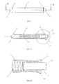
Figure 3 shows a frontal view in isolation of the subset of retractable pins according to the invention. -
Figure 3a shows a sectional view of the subset of retractable pins according to the invention, along axis D-D as defined inFigure 3 . -
Figure 3b is an enlarged view of the area marked as E inFigure 3a . The solid arrows each point to a part and the dashed arrows point to a particular aspect of a part. -
Figure 4a shows a sectional view, along axis B-B as defined inFigure 2 , of an assembly according to the invention comprising a sports shoe (30) that is not clipped into a front unit (40) and a gliding or rolling board (20). The central arrow shows the movement from top to bottom of the shoe in order to clip it into the front unit. -
Figure 4b shows a sectional view, along axis B-B as defined inFigure 2 , of an assembly according to the invention comprising a sports shoe (30) in an intermediary clipping in position to the front unit (40) and a gliding or rolling board (20). The central arrow shows the movement from top to bottom of the shoe, and the two lateral arrows show the movement of the pins (3) towards the inside of the shoe, this in an intermediary clipping in stage of the shoe into the front unit. -
Figure 4c shows a sectional view, along axis B-B as defined inFigure 2 , of the assembly comprising a sports shoe (30) in a position clipped into the front unit (40). The lateral arrows show the movement of the pins (3) and the release systems, each comprising the screw (7), the button (8) and the gasket (9), under the action of the spring (2), in a final clipping in stage of the shoe into the front unit. -
Figure 5a shows a three-dimensional view ofvariant 1 of the front unit in the "walking" position. The solid arrows each point to a part and the dashed arrows point to a particular aspect of a part. -
Figure 5b shows a three-dimensional view ofvariant 1 of the front unit in the "downhill" position. The large arrows show the direction of movement of the stirrups (10) for adoption of the "downhill" position. The solid arrows each point to a part and the dashed arrows point to a particular aspect of a part. -
Figure 5c shows a sectional view of the vertical part ofvariant 1 of the front unit in the "walking" position. The solid arrows each point to a part and the dashed arrows point to a particular aspect of a part. -
Figure 5d shows a sectional view of the vertical part ofvariant 1 of the front unit in the "downhill" position. The large vertical arrow shows the direction of movement of the stirrup (10) for adoption of the "downhill" position, and the large horizontal arrow shows the movement of the release system during adoption of the "downhill" position. The solid arrows each point to a part and the dashed arrows point to a particular aspect of a part. -
Figure 6a shows a three-dimensional view ofvariant 2 of the front unit in the "walking" position. The solid arrows each point to a part and the dashed arrows point to a particular aspect of a part. -
Figure 6b shows a three-dimensional view ofvariant 2 of the front unit in the "downhill" position. The large arrows show the direction of movement of the slider (11) for adoption of the "downhill" position. The solid arrows each point to a part and the dashed arrows point to a particular aspect of a part. -
Figure 6c shows a sectional view of the vertical part ofvariant 2 of the front unit in the "walking" position. The solid arrows each point to a part and the dashed arrows point to a particular aspect of a part. -
Figure 6d shows a sectional view of the vertical part ofvariant 2 of the front unit in the "downhill" position. The large vertical arrow shows the direction of movement of the slider (11) for adoption of the "downhill" position and the horizontal arrow shows the movement of the release system during adoption of the "downhill" position. The solid arrows each point to a part and the dashed arrows point to a particular aspect of a part. - The invention can be carried out according to an embodiment described below. The binding comprises two distinct assemblies:
- according to
Figures 2a ,2b ,3, 3a and 3b , an assembly called "retractable pins", which is integrated into the front end of the shoe. This assembly comprises a sleeve (1) made from a hard material and threaded into each of its extremities, a spring (2) placed into the sleeve (1), two bushings (4) connected by screwing into each extremity of the sleeve (1), and two pins (3) that each slide into a pivot joint sliding at least 1.5 mm into the bushing (4). The spring (2) exerts an axial force on the two pins (3) acting to separate them. The sleeve (1) may be connected by either gluing, pressing or screwing into a hole crossing the width of the front end of the shoe along an axis transverse to the direction of walking and approximately parallel to the sole of the shoe. The spring (2) may be mounted with a pretension force and its compressive movement from the pretensioned state to the point of maximum compression is at least equal to 3 mm. The bushing (4), made from a hard material, may have a collar capable of engaging with the recess (6) of a front unit, may have a transverse groove on the collar enabling the connection of a clamping device, may be threaded on the exterior diameter, and may comprise a smooth central axial hole sized with a minimum clearance to ensure the sliding of the pin (3). The bushing (4) is preferably connected by screwing it into the sleeve (1) until the collar is in contact with the shell of the shoe (30). The end of the pin (3) on the exterior side of the shoe may comprise a fillet radius between the end and the cylindrical part. The other side of the pin may comprise a male spigot over which the end of the spring is slotted. Stopping movement of the pin from the interior to the exterior of the shoe can be ensured by a collar machined onto the pin, which contacts the bushing (4). - According to
Figures 1, 1a ,2, 2a and2b , an assembly (40) called the "front unit", connected by screwing onto the gliding or rolling device (20) comprises a rigid frame (5), two recesses (6), and two release systems, each preferably comprising a button (8), a screw (7) and a gasket (9). The U-shaped frame (5) may comprise 4 countersunk holes on its base offering the option of screwing it onto the gliding or rolling device (20); its vertical parts are preferably narrower than the sole and may comprise, at their extremity, a groove serving as a guide for the pins (3) during the clipping of the sports shoe into the front unit (40); a concave-shaped partial boss situated below each recess (6) preferably forms a mechanical stop in order to prevent movement of the bushing (4) during the clipping in of the sports shoe (30) into the front unit (40). The recess (6) may be drilled to a slightly larger diameter than that of the pin (3) to enable insertion of the latter into the recess (6). The release system may contained by its mounting in the recess (6), but can slide a distance of at least 1.5 mm on its axis, the assembly serving to push the pins (3) towards the inside of the shoe when the user presses on the buttons (8), with the aim of releasing the shoe (30) from the front unit (40). - As can be seen in
Figures 2b and4c , when the sports shoe (30) is clipped in and the pins (3) are received within the recesses (6), the collar (60) contacts the upper side of the partial boss (70) such that the partial boss (70) supports the weight of the shoe and the user during walking and/or downhill. Thus the weight of shoe and the user is at least partially carried by collar (60) such that forces applied to the pins (3) in a direction transverse to the axis of the pins (3) are reduced. Preferably the upper side of the partial boss (70) as a concave shape corresponding to the outer convex shape of the collar (60) such that the collar (60) fits into the concave shape of the boss (70) and is reliably hold and supported even if the the collar rotates according to the rotation of the shoe about the axis of the pins (3) during walking. - In its basic version, the front unit sub-assembly does not have a safe unclipping system for falls and can only be unclipped manually. The safety system for downhill skiing described herein gives the option of unclipping in the event the user falls. This system is activated by the user for going down a slope and when the shoe is clipped into the front unit. The front unit is said to be in the "downhill" position when this safety system is activated and in the "walking" position when it is deactivated. The principle of this safety system relies on a part integrated into the front unit which, when the user moves it, reduces the length of penetration of the pins (3) into the recess (6). When the front unit is in the "walking" position, the pin (3) fully protrudes into the recess (6), and when it is in the "downhill" position, the pin (3) only partially protrudes, approximately halfway. In the "downhill" position, the partial protrusion of the pins (3) in the recesses (6), combined with the presence of a fillet radius (90) on the extremity of the pins (3), enables unclipping of the shoe in case of significant twisting or upward force. The force needed for triggering is set by the stiffness of the spring (2).
- There are two variants for the adoption of the "downhill" position:
-
variant 1, according toFigures 5a, 5b, 5c and 5d , comprises a stirrup (10) made of spring wire fixed into 2 holes in a pivot joint on each vertical part of the frame (5a), which can be turned by the user towards the bottom to activate the "walking" position, and towards the top to activate the "downhill" position whereby the stirrup clips onto the button (8a) which comprises a cavity (100) capable of receiving the stirrup (10), which has the effect of pushing back the release system and therefore the pin (3). In order for the "downhill" position to be fully activated, all stirrups (10) must be in the high position. -
variant 2, according toFigures 6a, 6b, 6c and 6d , comprising a slider (11) placed on each vertical part of the frame (5b), which can be moved by the user towards the bottom to activate the "walking" position, and towards the top to activate the "downhill" position whereby the slider clips onto the button (8a) which comprises a cavity (100) capable of receiving the slider (11), which has the effect of pushing back the release system and therefore the pin (3). In order for the "downhill" position to be fully activated, all the sliders (11) must be in the high position.
Claims (15)
- A front unit (40) of a binding for holding a sports shoe on a gliding or rolling device (20), comprising- a frame (5) having a recess (6) in a vertical portion for receiving a pin (3) projecting laterally from the sports boot,- a release system (7, 8) housed in the recess (6) of the frame (5) and movable within the recess along the axis of the recess to push the pin (3) towards the boot in order to release the shoe (30) from the front unit (40).
- The front unit (40), preferably according to claim 1, characterised in that it comprises a rigid U-shaped frame (5), a recess (6) on each of the vertical parts of the frame (5) capable of engaging with the pin (3) of the shoe (30), and a release system embedded in each recess (6), said release system being able to move at least 1.5 mm along the axis of the recess (6) and preferably comprises a screw (7), a button (8) and a gasket (9).
- The front unit (40) according to at least one of claims 1 and 2, characterised in that the frame (5) comprises, on one or the extremity of each of its vertical parts, a groove (80) in the form of a sloping ramp so as to guide and push the pin (3) towards the interior of the shoe (30) during movement from top to the bottom of the said shoe in an intermediary phase of clipping into the said front unit.
- The front unit (40) according to at least one of the claims 1 to 3, characterised in that the frame (5) comprises a partial boss (70) on one or each of its vertical parts and below the recess (6) capable of engaging with a collar (60) of a bushing (40), or with a boss of a sports shoe, whose function is to stop the vertical movement from top to bottom of the shoe (30) during its clipping into the said front unit, so that the pin (3) is correctly positioned for insertion into the recess (6); the partial boss (70) preferably being concave or flat in shape.
- The front unit (40) according to at least one of claims 1 to 4, characterised in that it comprises a safety system for going downhill enabling, when it is activated, the releasing of the shoe from the said front unit if the user accidentally falls, wherein the safety system comprises a mechanism which enables the reduction of the length of penetration of the pins (3) into the recesses (6) when the sports shoe is clipped into the said front unit.
- The front unit according to the claim 5, characterised in that the safety system for going downhill comprises a bracket (10) placed on each of the vertical parts of the frame (5a), being able to pivot around an axis that is approximately parallel to the direction of walking and to the gliding or rolling device, and being able to be arrested into a cavity (100) of the button (8a) when it is in the downhill position or the high position, in which said bracket extends to push back the button (8a) towards the interior of the shoe (30), thus reducing the protruding length of the pin (3) into the recess (6).
- The front unit according to claim 5, characterised in that the safety system for going downhill comprises a slider (11) placed on each of the vertical parts of the frame (5b), being able to slide the length of or along the vertical part of the frame (5b), fitted with a sloping ramp (110) and being able to be slotted into a cavity (100) of the button (8a) when it is in the downhill position or the high position, in which the said slider stretches to push back the button (8a) towards the interior of the shoe (30), thus reducing the protruding length of the pin (3) into the recess (6).
- The front unit according to at least one of the preceding claims, characterised in that the front unit can be set to- a walking position suitable for walking, in which the release system allows a penetration of a pin (3) of a sports shoe (30) into the recess (6) according to a first predetermined depth of the recess (6),- a downhill position suitable for downhill, in which the release system reduces the penetration length of the pin (3) into the recess (6) by reducing the depth of the recess (6) to a second predetermined depth smaller than the first predetermined depth, and- a release position suitable for stepping into or out of the binding, in which the release system further reduces the depth of the recess (6) until the pin (3) is released from the recess (6).
- The front unit (40) according to claim 8, characterised in further comprising a locking mechanism (10; 11) for locking the release system in the downhill position.
- A retractable pins device, capable of being housed within a sports shoe, comprising two pins (3) each adapted to be inserted into a recess (6) of a front unit (40), characterised in that it comprises two pins (3) that are each able to slide at least 1.5 mm into a bushing (4), and a spring (2) which acts to separate the two pins (3).
- The retractable pins device according to claim 10, characterised in that the bushing (4) comprises a collar (60) capable of engaging with the partial boss (70) of a front unit (40).
- The retractable pins device according to claim 10 or claim 11, characterised in that the pin (3) comprises a rounding (90) or a chamfer between its cylindrical part and its extremity on the exterior side of the shoe (30), said rounding or chamfer being capable of engaging with a recess (6) of a front unit (40) and having as its function the facilitation of the insertion of the pin (3) into the recess (6) and enabling safe unclipping of a variant of the front unit fitted with a safety system for going downhill.
- A sports shoe comprising on each of its lateral front parts, a pin (3) capable of insertion into a recess (6) of a front unit (40) and being able to slide at least 1.5 mm along its own axis, characterised in that it comprises a retractable pins device according to at least one of the preceding claims.
- A sports shoe according to claim 13, characterised in that it comprises, on each of its lateral front parts, a boss capable of engaging with the partial boss (70) of a front unit (40).
- An assembly comprising- a front unit (40) according to at least one of claims 1 to 9, wherein the frame (5) comprises a partial boss (70) on each of its vertical parts and below the recess (6), and- a retractable pins device according to at least one of claims 10 to 12, wherein the bushing (4) comprises a collar (60) on each of opposite sides of the bushing (4),wherein when the retractable pins device is clipped in and the pins (3) are received within the recesses (6), the collars (60) contact the upper side of the partial bosses (70).
Applications Claiming Priority (1)
| Application Number | Priority Date | Filing Date | Title |
|---|---|---|---|
| FR1401140A FR3021228A1 (en) | 2014-05-20 | 2014-05-20 | FRONT STOP FIXING SKI HIKING |
Publications (2)
| Publication Number | Publication Date |
|---|---|
| EP2946818A1 true EP2946818A1 (en) | 2015-11-25 |
| EP2946818B1 EP2946818B1 (en) | 2017-11-15 |
Family
ID=52465389
Family Applications (1)
| Application Number | Title | Priority Date | Filing Date |
|---|---|---|---|
| EP15168446.1A Active EP2946818B1 (en) | 2014-05-20 | 2015-05-20 | Front unit for a binding device and retractable pins device |
Country Status (4)
| Country | Link |
|---|---|
| US (1) | US9308433B2 (en) |
| EP (1) | EP2946818B1 (en) |
| DE (1) | DE202015009539U1 (en) |
| FR (1) | FR3021228A1 (en) |
Cited By (8)
| Publication number | Priority date | Publication date | Assignee | Title |
|---|---|---|---|---|
| EP3323476A1 (en) * | 2016-11-21 | 2018-05-23 | Salewa Sport AG | Touring binding for mounting to a glide board |
| DE102018209090A1 (en) | 2018-06-07 | 2019-12-12 | Salewa Sport Ag | Front unit for a slide board binding |
| IT202000012502A1 (en) * | 2020-05-27 | 2021-11-27 | Atk Sports S R L | FRONT INSERT FOR SKI MOUNTAINEERING BOOTS, FOR ATTACHING THE BOOT TO A SKI MOUNTAINEERING BINDING |
| DE102015223117B4 (en) | 2015-11-23 | 2022-01-05 | Salewa Sport Ag | Touring binding with a control body to limit the penetration depth |
| WO2022149985A1 (en) * | 2021-01-08 | 2022-07-14 | Rottefella As | A part of a binding system |
| WO2022231437A1 (en) * | 2021-04-30 | 2022-11-03 | Rottefella As | A ski binding with inclined insertion, a ski shoe, a ski binding system and a method for attaching ski shoes |
| DE102023136147A1 (en) * | 2023-12-20 | 2025-06-26 | 5Ive Sports Gmbh | Adapter device for attaching a ski boot to a touring ski binding |
| US12501964B2 (en) | 2021-11-25 | 2025-12-23 | Rottefella As | Assembly for anchorage of a binding part in a ski shoe |
Families Citing this family (5)
| Publication number | Priority date | Publication date | Assignee | Title |
|---|---|---|---|---|
| NO342268B1 (en) * | 2016-07-01 | 2018-04-30 | Rottefella As | Attach mechanism |
| DE102017120701A1 (en) * | 2017-09-07 | 2019-03-07 | Marker Deutschland Gmbh | Ultralight forehead |
| EP3566754B1 (en) * | 2018-05-08 | 2022-08-17 | Fritschi AG - Swiss Bindings | Front skibinding |
| IT201900022008A1 (en) * | 2019-11-25 | 2021-05-25 | Atk Sports S R L | INSERT FOR MOUNTAIN SKI BOOTS, FOR ATTACHING THE BOOT TO A MOUNTAIN SKI BINDING |
| NO348287B1 (en) * | 2021-01-08 | 2024-11-11 | Rottefella As | Release mechanism for ski binding |
Citations (6)
| Publication number | Priority date | Publication date | Assignee | Title |
|---|---|---|---|---|
| US3870327A (en) * | 1971-08-11 | 1975-03-11 | Jr Alois Betschart | Self-releasing ski-binding |
| US3905613A (en) * | 1974-03-14 | 1975-09-16 | Calspan Corp | Ski binding |
| DE3141425C1 (en) * | 1981-10-19 | 1982-11-04 | Heinz 8391 Tiefenbach Beck | Safety binding for skis |
| DE3227237C1 (en) * | 1981-10-19 | 1984-01-26 | Heinz 8391 Tiefenbach Beck | Safety binding for skis |
| EP0199098A2 (en) | 1985-03-25 | 1986-10-29 | Fritz Dipl.-Ing. Barthel | Cross-country ski binding |
| FR2945185A1 (en) | 2009-05-05 | 2010-11-12 | Gignoux Sarl | Fixing insert for fixing sport shoe on sliding or marching board in off-track skiing, has interior stop receiving axle of fixing device in interlocked position, where distance between upper end and stop is less than or equal to four mm |
Family Cites Families (2)
| Publication number | Priority date | Publication date | Assignee | Title |
|---|---|---|---|---|
| AT411018B (en) * | 2001-04-11 | 2003-09-25 | Fischer Gmbh | SKI BINDING FOR CROSS-COUNTRY SKIING AND TOURING SKIING |
| DE102009059968A1 (en) | 2009-12-22 | 2011-06-30 | Ide Kg Des Irsara Daniele & Co | Ski binding for connecting ski shoe with ski for ski tour, has base body with retaining areas for retaining pin sections that protrude from ski shoes in front area, and locking areas for detachably locking pin sections in retaining areas |
-
2014
- 2014-05-20 FR FR1401140A patent/FR3021228A1/en not_active Withdrawn
-
2015
- 2015-05-20 EP EP15168446.1A patent/EP2946818B1/en active Active
- 2015-05-20 US US14/717,175 patent/US9308433B2/en active Active
- 2015-05-20 DE DE202015009539.9U patent/DE202015009539U1/en not_active Expired - Lifetime
Patent Citations (6)
| Publication number | Priority date | Publication date | Assignee | Title |
|---|---|---|---|---|
| US3870327A (en) * | 1971-08-11 | 1975-03-11 | Jr Alois Betschart | Self-releasing ski-binding |
| US3905613A (en) * | 1974-03-14 | 1975-09-16 | Calspan Corp | Ski binding |
| DE3141425C1 (en) * | 1981-10-19 | 1982-11-04 | Heinz 8391 Tiefenbach Beck | Safety binding for skis |
| DE3227237C1 (en) * | 1981-10-19 | 1984-01-26 | Heinz 8391 Tiefenbach Beck | Safety binding for skis |
| EP0199098A2 (en) | 1985-03-25 | 1986-10-29 | Fritz Dipl.-Ing. Barthel | Cross-country ski binding |
| FR2945185A1 (en) | 2009-05-05 | 2010-11-12 | Gignoux Sarl | Fixing insert for fixing sport shoe on sliding or marching board in off-track skiing, has interior stop receiving axle of fixing device in interlocked position, where distance between upper end and stop is less than or equal to four mm |
Cited By (16)
| Publication number | Priority date | Publication date | Assignee | Title |
|---|---|---|---|---|
| DE102015223117B4 (en) | 2015-11-23 | 2022-01-05 | Salewa Sport Ag | Touring binding with a control body to limit the penetration depth |
| DE102016222951A1 (en) | 2016-11-21 | 2018-05-24 | Salewa Sport Ag | Touring binding for mounting on a sliding board |
| US10245499B2 (en) | 2016-11-21 | 2019-04-02 | Salewa Sport Ag | Touring binding to be fitted to a gliding board |
| EP3323476A1 (en) * | 2016-11-21 | 2018-05-23 | Salewa Sport AG | Touring binding for mounting to a glide board |
| AT522136A3 (en) * | 2018-06-07 | 2022-12-15 | Salewa Sport Ag | Front unit for a gliding board binding |
| DE102018209090A1 (en) | 2018-06-07 | 2019-12-12 | Salewa Sport Ag | Front unit for a slide board binding |
| AT521330B1 (en) * | 2018-06-07 | 2023-05-15 | Salewa Sport Ag | Front unit for a gliding board binding |
| AT522136B1 (en) * | 2018-06-07 | 2023-05-15 | Salewa Sport Ag | Front unit for a gliding board binding |
| AT521330A3 (en) * | 2018-06-07 | 2022-12-15 | Salewa Sport Ag | Front unit for a gliding board binding |
| IT202000012502A1 (en) * | 2020-05-27 | 2021-11-27 | Atk Sports S R L | FRONT INSERT FOR SKI MOUNTAINEERING BOOTS, FOR ATTACHING THE BOOT TO A SKI MOUNTAINEERING BINDING |
| EP3915423A1 (en) * | 2020-05-27 | 2021-12-01 | Atk Sports S.R.L. | Front insert for a ski mountaineering ski boot, for hooking the ski boot to a ski mountaineering binding |
| WO2022149985A1 (en) * | 2021-01-08 | 2022-07-14 | Rottefella As | A part of a binding system |
| US12576328B2 (en) | 2021-01-08 | 2026-03-17 | Rottefella As | Part of a binding system |
| WO2022231437A1 (en) * | 2021-04-30 | 2022-11-03 | Rottefella As | A ski binding with inclined insertion, a ski shoe, a ski binding system and a method for attaching ski shoes |
| US12501964B2 (en) | 2021-11-25 | 2025-12-23 | Rottefella As | Assembly for anchorage of a binding part in a ski shoe |
| DE102023136147A1 (en) * | 2023-12-20 | 2025-06-26 | 5Ive Sports Gmbh | Adapter device for attaching a ski boot to a touring ski binding |
Also Published As
| Publication number | Publication date |
|---|---|
| EP2946818B1 (en) | 2017-11-15 |
| US9308433B2 (en) | 2016-04-12 |
| FR3021228A1 (en) | 2015-11-27 |
| US20150335987A1 (en) | 2015-11-26 |
| DE202015009539U1 (en) | 2018-03-09 |
Similar Documents
| Publication | Publication Date | Title |
|---|---|---|
| EP2946818B1 (en) | Front unit for a binding device and retractable pins device | |
| US8439389B2 (en) | Toe unit for alpine touring binding | |
| CN103118748B (en) | Touring or cross-country ski binding | |
| EP2281614B1 (en) | Heel piece with two-armed front fork engageable with pins on a boot | |
| US8973924B2 (en) | Device for adjusting the position of the boot support holder in a ski fastening system | |
| US9114306B2 (en) | Braking device for alpine touring ski | |
| US20100257754A1 (en) | Ski-boot with means for actuating corresponding engaging members of ski-touring bindings | |
| US20120104707A1 (en) | Safety binding for skiing | |
| EP2946817B1 (en) | Toe-piece for ski-touring bindings | |
| US20180093162A1 (en) | Mechanism for locking longitudinally a ski-binding on a mounting plate | |
| US10016672B2 (en) | Self-locking binding for telemark ski, touring ski or cross-country ski | |
| US9901806B2 (en) | Automatic heel unit with walking configuration | |
| FR2741543A1 (en) | Binding for cross country ski boot with axle | |
| US9962595B2 (en) | Automatic heel unit with heel support structure | |
| RU2525476C2 (en) | Ski binding | |
| FI126938B (en) | Ski binding for a flexible ski boot | |
| EP2308568A1 (en) | Ski binding toe for touring skiing with an improved locking | |
| US6523852B2 (en) | Step-in snowboard binding | |
| US9220312B2 (en) | Safety ski binding system | |
| US11130045B2 (en) | Fastening device for fastening a boot to a sliding board | |
| JPS63501130A (en) | ski binding | |
| US9192847B2 (en) | Ski brake | |
| US20060108773A1 (en) | Binding device for securing a boot suited to walking to a gliding board |
Legal Events
| Date | Code | Title | Description |
|---|---|---|---|
| REG | Reference to a national code |
Ref country code: DE Ref legal event code: R138 Ref document number: 202015009539 Country of ref document: DE Free format text: GERMAN DOCUMENT NUMBER IS 602015005950 |
|
| PUAI | Public reference made under article 153(3) epc to a published international application that has entered the european phase |
Free format text: ORIGINAL CODE: 0009012 |
|
| AK | Designated contracting states |
Kind code of ref document: A1 Designated state(s): AL AT BE BG CH CY CZ DE DK EE ES FI FR GB GR HR HU IE IS IT LI LT LU LV MC MK MT NL NO PL PT RO RS SE SI SK SM TR |
|
| AX | Request for extension of the european patent |
Extension state: BA ME |
|
| 17P | Request for examination filed |
Effective date: 20160427 |
|
| RBV | Designated contracting states (corrected) |
Designated state(s): AL AT BE BG CH CY CZ DE DK EE ES FI FR GB GR HR HU IE IS IT LI LT LU LV MC MK MT NL NO PL PT RO RS SE SI SK SM TR |
|
| RIC1 | Information provided on ipc code assigned before grant |
Ipc: A63C 9/08 20120101AFI20170327BHEP Ipc: A63C 9/086 20120101ALI20170327BHEP |
|
| GRAP | Despatch of communication of intention to grant a patent |
Free format text: ORIGINAL CODE: EPIDOSNIGR1 |
|
| INTG | Intention to grant announced |
Effective date: 20170529 |
|
| GRAS | Grant fee paid |
Free format text: ORIGINAL CODE: EPIDOSNIGR3 |
|
| GRAA | (expected) grant |
Free format text: ORIGINAL CODE: 0009210 |
|
| AK | Designated contracting states |
Kind code of ref document: B1 Designated state(s): AL AT BE BG CH CY CZ DE DK EE ES FI FR GB GR HR HU IE IS IT LI LT LU LV MC MK MT NL NO PL PT RO RS SE SI SK SM TR |
|
| REG | Reference to a national code |
Ref country code: CH Ref legal event code: EP Ref country code: GB Ref legal event code: FG4D Ref country code: AT Ref legal event code: REF Ref document number: 945693 Country of ref document: AT Kind code of ref document: T Effective date: 20171115 |
|
| REG | Reference to a national code |
Ref country code: IE Ref legal event code: FG4D |
|
| REG | Reference to a national code |
Ref country code: DE Ref legal event code: R096 Ref document number: 602015005950 Country of ref document: DE |
|
| REG | Reference to a national code |
Ref country code: CH Ref legal event code: NV Representative=s name: E. BLUM AND CO. AG PATENT- UND MARKENANWAELTE , CH |
|
| REG | Reference to a national code |
Ref country code: NL Ref legal event code: MP Effective date: 20171115 |
|
| REG | Reference to a national code |
Ref country code: LT Ref legal event code: MG4D |
|
| PG25 | Lapsed in a contracting state [announced via postgrant information from national office to epo] |
Ref country code: NO Free format text: LAPSE BECAUSE OF FAILURE TO SUBMIT A TRANSLATION OF THE DESCRIPTION OR TO PAY THE FEE WITHIN THE PRESCRIBED TIME-LIMIT Effective date: 20180215 Ref country code: FI Free format text: LAPSE BECAUSE OF FAILURE TO SUBMIT A TRANSLATION OF THE DESCRIPTION OR TO PAY THE FEE WITHIN THE PRESCRIBED TIME-LIMIT Effective date: 20171115 Ref country code: ES Free format text: LAPSE BECAUSE OF FAILURE TO SUBMIT A TRANSLATION OF THE DESCRIPTION OR TO PAY THE FEE WITHIN THE PRESCRIBED TIME-LIMIT Effective date: 20171115 Ref country code: NL Free format text: LAPSE BECAUSE OF FAILURE TO SUBMIT A TRANSLATION OF THE DESCRIPTION OR TO PAY THE FEE WITHIN THE PRESCRIBED TIME-LIMIT Effective date: 20171115 Ref country code: SE Free format text: LAPSE BECAUSE OF FAILURE TO SUBMIT A TRANSLATION OF THE DESCRIPTION OR TO PAY THE FEE WITHIN THE PRESCRIBED TIME-LIMIT Effective date: 20171115 Ref country code: LT Free format text: LAPSE BECAUSE OF FAILURE TO SUBMIT A TRANSLATION OF THE DESCRIPTION OR TO PAY THE FEE WITHIN THE PRESCRIBED TIME-LIMIT Effective date: 20171115 |
|
| PG25 | Lapsed in a contracting state [announced via postgrant information from national office to epo] |
Ref country code: HR Free format text: LAPSE BECAUSE OF FAILURE TO SUBMIT A TRANSLATION OF THE DESCRIPTION OR TO PAY THE FEE WITHIN THE PRESCRIBED TIME-LIMIT Effective date: 20171115 Ref country code: BG Free format text: LAPSE BECAUSE OF FAILURE TO SUBMIT A TRANSLATION OF THE DESCRIPTION OR TO PAY THE FEE WITHIN THE PRESCRIBED TIME-LIMIT Effective date: 20180215 Ref country code: GR Free format text: LAPSE BECAUSE OF FAILURE TO SUBMIT A TRANSLATION OF THE DESCRIPTION OR TO PAY THE FEE WITHIN THE PRESCRIBED TIME-LIMIT Effective date: 20180216 Ref country code: LV Free format text: LAPSE BECAUSE OF FAILURE TO SUBMIT A TRANSLATION OF THE DESCRIPTION OR TO PAY THE FEE WITHIN THE PRESCRIBED TIME-LIMIT Effective date: 20171115 Ref country code: RS Free format text: LAPSE BECAUSE OF FAILURE TO SUBMIT A TRANSLATION OF THE DESCRIPTION OR TO PAY THE FEE WITHIN THE PRESCRIBED TIME-LIMIT Effective date: 20171115 |
|
| PG25 | Lapsed in a contracting state [announced via postgrant information from national office to epo] |
Ref country code: EE Free format text: LAPSE BECAUSE OF FAILURE TO SUBMIT A TRANSLATION OF THE DESCRIPTION OR TO PAY THE FEE WITHIN THE PRESCRIBED TIME-LIMIT Effective date: 20171115 Ref country code: CY Free format text: LAPSE BECAUSE OF FAILURE TO SUBMIT A TRANSLATION OF THE DESCRIPTION OR TO PAY THE FEE WITHIN THE PRESCRIBED TIME-LIMIT Effective date: 20171115 Ref country code: DK Free format text: LAPSE BECAUSE OF FAILURE TO SUBMIT A TRANSLATION OF THE DESCRIPTION OR TO PAY THE FEE WITHIN THE PRESCRIBED TIME-LIMIT Effective date: 20171115 Ref country code: CZ Free format text: LAPSE BECAUSE OF FAILURE TO SUBMIT A TRANSLATION OF THE DESCRIPTION OR TO PAY THE FEE WITHIN THE PRESCRIBED TIME-LIMIT Effective date: 20171115 Ref country code: SK Free format text: LAPSE BECAUSE OF FAILURE TO SUBMIT A TRANSLATION OF THE DESCRIPTION OR TO PAY THE FEE WITHIN THE PRESCRIBED TIME-LIMIT Effective date: 20171115 |
|
| REG | Reference to a national code |
Ref country code: DE Ref legal event code: R097 Ref document number: 602015005950 Country of ref document: DE |
|
| PG25 | Lapsed in a contracting state [announced via postgrant information from national office to epo] |
Ref country code: SM Free format text: LAPSE BECAUSE OF FAILURE TO SUBMIT A TRANSLATION OF THE DESCRIPTION OR TO PAY THE FEE WITHIN THE PRESCRIBED TIME-LIMIT Effective date: 20171115 Ref country code: RO Free format text: LAPSE BECAUSE OF FAILURE TO SUBMIT A TRANSLATION OF THE DESCRIPTION OR TO PAY THE FEE WITHIN THE PRESCRIBED TIME-LIMIT Effective date: 20171115 Ref country code: PL Free format text: LAPSE BECAUSE OF FAILURE TO SUBMIT A TRANSLATION OF THE DESCRIPTION OR TO PAY THE FEE WITHIN THE PRESCRIBED TIME-LIMIT Effective date: 20171115 |
|
| PLBE | No opposition filed within time limit |
Free format text: ORIGINAL CODE: 0009261 |
|
| STAA | Information on the status of an ep patent application or granted ep patent |
Free format text: STATUS: NO OPPOSITION FILED WITHIN TIME LIMIT |
|
| 26N | No opposition filed |
Effective date: 20180817 |
|
| PG25 | Lapsed in a contracting state [announced via postgrant information from national office to epo] |
Ref country code: SI Free format text: LAPSE BECAUSE OF FAILURE TO SUBMIT A TRANSLATION OF THE DESCRIPTION OR TO PAY THE FEE WITHIN THE PRESCRIBED TIME-LIMIT Effective date: 20171115 |
|
| REG | Reference to a national code |
Ref country code: BE Ref legal event code: MM Effective date: 20180531 |
|
| PG25 | Lapsed in a contracting state [announced via postgrant information from national office to epo] |
Ref country code: MC Free format text: LAPSE BECAUSE OF FAILURE TO SUBMIT A TRANSLATION OF THE DESCRIPTION OR TO PAY THE FEE WITHIN THE PRESCRIBED TIME-LIMIT Effective date: 20171115 |
|
| REG | Reference to a national code |
Ref country code: IE Ref legal event code: MM4A |
|
| PG25 | Lapsed in a contracting state [announced via postgrant information from national office to epo] |
Ref country code: LU Free format text: LAPSE BECAUSE OF NON-PAYMENT OF DUE FEES Effective date: 20180520 |
|
| PG25 | Lapsed in a contracting state [announced via postgrant information from national office to epo] |
Ref country code: FR Free format text: LAPSE BECAUSE OF NON-PAYMENT OF DUE FEES Effective date: 20180531 Ref country code: IE Free format text: LAPSE BECAUSE OF NON-PAYMENT OF DUE FEES Effective date: 20180520 |
|
| PG25 | Lapsed in a contracting state [announced via postgrant information from national office to epo] |
Ref country code: BE Free format text: LAPSE BECAUSE OF NON-PAYMENT OF DUE FEES Effective date: 20180531 |
|
| GBPC | Gb: european patent ceased through non-payment of renewal fee |
Effective date: 20190520 |
|
| PG25 | Lapsed in a contracting state [announced via postgrant information from national office to epo] |
Ref country code: MT Free format text: LAPSE BECAUSE OF NON-PAYMENT OF DUE FEES Effective date: 20180520 |
|
| PG25 | Lapsed in a contracting state [announced via postgrant information from national office to epo] |
Ref country code: TR Free format text: LAPSE BECAUSE OF FAILURE TO SUBMIT A TRANSLATION OF THE DESCRIPTION OR TO PAY THE FEE WITHIN THE PRESCRIBED TIME-LIMIT Effective date: 20171115 |
|
| PG25 | Lapsed in a contracting state [announced via postgrant information from national office to epo] |
Ref country code: GB Free format text: LAPSE BECAUSE OF NON-PAYMENT OF DUE FEES Effective date: 20190520 |
|
| PG25 | Lapsed in a contracting state [announced via postgrant information from national office to epo] |
Ref country code: PT Free format text: LAPSE BECAUSE OF FAILURE TO SUBMIT A TRANSLATION OF THE DESCRIPTION OR TO PAY THE FEE WITHIN THE PRESCRIBED TIME-LIMIT Effective date: 20171115 |
|
| PG25 | Lapsed in a contracting state [announced via postgrant information from national office to epo] |
Ref country code: HU Free format text: LAPSE BECAUSE OF FAILURE TO SUBMIT A TRANSLATION OF THE DESCRIPTION OR TO PAY THE FEE WITHIN THE PRESCRIBED TIME-LIMIT; INVALID AB INITIO Effective date: 20150520 Ref country code: MK Free format text: LAPSE BECAUSE OF NON-PAYMENT OF DUE FEES Effective date: 20171115 |
|
| PG25 | Lapsed in a contracting state [announced via postgrant information from national office to epo] |
Ref country code: AL Free format text: LAPSE BECAUSE OF FAILURE TO SUBMIT A TRANSLATION OF THE DESCRIPTION OR TO PAY THE FEE WITHIN THE PRESCRIBED TIME-LIMIT Effective date: 20171115 Ref country code: IS Free format text: LAPSE BECAUSE OF FAILURE TO SUBMIT A TRANSLATION OF THE DESCRIPTION OR TO PAY THE FEE WITHIN THE PRESCRIBED TIME-LIMIT Effective date: 20180315 |
|
| REG | Reference to a national code |
Ref country code: AT Ref legal event code: UEP Ref document number: 945693 Country of ref document: AT Kind code of ref document: T Effective date: 20171115 |
|
| PGFP | Annual fee paid to national office [announced via postgrant information from national office to epo] |
Ref country code: CH Payment date: 20220519 Year of fee payment: 8 Ref country code: AT Payment date: 20220523 Year of fee payment: 8 |
|
| P01 | Opt-out of the competence of the unified patent court (upc) registered |
Effective date: 20230511 |
|
| P02 | Opt-out of the competence of the unified patent court (upc) changed |
Effective date: 20230527 |
|
| REG | Reference to a national code |
Ref country code: CH Ref legal event code: PL |
|
| REG | Reference to a national code |
Ref country code: AT Ref legal event code: MM01 Ref document number: 945693 Country of ref document: AT Kind code of ref document: T Effective date: 20230520 |
|
| PG25 | Lapsed in a contracting state [announced via postgrant information from national office to epo] |
Ref country code: LI Free format text: LAPSE BECAUSE OF NON-PAYMENT OF DUE FEES Effective date: 20230531 Ref country code: CH Free format text: LAPSE BECAUSE OF NON-PAYMENT OF DUE FEES Effective date: 20230531 Ref country code: AT Free format text: LAPSE BECAUSE OF NON-PAYMENT OF DUE FEES Effective date: 20230520 |
|
| PGFP | Annual fee paid to national office [announced via postgrant information from national office to epo] |
Ref country code: DE Payment date: 20250428 Year of fee payment: 11 |
|
| PGFP | Annual fee paid to national office [announced via postgrant information from national office to epo] |
Ref country code: IT Payment date: 20250527 Year of fee payment: 11 |