EP2946717A1 - Scanning endoscope - Google Patents
Scanning endoscope Download PDFInfo
- Publication number
- EP2946717A1 EP2946717A1 EP14823239.0A EP14823239A EP2946717A1 EP 2946717 A1 EP2946717 A1 EP 2946717A1 EP 14823239 A EP14823239 A EP 14823239A EP 2946717 A1 EP2946717 A1 EP 2946717A1
- Authority
- EP
- European Patent Office
- Prior art keywords
- optical fiber
- light
- light emission
- scanning
- actuator
- Prior art date
- Legal status (The legal status is an assumption and is not a legal conclusion. Google has not performed a legal analysis and makes no representation as to the accuracy of the status listed.)
- Withdrawn
Links
- 239000013307 optical fiber Substances 0.000 claims abstract description 110
- 238000005286 illumination Methods 0.000 claims abstract description 44
- 230000005540 biological transmission Effects 0.000 claims abstract description 36
- 230000004044 response Effects 0.000 claims abstract description 10
- 239000000835 fiber Substances 0.000 description 19
- 238000003780 insertion Methods 0.000 description 11
- 230000037431 insertion Effects 0.000 description 11
- 238000000034 method Methods 0.000 description 4
- 238000001514 detection method Methods 0.000 description 3
- 230000003287 optical effect Effects 0.000 description 3
- 230000010355 oscillation Effects 0.000 description 3
- PXHVJJICTQNCMI-UHFFFAOYSA-N Nickel Chemical compound [Ni] PXHVJJICTQNCMI-UHFFFAOYSA-N 0.000 description 2
- MCMNRKCIXSYSNV-UHFFFAOYSA-N Zirconium dioxide Chemical compound O=[Zr]=O MCMNRKCIXSYSNV-UHFFFAOYSA-N 0.000 description 2
- 239000000853 adhesive Substances 0.000 description 1
- 230000001070 adhesive effect Effects 0.000 description 1
- 239000000919 ceramic Substances 0.000 description 1
- 239000002131 composite material Substances 0.000 description 1
- 230000006870 function Effects 0.000 description 1
- 239000002184 metal Substances 0.000 description 1
- 229910052751 metal Inorganic materials 0.000 description 1
- 238000012986 modification Methods 0.000 description 1
- 230000004048 modification Effects 0.000 description 1
- 229910052759 nickel Inorganic materials 0.000 description 1
Images


Classifications
-
- A—HUMAN NECESSITIES
- A61—MEDICAL OR VETERINARY SCIENCE; HYGIENE
- A61B—DIAGNOSIS; SURGERY; IDENTIFICATION
- A61B1/00—Instruments for performing medical examinations of the interior of cavities or tubes of the body by visual or photographical inspection, e.g. endoscopes; Illuminating arrangements therefor
- A61B1/06—Instruments for performing medical examinations of the interior of cavities or tubes of the body by visual or photographical inspection, e.g. endoscopes; Illuminating arrangements therefor with illuminating arrangements
- A61B1/07—Instruments for performing medical examinations of the interior of cavities or tubes of the body by visual or photographical inspection, e.g. endoscopes; Illuminating arrangements therefor with illuminating arrangements using light-conductive means, e.g. optical fibres
-
- A—HUMAN NECESSITIES
- A61—MEDICAL OR VETERINARY SCIENCE; HYGIENE
- A61B—DIAGNOSIS; SURGERY; IDENTIFICATION
- A61B1/00—Instruments for performing medical examinations of the interior of cavities or tubes of the body by visual or photographical inspection, e.g. endoscopes; Illuminating arrangements therefor
- A61B1/00064—Constructional details of the endoscope body
- A61B1/00071—Insertion part of the endoscope body
- A61B1/0008—Insertion part of the endoscope body characterised by distal tip features
- A61B1/00096—Optical elements
-
- A—HUMAN NECESSITIES
- A61—MEDICAL OR VETERINARY SCIENCE; HYGIENE
- A61B—DIAGNOSIS; SURGERY; IDENTIFICATION
- A61B1/00—Instruments for performing medical examinations of the interior of cavities or tubes of the body by visual or photographical inspection, e.g. endoscopes; Illuminating arrangements therefor
- A61B1/00112—Connection or coupling means
- A61B1/00121—Connectors, fasteners and adapters, e.g. on the endoscope handle
- A61B1/00126—Connectors, fasteners and adapters, e.g. on the endoscope handle optical, e.g. for light supply cables
-
- A—HUMAN NECESSITIES
- A61—MEDICAL OR VETERINARY SCIENCE; HYGIENE
- A61B—DIAGNOSIS; SURGERY; IDENTIFICATION
- A61B1/00—Instruments for performing medical examinations of the interior of cavities or tubes of the body by visual or photographical inspection, e.g. endoscopes; Illuminating arrangements therefor
- A61B1/00131—Accessories for endoscopes
- A61B1/00133—Drive units for endoscopic tools inserted through or with the endoscope
-
- A—HUMAN NECESSITIES
- A61—MEDICAL OR VETERINARY SCIENCE; HYGIENE
- A61B—DIAGNOSIS; SURGERY; IDENTIFICATION
- A61B1/00—Instruments for performing medical examinations of the interior of cavities or tubes of the body by visual or photographical inspection, e.g. endoscopes; Illuminating arrangements therefor
- A61B1/00163—Optical arrangements
- A61B1/00172—Optical arrangements with means for scanning
-
- A—HUMAN NECESSITIES
- A61—MEDICAL OR VETERINARY SCIENCE; HYGIENE
- A61B—DIAGNOSIS; SURGERY; IDENTIFICATION
- A61B1/00—Instruments for performing medical examinations of the interior of cavities or tubes of the body by visual or photographical inspection, e.g. endoscopes; Illuminating arrangements therefor
- A61B1/06—Instruments for performing medical examinations of the interior of cavities or tubes of the body by visual or photographical inspection, e.g. endoscopes; Illuminating arrangements therefor with illuminating arrangements
- A61B1/0661—Endoscope light sources
- A61B1/0669—Endoscope light sources at proximal end of an endoscope
-
- A—HUMAN NECESSITIES
- A61—MEDICAL OR VETERINARY SCIENCE; HYGIENE
- A61B—DIAGNOSIS; SURGERY; IDENTIFICATION
- A61B5/00—Measuring for diagnostic purposes; Identification of persons
- A61B5/0059—Measuring for diagnostic purposes; Identification of persons using light, e.g. diagnosis by transillumination, diascopy, fluorescence
- A61B5/0062—Arrangements for scanning
-
- H—ELECTRICITY
- H10—SEMICONDUCTOR DEVICES; ELECTRIC SOLID-STATE DEVICES NOT OTHERWISE PROVIDED FOR
- H10N—ELECTRIC SOLID-STATE DEVICES NOT OTHERWISE PROVIDED FOR
- H10N30/00—Piezoelectric or electrostrictive devices
- H10N30/20—Piezoelectric or electrostrictive devices with electrical input and mechanical output, e.g. functioning as actuators or vibrators
- H10N30/202—Piezoelectric or electrostrictive devices with electrical input and mechanical output, e.g. functioning as actuators or vibrators using longitudinal or thickness displacement combined with bending, shear or torsion displacement
- H10N30/2023—Piezoelectric or electrostrictive devices with electrical input and mechanical output, e.g. functioning as actuators or vibrators using longitudinal or thickness displacement combined with bending, shear or torsion displacement having polygonal or rectangular shape
Definitions
- the present invention relates to a scanning endoscope, and more particularly to a scanning endoscope that acquires an image by scanning an object.
- the above-described scanning endoscope is configured, for example, to cause an actuator, which is mounted to the light-emission-side end portion of an illumination fiber that transmits illumination light emitted from a light source portion, to vibrate. This vibration causes the illumination fiber to oscillate in a predetermined scanning pattern, thereby enabling scanning of an object in a scanning range corresponding to the predetermined scanning pattern.
- Japanese Patent Application Laid-Open Publication No. 2009-212519 discloses a scanning fiber endoscope having a configuration similar to that of the above-described scanning endoscope.
- the scanning endoscope having the configuration as described above has the following problem. That is, the vibration of the actuator or disturbance causes oscillation of a part of the illumination fiber, the part being located on a proximal end side of the illumination fiber with respect to the actuator mounting position (the part does not directly relate to the scanning of the object), and such oscillation problematically leads to unstable oscillation state of another part of the illumination fiber, the other part being located on a distal end side of the illumination fiber with respect to the actuator mounting position (the other part directly relates to the scanning of the object), for example.
- the Japanese Patent Application Laid-Open Publication No. 2009-212519 does not specifically mention any method for solving the above-described problem. Therefore, the scanning fiber endoscope disclosed in the Japanese Patent Application Laid-Open Publication No. 2009-212519 still has a problem to be solved, which corresponds to the above-described problematic point, that is, it is not possible to stably perform scanning of the object in the originally intended scanning pattern.
- the present invention has been achieved in view of the above-described circumstances, and an object of the present invention is to provide a scanning endoscope that is capable of performing scanning of an object in a more stable manner than that in conventional scanning endoscopes.
- a scanning endoscope includes: a light-guiding portion configured to guide illumination light for illuminating an object through an optical fiber and emit the guided illumination light from a light emission surface positioned on a distal end side of the optical fiber; an actuator portion configured to vibrate in response to a supply of a driving signal for scanning the object in a predetermined scanning pattern, to thereby cause a part of the optical fiber to oscillate, the part of the optical fiber being located in a light emission portion which includes the light emission surface; a holding member configured to be able to hold the part of the optical fiber located in the light emission portion and the actuator portion, in a cantilevered manner; and a vibration-absorbing member provided at least on a circumference of a portion of the optical fiber adjacent to the holding member, the portion being included in another part of the optical fiber which is located in a light transmission portion which does not include the light emission surface.
- a scanning endoscope includes: a light-guiding portion configured to guide illumination light for illuminating an object through an optical fiber and emit the guided illumination light from a light emission surface positioned on a distal end side of the optical fiber; an actuator portion configured to vibrate in response to a supply of a driving signal for scanning the object in a predetermined scanning pattern, to thereby cause a part of the optical fiber to oscillate, the part of the optical fiber being located in a light emission portion which includes the light emission surface; and a holding member configured to be able to hold the part of the optical fiber located in the light emission portion and the actuator portion, in a cantilevered manner, wherein the optical fiber is formed such that at least an outer diameter of a portion of the optical fiber adjacent to the holding member, the portion being included in another part of the optical fiber located in a light transmission portion which does not include the light emission surface, and an outer diameter of the part of the optical fiber which is located in the light emission portion are different from each other.
- FIGS. 1 to 4 relate to the first embodiment of the present invention.
- FIG 1 illustrates a configuration of a main part of a scanning endoscope system including a scanning endoscope according to an embodiment of the present invention.
- a scanning endoscope system 1 includes, as shown in FIG. 1 for example, a scanning endoscope 2 configured to be insertable into a body cavity of a subject to be examined, a main body apparatus 3 connected to the scanning endoscope 2, and a monitor 4 connected to the main body apparatus 3.
- the scanning endoscope 2 includes an insertion portion 11 formed in an elongated cylindrical shape and having flexibility.
- the insertion portion 11 includes, at the proximal end portion thereof, a connector, for example, not shown, for detachably connecting the scanning endoscope 2 to the main body apparatus 3.
- FIG. 2 illustrates one example of a configuration of a distal end portion of the scanning endoscope according to the first embodiment.
- the insertion portion 11 includes, at a distal end portion 11 A, a light-emission-side end portion of a light-guiding portion for illumination 12 configured to guide illumination light supplied from the main body apparatus 3 with an optical fiber 51 to allow the illumination light to emit from a light emission surface positioned on the distal end side of the optical fiber 51, a light condensing optical system 14 configured to condense the illumination light emitted from the light-guiding portion for illumination 12, the light condensing optical system 14 being arranged so as to be fixed by a lens frame 61, and an actuator portion 15 provided at the light-emission-side end portion of the light-guiding portion for illumination 12 and configured to vibrate in response to a driving signal supplied through a plurality of signal lines 45 connected to the main body apparatus 3,to thereby enable a part of the optical fiber 51 which is located in the light emission portion 12A of the light-guiding
- the distal end portion 11A of the insertion portion 11 includes a light-incident-side end portion of a light-guiding portion for light reception 13 that receives return light from the object to guide the received return light to the main body apparatus 3.
- the optical fiber 51 is formed by including a core (not shown) which is a propagation path of the illumination light supplied from the main body apparatus 3 and a clad (not shown) covering around the core.
- a part of the optical fiber 51 located in the light emission portion 12A including the light emission surface is disposed in the state not covered with a vibration-absorbing member 47 and a fiber outer cover 48. Furthermore, in the light-emission-side end portion of the light-guiding portion for illumination 12, another part of the optical fiber 51 located in the light transmission portion 12B which does not include the light emission surface is disposed in the state covered with the vibration-absorbing member 47 and the fiber outer cover 48.
- Each of the lenses 14a and 14b of the light condensing optical system 14 are configured to have a positive refractive power.
- the part of the optical fiber 51 which is located in the light emission portion 12A is arranged so as to penetrate through the distal end portion 11A of the insertion portion 11, and the distal end portion 11A of the insertion portion 11 is provided with: a ferrule 41 including on the outer surface thereof the actuator portion 15; a housing 43 made of a hollow cylindrical-shaped metal or the like; a holding member 44 which holds the actuator portion 15 and the ferrule 41 in the housing 43; the plurality of signal lines 45; the vibration-absorbing member 47; and the fiber outer cover 48.
- FIG. 3 is a cross-sectional view taken along the III-III line in FIG. 2 .
- the ferrule 41 as a joint member is arranged between the optical fiber 51 and the actuator portion 15.
- the ferrule 41 is made of zirconia (ceramic) or nickel, etc., for example.
- the ferrule 41 is formed as a quadrangular prism and includes side surfaces 42a and 42c which are vertical to the X-axis direction and side surfaces 42b and 42d which are vertical to the Y-axis direction.
- the part of the optical fiber 51 which is located on the proximal end side of the light emission portion 12A is fixedly arranged.
- the ferrule 41 may be formed in another shape other than quadrangular prism, as long as the ferrule has a rectangular prism shape.
- the actuator portion 15 includes an actuator 15a arranged along the side surface 42a, an actuator 15b arranged along the side surface 42b, an actuator 15c arranged along the side surface 42c, and an actuator 15d arranged along the side surface 42d.
- the actuators 15a and 15c are, for example, made of piezoelectric elements and configured to vibrate in response to a driving signal outputted from an amplifier 35 through a D/A converter 34a of a driver unit 22.
- the actuators 15b and 15d are, for example, made of piezoelectric elements and configured to vibrate in response to a driving signal outputted from the amplifier 35 through the D/A converter 34b of the driver unit 22.
- the housing 43 is formed so as to have an inner diameter enough to cover around the light-emission-side end portion of the light-guiding portion for illumination 12, the actuator portion 15 and the ferrule 41.
- the distal end side of the housing 43 is coupled to a predetermined position on the proximal end side of the lens frame 61.
- the holding member 44 is formed such that a plane (hereinafter, also referred to as the XY plane), which is perpendicular to a longitudinal direction (hereinafter, also referred to as the Z-axis direction) of the light-guiding portion for illumination 12, has substantially a ring shape, for example.
- the holding member 44 is mounted in the state where the surface (side surface) parallel to the Z-axis direction is brought into contact with the inner circumferential surface of the housing 43.
- the holding member 44 includes a hole portion into which a ferrule proximal end portion 46, which is located at a position away from the arranging position of the actuator portion 15 toward the proximal end side, can be fitted.
- the holding member 44 includes an insertion hole through which the plurality of signal lines 45 can be inserted. That is, with the configuration of the holding member 44 as described above, the ferrule proximal end portion 46 of the ferrule 41 is fitted in the hole portion of the holding member 44, and thereby the part of the optical fiber 51 which is located in the light emission portion 12A, the actuator portion 15 connected to the plurality of signal lines 45, and the ferrule 41 are held in a cantilevered manner in the internal space of the housing 43.
- the vibration-absorbing member 47 is, for example, made of an adhesive or a soft rubber and the like, and formed so as to cover a circumference of a portion of the optical fiber adjacent to the holding member 44 (or the ferrule proximal end portion 46 fitted into the hole portion of the holding portion 44), the portion being included in the part of the optical fiber 51 which is located in the light transmission portion 12B.
- the fiber outer cover 48 is formed so as to cover a circumference of at least one portion located on the proximal end side with respect to the portion covered with the vibration-absorbing member 47, the one portion being included in the part of the optical fiber 51 which is located in the light transmission portion 12B.
- the part of the optical fiber 51 from the light emission surface to the inside of the ferrule 41 is located in the light emission portion 12A, and the other part of the optical fiber 51, which extends outward (toward the proximal end side) from the ferrule proximal end portion 46, is located in the light transmission portion 12B.
- the light emission portion 12A and the light transmission portion 12B are applied not only to the distal end portion 11A but also to a distal end portion 11B to be described later.
- the main body apparatus 3 includes a light source unit 21, the driver unit 22, a detection unit 23, a memory 24, and a controller 25.
- the light source unit 21 includes a function as a light source portion that supplies illumination light for illuminating an object. Specifically, as shown in FIG. 1 , the light source unit 21 includes a light source 31a, a light source 31b, a light source 31c, and a multiplexer 32.
- the light source 31a includes a laser light source, etc., for example, and configured to emit light in the red wavelength band (hereinafter, also referred to as R light) to the multiplexer 32, when turned on under the control by the controller 25.
- R light red wavelength band
- the light source 31b includes a laser light source, etc., for example, and configured to emit light in the green wavelength band (hereinafter, also referred to as G light) to the multiplexer 32, when turned on under the control by the controller 25.
- G light green wavelength band
- the light source 31c includes a laser light source, etc., for example, and configured to emit light in the blue wavelength band (hereinafter, also referred to as B light) to the multiplexer 32, when turned on under the control by the controller 25.
- B light blue wavelength band
- the multiplexer 32 is configured to multiplex the R light emitted from the light source 31a, the G light emitted from the light source 31b, and the B light emitted from the light source 31c and supply the multiplexed light onto the light incident surface of the light-guiding portion for illumination 12.
- the driver unit 22 includes a signal generator 33, D/A converters 34a, 34b, and the amplifier 35.
- the signal generator 33 is configured to generate a driving signal for causing the light-guiding portion for illumination 12 to oscillate, and configured to output the driving signal to the D/A converters 34a, 34b under the control by the controller 25.
- Each of the D/A converters 34a and 34b is configured to convert a digital driving signal outputted from the signal generator 33 into an analog driving signal to output the analog driving signal to the amplifier 35.
- the amplifier 35 is configured to amplify the driving signal outputted from each of the D/A converters 34a and 34b, to output the amplified driving signal to the actuator portion 15.
- the detection unit 23 includes a demultiplexer 36, detectors 37a, 37b, and 37c, and A/D converters 38a, 38b, and 38c.
- the demultiplexer 36 includes a dichroic mirror and the like and configured to separate the return light emitted from the light emission surface of the light-guiding portion for light reception 13 into light of each color component of R (red), G (green), and B (blue), and emit the separated light to each of the detectors 37a, 37b and 37c.
- the detector 37a is configured to detect the intensity of the R light outputted from the demultiplexer 36, generate an analog R signal corresponding to the detected intensity of the R light, and output the generated analog R signal to the A/D converter 38a.
- the detector 37b is configured to detect the intensity of the G light outputted from the demultiplexer 36, generate an analog G signal corresponding to the detected intensity of the G light, and output the generated analog G signal to the A/D converter 38b.
- the detector 37c is configured to detect the intensity of the B light outputted from the demultiplexer 36, generate an analog B signal corresponding to the detected intensity of the B light, and output the generated analog B signal to the A/D converter 38c.
- the A/D converter 38a is configured to convert the analog R signal outputted from the detector 37a into a digital R signal, to output the digital R signal to the controller 25.
- the A/D converter 38b is configured to convert the analog G signal outputted from the detector 37b into a digital G signal, to output the digital G signal to the controller 25.
- the A/D converter 38c is configured to convert the analog B signal outputted from the detector 37c into a digital B signal, to output the digital B signal to the controller 25.
- a memory 24 previously stores a control program for controlling the main body apparatus 3, etc.
- the controller 25 includes a CPU, etc., and is configured to read the control program stored in the memory 24 and control the light source unit 21 and the driver unit 22 based on the read control program. That is, the actuator portion 15 vibrates based on the driving signal supplied from the driver unit 22 according to the above-described control by the controller 25, thereby capable of oscillating the part of the optical fiber 51 which is located in the light emission portion 12A of the light-guiding portion for illumination 12 such that the irradiation position of the illumination light with which the object is irradiated draws a trajectory corresponding to a predetermined scanning pattern (for example, spiral shape, Lissajous shape, or the like).
- a predetermined scanning pattern for example, spiral shape, Lissajous shape, or the like.
- the controller 25 is configured to generate an image based on the R signal, G signal, and B signal outputted from the detection unit 23, to cause the generated image to be displayed on the monitor 4.
- Power source of each section of the scanning endoscope system 1 is turned on, and then the controller 25 controls the light source unit 21 to switch the light sources 31a, 31b, and 31c from off to on, based on the control program stored in the memory 24, and controls the driver unit 22 to cause the signal generator 33 to output a driving signal for oscillating the light-guiding portion for illumination 12 in a predetermined scanning pattern.
- the driver unit 22 supplies a driving signal to the actuator portion 15, and in response to the supplied driving signal, the actuator portion 15 vibrates, to cause the part of the optical fiber 51 which is located in the light emission portion 12A to oscillate in the predetermined scanning pattern, and then mixed light of R light, G light and B light is emitted from the light emission surface of the optical fiber 51 as illumination light.
- the portion adjacent to the holding member 44 (or the ferrule proximal end portion 46 fitted into the hole portion of the holding member 44) is covered with the vibration-absorbing member 47. Therefore, according to the above-described configuration of the distal end portion 11A, the vibration of the actuator portion 15 to be transmitted toward the ferrule proximal end portion 46, is absorbed by the vibration-absorbing member 47, which prevents the part (not directly related to the scanning of the object) of the optical fiber 51 which is located in the light transmission portion 12B from oscillating in accordance with the vibration of the actuator portion 15.
- the scanning endoscope 2 including the distal end portion 11A, only the part (directly related to the scanning of the object) of the optical fiber 51 which is located in the light emission portion 12A can be oscillated in accordance with the vibration of the actuator portion 15, which enables a stable scanning of the object to be performed.
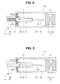
- the scanning endoscope 2 may be provided with a distal end portion 11B as shown in FIG. 4 , for example, instead of the distal end portion 11A as shown in FIG. 2 .
- FIG. 4 illustrates an example of the configuration of the distal end portion of the scanning endoscope according to the first embodiment, the example being different from the one in FIG. 2 . Note that, hereinafter, detailed description on the components having the same configurations as those of the distal end portion 11A is omitted for simplification, and components having configurations different from those of the distal end portion 11 A are mainly described.
- the distal end portion 11B is configured such that the part of the optical fiber 51, which is located in the light transmission portion 12B, is covered in a covering method different from the one used for the distal end portion 11A.
- the distal end portion 11B includes a vibration-absorbing member 47 configured to cover the circumference of the part of the optical fiber 51 which is located in the light transmission portion 12B, and a fiber outer cover 48 configured to cover the circumference of at least a part of the vibration-absorbing member 47.
- the part of the optical fiber 51 which is located in the light transmission portion 12B is doubly covered with the vibration-absorbing member 47 and the fiber outer cover 48.
- the circumference of the portion adjacent to the holding member 44 (or the ferrule proximal end portion 46 fitted into the hole portion of the holding member 44) is covered with the vibration-absorbing member 47.
- the scanning endoscope 2 including the distal end portion 11B is capable of preventing the part (not directly related to the scanning of the object) of the optical fiber 51, which is located in the light transmission portion 12B, from oscillating in accordance with the vibration of the actuator portion 15, since the vibration of the actuator portion 15 to be transmitted toward the ferrule proximal end portion 46 is absorbed by the vibration-absorbing member 47.
- the scanning endoscope 2 including the distal end portion 11B only the part (directly related to the scanning of the object) of the optical fiber 51, which is located in the light emission portion 12A, can be oscillated in accordance with the vibration of the actuator portion 15, which enables a stable scanning of the object to be performed.
- the distal end portion 11A and the distal end portion 11B may be configured to include a composite cable which integrates a plurality of signal lines 45 inserted through the insertion hole of the holding member 44 and the part of the optical fiber 51 (which is located in the light transmission portion 12B) covered with the vibration-absorbing member 47 and the fiber outer cover 48, for example.
- FIGS. 5 and 6 relate to the second embodiment of the present invention.
- FIG 5 illustrates one example of a configuration of a distal end portion of a scanning endoscope according to the second embodiment.
- An insertion portion 11 of a scanning endoscope 2 includes a distal end portion 11C as shown in FIG. 5 , instead of the distal end portion 11A (or distal end portion 11B).
- the distal end portion 11C has a configuration substantially the same as the configuration in which the vibration-absorbing member 47 is eliminated from the distal end portion 11 A (or distal end portion 11B) and an optical fiber 52 is provided instead of the optical fiber 51 of the distal end portion 11 A.
- the optical fiber 52 includes a core (not shown) as a propagation path of the illumination light supplied from the main body apparatus 3 and a clad (not shown) covering around the core.
- the optical fiber 52 is formed such that an outer diameter (clad diameter) of a part located in a light transmission portion 12B is larger than an outer diameter (clad diameter) of a part located in a light emission portion 12A.
- the optical fiber 52 is formed such that the outer diameter (clad diameter) of the portion adjacent to the holding member 44, the portion being included in the part located in the light transmission portion 12B, is larger than the outer diameter (clad diameter) of the part located in the light emission portion 12A.
- the part of the optical fiber 52 located in the light emission portion 12A is disposed in the state not covered with a fiber outer cover 48. Furthermore, in the light-emission-side end portion of the light-guiding portion for illumination 12, the other part of the optical fiber 52 located in the light transmission portion 12B is disposed in the state covered with the fiber outer cover 48.
- the part of the optical fiber 52 which has a relatively smaller outer diameter (clad diameter) is located in the light emission portion 12A, and the other part of the optical fiber 52, which has a relatively larger outer diameter (clad diameter), is located in the light transmission portion 12B.
- the ferrule proximal end portion 46 of the ferrule 41 is fitted in the hole portion of the holding member 44, and thereby the part of the optical fiber 52 which is located in the light emission portion 12A, the actuator portion 15 connected to the plurality of signal lines 45, and the ferrule 41 are held in a cantilevered manner in the internal space of the housing 43.
- Power source of each section of the scanning endoscope system 1 is turned on, and then the controller 25 controls the light source unit 21 to switch the light sources 31a, 31b, and 31c from off to on, based on the control program stored in the memory 24, and controls the driver unit 22 to cause the signal generator 33 to output a driving signal for oscillating the light-guiding portion for illumination 12 in a predetermined scanning pattern.
- the driver unit 22 supplies a driving signal to the actuator portion 15, and in response to the supplied driving signal, the actuator portion 15 vibrates, to cause the part of the optical fiber 52 which is located in the light emission portion 12A to oscillate in the predetermined scanning pattern, and then mixed light of R light, G light and B light is emitted from the light emission surface of the optical fiber 52 as illumination light.
- the outer diameter (clad diameter) of the part of the optical fiber 52 located in the light emission portion 12A is different from that of the other part of the optical fiber 52 located in the light transmission portion 12B. Therefore, according to the above-described configuration of the distal end portion 11C, the vibration of the actuator portion 15 to be transmitted toward the ferrule proximal end portion 46 is reflected on (XY plane corresponding to) the border surface of the parts of the optical fiber 52 between the light emission portion 12A and the light transmission portion 12B, thereby preventing the other part (not directly related to the scanning of the object) of the optical fiber 52, which is located in the light transmission portion 12B, from oscillating in accordance with the vibration of the actuator portion 15.
- the scanning endoscope 2 including the distal end portion 11C is capable of causing only the part (directly related to the scanning of the object) of the optical fiber 52, which is located in the light emission portion 12A, to oscillate in accordance with the vibration of the actuator portion 15, thereby enabling stable scanning of the object to be performed.
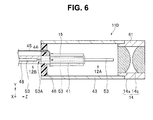
- the scanning endoscope 2 may be provided with a distal end portion 11D as shown in FIG. 6 , for example, instead of the distal end portion 11C as shown in FIG 5 .
- FIG. 6 illustrates an example of the configuration of the distal end portion of the scanning endoscope according to the second embodiment, the example being different from the one in FIG. 5 . Note that, hereinafter, detailed description on the components having the same configurations as those of the distal end portion 11C is omitted for simplification, and components having configurations different from those of the distal end portion 11C are mainly described.
- the distal end portion 11D has a configuration substantially the same as the configuration in which the vibration-absorbing member 47 is eliminated from the distal end portion 11A (or distal end portion 11B) and an optical fiber 53 is provided instead of the optical fiber 51 of the distal end portion 11 A.
- the optical fiber 53 includes a core (not shown) as a propagation path of the illumination light supplied from the main body apparatus 3 and a clad (not shown) covering around the core.
- the optical fiber 53 includes a reduced-diameter portion 53A in a predetermined range adjacent to the holding member 44 (or the ferrule proximal end portion 46 fitted into the hole portion of the holding member 44), the range being included in a part of the optical fiber 53 which is located in the light transmission portion 12B.
- the reduced-diameter portion 53A is formed so as to have an outer diameter (clad diameter) smaller than the outer diameter (clad diameter) of the part of the optical fiber 53 which is located in the light emission portion 12A.
- the outer diameter (clad diameter) of a portion other than the reduced-diameter portion 53A of the part of the optical fiber 53 which is located in the light transmission portion 12B is substantially equal to the outer diameter (clad diameter) of the part of the optical fiber 53 which is located in the light emission portion 12A.
- the part of the optical fiber 53 located in the light emission portion 12A is disposed in the state not covered with a fiber outer cover 48. Furthermore, in the light-emission-side end portion of the light-guiding portion for illumination 12, the part of the optical fiber 53 located in the light transmission portion 12B, which includes the diameter-reduced portion 53A, is disposed in the state covered with the fiber outer cover 48.
- the part of the optical fiber 53 which is formed so as to have a uniform outer diameter (clad diameter) is located in the light emission portion 12A, and the part of the optical fiber 53, which has a non-uniform outer diameter (clad diameter) at the diameter-reduced portion 53A, is located in the light transmission portion 12B.
- the ferrule proximal end portion 46 of the ferrule 41 is fitted in the hole portion of the holding member 44, and thereby the part of the optical fiber 53 which is located in the light emission portion 12A, the actuator portion 15 connected to the plurality of signal lines 45, and the ferrule 41 are held in a cantilevered manner in the internal space of the housing 43.
- the vibration of the actuator portion 15 to be transmitted toward the ferrule proximal end portion 46 is reflected on (XY plane corresponding to) the border surface of the parts of the optical fiber 53 between the light emission portion 12A and the light transmission portion 12B, thereby preventing the part (not directly related to the scanning of the object) of the optical fiber 53, which is located in the light transmission portion 12B, from oscillating in accordance with the vibration of the actuator portion 15.
- the scanning endoscope 2 including the distal end portion 11D, only the part (directly related to the scanning of the object) of the optical fiber 53, which is located in the light emission portion 12A, can be oscillated in accordance with the vibration of the actuator portion 15, which enables a stable scanning of the object to be performed.
Landscapes
- Health & Medical Sciences (AREA)
- Life Sciences & Earth Sciences (AREA)
- Surgery (AREA)
- Biomedical Technology (AREA)
- Medical Informatics (AREA)
- Optics & Photonics (AREA)
- Pathology (AREA)
- Radiology & Medical Imaging (AREA)
- Biophysics (AREA)
- Engineering & Computer Science (AREA)
- Physics & Mathematics (AREA)
- Heart & Thoracic Surgery (AREA)
- Nuclear Medicine, Radiotherapy & Molecular Imaging (AREA)
- Molecular Biology (AREA)
- Animal Behavior & Ethology (AREA)
- General Health & Medical Sciences (AREA)
- Public Health (AREA)
- Veterinary Medicine (AREA)
- Instruments For Viewing The Inside Of Hollow Bodies (AREA)
- Endoscopes (AREA)
Abstract
Description
- The present invention relates to a scanning endoscope, and more particularly to a scanning endoscope that acquires an image by scanning an object.
- Various kinds of techniques for reducing a diameter size of an insertion portion to be inserted into a body cavity of a subject to be examined are proposed for endoscopes in medical fields, in order to alleviate a burden on the subject to be examined. As an apparatus which belongs to such techniques, there has been conventionally known a scanning endoscope which does not include a solid-state image pickup device at a portion corresponding to the insertion portion as described above, for example.
- Specifically, the above-described scanning endoscope is configured, for example, to cause an actuator, which is mounted to the light-emission-side end portion of an illumination fiber that transmits illumination light emitted from a light source portion, to vibrate. This vibration causes the illumination fiber to oscillate in a predetermined scanning pattern, thereby enabling scanning of an object in a scanning range corresponding to the predetermined scanning pattern. Japanese Patent Application Laid-Open Publication No.
2009-212519 - However, the scanning endoscope having the configuration as described above has the following problem. That is, the vibration of the actuator or disturbance causes oscillation of a part of the illumination fiber, the part being located on a proximal end side of the illumination fiber with respect to the actuator mounting position (the part does not directly relate to the scanning of the object), and such oscillation problematically leads to unstable oscillation state of another part of the illumination fiber, the other part being located on a distal end side of the illumination fiber with respect to the actuator mounting position (the other part directly relates to the scanning of the object), for example.
- However, the Japanese Patent Application Laid-Open Publication No.
2009-212519 2009-212519 - The present invention has been achieved in view of the above-described circumstances, and an object of the present invention is to provide a scanning endoscope that is capable of performing scanning of an object in a more stable manner than that in conventional scanning endoscopes.
- A scanning endoscope according to one aspect of the present invention includes: a light-guiding portion configured to guide illumination light for illuminating an object through an optical fiber and emit the guided illumination light from a light emission surface positioned on a distal end side of the optical fiber; an actuator portion configured to vibrate in response to a supply of a driving signal for scanning the object in a predetermined scanning pattern, to thereby cause a part of the optical fiber to oscillate, the part of the optical fiber being located in a light emission portion which includes the light emission surface; a holding member configured to be able to hold the part of the optical fiber located in the light emission portion and the actuator portion, in a cantilevered manner; and a vibration-absorbing member provided at least on a circumference of a portion of the optical fiber adjacent to the holding member, the portion being included in another part of the optical fiber which is located in a light transmission portion which does not include the light emission surface.
- A scanning endoscope according to another one aspect of the present invention includes: a light-guiding portion configured to guide illumination light for illuminating an object through an optical fiber and emit the guided illumination light from a light emission surface positioned on a distal end side of the optical fiber; an actuator portion configured to vibrate in response to a supply of a driving signal for scanning the object in a predetermined scanning pattern, to thereby cause a part of the optical fiber to oscillate, the part of the optical fiber being located in a light emission portion which includes the light emission surface; and a holding member configured to be able to hold the part of the optical fiber located in the light emission portion and the actuator portion, in a cantilevered manner, wherein the optical fiber is formed such that at least an outer diameter of a portion of the optical fiber adjacent to the holding member, the portion being included in another part of the optical fiber located in a light transmission portion which does not include the light emission surface, and an outer diameter of the part of the optical fiber which is located in the light emission portion are different from each other.
-
-
FIG. 1 illustrates a configuration of a main part of a scanning endoscope system including a scanning endoscope according to an embodiment of the present invention. -
FIG. 2 illustrates one example of a configuration of a distal end portion of a scanning endoscope according to a first embodiment. -
FIG 3 is a cross-sectional view taken along III-III line inFIG 2 . -
FIG. 4 illustrates an example of the configuration of the distal end portion of the scanning endoscope according to the first embodiment, the example being different from the one inFIG. 2 . -
FIG. 5 illustrates one example of a configuration of a distal end portion of a scanning endoscope according to a second embodiment. -
FIG. 6 illustrates an example of the configuration of the distal end portion of the scanning endoscope according to the second embodiment, the example being different from the one inFIG 5 . - Hereinafter, embodiments of the present invention will be described with reference to drawings.
-
FIGS. 1 to 4 relate to the first embodiment of the present invention.FIG 1 illustrates a configuration of a main part of a scanning endoscope system including a scanning endoscope according to an embodiment of the present invention. - A
scanning endoscope system 1 includes, as shown inFIG. 1 for example, ascanning endoscope 2 configured to be insertable into a body cavity of a subject to be examined, amain body apparatus 3 connected to thescanning endoscope 2, and amonitor 4 connected to themain body apparatus 3. - The
scanning endoscope 2 includes aninsertion portion 11 formed in an elongated cylindrical shape and having flexibility. In addition, theinsertion portion 11 includes, at the proximal end portion thereof, a connector, for example, not shown, for detachably connecting thescanning endoscope 2 to themain body apparatus 3. -
FIG. 2 illustrates one example of a configuration of a distal end portion of the scanning endoscope according to the first embodiment. As shown inFIG. 2 , theinsertion portion 11 includes, at adistal end portion 11 A, a light-emission-side end portion of a light-guiding portion forillumination 12 configured to guide illumination light supplied from themain body apparatus 3 with anoptical fiber 51 to allow the illumination light to emit from a light emission surface positioned on the distal end side of theoptical fiber 51, a light condensingoptical system 14 configured to condense the illumination light emitted from the light-guiding portion forillumination 12, the light condensingoptical system 14 being arranged so as to be fixed by alens frame 61, and anactuator portion 15 provided at the light-emission-side end portion of the light-guiding portion forillumination 12 and configured to vibrate in response to a driving signal supplied through a plurality ofsignal lines 45 connected to themain body apparatus 3,to thereby enable a part of theoptical fiber 51 which is located in thelight emission portion 12A of the light-guiding portion forillumination 12 to oscillate. Note that, though not shown inFIG 2 , thedistal end portion 11A of theinsertion portion 11 includes a light-incident-side end portion of a light-guiding portion forlight reception 13 that receives return light from the object to guide the received return light to themain body apparatus 3. - The
optical fiber 51 is formed by including a core (not shown) which is a propagation path of the illumination light supplied from themain body apparatus 3 and a clad (not shown) covering around the core. - In the light-emission-side end portion of the light-guiding portion for
illumination 12, a part of theoptical fiber 51 located in thelight emission portion 12A including the light emission surface is disposed in the state not covered with a vibration-absorbingmember 47 and a fiberouter cover 48. Furthermore, in the light-emission-side end portion of the light-guiding portion forillumination 12, another part of theoptical fiber 51 located in thelight transmission portion 12B which does not include the light emission surface is disposed in the state covered with the vibration-absorbingmember 47 and the fiberouter cover 48. - Each of the
lenses optical system 14 are configured to have a positive refractive power. - As shown in
FIG. 2 , the part of theoptical fiber 51 which is located in thelight emission portion 12A is arranged so as to penetrate through thedistal end portion 11A of theinsertion portion 11, and thedistal end portion 11A of theinsertion portion 11 is provided with: aferrule 41 including on the outer surface thereof theactuator portion 15; ahousing 43 made of a hollow cylindrical-shaped metal or the like; aholding member 44 which holds theactuator portion 15 and theferrule 41 in thehousing 43; the plurality ofsignal lines 45; the vibration-absorbingmember 47; and the fiberouter cover 48. -
FIG. 3 is a cross-sectional view taken along the III-III line inFIG. 2 . As shown inFIG. 3 , theferrule 41 as a joint member is arranged between theoptical fiber 51 and theactuator portion 15. Specifically, theferrule 41 is made of zirconia (ceramic) or nickel, etc., for example. - As shown in
FIG 3 , theferrule 41 is formed as a quadrangular prism and includesside surfaces side surfaces ferrule 41, the part of theoptical fiber 51 which is located on the proximal end side of thelight emission portion 12A is fixedly arranged. Note that theferrule 41 may be formed in another shape other than quadrangular prism, as long as the ferrule has a rectangular prism shape. - As shown in
FIG 3 , theactuator portion 15 includes anactuator 15a arranged along theside surface 42a, anactuator 15b arranged along theside surface 42b, anactuator 15c arranged along theside surface 42c, and anactuator 15d arranged along theside surface 42d. - The
actuators amplifier 35 through a D/A converter 34a of adriver unit 22. - The
actuators amplifier 35 through the D/A converter 34b of thedriver unit 22. - As shown in
FIG 2 , thehousing 43 is formed so as to have an inner diameter enough to cover around the light-emission-side end portion of the light-guiding portion forillumination 12, theactuator portion 15 and theferrule 41. In addition, as shown inFIG 2 , the distal end side of thehousing 43 is coupled to a predetermined position on the proximal end side of thelens frame 61. - As shown in
FIG 2 , theholding member 44 is formed such that a plane (hereinafter, also referred to as the XY plane), which is perpendicular to a longitudinal direction (hereinafter, also referred to as the Z-axis direction) of the light-guiding portion forillumination 12, has substantially a ring shape, for example. In addition, theholding member 44 is mounted in the state where the surface (side surface) parallel to the Z-axis direction is brought into contact with the inner circumferential surface of thehousing 43. Further, theholding member 44 includes a hole portion into which a ferruleproximal end portion 46, which is located at a position away from the arranging position of theactuator portion 15 toward the proximal end side, can be fitted. Furthermore, theholding member 44 includes an insertion hole through which the plurality ofsignal lines 45 can be inserted. That is, with the configuration of theholding member 44 as described above, the ferruleproximal end portion 46 of theferrule 41 is fitted in the hole portion of theholding member 44, and thereby the part of theoptical fiber 51 which is located in thelight emission portion 12A, theactuator portion 15 connected to the plurality ofsignal lines 45, and theferrule 41 are held in a cantilevered manner in the internal space of thehousing 43. - The vibration-absorbing
member 47 is, for example, made of an adhesive or a soft rubber and the like, and formed so as to cover a circumference of a portion of the optical fiber adjacent to the holding member 44 (or the ferruleproximal end portion 46 fitted into the hole portion of the holding portion 44), the portion being included in the part of theoptical fiber 51 which is located in thelight transmission portion 12B. - The fiber
outer cover 48 is formed so as to cover a circumference of at least one portion located on the proximal end side with respect to the portion covered with the vibration-absorbingmember 47, the one portion being included in the part of theoptical fiber 51 which is located in thelight transmission portion 12B. - That is, with the configuration as described above, the part of the
optical fiber 51 from the light emission surface to the inside of theferrule 41 is located in thelight emission portion 12A, and the other part of theoptical fiber 51, which extends outward (toward the proximal end side) from the ferruleproximal end portion 46, is located in thelight transmission portion 12B. Note that, in the present embodiment, such a division between thelight emission portion 12A and thelight transmission portion 12B is applied not only to thedistal end portion 11A but also to adistal end portion 11B to be described later. - The
main body apparatus 3 includes alight source unit 21, thedriver unit 22, adetection unit 23, amemory 24, and acontroller 25. - The
light source unit 21 includes a function as a light source portion that supplies illumination light for illuminating an object. Specifically, as shown inFIG. 1 , thelight source unit 21 includes alight source 31a, alight source 31b, alight source 31c, and amultiplexer 32. - The
light source 31a includes a laser light source, etc., for example, and configured to emit light in the red wavelength band (hereinafter, also referred to as R light) to themultiplexer 32, when turned on under the control by thecontroller 25. - The
light source 31b includes a laser light source, etc., for example, and configured to emit light in the green wavelength band (hereinafter, also referred to as G light) to themultiplexer 32, when turned on under the control by thecontroller 25. - The
light source 31c includes a laser light source, etc., for example, and configured to emit light in the blue wavelength band (hereinafter, also referred to as B light) to themultiplexer 32, when turned on under the control by thecontroller 25. - The
multiplexer 32 is configured to multiplex the R light emitted from thelight source 31a, the G light emitted from thelight source 31b, and the B light emitted from thelight source 31c and supply the multiplexed light onto the light incident surface of the light-guiding portion forillumination 12. - As shown in
FIG. 1 , thedriver unit 22 includes asignal generator 33, D/A converters amplifier 35. - The
signal generator 33 is configured to generate a driving signal for causing the light-guiding portion forillumination 12 to oscillate, and configured to output the driving signal to the D/A converters controller 25. - Each of the D/
A converters signal generator 33 into an analog driving signal to output the analog driving signal to theamplifier 35. - The
amplifier 35 is configured to amplify the driving signal outputted from each of the D/A converters actuator portion 15. - As shown in
FIG. 1 , thedetection unit 23 includes ademultiplexer 36,detectors D converters - The
demultiplexer 36 includes a dichroic mirror and the like and configured to separate the return light emitted from the light emission surface of the light-guiding portion forlight reception 13 into light of each color component of R (red), G (green), and B (blue), and emit the separated light to each of thedetectors - The
detector 37a is configured to detect the intensity of the R light outputted from thedemultiplexer 36, generate an analog R signal corresponding to the detected intensity of the R light, and output the generated analog R signal to the A/D converter 38a. - The
detector 37b is configured to detect the intensity of the G light outputted from thedemultiplexer 36, generate an analog G signal corresponding to the detected intensity of the G light, and output the generated analog G signal to the A/D converter 38b. - The
detector 37c is configured to detect the intensity of the B light outputted from thedemultiplexer 36, generate an analog B signal corresponding to the detected intensity of the B light, and output the generated analog B signal to the A/D converter 38c. - The A/
D converter 38a is configured to convert the analog R signal outputted from thedetector 37a into a digital R signal, to output the digital R signal to thecontroller 25. - The A/
D converter 38b is configured to convert the analog G signal outputted from thedetector 37b into a digital G signal, to output the digital G signal to thecontroller 25. - The A/
D converter 38c is configured to convert the analog B signal outputted from thedetector 37c into a digital B signal, to output the digital B signal to thecontroller 25. - A
memory 24 previously stores a control program for controlling themain body apparatus 3, etc. - The
controller 25 includes a CPU, etc., and is configured to read the control program stored in thememory 24 and control thelight source unit 21 and thedriver unit 22 based on the read control program. That is, theactuator portion 15 vibrates based on the driving signal supplied from thedriver unit 22 according to the above-described control by thecontroller 25, thereby capable of oscillating the part of theoptical fiber 51 which is located in thelight emission portion 12A of the light-guiding portion forillumination 12 such that the irradiation position of the illumination light with which the object is irradiated draws a trajectory corresponding to a predetermined scanning pattern (for example, spiral shape, Lissajous shape, or the like). - The
controller 25 is configured to generate an image based on the R signal, G signal, and B signal outputted from thedetection unit 23, to cause the generated image to be displayed on themonitor 4. - Next, description will be made on the working of the
scanning endoscope system 1 including thescanning endoscope 2 according to the present embodiment. - Power source of each section of the
scanning endoscope system 1 is turned on, and then thecontroller 25 controls thelight source unit 21 to switch thelight sources memory 24, and controls thedriver unit 22 to cause thesignal generator 33 to output a driving signal for oscillating the light-guiding portion forillumination 12 in a predetermined scanning pattern. According to such control by thecontroller 25, thedriver unit 22 supplies a driving signal to theactuator portion 15, and in response to the supplied driving signal, theactuator portion 15 vibrates, to cause the part of theoptical fiber 51 which is located in thelight emission portion 12A to oscillate in the predetermined scanning pattern, and then mixed light of R light, G light and B light is emitted from the light emission surface of theoptical fiber 51 as illumination light. - According to the above-described configuration of the
distal end portion 11A, in the part of theoptical fiber 51 which is located in thelight transmission portion 12B, the portion adjacent to the holding member 44 (or the ferruleproximal end portion 46 fitted into the hole portion of the holding member 44) is covered with the vibration-absorbingmember 47. Therefore, according to the above-described configuration of thedistal end portion 11A, the vibration of theactuator portion 15 to be transmitted toward the ferruleproximal end portion 46, is absorbed by the vibration-absorbingmember 47, which prevents the part (not directly related to the scanning of the object) of theoptical fiber 51 which is located in thelight transmission portion 12B from oscillating in accordance with the vibration of theactuator portion 15. As a result, with thescanning endoscope 2 including thedistal end portion 11A, only the part (directly related to the scanning of the object) of theoptical fiber 51 which is located in thelight emission portion 12A can be oscillated in accordance with the vibration of theactuator portion 15, which enables a stable scanning of the object to be performed. - Alternatively, in the present embodiment, the
scanning endoscope 2 may be provided with adistal end portion 11B as shown inFIG. 4 , for example, instead of thedistal end portion 11A as shown inFIG. 2 .FIG. 4 illustrates an example of the configuration of the distal end portion of the scanning endoscope according to the first embodiment, the example being different from the one inFIG. 2 . Note that, hereinafter, detailed description on the components having the same configurations as those of thedistal end portion 11A is omitted for simplification, and components having configurations different from those of thedistal end portion 11 A are mainly described. - As shown in
FIG. 4 , thedistal end portion 11B is configured such that the part of theoptical fiber 51, which is located in thelight transmission portion 12B, is covered in a covering method different from the one used for thedistal end portion 11A. - Specifically, the
distal end portion 11B includes a vibration-absorbingmember 47 configured to cover the circumference of the part of theoptical fiber 51 which is located in thelight transmission portion 12B, and a fiberouter cover 48 configured to cover the circumference of at least a part of the vibration-absorbingmember 47. In other words, in thedistal end portion 11B, the part of theoptical fiber 51 which is located in thelight transmission portion 12B is doubly covered with the vibration-absorbingmember 47 and the fiberouter cover 48. In addition, according to the above-described configuration of thedistal end portion 11B, in the part of theoptical fiber 51 which is located in thelight transmission portion 12B, the circumference of the portion adjacent to the holding member 44 (or the ferruleproximal end portion 46 fitted into the hole portion of the holding member 44) is covered with the vibration-absorbingmember 47. - Therefore, the
scanning endoscope 2 including thedistal end portion 11B is capable of preventing the part (not directly related to the scanning of the object) of theoptical fiber 51, which is located in thelight transmission portion 12B, from oscillating in accordance with the vibration of theactuator portion 15, since the vibration of theactuator portion 15 to be transmitted toward the ferruleproximal end portion 46 is absorbed by the vibration-absorbingmember 47. As a result, with thescanning endoscope 2 including thedistal end portion 11B, only the part (directly related to the scanning of the object) of theoptical fiber 51, which is located in thelight emission portion 12A, can be oscillated in accordance with the vibration of theactuator portion 15, which enables a stable scanning of the object to be performed. - Note that, according to the present embodiment, the
distal end portion 11A and thedistal end portion 11B may be configured to include a composite cable which integrates a plurality ofsignal lines 45 inserted through the insertion hole of the holdingmember 44 and the part of the optical fiber 51 (which is located in thelight transmission portion 12B) covered with the vibration-absorbingmember 47 and the fiberouter cover 48, for example. -
FIGS. 5 and6 relate to the second embodiment of the present invention.FIG 5 illustrates one example of a configuration of a distal end portion of a scanning endoscope according to the second embodiment. - Note that, in the present embodiment, detailed description on the components having the same configuration as those in the first embodiment is omitted, and components having configurations different from those in the first embodiment are mainly described.
- An
insertion portion 11 of ascanning endoscope 2 according to the present embodiment includes adistal end portion 11C as shown inFIG. 5 , instead of thedistal end portion 11A (ordistal end portion 11B). - As shown in
FIG. 5 , thedistal end portion 11C has a configuration substantially the same as the configuration in which the vibration-absorbingmember 47 is eliminated from thedistal end portion 11 A (ordistal end portion 11B) and anoptical fiber 52 is provided instead of theoptical fiber 51 of thedistal end portion 11 A. - The
optical fiber 52 includes a core (not shown) as a propagation path of the illumination light supplied from themain body apparatus 3 and a clad (not shown) covering around the core. In addition, theoptical fiber 52 is formed such that an outer diameter (clad diameter) of a part located in alight transmission portion 12B is larger than an outer diameter (clad diameter) of a part located in alight emission portion 12A. In other words, theoptical fiber 52 is formed such that the outer diameter (clad diameter) of the portion adjacent to the holdingmember 44, the portion being included in the part located in thelight transmission portion 12B, is larger than the outer diameter (clad diameter) of the part located in thelight emission portion 12A. - In the light-emission-side end portion of the light-guiding portion for
illumination 12, the part of theoptical fiber 52 located in thelight emission portion 12A is disposed in the state not covered with a fiberouter cover 48. Furthermore, in the light-emission-side end portion of the light-guiding portion forillumination 12, the other part of theoptical fiber 52 located in thelight transmission portion 12B is disposed in the state covered with the fiberouter cover 48. - That is, according to the configuration as described above, the part of the
optical fiber 52, which has a relatively smaller outer diameter (clad diameter), is located in thelight emission portion 12A, and the other part of theoptical fiber 52, which has a relatively larger outer diameter (clad diameter), is located in thelight transmission portion 12B. In addition, according to the configuration of the holdingmember 44 of thedistal end portion 11C, the ferruleproximal end portion 46 of theferrule 41 is fitted in the hole portion of the holdingmember 44, and thereby the part of theoptical fiber 52 which is located in thelight emission portion 12A, theactuator portion 15 connected to the plurality ofsignal lines 45, and theferrule 41 are held in a cantilevered manner in the internal space of thehousing 43. - Next, description will be made on the working of the
scanning endoscope system 1 including thescanning endoscope 2 according to the present embodiment. - Power source of each section of the
scanning endoscope system 1 is turned on, and then thecontroller 25 controls thelight source unit 21 to switch thelight sources memory 24, and controls thedriver unit 22 to cause thesignal generator 33 to output a driving signal for oscillating the light-guiding portion forillumination 12 in a predetermined scanning pattern. According to such control by thecontroller 25, thedriver unit 22 supplies a driving signal to theactuator portion 15, and in response to the supplied driving signal, theactuator portion 15 vibrates, to cause the part of theoptical fiber 52 which is located in thelight emission portion 12A to oscillate in the predetermined scanning pattern, and then mixed light of R light, G light and B light is emitted from the light emission surface of theoptical fiber 52 as illumination light. - According to the above-described configuration of the
distal end portion 11C, the outer diameter (clad diameter) of the part of theoptical fiber 52 located in thelight emission portion 12A is different from that of the other part of theoptical fiber 52 located in thelight transmission portion 12B. Therefore, according to the above-described configuration of thedistal end portion 11C, the vibration of theactuator portion 15 to be transmitted toward the ferruleproximal end portion 46 is reflected on (XY plane corresponding to) the border surface of the parts of theoptical fiber 52 between thelight emission portion 12A and thelight transmission portion 12B, thereby preventing the other part (not directly related to the scanning of the object) of theoptical fiber 52, which is located in thelight transmission portion 12B, from oscillating in accordance with the vibration of theactuator portion 15. As a result, thescanning endoscope 2 including thedistal end portion 11C is capable of causing only the part (directly related to the scanning of the object) of theoptical fiber 52, which is located in thelight emission portion 12A, to oscillate in accordance with the vibration of theactuator portion 15, thereby enabling stable scanning of the object to be performed. - In the present embodiment, the
scanning endoscope 2 may be provided with adistal end portion 11D as shown inFIG. 6 , for example, instead of thedistal end portion 11C as shown inFIG 5 .FIG. 6 illustrates an example of the configuration of the distal end portion of the scanning endoscope according to the second embodiment, the example being different from the one inFIG. 5 . Note that, hereinafter, detailed description on the components having the same configurations as those of thedistal end portion 11C is omitted for simplification, and components having configurations different from those of thedistal end portion 11C are mainly described. - As shown in
FIG 6 , thedistal end portion 11D has a configuration substantially the same as the configuration in which the vibration-absorbingmember 47 is eliminated from thedistal end portion 11A (ordistal end portion 11B) and anoptical fiber 53 is provided instead of theoptical fiber 51 of thedistal end portion 11 A. - The
optical fiber 53 includes a core (not shown) as a propagation path of the illumination light supplied from themain body apparatus 3 and a clad (not shown) covering around the core. In addition, theoptical fiber 53 includes a reduced-diameter portion 53A in a predetermined range adjacent to the holding member 44 (or the ferruleproximal end portion 46 fitted into the hole portion of the holding member 44), the range being included in a part of theoptical fiber 53 which is located in thelight transmission portion 12B. - The reduced-
diameter portion 53A is formed so as to have an outer diameter (clad diameter) smaller than the outer diameter (clad diameter) of the part of theoptical fiber 53 which is located in thelight emission portion 12A. Note that, in the present embodiment, the outer diameter (clad diameter) of a portion other than the reduced-diameter portion 53A of the part of theoptical fiber 53 which is located in thelight transmission portion 12B is substantially equal to the outer diameter (clad diameter) of the part of theoptical fiber 53 which is located in thelight emission portion 12A. - In the light-emission-side end portion of the light-guiding portion for
illumination 12, the part of theoptical fiber 53 located in thelight emission portion 12A is disposed in the state not covered with a fiberouter cover 48. Furthermore, in the light-emission-side end portion of the light-guiding portion forillumination 12, the part of theoptical fiber 53 located in thelight transmission portion 12B, which includes the diameter-reducedportion 53A, is disposed in the state covered with the fiberouter cover 48. - That is, with the configuration as described above, the part of the
optical fiber 53, which is formed so as to have a uniform outer diameter (clad diameter), is located in thelight emission portion 12A, and the part of theoptical fiber 53, which has a non-uniform outer diameter (clad diameter) at the diameter-reducedportion 53A, is located in thelight transmission portion 12B. In addition, according to the configuration of the holdingmember 44 of thedistal end portion 11D, the ferruleproximal end portion 46 of theferrule 41 is fitted in the hole portion of the holdingmember 44, and thereby the part of theoptical fiber 53 which is located in thelight emission portion 12A, theactuator portion 15 connected to the plurality ofsignal lines 45, and theferrule 41 are held in a cantilevered manner in the internal space of thehousing 43. - Therefore, according to the
scanning endoscope 2 including thedistal end portion 11D, the vibration of theactuator portion 15 to be transmitted toward the ferruleproximal end portion 46 is reflected on (XY plane corresponding to) the border surface of the parts of theoptical fiber 53 between thelight emission portion 12A and thelight transmission portion 12B, thereby preventing the part (not directly related to the scanning of the object) of theoptical fiber 53, which is located in thelight transmission portion 12B, from oscillating in accordance with the vibration of theactuator portion 15. As a result, with thescanning endoscope 2 including thedistal end portion 11D, only the part (directly related to the scanning of the object) of theoptical fiber 53, which is located in thelight emission portion 12A, can be oscillated in accordance with the vibration of theactuator portion 15, which enables a stable scanning of the object to be performed. - It is needless to say that the present invention is not limited to the above-described embodiments, and various changes and modifications are possible in a range without departing from the gist of the invention.
- This application claims the benefit of Japanese Application No.
2013-146851
Claims (9)
- A scanning endoscope comprising:a light-guiding portion configured to guide illumination light for illuminating an object through an optical fiber and emit the guided illumination light from a light emission surface positioned on a distal end side of the optical fiber;an actuator portion configured to vibrate in response to a supply of a driving signal for scanning the object in a predetermined scanning pattern, to thereby cause a part of the optical fiber to oscillate, the part of the optical fiber being located in a light emission portion which includes the light emission surface;a holding member configured to be able to hold the part of the optical fiber located in the light emission portion and the actuator portion, in a cantilevered manner; anda vibration-absorbing member provided at least on a circumference of a portion of the optical fiber adjacent to the holding member, the portion being included in another part of the optical fiber which is located in a light transmission portion which does not include the light emission surface.
- The scanning endoscope according to claim 1, wherein
the vibration-absorbing member is formed so as to cover the circumference of the portion of the optical fiber adjacent to the holding member, the portion being included in the other part of the optical fiber which is located in the light transmission portion, and
a circumference of at least one portion of the optical fiber located on a proximal end side with respect to the portion covered with the vibration-absorbing member is covered with an outer cover, the one portion being included in the other part of the optical fiber which is located in the light transmission portion. - The scanning endoscope according to claim 1, wherein the vibration-absorbing member is formed so as to cover the circumference of the other part of the optical fiber which is located in the light transmission portion, and
a circumference of at least a part of the vibration-absorbing member is covered with an outer cover. - The scanning endoscope according to claim 1, further comprising
a joint member in which the part of the optical fiber located in the light emission portion is disposed in a penetrated manner, the joint member having an outer surface on which the actuator portion is disposed, wherein
the holding member includes a hole portion in which a proximal end portion of the joint member can be fitted, the proximal end portion of the joint member being located away from a position where the actuator portion is disposed. - A scanning endoscope comprising:a light-guiding portion configured to guide illumination light for illuminating an object through an optical fiber and emit the guided illumination light from a light emission surface positioned on a distal end side of the optical fiber;an actuator portion configured to vibrate in response to a supply of a driving signal for scanning the object in a predetermined scanning pattern, to thereby cause a part of the optical fiber to oscillate, the part of the optical fiber being located in a light emission portion which includes the light emission surface; anda holding member configured to be able to hold the part of the optical fiber located in the light emission portion and the actuator portion, in a cantilevered manner,wherein the optical fiber is formed such that at least an outer diameter of a portion of the optical fiber adjacent to the holding member, the portion being included in another part of the optical fiber located in a light transmission portion which does not include the light emission surface, and an outer diameter of the part of the optical fiber which is located in the light emission portion are different from each other.
- The scanning endoscope according to claim 5, wherein the optical fiber is formed such that an outer diameter of the other part which is located in the light transmission portion is larger than an outer diameter of the part which is located in the light emission portion.
- The scanning endoscope according to claim 5, wherein the optical fiber is formed such that an outer diameter of a predetermined range is smaller than the outer diameter of the part which is located in the light emission portion, the predetermined range being included in the other part which is located in the light transmission portion and being adjacent to the holding member.
- The scanning endoscope according to claim 7, wherein a portion corresponding to the predetermined range of the optical fiber is covered with an outer cover.
- The scanning endoscope according to claim 5, further comprising a joint member in which the part of the optical fiber located in the light emission portion is disposed in a penetrated manner, the joint member having an outer surface on which the actuator portion is disposed,
wherein the holding member includes a hole portion in which a proximal end portion of the joint member can be fitted, the proximal end portion of the joint member being located away from a position where the actuator portion is disposed.
Applications Claiming Priority (2)
| Application Number | Priority Date | Filing Date | Title |
|---|---|---|---|
| JP2013146851 | 2013-07-12 | ||
| PCT/JP2014/059453 WO2015004961A1 (en) | 2013-07-12 | 2014-03-31 | Scanning endoscope |
Publications (1)
| Publication Number | Publication Date |
|---|---|
| EP2946717A1 true EP2946717A1 (en) | 2015-11-25 |
Family
ID=52279658
Family Applications (1)
| Application Number | Title | Priority Date | Filing Date |
|---|---|---|---|
| EP14823239.0A Withdrawn EP2946717A1 (en) | 2013-07-12 | 2014-03-31 | Scanning endoscope |
Country Status (5)
| Country | Link |
|---|---|
| US (1) | US9661998B2 (en) |
| EP (1) | EP2946717A1 (en) |
| JP (1) | JP5765756B2 (en) |
| CN (1) | CN105050474B (en) |
| WO (1) | WO2015004961A1 (en) |
Cited By (1)
| Publication number | Priority date | Publication date | Assignee | Title |
|---|---|---|---|---|
| US10568495B2 (en) | 2015-06-24 | 2020-02-25 | Olympus Corporation | Scanning endoscope system |
Families Citing this family (15)
| Publication number | Priority date | Publication date | Assignee | Title |
|---|---|---|---|---|
| JP6438221B2 (en) * | 2014-06-25 | 2018-12-12 | オリンパス株式会社 | Optical scanning actuator and optical scanning device |
| JP5959788B1 (en) * | 2014-11-20 | 2016-08-02 | オリンパス株式会社 | Scanning endoscope |
| BR112018008198A2 (en) * | 2015-10-27 | 2018-10-23 | Koninklijke Philips N.V. | probe device, catheter and system |
| JPWO2017098825A1 (en) * | 2015-12-09 | 2018-10-04 | オリンパス株式会社 | Optical scanning endoscope |
| WO2017149863A1 (en) * | 2016-02-29 | 2017-09-08 | オリンパス株式会社 | Scanning endoscope |
| WO2017169555A1 (en) * | 2016-03-30 | 2017-10-05 | オリンパス株式会社 | Scanning endoscope and method for adjusting irradiation position for scanning endoscope |
| US10959608B2 (en) * | 2016-03-31 | 2021-03-30 | Tohoku University | Optical imaging device |
| DE112016007142T5 (en) * | 2016-09-14 | 2019-04-25 | Olympus Corporation | Optical fiber scanner, lighting device and observation device |
| EP4166060A3 (en) * | 2016-12-22 | 2023-07-26 | Magic Leap, Inc. | Methods and systems for fabrication of shaped fiber elements for scanning fiber displays |
| WO2018161259A1 (en) * | 2017-03-07 | 2018-09-13 | Goertek Inc. | Laser projection device and laser projection system |
| CN110858029A (en) * | 2018-08-24 | 2020-03-03 | 成都理想境界科技有限公司 | A scanning driver and optical fiber scanner |
| WO2020044541A1 (en) * | 2018-08-31 | 2020-03-05 | オリンパス株式会社 | Optical fiber scanner, illumination device, and observation device |
| CN112433359A (en) * | 2019-08-26 | 2021-03-02 | 成都理想境界科技有限公司 | Optical fiber scanner, display module and projection display equipment |
| EP3964116A1 (en) | 2020-09-02 | 2022-03-09 | Ambu A/S | Endoscope tip part |
| EP4011270A1 (en) | 2020-12-08 | 2022-06-15 | Ambu A/S | Endoscope tip part with improved optical properties |
Family Cites Families (18)
| Publication number | Priority date | Publication date | Assignee | Title |
|---|---|---|---|---|
| JP3092542B2 (en) * | 1997-03-10 | 2000-09-25 | 株式会社村田製作所 | LC composite parts |
| JP2001174744A (en) * | 1999-10-06 | 2001-06-29 | Olympus Optical Co Ltd | Optical scanning probe device |
| US7338439B2 (en) * | 2003-09-05 | 2008-03-04 | Pentax Corporation | Condensing optical system, confocal optical system, and scanning confocal endoscope |
| DE102006046925A1 (en) | 2006-09-28 | 2008-04-03 | Jenlab Gmbh | Method for laser endoscopy e.g. for medical work and for semiconductor processing, requires laser pulse for producing multi-photon processes as target ionization |
| US8957484B2 (en) | 2008-02-29 | 2015-02-17 | University Of Washington | Piezoelectric substrate, fabrication and related methods |
| US8757812B2 (en) * | 2008-05-19 | 2014-06-24 | University of Washington UW TechTransfer—Invention Licensing | Scanning laser projection display devices and methods for projecting one or more images onto a surface with a light-scanning optical fiber |
| JP2010162090A (en) * | 2009-01-13 | 2010-07-29 | Hoya Corp | Optical scanning endoscope |
| JP2011045525A (en) * | 2009-08-27 | 2011-03-10 | Fujifilm Corp | Endoscope |
| JP2011139781A (en) * | 2010-01-07 | 2011-07-21 | Hoya Corp | Position sensor, position control system, and endoscope apparatus |
| JP5914355B2 (en) * | 2010-11-30 | 2016-05-11 | オリンパス株式会社 | Piezoelectric actuator |
| JP2012148062A (en) * | 2010-12-27 | 2012-08-09 | Hoya Corp | Fiber scanning endoscope |
| WO2012090642A1 (en) * | 2010-12-27 | 2012-07-05 | Hoya株式会社 | Fiber scanning endoscope |
| JP5911238B2 (en) * | 2011-09-02 | 2016-04-27 | オリンパス株式会社 | Optical scanning device and endoscope, microscope, and projector provided with the same |
| JP2013121455A (en) * | 2011-12-12 | 2013-06-20 | Hoya Corp | Scanning type endoscope system |
| JP5363688B1 (en) * | 2012-01-11 | 2013-12-11 | オリンパスメディカルシステムズ株式会社 | Light irradiation apparatus, scanning endoscope apparatus, method for manufacturing light irradiation apparatus, and method for manufacturing scanning endoscope |
| KR101333761B1 (en) * | 2012-05-17 | 2013-11-28 | 한국생산기술연구원 | OCT Probe using PZT |
| JP6120624B2 (en) * | 2013-03-18 | 2017-04-26 | オリンパス株式会社 | Optical fiber scanner, illumination device and observation device |
| JP6129050B2 (en) * | 2013-10-08 | 2017-05-17 | オリンパス株式会社 | Optical fiber scanner, illumination device and observation device |
-
2014
- 2014-03-31 WO PCT/JP2014/059453 patent/WO2015004961A1/en not_active Ceased
- 2014-03-31 JP JP2014557929A patent/JP5765756B2/en active Active
- 2014-03-31 EP EP14823239.0A patent/EP2946717A1/en not_active Withdrawn
- 2014-03-31 CN CN201480012771.0A patent/CN105050474B/en not_active Expired - Fee Related
-
2015
- 2015-09-10 US US14/850,384 patent/US9661998B2/en active Active
Non-Patent Citations (1)
| Title |
|---|
| See references of WO2015004961A1 * |
Cited By (1)
| Publication number | Priority date | Publication date | Assignee | Title |
|---|---|---|---|---|
| US10568495B2 (en) | 2015-06-24 | 2020-02-25 | Olympus Corporation | Scanning endoscope system |
Also Published As
| Publication number | Publication date |
|---|---|
| CN105050474B (en) | 2017-12-01 |
| JPWO2015004961A1 (en) | 2017-03-02 |
| US9661998B2 (en) | 2017-05-30 |
| US20150374219A1 (en) | 2015-12-31 |
| JP5765756B2 (en) | 2015-08-19 |
| WO2015004961A1 (en) | 2015-01-15 |
| CN105050474A (en) | 2015-11-11 |
Similar Documents
| Publication | Publication Date | Title |
|---|---|---|
| EP2946717A1 (en) | Scanning endoscope | |
| JP5945640B2 (en) | Optical scanning device and scanning endoscope | |
| US9179830B2 (en) | Scanning endoscope apparatus | |
| EP2789289B1 (en) | Endoscope device and treatment device | |
| US20160081535A1 (en) | Scanning endoscope | |
| JP5993531B1 (en) | Scanning endoscope | |
| EP2976986A1 (en) | Endoscope system | |
| US9877640B2 (en) | Scanning endoscope having propagation portion with light absorbing portion or light reflecting portion on distal end face thereof | |
| US20170065156A1 (en) | Scanning-type endoscope | |
| JP5830453B2 (en) | Scanning endoscope | |
| WO2016143160A1 (en) | Scanning endoscope system | |
| JP6081678B1 (en) | Scanning endoscope | |
| JPWO2017149863A1 (en) | Scanning endoscope | |
| WO2016017199A1 (en) | Optical scanning observation system | |
| EP2910175A1 (en) | Scanning endoscope system | |
| JP2015089440A (en) | Scanning endoscope system | |
| JP2017077284A (en) | Scanning endoscope |
Legal Events
| Date | Code | Title | Description |
|---|---|---|---|
| PUAI | Public reference made under article 153(3) epc to a published international application that has entered the european phase |
Free format text: ORIGINAL CODE: 0009012 |
|
| 17P | Request for examination filed |
Effective date: 20150821 |
|
| AK | Designated contracting states |
Kind code of ref document: A1 Designated state(s): AL AT BE BG CH CY CZ DE DK EE ES FI FR GB GR HR HU IE IS IT LI LT LU LV MC MK MT NL NO PL PT RO RS SE SI SK SM TR |
|
| AX | Request for extension of the european patent |
Extension state: BA ME |
|
| RAP1 | Party data changed (applicant data changed or rights of an application transferred) |
Owner name: OLYMPUS CORPORATION |
|
| RAP1 | Party data changed (applicant data changed or rights of an application transferred) |
Owner name: OLYMPUS CORPORATION |
|
| DAX | Request for extension of the european patent (deleted) | ||
| RIN1 | Information on inventor provided before grant (corrected) |
Inventor name: YOSHINO, MASAHIRO |
|
| STAA | Information on the status of an ep patent application or granted ep patent |
Free format text: STATUS: THE APPLICATION HAS BEEN WITHDRAWN |
|
| 18W | Application withdrawn |
Effective date: 20161124 |