EP2946436B1 - A portable antenna - Google Patents
A portable antenna Download PDFInfo
- Publication number
- EP2946436B1 EP2946436B1 EP13820740.2A EP13820740A EP2946436B1 EP 2946436 B1 EP2946436 B1 EP 2946436B1 EP 13820740 A EP13820740 A EP 13820740A EP 2946436 B1 EP2946436 B1 EP 2946436B1
- Authority
- EP
- European Patent Office
- Prior art keywords
- antenna
- housing
- cord
- antenna assembly
- man
- Prior art date
- Legal status (The legal status is an assumption and is not a legal conclusion. Google has not performed a legal analysis and makes no representation as to the accuracy of the status listed.)
- Active
Links
Images















Classifications
-
- H—ELECTRICITY
- H01—ELECTRIC ELEMENTS
- H01Q—ANTENNAS, i.e. RADIO AERIALS
- H01Q1/00—Details of, or arrangements associated with, antennas
- H01Q1/08—Means for collapsing antennas or parts thereof
-
- H—ELECTRICITY
- H01—ELECTRIC ELEMENTS
- H01Q—ANTENNAS, i.e. RADIO AERIALS
- H01Q1/00—Details of, or arrangements associated with, antennas
- H01Q1/08—Means for collapsing antennas or parts thereof
- H01Q1/084—Pivotable antennas
-
- H—ELECTRICITY
- H01—ELECTRIC ELEMENTS
- H01Q—ANTENNAS, i.e. RADIO AERIALS
- H01Q1/00—Details of, or arrangements associated with, antennas
- H01Q1/08—Means for collapsing antennas or parts thereof
- H01Q1/088—Quick-releasable antenna elements
-
- H—ELECTRICITY
- H01—ELECTRIC ELEMENTS
- H01Q—ANTENNAS, i.e. RADIO AERIALS
- H01Q1/00—Details of, or arrangements associated with, antennas
- H01Q1/12—Supports; Mounting means
- H01Q1/1235—Collapsible supports; Means for erecting a rigid antenna
-
- H—ELECTRICITY
- H01—ELECTRIC ELEMENTS
- H01Q—ANTENNAS, i.e. RADIO AERIALS
- H01Q1/00—Details of, or arrangements associated with, antennas
- H01Q1/27—Adaptation for use in or on movable bodies
- H01Q1/273—Adaptation for carrying or wearing by persons or animals
-
- H—ELECTRICITY
- H01—ELECTRIC ELEMENTS
- H01Q—ANTENNAS, i.e. RADIO AERIALS
- H01Q1/00—Details of, or arrangements associated with, antennas
- H01Q1/48—Earthing means; Earth screens; Counterpoises
-
- H—ELECTRICITY
- H01—ELECTRIC ELEMENTS
- H01Q—ANTENNAS, i.e. RADIO AERIALS
- H01Q19/00—Combinations of primary active antenna elements and units with secondary devices, e.g. with quasi-optical devices, for giving the antenna a desired directional characteristic
- H01Q19/28—Combinations of primary active antenna elements and units with secondary devices, e.g. with quasi-optical devices, for giving the antenna a desired directional characteristic using a secondary device in the form of two or more substantially straight conductive elements
- H01Q19/30—Combinations of primary active antenna elements and units with secondary devices, e.g. with quasi-optical devices, for giving the antenna a desired directional characteristic using a secondary device in the form of two or more substantially straight conductive elements the primary active element being centre-fed and substantially straight, e.g. Yagi antenna
-
- H—ELECTRICITY
- H01—ELECTRIC ELEMENTS
- H01Q—ANTENNAS, i.e. RADIO AERIALS
- H01Q21/00—Antenna arrays or systems
- H01Q21/24—Combinations of antenna units polarised in different directions for transmitting or receiving circularly and elliptically polarised waves or waves linearly polarised in any direction
-
- H—ELECTRICITY
- H01—ELECTRIC ELEMENTS
- H01Q—ANTENNAS, i.e. RADIO AERIALS
- H01Q21/00—Antenna arrays or systems
- H01Q21/24—Combinations of antenna units polarised in different directions for transmitting or receiving circularly and elliptically polarised waves or waves linearly polarised in any direction
- H01Q21/26—Turnstile or like antennas comprising arrangements of three or more elongated elements disposed radially and symmetrically in a horizontal plane about a common centre
-
- H—ELECTRICITY
- H01—ELECTRIC ELEMENTS
- H01Q—ANTENNAS, i.e. RADIO AERIALS
- H01Q9/00—Electrically-short antennas having dimensions not more than twice the operating wavelength and consisting of conductive active radiating elements
- H01Q9/04—Resonant antennas
- H01Q9/16—Resonant antennas with feed intermediate between the extremities of the antenna, e.g. centre-fed dipole
-
- H—ELECTRICITY
- H01—ELECTRIC ELEMENTS
- H01Q—ANTENNAS, i.e. RADIO AERIALS
- H01Q1/00—Details of, or arrangements associated with, antennas
- H01Q1/06—Means for the lighting or illuminating of antennas, e.g. for purpose of warning
-
- H—ELECTRICITY
- H01—ELECTRIC ELEMENTS
- H01Q—ANTENNAS, i.e. RADIO AERIALS
- H01Q1/00—Details of, or arrangements associated with, antennas
- H01Q1/12—Supports; Mounting means
- H01Q1/22—Supports; Mounting means by structural association with other equipment or articles
- H01Q1/24—Supports; Mounting means by structural association with other equipment or articles with receiving set
- H01Q1/241—Supports; Mounting means by structural association with other equipment or articles with receiving set used in mobile communications, e.g. GSM
- H01Q1/242—Supports; Mounting means by structural association with other equipment or articles with receiving set used in mobile communications, e.g. GSM specially adapted for hand-held use
- H01Q1/243—Supports; Mounting means by structural association with other equipment or articles with receiving set used in mobile communications, e.g. GSM specially adapted for hand-held use with built-in antennas
-
- H—ELECTRICITY
- H01—ELECTRIC ELEMENTS
- H01Q—ANTENNAS, i.e. RADIO AERIALS
- H01Q7/00—Loop antennas with a substantially uniform current distribution around the loop and having a directional radiation pattern in a plane perpendicular to the plane of the loop
Definitions
- the present invention relates to a portable antenna and in particular but not limited to a satellite communications antenna designed to be operated whilst carried by a user.
- one soldier of a unit on field patrol carries a radio which operates in conjunction with an antenna to provide satellite communication between the unit and a base.
- Pistol grip antenna are not well suited for combat use as it is preferred that both hands of the solider are free to operate a weapon.
- US2012280869 relates to an antenna system in which the antenna is mounted to a bendable rod of sufficient rigidity to support the weight of the antenna when the rod is in a vertical orientation.
- a man-portable antenna assembly according to claim 1.
- the invention allows a solider to quickly erect or stow the antenna as necessary.
- the end of the pull-cord can for example be placed in easy reaching distance of one or both of the soldier's hands.
- the driven element which when the antenna is erect, extends laterally away from the support, is foldably mounted to the support so that it can fold inwardly towards the support when the antenna is stowed. This enables the antenna to be made more wieldy and less likely to snag on passing objects when stowed.
- the antenna comprises a ground plane which acts as a reflector for the driven element. It is preferred that the ground plane comprises radially extending members which are foldably mounted to the support so that they can fold inwardly towards the support when the antenna is being stowed.
- the mechanism comprises means to allow the antenna to be configurable by the solider with one hand. This leaves the soldier's other hand free to operate a weapon.
- the driven element is a dipole comprising two elongate members that extend radially away from the support in substantially opposite directions.
- the antenna may have two dipoles that are orientated perpendicular to one another.
- the mechanism comprises a further linkage between the driven element and the ground plane that is arranged to cause them to close and/or open together.
- each ground plane member may work independently of the others so that if one further linkage breaks or jams the other can still operate.
- the antenna assembly comprises a housing within which the antenna is housed when stowed. It is particularly favourable that the housing acts as a mast for the antenna when in an operational state. This allows the antenna to be held in a higher position when in use to improve transmission/reception, but also provides the benefit that the antenna can be lowered when not in use making it less conspicuous and wieldier.
- the antenna comprises an engaging surface that engages with the housing when the mechanical linkage is operated to cause the driven member and ground plane member to fold inwards towards the support.
- the mechanical linkage comprises means to retract the pull-cord after it has been pulled to operate the linkage.
- the means to retract the pull-cord includes a sprung spool from which the pull-cord is wound or unwound. This reduces the chance of the cord becoming snagged. It also means that the end of the pull cord can return to the same place so that the soldier can instinctively reach for it.
- the use of the term 'cord' within this specification is used to include other flexible elongate members such as, but not limited to, string, rope, cable, chain, strap or webbing, which can be wound around a spool.
- the mechanical linkage comprises a first pull-cord to erect the antenna and a second pull-cord to collapse the antenna.
- the first and second pull cords may be provided by separate portions of the same cord.
- the assembly comprises means to retract either pull-cord after it has been pulled. This may comprise two sprung spools associated with the first and second pull-cords, said spools arranged to rotate in opposite directions in order to release or wind the first and second pull-cords, and a biasing means connected between the two spools to provide a return tension to either spool in order to retract either the first or second pull-cords if extended.
- a further preferable feature is that the mechanical linkage includes a first engaging member fixed relative to the cord and a second engaging member fixed relative to the antenna.
- the first and second engaging members are arranged to engage when the pull cord is pulled in order to draw the antenna in and/or out of the housing. This allows the cord to rewind back onto the spool without affecting the configuration of the antenna.
- the mechanism comprises two pull-cords, it is preferred that each has an associated first and second engaging member in order that both can rewind.
- the mechanical linkage may comprises a linking member that extends through a slot in the housing, the linking member being fixed relative to a pull-cord(s) outside of the housing, and fixed relative to the antenna inside the housing.
- the figures 1-17 illustrate a portable antenna assembly 1 arranged for use with a radio (not shown) to allow satellite communication, e.g. through TACSAT and/or MUOS, to a command station.
- a radio not shown
- the antenna assembly 1 is designed to be carried on a soldier's S back, preferably mounted in or on a rucksack 100.
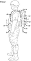
- Figs 1 and 2 illustrate an example in which the antenna assembly 1 is mounted against the side of the rucksack 100 using straps 101 with hook and loop fasteners.
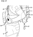
- the soldier S can cause an antenna 1A to collapse into housing shown in Fig 2 by pulling on handle 57 see Fig 16 , and conversely can erect the stowed antenna 1A by pulling on handle 39, see Fig 17 .
- the antenna assembly 1 comprises an antenna 1A having driven elements 2 (two dipoles arranged perpendicular to one another) and a ground plane 3 that acts as a reflector for the dipoles. Both the driven elements 2 and ground plane 3 are mounted to a central supporting column 4.
- the antenna assembly 1 further comprises a housing into which the antenna 1A can be stowed when not in use.
- the housing comprises an inner housing 5 (shown most clearly in Fig 9 ) which holds the antenna 1A when stowed.
- a casing (preferably sealed) 6 mounted to the inner housing 5 holds circuitry for driving the antenna 1A.
- the inner housing 5 and casing 6 are housed within an outer housing 7.
- a spacing 8, shown in Figs 11 & 12 between the outer housing 7 and inner housing 5 carries coaxial cabling between the antenna 1A and the circuitry within casing 6.
- the space 8 also houses pull-cords 40, 50 forming part of the operational mechanism to be described later.
- the outer housing 7, which is removable, is secured to an upper end cap 9 of the inner housing 5, by thumb screws 11 which locate into threaded apertures 12 defined by the end cap 9.
- the two driven elements are comprised from four elongate members 2 that, when in an operating arrangement, extend radially away from the supporting column 4. Each is spaced circumferentially from the next by around 90 degrees.
- the ground plane is similarly comprised from four elongate members 3 that extend radially away from the supporting column 4 when in an operating arrangement.
- the driven elements 2 and ground plane members 3 When erect, the driven elements 2 and ground plane members 3 are separated by a distance of substantially a quarter of a wavelength of the intended transmission wavelength as is well known in the art.
- the ground plane members 3 extend radially further outwards as compared to the driven members 2 so as to improve the transmission properties of the antenna 1A.
- the elongate members forming the driven elements 2 and ground plane 3 are comprised from sprung steel (or other conductive material) covered with a synthetic plastics material. In some embodiments the protective casing may be omitted.
- the elongate members may be releasably attached to the support. This may be achieved in a number of ways, examples including via a plug-in action similar to that used with an audio jack, or through a screw fitting. This allows any elongate member to be easily replaced should it break.
- the antenna assembly is orientated such that when the antenna 1A is deployed, two of the ground plane members 3 extend across, and may rest upon the shoulder's of the soldier S.
- the driven members 2 are preferably held above the soldier's S head.
- each ground plane member 3 and driven member 2 is counter levered about a knuckle; the ground plane members 3 to knuckles 13 and antenna members 2 to knuckles 14.
- Each knuckle 13, 14 is hinged about a mounting hinge 15 to either an upper mounting 4A or lower mounting 4B of the supporting column 4 which allows the each knuckle 13, 14 to rotate relative to the supporting column 4 about an axis substantially perpendicular to the main axis of the supporting column 4.
- each ground plane member 3 is hingedly connected at 16 through a link bar 17 to the knuckle 14 of the driven member 2 supported above it.
- each link bar 17 is connected by hinge 16A to the ground plane knuckle 13 at a point radially inward of the mounting hinge 15.
- the knuckle 14 of the driven member 2 is connected by hinge 16B to the link bar 17 at a point radically outward of the mounting hinge 15.
- a torsion spring 18 sits over a mounting hinge 15 between each knuckle 13, 14 and the mounting 4A, 4B to the central supporting column 4.
- the torsion springs 18 act to bias the knuckles 13, 14 outwardly from the central supporting column 4 into the radial configuration shown in Figs 5 and 7 .
- a radially outward portion 13A of each ground plane knuckle 13 extends beyond the outer perimeter of the lower mounting 4B.
- the driven members 2 and ground plane members 3 can fold inwardly towards the central support 4 without obstructing each other, they are arranged to be slightly offset from a vertical alignment as seen in Fig 10 . This is achieved, as shown in Figs 5 and 6 , by mounting the driven members 2 on one side of the hinge 16B, and the ground plane members 3 to the knuckles 13 on the other side of the hinge 16B.
- the lower mounting 4B defines slots 4C through which the coaxial cables (not shown) pass in order to run up through the central support 4 to the driven members 2.
- each locking pin 19 is mounted to lower mounting 4B.
- Each locking pin 19 defines a vertical through hole 19A. As illustrated in Figs 9 and 10 , when the antenna is assembled with the inner housing 5, each locking pin 19 extends through a longitudinal slot 5A in the housing 5.
- end cap 9 of the inner housing 5 has an inwardly sloping inner wall 9A.
- the wall defines four slots 9B through with ground plane members 3 extend when in an operational configuration.
- the wall 9A optionally defines a series of smaller slots 9C to reduce the build up of dirt and sand.
- Associated with each slot 9B is a recess 9D in the inner wall of the end cap 9B. Extending from either side into each recess 9D are camming surfaces 9E.
- the end cap 9 also comprises two apertures 9F through which two ends of a pull-cord 40 pass out of the antenna assembly 1.
- the knuckles 13 are housed in corresponding recesses 9D of the end cap 9 with outer portions 13A resting against the camming surfaces 9E, and the ground plane members 3 extending radially away from the central support 4 through slots 9B.
- a downward force is applied to central support 4.
- the reactionary force of the camming surfaces 9E against the outer portion 13A of knuckles 13, causes the knuckles 13 to rotate up about mounting hinges 15 (against the action of spring 18) which leads to the driven members 3 moving towards a vertical orientation alongside the central support 4.
- the rotation of knuckles 13 draws the link bar 17 in a downward direction which in turn causes knuckles 14 to rotate about mounting pivots 15 so that driven members 2 are rotated downwards towards a vertical orientation as illustrated in Fig 6 .
- the inwardly sloping inner wall 9A acts to guide driven members 2 inwardly towards the central support 4 in the instance that they have not folded inwardly enough to avoid contact with upper cap 9.
- the antenna assembly 1 is provided with a pull cord mechanism described below.
- a bottom cap 10 to which the sealed enclosure 6 is mounted by downwardly extending mounting spigots 20. Also extending between the bottom cap 10 and enclosure 6 are mounting spigots 21 for supporting pulleys 34, 35, 51, 52. Some of these spigot 21 incorporate mounting brackets 22 for pulley wheels 35, 52 arranged to rotate about an axis running normal to the spigot 21. Also provided are guide spigots which act as cord guides 24, and a central spigot 25 shown in Fig 12 .
- spool assembly 30 Seated between the end cap 10 and PCB enclosure 6 is spool assembly 30.
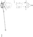
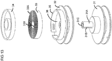
- the spool assembly 30, as illustrated in Figs 13 - 15 comprises two co-axial spools 31, 32, a spiral spring 33 and a retainer 34.
- the assembly is arranged to allow the spools 31, 32 to rotate relative to the end cap 10 and PCB housing 6, and each other.
- first spool 31 is mounted over spigot 6A which extends upwardly from the PCB housing 6 in vertical alignment to central spigot 25.
- Spool 31 itself comprises a spigot 31A onto which second spool 32 sits and can rotate relative to the first spool 31 or vice versa.
- a circumferential flange 35 of second spool 32 extending from a face opposing the first spool 31 provides a housing 36 for spring 33.
- the spring 33 is retained within the housing by retainer 34.
- the outer end 33A of the spiral spring 33 is secured to flange 35.
- the inner end 33B of spiral 33 is secured, by way of slot 31B to spigot 31A of the first spool 31 which, extends through second spool 32 and into housing 36. With this arrangement, rotation of either the first or the second spool relative to the other, will cause the spring 33 to be tightened or unwound.
- spool assembly 30 is retained by the central spigot 25 which engages in a vertical opening 31C in spigot 31A.
- first cord 40 used to deploy the antenna 1A.
- the cord 40 is held on spool 31 so that both ends of the cord 40 are wound around the spool 31 in the same direction (hand).
- a first pulley 34 takes a first end 40A of the cord 40 off the spool 31, a second pulley 35 rotates the cord 40A by ninety degrees, the cord 40A runs upwards parallel with the inner housing 5, through a bead 36, through an aperture 19A of a locking pin 19, and up to third pulley 37 mounted to a top end cap 9 which turns the cord 40A by ninety degrees.
- the cord 40A passes out of aperture 9F in the upper cap end 9 via a guide tube 38A secured to the upper cap end 9.
- the guide tube 38A reduces wear and the chance of the cord snagging against the end cap 9.
- a substantially identical arrangement (not shown) of pulleys on the other side of the inner casing 5 takes the second portion 40B of the cord 40 off the spool 31 and rotates the cord 40B by ninety degrees.
- the cord 40B runs upwards, parallel with the inner housing 5, through an aperture 19A of an opposing a locking pin 19 and up to a pulley 37B mounted to a top end cap 9 which turns the cord 40 by ninety degrees.
- the cord 40 then passes out of aperture 9F in the upper cap end 9, via a guide tube 37B where it is brought together with the first end 40A with a toggle 42.
- Both first 40A and second 40B portions of cord 40 are attached to a fabric looped handle 39 to ease grabbing and pulling of the cord 40.
- the cord 40 is guided through loops 42 on one of the shoulder straps of the rucksack 100 in order that the handle 39 hangs next to the soldier's S shoulder/chest where it is in easy reach.
- a pulling force on handle 39 causes both portions 40A, 40B of cord 40 to be unwound from the spool 31.
- Beads 36A, 36B which are fixed to their respective cord portions 40A, 40B are drawn upwardly to engage with the respective locking pins 19, whereupon further upward motion urges the locking pins 19 upwards along longitudinal slots 5A, and the central support 4 to which the locking pins are mounted, upwards through end cap 9.
- spring 18 causes the ground plane members 3 and driven members 2 to open out as described above. Excess upward motion of the antenna 1A is checked by engagement of locking pins 19 against stoppers 41.
- spring 33 recoils, causing the first spool 31 to rotate to redraw the cord 40. This can be achieved without causing the antenna 1A to withdraw into housing 5 as cord portions 40A, 40B are free to pass through aperture 19A of the locking pins. The cord 40 is redrawn until bead 36 engages against lower end cap 10.
- the second spool 32 Onto the second spool 32 is wound a second cord 50 used to collapse and stow the antenna 1A into housing 5.
- the cord 50 is held on spool 32 with both ends of the cord 50 wound around the spool 32 in the same direction (hand).
- Cords 40 and 50 are wound in opposite directions on their respective spools 31, 32.
- a forth pulley 51 takes a first end 50A of second cord 50 off the spool 32, a fifth pulley 52 rotates the cord 50 by about ninety degrees so that it runs upwards towards the upper end cap 9.
- a sixth pulley 53 mounted to the upper end cap 9 turns the cord 50A through one-hundred-and-eighty degrees.
- Cord 50 runs back down towards the lower end cap 10 passing though aperture 19A of locking pin 19.
- a bead 54 is mounted to cord 50 at a point above the locking pin 19.
- the cord 50 passes through stop 55 through spigot 24, and passes into guide tube 26 which runs through the PCB housing.
- the cord 50 passes out through the bottom of the PCB housing 6.
- a similar arrangement of pulleys guides the second portion 50B of the second cord 50 in a likewise fashion on the otherwise of the inner housing 5.
- the first and second portions of the second cord 50 are brought together by toggle 56. Both ends of the first and second portions of second cord 50 are attached to a fabric looped handle 57 to ease grabbing and pulling of the cord 50.
- handle 57 is arranged to hang below the antenna assembly 1 in easy reach of one of the soldier's hands.
- a pulling action on handle 57 causes the first and second portions 50A, 50B of cord 50 to be unwound from spool 32.
- Beads 54 secured to the respective first and second portions are drawn downwards into engagement with locking pins 19, whereupon further downward motion of the beads 54 urges the locking pins 19 to move downwardly along slots 5A. This provides the aforementioned downward force which causes the knuckles 13 to rotate and the antenna 1A to withdraw into the inner housing 5 as previously described.
- the coaxial cables running between the PCB housing 6 and the driven members 2 are two coaxial cables (not shown). To ensure the coaxial cables do not interfere with the operation of pull-cord mechanism, they run along the outside of the inner housing 5 through guards 61, 62 spaced between the pairs of cords 40A, 50A and 40B, 50B. The guards 61, 62 also hold slack co-axial cable when the antenna 1A is in a stowed configuration.
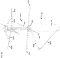
- FIGS. 18 & 19 illustrate an alternative design of antenna 200 for use with the above described antenna assembly 1.
- antenna 200 comprises driven members 202, ground plate members 203, both mounted to a central support 4.
- the design of the antenna 200 differs in that rather than being hinged directly to the central support, each of the driven members 202 are hinged to an annulus 210 which passes round the central support 204.
- the upper end of each link bar 217 is hingedly mounted to arm 218 which itself is hinged at its inner end to the upper mounting 204A.
- the opposing end of each arm 218 is connected to a driven member 202 by hinge 219.
- the drawing force on the link bar 217 is transferred through arm 218 causing driven members 202 to pivot about hinge 219 such that the annulus 210 slides downwardly along the central mounting 204 towards lower mounting 4B.
- arm 218 rotates about its hinged connection to upper mounting 204A, and hinge 219 is drawn towards the central support 204.
- the driven members 2 are caused to rotate towards a vertical orientation with the ends that were radially distant of the central support uppermost.
- each end could be provided by a separate cord, both being anchored to the spool and wrapped around it in the same direction.
- Cords 40, 50 could be comprised from other flexible elongate members, examples include, but are not limited to ropes, cables, rods or chains. Similarly the linkage 17 may take forms other than a bar.
- the knuckles 13, 14 may instead be integral part of the ground plane members. This arrangement is used in the embodiment shown in Figs 18 and 19 .
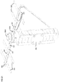
- FIGS 20-27 illustrate a further variant embodiment having a simplified deployment mechanism.
- the assembly 301 comprises an antenna assembly 301A arranged to be drawn into and out from a housing.
- the housing comprises: an inner housing 305 ( Fig 23 ) that holds the antenna 301A when stowed; a sealed casing 306 housing the circuitry for driving the antenna; the inner housing 305 and casing 306 are housed within an outer housing 307.
- a spacing 308, between the outer housing 307 and inner housing 305 carries coaxial cabling between the antenna 301A and the circuitry within casing 306.
- the space 308 also houses a pull-cord 340 in the form of a strap of webbing.
- the outer housing 307 is held within a fabric bag 350 (see Fig 21 ). Extending from either side of the bag 350 are cord guides (to allow use by left or right handed users) comprised from tongues 351 with eyelets 352 and hook/loop fastener straps 353 to secure the guide to a jacket worn by the user.
- cord guides to allow use by left or right handed users
- tongues 351 with eyelets 352 and hook/loop fastener straps 353 to secure the guide to a jacket worn by the user.
- the end cap 309 of inner housing 305 as before has an inwardly sloping wall 309A (seen best in Fig 26 ) for engagement with knuckles 313 of ground plane members 303 so as to cause rotation of the ground plane members when the antenna 301A is drawn into the housing 305.
- the end cap 309 is not provided with slots.
- a part of the lower mounting 304B of antenna 301A provided with diametrically opposed apertures 304C is housed within housing 305.
- Pins 319A 319B extend through diametrically opposed longitudinal slots 305A in inner housing 305 and through apertures 304C of lower mounting 304. It would be of course possible to use only a single pin.
- a single pull cord 340 is anchored, at a point intermediate between its ends, to pin 319A within space 308.
- a first portion 340A of cord 340 runs upwardly from pin 319A, substantially parallel with housing 5A, over a roller pulley 337 mounted to a top part of housing 305 and/or end cap 309, and then out through an aperture of outer housing 307.
- a second portion 340B of cord 340 extends away from the pin 319A in the opposite direction substantially parallel with outer wall of housing 305A, over a roller pulley 338 (see Fig 27 ) mounted to lower part of housing 305 or casing 306, and then out through a lower aperture of outer housing 7.
- the free end of the cord 340A passes over tongue 351 through eyelets 352 to guide the end of the cord 340A to a convenient position to be reached and operated by the user.
- the ends of the cord 340 may be provided with straps (as in the earlier embodiment or linked/tied together to form a loop as shown in Figure 20 .
- a pulling action on the second portion 340B causes the pin 319 to be drawn downwardly along slot 305A. This acts upon the antenna 301A drawing it downwardly into housing 305.
- the action of the knuckles 313 against the upper portion 309 of housing 305 causes the antenna 301A to collapse in a manner similar to that afore described.
- the arrangement of the antenna 301A is similar to that of Figs 18 and 19 , but with the upper end of linkage element 317 being hinged to elbow joints 320 rather than directly to arm 318 which are themselves hinged to upper mounting 304A.
- Arms 318 are rigidly mounted, at their upper end, to elbow joints 320.
- the opposing end of each arm 218 is hingedly connected 319 to lateral members 302.
- the radially inward end of lateral members 302 are connected to a ring 310 mounted over stem of support 304.
- a drawing force on the link bar 317 causes elbow joint 320 to rotated which in turn causes arm 302 to rotate about elbow joint 320.
- the lateral members 302 are caused to rotate towards a vertical orientation with the ends that were radially distant of the central support 304 uppermost.
- the driven elements of the antenna 301A are comprises from directly opposing pairs of arm 318 and corresponding lateral member 302.
- the coaxial cable extending from the circuitry in housing 306, is electrically connected to the elbow joint 320.
- the elbow joint 320 and arm 318 are comprised from good electrical conductors, such as nickel, and are in electrical contact.
- the lateral member 302 has a radially inner portion 302A and a radially outer portion 302B formed from spring metal.
- the radially outer portion 302B is in electrical contact with arm 318 through hinge 319.
- the radially inner and outer portions 302A, 302B are interposed by a central portion formed from an electrical insulator.
- the electrical insulator may be or comprised from a variety of materials, though glass plastics composite is preferred for its mechanical properties.
- first and second cord portions 340A, 340B may be provided by separate cords each anchored to the pin 319.
- the antenna 1A may comprises more or less than four laterally extending members acting as the driven element(s), and more or less than four ground members.
- the antenna When used in systems such as TACSAT it is preferred that the antenna has circular polarisation, though the invention may be used with an antenna using other polarisation.
- the driven element(s) need not collapse inwardly towards the support. Rather, the support may be substantially drawn into the housing leaving the driven element to remain outside of the housing. This could be particularly beneficial for types of antenna having a shrouded driven element, and/or are mounted to the very top of the support 304A and cannot be collapsed.
- the length of the portion 302B of the lateral member 302 radially outward of hinge 319 may vary depending on the radio frequency(s) at which the antenna is to be used. In certain embodiments the lateral member 302 may not appreciably extend radially outwards of the hinge 319.
- the antenna may not be limited to military applications or used only by soldiers. Although shown mounted on a back pack, the device could equally be mounted on the ground or a vehicle.
Landscapes
- Details Of Aerials (AREA)
- Support Of Aerials (AREA)
Description
- The present invention relates to a portable antenna and in particular but not limited to a satellite communications antenna designed to be operated whilst carried by a user.
- Typically one soldier of a unit on field patrol carries a radio which operates in conjunction with an antenna to provide satellite communication between the unit and a base.
- One type of antenna used for satellite communication is of pistol grip form. It is designed to be held in the user's hand and pointed in the direction of the satellite. Pistol grip antenna are not well suited for combat use as it is preferred that both hands of the solider are free to operate a weapon.
- Other antenna have been mounted to the soldier's rucksack to keep the soldier's hands free. When erected, the antenna's radial driven members cause the antenna to be unwieldy and liable to snag on passing objects which can lead to the antenna breaking. Rucksack mounted antenna also make the solider, and consequently the unit as a whole, more conspicuous to the enemy.
- These problems can be overcome by collapsing or dismantling the antenna when not in use, though this is time consuming and requires the soldier to remove his rucksack each time the antenna is to be collapsed or assembled.
-
US2012280869 relates to an antenna system in which the antenna is mounted to a bendable rod of sufficient rigidity to support the weight of the antenna when the rod is in a vertical orientation. - According to a first aspect of the invention there is provided a man-portable antenna assembly according to
claim 1. - The invention allows a solider to quickly erect or stow the antenna as necessary. The end of the pull-cord can for example be placed in easy reaching distance of one or both of the soldier's hands.
- In a preferred embodiment, the driven element, which when the antenna is erect, extends laterally away from the support, is foldably mounted to the support so that it can fold inwardly towards the support when the antenna is stowed. This enables the antenna to be made more wieldy and less likely to snag on passing objects when stowed.
- It is also preferred that the antenna comprises a ground plane which acts as a reflector for the driven element. It is preferred that the ground plane comprises radially extending members which are foldably mounted to the support so that they can fold inwardly towards the support when the antenna is being stowed.
- It is preferable that the mechanism comprises means to allow the antenna to be configurable by the solider with one hand. This leaves the soldier's other hand free to operate a weapon.
- It is preferred that the driven element is a dipole comprising two elongate members that extend radially away from the support in substantially opposite directions. The antenna may have two dipoles that are orientated perpendicular to one another.
- It is preferred that the mechanism comprises a further linkage between the driven element and the ground plane that is arranged to cause them to close and/or open together.
- There is favourably a further linkage between each ground plane member and the driven element. Each further linkage may work independently of the others so that if one further linkage breaks or jams the other can still operate.
- Preferably the antenna assembly comprises a housing within which the antenna is housed when stowed. It is particularly favourable that the housing acts as a mast for the antenna when in an operational state. This allows the antenna to be held in a higher position when in use to improve transmission/reception, but also provides the benefit that the antenna can be lowered when not in use making it less conspicuous and wieldier.
- In a preferred embodiment, the antenna comprises an engaging surface that engages with the housing when the mechanical linkage is operated to cause the driven member and ground plane member to fold inwards towards the support.
- It is also preferable that the mechanical linkage comprises means to retract the pull-cord after it has been pulled to operate the linkage. Favourably, the means to retract the pull-cord includes a sprung spool from which the pull-cord is wound or unwound. This reduces the chance of the cord becoming snagged. It also means that the end of the pull cord can return to the same place so that the soldier can instinctively reach for it. The use of the term 'cord' within this specification is used to include other flexible elongate members such as, but not limited to, string, rope, cable, chain, strap or webbing, which can be wound around a spool.
- It is also preferred that the mechanical linkage comprises a first pull-cord to erect the antenna and a second pull-cord to collapse the antenna. The first and second pull cords may be provided by separate portions of the same cord. Where the first and second pull-cords are separate, cords, it is favourable that the assembly comprises means to retract either pull-cord after it has been pulled. This may comprise two sprung spools associated with the first and second pull-cords, said spools arranged to rotate in opposite directions in order to release or wind the first and second pull-cords, and a biasing means connected between the two spools to provide a return tension to either spool in order to retract either the first or second pull-cords if extended.
- A further preferable feature is that the mechanical linkage includes a first engaging member fixed relative to the cord and a second engaging member fixed relative to the antenna. The first and second engaging members are arranged to engage when the pull cord is pulled in order to draw the antenna in and/or out of the housing. This allows the cord to rewind back onto the spool without affecting the configuration of the antenna. Where the mechanism comprises two pull-cords, it is preferred that each has an associated first and second engaging member in order that both can rewind.
- Alternatively, in a simpler arrangement the mechanical linkage may comprises a linking member that extends through a slot in the housing, the linking member being fixed relative to a pull-cord(s) outside of the housing, and fixed relative to the antenna inside the housing.
- The invention will now be described by example with reference to the following drawings in which:
-
Figure 1 is a perspective view of a deployed portable antenna assembly mounted to a rucksack carried by a solider; -
Figure 2 is a perspective view of the portable antenna assembly mounted to a rucksack carried by a soldier in a stowed configuration; -
Figure 3 is perspective view of the portable antenna assembly in a deployed configuration; -
Figure 4 is a perspective view of the portable antenna assembly in a stowed configuration; -
Figure 5 is a perspective view of the antenna in a deployed configuration; -
Figure 6 is a perspective view of the antenna in a stowed configuration; -
Figure 7 is a side elevation of the antenna in a deployed configuration; -
Figure 8 is perspective of the housing of the antenna assembly; -
Figure 9 is a perspective of the antenna assembly in a stowed configuration without the outer housing to illustrate the pull cord mechanism; -
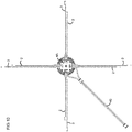
Figure 10 is a plan view of the deployed antenna assembly; -
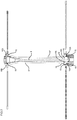
Figure 11 is a side sectional view of the deployed antenna assembly; -
Figure 12 is a side sectional view of the stowed antenna assembly; -
Figure 13 is a perspective exploded view of the spool assembly; -
Figure 14 is a side sectional view of the spool assembly; -
Figure 15 is a perspective view of the spool assembly; -
Figure 16 is a perspective close up illustrating the lower pull cord being pulled to stow the antenna; -
Figure 17 is a perspective close up illustrating the upper pull cord being pulled to erect the antenna; -
Figure 18 is a perspective view of an alternative embodiment of an antenna shown in a deployed state; -
Figure 19 is a close perspective view of the antenna ofFigure 19 ; -
Figure 20 is a perspective view of an alternative embodiment of deployed portable antenna assembly shown in a deployed configuration; -
Figure 21 is a perspective view of the antenna assembly ofFig 20 taken from the opposite side with the antenna in a stowed configuration and housed in a fabric bag; ; -
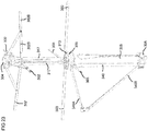
Figure 22 is a perspective view of the antenna ofFig 20 in a deployed configuration; -
Figure 23 is a perspective view of the alternative embodiment antenna assembly without outer housing; -
Figure 24 is a perspective view of the alternative embodiment antenna assembly without outer housing shown from a different vantage; -
Figure 25 is a cross section view of the alternative embodiment antenna assembly in a stowed configuration; -
Figure 26 is a cross section view of the alternative embodiment antenna assembly in erected configuration showing in close up the upper roller, and pin that is anchored to the cord and antenna; and -
Figure 27 is a cross section view of the alternative embodiment antenna assembly in erected configuration showing in close up the lower roller. - The
figures 1-17 illustrate aportable antenna assembly 1 arranged for use with a radio (not shown) to allow satellite communication, e.g. through TACSAT and/or MUOS, to a command station. - The
antenna assembly 1 is designed to be carried on a soldier's S back, preferably mounted in or on arucksack 100.Figs 1 and2 illustrate an example in which theantenna assembly 1 is mounted against the side of therucksack 100 usingstraps 101 with hook and loop fasteners. The soldier S can cause anantenna 1A to collapse into housing shown inFig 2 by pulling onhandle 57 seeFig 16 , and conversely can erect the stowedantenna 1A by pulling onhandle 39, seeFig 17 . - The
antenna assembly 1 comprises anantenna 1A having driven elements 2 (two dipoles arranged perpendicular to one another) and aground plane 3 that acts as a reflector for the dipoles. Both the drivenelements 2 andground plane 3 are mounted to a central supportingcolumn 4. - The
antenna assembly 1 further comprises a housing into which theantenna 1A can be stowed when not in use. The housing comprises an inner housing 5 (shown most clearly inFig 9 ) which holds theantenna 1A when stowed. A casing (preferably sealed) 6 mounted to theinner housing 5 holds circuitry for driving theantenna 1A. Theinner housing 5 andcasing 6 are housed within anouter housing 7. Aspacing 8, shown inFigs 11 &12 , between theouter housing 7 andinner housing 5 carries coaxial cabling between theantenna 1A and the circuitry withincasing 6. Thespace 8 also houses pull-cords - The
outer housing 7, which is removable, is secured to anupper end cap 9 of theinner housing 5, bythumb screws 11 which locate into threaded apertures 12 defined by theend cap 9. - The two driven elements (dipoles) are comprised from four
elongate members 2 that, when in an operating arrangement, extend radially away from the supportingcolumn 4. Each is spaced circumferentially from the next by around 90 degrees. - The ground plane is similarly comprised from four
elongate members 3 that extend radially away from the supportingcolumn 4 when in an operating arrangement. - When erect, the driven
elements 2 andground plane members 3 are separated by a distance of substantially a quarter of a wavelength of the intended transmission wavelength as is well known in the art. Theground plane members 3 extend radially further outwards as compared to the drivenmembers 2 so as to improve the transmission properties of theantenna 1A. - The elongate members forming the driven
elements 2 andground plane 3 are comprised from sprung steel (or other conductive material) covered with a synthetic plastics material. In some embodiments the protective casing may be omitted. - The elongate members may be releasably attached to the support. This may be achieved in a number of ways, examples including via a plug-in action similar to that used with an audio jack, or through a screw fitting. This allows any elongate member to be easily replaced should it break.
- As illustrated in
Fig 1 , the antenna assembly is orientated such that when theantenna 1A is deployed, two of theground plane members 3 extend across, and may rest upon the shoulder's of the soldier S. The drivenmembers 2 are preferably held above the soldier's S head. - As illustrated in
Figs 5-7 , eachground plane member 3 and drivenmember 2 is counter levered about a knuckle; theground plane members 3 toknuckles 13 andantenna members 2 toknuckles 14. Eachknuckle hinge 15 to either anupper mounting 4A or lower mounting 4B of the supportingcolumn 4 which allows the eachknuckle column 4 about an axis substantially perpendicular to the main axis of the supportingcolumn 4. - The
knuckle 13 of eachground plane member 3 is hingedly connected at 16 through alink bar 17 to theknuckle 14 of the drivenmember 2 supported above it. As shown inFig 7 , eachlink bar 17 is connected byhinge 16A to theground plane knuckle 13 at a point radially inward of the mountinghinge 15. Conversely, theknuckle 14 of the drivenmember 2 is connected byhinge 16B to thelink bar 17 at a point radically outward of the mountinghinge 15. Through this arrangement, rotation of a groundplane member knuckle 13 in one direction will cause the linkedknuckle 14 of the drivenmember 2 above it to rotate in an opposite direction. - A
torsion spring 18 sits over a mountinghinge 15 between eachknuckle column 4. The torsion springs 18 act to bias theknuckles column 4 into the radial configuration shown inFigs 5 and7 . As also shown in these Figures, when in this configuration, a radiallyoutward portion 13A of eachground plane knuckle 13 extends beyond the outer perimeter of thelower mounting 4B. - In order that the driven
members 2 andground plane members 3 can fold inwardly towards thecentral support 4 without obstructing each other, they are arranged to be slightly offset from a vertical alignment as seen inFig 10 . This is achieved, as shown inFigs 5 and6 , by mounting the drivenmembers 2 on one side of thehinge 16B, and theground plane members 3 to theknuckles 13 on the other side of thehinge 16B. - The
lower mounting 4B definesslots 4C through which the coaxial cables (not shown) pass in order to run up through thecentral support 4 to the drivenmembers 2. - Mounted to lower mounting 4B are four locking pins 19 (three shown in
Fig 6 ) which extend radially outward from the mounting 4B. Each lockingpin 19 defines a vertical throughhole 19A. As illustrated inFigs 9 and10 , when the antenna is assembled with theinner housing 5, each lockingpin 19 extends through alongitudinal slot 5A in thehousing 5. - As seen in
Fig 8 ,end cap 9 of theinner housing 5 has an inwardly slopinginner wall 9A. The wall defines fourslots 9B through withground plane members 3 extend when in an operational configuration. Thewall 9A optionally defines a series ofsmaller slots 9C to reduce the build up of dirt and sand. Associated with eachslot 9B is arecess 9D in the inner wall of theend cap 9B. Extending from either side into eachrecess 9D are cammingsurfaces 9E. - The
end cap 9 also comprises twoapertures 9F through which two ends of a pull-cord 40 pass out of theantenna assembly 1. - In a deployed state, the
knuckles 13 are housed in correspondingrecesses 9D of theend cap 9 withouter portions 13A resting against the camming surfaces 9E, and theground plane members 3 extending radially away from thecentral support 4 throughslots 9B. - To stow the
antenna 1A into the inner housing, a downward force is applied tocentral support 4. The reactionary force of the camming surfaces 9E against theouter portion 13A ofknuckles 13, causes theknuckles 13 to rotate up about mounting hinges 15 (against the action of spring 18) which leads to the drivenmembers 3 moving towards a vertical orientation alongside thecentral support 4. The rotation ofknuckles 13 draws thelink bar 17 in a downward direction which in turn causesknuckles 14 to rotate about mountingpivots 15 so that drivenmembers 2 are rotated downwards towards a vertical orientation as illustrated inFig 6 . - Once the
knuckles 13 of theground plane members 3 have been rotated, neither theouter portions 13A, theground plane members 3 or the drivenmembers 2 extend beyond the outer periphery of thelower mounting 4B, thus allowing theantenna 1A to pass into and be stowed within thelower housing 5 as shown inFigs 9 and12 . - The inwardly sloping
inner wall 9A acts to guide drivenmembers 2 inwardly towards thecentral support 4 in the instance that they have not folded inwardly enough to avoid contact withupper cap 9. - When it is wished to deploy the stowed
antenna 1A, an upward force exerted on theantenna 1A draws it out of thelower housing 5 throughend cap 9. Once theantenna 1A has passed sufficiently out of theinner housing 5, theground plane knuckles 13 are free to rotate under the biasing action ofsprings 18, towards a radial orientation untilouter portions 13A of theknuckles 13 abut engagement surfaces 9E. The biasing action ofsprings 18 is sufficiently strong that, once the upward force is removed, theknuckles 13 are prevented from rotating inward by the weight of theantenna 1A so that theantenna 1A remains seated on top ofend cap 9. - To provide means to stow and deploy the
antenna 1A from theinner housing 5, theantenna assembly 1 is provided with a pull cord mechanism described below. - Provided at the lower end of the
inner housing 5 is abottom cap 10 to which the sealedenclosure 6 is mounted by downwardly extending mountingspigots 20. Also extending between thebottom cap 10 andenclosure 6 are mountingspigots 21 for supportingpulleys spigot 21 incorporate mountingbrackets 22 forpulley wheels spigot 21. Also provided are guide spigots which act as cord guides 24, and acentral spigot 25 shown inFig 12 . - Seated between the
end cap 10 andPCB enclosure 6 is spool assembly 30. The spool assembly 30, as illustrated inFigs 13 - 15 comprises twoco-axial spools spiral spring 33 and aretainer 34. The assembly is arranged to allow thespools end cap 10 andPCB housing 6, and each other. - In detail,
first spool 31 is mounted over spigot 6A which extends upwardly from thePCB housing 6 in vertical alignment tocentral spigot 25.Spool 31 itself comprises aspigot 31A onto whichsecond spool 32 sits and can rotate relative to thefirst spool 31 or vice versa. Acircumferential flange 35 ofsecond spool 32 extending from a face opposing thefirst spool 31 provides ahousing 36 forspring 33. Thespring 33 is retained within the housing byretainer 34. - The
outer end 33A of thespiral spring 33 is secured toflange 35. Theinner end 33B ofspiral 33 is secured, by way ofslot 31B tospigot 31A of thefirst spool 31 which, extends throughsecond spool 32 and intohousing 36. With this arrangement, rotation of either the first or the second spool relative to the other, will cause thespring 33 to be tightened or unwound. - To maintain vertical alignment, spool assembly 30 is retained by the
central spigot 25 which engages in avertical opening 31C inspigot 31A. - Onto the
first spool 31 is wound afirst cord 40 used to deploy theantenna 1A. Thecord 40 is held onspool 31 so that both ends of thecord 40 are wound around thespool 31 in the same direction (hand). - A
first pulley 34 takes afirst end 40A of thecord 40 off thespool 31, asecond pulley 35 rotates thecord 40A by ninety degrees, thecord 40A runs upwards parallel with theinner housing 5, through abead 36, through anaperture 19A of a lockingpin 19, and up to third pulley 37 mounted to atop end cap 9 which turns thecord 40A by ninety degrees. Thecord 40A passes out ofaperture 9F in theupper cap end 9 via a guide tube 38A secured to theupper cap end 9. The guide tube 38A reduces wear and the chance of the cord snagging against theend cap 9. - A substantially identical arrangement (not shown) of pulleys on the other side of the inner casing 5 (not shown in
Fig 9 ) takes thesecond portion 40B of thecord 40 off thespool 31 and rotates thecord 40B by ninety degrees. As before, thecord 40B runs upwards, parallel with theinner housing 5, through anaperture 19A of an opposing a lockingpin 19 and up to a pulley 37B mounted to atop end cap 9 which turns thecord 40 by ninety degrees. Thecord 40 then passes out ofaperture 9F in theupper cap end 9, via a guide tube 37B where it is brought together with thefirst end 40A with atoggle 42. Both first 40A and second 40B portions ofcord 40 are attached to a fabric loopedhandle 39 to ease grabbing and pulling of thecord 40. Thecord 40 is guided throughloops 42 on one of the shoulder straps of therucksack 100 in order that thehandle 39 hangs next to the soldier's S shoulder/chest where it is in easy reach. - In an operation to erect the
antenna 1A from a stowed configuration, a pulling force on handle 39 (Fig 17 ) causes bothportions cord 40 to be unwound from thespool 31. Beads 36A, 36B which are fixed to theirrespective cord portions longitudinal slots 5A, and thecentral support 4 to which the locking pins are mounted, upwards throughend cap 9. Onceknuckles 13 have been raised into theend cap 9,spring 18 causes theground plane members 3 and drivenmembers 2 to open out as described above. Excess upward motion of theantenna 1A is checked by engagement of locking pins 19 against stoppers 41. - Once the
antenna 1A is erected and the pull handle is released,spring 33 recoils, causing thefirst spool 31 to rotate to redraw thecord 40. This can be achieved without causing theantenna 1A to withdraw intohousing 5 ascord portions aperture 19A of the locking pins. Thecord 40 is redrawn untilbead 36 engages againstlower end cap 10. - Onto the
second spool 32 is wound asecond cord 50 used to collapse and stow theantenna 1A intohousing 5. Thecord 50 is held onspool 32 with both ends of thecord 50 wound around thespool 32 in the same direction (hand).Cords respective spools - A forth
pulley 51 takes afirst end 50A ofsecond cord 50 off thespool 32, afifth pulley 52 rotates thecord 50 by about ninety degrees so that it runs upwards towards theupper end cap 9. A sixth pulley 53 mounted to theupper end cap 9 turns thecord 50A through one-hundred-and-eighty degrees.Cord 50 runs back down towards thelower end cap 10 passing thoughaperture 19A of lockingpin 19. Abead 54 is mounted tocord 50 at a point above the lockingpin 19. Thecord 50 passes throughstop 55 throughspigot 24, and passes intoguide tube 26 which runs through the PCB housing. Thecord 50 passes out through the bottom of thePCB housing 6. - A similar arrangement of pulleys (not shown) guides the
second portion 50B of thesecond cord 50 in a likewise fashion on the otherwise of theinner housing 5. The first and second portions of thesecond cord 50 are brought together bytoggle 56. Both ends of the first and second portions ofsecond cord 50 are attached to a fabric loopedhandle 57 to ease grabbing and pulling of thecord 50. - As illustrated in
Fig 1 &2 handle 57 is arranged to hang below theantenna assembly 1 in easy reach of one of the soldier's hands. - In an operation to stow the antenna from a deployed state, a pulling action on handle 57 (
Fig 16 ) causes the first andsecond portions cord 50 to be unwound fromspool 32.Beads 54 secured to the respective first and second portions (in this instance with a grub screw) are drawn downwards into engagement with lockingpins 19, whereupon further downward motion of thebeads 54 urges the locking pins 19 to move downwardly alongslots 5A. This provides the aforementioned downward force which causes theknuckles 13 to rotate and theantenna 1A to withdraw into theinner housing 5 as previously described. - Once the
antenna 1A is stowed and thepull handle 57 released,spring 33recoils causing spool 32 to rotate in the opposite direction to wind thecord 50 back onto thespool 32. During this action thepull handle 57 is drawn back towards theantenna assembly 1. Thebeads 54 mounted tocord portions 50Aupper cap 9 which stops further recoiling of thecord 50. - As mentioned above, running between the
PCB housing 6 and the drivenmembers 2 are two coaxial cables (not shown). To ensure the coaxial cables do not interfere with the operation of pull-cord mechanism, they run along the outside of theinner housing 5 throughguards 61, 62 spaced between the pairs ofcords guards 61, 62 also hold slack co-axial cable when theantenna 1A is in a stowed configuration. -
Figures 18 &19 illustrate an alternative design ofantenna 200 for use with the above describedantenna assembly 1. - As before,
antenna 200 comprises drivenmembers 202,ground plate members 203, both mounted to acentral support 4. The design of theantenna 200 differs in that rather than being hinged directly to the central support, each of the drivenmembers 202 are hinged to anannulus 210 which passes round thecentral support 204. The upper end of eachlink bar 217 is hingedly mounted toarm 218 which itself is hinged at its inner end to the upper mounting 204A. The opposing end of eacharm 218 is connected to a drivenmember 202 byhinge 219. When theerect antenna 200 is drawn intohousing 5 during a stowing operation, theground plane members 203 are caused to rotate upwardly as before and draw thelink bar 217 downwards. The drawing force on thelink bar 217 is transferred througharm 218 causing drivenmembers 202 to pivot abouthinge 219 such that theannulus 210 slides downwardly along the central mounting 204 towards lower mounting 4B. As theannulus 210 moves downwards,arm 218 rotates about its hinged connection to upper mounting 204A, and hinge 219 is drawn towards thecentral support 204. The drivenmembers 2 are caused to rotate towards a vertical orientation with the ends that were radially distant of the central support uppermost. - Variations on the above described designs are possible. For example rather than using two ends of a
single pull cord 40, each end could be provided by a separate cord, both being anchored to the spool and wrapped around it in the same direction. -
Cords linkage 17 may take forms other than a bar. - The
knuckles Figs 18 and19 . -
Figures 20-27 illustrate a further variant embodiment having a simplified deployment mechanism. Much of the assembly is very similar or identical and so the following description focuses primarily on the differences. As before, theassembly 301 comprises anantenna assembly 301A arranged to be drawn into and out from a housing. The housing comprises: an inner housing 305 (Fig 23 ) that holds theantenna 301A when stowed; a sealedcasing 306 housing the circuitry for driving the antenna; theinner housing 305 andcasing 306 are housed within anouter housing 307. Aspacing 308, between theouter housing 307 andinner housing 305 carries coaxial cabling between theantenna 301A and the circuitry withincasing 306. Thespace 308 also houses a pull-cord 340 in the form of a strap of webbing. Theouter housing 307 is held within a fabric bag 350 (seeFig 21 ). Extending from either side of thebag 350 are cord guides (to allow use by left or right handed users) comprised fromtongues 351 witheyelets 352 and hook/loop fastener straps 353 to secure the guide to a jacket worn by the user. - The
end cap 309 ofinner housing 305 as before has an inwardly sloping wall 309A (seen best inFig 26 ) for engagement withknuckles 313 ofground plane members 303 so as to cause rotation of the ground plane members when theantenna 301A is drawn into thehousing 305. Unlike the previous embodiment theend cap 309 is not provided with slots. - A part of the lower mounting 304B of
antenna 301A provided with diametricallyopposed apertures 304C is housed withinhousing 305.Pins 319AFig 26 ) extend through diametrically opposed longitudinal slots 305A ininner housing 305 and throughapertures 304C of lower mounting 304. It would be of course possible to use only a single pin. - A
single pull cord 340 is anchored, at a point intermediate between its ends, to pin 319A withinspace 308. Afirst portion 340A ofcord 340 runs upwardly frompin 319A, substantially parallel withhousing 5A, over aroller pulley 337 mounted to a top part ofhousing 305 and/orend cap 309, and then out through an aperture ofouter housing 307. Asecond portion 340B ofcord 340 extends away from thepin 319A in the opposite direction substantially parallel with outer wall of housing 305A, over a roller pulley 338 (seeFig 27 ) mounted to lower part ofhousing 305 orcasing 306, and then out through a lower aperture ofouter housing 7. The free end of thecord 340A passes overtongue 351 througheyelets 352 to guide the end of thecord 340A to a convenient position to be reached and operated by the user. The ends of thecord 340 may be provided with straps (as in the earlier embodiment or linked/tied together to form a loop as shown inFigure 20 . - In an operation to stow the
antenna 301A from a deployed state, a pulling action on thesecond portion 340B causes thepin 319 to be drawn downwardly along slot 305A. This acts upon theantenna 301A drawing it downwardly intohousing 305. The action of theknuckles 313 against theupper portion 309 ofhousing 305 causes theantenna 301A to collapse in a manner similar to that afore described. - The arrangement of the
antenna 301A is similar to that ofFigs 18 and19 , but with the upper end oflinkage element 317 being hinged to elbowjoints 320 rather than directly toarm 318 which are themselves hinged to upper mounting 304A.Arms 318 are rigidly mounted, at their upper end, to elbowjoints 320. The opposing end of eacharm 218 is hingedly connected 319 tolateral members 302. The radially inward end oflateral members 302 are connected to aring 310 mounted over stem ofsupport 304. - A drawing force on the
link bar 317 causes elbow joint 320 to rotated which in turn causesarm 302 to rotate aboutelbow joint 320. This in turn causes thelateral member 302 to pivot abouthinge 319 such that thering 310 slides downwardly over thestem 304 towards lower mounting 304B. As with the embodiment shown infigs 18 ,19 , thelateral members 302 are caused to rotate towards a vertical orientation with the ends that were radially distant of thecentral support 304 uppermost. - The driven elements of the
antenna 301A are comprises from directly opposing pairs ofarm 318 and correspondinglateral member 302. The coaxial cable extending from the circuitry inhousing 306, is electrically connected to theelbow joint 320. The elbow joint 320 andarm 318 are comprised from good electrical conductors, such as nickel, and are in electrical contact. Thelateral member 302 has a radiallyinner portion 302A and a radiallyouter portion 302B formed from spring metal. The radiallyouter portion 302B is in electrical contact witharm 318 throughhinge 319. The radially inner andouter portions - By electrically insulating the portion of the
lateral member 302 which lies substantially directly under thearm 318, i.e. radially inwards ofhinge 319, improved antenna performance has been observed. It would be possible to form the whole of radially inner portion 30A from an electrical insulator; however, use of spring metal gives the lateral member greater resilience to breakage. - In an alternative embodiment the first and
second cord portions pin 319. - Variations on the above detailed embodiments are possible. For example, the
antenna 1A may comprises more or less than four laterally extending members acting as the driven element(s), and more or less than four ground members. - When used in systems such as TACSAT it is preferred that the antenna has circular polarisation, though the invention may be used with an antenna using other polarisation.
- The driven element(s) need not collapse inwardly towards the support. Rather, the support may be substantially drawn into the housing leaving the driven element to remain outside of the housing. This could be particularly beneficial for types of antenna having a shrouded driven element, and/or are mounted to the very top of the
support 304A and cannot be collapsed. - The length of the
portion 302B of thelateral member 302 radially outward ofhinge 319 may vary depending on the radio frequency(s) at which the antenna is to be used. In certain embodiments thelateral member 302 may not appreciably extend radially outwards of thehinge 319. - It will be understood that use of the antenna may not be limited to military applications or used only by soldiers. Although shown mounted on a back pack, the device could equally be mounted on the ground or a vehicle.
Claims (11)
- A man-portable antenna assembly (1) adapted for being used whilst carried on a soldier's back, the man-portable antenna assembly comprising:an antenna (1A) with a driven element (2) mounted to a support (4), the antenna (1A) being configurable between an erect operational arrangement and a collapsed stowed arrangement;the antenna assembly comprising a mechanism which allows the antenna (1A) to be configured by the soldier between the erect operational arrangement and the collapsed stowed arrangement; characterised in that the antenna assembly (1) comprises a mechanical linkage including a pull cord (40) that extends away from the antenna assembly (1) by which the soldier can operate the mechanism to erect the antenna (1A) without taking the assembly off the soldier's back.
- A man-portable antenna assembly according to claim 1 wherein the driven element (2) comprises a number of elongate members (2) which are foldably mounted to the support (4), and which, when the antenna (1A) is erect, extend laterally away from the support (4).
- A man-portable antenna assembly (1) according to any previous claim having a ground plane (3) comprising a number of elongate members (3) which are foldably mounted to the support (4) and which, when the antenna (1A) is erect, extend laterally away from the support (4).
- A man portable antenna assembly (1) according to any previous claim comprising a housing (5) in which the antenna (1A) is drawn when in the stowed arrangement.
- A man portable antenna assembly according to claim 4 wherein the housing (5) acts as a mast for the antenna (1A) when the antenna (1A) is erect.
- A man portable antenna assembly according to claim 5 wherein the mechanism causes the antenna (1A) to move between an operation arrangement in which the antenna (1A) is supported by the housing (5) and a stowed position in which the antenna (1A) is housed within the housing (5).
- A man portable antenna assembly (1) according to any of claims 4-6 wherein the antenna (1A) is arranged when drawn into the housing (5), to engage with a surface of the housing (5) so as to cause the driven member (2) and/or ground plane member (3) to collapse.
- A man-portable antenna assembly (1) according to any claim 4-7 wherein the mechanical linkage comprises a linking member that extends through a slot in the housing (5), the linking member being fixed relative to the pull-cord outside of the housing, and fixed relative to the antenna inside the housing.
- A man portable antenna assembly according to any previous claim wherein the mechanical linkage comprises a first pull-cord (40) to erect the antenna (1A) and a second pull-cord (50) to collapse the antenna (1A).
- A man-portable antenna assembly according to any previous claim in which the antenna assembly is a satellite communication antenna assembly.
- A man-portable antenna assembly according to any previous claim wherein the antenna (1A) comprises two dipoles (2) orientated substantially perpendicular to one another; and at least four grounded radial elements (3) which act as a reflector for the dipoles; mounted about a central support (4).
Applications Claiming Priority (5)
| Application Number | Priority Date | Filing Date | Title |
|---|---|---|---|
| GBGB1223400.1A GB201223400D0 (en) | 2012-12-24 | 2012-12-24 | A portable antenna |
| GBGB1223398.7A GB201223398D0 (en) | 2012-12-24 | 2012-12-24 | Improvements to a portable antenna |
| GBGB1223396.1A GB201223396D0 (en) | 2012-12-24 | 2012-12-24 | A portable antenna |
| GBGB1223399.5A GB201223399D0 (en) | 2012-12-24 | 2012-12-24 | A portable antenna |
| PCT/EP2013/075991 WO2014102056A1 (en) | 2012-12-24 | 2013-12-09 | A portable antenna |
Publications (2)
| Publication Number | Publication Date |
|---|---|
| EP2946436A1 EP2946436A1 (en) | 2015-11-25 |
| EP2946436B1 true EP2946436B1 (en) | 2021-03-31 |
Family
ID=49955284
Family Applications (3)
| Application Number | Title | Priority Date | Filing Date |
|---|---|---|---|
| EP13823943.9A Active EP2946438B8 (en) | 2012-12-24 | 2013-12-09 | An improved portable antenna |
| EP13820742.8A Active EP2946437B1 (en) | 2012-12-24 | 2013-12-09 | A collapsible portable antenna |
| EP13820740.2A Active EP2946436B1 (en) | 2012-12-24 | 2013-12-09 | A portable antenna |
Family Applications Before (2)
| Application Number | Title | Priority Date | Filing Date |
|---|---|---|---|
| EP13823943.9A Active EP2946438B8 (en) | 2012-12-24 | 2013-12-09 | An improved portable antenna |
| EP13820742.8A Active EP2946437B1 (en) | 2012-12-24 | 2013-12-09 | A collapsible portable antenna |
Country Status (7)
| Country | Link |
|---|---|
| US (3) | US9711844B2 (en) |
| EP (3) | EP2946438B8 (en) |
| AU (3) | AU2013369549B2 (en) |
| CA (3) | CA2893651C (en) |
| DK (2) | DK2946436T3 (en) |
| GB (4) | GB201321758D0 (en) |
| WO (3) | WO2014102056A1 (en) |
Families Citing this family (13)
| Publication number | Priority date | Publication date | Assignee | Title |
|---|---|---|---|---|
| US9711859B1 (en) | 2012-02-10 | 2017-07-18 | Trivec-Avant Corporation | Soldier-mounted antenna |
| US9786984B2 (en) * | 2013-11-07 | 2017-10-10 | The United States Of America As Represented By The Secretary Of The Army | Portable antenna |
| JP6442256B2 (en) * | 2014-12-02 | 2018-12-19 | 日本放送協会 | Broadcast antenna |
| RU2602426C1 (en) * | 2015-07-20 | 2016-11-20 | Федеральное государственное унитарное предприятие "Ростовский-на-Дону научно-исследовательский институт радиосвязи" (ФГУП "РНИИРС") | Radiator for deployable antenna array |
| US10608328B2 (en) * | 2016-06-24 | 2020-03-31 | Src, Inc. | Light weight system to locate enemy artillery, mortar, and rocket fire |
| IT201800002581A1 (en) | 2018-02-12 | 2019-08-12 | Hi Te S R L | COMBINED ANTENNA FOR SATELLITE AND TERRESTRIAL RADIOCOMMUNICATIONS |
| IT201800003195U1 (en) * | 2018-08-07 | 2020-02-07 | Hi-Te Srl | PERFECTED PORTABLE SATELLITE ANTENNA |
| CN109462032B (en) * | 2018-10-10 | 2021-01-12 | 江苏三和欣创通信科技有限公司 | Multi-star dual-frequency antenna based on multi-arm spiral |
| WO2023010099A1 (en) * | 2021-07-28 | 2023-02-02 | Noodle Technology Inc. | Antenna system |
| CN115621734A (en) * | 2022-09-19 | 2023-01-17 | 西安研航电子科技有限公司 | Antenna for Microwave Power Amplifier |
| US12092679B1 (en) * | 2023-07-31 | 2024-09-17 | Phillip C. Miller | Portable system for the validation of a semi-anechoic chamber |
| CN117117465B (en) * | 2023-10-23 | 2024-01-02 | 成都智芯雷通微系统技术有限公司 | A radar antenna phased array and its use method |
| US12166276B1 (en) * | 2024-04-08 | 2024-12-10 | Custom Microwave Inc. | Deployable omnidirectional antenna for ground communication |
Citations (1)
| Publication number | Priority date | Publication date | Assignee | Title |
|---|---|---|---|---|
| US7019708B2 (en) * | 2004-04-08 | 2006-03-28 | Florenio Pinili Regala | Portable co-located LOS and SATCOM antenna |
Family Cites Families (23)
| Publication number | Priority date | Publication date | Assignee | Title |
|---|---|---|---|---|
| GB1268344A (en) | 1968-03-19 | 1972-03-29 | Plessey Co Ltd | Improvements in or relating to wide-band ground-mounted monopole antennas |
| US3579244A (en) | 1968-08-27 | 1971-05-18 | Itt | Collapsible antenna employing flexible tape radiators |
| US3568201A (en) | 1969-08-12 | 1971-03-02 | Us Navy | Air dropped antenna with deployment apparatus |
| US3665478A (en) | 1970-08-31 | 1972-05-23 | Richard C Dempsey | Foldable antenna operable in dual modes |
| NO128892B (en) | 1972-11-29 | 1974-01-21 | Standard Tel Kabelfab As | |
| US4249185A (en) | 1979-04-16 | 1981-02-03 | Cesari Robert J De | Portable, collapsible cubical quad antenna |
| US5166695A (en) | 1991-07-15 | 1992-11-24 | Motorola, Inc. | Auto-extending antenna |
| JP2872589B2 (en) | 1993-09-23 | 1999-03-17 | エイ・ティ・アンド・ティ・コーポレーション | Wireless telephone handset and antenna structure used for it |
| JP3002985U (en) * | 1994-02-18 | 1994-10-11 | 株式会社花絹コーポレーション | Mobile phone |
| JPH08279708A (en) * | 1995-04-05 | 1996-10-22 | Mitsubishi Electric Corp | Antenna device |
| JP3030360B2 (en) * | 1995-12-01 | 2000-04-10 | 日本電気株式会社 | Flat antenna for portable radio |
| JPH09205384A (en) | 1996-01-29 | 1997-08-05 | Nec Corp | Portable radio equipment |
| US5684672A (en) * | 1996-02-20 | 1997-11-04 | International Business Machines Corporation | Laptop computer with an integrated multi-mode antenna |
| US6429817B1 (en) | 2000-10-03 | 2002-08-06 | Bellsouth Intellectual Property Corporation | Retractable antenna for portable telephone |
| JP2004304541A (en) | 2003-03-31 | 2004-10-28 | Wintel Kk | Portable image communication device and wireless image transmission system |
| US7030818B2 (en) | 2004-02-02 | 2006-04-18 | Vtech Telecommunications Limited | System and method for wireless device |
| US7372423B2 (en) | 2006-10-17 | 2008-05-13 | Harris Corporation | Rapidly deployable antenna system |
| UA24286U (en) | 2007-02-09 | 2007-06-25 | State Entpr Zoria Mashproekt | Collapsible antenna assembly |
| US7969369B2 (en) | 2007-07-11 | 2011-06-28 | Harris Corporation | Body-worn antenna fastening device and method |
| FR2920595B1 (en) | 2007-09-05 | 2011-03-04 | Eversat | SOUND SATELLITE ANTENNA AND PORTABLE STATION |
| GB2456808B (en) | 2008-01-24 | 2012-05-23 | Chemring Countermeasures Ltd | Corner reflector |
| ZA201101866B (en) | 2010-03-10 | 2011-11-30 | Poynting Antennas (Pty) Ltd | Collapsible antenna |
| US8810463B2 (en) * | 2011-05-06 | 2014-08-19 | Jeffrey B. Kirkham | Antenna mount |
-
2013
- 2013-12-09 GB GBGB1321758.3A patent/GB201321758D0/en not_active Ceased
- 2013-12-09 EP EP13823943.9A patent/EP2946438B8/en active Active
- 2013-12-09 WO PCT/EP2013/075991 patent/WO2014102056A1/en not_active Ceased
- 2013-12-09 CA CA2893651A patent/CA2893651C/en active Active
- 2013-12-09 GB GB1321760.9A patent/GB2512167B/en not_active Expired - Fee Related
- 2013-12-09 GB GB1321759.1A patent/GB2512166B/en not_active Expired - Fee Related
- 2013-12-09 CA CA2893643A patent/CA2893643C/en active Active
- 2013-12-09 WO PCT/EP2013/075995 patent/WO2014102057A1/en not_active Ceased
- 2013-12-09 AU AU2013369549A patent/AU2013369549B2/en active Active
- 2013-12-09 CA CA2893647A patent/CA2893647C/en active Active
- 2013-12-09 WO PCT/EP2013/075996 patent/WO2014102058A1/en not_active Ceased
- 2013-12-09 US US14/654,989 patent/US9711844B2/en active Active
- 2013-12-09 DK DK13820740.2T patent/DK2946436T3/en active
- 2013-12-09 AU AU2013369548A patent/AU2013369548B2/en not_active Ceased
- 2013-12-09 DK DK13823943.9T patent/DK2946438T3/en active
- 2013-12-09 US US14/654,945 patent/US9634382B2/en active Active
- 2013-12-09 AU AU2013369550A patent/AU2013369550B2/en not_active Ceased
- 2013-12-09 US US14/655,032 patent/US9515374B2/en active Active
- 2013-12-09 EP EP13820742.8A patent/EP2946437B1/en active Active
- 2013-12-09 EP EP13820740.2A patent/EP2946436B1/en active Active
- 2013-12-10 GB GB1321860.7A patent/GB2512168B/en not_active Expired - Fee Related
Patent Citations (1)
| Publication number | Priority date | Publication date | Assignee | Title |
|---|---|---|---|---|
| US7019708B2 (en) * | 2004-04-08 | 2006-03-28 | Florenio Pinili Regala | Portable co-located LOS and SATCOM antenna |
Also Published As
Similar Documents
| Publication | Publication Date | Title |
|---|---|---|
| CA2893647C (en) | A portable antenna | |
| US8079176B1 (en) | Collapsible enclosure | |
| EP0560978A1 (en) | Telescoping mast with improved holddown-locking mechanism | |
| CN101170920B (en) | cantilever umbrella | |
| MX2007006511A (en) | Folding umbrella having electrically operated opening and closing mechanism. | |
| US20160113364A1 (en) | Cantilevered umbrella with rotation system | |
| WO2015188033A1 (en) | Cantilevered umbrella | |
| US7796093B1 (en) | Helicopter transportable antenna mast and stay cable system | |
| EP1206596B1 (en) | Improvements relating to clothes driers | |
| KR102145986B1 (en) | A portable and compact umbrella | |
| RU215435U1 (en) | Device for cable connection of a fixed part of the structure with a rotary, rotating within limited limits | |
| US5383624A (en) | Portable hose reel | |
| CN102429422A (en) | Umbrella cover and umbrella | |
| CN208200018U (en) | winding device |
Legal Events
| Date | Code | Title | Description |
|---|---|---|---|
| PUAI | Public reference made under article 153(3) epc to a published international application that has entered the european phase |
Free format text: ORIGINAL CODE: 0009012 |
|
| 17P | Request for examination filed |
Effective date: 20150622 |
|
| AK | Designated contracting states |
Kind code of ref document: A1 Designated state(s): AL AT BE BG CH CY CZ DE DK EE ES FI FR GB GR HR HU IE IS IT LI LT LU LV MC MK MT NL NO PL PT RO RS SE SI SK SM TR |
|
| AX | Request for extension of the european patent |
Extension state: BA ME |
|
| DAX | Request for extension of the european patent (deleted) | ||
| RAP1 | Party data changed (applicant data changed or rights of an application transferred) |
Owner name: LEONARDO MW LTD |
|
| STAA | Information on the status of an ep patent application or granted ep patent |
Free format text: STATUS: EXAMINATION IS IN PROGRESS |
|
| 17Q | First examination report despatched |
Effective date: 20190606 |
|
| GRAP | Despatch of communication of intention to grant a patent |
Free format text: ORIGINAL CODE: EPIDOSNIGR1 |
|
| STAA | Information on the status of an ep patent application or granted ep patent |
Free format text: STATUS: GRANT OF PATENT IS INTENDED |
|
| INTG | Intention to grant announced |
Effective date: 20201022 |
|
| GRAS | Grant fee paid |
Free format text: ORIGINAL CODE: EPIDOSNIGR3 |
|
| GRAA | (expected) grant |
Free format text: ORIGINAL CODE: 0009210 |
|
| STAA | Information on the status of an ep patent application or granted ep patent |
Free format text: STATUS: THE PATENT HAS BEEN GRANTED |
|
| AK | Designated contracting states |
Kind code of ref document: B1 Designated state(s): AL AT BE BG CH CY CZ DE DK EE ES FI FR GB GR HR HU IE IS IT LI LT LU LV MC MK MT NL NO PL PT RO RS SE SI SK SM TR |
|
| REG | Reference to a national code |
Ref country code: GB Ref legal event code: FG4D Ref country code: CH Ref legal event code: EP |
|
| REG | Reference to a national code |
Ref country code: AT Ref legal event code: REF Ref document number: 1377974 Country of ref document: AT Kind code of ref document: T Effective date: 20210415 |
|
| REG | Reference to a national code |
Ref country code: DE Ref legal event code: R096 Ref document number: 602013076623 Country of ref document: DE |
|
| REG | Reference to a national code |
Ref country code: IE Ref legal event code: FG4D |
|
| RAP4 | Party data changed (patent owner data changed or rights of a patent transferred) |
Owner name: LEONARDO UK LTD |
|
| REG | Reference to a national code |
Ref country code: DE Ref legal event code: R081 Ref document number: 602013076623 Country of ref document: DE Owner name: LEONARDO UK LTD, GB Free format text: FORMER OWNER: LEONARDO MW LTD, BASILDON, ESSEX, GB |
|
| REG | Reference to a national code |
Ref country code: LT Ref legal event code: MG9D |
|
| PG25 | Lapsed in a contracting state [announced via postgrant information from national office to epo] |
Ref country code: NO Free format text: LAPSE BECAUSE OF FAILURE TO SUBMIT A TRANSLATION OF THE DESCRIPTION OR TO PAY THE FEE WITHIN THE PRESCRIBED TIME-LIMIT Effective date: 20210630 Ref country code: BG Free format text: LAPSE BECAUSE OF FAILURE TO SUBMIT A TRANSLATION OF THE DESCRIPTION OR TO PAY THE FEE WITHIN THE PRESCRIBED TIME-LIMIT Effective date: 20210630 Ref country code: HR Free format text: LAPSE BECAUSE OF FAILURE TO SUBMIT A TRANSLATION OF THE DESCRIPTION OR TO PAY THE FEE WITHIN THE PRESCRIBED TIME-LIMIT Effective date: 20210331 Ref country code: FI Free format text: LAPSE BECAUSE OF FAILURE TO SUBMIT A TRANSLATION OF THE DESCRIPTION OR TO PAY THE FEE WITHIN THE PRESCRIBED TIME-LIMIT Effective date: 20210331 |
|
| PG25 | Lapsed in a contracting state [announced via postgrant information from national office to epo] |
Ref country code: SE Free format text: LAPSE BECAUSE OF FAILURE TO SUBMIT A TRANSLATION OF THE DESCRIPTION OR TO PAY THE FEE WITHIN THE PRESCRIBED TIME-LIMIT Effective date: 20210331 Ref country code: LV Free format text: LAPSE BECAUSE OF FAILURE TO SUBMIT A TRANSLATION OF THE DESCRIPTION OR TO PAY THE FEE WITHIN THE PRESCRIBED TIME-LIMIT Effective date: 20210331 Ref country code: RS Free format text: LAPSE BECAUSE OF FAILURE TO SUBMIT A TRANSLATION OF THE DESCRIPTION OR TO PAY THE FEE WITHIN THE PRESCRIBED TIME-LIMIT Effective date: 20210331 |
|
| REG | Reference to a national code |
Ref country code: NL Ref legal event code: MP Effective date: 20210331 |
|
| REG | Reference to a national code |
Ref country code: AT Ref legal event code: MK05 Ref document number: 1377974 Country of ref document: AT Kind code of ref document: T Effective date: 20210331 |
|
| PG25 | Lapsed in a contracting state [announced via postgrant information from national office to epo] |
Ref country code: AT Free format text: LAPSE BECAUSE OF FAILURE TO SUBMIT A TRANSLATION OF THE DESCRIPTION OR TO PAY THE FEE WITHIN THE PRESCRIBED TIME-LIMIT Effective date: 20210331 Ref country code: LT Free format text: LAPSE BECAUSE OF FAILURE TO SUBMIT A TRANSLATION OF THE DESCRIPTION OR TO PAY THE FEE WITHIN THE PRESCRIBED TIME-LIMIT Effective date: 20210331 Ref country code: NL Free format text: LAPSE BECAUSE OF FAILURE TO SUBMIT A TRANSLATION OF THE DESCRIPTION OR TO PAY THE FEE WITHIN THE PRESCRIBED TIME-LIMIT Effective date: 20210331 Ref country code: CZ Free format text: LAPSE BECAUSE OF FAILURE TO SUBMIT A TRANSLATION OF THE DESCRIPTION OR TO PAY THE FEE WITHIN THE PRESCRIBED TIME-LIMIT Effective date: 20210331 Ref country code: EE Free format text: LAPSE BECAUSE OF FAILURE TO SUBMIT A TRANSLATION OF THE DESCRIPTION OR TO PAY THE FEE WITHIN THE PRESCRIBED TIME-LIMIT Effective date: 20210331 Ref country code: SM Free format text: LAPSE BECAUSE OF FAILURE TO SUBMIT A TRANSLATION OF THE DESCRIPTION OR TO PAY THE FEE WITHIN THE PRESCRIBED TIME-LIMIT Effective date: 20210331 |
|
| PG25 | Lapsed in a contracting state [announced via postgrant information from national office to epo] |
Ref country code: IS Free format text: LAPSE BECAUSE OF FAILURE TO SUBMIT A TRANSLATION OF THE DESCRIPTION OR TO PAY THE FEE WITHIN THE PRESCRIBED TIME-LIMIT Effective date: 20210731 Ref country code: RO Free format text: LAPSE BECAUSE OF FAILURE TO SUBMIT A TRANSLATION OF THE DESCRIPTION OR TO PAY THE FEE WITHIN THE PRESCRIBED TIME-LIMIT Effective date: 20210331 Ref country code: SK Free format text: LAPSE BECAUSE OF FAILURE TO SUBMIT A TRANSLATION OF THE DESCRIPTION OR TO PAY THE FEE WITHIN THE PRESCRIBED TIME-LIMIT Effective date: 20210331 Ref country code: PT Free format text: LAPSE BECAUSE OF FAILURE TO SUBMIT A TRANSLATION OF THE DESCRIPTION OR TO PAY THE FEE WITHIN THE PRESCRIBED TIME-LIMIT Effective date: 20210802 Ref country code: PL Free format text: LAPSE BECAUSE OF FAILURE TO SUBMIT A TRANSLATION OF THE DESCRIPTION OR TO PAY THE FEE WITHIN THE PRESCRIBED TIME-LIMIT Effective date: 20210331 Ref country code: ES Free format text: LAPSE BECAUSE OF FAILURE TO SUBMIT A TRANSLATION OF THE DESCRIPTION OR TO PAY THE FEE WITHIN THE PRESCRIBED TIME-LIMIT Effective date: 20210331 |
|
| REG | Reference to a national code |
Ref country code: DE Ref legal event code: R097 Ref document number: 602013076623 Country of ref document: DE |
|
| PG25 | Lapsed in a contracting state [announced via postgrant information from national office to epo] |
Ref country code: AL Free format text: LAPSE BECAUSE OF FAILURE TO SUBMIT A TRANSLATION OF THE DESCRIPTION OR TO PAY THE FEE WITHIN THE PRESCRIBED TIME-LIMIT Effective date: 20210331 |
|
| PLBE | No opposition filed within time limit |
Free format text: ORIGINAL CODE: 0009261 |
|
| STAA | Information on the status of an ep patent application or granted ep patent |
Free format text: STATUS: NO OPPOSITION FILED WITHIN TIME LIMIT |
|
| 26N | No opposition filed |
Effective date: 20220104 |
|
| PG25 | Lapsed in a contracting state [announced via postgrant information from national office to epo] |
Ref country code: IS Free format text: LAPSE BECAUSE OF FAILURE TO SUBMIT A TRANSLATION OF THE DESCRIPTION OR TO PAY THE FEE WITHIN THE PRESCRIBED TIME-LIMIT Effective date: 20210731 |
|
| PG25 | Lapsed in a contracting state [announced via postgrant information from national office to epo] |
Ref country code: MC Free format text: LAPSE BECAUSE OF FAILURE TO SUBMIT A TRANSLATION OF THE DESCRIPTION OR TO PAY THE FEE WITHIN THE PRESCRIBED TIME-LIMIT Effective date: 20210331 |
|
| REG | Reference to a national code |
Ref country code: CH Ref legal event code: PL |
|
| REG | Reference to a national code |
Ref country code: BE Ref legal event code: MM Effective date: 20211231 |
|
| REG | Reference to a national code |
Ref country code: DK Ref legal event code: EGE Effective date: 20220926 |
|
| REG | Reference to a national code |
Ref country code: DK Ref legal event code: T3 Effective date: 20221004 |
|
| PG25 | Lapsed in a contracting state [announced via postgrant information from national office to epo] |
Ref country code: LU Free format text: LAPSE BECAUSE OF NON-PAYMENT OF DUE FEES Effective date: 20211209 Ref country code: IE Free format text: LAPSE BECAUSE OF NON-PAYMENT OF DUE FEES Effective date: 20211209 |
|
| PG25 | Lapsed in a contracting state [announced via postgrant information from national office to epo] |
Ref country code: BE Free format text: LAPSE BECAUSE OF NON-PAYMENT OF DUE FEES Effective date: 20211231 |
|
| PG25 | Lapsed in a contracting state [announced via postgrant information from national office to epo] |
Ref country code: LI Free format text: LAPSE BECAUSE OF NON-PAYMENT OF DUE FEES Effective date: 20211231 Ref country code: CH Free format text: LAPSE BECAUSE OF NON-PAYMENT OF DUE FEES Effective date: 20211231 |
|
| PG25 | Lapsed in a contracting state [announced via postgrant information from national office to epo] |
Ref country code: HU Free format text: LAPSE BECAUSE OF FAILURE TO SUBMIT A TRANSLATION OF THE DESCRIPTION OR TO PAY THE FEE WITHIN THE PRESCRIBED TIME-LIMIT; INVALID AB INITIO Effective date: 20131209 |
|
| PG25 | Lapsed in a contracting state [announced via postgrant information from national office to epo] |
Ref country code: CY Free format text: LAPSE BECAUSE OF FAILURE TO SUBMIT A TRANSLATION OF THE DESCRIPTION OR TO PAY THE FEE WITHIN THE PRESCRIBED TIME-LIMIT Effective date: 20210331 |
|
| PG25 | Lapsed in a contracting state [announced via postgrant information from national office to epo] |
Ref country code: GR Free format text: LAPSE BECAUSE OF FAILURE TO SUBMIT A TRANSLATION OF THE DESCRIPTION OR TO PAY THE FEE WITHIN THE PRESCRIBED TIME-LIMIT Effective date: 20210331 |
|
| PG25 | Lapsed in a contracting state [announced via postgrant information from national office to epo] |
Ref country code: MK Free format text: LAPSE BECAUSE OF FAILURE TO SUBMIT A TRANSLATION OF THE DESCRIPTION OR TO PAY THE FEE WITHIN THE PRESCRIBED TIME-LIMIT Effective date: 20210331 |
|
| PG25 | Lapsed in a contracting state [announced via postgrant information from national office to epo] |
Ref country code: MT Free format text: LAPSE BECAUSE OF FAILURE TO SUBMIT A TRANSLATION OF THE DESCRIPTION OR TO PAY THE FEE WITHIN THE PRESCRIBED TIME-LIMIT Effective date: 20210331 |
|
| PG25 | Lapsed in a contracting state [announced via postgrant information from national office to epo] |
Ref country code: TR Free format text: LAPSE BECAUSE OF FAILURE TO SUBMIT A TRANSLATION OF THE DESCRIPTION OR TO PAY THE FEE WITHIN THE PRESCRIBED TIME-LIMIT Effective date: 20210331 |
|
| PGFP | Annual fee paid to national office [announced via postgrant information from national office to epo] |
Ref country code: DE Payment date: 20251211 Year of fee payment: 13 |
|
| PGFP | Annual fee paid to national office [announced via postgrant information from national office to epo] |
Ref country code: GB Payment date: 20251219 Year of fee payment: 13 |
|
| PGFP | Annual fee paid to national office [announced via postgrant information from national office to epo] |
Ref country code: IT Payment date: 20251222 Year of fee payment: 13 Ref country code: DK Payment date: 20251224 Year of fee payment: 13 |
|
| PGFP | Annual fee paid to national office [announced via postgrant information from national office to epo] |
Ref country code: FR Payment date: 20251223 Year of fee payment: 13 |